DODGE SLEEVOIL RTL PILLOW BLOCKS - PTplace.com
DODGE SLEEVOIL RTL PILLOW BLOCKS - PTplace.com
DODGE SLEEVOIL RTL PILLOW BLOCKS - PTplace.com

You also want an ePaper? Increase the reach of your titles
YUMPU automatically turns print PDFs into web optimized ePapers that Google loves.
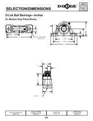
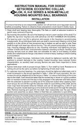
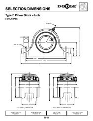
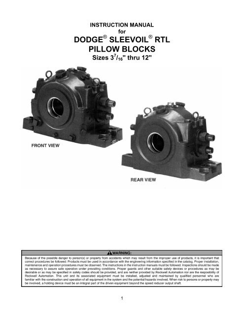
INSTRUCTION MANUALfor<strong>DODGE</strong> ® <strong>SLEEVOIL</strong> ® <strong>RTL</strong><strong>PILLOW</strong> <strong>BLOCKS</strong>Sizes 3 7 / 16 " thru 12"1
Housing caps and liner caps are matched to their basesand MUST not be interchanged. Housings and liners are tobe interchanged as assemblies only.<strong>SLEEVOIL</strong> <strong>RTL</strong> pillow blocks are designed for applicationsrequiring a bearing with high thrust load capacities and areavailable in expansion and non-expansion types.Exploded view of expansion pillow block (housing cap andliner cap not shown). Non-expansion pillow block includesthrust plate kit and split thrust collar.INSTALLATION OF BASESOptions include: thermocouple, circulating oil kit, heater andthermostat, vibration detector kit, auxiliary seal kit and endclosure.PRE-ASSEMBLY INSTRUCTIONSRefer to applicable contract/assembly drawings to verifythat all parts are available prior to assembly.Disassemble and thoroughly clean all parts of the pillowblock. The installer is the last person to inspect all parts forfit, damage and cleanliness. Care MUST be taken to avoidcontaminating the internal surfaces of the bearing.Check mounting structure to insure it is rigid, level andwell supported.Position housing base on pedestal so oil gauge is inposition specified on construction drawing. Do NOTtighten housing base to pedestal.Apply oil to the spherical seats of the housing base.2
Set liner base inhousing base.If shaft is in place, one cooling pipe from lower liner half willneed to be removed to roll liner into place.ATTENTIONCare should be taken when reinstalling coolant pipes.Use pipe sealant and tighten securely. OVER-TIGHTENING MAY RESULT IN LINER DAMAGE.Because of the closely controlled liner to housing fit, it maybe necessary to bolt the housing base down to allow the linerto slip into the housing seat. Do a preliminary alignmentcheck at this time.When using circulatingoil orthermocouple,make sure holes inliner will align withholes in housingafter pillow block isassembled. Applyoil to the linerbearing surface.NOTE: Liner has been machined to close tolerances.Scraping of bore is not necessary.INSTALLATION OF SHAFT ANDTHRUST COLLARInspect shaft to ensure it is smooth(32 mico-inch or better), free of burrsor rough spots, clean shaft in thebearing area and carefully set shaft inplace if thrust collar assembly is to beconducted inside the bearing.Standard shaft tolerance should be+.000/-.002 on all sizes unlessotherwise specified on shaft detail.If bearing is nonexpansion(fixed)type, check thrustcollar for burrs andscratches. Usecrocus cloth (NOTemery cloth orsandpaper) tosmooth any scratcheson thrustcollar faces.3If clamp-on typethrust collar is used,remove jam screwsand back off setscrews so they donot protrude into theI.D. of the thrustcollar. Removeclamp screws andmake sure joints ofcollar are clean.Place both halves ofthrust collar intoshaft groove andtighten clamp screwsalternately andevenly to torquevalue specified inTable 1.The collar faces mustbe smooth with nooffset at the split.Collar faces to betrue to shaft within.001 T.I.R.Tighten set screwsto value specifiedin Table 1. Installand tighten jamscrews1 / 10 oftorque specified forset screws.Oil shaft in thebearing area andCAREFULLY setshaft in place ifthrust collar assemblywas conductedoutsidebearing.
<strong>RTL</strong><strong>SLEEVOIL</strong>SIZESCREWSIZE(SOC. HEX)TABLE 1THRUST COLLARCLAMP SCREWSET SCREWWRENCH SCREWTORQUE SIZE(IN.-LBS.) (SOC.HEX)3 7 / 16 <strong>RTL</strong> ¼ - 20NC 1603 15 / 16 <strong>RTL</strong> ¼ - 20NC 1604 7 / 16 <strong>RTL</strong> ¼ - 20NC 1604 15 / 16 <strong>RTL</strong>5 / 16 - 18NC 3255 7 / 16 <strong>RTL</strong>3 / 8 - 16NC 5806 <strong>RTL</strong> ½ - 13NC 14257 <strong>RTL</strong> ½ - 13NC 14258 <strong>RTL</strong> ½ - 13NC 14259 <strong>RTL</strong>5 / 8 - 11NC 280010 <strong>RTL</strong> ¾ - 10NC 500012 <strong>RTL</strong> ¾ - 10NC 5000The thrust collar mustbe centered in thecavity of the liner base.WRENCHTORQUE(IN.-LBS.)5/ 16 - 24NF 1605/ 16 - 24NF 1605/ 16 - 24NF 1605/ 16 - 24NF 1603/ 8 - 16NC 2753/ 8 - 16NC 2753/ 8 - 16NC 2755/ 8 - 11NC 12005/ 8 - 11NC 12005/ 8 - 11NC 12005/ 8 - 11NC 1200Make sure oil ringsrotate freely onshaft.INSTALLATION OF THRUST PLATESFor non-expansionbearings:Clean one set ofbabbitt faced thrustplates.NOTE: Plates arematched halves andMUST NOT beinterchanged.INSTALLATION OF OIL RINGSNOTE: Do NOT use oil rings if liner cap has bafflesinstalled in the oil ring grooves.Carefully smoothany scratches onbabbitted facewith crocus cloth(NOT emery cloth orsandpaper). Oil platehalves generously.Place oil ring aroundoutside of liner baseand over shaft.First, install the platehalf without milledslots in the steelback. Press thebabbitted face againstthe thrust collarand rotate platearound shaft into linercavity.Install and peen oilring screws toinsure they aresecure. Repeat forsecond ring.Install retainer washerin groove in linerbase. Rotate plateuntil stopped byretainer washer.4
Place the otherthrust plate half (halfwith two milled slotsin steel back)against thrust collar,making sure babbittfaces thrustcollar. Clean and oilthe second thrustplate set and installin same manner. Itmay be necessaryto move the shaftslightly to obtainenough clearancein the liner cavity toinstall the lowerplate half.Total axial clearance between thrust plates and thrust collaris .015 - .030 inches.INSTALLATION OF LINER CAPApply oil to the bearing areaof liner cap.CAREFULLYlocate linercap on linerbase. These<strong>SLEEVOIL</strong>liners havematch-markspermanentlystamped atthe joint nearone end.These match marks permanently insure that parts staypaired and critical orientation of assemblies is maintained.Makes sure oil rings rotate freely. End faces of linershould have no appreciable offset.Install capscrews andtighten alternatelytotorque givenin Table 2.NOTE: If liner cap on non-expansion bearing will not drop intoplace, remove cap and reposition thrust plates tightly againstthrust collar. Reinstall liner cap.TABLE 2RT<strong>SLEEVOIL</strong>SIZE3 7 / 163 15 / 164 7 / 164 15 / 165 7 / 1667891012THREADSIZE5/ 16 - 185/ 16 - 185/ 16 - 185/ 16 - 185/ 16 - 183/ 8 - 16½ - 13½ - 13½ - 13¾ - 10¾ - 10ALIGNMENTLINER CAP BOLTSTORQUE(IN.-LBS.)13213213213213224060060060021002100Check alignment ofpillow block by notingclearance betweenhousing and shaft ateach end of thehousing—clearanceshould be uniformwithin1 / 32 ". Shimbearing pedestalwhere possible;otherwise, use fulllength shims under base as required. Alignment of pillow blockshould be accurate since the self-aligning feature of thebearing is to <strong>com</strong>pensate for normal shaft deflection.Tighten housing basemounting bolts to torquevalue given in Table 3.Shaft should rotate freely.5
INSTALLATION OF OIL SEALSWrap the O-ring(rubber cord) aroundthe shaft in the sealarea and cut it to fitthe shaft. For mosteffective sealing,ends of O-ring mustmeet. Cementingends together isre<strong>com</strong>mended.Disassemble oneseal and place onehalf on shaft withflinger facing liner.Locate O-ring in sealgroove and rotateseal half around shaftinto housing basegroove.Install other half ofseal and tightenscrews to torquegiven in Table 3.Install second seal insame manner. If endclosure is to beused, the neoprenedisc is to be installedon one end at thistime instead of thebearing seal.Consult constructiondrawing.<strong>RTL</strong><strong>SLEEVOIL</strong>SIZE3 7 / 163 15 / 164 7 / 164 15 / 165 7 / 1667891012TABLE 3HOUSING/PEDESTAL BOLTSTHREAD TORQUSIZE(IN.-LBS.)¾21007 / 8204013000130001 1 / 842001¼60001½100001¾115001¾11500215000215000INSALLATION OF HOUSING CAPWe have replaced<strong>SLEEVOIL</strong> housing gas -kets with 515 GasketEliminator. Apply gasketeliminator to <strong>SLEEVOIL</strong>housing base along outercontour of joint. NOTE:Special care should betaken at grommet area.SEAL CLAMP SCREWSTHREAD TORQUESIZE (IN.-LBS.)10–241210–241210–241210–2412¼–2033¼–20335 / 16 –18 655 / 16 –18 653 / 8 –16 1203 / 8 –16 1203 / 8 –16 1206Back off plunger screw asfar as possible andCAREFULLY locatehousing cap on housingbase. These <strong>SLEEVOIL</strong>housings have match -marks permanentlystamped on the water pipegrommet pad. These matchmarks permanently insurethat parts stay paired and critical orientation of assemblies ismaintained. Do not damage seals or housing gasket. Torquehousing bolts to value given in Table 4. A non-hardening sealer canbe used with the housing gaskets and under bolt heads to eliminatechances for leakage. The plunger screw must be loose until thehousing bolts have been tightened.TABLE 4<strong>RTL</strong><strong>SLEEVOIL</strong>SIZE3 7 / 163 15 / 164 7 / 164 15 / 165 7 / 1667891012PLUNGER SCREWWRENCH SIZE TORQUE(SOC. HEX) (IN.-LB.)3 / 88503 / 8850½12605 / 825005 / 825005 / 825005 / 82500¾3600¾3600¾4800¾4800HOUSING CAP BOLTTHREAD TORQUESIZE (IN.-LB.)¾–10 1920¾–10 19207 / 8 –9 22807 / 8 –9 22801–8 26401–8 26401 1 / 8 –7 36001 1 / 8 –7 36001¼–7 50401¼–7 50401½–6 8880Plunger screw will betightened to torquegiven in Table 4,following proceduredescribed below.CAP LOADEDBEARINGS:If shaft must be helddown to install cap,tighten plunger screwto torque given inTable 4 while shaft isheld down. Mark theposition of the plungerscrew. Loosen plungerscrew one turn andloosen shaft hold down.Next, tighten plungerscrew while tighteningshaft hold down untilplunger screw is tightened to the mark. Do NOT over tightenshaft hold down as this can misalign liner. Remove shaft holddown and tighten plunger screw locknut.NOTE: Do NOT tighten plunger screw on ac<strong>com</strong>panyingbase loaded bearing until cap loaded bearing has beeninstalled and shaft hold down removed.BASE LOADED BEARINGS: Tighten plunger screw to torquegiven in Table 4 and secure with locknut.
INSTALLATION OF GROMMETSAND OIL GAUGEInstall grommet andgrommet plate overcoolant pipes.Install grommet, grommet plate and collar over each inletpipe. Press down on collar and tighten collar set screw.Install bushings andnuts on pipes (snugnot tight). A nonhardeningsealer canbe used under thegrommet for bettersealing.Oil level gauge may be located any distance from the pillowblock by use of a coupling and pipe of desired length. Theextended pipe must be supported so that it remains straightand level with no offsets (use a spirit level—do not guess).Use pipe sealer on allconnections.When pillow block isarranged for circulatingoil, the oil level iscontrolled by the drainsystem and the oil levelgage is not needed.OPTIONSWhen pillow block is arranged for circulating oil, insert the 2small pipe nipples thru the holes in the housing cap and screwthem tightly into the liner.NOTE: ALL plumbing (oil and water) should be cleanedand flushed before being connected to the pillow block.These systems should be tested before the bearing is putinto operation.Connectcirculating oilsupply lines sothat each inletreceives an equalamount of oil. Aflow control valveand oil flowindicator arere<strong>com</strong>mended inthe inlet line. Oil flow must be adjusted to the ratere<strong>com</strong>mended by the equipment manufacturer. Connectthe drain lines. The drain piping should be vented and mustbe of adequate size to remove the oil at the specified flowrate. The housing drain must be directed straight down intoa return drain sloping away at a 15º or greater angle. Theoiling system should have a means of filtering the oil toremove any contaminating particles. A 25 micronfilter orbetter is re<strong>com</strong>mended.If using a thermocouple install it in one of the two holesspecially machined in the housing base above themounting bolts next to the waterpipe grommets. For nonexpansionbearing the thermocouple should be located inthe hole next to the thrust plate carrying the thrust load. Ifthe direction of thrust is not known, two thermocouples arere<strong>com</strong>mended. For expansion bearing the thermocouplemay be located at either end. Make sure probe extendsinto the liner. Use sealant on all threaded connections.7
Apply sealant to thepipe plug furnishedand install it in theremaining hole.Remove and reinstall,using sealer, all pipeplugs not previouslyremoved.Check constructiondrawings to determine ifcoolant (water or air) is tobe supplied to thebearings. Do not connectcoolant pipes and bearingunless constructiondrawings and/or equipmentinstructions call for this. Ifno connection isrequired, pipes can beleft open.NOTE: ALL plumbing (oil and water) should be cleaned andflushed before being connected to the pillow block Thesesystems should be tested before the bearing is put intooperation.If coolant pipes are to be connected, make sure that allpipe lengths are correct and unions are well aligned.Careless fitting will result in serious preloading of thebearing. Lengths of flexible hose between the pillow blockand rigid piping are re<strong>com</strong>mended to avoid preloading of thebearing. A regulating valve should be placed ahead of the inletand a sight drain at the outlet for liquid coolants. There<strong>com</strong>mended method of pipe connection for liquid coolants isto connect the inlet to the top pipe and the outlet to the bottompipe on the same side of the bearing. A return is then used toconnect the two pipes on the other side of the bearing. Adjustcoolant flow to rate specified on construction drawing or to suitconditions. Anti-freeze type additives may be used in coldoperating environments, otherwise purge all coolant from linerby blowing out with <strong>com</strong>pressed air or steam anytime coolant issubject to freezing. Bearing rating is generally based on amaximum water inlet temperature of 90ºF. The interior pressureof the liner should never exceed 120 psi. For deviations seeconstruction drawings or contact equipment manufacturer.CAUTIONWater pressure should never exceed 120 P.S.I.8Prior to placing the bearings into operation check forcooling pipe leaks by placing the cooling water system intooperation at normal operating pressure and flow rate. If aleak is detected, remove the coolant pipe, redope, reinstalland check again.When using air as the cooling medium, connect an inlet toeach pipe on one side of the bearing and an outlet to thepipes on the other side Adjust flow to rate specified onconstruction drawing or to suit conditions.Other Options Available:• Heater and thermoswitch• Vibration detector kit• Auxiliary seals• End cap kitLUBRICATION AND OPERATIONSince the satisfactory operation of the pillow block dependsalmost entirely on the oil film being maintained between theshaft and bearing liner surface, the use of a high quality oilfrom a reputable manufacturer cannot be overemphasizedUse a high grade straight mineral oil with rust and oxidation(R & O) inhibitors and antifoam agents. Check constructiondrawings or equipment instruction manual for proper oil. Oilviscosity is determined by the equipment manufacturer andnormally specified on the construction drawing or in theoperating manual, otherwise see Table 5 Informationregarding qualities and properties of specific oils should bereferred to the lubricant manufacturer.Table 5Re<strong>com</strong>mended Oil ViscosityIf not specified by equipment manufacturer.Room Temp.Fahr.During Start Up Speed SAE/ISO Oil RequiredBelow -10º All Consult Equipment Manufacturer-10º to 32º All SAE 10/ISO 3232º to 70º Low SAE 20/ISO 68High SAE 10/ISO 32Above 70º Low SAE 30/ISO 100High SAE 10/ISO 32 for Light LoadsSAE 20/ISO 68 for Heavy LoadsUse high grade, high quality, well refined petroleum oils for thestraight mineral type, with rust and oxidation inhibiter and anti-foamagent only.Approximate viscosity:SAE 10–183 SUS at 100ºF; 46 SUS at 210ºFSAE 20–348 SUS at 100ºF; 57 SUS at 210ºFSAE 30–489 SUS at 100ºF; 65 SUS at 210ºFISO 32–158 SUS at 100ºF; 44 SUS at 210ºFISO 68–335 SUS at 100ºF; 55 SUS at 210ºFISO 100–495 SUS at 100ºF; 66 SUS at 210ºF
After placing into operationremove inspection coversand check to make sure oilrings are bringing up oil.Operation should bechecked frequently duringthe first few days.RT<strong>SLEEVOIL</strong>SizeFluidOuncesApprox.NOTE: Check plungerscrew torque per Table 4at time of first systemshutdown.TABLE 6Oil Volume *†QuartsApprox.LitersApprox.3 7 / 16 56 1.75 1.663 15 / 16 64 2 1.894 7 / 16 80 2.5 2.374 15 / 16 128 4 3.795 7 / 16 152 4.75 4.496 224 7 6.627 336 10.5 9.948 416 13 12.309 608 19 17.9810 896 28 26.5012 1440 45 42.59* Volume of oil req’d to fill pillow block to top of CENTER CIRCLE of oil gauge.† 32 fluid ounces = 1 quart = 94636 LitersIf noise develops, check alignment of housing, plungerscrew and all operating parts. Check all points and tightenscrews and nuts after several days operation. Maintain oillevel above bottom of center circle at all times whileunit is in operation.Oil Maintenance ScheduleDrain, flush, and refill with oil after 2 to 3 weeks of initialbreak-in operation. Since the satisfactory operation of thebearing depends entirely on an oil film being maintainedbetween the shaft and the bearing liner surface, it isre<strong>com</strong>mended that an oil analysis be performed at theseregular intervals.• Every 3 months for 24 hour/day service• Every 6 months for 8 hour/day serviceAcceptably of oil should be referred to the lubricantmanufacturer. If oil quality is acceptable then repeat this9procedure in 3 month intervals. Visually check oil forcontamination between oil analysis checks. Oil service lifedepends upon several factors such as ambient conditions,operating temperature and frequency of bearing starts andstops. It is re<strong>com</strong>ended that the oil be changed at leastonce per year for unfiltered static applications. Removingcontaminants through the use of either the OLF (Oil Leveland Filtration) Unit or a circulating oil system can extend oilservice life. Consult equipment manufacturer for moreinformation.Any questions about installation, maintenance andarrangement of coolant or oil connections should bereferred to the equipment manufacturer.NOTE: Auxillary seals are re<strong>com</strong>mended for outdoorapplications, contaminated atmospheres, and high volumeof air flowing over the bearing.NOTE: Bearings should NOT be stored outdoors beforeinstallation. For extended or outdoor storage, contactequipment manufacturer for special precautions againstcorrosion.NOTE: Bearings (and shafts) allowed to set idle forextended periods after being run MUST be protectedagainst corrosion. If the unit can not be run for severalminutes at least once a week, consult equipmentmanufacturer for special lubrication instructions.TemperatureThe bearing temperature will increase after start-up until itsnormal operating level is reached. Some fluctation due toambient temperature change is normal but a drasticchange MUST be investigated. Normal runningtemperature should not exceed 180ºF. (Check withequipment manufacturer to see if another operatingtemperature has been specified.)Low ambient and operating temperatures can be asharmful to the bearing as high temperatures. A heater andthermoswitch would be required for such applications.Minimum Temperature at Start Up:SAE 10/ISO 32 oil, 45ºFSAE 20/ISO 68 oil, 70ºFSAE 30/ISO 100 oil, 85ºFHeaters are intended to heat the oil in the sump prior tostart-up and should be shut off when the fan stops running.ATTENTIONIf heaters are used, be sure heaters are off when oilis removed from bearing.VibrationAny significant vibration or imbalance MUST be corrected.Check with equipment manufacturer for acceptableconditions.
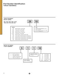
<strong>SLEEVOIL</strong> <strong>RTL</strong> <strong>PILLOW</strong> <strong>BLOCKS</strong>ItemDescriptionNo.Replacement Part NumberReq’d 3–7/16 3–15/16 4–7/16 4–15/16 5–7/16 6* 7* 8* 9* 10* 12*<strong>RTL</strong> Non-Exp. Pillow Block (A) 132362 132363 132364 132365 132366 132367 132368 132369 132370 132371 132372<strong>RTL</strong> Exp. Pillow Block (B) 132474 132475 132476 132477 132383 132384 132385 132386 132387 132388 132389<strong>RTL</strong> Modular Housing 132373 132374 132397 132398 132399 132411 132412 132413 132414 132437 132438<strong>RTL</strong> Housing Mach* 1 132379 132380 132381 132382 132390 132391 132392 132393 132394 132395 13239612 Drain Plug 1 430012 430012 430012 430012 430012 430012 430012 430012 430014 430014 43001414 ∆ Housing Bolt 4 411189 411190 411196 411197 411205 411205 411224 411227 411228 411229 411230Gasket Eliminator-515 1 427359 427359 427359 .... .... .... .... .... .... .... ....16 Gasket Eliminator-515 2 .... .... .... 427359 427359 427359 427359 427359 427359 427359 42735918 Oil Gage 1 430135 430135 430135 430135 430135 430135 430135 430135 430135 430135 43013519 Oil Level Plug 1 430014 430014 430014 430014 430014 430014 430014 430014 430014 430014 43001420 Inspection Cover 2 432198 432198 432198 432198 432198 432198 432198 432198 432198 432198 43219822 Plunger Screw Assembly 1 390522 390522 390525 391095 390571 390571 390572 391089 391092 391607 39160724 Plunger Screw Nul 1 133368 133368 133369 133369 133369 133369 133369 133370 133370 133371 133371* <strong>RTL</strong> Grommet Kit 1 132645 132646 132646 132647 132647 132647 132647 132648 132648 132649 13265026 ∆ <strong>RTL</strong> Grommet 2 133023 133035 133035 133037 133037 133037 133037 133012 133012 133039 13301028 ∆ <strong>RTL</strong> Grommet Plate 2 133028 133045 133045 133047 133047 133047 133047 133029 133029 133143 13301130 ∆ <strong>RTL</strong> Bushing (Locktube) 4 133167 133170 133170 133172 133172 133172 133172 132210 132210 133168 13317932 ∆ <strong>RTL</strong> Locknut 8 464923 460964 460964 460965 460965 460965 460965 463617 463617 464927 46492634 Oil Ring 2 130056 130057 130058 130059 130060 130078 130065 130066 130068 130073 13007136 Clamp Seal Assy 2 132181 132182 132183 132184 132185 132186 132187 132188 132189 132190 13219138 O-Ring 2 418016 418020 418024 418028 418032 418038 418045 418052 418057 418059 41806142 Rtl Liner Assy* 1 132420 132421 132422 132423 132424 132425 132426 132427 132428 132429 13243044 ∆ <strong>RTL</strong> Coolant Pipe 4 430194 430171 430171 430176 430176 430176 430176 430191 430191 430182 430192 ∆ Dowel Pin 2 420053 420053 420053 420053 420053 420053 420088 420088 420088 4201188 420118 ∆ Cap Screw 417095 417095 417093 417095 417093 417117 417184 417184 417184 417260 417260Non-Expansion Accessories Thrust Plate Kit 1 132218 132219 132220 132221 132222 132223 132224 132225 132226 132227 132228 Split Thrust Collar 1 132151 132152 132153 132154 132155 132156 132157 132158 132159 132160 132161Optional Accessories Auxillary Seal Kit 2 132811 432181 432184 432187 133932 133933 133937 133938 132814 132816 132819 Housing End Cap Kit 1 132542 432190 432193 432196 132546 132547 132548 132549 132564 132565 13256645 Circulating Oil Intet[??162] Plug 2 430014 430014 430014 430014 430014 430016 430016 430016 430016 430016 43001646 Circulating Oil Drain Plug 1 430018 430018 430018 430019 430019 430019 430019 430019 430019 430022 430022 Circulating Oil Grommet Kit 1 132203 132203 132203 132203 132203 132205 132205 132205 132205 132205 132205 Vibration Det. Adpt Kit 1 430153 430153 430153 430153 430153 430153 430153 430153 430153 430153 43015348 Thermostat Plug 1 430012 430012 430012 430012 430012 430012 430012 430012 430012 430012 430012 Thermostat 1 133116 133116 133116 133116 133116 133116 133116 133116 133116 133116 13311650 Heater Plug 1 430014 430016 430016 430017 430017 430017 430017 430017 430017 430017 430017 Heater 1 132836 132838 132838 132839 132839 132839 132840 132840 132840 132840 132840* These parts are assemblies and include the parts listed below them marked “∆”.∆ These parts make up the assembles under which they are listed. Not shown on drawing.† 2 required for sizes 3–7/16" thru 6", 4 required for sizes 7" thru 12". Clamp seal assembly does not include O-Ring. Order O-Ring by individual part number.(A) Non-Expansion Pil Bik includes modular hsg, liner assy. thrust plate kit, and split thrust collar.(B) Expansion Pil Bik includes modular hsg and liner assy.These <strong>SLEEVOIL</strong> housings and liners have nameplatesattached beginning June of 1988 identified by a six-digitpart number which fully identifies the housing and/or liner.Liner nameplates are pinned to the <strong>SLEEVOIL</strong> liner capnear an oil ring inspection hole. Housing nameplates arepinned to the housing foot parallel to the shaft. Refer tothese part numbers when ordering replacement parts.10
www.baldor.<strong>com</strong> www.ptplace.<strong>com</strong> www.dodge-pt.<strong>com</strong> www.reliance.<strong>com</strong>Baldor Electric Company HeadquartersP.O. Box 2400, Fort Smith, AR 72902-2400 U.S.A., Ph: (1) 479.648.5792, Fax (1) 479.648.5792, International Fax (1) 479.648.5895<strong>DODGE</strong>/Reliance Division6040 Ponders Court, Greenville, SC 29615-4617 U.S.A., Ph: (1) 864.297.4800, FAX: (1) 864.281.2433IM499970 04/07 Copyright © 2007 Baldor Electric Company All Rights Reserved. Printed in USA.This material is not intended to provide operational instructions. Appropriate instructionmanuals and precautions should be studied prior to installation, operation or maintenance ofequipment.11