
Create successful ePaper yourself
Turn your PDF publications into a flip-book with our unique Google optimized e-Paper software.
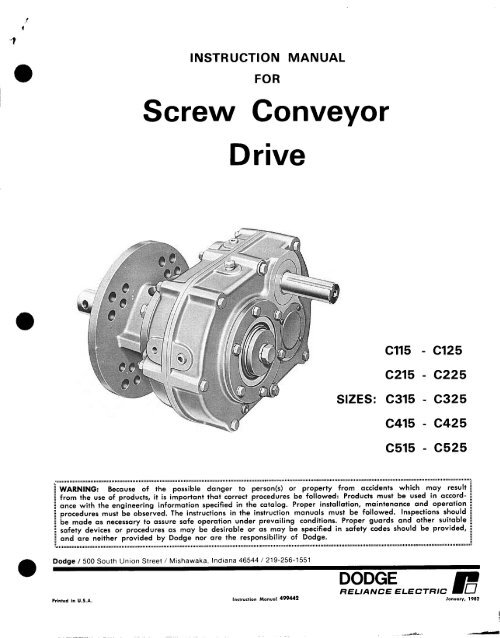
INSTRUCTIONMANUAL<strong>Screw</strong>FOR<strong>Conveyor</strong><strong>Drive</strong>Cl15C215- Cl25- C225SIZES: C315 - C325C415C515- C425- C525WARNING: Because of the possible danger to person(s) or property from accidents which may resultfrom the use of products, it is important that correct procedures be followed: Products must be used in accordancewith the engineering information specified in the catalog. Proper installation, maintenance and operationprocedures must be observed. The instructions in the instruction manuals must be followed. Inspections shouldbe made as necessary to assure safe operation under prevailing conditions. Proper guards and other suitablesafety devices or procedures as may be desirable or as may be specified in safety codes should be provided,and are neither provided by Dodge nor are the responsibility of Dodge.,,,,,,,,,,,,,,,,,,,,,,,,,,,,,,,,,, II ,,,,,,,,,,,,,,,, 11111111,,,,,,,,,,,,, 1,111111111,,,,,,,,, 111111111111111111 111,11111111111111~1111111(1111111111111,,~~~,,,,,,,,,,,,,,,,,,,,,,,,,,,,,,,,,,,,,,,,,,,,,,,,,,,,,,,,,,,,,,,,,,,,~~~,,,,,,,,,,Dodge / 500 South Union Street / Mishawaka, Indiana 46544 / 219-256-1551DODGERELIANCE ELECTRIC r 0Printed in U.S.A. Instruction Mcmual 499442 Jmuary, 1982
RETAINERBOLTDRIVESHAFT7SEAL RETAININGRINGRETAINERSCREW CONVEYORSPEED REDUCERDRiVE-Fig. 1 -AssemblyNOTE:A <strong>Screw</strong> <strong>Conveyor</strong> <strong>Drive</strong> consists of three sub-assembliesKsted below.1. Reducer - Includes speed reducer, shaft retainer,retainer bolt and lockwasher.2. Adapter Assembly - Includes adapter bolts, lockwashers,a lip type seal, 2 braided type seals and sealretaining ring.3. <strong>Drive</strong> Shaft - Includes shaft and key.Make certain none of the parts have been damagedin shipment. Any shipping damage should be promptlyreported to the carrier. Read all instructions in this manualbefore attempting to assemble or install the <strong>Screw</strong> Con-veyor <strong>Drive</strong>. It is important that assembly be performedin the following sequence and that each step be <strong>com</strong>-pleted before continuing to the next.‘, ASSEMBLY1. Place reducer on blocks that it lays flat with the inputshaft down. ‘>2. Position’adapter on reducer output hub so that smallend (end with 12 holes) rests on reducer. Select the 4mounting holes to match the shaft used (See Fig. 1). Note:“A” adapters used on Cl and C2 reducers with 1%” driveshafts have only 4 holes on the small end.3. PItice adapter‘ screws and lockwashers thru adapterand thread into reducer. Do Not Tighten.4. Select either lip type or braided type seals andinstall as follows:lip Type Seals. Place seal in adapter so that springfaces out. Seal should be tapped evenly into place in theadapter with a soft hammer, applying force only on theouter corner of the seal. Fill, ,cavity between lips of sealwith grease. Install seal retainer ring by tapping with ahammer. Apply grease to adapter .section of shaft (middlesection]. Slide shaft, keyseated end first, into adapter andthru reducer. Note: Be extremely careful when slidingadapter sec?ion of shaft Jhru seal to prevent seal lipsfrom being damaged or rolled over.Braided type seals. Flatten both seals with a soft hammer.Place seals in adapter, one on top of the other withjoints offset from each other. Lay retaining ring looselyon top of seals. Slide. shaft, keyseated end first, intosdqpter and thru reducer. Take care to clear the sealswith the adapter section “‘of the shaft. Once shaft hasbottomed, seat r@tdiner ring by simultaneously hitting theFdce of the ring on opposite sides of the shaft with twohammers.\\For I $ ,2” e 35 Drii shafts\ For 3” <strong>Drive</strong> Shaft5. Carefully place reducer on its side. Rotate shaft toalign keyseats in shaft and output hub and install key.Install shaft retainer, lockwasher and bolt. Tighten boltto torque specified in table 3 on page 5.6. Lay reducer on blocks with input shaft down andtighten adapter bolts to torque specified in table 3 onpage 5.7. If waste packing is to be used it may be installedthru access hole provided in the adapter. Waste packing,not furnished with the <strong>Screw</strong> <strong>Conveyor</strong> <strong>Drive</strong>, may be usedas a separate seal option or in <strong>com</strong>bination with eitherthe lip or braided seals. .INSTALLATION1. Determine the running position of the <strong>Screw</strong> <strong>Conveyor</strong><strong>Drive</strong>. Running positions are shown in fig. 2. Note thatthe reducer is supplied with 7 plugs; 5 around the sides ofthe reducer for horizontal installbtions and 1 on eachface for vertical installations. These plugs must be arrangedrelative to the running position as follows:Horizontal Installations - Install the magnetic drain plugin the hole closest to the bottom of the reducer. Throwaway the tape that covers the filler/ventilation plug inshipment and install plug in topmost hole. Of the 3remaining plugs on the sides of the reducer, the lowestone is the minimum oil level plug.Vertical Installations - Install the filler/ventilation plugin the hole provided in the top face of the reducer housing.Use the hole in the bottom face for the magneticdrain plug. Of the 5 remaining holes on the sides of thereducer, use a plug in the upper housing half for theminimum oil level plug.p(q]L P(JL @y-yL PfgLPosition “A” Position “B” Position “C” Position “D”HDRIZDNTALPi&PAPRICATIONSp’a;;”Position “E” Posi lion 3VERTICAL APFLICATIOh3L6 : Brcathcr; D: Drain; L: 011 Level Plug; P: PlugFig. 2 - Mounting Positions442-2DL__ -.
Note: If motor mount, -motor and sheaves are to beinstalled on reducer before mounting <strong>Screw</strong> <strong>Conveyor</strong><strong>Drive</strong> to trough end, bypass step 2; perform steps 3 and4. and then return to step 2.2. On sizes C3, C4,’ and C5 remove the plastic plugthat protects the threaded hole in the reducer and installeyebolt supplied with reducer. Hoist the <strong>Screw</strong> <strong>Conveyor</strong><strong>Drive</strong> into position. Slide shaft into screw and adapter overtrough end studs. Only one set of adapter holes will fitover trough end studs. If the mounted position of the<strong>Screw</strong> <strong>Conveyor</strong> <strong>Drive</strong> varies by 15” from any of the fourhorizontal mounting positions shown in fig. 2, an incorrectset of holes has been selected for coupling adapter toreducer. This can be corrected by removing adapterscrews and rotating reducer to its proper position. Reinstalland tighten adapter screws to torque specified intable 3 on page 5. Install lockwashers and tighten nuts ontrough end studs. Attach drive shaft to screw.6. Retighten bolts and pipe plugs after a few daysoperation. This prevents oil leakage.3. Remove the three bolts from reducer housing requiredfor mounting the SCD Motor Mount. Place the motor mountin position and install the three housing bolts suppliedwith the motor mount. Tighten bolts to torque specifiedin table 3 on page 5.4. Install motor, drive sheave and driven sheave so thatdriven sheave is as close to the reducer housing as practical.Install V-belt and tension with the four adjustingscrews provided on the SCD Motor Mount. Make requiredelectrical connections for motor.5. Because reducer is shipped without oil, it is necessaryto add the proper amount before operating the drive.Use a high grade petroleum base, rust and oxidation inhibited(R & 0) gear oil - see lubrication tables.Fig. 3 - Complete <strong>Drive</strong>Note: Belt guard removed for photographic purpose.LUBRICATIONUnder average industrial operating conditions, the Iubricantshould be changed every 2500 hours. of operationor every 6 months, whichever occurs first. Drain reducerand flush with kerosene, clean magnetic drain plug andrefill to proper level with new lubricant. Caution: Toomuch oil will cause overheating and too little will resultin gear failure. Check oil level regularly.Under extreme operating conditions, such as rapid riseand fall of temperatures, dust, dirt, chemical particles,chemical fumes or oil sump temperatures above 200” F,the oil should be changed every 1 to 3 months dependingon severity of conditions.Table 1 - Oil VolumesNOTE:Pour point of lubricant selected should be at least10” F lower than expected minimum ambient startingtemperature.Extreme pressure (EP) lubricants are not re<strong>com</strong>mendedfor average operating conditions.Special lubricants may be required for food and drugindustry applications where incidental contact with theproduct being manufactured may occur. Consult a Iubricationmanufacturers’ representative for his re<strong>com</strong>mendations.Volume of Oil Required to Fill Reducer to Oil level PlugREDUCERSIZEt Position A t Position 6 t Position C t Position D IIt Position-E t Position FFluidi/f:, Quarts* Liters G/f:, QuartsA Liters i/Ei,“,, CJ;p”p;$ litersIAPPM IAPP~M (App,ox, (.Approxl WPPWIAPPW rp;;o;;WPPWWPPMtCl15Cl25 16 % .40 16 % .48 20 N .59 24 %1 .95 40 1% 1.18C215C225 28 % 33 32 1 .95 20 % .59 32 11% 1.54 56 1% 1.66C315C325 40 1% 1.42 40 1% 1.42 24 % .71 44 1%C415C425 60 1% 1.77 72 2% 2.13 40 1% 1.18 56 1%C515C525 104 3% 3.08 128 4 3.79 104 3% 3.08 128 4t Refer to Fig. 2 on poge 2 for mounting positions.A U. S. Measure: 1 quart = 32 fluid ounces = .94646 liters.1.30 84 2% 2.48 96 3 2.84I-I1.66 108 3% 3.19 136 4% 4.023.79 224 7 6.62 272 0% 8.04NOW If reducer Position is to vary from those shown in Figure 1 eithermore or less oil may be required. Consult factory.442-31., 4
Table 2 - Oil Re<strong>com</strong>mendations for Average Operating ConditionsRatio andRoom Temp.Output RPM o Fohr. S. A. E.NO.rpm251 15:l - up to 45 75 rpm25:l - 46 rpm and Up15:l - 76 rpm and UptOILAGMALb. No.VISCOSITYASTMMetric Equiv.SUS @iI 100’ F. c St @iI 37.0” c.- 25’ thr; 60” 1 ow40 - - -0” thru 100” 40 4 626 to 765 135 to 165101” thru 180’ .50 5 918 to 1122 198 to 242- 25” thru 60”0” thru I&101” tbru 180”lOW30 - -30 3 417 to 510 90 to 11040 4 626 to 765 135 to 165REPLACEMENT O$ PARTSDodge is prepared to repair <strong>Screw</strong> <strong>Conveyor</strong> <strong>Drive</strong>speed reducers for customers who do not have the-properfacilities or for those who desire factory service. However,if the customer has access to an arbor press,equipment for heating and shrinking bearings and gearson shafts, and the tools normally found in a maintenancedepartment, the <strong>Screw</strong> <strong>Conveyor</strong> <strong>Drive</strong> speed reducer caneasily be disassembled and reassembled by careful attentionto the following instructions.Cleanliness is very important to prevent the introductionof dirt into the bearings and other parts of thereducer. The oil seals are of the rubbing type and considerablecare should be exercised during disassembly orreassembly to avoid damage to the surfaces on whichthese seals rub. Any sharp edges on the input shaft oroutput hub should be covered with adhesive tape orpaper before performing any work on the unit. Nicks andburrs on surfaces of the input shaft or output hub shouldbe removed.ORDERING PARTSWhen ordering parts specify <strong>Screw</strong> <strong>Conveyor</strong> <strong>Drive</strong> Sizeand Serial No., part name, part number and quantity.Parts that must be pressed from shafts or output hubshould be removed before ordering parts. This assuresthat those parts, if damaged during pressing operation,will be replaced. Do not press against the outer race ofany ball bearing.It is re<strong>com</strong>mended that when a pinion or gear is replaced,its mating gear or pinion be replaced also. Thisinsures that the gear teeth will mesh properly. If the largegear on the output hub must be replaced, it is suggestedthat an output hub assembly, consisting of a gear assembledon an output hub, be ordered to secure an outputhub with undamaged surfaces on which the oil seals rub.However, if the old output hub is to be used, carefullypress the gear and bearing cones off. Thoroughly examinethe area under the oil seals for scratches or any otherdamage resulting from the pressing operation. To preventleakage at the oil seals, the rubbing area must be smooth.Replacements for the oil seals should be ordered, dueto the probability of these parts being damaged duringdisassembly.442-40If replacing an output hub bearing, output hub orreducer housing, it is advisable to order a set of outputhub shims because the adjustment of the output hubbearing will be affected.REMOVING SCREW CONVEYOR DRIVE PROM THE TROUGHENDDisconnect any electrical power to the drive. Drainlubricant .from reducer. Uncouple drive shaft and’screw.Remove nuts from trough end studs. Support drive bymeans of hoist and carefully pull unit away from troughend to slide drive shaft out of screw.DISASSEMBLY1. Remove motor from motor mount. Remove retainer”bolt, lockwasher and shaft retainer from drive shaft.Pull drive shaft out of reducer from adapter side. Removeadapter.2. Position reducer on its side and remove all bolts.Gently tap the output hub and input shaft with a softhammer (rawhide not lead hammer) to separate thehousing halves. Open housing evenly to prevent damageto the parts inside.3. Lift shaft, gear and bearing assemblies from housing.4. Remove input shaft, output hub and adapter seals.Remove output hub seal carrier and shims. Remove outputhub bearing cups from housing.5. Clean all parts in solvent, inspect for damage andcoat with oil.REASSEMBLY1. Output Hub Assembly: Heat gear to 325 to 350’ F.to shrink onto output hub. Heat bearing cones to 270 to290” F. to shrink onto hub.2. Countershaft Assembly: Shaft and pinion are inte-gral. Press gear and bearings onto shaft. Press againstinner (not outer) race of bearings.3. Input Shaft Assembly: Shaft and pinion are integral.Press bearings on shaft. Press against inner (not outer)raceof bearings.4. <strong>Drive</strong> the two dowel pins back into position in theright-hand housing half (adapter mounting side). Placehousing half on blocks to allow clearance. Put the outputhub bearing cup in place, make certain that it is properlyseated in the housing..
5. Mesh output hub and countershaft together and placein housing half. Place input shaft assembly in housinghalf. Tap lightly with a soft hammer (rawhide not leadhammer) until bearings are properly seated in housing.Make sure that the snap rings on the O.D. of the bearings<strong>com</strong>e into contact with the housing.6. Clean housing flange surfaces on both halves, makingsure not to nick or scratch flange face. Place a new beadof gasket eliminator on flange face and spread evenlyover the entire flange leaving no bare spots. Note: Ifreducer was originally supplied with a housing gasketdo not use gasket eliminator. Reorder gasket per partnumber given in parts list.7. Place output hub bearing cup in other housing half.Make sure cup is properly seated in housing. Place housinghalf in position over dowel pins and tap with a softhammer (rawhide not lead hammer) until housing halvesare together. Install housing bolts and tighten evenly. Thefinal wrench torque for housing bolts is listed in table 3.8. Install the output hub seal carrier and the shimsremoved at disassembly. Tighten carrier cap screws whilerotating the output hub to make sure the bearings do notbind. If the bearings start to bind, add more shims.Torque, the carrier bolts to the value shown in table 3.Attach an indicator to the housing and set the gage onTable 3 - Bolt Tightening Torque Valuesthe top end of the output hub. Insert a pry bar underother end of the hub and force it upward. The axialplay of the output hub will be given by the indicatorreading. Add or remove shim stock to attain a readingof from .OOl” to .003”. Remove seal carrier and placea x” diameter bead of Dow Corning RTV732 sealant’onthe face around the I.D. of the last shim (sealant is tobetween shim and reducer housing). Reinstall outputseal carrier and tighten carrier screws to torque shownin table 3.9. Install oil seals. Extreme care must be observed wheninstalling seals on input shaft and output hub to avoidcontact with any sharp edges. This danger of damageand consequent oil leakage can be decreased by coveringall sharp edges with adhesive tape or paper before install-ing seals. Chamfer or de-burr housing bore if end of boreis sharp or rough. Fill cavity between lips of seal withgrease. Seals should be pressed or tapped evenlyplace with a soft hammer (rawhide not lead hammer)applying force only on the outer edge of the seals.slight oil leakage may be evident at the seals duringinitial running in, but will disappear unless seals havebeendamaged.10. Reassemble and install the <strong>Screw</strong> <strong>Conveyor</strong> <strong>Drive</strong>in accordance with the instructions in the front ofmanual.Table 5 - Manufacturers Part Numbersfor Replacement Countershaft BearingsCl15Cl25I360I360I1800I200C215C225360I600I1800I360C215C225391757 6304NR 391757 6304NRc315C325390288 305NR 390288 305NRc415C425391759 5306NR 390295 306NRc515C525390302 308NR 390302 308NRTable 4 - Manufacturers Part Numbersfor Replacement Output Hub BearingsSCREW 1 Output Hub BearingCONVEYORDRIVEDODGE Part NumberTimken Part NumberSIZETable 6 - Manufacturers Part Numbersfor Replacement Input Shaft BearingsInput Shaft BearingInput Shaft BearingSCREWInput Side Adapter SideCONVEYOR 1I.Cl15Cl25C215C225390812 390816 JLM710949 JLM710910c315C325391988 391989 JLM714149 JLM714110c415C425c515C525-c------G390836 39084 1 JM716649 JM716610II391990 391991 JM720249 JM720210c415C425c515C525390293 6208NR 390288 305NR! I 1 I390298 210NR 390299 6307NR
PARTS fOR Cl15 thru C525 SCREW CONVEYOR DRIVE SPEED REDUCERSNOTE: The two digit numbers are for reference only. Order partsby the six digit numbers in the Parts list.Each six digit number is a <strong>com</strong>plete identification of the part or assembly.24‘\64 4-- 30\72‘70
LF’.’‘0PRefer.*nce1012161820b&2224PARTS FORCl15 thru C525 SCREW CONVEYOR DRIVE SPEED REDUCERSNcme of PartHOUSING ASSEMBLY +A R.H. Housing Half* L.H. Housing HalfA Air VentA Housing BoltA LockwasherA WasherNO.leq’cCl15 and Cl25 C215 and C225 C315 and C325 C415 and C425 C515 and C525Part No. Part No. Port No. Part No. Part No.391021. . . . . .. . . . . .241237411418419011419092391022352085352086241237411418419011. . . . . .391023354185354186241237411440419012. . . . . .391024 391025354185 . . . . . .354186 . . . . . .241237 245237411442 411464419012 419013. . . . . . 419096.Hex Nut407087 407087 407089 407089 407091A Dowel Pin420089 420089 420103 420103 420110* Pipe Plug430031 430031 430031 43003 1 430033A Magnetic Drain PlugA Countershaft Bearing Cover -Input Side43006026222 1430060?42224430060243224430060354114430062355060A Countershaft Bearing Cover Gaskei(Input Side). . . . . . . . . . . . 354113A Countershaft gearing Cover <strong>Screw</strong>(Input Side) ,.... . . . . . . . . . . . . 415022A Countershaft Searing Cover -Adopter Side* Input Shaft Bearing Cover241224241224b* Housing Gasket l 1 241219i32”*34*36’38*Retainer BoltLockwasherShaft Retainerinput Shaft j 15:l Ratioand Pinion ( 25:l RatioInput Shaft KeyInput Shaft SealInput Shaft Bearing - Input SideAInput Shaft Bearing - Adopter Side!COUNTERSHAFT 15:l RatioASSEMBLY * 25:l RatioA Countershaft and PinionA First Reduction j 15:1 RatioGear \ 25:l Ratio46* ‘Gear Key48*50*54*56”50*60*Countershaft Bearing - Input SideACountershaft Bearing - Adapter Side,OUTPUT HUB ASSEMBLY +A Output HubA Output Hub GearA Output Hub Gear Key 4‘Snap Ring62 Output Hub Seal Carrier64 Carrier <strong>Screw</strong>66 Lockwasher68* Output Hub Seal70f Output Hub Bearing - Cone A72* Output Hub Bearing - Cup AOutput Hub Shim Pack.002” Thick.005” Thick.OlO” Thick.025” ThickA Bolt* Lockwasher* lip SealA Braided SealA Seal Retaining RingDRIVESHAFT *t1%” Dia.2” Dia.2x6” Dia.3” Dia111-111111111111-11-11;1Sattttt-11a:1242 24361 a 62243224 244224 355060354112 354112 355069242219 243219 244219 245219411549 411549 411551 411551 411551419014 419014 419016 419016 419016351116 352116 353053 354088 355065241268 242174 243009 244009 245009241269 242175 243004 244004 245004443008 443014 443032 443082 443113241203 242203 243203 244203 245203390277 390282 390287 390293 390298390278 390277 390288 390288 390299390180 390786 390729 390068 390080390231 390787 390730 390069 390090241264 242173 243002 244002 245002241262 242008 243214 244214 245214241263 242005 243212 244212 245212.241309 242218 243215 244215 244215391755 391757 390288390278 391757 390288391029 391046 391048351112 352112 353049241007 242007 243213241217 272157 243216421013 421017 421021391759 390302390295 390302391050 391052354085 355049244007 245213391015 391026. . . . . . . . . . . ..351114 352114 353083 354083 355052411405 411407 411407 411407 411407419010 419011 419011 419011 419011 .351111 352111 353059 354093 355070390804 390812 391988 390836 391990393809 390816 391989 390841 391991* 391056 391059 391062 391065 391068427424 427428 427436 427420 427444427425 427429 427437 427421 427445+27426 427430 427438 427422 427446427427 427431 427439 427423 427447351086 352052351087 352053411408 411433419011 419012351123 352122427663 427659351121 352121351094 352090 353042351095 352091 353043351096 352092 353044351097 352093 353045,,..., ,..,.. . . . . . .443287 443223 443089353047 354121411456 411483419013 419014353085 354115427658 427664353054 354089355072411483419014355067427674355066. . . . . . .,....354117 355076354118 355077354119 355078354120 355079443114 443239Alud es parts listed immediately below market , rr, “I. Housing Assembly also includes two-piece housing Series Cl 8 C5 only. A pter Assembly alsoinclud es adapter.‘These ports make up the assemblies under which they ore listed. Housing Assembly also includes two-piece housing Series Cl & C5 only. AdopterAssembly also includes adapter.A For manufactures part number see tables 4, 5, and 6 on page 5.&Not shown on drawing.*One set consists of one each of the shims listed immediately below marked “t”.t See last paragraph under “ORDERING PARTS”.l Series Cl thru C5 only when reducer was originally suppled with gasket.t 6 req’d for Cl Series; 7 req’d for C2 Series; 8 req’d for C3, C4, and C5 Series.4 Includes roll pin for C4 and C5 Series.w Used only on Cl and C2 with 1%” Dia. shafts.l Re<strong>com</strong>mended spore parts.0 Double row ball bearing on C415 6 C425.44%7D