Gas-Gebläsebrenner Brûleur gaz à air soufflé Forced draught gas ...
Gas-Gebläsebrenner Brûleur gaz à air soufflé Forced draught gas ...
Gas-Gebläsebrenner Brûleur gaz à air soufflé Forced draught gas ...

Create successful ePaper yourself
Turn your PDF publications into a flip-book with our unique Google optimized e-Paper software.
Montage und Bedienungs Anleitung<br />
Manuel d’entretien<br />
Installation, use and maintenance instructions<br />
D<br />
F<br />
GB<br />
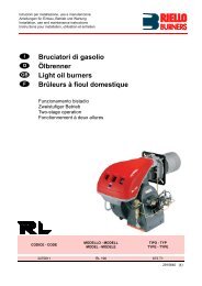
<strong>Gas</strong>-<strong>Gebläsebrenner</strong><br />
<strong>Brûleur</strong> <strong>gaz</strong> <strong>à</strong> <strong>air</strong> <strong>soufflé</strong><br />
<strong>Forced</strong> <strong>draught</strong> <strong>gas</strong> burner<br />
Einstufig<br />
Fonctionnement <strong>à</strong> 1 allure<br />
One stage operation<br />
CODE MODELL - MODELE - MODEL TYP - TYPE<br />
3755414 GS10 554T1<br />
2902045 (5)
<strong>Gas</strong>-GeblŠsebrenner<br />
GS10<br />
TECHNISCHE MERKMALE<br />
2045<br />
CODE<br />
1<br />
3755414<br />
Für <strong>Gas</strong> der 3. <strong>Gas</strong>familie (Flüssig<strong>gas</strong>) Umstellsatz anfordern.<br />
◆<br />
◆<br />
◆<br />
◆<br />
Der Brenner entspricht der Schutzart IP 40 gemäß EN 60529.<br />
CE Kennzeichnung gemäß der <strong>Gas</strong>geräterichtlinie 90/396/EWG; PIN 0063AP6680.<br />
D<br />
TYP<br />
Nennwärmebelastungsbereich 42 ¸ 116 kW – 36.000 ¸ 100.000 kcal/h<br />
<strong>Gas</strong><br />
(2. <strong>Gas</strong>familie)<br />
Unterer Heizwert 8 ¸<br />
Gemäß Richtlinien: EMV 89/336/EWG, Niederspannungsrichtlinie 73/23/EWG,<br />
Maschinenrichtlinie 89/392/EWG und Wirkungsgradrichtlinie 92/42/EWG.<br />
<strong>Gas</strong>strecke gemäß der Euronorm EN 676.<br />
12 kWh/m3<br />
– 7.000 ¸<br />
Druck Min. 10 mbar – Max. 35 mbar<br />
Netzanschluß Einphase 230V ± 10%<br />
Motor 230V / 0,7A<br />
Kondensator 2<br />
mF<br />
10.340 kcal/m3<br />
554T1<br />
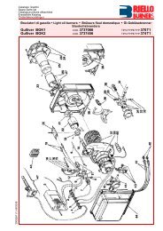
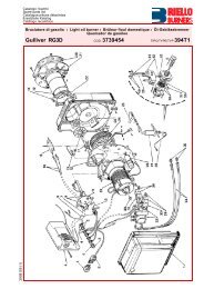
BEMERKUNG<br />
Die mitgelieferten Zubehörteile Kabeldurchführung (5) und Schraube (6) für Befestigung der<br />
Haube werden auf der gleichen Seite der <strong>Gas</strong>strecke installiert.<br />
~<br />
50Hz<br />
Zündtransformator Primär 230V / 1,8A – Sekundär 8 kV – 30 mA<br />
Leistungsaufnahme 0,13 kW<br />
LAND<br />
GASKATEGORIE<br />
IT - AT - GR - DK - SE GB - IE DE LU<br />
1 – Luftklappen<br />
2 – Luftklappenbefestigungsschrauben<br />
3 – 7 - polige Steckdose für<br />
Netzanschluß und Regelung<br />
4 – 6 - polige Steckdose für <strong>Gas</strong>strecke<br />
5 – Kabeldurchführung<br />
6 – Schraube für Befestigung<br />
der Haube<br />
7 – Störabschaltungssignal<br />
mit Entstörtaste<br />
II2H3B/P II2H3P II2ELL3B/P II2E3B/P<br />
7<br />
6<br />
5<br />
4<br />
Abb. 1<br />
3<br />
D5168<br />
1<br />
2<br />
2
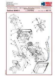
ABMESSUNGEN<br />
160<br />
* Flammrohr - Verlängerung.<br />
MITGELIEFERTES ZUBEHÖR<br />
BEFESTIGUNG AM KESSEL<br />
2045<br />
45°<br />
Flansch Brenner<br />
ø 185<br />
45°<br />
11<br />
262<br />
Rp 3/4<br />
305 110 347<br />
188<br />
* 170<br />
130 33 61<br />
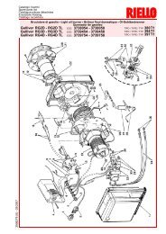
Den Brennkopf, durch Lösen der Mutter (1), vom Brenner<br />
trennen und den Maschinenteil (A) abnehmen.<br />
Den Teil (B) an der Kesseltür (2) befestigen, unter<br />
Zwischenlegung der Flanschdichtung (3).<br />
1 3 2<br />
A B<br />
D5179<br />
2<br />
D<br />
204<br />
142<br />
ø 105<br />
Menge Beschreibung<br />
1<br />
4<br />
1<br />
1<br />
1<br />
1<br />
7 - poliger Stecker<br />
Schrauben mit Mutter<br />
Flanschdichtung<br />
Schraube für Befestigung der Haube<br />
Kabeldurchführung<br />
Schwenkgelenk<br />
MONTAGE DES GELENKES<br />
S7392<br />
D5169
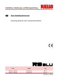
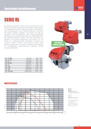
ARBEITSBEREICH<br />
PRÜFKESSEL<br />
Das Arbeitsfeld wurde auf einem Prüfkessel, gemäß den Normen DIN 4788 und EN 676, erzielt.<br />
HANDELSÜBLICHE HEIZKESSEL<br />
Die Abstimmung Brenner-Kessel ist ohne Probleme, wenn der Kessel der Euronorm EN 303 entspricht<br />
und die Abmessungen der Brennkammer mit Euronorm EN 676 übereinstimmen. Wenn der<br />
Brenner mit einem Heizkessel kombiniert werden soll, der nicht der Euronorm EN 303 und der<br />
EN 676 entspricht, müssen die technischen Daten aufeinander abgestimmt werden. Die Kesseldaten<br />
beim Hersteller abfragen.<br />
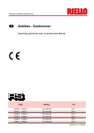
VOM GASDRUCK ABHÄNGIGE BRENNERLEISTUNG<br />
Bei einem an dem Verbindungsrohr gemessenen Druck von 5,8 mbar, mit einem feuerseitigen Widerstand<br />
von 0 mbar und mit <strong>Gas</strong> G20 - unterer Heizwert = 10 kWh/m3<br />
( 8.570 kcal/m3)<br />
- erreicht man die<br />
Höchstleistung.<br />
2045<br />
Feuerraumwiderstand<br />
mbar<br />
<strong>Gas</strong>druck<br />
mbar<br />
1,6<br />
1,4<br />
1,2<br />
1,0<br />
0,8<br />
0,6<br />
0,4<br />
0,2<br />
0<br />
40<br />
7<br />
6<br />
5<br />
4<br />
3<br />
2<br />
1<br />
40<br />
50 60 70 80 90 100 110 120 kW<br />
40.000 50.000 60.000 70.000 80.000 90.000 100.000 kcal/h<br />
3<br />
D<br />
Leistung D5256<br />
50 60 70 80 90 100 110 120 kW<br />
40.000 50.000 60.000 70.000 80.000 90.000 100.000<br />
kcal/h<br />
Leistung D5257
GASZULEITUNGSSYSTEM<br />
1 – <strong>Gas</strong>zuleitung<br />
2 – Handabsperrschieber (zu Lasten vom Installateur)<br />
3 – <strong>Gas</strong>druckmanometer (zu Lasten vom Installateur)<br />
4 – Filter<br />
5 – <strong>Gas</strong>druckwächter<br />
6 – Sicherheitsventil<br />
DIE GASSTRECKE ENTSPRECHEND EURONORM EN 676<br />
Die <strong>Gas</strong>strecke muß der Euronorm EN 676 entsprechen und wird extra bestellt. Die Einregulierung<br />
wird entsprechend der beigefügten Betriebsanleitung durchgeführt.<br />
EINSTELLUNG DES FLAMMENFÜHLERS UND DER ZÜNDELEKTRODE<br />
2045<br />
MULTIBLOC<br />
DUNGS<br />
ANSCHLÜSSE<br />
GASSTRECKE BRENNER<br />
MBDLE 405 B01 Rp 1/2 Rp 3/4<br />
GEBRAUCH<br />
Erd<strong>gas</strong> £ 80 kW<br />
Flüssig<strong>gas</strong><br />
MBDLE 407 B01 Rp 3/4 Rp 3/4 Erd<strong>gas</strong><br />
Flüssig<strong>gas</strong><br />
Flammen-<br />
Fühler<br />
D5104<br />
1<br />
~ 40 mm<br />
2 3 M1 4 5 6 7 8<br />
Zündelektrode<br />
Verteilerdüse<br />
ACHTUNG 2 ¸ 3 mm<br />
4<br />
D<br />
M2<br />
7 – <strong>Gas</strong>druckregler<br />
8 – Einstellventil<br />
M1 – Messung, Anschlußdruck<br />
M2 – Messung, Brenner- Kopfdruck<br />
RIELLO GASSTRECKE<br />
(alternativ)<br />
D5050<br />
◆ Filter DUNGS GF 507/1<br />
◆ <strong>Gas</strong>druckregler DUNGS FRS 207/1<br />
◆ <strong>Gas</strong>druckwächter DUNGS GW 50 A4<br />
◆ Einstellventile Riello (R.B.L.)<br />
487SE und 488SE<br />
2,2<br />
=<br />
Flammenfühler<br />
Zündelektrode<br />
=
Flammenfühler<br />
Zündelektrode<br />
2<br />
2045<br />
1<br />
4<br />
2<br />
P<br />
P<br />
Luftdruckwächter<br />
M<br />
~<br />
3<br />
1<br />
Zündtrafo<br />
Luftklappenstellmotor<br />
Funk-Enstörhilfe<br />
Schwarz<br />
Braun<br />
Blau<br />
ELEKTRISCHES SCHALTSCHEMA<br />
(Werks - Ausführung)<br />
4<br />
Kabelverbinder<br />
13 6 10<br />
3 STEUERGERÄT 7<br />
2<br />
8<br />
508SE 1<br />
A<br />
12<br />
16 15 17<br />
5 9 B<br />
3 2 1 N Ph B4 S3 T2 T1<br />
5 D<br />
N L1<br />
6 - polige Steckdose 7 - polige Steckdose<br />
Weiss<br />
Braun<br />
Schwarz<br />
D5126<br />
Blau<br />
M<br />
~<br />
Motor<br />
Kondensator<br />
Brenner-Erdung
ANMERKUNGEN<br />
2045<br />
ELEKTRISCHE ANSCHLÜSSE<br />
(Vom Installateur auszuführen)<br />
– Nulleiter und Phase nicht vertauschen und das o.g. elektrische Schema genau verbinden.<br />
– Drahtquerschnitt: min. 1 mm2.<br />
– Für eine gute Erdung sorgen.<br />
– Die Regelabschaltung des Brenners, durch Öffnen des Kesselthermostaten, und die Störabschaltung,<br />
durch Trennen des Flammenfühlerkabels, überprüfen.<br />
– Die vom Installateur ausgeführten elektrischen Verbindungen müssen den Landesbestimmungen<br />
entsprechen.<br />
PROGRAMMABLAUF DES BRENNERSTARTS<br />
Thermostat<br />
Motor<br />
Zündtransformator<br />
Magnetventil<br />
Flamme<br />
Störsignal<br />
6 - polige Stecker 7 - polige Stecker<br />
3 2 1 N Ph<br />
Schwarz<br />
1 2 3 1 2 3<br />
3s<br />
VS V1<br />
Normal<br />
38s<br />
Grau<br />
P<br />
GAS<br />
Sollte die Flamme während des Betriebes erlöschen, erfolgt eine Störabschaltung innerhalb<br />
1 Sekunde .<br />
6 D<br />
B4 S3 T2 T1 N L1<br />
h<br />
T<br />
EINST.<br />
6A<br />
N<br />
L<br />
PE<br />
TS<br />
230V ~ 50Hz D5128<br />
Störung wegen fehlender<br />
Flammenbildung<br />
3s 38s 3s<br />
D5139
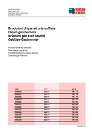
LUFTKLAPPENEINSTELLUNG<br />
Die bewegliche Klappe (1) wird durch den StellMotor<br />
(2) betrieben und garantiert die vollständige Öffnung<br />
der Luftansaugöffnung.<br />
Der Luftdurchsatz wird durch die Luftklappe (3) einreguliert.<br />
Zu diesem Zweck müssen zuvor die<br />
Schrauben (4) gelöst werden.<br />
Hat man die optimale Einstellung erreicht, dann die<br />
Schrauben (4) festschrauben, um die freie Bewegung<br />
der Klappe (1) sicherzustellen.<br />
Die Luftklappe (3) wird im Werk auf Position 3 eingestellt.<br />
EINSTELLUNG<br />
DES BRENNERKOPFES<br />
Die Schraube (A) lockern, den <strong>Gas</strong>kopf (B) so verschieben,<br />
daß die rückwärtige Fläche (C) des Verbindungsrohres<br />
mit der gewünschten Skala-<br />
Einstellzahl übereinstimmt.<br />
Die Schraube (A) wieder festziehen.<br />
Beispiel:<br />
Der Brenner ist auf einem Kessel von 81 kW installiert.<br />
Bei einem Wirkungsgrad von 90% sollte der<br />
Brenner ca. 90 kW abgeben. Aus dem Diagramm<br />
ergibt sich, daß für diese Leistung die Einstellzahl 3<br />
festzulegen ist.<br />
2045<br />
kcal/h kW<br />
100.000<br />
90.000<br />
80.000<br />
70.000<br />
60.000<br />
50.000<br />
40.000<br />
120<br />
110<br />
100<br />
90<br />
80<br />
70<br />
60<br />
50<br />
40<br />
0 1 2 3<br />
Das ist ein orienterendes Diagramm; und es muß nur für eine anfängliche Einstellung benutzen<br />
werden. Um einen guten Betrieb des Luftdruckwächters zu sichern, wird es notwendig die Öffnung<br />
des Brennerkopfes zu reduzieren. (Einstellzahl in Richtung 0 Stellung) .<br />
7 D<br />
C<br />
A<br />
B<br />
1<br />
4<br />
4 5<br />
S7015<br />
D5036<br />
Einstellzahl D5258<br />
2<br />
3<br />
4
EINSTELLUNG DER VERBRENNUNG<br />
In Konformität mit der Wirkungsgradrichtlinie 92/42/EWG müssen die Anbringung des Brenners<br />
am Heizkessel, die Einstellung und die Inbetriebnahme unter Beachtung der Betriebsanleitung der<br />
Heizkessels ausgeführt werden, einschließlich Kontrolle der Konzentration von CO und CO 2 in<br />
den Ab<strong>gas</strong>en, ihrer Temperatur und der mittlenen Kesseltemperatur.<br />
Der Brenner muß gemäß untenstehender Tabelle auf die jeweils vorhandene <strong>Gas</strong>art eingestellt<br />
werden:<br />
IONISATIONSSTROM<br />
Der Betrieb des Steuergerätes erfordert einen Strom von mindenstens 3 mA.<br />
Da der Brenner einen weitaus höheren Strom vorsieht, sind normalerweise keine Kontrollen nötig.<br />
Wenn aber der Ionisationsstrom gemessen werden soll, muß das Ionisationskabel getrennt und<br />
ein Gleichstrom - Mikroamperometer zwischengeschaltet werden.<br />
LUFTDRUCKWÄCHTER:<br />
Während der Einregulierung des <strong>Gas</strong>brenners wird der Luftdruckwächter<br />
auf 0 gestellt.<br />
Ist die Einregulierung abgeschlossen, wird der Luftdruck einreguliert.<br />
Die Regulierskala langsam im Uhrzeigersinn drehen bis der<br />
Brenner abschaltet. Dann die Regulierskala entgegengesetz, um<br />
einen Wert zurückdrehen bis der Brenner wieder einschaltet.<br />
Mit dieser Einstellung den Brennerstart mehrmals wieder holen<br />
und bei Bedarf den Luftdruckwächter nachregulieren.<br />
Achtung:<br />
Der Luftdruckwächter muß nach Norm den Brenner abschalten wenn der CO-Wert 1% (10.000 ppm)<br />
überschreitet. Um dies zu überprüfen, wird ein Ab<strong>gas</strong>analysegerät angeschlossen und die Luftansangung<br />
am Brenner zugehalten. Der Brenner muß abschalten bei CO-Wert
SCHWIERIGKEITEN BEIM ANLAUF UND IHRE URSACHEN<br />
BEMERKUNG: Sollten, trotz der obengennanten Maßnahmen, Schwierigkeiten beim Anlauf<br />
bleiben, überprüfen, daß keine Kurzschlüsse in den Leitungen des Motors, der<br />
<strong>Gas</strong>magnetventile, des Zündtransformators und in den äußeren Signalisierungen<br />
vorhanden sind, bevor man das Steuergerät ersetzt.<br />
FEHLVERHALTEN<br />
Störabschaltung wegen : – Erlöschen der Flamme<br />
: – Der Fühler macht Masse<br />
: – Öffnen des Luftdruckwäckters<br />
Brennerstillstand wegen : – Öffnen des <strong>Gas</strong>druckwächters<br />
2045<br />
SCHWIERIGKEITEN URSACHEN<br />
Die Vorspülung erfolgt<br />
planmässig, die Flamme<br />
zündet, aber innerhalb<br />
von 3 Sekunden nach<br />
Brenneranlauf erfolgt eine<br />
Störabschaltung.<br />
Nach der Vorspülphase<br />
erfolgt die Störabschaltung<br />
des Brenners, da die<br />
Flamme nicht zündet.<br />
Die Störabschaltung erfolgt<br />
während der Vorspülphase.<br />
Der Brenner läuft beim<br />
Schließen des Thermostaten<br />
nicht an.<br />
Der Brenner wiederholt<br />
unaufhörlich das Anlaufprogramm,<br />
ohne daß eine<br />
Störabschaltung erfolgt.<br />
Der Ionisationsfühler macht Masse oder der Fühler hat keinen Kontakt<br />
mit der Flamme oder die Kabelverbindung des Fühlers mit dem<br />
Steuergerät ist unterbrochen oder die Verbindung ist gegen die Erdung<br />
hin nicht sachgemäß isoliert.<br />
Der Ionisationsstrom ist schwach (geringer als 3 mA).<br />
Die Einstellung des <strong>Gas</strong>druckwächters liegt zu nahe am Betriebsdruck<br />
.<br />
Die Elektromagnetventile lassen nicht genug <strong>Gas</strong> durch (geringer<br />
Druck in der <strong>Gas</strong>zuleitung).<br />
Die Elektromagnetventile sind defekt.<br />
Die Zündung ist fehlerhaft.<br />
<strong>Gas</strong>leitung wurde nicht entlüftet.<br />
Der Luftdruckwächter schaltet nicht um: er ist defekt oder der Luftdruck<br />
ist zu gering (Brennerkopf ist schlecht eingestellt).<br />
Die Flamme wird simuliert (oder besteht tatsächlich).<br />
Es ist kein <strong>Gas</strong> vorhanden.<br />
Der <strong>Gas</strong>drückwächter schließt nicht : er ist schlecht eingestellt.<br />
Der Luftdrückwächter ist schlecht eingestellt.<br />
Der Luftklappenmotor ist defekt.<br />
Es handelt sich hierbei um eine besondere Unregelmäßigkeit, die<br />
durch die Tatsache hervorgerufen wird,daß der <strong>Gas</strong>druck in den Leitungen<br />
fast mit dem Wert auf welchen der <strong>Gas</strong>druckwächter eingestellt<br />
ist übereinstimmt; die plötzlich auftretende Druckminderung,<br />
welche durch das Öffnen des Ventils hervorgerufen wird verursacht<br />
die zeitlich begrenzte Öffnung des Druckwächters.<br />
Diese Öffnung ist zeitlich begrenzt, da sich das Ventil sofort wieder<br />
schließt und der Motor anhält.<br />
Nun beginnt der Druck wieder anzusteigen, der <strong>Gas</strong>druckwächter<br />
schließt erneut und sorg somit dafür, daß Anlaufprogramm wiederholt<br />
wird - dies geschieht ständig.<br />
Um dieses Fehlverhalten zu vermeiden, muß die Druckeinstellung<br />
des Druckwächters korrigiert werden.<br />
9 D
Bržleur <strong>gaz</strong> ˆ <strong>air</strong> soufߎ<br />
GS10 CODE<br />
DONNEES TECHNIQUES<br />
Pour <strong>gaz</strong> de la famille 3 (GPL), kit sur demande.<br />
◆<br />
◆<br />
◆<br />
◆<br />
2045<br />
1<br />
3755414<br />
<strong>Brûleur</strong> conforme au degré de protection IP 40 selon EN 60529.<br />
F<br />
TYPE<br />
Puissance thermique 42 ¸ 116 kW – 36.000 ¸ 100.000 kcal/h<br />
Gaz naturel<br />
(Famille 2)<br />
Pci 8 ¸<br />
Marquage CE conforme <strong>à</strong> la Directive Appareils <strong>à</strong> Gaz 90/396/CEE; PIN 0063AP6680.<br />
554T1<br />
<strong>Brûleur</strong> avec label CE conformément aux directives CEE: EMC 89/336/CEE, Basse Tension 73/23/CEE,<br />
Machines 89/332/CEE et rendement 92/42/CEE.<br />
Rampe <strong>gaz</strong> conforme <strong>à</strong> EN 676.<br />
12 kWh/m3<br />
– 7.000 ¸<br />
Pression min. 10 mbar – max. 35 mbar<br />
10.340 kcal/m3<br />
Alimentation électrique monophasée, 230V ± 10% ~ 50Hz<br />
Moteur 230V / 0,7 A<br />
Condensateur 2<br />
mF<br />
Transformateur d’allumage prim<strong>air</strong>e 1,8A / 230V – second<strong>air</strong>e 8 kV / 30 mA<br />
Puissance électrique absorbée 0,13 kW<br />
PAYS<br />
CATEGORIE GAZ<br />
1 – Volets d’<strong>air</strong><br />
2 – Vis blocage volet d’<strong>air</strong><br />
3 – Prise alimentation et<br />
télécommandes <strong>à</strong> 7 pôles<br />
4 – Prise rampe <strong>gaz</strong> <strong>à</strong> 6 pôles<br />
5 – Presse-étoupe<br />
6 – Vis pour fixage capot<br />
7 – Bouton de réarmement avec<br />
signalisation de sécurité<br />
IT - AT - GR - DK - SE GB - IE DE LU<br />
II2H3B/P II2H3P II2ELL3B/P II2E3B/P<br />
7<br />
6<br />
NOTE<br />
Le presse-étoupe (5) et la vis de fixation pour capot (6), livrés avec le brûleur, doivent être montés<br />
du même côté de la rampe <strong>gaz</strong>.<br />
5<br />
4<br />
Fig. 1<br />
3<br />
D5168<br />
1<br />
2<br />
2
DIMENSIONS<br />
160<br />
* Tête de combustion longue sur demande.<br />
MATERIEL COMPLEMENTAIRE<br />
FIXATION A LA CHAUDIERE<br />
2045<br />
45°<br />
Bride <strong>Brûleur</strong><br />
ø 185<br />
45°<br />
11<br />
262<br />
Rp 3/4<br />
305 110 347<br />
188<br />
* 170<br />
130 33 61<br />
Enlever ensuite la tête de combustion du brûleur<br />
en desserrant l’écrou (1), ôter le groupe (A).<br />
Fixer le groupe (B) <strong>à</strong> la plaque (2) de la chaudière,<br />
interposer le joint isolant (3) livré avec le brûleur.<br />
1 3 2<br />
A B<br />
D5179<br />
2<br />
F<br />
204<br />
142<br />
ø 105<br />
Quantité Dénomination<br />
1<br />
4<br />
1<br />
1<br />
1<br />
1<br />
Fiche <strong>à</strong> 7 pôles<br />
Vis avec écrous<br />
Joint isolant<br />
Vis pour fixation capot<br />
Presse-étoupe<br />
Charnière<br />
MONTAGE CHARNIERE<br />
S7392<br />
D5169
PLAGE D’UTILISATION<br />
CHAUDIERE D’ESSAI<br />
La plage d’utilisation a été obtenue avec une chaudière d’essai conforme aux normes DIN 4788 et EN 676.<br />
CHAUDIERE COMMERCIALE<br />
L’accouplement brûleur/chaudière ne produit pas de problèmes si la chaudière est conforme <strong>à</strong> la<br />
norme EN 303 et si la chambre de combustion a des dimensions simil<strong>air</strong>es <strong>à</strong> celles prévues dans<br />
la norme EN 676.<br />
Par contre, si le brûleur doit être accouplé <strong>à</strong> une chaudière commerciale qui n’est pas conforme <strong>à</strong><br />
la norme EN 303 ou dont les dimensions de la chambre de combustion sont plus petites que<br />
celles indiquées dans la norme EN 676, consulter le fabriquant.<br />
CORRELATION ENTRE PRESSION DU GAZ ET PUISSANCE<br />
Pour obtenir la puissance maxi, il faut avoir 5,8 mbar mesurée au manchon avec chambre de combustion<br />
<strong>à</strong> 0 mbar et <strong>gaz</strong> G20 - Pci = 10 kWh/m3<br />
( 8.570 kcal/m3).<br />
2045<br />
Pression dans la chambre de<br />
combustion en mbar<br />
Pression <strong>gaz</strong><br />
mbar<br />
1,6<br />
1,4<br />
1,2<br />
1,0<br />
0,8<br />
0,6<br />
0,4<br />
0,2<br />
0<br />
40<br />
7<br />
6<br />
5<br />
4<br />
3<br />
2<br />
1<br />
40<br />
50 60 70 80 90 100 110 120 kW<br />
40.000 50.000 60.000 70.000 80.000 90.000 100.000 kcal/h<br />
3<br />
F<br />
Puissance brûleur D5256<br />
50 60 70 80 90 100 110 120 kW<br />
40.000 50.000 60.000 70.000 80.000 90.000 100.000<br />
kcal/h<br />
Puissance brûleur D5257
SCHEMA ALIMENTATION DU GAZ<br />
RAMPE GAZ SELON EN 676<br />
2045<br />
MULTIBLOC<br />
DUNGS<br />
CONNEXIONS<br />
RAMPE BRULEUR<br />
MBDLE 405 B01 Rp 1/2 Rp 3/4<br />
1<br />
2 3 M1 4 5 6 7 8<br />
1 – Conduit arrivée du <strong>gaz</strong><br />
2 – Robinet de barrage (<strong>à</strong> charge de l’installateur)<br />
3 – Manomètre pression du <strong>gaz</strong> (<strong>à</strong> charge de l’installateur)<br />
4 – Filtre<br />
5 – Pressostat <strong>gaz</strong><br />
6 – Vanne de sécurité<br />
7 – Régulateur de pression<br />
EMPLOI<br />
Gaz naturel £ 80 kW<br />
GPL<br />
MBDLE 407 B01 Rp 3/4 Rp 3/4 Gaz naturel et GPL<br />
La rampe <strong>gaz</strong> est fournie <strong>à</strong> part, voir les notices jointes pour son réglage.<br />
POSITIONNEMENT ELECTRODE - SONDE<br />
D5104<br />
Sonde<br />
~ 40 mm<br />
Electrode d’allumage<br />
Injecteur<br />
ATTENTION 2 ¸ 3 mm<br />
4<br />
F<br />
M2<br />
ALTERNATIVEMENT<br />
RAMPE GAZ RIELLO AVEC:<br />
D5050<br />
8 – Vanne de réglage<br />
M1 – Prise pour le contrôle de la<br />
pression <strong>gaz</strong> <strong>à</strong> l’alimentation<br />
M2 – Prise pour le contrôle de la<br />
pression <strong>à</strong> la tête<br />
◆ Filtre DUNGS GF 507/1<br />
◆ Régulateur de pression DUNGS FRS 207/1<br />
◆ Pressostat DUNGS GW 50 A4<br />
◆ Vannes Riello (R.B.L.) 487SE et 488SE<br />
2,2<br />
=<br />
Sonde<br />
Electrode<br />
=
2<br />
2045<br />
Sonde<br />
1<br />
4<br />
2<br />
P<br />
P<br />
Pressostat <strong>air</strong><br />
Moteur<br />
ouvre-volet d’<strong>air</strong><br />
M<br />
~<br />
Antiparasite<br />
Transf. d’allumage<br />
3<br />
1<br />
Noir<br />
Marron<br />
Bleu<br />
INSTALLATION ELECTRIQUE<br />
(exécutée en usine)<br />
4<br />
Connecteur<br />
13 6 10<br />
3 BOITE DE CONTROLE 7<br />
2<br />
8<br />
508SE 1<br />
A<br />
12<br />
16 15 17<br />
5 9 B<br />
3 2 1 N Ph B4 S3 T2 T1<br />
5 F<br />
N L1<br />
Prise 6 pôles Prise 7 pôles<br />
Blanc<br />
Marron<br />
Noir<br />
D5126<br />
Bleu<br />
M<br />
~<br />
Moteur<br />
Condensateur<br />
Terre brûleur
NOTES<br />
2045<br />
RACCORDEMENTS ELECTRIQUES<br />
(exécutés par l’installateur)<br />
– Ne pas inverser le neutre et la phase et respecter exactement le schéma indiqué.<br />
– Section conducteurs: 1 mm2. – Réaliser un bon raccordement <strong>à</strong> la terre.<br />
– Vérifier l’arrêt du brûleur en ouvrant le thermostat de chaudière et la mise en sécurité en<br />
débranchant le connecteur inséré dans le fil rouge de la sonde de révélation flamme, extérieur<br />
<strong>à</strong> la boîte de contrôle.<br />
– Les branchements électriques exécutés par l’installateur doivent respecter le règlement en<br />
vigueur dans le Pays.<br />
CYCLE DE DEMARRAGE<br />
Thermostat<br />
Moteur<br />
Transf. d’allumage<br />
Vannes<br />
Flamme<br />
Sécurité<br />
3 2 1 N Ph<br />
Noire<br />
1 2 3 1 2 3<br />
3s<br />
Fiche 6 pôles Fiche 7 pôles<br />
VS V1<br />
Grise<br />
P<br />
GAZ<br />
Si la flamme s’éteint durant le fonctionnement, le brûleur se met en sécurité en moins d’une<br />
seconde.<br />
6 F<br />
B4 S3 T2 T1 N L1<br />
h<br />
T<br />
REG.<br />
6A<br />
N<br />
L<br />
PE<br />
TS<br />
230V ~ 50Hz D5128<br />
Normal Mise en sécurité par défaut d’allumage<br />
38s<br />
3s 38s 3s<br />
D5139
REGLAGE VOLET D’AIR<br />
Le volet d’<strong>air</strong> mobile (1), commandé par le moteur<br />
(2), donne l’ouverture complète de la boîte d’aspiration<br />
de l’<strong>air</strong>.<br />
La régulation du débit d’<strong>air</strong> se fait par le volet fixe<br />
(3), après avoir desserré les vis (4).<br />
Une fois obtenue la régulation optimale, bloquer le<br />
volet d’<strong>air</strong> par les vis (4); il faut les visser complètement<br />
pour assurer le libre mouvement du volet<br />
mobile (1).<br />
Le volet d’<strong>air</strong> est réglé en usine sur la position 3.<br />
REGLAGE TETE DE COMBUSTION<br />
Desserrer la vis (A), déplacer le coude (B) de façon<br />
<strong>à</strong> ce que la surface postérieure du manchon (C) corresponde<br />
avec l’encoche désirée. Serrer la vis (A).<br />
Exemple:<br />
Le brûleur est monté sur une chaudière de 81 kW.<br />
Supposant un rendement de 90%, le brûleur devra<br />
débiter environ 90 kW.<br />
Le diagramme démontre que pour cette puissance<br />
le réglage doit être exécuté sur l’encoche 3.<br />
2045<br />
kcal/h kW<br />
100.000<br />
90.000<br />
80.000<br />
70.000<br />
60.000<br />
50.000<br />
40.000<br />
120<br />
110<br />
100<br />
90<br />
80<br />
70<br />
60<br />
50<br />
40<br />
D5258<br />
0 1 2 3<br />
Le diagramme est indicatif et doit être utilisé pour une régulation initiale.<br />
Pour garantir le bon fonctionnement du pressostat <strong>air</strong>, il peut être nécess<strong>air</strong>e de réduire l’ouverture<br />
de la tête de combustion (encoche vers la position. 0).<br />
7 F<br />
C<br />
A<br />
B<br />
1<br />
4<br />
4 5<br />
S7015<br />
N° encoche<br />
D5036<br />
2<br />
3<br />
4
REGLAGE DE LA COMBUSTION<br />
Conformément <strong>à</strong> la Directive rendement 92/42/CEE, suivre les indications du manuel de la chaudière<br />
pour monter le brûleur, effectuer le réglage et l’essai, contrôler la concentration de CO et<br />
CO 2 , dans les fumées, leur température et celle moyenne de l’eau de la chaudière.<br />
Il est conseillé de régler le brûleur selon les indications reprises dans le tableau et en fonction du type<br />
de <strong>gaz</strong> utilisé:<br />
COURANT D’IONISATION<br />
L’intensité minimum nécess<strong>air</strong>e au bon fonctionnement de la boîte de contrôle est de 3 mA.<br />
Le brûleur fonctionne avec une intensité nettement supérieure, ne nécessitant aucun contrôle.<br />
Cependant, si l’on veut mesurer le courant d’ionisation il faut ouvrir le connecteur inséré dans le<br />
câble rouge de la sonde et insérer un micro-ampèremètre.<br />
PRESSOSTAT AIR<br />
Effectuer le réglage du pressostat <strong>air</strong> après toutes les autres<br />
régulations du brûleur avec le pressostat <strong>air</strong> réglé en début<br />
d’échelle.<br />
Avec le brûleur fonctionnant au minimum de puissance, augmenter<br />
la pression du réglage en tournant lentement le bouton gradué<br />
dans le sens hor<strong>air</strong>e jusqu’<strong>à</strong> l’arrêt du brûleur.<br />
Puis tourner dans le sens inverse le même bouton d’une graduation<br />
et répéter le démarrage du brûleur pour vérifier le bon fonctionnement.<br />
Si le brûleur se met en sécurité, tourner dans le même sens d’une<br />
1/2 graduation.<br />
Attention:<br />
Conformément <strong>à</strong> la norme, le pressostat <strong>air</strong> doit intervenir quand le CO dans les produits de combustion<br />
dépasse 1% (10.000 ppm).<br />
Pour ce contrôle, insérer un analyseur de combustion dans la cheminée, obturer lentement l’aspiration<br />
d’<strong>air</strong> et vérifier que le brûleur se met en sécurité avant que le pourcentage de CO dans les<br />
produits de combustion atteigne 1%.<br />
2045<br />
EN 676 Excès d’<strong>air</strong> au maximum: l £ 1,2 – Excès d’<strong>air</strong> au minimum: l £ 1,3<br />
GAZ<br />
Réglage CO2 %<br />
l = 1,2 l = 1,3<br />
CO2 max<br />
0 % O2 CO<br />
mg/kWh<br />
NOx mg/kWh<br />
G 20 9,7 9,0 11,7 £ 100 £ 170<br />
G 25 9,5 8,8 11,5 £ 100 £ 170<br />
G 30 11,6 10,7 14,0 £ 100 £ 230<br />
G 31 11,4 10,5 13,7 £ 100 £ 230<br />
Bornier boîte<br />
de contrôle<br />
10<br />
Connecteur<br />
8 F<br />
Sonde<br />
D5049<br />
D5006
DIFFICULTE DE MISE EN ROUTE ET SES CAUSES<br />
2045<br />
DIFFICULTES CAUSES<br />
Le brûleur exécute normalement<br />
la préventilation, la<br />
flamme s’allume, puis le brûleur<br />
se met en sécurité 3 secondes<br />
après l’allumage.<br />
Le brûleur se met en sécurité<br />
après la phase de préventilation<br />
car la flamme ne s’allume<br />
pas.<br />
Le brûleur se met en sécurité<br />
pendant la phase de préventilation.<br />
Le brûleur ne démarre pas <strong>à</strong><br />
la fermeture du thermostat.<br />
Le brûleur répète en continu<br />
le cycle de démarrage sans<br />
se mettre en sécurité.<br />
N.B.: S’il demeure des difficultés de démarrage même après les interventions mentionnées<br />
ci-dessus, vérifier avant de remplacer la boîte de contrôle s’il n’y a pas de court-circuits sur<br />
les lignes du moteur, des vannes <strong>gaz</strong>, du transformateur d’allumage et des signalisations<br />
extérieures.<br />
ANOMALIES EN FONCTIONNEMENT<br />
Mise en sécurité par : – disparition de la flamme<br />
– sonde <strong>à</strong> la masse<br />
– ouverture du pressostat <strong>air</strong><br />
Arrêt par. . . . . . . . . . : – ouverture du pressostat <strong>gaz</strong><br />
La sonde d’ionisation est <strong>à</strong> la masse, ou n’est pas en contact avec la<br />
flamme; ou sa connection avec la boîte de contrôle est interrompue,<br />
ou bien il y a défaut d’isolement avec la masse.<br />
Le courant d’ionisation est faible (au-dessous de 3 mA).<br />
Le pressostat <strong>gaz</strong> est réglé trop proche de la pression de fonctionnement.<br />
Les vannes laissent passer trop peu de <strong>gaz</strong> (basse pression en réseau).<br />
Les vannes sont défectueuses.<br />
L’arc électrique manque ou est irrégulier.<br />
L’<strong>air</strong> n’a pas été évacué de la conduite.<br />
Le pressostat <strong>air</strong> n’etablit pas le contact; il est défectueux ou bien la<br />
pression <strong>air</strong> est trop basse (tête mal réglée).<br />
Il existe simulation de flamme (ou la flamme est réellement présente).<br />
Défaut de <strong>gaz</strong>.<br />
Le pressostat <strong>gaz</strong> ne ferme pas le contact; il est mal réglé.<br />
Le pressostat <strong>air</strong> est commuté en position de fonctionnement.<br />
Le moteur du volet d’<strong>air</strong> est défectueux.<br />
Il s’agit d’une irrégularité tout <strong>à</strong> fait particulière, due au fait que la<br />
pression du <strong>gaz</strong> est trop proche de la valeur sur laquelle le pressostat<br />
<strong>gaz</strong> est réglé.<br />
Ainsi la soudaine diminution de pression, dès que la vanne s’ouvre,<br />
provoque l’ouverture, pendant un instant, du pressostat; comme la<br />
vanne se referme immédiatement, la pression tend <strong>à</strong> augmenter, le<br />
pressostat se referme et fait répéter la mise en route du brûleur, et<br />
ainsi de suite.<br />
On peut y remédier en diminuant le réglage de la pression du<br />
pressostat.<br />
9 F
<strong>Forced</strong> <strong>draught</strong> <strong>gas</strong> burner<br />
GS10 CODE 3755414<br />
TECHNICAL FEATURES<br />
For <strong>gas</strong> family 3 (LPG) ask for separate kit.<br />
◆<br />
◆<br />
◆<br />
◆<br />
2045<br />
The burner meets protection level of IP 40, EN 60529.<br />
1<br />
GB<br />
TYPE<br />
Thermal output 42 – 116 kW – 36,000 – 100,000 kcal/h<br />
<strong>Gas</strong><br />
(Family 2)<br />
CE marking according to <strong>Gas</strong> Appliance Directive 90/396/EEC; PIN 0063AP6680.<br />
554T1<br />
According to directives: EMC 89/336/EEC, Low Voltage 73/23/EEC, Machines 89/392/EEC and<br />
Efficiency 92/42/EEC.<br />
<strong>Gas</strong> train according to EN 676.<br />
Net heat value 8 – 12 kWh/m3<br />
– 7,000 – 10,340 kcal/m3<br />
Pressure min. 10 mbar – max. 35 mbar<br />
Electrical supply single phase, 230V ± 10% 50Hz<br />
Motor 230V / 0.7A<br />
Capacitor 2<br />
mF<br />
Ignition transformer primary 230V / 1.8A – secondary 8 kV / 30 mA<br />
Absorbed electrical power 0.13 kW<br />
COUNTRY<br />
GAS CATEGORY<br />
1 – Air-dampers<br />
2 – Screws for fixing the <strong>air</strong>-damper<br />
3 – 7 pole electrical controls plug and<br />
socket<br />
4 – 6 pole <strong>gas</strong>-train plug<br />
5 – Cable gland<br />
6 – Screw for fixing the cover<br />
7 – Lock-out lamp and reset button<br />
IT - AT - GR - DK - SE GB - IE DE LU<br />
II2H3B/P II2H3P II2ELL3B/P II2E3B/P<br />
7<br />
6<br />
NOTE<br />
The cable gland (5) and the screw for fixing the cover (6) supplied with the burner, must be fitted to<br />
the same side of the <strong>gas</strong> train.<br />
5<br />
4<br />
~<br />
Fig. 1<br />
3<br />
D5168<br />
1<br />
2<br />
2
DIMENSIONS<br />
160<br />
* Length available using an extended head kit.<br />
EQUIPMENT<br />
FIXING TO THE BOILER<br />
2045<br />
45°<br />
Flange Burner<br />
ø 185<br />
45°<br />
11<br />
262<br />
Rp 3/4<br />
305 110 347<br />
188<br />
* 170<br />
130 33 61<br />
Separate the combustion-head assembly from the<br />
burner body by removing nut (1) and removing group (A).<br />
Fix the head assembly group (B) to the boiler (2) insert<br />
the equipped insulating <strong>gas</strong>ket (3).<br />
1 3 2<br />
A B<br />
D5179<br />
2<br />
GB<br />
204<br />
142<br />
ø 105<br />
Quantity Description<br />
1<br />
4<br />
1<br />
1<br />
1<br />
1<br />
7 pin plug<br />
Screws with nuts<br />
Insulating <strong>gas</strong>ket<br />
Screw for fixing the cover<br />
Cable gland<br />
Hinge<br />
HINGE ASSEMBLY<br />
S7392<br />
D5169
WORKING RANGE<br />
TEST BOILER<br />
The working field has been defined according to DIN 4788 and EN 676 standards.<br />
COMMERCIAL BOILERS<br />
The burner-boiler matching is assured if the boiler is according to EN 303 and the combustion<br />
chamber dimensions are similar to those shown in the diagram EN 676.<br />
For applications where the boiler is not according to EN 303, or where the combustion chamber<br />
dimensions differ from those shown in EN 676, please consult the manufacturers.<br />
CORRELATION BETWEEN GAS PRESSURE AND BURNER OUTPUT<br />
To obtain the maximum output, a <strong>gas</strong> head pressure of 5.8 mbar is measured with the combustion<br />
chamber at 0 mbar using <strong>gas</strong> G20 with a net heat value of 10 kWh/m3<br />
( 8,570 kcal/m3)<br />
.<br />
2045<br />
Pressure in the combustion<br />
chamber – mbar<br />
<strong>Gas</strong> pressure<br />
mbar<br />
1.6<br />
1.4<br />
1.2<br />
1.0<br />
0.8<br />
0.6<br />
0.4<br />
0.2<br />
0<br />
40<br />
7<br />
6<br />
5<br />
4<br />
3<br />
2<br />
1<br />
40<br />
50 60 70 80 90 100 110 120 kW<br />
40,000 50,000 60,000 70,000 80,000 90,000 100,000 kcal/h<br />
3<br />
GB<br />
Burner output D5256<br />
50 60 70 80 90 100 110 120 kW<br />
40,000 50,000 60,000 70,000 80,000 90,000 100,000<br />
kcal/h<br />
Burner output D5257
LINE OF GAS-SUPPLY<br />
GAS TRAIN ACCORDING TO EN 676<br />
2045<br />
MULTIBLOC<br />
DUNGS<br />
1<br />
CONNECTION<br />
GAS TRAIN BURNER<br />
MBDLE 405 B01 Rp 1/2 Rp 3/4<br />
MBDLE 407 B01 Rp 3/4 Rp 3/4<br />
The <strong>gas</strong> train is supplied separately, for its adjustment see the enclosed instructions.<br />
POSITIONING ELECTRODE–PROBE<br />
2 3 M1 4 5 6 7 8<br />
1 – <strong>Gas</strong> supply pipe<br />
2 – Manual cock (charged to the installer)<br />
3 – <strong>Gas</strong> pressure gauge (charged to the installer)<br />
4 – Filter<br />
5 – <strong>Gas</strong> pressure switch<br />
6 – Safety valve<br />
D5104<br />
Probe<br />
~ 40 mm<br />
EMPLOY<br />
Natural <strong>gas</strong> £ 80kW<br />
LPG<br />
Natural <strong>gas</strong><br />
LPG<br />
Ignition electrode<br />
Diffuser<br />
4<br />
GB<br />
M2<br />
7 – Pressure governor<br />
8 – Adjusting valve<br />
M1 – <strong>Gas</strong>-supply pressure test point<br />
M2 – Pressure coupling test point<br />
WARNING 2 – 3 mm<br />
ALTERNATIVELY<br />
RIELLO GAS TRAIN WITH:<br />
◆ Filter DUNGS GF 507/1<br />
◆ Governor DUNGS FRS 207/1<br />
◆ Pressure switch DUNGS GW 50 A4<br />
◆ <strong>Gas</strong> valves Riello (R.B.L.) 487SE<br />
and 488SE<br />
2.2<br />
=<br />
Ionization probe<br />
Electrode<br />
=<br />
D5050
2<br />
2045<br />
Ionization probe<br />
1<br />
4<br />
2<br />
P<br />
P<br />
Air pressure switch<br />
M<br />
~<br />
Damper actuator<br />
Suppressor<br />
Ignition transformer<br />
3<br />
1<br />
Black<br />
Brown<br />
Blue<br />
BURNER ELECTRICAL WIRING<br />
(carried out in the factory)<br />
4<br />
Connector<br />
13 6 10<br />
3 CONTROL BOX 7<br />
2<br />
8<br />
508SE 1<br />
A<br />
12<br />
16 15 17<br />
5 9 B<br />
3 2 1 N Ph B4 S3 T2 T1<br />
5<br />
GB<br />
N L1<br />
6 pole socket 7 pole socket<br />
White<br />
Brown<br />
Black<br />
D5126<br />
Blue<br />
M<br />
~<br />
Motor<br />
Capacitor<br />
Burner earth
NOTES<br />
2045<br />
ELECTRICAL WIRING<br />
(to be carried-out by the installer)<br />
– Do not exchange the neutral with the phase and connect exactly the above wiring.<br />
– Wire of 1 mm2 section.<br />
– Carry out a safe earth connection.<br />
– Verify that the burner stops by operating the boiler control thermostats and that the burner goes<br />
lock out by separating the red ionisation probe lead connector.<br />
– The electric wiring carried out by the installer must be in compliance with the rules in force in<br />
the Country.<br />
BURNER START-UP CYCLE<br />
Thermostat<br />
Motor<br />
Ignition transformer<br />
Valve<br />
Flame<br />
Lock-out<br />
3 2 1 N Ph<br />
Black<br />
1 2 3 1 2 3<br />
3s<br />
6 pin plug 7 pin plug<br />
VS V1<br />
Grey<br />
When flame-failure occurs during working, shut down takes place within one second.<br />
P<br />
GAS<br />
6 GB<br />
B4 S3 T2 T1 N L1<br />
h<br />
T<br />
ADJUST.<br />
6A<br />
N<br />
L<br />
PE<br />
230V ~ 50Hz<br />
Normal Lock-out, due to light-failure<br />
38s<br />
TS<br />
D5128<br />
3s 38s 3s<br />
D5139
AIR DAMPER ADJUSTMENT<br />
The <strong>air</strong> damper (1) is operated by the motor (2)<br />
and assures that the <strong>air</strong> damper is fully open before<br />
the burner start cycle begins .<br />
The regulation of the <strong>air</strong> plate is made by adjusting<br />
the disc (3) after releasing the screws (4).<br />
When optimum setting is reached, tighten the<br />
screws (4), the <strong>air</strong> damper leaves the factory set<br />
at position 3.<br />
COMBUSTION-HEAD ADJUSTMENT<br />
Loose the screw (A), move the elbow (B) so that<br />
the rear plan of the coupling (C) coincides with the<br />
set point. Tight the screw (A).<br />
Example:<br />
The burner is installed on a 81 kW boiler with an<br />
efficiency of 90%, the burner input is about 90 kW<br />
using the diagram below, the combustion set<br />
point is 3.<br />
2045<br />
kcal/h kW<br />
100,000<br />
90,000<br />
80,000<br />
70,000<br />
60,000<br />
50,000<br />
40,000<br />
120<br />
110<br />
100<br />
90<br />
80<br />
70<br />
60<br />
50<br />
40<br />
0 1 2 3<br />
The diagram is to be used only for initial settings, to improve <strong>air</strong> pressure switch operation or<br />
improve combustion, it may be necessary to reduce this setting (set point toward position 0).<br />
7 GB<br />
C<br />
A<br />
B<br />
1<br />
4<br />
4 5<br />
D5036<br />
S7015<br />
Set point D5258<br />
2<br />
3<br />
4
COMBUSTION ADJUSTMENT<br />
In conformity with Efficiency Directive 92/42/EEC the application of the burner on the boiler,<br />
adjustment and testing must be carried out observing the instruction manual of the boiler, including<br />
verification of the CO and CO 2 concentration in the flue <strong>gas</strong>es, their temperatures and the<br />
average temperature of the water in the boiler.<br />
It is advisable to set the burner according to the type of <strong>gas</strong> used and following the indications of the<br />
table:<br />
IONIZATION CURRENT<br />
The minimum current required by the control box is 3 mA.<br />
The burner would normally have a higher current value than this, but if a check is required, open<br />
the connector fitted in the red probe lead and insert a microammeter as shown.<br />
AIR PRESSURE SWITCH<br />
The <strong>air</strong> pressure switch is set after all other adjustments have<br />
been made. Begin with the switch at the lowest setting.<br />
With the burner working at the minimum output, adjust the dial<br />
clockwise, increasing its value until the burner shuts down. Now<br />
reduce the value by one set point, turning the dial anti-clockwise.<br />
Check for reliable burner operation, if the burner shuts down, reduce<br />
the value by a half set point.<br />
Attention:<br />
To comply with the standard, the <strong>air</strong> pressure switch must operate when the CO value exceeds 1%<br />
(10,000 ppm).<br />
To check this, insert a combustion analyser in the flue, slowly reduce the burner <strong>air</strong> setting and<br />
verify that the burner shuts down by the action of the <strong>air</strong> pressure switch before the CO value<br />
exceeds 1%.<br />
2045<br />
EN 676 Excess of <strong>air</strong> at maximum: l £ 1.2 – Excess of <strong>air</strong> at minimum: l £ 1.3<br />
GAS<br />
Setting CO2 %<br />
l = 1,2 l = 1,3<br />
CO2 max<br />
0 % O2 CO<br />
mg/kWh<br />
NOx mg/kWh<br />
G 20 9.7 9.0 11.7 £ 100 £ 170<br />
G 25 9.5 8.8 11.5 £ 100 £ 170<br />
G 30 11.6 10.7 14.0 £ 100 £ 230<br />
G 31 11.4 10.5 13.7 £ 100 £ 230<br />
Control box<br />
terminal block<br />
10<br />
Connector<br />
8 GB<br />
Ionization probe<br />
D5049<br />
D5006
BURNER STARTING DIFFICULTIES AND THEIR CAUSES<br />
N.B.: If problems still occur after all of the above checks have been made, check the electrical<br />
connections on the plug and sockets, the damper and burner motor, <strong>gas</strong> control wiring ignition<br />
transformer and external interlocks, if the burner still fails to function, replace the control<br />
box.<br />
OPERATING FAULTS<br />
The burner goes to lock-out because of : – Flame failure<br />
: – Ionization probe earthed<br />
: – Opening of the <strong>air</strong> pressure switch<br />
The burner shuts-down if the <strong>gas</strong> pressure switch opens.<br />
2045<br />
DIFFICULTIES CAUSES<br />
The burner goes through<br />
the pre-purge period normally,<br />
the flame ignites,<br />
but the burner goes to<br />
lock-out within 3 seconds<br />
after the ignition.<br />
The burner goes to lockout,<br />
after the pre-purge<br />
period, because the flame<br />
does not ignite.<br />
The burner does not pass<br />
through the pre-purge period<br />
and the control box<br />
goes to lock-out.<br />
The burner does not start<br />
at the thermostat closing.<br />
The burner continues to<br />
repeat the starting cycle<br />
without going on lock-out.<br />
The ionization probe is earthed or not in contact with the flame, or its<br />
wiring to the control box is broken, or there is a fault on its insulation<br />
to earth.<br />
The ionization current is weak (lower than 3 mA).<br />
The <strong>gas</strong> pressure switch is set too close to its working-pressure.<br />
The valves are passing too little <strong>gas</strong> (low pressure in the <strong>gas</strong> pipework).<br />
The valves are defective.<br />
The ignition arc is irregular or not present.<br />
The pipe has not been purged from the <strong>air</strong>.<br />
The <strong>air</strong> pressure switch does not change over: it has failed or the <strong>air</strong><br />
pressure is too low (combustion head bad set).<br />
Flame simulation exists (or the flame really lights).<br />
<strong>Gas</strong> is not supplied.<br />
The <strong>gas</strong> pressure switch does not close its contact due to incorrect<br />
setting or a faulty switch.<br />
The <strong>air</strong> pressure switch is changed over to the operational position.<br />
The damper actuator is failed.<br />
This concerns a very particular irregularity, caused by the fact that<br />
the <strong>gas</strong> pressure in the <strong>gas</strong>-mains lies very close to the value to<br />
which the <strong>gas</strong> pressure switch has been set.<br />
As a result of this, the sudden falling-off of pressure at the opening of<br />
the valves causes the opening of the pressure switch.<br />
However this only temporarily, because the valves immediately close<br />
again, so then does the pressure switch, because the pressure<br />
builds-up again the cycle to be repeated over and over.<br />
This can be remedied by lowering the setting of the pressure switch.<br />
9 GB