Bruciatori di gasolio Öl-Gebläsebrenner Brûleurs fioul Oil burners
Bruciatori di gasolio Öl-Gebläsebrenner Brûleurs fioul Oil burners
Bruciatori di gasolio Öl-Gebläsebrenner Brûleurs fioul Oil burners

You also want an ePaper? Increase the reach of your titles
YUMPU automatically turns print PDFs into web optimized ePapers that Google loves.
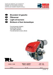
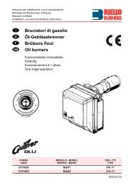
Istruzioni per installazione, uso e manutenzioneMontage und Be<strong>di</strong>enungs AnleitungManuel d’entretienInstallation, use and maintenance instructionsIDFGB<strong>Bruciatori</strong> <strong>di</strong> <strong>gasolio</strong><strong>Öl</strong>-<strong>Gebläsebrenner</strong><strong>Brûleurs</strong> <strong>fioul</strong><strong>Oil</strong> <strong>burners</strong>Funzionamento monosta<strong>di</strong>oEinstufigFonctionnement à 1 allureOne stage operationCODICECODEMODELLO - MODELLMODELE - MODELTIPO - TYPTYPE3738850 BG5 388 T13738851 BG5E Con/mit/avec/with FLAME MONITOR 388 T12902320 (0)
INDEX1. BESCHREIBUNG DES BRENNERS . . . . 11.1 Mitgeliefertes Zubehör . . . . . . . . . . . . . . . 12. TECHNISCHE MERKMALE. . . . . . . . . . . 22.1 Technische Daten. . . . . . . . . . . . . . . . . . . 22.2 Abmessungen . . . . . . . . . . . . . . . . . . . . . 22.3 Betriebsbereich . . . . . . . . . . . . . . . . . . . . 23. INSTALLATION . . . . . . . . . . . . . . . . . . . . 33.1 Brennermontage . . . . . . . . . . . . . . . . . . . 33.2 Brennstoffversorgung. . . . . . . . . . . . . . . . 33.3 <strong>Öl</strong>versorgungsanlage . . . . . . . . . . . . . . . . 43.4 Elektrisches Verdrahtungsschema . . . . . . 54. BETRIEB . . . . . . . . . . . . . . . . . . . . . . . . . 64.1 Einstellung der Brennerleistung . . . . . . . . 64.2 Pumpendruck und Luftdurchsatz. . . . . . . . 74.3 Elektrodeneinstellung . . . . . . . . . . . . . . . . 84.4 Einstellung des Flammendetektors . . . . . . 84.5 Vorwärmung des Heizöl-EL. . . . . . . . . . . . 94.6 Betriebsablauf. . . . . . . . . . . . . . . . . . . . . . 95. WARTUNG . . . . . . . . . . . . . . . . . . . . . . . . 96. AUSFÜHRUNG MIT “FLAME MONITOR” 107. STÖRUNGEN / ABHILFE . . . . . . . . . . . . .111. BESCHREIBUNG DES BRENNERSEinstufiger <strong>Öl</strong>brenner mit blauer Flamme und niedrigem Schadstoffausstoß (Stickoxyde NOx, KohlenmonoxydCO und unverbrannte Kohlenwasserstoffe CmHn).Der Brenner ist ausgerüstet mit einer thermischen Luftregulierung, <strong>di</strong>e mit der Lufteinstellklappe auf <strong>di</strong>eRegulierung des Luftdurchsatzes einwirkt. Diese thermische Luftregulierung ermöglicht einen konstant hohenCO2-Wert in Abhängigkeit der Verbrennungsluft- Temperatur.Um bestmögliche Verbrennungs-Ergebnisse sowie niedrige Emissionswerte zu erzielen,muß <strong>di</strong>e Brennkammer-Geometrie des Heizkessels für den Brenner geeignet sein.Deshalb ist es notwen<strong>di</strong>g, vor Einsatz des Brenners Imformationen beiRIELLO einzuholen, um ein einwandfreies Funktionierendes Brenners zu gewährleisten.1 – <strong>Öl</strong>pumpe2 – Steuergerät3 – Entstörtaste mit Störanzeige4 – Kesselflansch mitIsolier<strong>di</strong>chtung5 – Luftklappenregulierung6 – Düsenstock7 – Flammendetektor8 – Luftsteuerung9 – Temperatur-Fühler derthermischen Luftregulierung10 – Startverzögerer■ DIN-Reg.-Nr. : 5G474/95 nach EN 267.Abb. 1■ Der Brenner entspricht der Schutzart IP 40 gemäß EN 60529.■ Brenner mit CE-Kennzeichnung gemäß der EWG-Richtlinien: EMV 89/336/EWG, Niederspannungsrichtlinie73/23/EWG, Maschinenrichtlinie 89/392/EWG und Wirkungsgradrichtlinie 92/42/EWG.1.1 MITGELIEFERTES ZUBEHÖRKesselflansch mit Isolier<strong>di</strong>chtung . . 1 St. Schraube und Muttern für Brenner-Flansch . . . . . . 1 St.<strong>Öl</strong>schläuche mit Anschlußnippel . . 2 St. Schrauben und Muttern für Kesselflansch . . . . . . . 2 St.S715523201 D
2. TECHNISCHE MERKMALE2.1 TECHNISCHE DATENDurchsatzFeuerungswärmeleistung2.2 ABMESSUNGEN4,3 ¸ 6,1 kg/h51 ¸ 72,3 kWBrennstoff Heizöl-EL (nach DIN 51603, ÖNORM C1109),max. Viskosität bei 20°C: 6 mm 2 /sStromversorgung Einphase, 230V ± 10% ~ 50HzMotor Stromaufnahme 1,8A – 2750 U/min – 289 rad/sKondensator6,3 mFZündtransformator Sekundärspannung 8 kV – 16 mAPumpeLeistungsaufnahmeDruck: 8 ¸ 15 bar0,47 kW230 307 300 18910634583ø 9745°8345°1228514011D5485341702.3 BETRIEBSBEREICH (nach EN 267)1,0Druck im Feuerraummbar0,80,60,40,204,34,555,5 6Heizöldurchsatz – kg/hD5385505560 65 70 Brennerleistung – kW23202 D
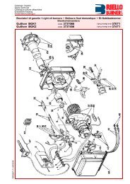
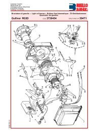
3. INSTALLATION3.1 BRENNERMONTAGEWICHTIGER HINWEISDie Kesseltür darf mit Isolierunghöchstens 100 mm <strong>di</strong>ck sein.D5012Abb. 2Abb. 4Abb. 3S7144Abb. 5D5025■ Die Schraube und <strong>di</strong>e beiden Muttern am Flansch (1) montieren (siehe Abb. 3).■ Falls erforderlich, <strong>di</strong>e Bohrungen der Isolier<strong>di</strong>chtung (5) erweitern (siehe Abb. 4).■ Mit den Schrauben (2) und (falls erforderlich) den Muttern (3) den Flansch (1) an der Kesseltür (4) mitIsolier<strong>di</strong>chtung (5) montieren (siehe Abb. 2).■ Nach Abschluß der Montagearbeiten überprüfen, ob der Brenner leicht geneigt ist, wie in Abb. 5.3.2 BRENNSTOFFVERSORGUNGAbb. 6121D5530Die <strong>Öl</strong>schläuche werden mit den Winkelanschlüssen an der <strong>Öl</strong>pumpe montiert, wobei <strong>di</strong>e <strong>Öl</strong>schläuche nachlinks oder nach rechts aus dem Brenner herausgeführt werden können.Es muß jeweils <strong>di</strong>e Halteschelle (1) bzw. der Verschlußwinkel (2) gewechselt werden (siehe Abb. 6).23203 D
3.3 ÖLVERSORGUNGSANLAGEWICHTIGER HINWEIS:■ Es muß sichergestellt werden, daß <strong>di</strong>e <strong>Öl</strong>rücklauf-Leitung ohneVerengung und Verstopfung frei in den Tank zurückgeführtwird. Durch Druckerhöhung von mehr als 0,5 bar im Rücklaufwird <strong>di</strong>e <strong>Öl</strong>pumpe un<strong>di</strong>cht.■ Die Pumpe ist werksseitig für den Zweirohr-Betrieb eingerichtet.Wird ein Pumpen-Einrohrbetrieb für notwen<strong>di</strong>gerachtet, so ist der Zapfen (2) zu lösen und <strong>di</strong>e By-PassSchraube (3) zu entfernen. Danach ist der Zapfen wiederanzuschließen, (siehe Abb. 8).max. 4 mIN DEUTSCHLAND NICHTZULÄSSIGE ANLAGED5488H*Abb. 7HMeter0,511,52ø i8 mm10204060L Meterø i10 mm204080100AUFFÜLLEN DER PUMPE MIT HEIZÖL:Bei der in Abb. 7 dargestellten Anlageist es ausreichend, wenn man den Vakuummeteranschluß(6, Abb. 8) lockert und das Austreten des Brennstoffes abwartet.Bei den in Abb. 9 und in Abb. 10 dargestellten Anlagen den Brenner starten unddas Auffüllen abwarten. Sollte vor Eintritt des Brennstoffes eine Störabschaltungerfolgen, mindestens 20 Sekunden warten und danach den Vorgang wiederholen.Der max. Unterdruck in der Saugleitung von 0,4 bar (30 cm Hg) darf nicht unterschrittenwerden. Unter <strong>di</strong>esem Wert bilden sich im Brennstoff Gase. Sichunbe<strong>di</strong>ngt vergewissern, daß <strong>di</strong>e Leitungen absolut <strong>di</strong>cht sind.Bei den Anlagen nach Abb. 10, empfehlen wir, <strong>di</strong>e <strong>Öl</strong>rücklauf-Leitung in gleicherHöhe wie <strong>di</strong>e Saugleitung im Tank enden zu lassen. Es kann auf ein Fußventil inder Saugleitung verzichtet werden. Endet <strong>di</strong>e Rücklauf-Leitung über dem<strong>Öl</strong>niveau wird auf der Saugseite zwingend ein Fußventil benötigt, wobei <strong>di</strong>esesdann bei Verschmutzung Probleme verursachen kann.H*max. 4 mHD55271 – Saugleitung2 – Rücklaufleitung3 – By-pass schraube4 – Manometeranschluß5 – Druckregler6 – Vakuummeteranschluß7 – <strong>Öl</strong>magnetventilAbb. 9 Abb. 10*1Abb. 8max. 4 mHMeter00,511,5233,5ø i8 mm353025201586L Meterø i10 mm10010010090703020765HH432D5489In der Brennstoff–Ansaugleitung muß ein Filter eingebaut werden.NUR FÜR ITALIEN: automatische Absperrung gemäß Rundschreiben des Innenministeriums Nr. 73 vom 29.7.71.*H = Höhenunterschied; L = max. Länge der Saugleitung; ø i = Innendurchmesser der Leitung.23204 D
3.4 ELEKTRISCHES VERDRAHTUNGSSCHEMA230V ~ 50HzLNSchalter mitSicherungWICHTIGER HINWEIS NULLEITER NICHTMIT DER PHASE VERWECHSELN*(Siehe Seite 4). Die automatische Absperrung(230V - 0,5A max.) an den N – T2 Klemmendes 7– poliges Steckers anschliessen.6A max.hBetriebsstundenzähler(230V - 0,1A max.)Sicherheits-Temperatur-BegrenzerTNulleiterRegelthermostatTExterne Störlampe(230V - 0,1A max.)7–poliger SteckerL1NT1T2S3B47–polige SteckdoseWERKSSEITIGE EINSTELLUNGZündelektrodenSTEUERGERÄT550SEM1 2 31 21 2 31 2 3 4SchwarzBlauBraunSchwarzWeißBlauFlammendetektorMotorM<strong>Öl</strong>ventilKondensatorSchwarzBraunS7145Vorwärmer mitStartfreigabethermostatBlauD5521Brenner-ErdungANMERKUNGEN:– Leiterdurchmesser 1 mm 2 .– Die vom Installateur ausgeführten elektrischen Verbindungen müssen denLokalen Bestimmungen entsprechen.– Um das Steuergerät vom Brenner abnehmen zu können, müssen <strong>di</strong>eSteckverbindungen zu allen Komponenten, der 7– polige Steckersowie das Erdungskabel und dann <strong>di</strong>e Schraube (A, Abb. 11) gelöstwerden.Falls das Steuergerät ausgebaut wird, <strong>di</strong>e Schraube (A) mit einemAnziehmoment von 1 ¸ 1,2 Nm wieder anschrauben.PRÜFUNG:Die Regelabschaltung des Brenners kann man überprüfen, indem man<strong>di</strong>e Thermostate öffnet. Die Störabschaltung kann man überprüfen,indem man den Flammendetektor verdunkelt.Abb. 11S705023205 D
4. BETRIEB4.1 EINSTELLUNG DER BRENNERLEISTUNGIn Konformität mit der Wirkungsgradrichtlinie 92/42/EWG müssen <strong>di</strong>e Anbringung des Brenners am Heizkessel,<strong>di</strong>e Einstellung und <strong>di</strong>e Inbetriebnahme unter Beachtung der Betriebsanleitung der Heizkessels ausgeführtwerden, einschließlich Kontrolle der Konzentration von CO und CO 2 in den Abgasen, ihrer Temperatur und dermittlenen Kesseltemperatur.Entsprechend der gewünschten Kesselleistung werden Düse, Pumpendruck und Luftklappeneinstellung gemäßfolgender Tabelle bestimmt. Die in der Tabelle aufgeführten Werte betreffend <strong>di</strong>e grosse Flamme gelten bei12,5% CO2 auf Meereshöhe und bei Null-Druck im Feuerraum.1DüsePumpen-DruckBrenner-DurchsatzLuftklappeneinstellungKleineFlammeGrosseFlammeGPH Winkel bar kg/h ± 4% Raste Raste1,10 80° 13 4,3 0,3 3,11,25 80° 14 5,1 0,6 3,91,35 80° 14 5,5 0,7 4,71,50 80° 14,5 6,2 0,9 6,0In dem Durchsatzbereich von 4,3 bis6,1 kg/h und unter Verwendung deruntengenannten Düsen (mit FilterDelavan DROPSTOP Typ 60030)wurden Verbrennungswerte nachder Grundlage RAL-UZ 9, AusgabeMärz 1997, erreicht:Typ :2Delavan 1,10 GPH - 80° WDelavan 1,35 GPH - 80° WDelavan 1,50 GPH - 80° W1DÜSEN ZU VERWENDEN:Delavan 80° W mit Filter DROPSTOP Typ60030.ZUR MONTAGE DER DÜSE WIE FOLGT VOR-GEHEN, (siehe Abb. 12):– Den Düsenstock (1) herausnehmen, nachdemvorher <strong>di</strong>e Schrauben (3) gelockert, <strong>di</strong>e Mutter(5) gelöst, <strong>di</strong>e Zündkabel (7) vom Steuergerät,<strong>di</strong>e Steckdose (6) und den Flammendetektor(4) abgenommen wurden.– Die Zündkabel (7) von den Elektroden abnehmen,den Stauscheibenhalter (8) vom Düsenstock(1) herausnehmen, nachdem <strong>di</strong>eSchraube (3, Abb. 15, Seite 8) gelockert wurde.– Die Düse (9) richtig anschrauben, wie abgebildet.71ACHTUNG– Bei der Wiedermontage des Düsenstockes<strong>di</strong>e Mutter (5) anschrauben wie in Abb. 13dargestellt.– Um eine hermetische Dichtheit der Stauscheibein ihrem Sitz zu gewahrleisten, überprüfendass mindestens 1 mm Federung zwischenDüsenstock und Gehäuse existiert.Demzufolge muss der Sperrbolzen (Splint) (2)mindestens 1 mm von der Flansch des Düsenstockesvorstrecken.6 5 4Abb. 12382ANZIEHEN, OHNEBIS ZUM ANSCHLAGAUSZUFAHREN59S7160Abb. 13D568423206 D
4.2 PUMPENDRUCK UND LUFTDURCHSATZDer Brenner ist, um auf jedem beliebigen Kessel einen gleichmässigen Anlauf zu gewährleisten, mit einer vomSteuergerät unabhängigen hydraulischen Vorrichtung versehen, welche den Durchsatz des Brennstoffes undder Luft verringert.Während der Zündung beträgt der Druck an der Düse 12 bar. Nach 3 - 9 Sekunden geht er automatisch auf14 bar über.Der Luftdurchsatz, ursprünglich auf <strong>di</strong>e kleine Flamme abgestimmt, gleicht sich bei Veränderung des Druckes,automatisch dem Bedarf der großen Flamme an.■ EINSTELLUNG DER TEILLAST (Siehe Abb. 14)LUFTKLAPPENEINSTELLUNGDie Schraube (8) um etwa eine Umdrehung lösen; in <strong>di</strong>eser Weise bleibt der Brenner andauernd auf Teillast.Die Kontermutter (5) lösen und durch Drehen der Schraube (4) den Zeiger (6) auf <strong>di</strong>e gewünschte Stellungbringen. Dann <strong>di</strong>e Kontermutter (5) wieder festdrehen und <strong>di</strong>e Schraube (8) festdrehen.ACHTUNG:– Die in der Tabelle angegebene Werteder Rasten sind nur zeigend.– Die Einstellung soll bei CO2 nicht niedrigerals 13% ausgeführt worden.Abb. 14STARTVERZÖGERER-EINSTELLUNG:Wird serienmäßig auf 12 bar eingestellt.Es empfiehlt sich, <strong>di</strong>esen Wert nicht zukürzen.Der Manometer zur Druckkontrolle wird anstattdes Verschlusses (4, Abb. 8, Seite 4) montiert.Muß der Druck neu eingestellt werden oderwünscht man ihn zu ändern, so braucht mannur <strong>di</strong>e Schraube (7)verändern nachdem man <strong>di</strong>e Schraube (8) gelösthat.■ EINSTELLUNG DER VOLLAST(Siehe Abb. 14)LUFTKLAPPENEINSTELLUNGDie Kontermutter (3) lösen und durch Drehender Schraube (1) <strong>di</strong>e Anzeige (2) auf <strong>di</strong>e gewünschteStellung einstellen. Dann <strong>di</strong>e Kontermutter(3) wieder festdrehen.S7161PUMPENEINSTELLUNG:Wird serienmäßig auf 14 bar eingestellt.Der Manometer zur Druckkontrolle wird anstatt des Verschlusses (4, Abb. 8, Seite 4) montiert.Muß der Druck neu eingestellt werden oder wünscht man ihn zu ändern, so braucht man nur <strong>di</strong>e Schraube(5, Abb. 8, Seite 4) zu drehen.Bei Brennerstillstand schließt <strong>di</strong>e Luftklappe automatisch, bis zu einem max. Unterdruck im Schornsteinvon 0,5 mbar.23207 D
2BEMERKUNG (RAL-UZ 9 DEUTSCHLAND)– Ein Betriebsstundenzähler zur Ermittlung des Jahresnutzungsgrades und zur Abstimmung des Heizkesselsauf den Wärmebedarf wird empfohlen.– Ein Abgasthermometer, das Hinweise auf <strong>di</strong>e Verschmutzung der Heizflächen und auf eine falsche Brennereinstellunggeben kann, wird empfohlen.➤Voraussetzung für <strong>di</strong>e einwandfreie Funktion der Feuerungsanlage ist der richtig <strong>di</strong>mensionierte Schornstein.Die Dimensionierung erfolgt nach DIN 4705 auf Basis der Abgaswerte aus der techn. Datentabelle.➤Der Brenner darf nur an einem Heizkessel verwendet werden, wenn <strong>di</strong>e Wärmeleistung des Heizkesselsden Leistungsbereich des <strong>Öl</strong>brenners nicht überschreitet und der Druck im Feuerraum <strong>di</strong>e im Arbeitsfelddes Brenners festgelegten Grenzwerte nicht überschritten werden.4.3 ELEKTRODENEINSTELLUNGWICHTIGER HINWEISDie Isolatoren der Zündelektroden(1) an der Scheibe (2) biszum Anschlag bringen.(Siehe Abb. 15).Um Zugang zu den Elektroden zuerhalten, <strong>di</strong>e im Kapitel 4.1 unterdem Stichpunkt “DÜSEN ZU VER-WENDEN” (S. 6) beschriebene Anleitungbefolgen.Abb. 15WICHTIGER HINWEIS Die Abstände und <strong>di</strong>eStellung nach oben müssen06,5 + 0,5 mm eingehalten werden.213D57578 mm4.4 EINSTELLUNGDES FLAMMENDETEKTORS (Siehe Abb. 16)Die Empfindlichkeit des Flammendetektors kann mit dem Potentiometer(3) reguliert werden. Werksseitig ist er auf Stellung 4eingestellt.Die LED-Anzeige (1) zeigt <strong>di</strong>e optimale Empfindlichkeit.Die LED-Anzeige (2) zeigt den Betrieb.Abb. 16■ Während der Vorbelüftung leuchtet keine LED-Anzeige.■ Die optimale Empfindlichkeit wird durch Aufleuchten beiderLED-Anzeigen signalisiert.➤ Wenn <strong>di</strong>e LED-Anzeige (1) flackert, das Potentiometer im Uhrzeigersinndrehen, bis sie stän<strong>di</strong>g aufleuchtet, dann den Zeigergegen den Uhrzeigersinn drehen, bis <strong>di</strong>e LED flackert.Danach <strong>di</strong>e Empfindlichkeit durch Verstellen des Potentiometersum eine oder zwei Kerben im Uhrzeigersinn erhöhen.➤ Nach mindestens 5 Minuten Stillstand prüfen, ob <strong>di</strong>e so ausgeführteEinstellung ein korrektes Anfahren des Brennerserlaubt.S712932123208 D
4.5 VORWÄRMUNG DES HEIZÖL–ELUm auch bei niedrigen Heizöl–Temperaturen eine ordnungsgemäße Zündung zu ermöglichen, ist der Brennermit einer <strong>Öl</strong>vorwärmung ausgestattet.Ein Thermostat in der <strong>Öl</strong>vorwärmung gibt den Brenner erst bei einer Heizöltemperatur von 70°C frei und einzusätzlich eingebauter PTC–Widerstand sorgt für eine gleichbleibende <strong>Öl</strong>temperatur.Die Vorwärmung bleibt während des Betriebs eingeschaltet und schaltet sich bei Brennerstillstand aus.4.6 BETRIEBSABLAUFThermostatVorwärmerMotorZündtransformatorVentilKleine FlammeGrosse FlammeStörlampeStörabschaltungwegen nicht erfolgterZündungNormal0¸150s3¸9sStörabschaltung wegenNichtzündung A0¸150s ~12sStörabschaltungwegen Nichtabschaltens0¸150s3¸9s20¸60sB~12s5s~12sD5531ABWird durch <strong>di</strong>e Kontrollampe am Steuer- und Überwachungsgerät signalisiert (3, Abb. 1, S. 1).In <strong>di</strong>esem Fall fährt der Brenner nicht wieder an, da eine besonders schwerwiegende Störung vorliegt.DEN KUNDENDIENST RUFENDER AUTORISIERTE KUNDENDIENST MUß ZUERST DIE FUNKTION FOLGENDER EINRICHTUNGENÜBERPRÜFEN:■ Flammendetektor (7, Abb. 1, S. 1).■ Pumpe: <strong>Öl</strong>magnetventil (7) oder Kolben des Druckreglers (5), siehe Abb. 8, S. 4.DIE STÖRABSCHALTUNG KANN MIT HILFE EINES ENTSPRECHENDEN WERKZEUGS DURCH DIE AMBODEN DES STEUERGERÄTES BEFINDLICHE AUSSPARUNG BESEITIGT WERDEN.5. WARTUNGDer Brenner muß in regelmäßigen Zeitabständen vom Kunden<strong>di</strong>enst gewartet werden.Die Wartung ist für den umweltfreundlichen Betrieb des Brenners unbe<strong>di</strong>ngt notwen<strong>di</strong>g. Es wird dadurchsichergestellt, daß bestmögliche Energie-Verbrauchswerte erreicht werden, was mit einer Schadstoff-Reduzierunggleichzusetzten ist. Vor jeder Wartungsarbeit den Brenner stromlos schalten.WICHTIGSTE WARTUNGSARBEITEN:■ Überprüfen, ob <strong>di</strong>e <strong>Öl</strong>versorgungsleitung und <strong>di</strong>e Rücklaufleitung weder verstopft noch geknickt sind.■ Filter in der Versorgungsleitung und an der Pumpe reinigen.■ Korrekten Brennstoffverbrauch überprüfen.■ <strong>Öl</strong>düse austauschen.■ Brennkopf und Stauscheibe reinigen.■ Brenner ca. 10 Minuten auf voller Leistung laufen lassen, alle in <strong>di</strong>esem Handbuch aufgeführten Elementekorrekt einstellen. Danach Abgasanalyse erstellen:● Abgastemperatur; ● CO 2 - Gehalt (%); ● CO-Gehalt (ppm); ● Rußtest.23209 D
6. AUSFÜHRUNG MIT “FLAME MONITOR”KONTROLLMÖGLICHKEITEN DURCH DEN “FLAME MONITOR”:■ Leucht<strong>di</strong>ode “L1 bis L5” signalisieren den Betriebszustand des Brenners.■ Die Leucht<strong>di</strong>oden “L6 bis L15” signalisieren <strong>di</strong>e Flammenqualität.BETRIEBSWEISEDie Signale für den Betriebszustand des Brenners kommenvom Feuerungsautomaten Typ 550SE über einen neunpoligenAnschlußstecker (C). Das Signal für <strong>di</strong>eFlammenüberwachung kommt von einemzusätzlichen Fotowiderstand (D).S7053L1 BETRIEBSBEREITSCHAFTDiese Leucht<strong>di</strong>ode zeigt an, daß der Brennerbetriebsbereit ist.S7162L2 VORWÄRMUNGDiese Leucht<strong>di</strong>ode signalisiert <strong>di</strong>e Vorwärmphase nach Anforderung über<strong>di</strong>e Kesselregelung. Nach Erreichen der optimalen Vorwärmtemperaturschaltet <strong>di</strong>ese Leucht<strong>di</strong>ode ab.L3 VORBELÜFTUNGDiese Leucht<strong>di</strong>ode brennt nur während der Vorbelüftungsphase.L4 STÖRABSCHALTUNG WEGEN NICHTZÜNDUNGDiese Leucht<strong>di</strong>ode brennt, wenn eine Störabschaltung wegen mangelnderFlammenbildung ausgelöst wurde. Diese Störabschaltung kann vomBetreiber mit der Entstörtaste am Steuergerät beseitigt werden.S7147L5 STÖRABSCHALTUNG WEGEN NICHTABSCHALTENSDiese Leucht<strong>di</strong>ode brennt, wenn Funktionsstörungen im Bereich des <strong>Öl</strong>magnetventils bzw. der Fotozelle für<strong>di</strong>e Flammenüberwachung vorliegen.Da in <strong>di</strong>esem Fall eine Funktionsstörung am Brenner vorliegt, kann <strong>di</strong>ese Störabschaltung erst nach Beseitigungdes Fehlers durch den Servicemonteur aufgehoben werden (Abs. 4.6 und 7 sehen).L6 . . . L15 FLAMMENQUALITÄTEine blaue Flamme signalisiert eine gute, d.h. emissionsarme Verbrennung. Dieser Betriebszustand wirddurch eine Abgasanalyse überprüft und auf beste CO2- Werte sowie Abgastemperatur eingestellt.Nach ca. 5 Minuten Brennerbetrieb sollten 1 - 2 grüne Leucht<strong>di</strong>oden brenner (kann auf der Rückseite des“Flame Monitor” an Pos. (E) mit einem Schraubendreher 2 mm nachjustiert werden).Wenn nach längerer Betriebszeit gelbe oder sogar rote Leucht<strong>di</strong>oden brennen, ist eine Reinigung und Überprüfungdes Brenner durch einen Fachmann erforderlich.ACHTUNG:Um <strong>di</strong>e Brennerhaube (B) abnehmen zu können, müssen <strong>di</strong>e Schrauben (A) gelöst werden.Ist ein Flammenmonitor vorhandern, <strong>di</strong>e Haube bis an <strong>di</strong>e hinterste Kante des Steuergerätesabziehen und dann den Stecker (C) sowie den Fotowiderstand (D) abziehen.232010 D
7. STÖRUNGEN / ABHILFENachfolgend finden Sie einige denkbare Ursachen und Abhilfemöglichkeiten für Störungen, <strong>di</strong>e den Betriebdes Brenners beeinflussen oder einen nicht ordnungsgemäßen Betrieb des Brenners verursachen könnten.In den meisten Fällen führt eine Störung zum Aufleuchten der Kontrolleuchte in der Entstörtaste des Steuergeräts(Pos. 3, Abb. 1, S. 1).Beim Aufleuchten <strong>di</strong>eses Signals kann der Brenner erst nach Drücken der Entstörtaste wieder in Betriebgesetzt werden. Wenn anschließend eine normale Zündung erfolgt, so war <strong>di</strong>e Störabschaltung auf einevorübergehende, ungefährliche Störung zurückzuführen.Wenn hingegen <strong>di</strong>e Störabschaltung weiterhin fortbesteht, so sind <strong>di</strong>e Ursachen der Störung und <strong>di</strong>e entsprechendenAbhilfemaßnahmen folgender Tabelle zu entnehmen:STÖRUNGEN MÖGLICHE URSACHE ABHILFEBei Wärmeanforderungläuft der Brenner nichtan.Keine Stromzufuhr.Vorwärmung oderFreigabethermostate defekt.Die Verbindungen des Steuergerätessind nicht richtig eingesteckt.Es ist eine Störabschaltung wegenfehlender Abschaltung erfolgt.(Ereignis B, S. 9).Spannung zwischen den Klemmen L1 - Ndes 7- poligen Steckers prüfen.Sicherungen überprüfen.Überprüfen, ob der max.- Thermostatnicht auf Störabschaltung steht.Austauschen.Sämtliche Steckverbindungen überprüfenund bis zum Anschlag einstecken.Kunden<strong>di</strong>enst rufen.Der Brenner bleibt inder Vorbelüftungsphase.Der Brenner führt denVorbelüftungs-und Zündzyklusregulär aus; nachungefähr 5 Sekunden erfolgteine Störabschaltung.Gelbe FlammeAnfahren des Brennersmit verspäteterZündung.WICHTIGER HINWEIS:Der Flammendetektor meldet Fremdlicht(LED-Anzeige 1 aufleuchtet).Der Flammendetektor ist verschmutzt.Der Flammendetektor ist defekt.Die Flamme reißt ab oder bildetsichnicht.Verschmutzte oder defekte Düse.Luftdurchsatz fehlerhaft.Pumpendruck nicht korrekt eingestellt.Luftzufuhröffnung verschmutzt.Kessel verschmutzt.Zündelektroden nicht in richtigerPosition.Zu hoher Luftdurchsatz.Verschmutzte oder defekte Düse.Lichtquelle beseitigen.Reinigen.Austauschen.Brennstoffdruck und- Durchsatzüberprüfen.Luftdurchsatz überprüfen.Düse wechseln.Magnetventilspule überprüfen.Austauschen.Luftdurchsatz nachregulieren.Brennstoffdruck und -Durchsatz überprüfenund gemäß den Angaben <strong>di</strong>eser Anleitungeinstellen.ReinigenReinigenGemäß den Angaben <strong>di</strong>eser Anleitungkorrekt einstellen.Gemäß den Angaben <strong>di</strong>eser Anleitungden Luftdurchsatz korrekt einstellen.Austauschen.Jegliche vertragliche und außervertragliche Haftung des Herstellers für Schäden an Personen, Tieren undSachen, <strong>di</strong>e durch Fehler bei der Installation und Einstellung des Brenners, durch unsachgemäßen, falschenund unvernünftigen Gebrauch desselben, durch Nichtbeachtung der mitgelieferten Be<strong>di</strong>enungsanleitungund durch das Eingreifen von unbefugtem Personal verursacht werden, ist ausgeschlossen.232011 D
Dichiarazione del produttore secondo la normativa 1. BImSchV, 1996R.B.L. RIELLO BRUCIATORI LEGNAGO S.p.A. <strong>di</strong>chiara che i seguenti prodotti rispettano ivalori limite degli NOx imposti dalla normativa 1. BImSchV, 1996, § 7 (2):Herstellerbescheinigung gemäß 1. BImSchV, 1996R.B.L. RIELLO BRUCIATORI LEGNAGO S.p.A. bestätigt, daß folgende Produkte, <strong>di</strong>e vonder 1. BImSchV, 1996, § 7 (2) geforderten NOx - Grenzwerte einhalten:Déclaration du producteur selon la <strong>di</strong>rective 1. BImSchV, 1996R.B.L. RIELLO BRUCIATORI LEGNAGO S.p.A. déclare que les brûleurs suivants respectentles valeurs limites de NOx imposées par la <strong>di</strong>rective 1. BImSchV, 1996, § 7 (2):Producer declaration accor<strong>di</strong>ng to 1. BImSchV, 1996R.B.L. RIELLO BRUCIATORI LEGNAGO S.p.A. declares, that the following products complywith the NOx limit values in<strong>di</strong>cated in the 1. BImSchV. 1996 § 7 (2) standard:Prodotto - ProduktreiheProduit - Product<strong>Bruciatori</strong> <strong>di</strong> <strong>gasolio</strong><strong>Öl</strong>-<strong>Gebläsebrenner</strong><strong>Brûleurs</strong> <strong>fioul</strong><strong>Oil</strong> <strong>burners</strong>Tipo -Typ - Type388 T1388 T1Modello - AusführungModèle - ModelBG5BG5ER.B.L. RIELLO BRUCIATORI LEGNAGO S.p.A.2320
INDICE1. DESCRIZIONE DEL BRUCIATORE . . . . . 11.1 Materiale a corredo . . . . . . . . . . . . . . . . . 12. DATI TECNICI . . . . . . . . . . . . . . . . . . . . . 22.1 Dati tecnici . . . . . . . . . . . . . . . . . . . . . . . . 22.2 Dimensioni . . . . . . . . . . . . . . . . . . . . . . . . 22.3 Campo <strong>di</strong> lavoro . . . . . . . . . . . . . . . . . . . . 23. INSTALLAZIONE. . . . . . . . . . . . . . . . . . . 33.1 Fissaggio alla caldaia. . . . . . . . . . . . . . . . 33.2 Alimentazione del combustibile . . . . . . . . 33.3 Impianti idraulici . . . . . . . . . . . . . . . . . . . . 43.4 Collegamenti elettrici . . . . . . . . . . . . . . . . 54. FUNZIONAMENTO. . . . . . . . . . . . . . . . . . 64.1 Regolazione della combustione. . . . . . . . . 64.2 Pressione pompa e portata aria . . . . . . . . 74.3 Regolazione elettro<strong>di</strong> . . . . . . . . . . . . . . . . 84.4 Regolazione rivelatore fiamma . . . . . . . . . 84.5 Riscaldamento del combustibile . . . . . . . . 94.6 Programma <strong>di</strong> avviamento . . . . . . . . . . . . 95. MANUTENZIONE . . . . . . . . . . . . . . . . . . . 96. VERSIONE CON “FLAME MONITOR” . . . 107. ANOMALIE / RIMEDI . . . . . . . . . . . . . . . .118. NORME GENERALI DI SICUREZZA . . . . 121. DESCRIZIONE DEL BRUCIATOREBruciatore <strong>di</strong> <strong>gasolio</strong> con funzionamento monosta<strong>di</strong>o, a fiamma blu, e quin<strong>di</strong> con basse emissioni inquinanti(Ossi<strong>di</strong> d’Azoto NOx, Ossido <strong>di</strong> carbonio CO e Idrocarburi incombusti).Il bruciatore è inoltre dotato <strong>di</strong> un <strong>di</strong>spositivo (compensatore), solidale alla serranda <strong>di</strong> regolazione della portatad’aria, che mantiene costante il livello <strong>di</strong> ossigeno necessario alla combustione e in<strong>di</strong>pendentemente dalvariare della temperatura ambiente.Al fine <strong>di</strong> garantire una combustione col minimo tasso <strong>di</strong> emissioni inquinanti,le <strong>di</strong>mensioni ed il tipo <strong>di</strong> camera <strong>di</strong> combustione del generatore<strong>di</strong> calore, devono corrispondere a valori ben definiti. È pertantoconsigliato consultare il Servizio Tecnico RIELLO prima <strong>di</strong>scegliere questo tipo <strong>di</strong> bruciatore per l’abbinamentocon una caldaia.1 – Pompa olio2 – Apparecchiatura <strong>di</strong>comando e controllo3 – Pulsante <strong>di</strong> sblocco consegnalazione <strong>di</strong> blocco4 – Flangia con schermoisolante5 – Gruppo regolazioneserranda aria6 – Gruppo portaugello7 – Rivelatore fiamma8 – Martinetto9 – Sensore <strong>di</strong> temperaturadel compensatore10 – RitardatoreFig. 1■ Approvazione DIN n° : 5G474/95 secondo EN 267.■ Il bruciatore risponde al grado <strong>di</strong> protezione IP 40 secondo EN 60529.■ Bruciatore con marcatura CE in conformità alle Direttive CEE: CEM 89/336/CEE, Bassa Tensione 73/23/CEE,Macchine 89/392/CEE e Ren<strong>di</strong>mento 92/42/CEE.1.1 MATERIALE A CORREDOFlangia con schermo isolante. . . . N° 1 Viti e da<strong>di</strong> per flangia <strong>di</strong> fissaggio alla caldaia . . . . N° 2Vite e da<strong>di</strong> per flangia . . . . . . . . . N° 1 Tubi flessibili con nipples . . . . . . . . . . . . . . . . . . . . N° 2S715523201 I
2. DATI TECNICI2.1 DATI TECNICIPortata4,3 ¸ 6,1 kg/hPotenza termica51 ¸ 72,3 kWCombustibileGasolio, viscosità max. a 20°C: 6 mm2/sAlimentazione elettrica Monofase, 230V ± 10% ~ 50HzMotore 1,8 A assorbiti – 2750 g/min – 289 rad/sCondensatore6,3 mFTrasformatore d’accensione Secondario 8 kV – 16 mAPompa Pressione: 8 ¸ 15 barPotenza elettrica assorbita0,47 kW2.2 DIMENSIONI230 307 300 18910634583ø 9745°8345°1228514011D5485341702.3 CAMPO DI LAVORO (secondo EN 267)Pressione in camera <strong>di</strong>combustione – mbar1,00,80,60,40,204,34,555,5 6Portata <strong>di</strong> <strong>gasolio</strong> – kg/hD5385505560 65 70 Potenza termica – kW23202 I
3. INSTALLAZIONE3.1 FISSAGGIO ALLA CALDAIAATTENZIONELa portina della caldaia deve avere uno spessoremax. <strong>di</strong> 100 mm. Rivestimento refrattario compreso.Fig. 2D5012Fig. 4Fig. 3S7144Fig. 5D5025■ Inserire sulla flangia (1) la vite e i due da<strong>di</strong> (ve<strong>di</strong> fig. 3).■ Allargare, se necessario, i fori dello schermo isolante (5) (ve<strong>di</strong> fig. 4).■ Fissare alla portina della caldaia (4) la flangia (1) me<strong>di</strong>ante le viti (2) e (se necessario) i da<strong>di</strong> (3) interponendolo schermo isolante (5) (ve<strong>di</strong> fig. 2).■ Ad installazione avvenuta verificare che il bruciatore sia leggermente inclinato come in fig. 5.3.2 ALIMENTAZIONE DEL COMBUSTIBILEFig. 6121D5530Il bruciatore è pre<strong>di</strong>sposto per ricevere i tubi <strong>di</strong> alimentazione del <strong>gasolio</strong> da entrambi i lati.A seconda che l’uscita dei tubi avvenga a destra o a sinistra del bruciatore si dovranno invertire sia lapiastrina <strong>di</strong> fissaggio (1) che la squadretta <strong>di</strong> chiusura (2) (ve<strong>di</strong> fig. 6).23203 I
3.3 IMPIANTI IDRAULICIATTENZIONE:■ Accertarsi, prima <strong>di</strong> mettere in funzione il bruciatore, che iltubo <strong>di</strong> ritorno del combustibile non abbia occlusioni. Unaeccessiva contropressione provocherebbe la rotturadell’organo <strong>di</strong> tenuta della pompa.■ La pompa è pre<strong>di</strong>sposta per funzionamento bitubo.Per il funzionamento monotubo è necessario svitare il perno(2), togliere la vite <strong>di</strong> by-pass (3) e quin<strong>di</strong> riavvitare il perno(2) (ve<strong>di</strong> fig. 8).7654max. 4 mIMPIANTO NON AMMESSOIN GERMANIAD5488H*Fig. 7HMetri0,511,52ø i8 mm10204060L Metriø i10 mm204080100INNESCO POMPANell’impianto <strong>di</strong> fig. 7 è sufficiente allentare l’attacco delvacuometro (6, fig. 8) ed attendere la fuoriuscita del combustibile.Negli impianti <strong>di</strong> fig. 9 e 10 avviare il bruciatore ed attendere l’innesco.Se avviene il blocco prima dell’arrivo del combustibile, attendere almeno20 secon<strong>di</strong>, poi ripetere l’operazione.Non si deve superare la depressione max. <strong>di</strong> 0,4 bar (30 cm Hg).Oltre tale valore si ha liberazione <strong>di</strong> gas dal combustibile. Si raccomanda che letubazioni siano a perfetta tenuta.Negli impianti in depressione si consiglia <strong>di</strong> far arrivare la tubazione <strong>di</strong> ritorno allastessa altezza della tubazione <strong>di</strong> aspirazione. In questo caso non è necessaria lavalvola <strong>di</strong> fondo. Se invece la tubazione <strong>di</strong> ritorno arriva sopra il livello del combustibilela valvola <strong>di</strong> fondo è in<strong>di</strong>spensabile. Questa soluzione è meno sicura dellaprecedente per la possibile mancanza <strong>di</strong> tenuta della valvola.D55271Fig. 81 - Aspirazione2 - Ritorno3 - Vite <strong>di</strong> by-pass4 - Attacco manometro5 - Regolatore <strong>di</strong> pressione6 - Attacco vacuometro7 - ValvolaHmetri00,511,5233,5ø i8 mm353025201586L metri32ø i10 mm10010010090703020H*max. 4 mFig. 9 Fig. 10HH*Hmax. 4 mD5489È necessario installare un filtro sulla linea <strong>di</strong> alimentazione del combustibile.SOLO PER L’ITALIA: Dispositivo automatico <strong>di</strong> intercettazione secondo circolare Ministero dell’interno n° 73 del 29/7/71.* H = <strong>di</strong>slivello; L = max. lunghezza del tubo <strong>di</strong> aspirazione; ø i = <strong>di</strong>ametro interno del tubo.23204 I
3.4 COLLEGAMENTI ELETTRICI230V ~ 50HzLNInterruttorecon fusibileATTENZIONENON SCAMBIARE IL NEUTRO CON LA FASE*(Ve<strong>di</strong> pag. 4). Collegare il <strong>di</strong>spositivo automatico<strong>di</strong> intercettazione (230V - 0,5A max.) ai morsettiN - T2 della spina 7 poli.Termostato<strong>di</strong> massima Ta riarmo manualeNeutro6A max.Termostato<strong>di</strong> regolazioneThContaore(230V - 0,1A max.)Segnalazione<strong>di</strong> blocco esterna(230V - 0,1A max.)Spina 7 poliL1NT1T2S3B4ESEGUITO IN FABBRICAPresa 7 poliElettro<strong>di</strong><strong>di</strong> accensioneAPPARECCH.550SEM1 2 31 21 2 31 2 3 4NeroBluMarroneNeroBiancoBluRivelatore fiammaValvola olioMotoreMCondensatoreNeroMarroneS7145BluD5521Riscaldatore con termostato<strong>di</strong> consenso all’avviamentoTerra bruciatoreNOTE:– Sezione dei conduttori 1,5 mm2.– I collegamenti elettrici eseguiti dall’installatore devono rispettare lenorme vigenti nel paese.– Per togliere l’apparecchiatura dal bruciatore allentare la vite(A, fig. 11) dopo aver sconnesso tutti i componenti, la spina a7 poli ed il filo <strong>di</strong> terra.In caso <strong>di</strong> smontaggio dell’ apparecchiatura riavvitare la vite (A)con una coppia <strong>di</strong> serraggio da 1 ¸ 1,2 Nm.COLLAUDO:Verificare l’arresto del bruciatore aprendo i termostati, ed il bloccooscurando il rivelatore fiamma.Fig. 11S705023205 I
4. FUNZIONAMENTO4.1 REGOLAZIONE DELLA COMBUSTIONEIn conformità con la Direttiva Ren<strong>di</strong>mento 92/42/CEE, l’applicazione del bruciatore alla caldaia, laregolazione e il collaudo, devono essere eseguiti nell’osservanza del manuale d’istruzione della caldaiastessa, compreso il controllo della concentrazione <strong>di</strong> CO e CO 2 nei fumi, della loro temperatura e <strong>di</strong> quellame<strong>di</strong>a dell’acqua della caldaia.4A seconda della portata richiesta dalla caldaia vanno definiti: l’ugello, la pressione della pompa e la regolazionedella serranda dell’aria secondo la tabella seguente.I valori <strong>di</strong> tabella in grande fiamma sono riferiti al 12,5% <strong>di</strong> CO2, al livello del mare e con pressione zero incamera <strong>di</strong> combustione.1UgelloPressionepompaPortatabruciatoreRegolazione serrandaPiccolafiammaGrandefiammaGPH Angolo bar kg/h ± 4% Tacca Tacca1,10 80° 13 4,3 0,3 3,11,25 80° 14 5,1 0,6 3,91,35 80° 14 5,5 0,7 4,71,50 80° 14,5 6,2 0,9 6,0Nel campo <strong>di</strong> portata da 4,3 a 6,1 kg/he con l’utilizzo dei sottocitati ugelli (confiltro Delavan DROPSTOP tipo 60030),sono stati raggiunti i valori <strong>di</strong> combustionesecondo RAL-UZ 9, E<strong>di</strong>zionemarzo 1997 (marchio ambientale -GERMANIA):Tipo :2Delavan 1,10 GPH - 80° WDelavan 1,35 GPH - 80° WDelavan 1,50 GPH - 80° W1 UGELLI DA UTILIZZARE:Delavan 80° W con filtro DROPSTOP tipo60030.PER MONTARE L’UGELLO ESEGUIRE LESEGUENTI OPERAZIONI (Ve<strong>di</strong> fig. 12):– Estrarre il gruppo portaugello (1) dopo averallentato le viti (3), svitato il dado (5), sfilatoi cavetti (7) dall’apparecchiatura, la presa(6) ed il rivelatore fiamma (4).– Sfilare i cavetti (7) dagli elettro<strong>di</strong>, estrarredal gruppo portaugello (1) il gruppo supportoelica (8) dopo aver allentato la vite(3, fig. 15, pag. 8).– Avvitare l’ugello (9) correttamente stringendolocome mostrato in figura.71ATTENZIONE– Al rimontaggio del gruppo portaugello avvitareil dado (5) come mostrato in fig. 13.– Per garantire una tenuta ermetica dell’elicanella propria sede, verificare che esista almeno1 mm <strong>di</strong> molleggio tra gruppo portaugelloe carcassa.Di conseguenza il perno (copiglia) (2) <strong>di</strong> fissaggiodovrà sporgere <strong>di</strong> almeno 1 mmdalla flangia del gruppo portaugello.6 5 4Fig. 12382SERRARE SENZAPORTARE A BATTUTA59Fig. 13D5684S716023206 I
4.2 PRESSIONE POMPA E PORTATA ARIAIl bruciatore per assicurare un’avviamento regolare con qualsiasi tipo <strong>di</strong> caldaia è dotato <strong>di</strong> un <strong>di</strong>spositivoidraulico, in<strong>di</strong>pendente dall’apparecchiatura, che riduce la portata del combustibile e dell’aria.All’accensione la pressione all’ugello è <strong>di</strong> 12 bar. Dopo 3 - 9 secon<strong>di</strong> passa automaticamente a 14 bar.La portata dell’aria inizialmente tarata sulla piccola fiamma, si porta automaticamente al cambio <strong>di</strong> pressionesulla portata necessaria alla grande fiamma.■ REGOLAZIONE PICCOLA FIAMMA D’ACCENSIONE (Ve<strong>di</strong> fig. 14)REGOLAZIONE SERRANDA ARIASvitare la vite (8) <strong>di</strong> circa 1 giro, in questo modo il bruciatore rimane permanentemente in piccola fiamma.Allentare il dado (5), agire sulla vite (4) e portare l’in<strong>di</strong>ce (6) sulla posizione desiderata. Quin<strong>di</strong> bloccare ildado (5) ed avvitare la vite (8).ATTENZIONE:– I valori delle tacche riportate in tabellasono in<strong>di</strong>cativi.– Effettuare la taratura con una CO2 noninferiore al 13%.Fig. 14REGOLAZIONE RITARDATORE:Viene tarato in fabbrica a 12 bar.È consigliabile non ridurre tale valore.Il manometro per il controllo della pressione vamontato al posto del tappo (4, fig. 8, pag. 4).Se è necessario ritarare tale pressione o sesi preferisce cambiarla, basta agire sulla vite(7), sempre dopo aver svitato la vite (8).■ REGOLAZIONEGRANDE FIAMMA (Ve<strong>di</strong> fig. 14)REGOLAZIONE SERRANDA ARIAAllentare il dado (3), agire sulla vite (1) fino aportare l’in<strong>di</strong>ce (2) sulla posizione desiderata.Quin<strong>di</strong> bloccare il dado (3).S7161REGOLAZIONE POMPA:Viene tarata in fabbrica a 14 bar.Il manometro per il controllo della pressione va montato al posto del tappo (4, fig. 8, pag. 4).Se è necessario ritarare tale pressione, o se si preferisce cambiarla, basta agire sulla vite (5, fig. 8, pag. 4).All’arresto del bruciatore la serranda dell’aria si chiude automaticamente, fino ad una depressione max. alcamino <strong>di</strong> 0,5 mbar.23207 I
4.5 RISCALDAMENTO DEL COMBUSTIBILEPer garantire l’accensione ed il funzionamento regolari anche alle basse temperature, il bruciatore è dotato <strong>di</strong>un riscaldatore del <strong>gasolio</strong> nella testa <strong>di</strong> combustione. Il riscaldatore si inserisce alla chiusura dei termostati.Il consenso all’avviamento del bruciatore avviene me<strong>di</strong>ante un termostato posto sul portaugello una volta raggiuntala temperatura ottimale per l’accensione.Il riscaldamento rimane inserito durante il funzionamento e si spegne all’arresto del bruciatore.4.6 PROGRAMMA DI AVVIAMENTOTermostatoRiscaldatoreMotoreTrasf. d’accensioneValvolaPiccola fiammaGrande fiammaSpia bloccoBlocco per mancatospegnimentoNormale0¸150s3¸9sBlocco per mancataaccensione A0¸150s ~12sBlocco permancato spegnimento0¸150s3¸9sB20¸60s~12s5s~12sD5531ABSegnalato dalla spia sull’apparecchiatura <strong>di</strong> comando e controllo (3, fig. 1, pag. 1).In questo caso il bruciatore non parte più in quanto si è registrato un guasto <strong>di</strong> particolare gravità.CHIAMARE IL SERVIZIO DI ASSISTENZAIL SERVIZIO DI ASSISTENZA ABILITATO DEVE PRIMA VERIFICARE L’EFFICIENZA DI:■ Rivelatore fiamma (7, fig. 1, pag. 1).■ Pompa: valvola <strong>di</strong> intercettazione (7) o il pistoncino del regolatore <strong>di</strong> pressione (5), ve<strong>di</strong> fig. 8, pag. 4.IL BLOCCO È RIPRISTINABILE INSERENDO UN OPPORTUNO UTENSILE NEL FORO POSTO SULFONDO DELL’APPARECCHIATURA DI COMANDO E CONTROLLO.5. MANUTENZIONEIl bruciatore richiede una manutenzione perio<strong>di</strong>ca, che deve essere eseguita da personale abilitato.La manutenzione <strong>di</strong>venta essenziale per un buon funzionamento del bruciatore, evitando in questo modoconsumi eccessivi <strong>di</strong> combustibile e riducendo pertanto le emissioni inquinanti nell’ambiente.Prima <strong>di</strong> effettuare qualsiasi operazione <strong>di</strong> pulizia o controllo, togliere l’alimentazione elettrica albruciatore agendo sull’interruttore generale dell’impianto.LE OPERAZIONI BASILARI DA EFFETTUARE SONO LE SEGUENTI:■ Controllare che non ci siano eventuali occlusioni o ammaccature nei tubi <strong>di</strong> alimentazione e ritorno del combustibile.■ Effettuare la pulizia del filtro <strong>di</strong> linea <strong>di</strong> aspirazione del combustibile e del filtro della pompa.■ Rilevare il corretto consumo <strong>di</strong> combustibile.■ Cambiare ugello.■ Effettuare la pulizia della testa <strong>di</strong> combustione nella zona <strong>di</strong> uscita del combustibile, sul <strong>di</strong>sco <strong>di</strong> turbolenza.■ Lasciare funzionare il bruciatore a pieno regime per circa <strong>di</strong>eci minuti, tarando correttamente tutti gli elementiin<strong>di</strong>cati nel presente manuale. Quin<strong>di</strong> effettuare un’analisi della combustione verificando:● Temperatura dei fumi al camino; ● Contenuto della percentuale <strong>di</strong> CO2; ● Contenuto <strong>di</strong> CO (ppm);● In<strong>di</strong>ce <strong>di</strong> opacità dei fumi, secondo la scala <strong>di</strong> Bacharach.23209 I
6. VERSIONE CON “FLAME MONITOR”QUESTO DISPOSITIVO PERMETTE:■ La supervisione dello stato <strong>di</strong> funzionamento del bruciatore me<strong>di</strong>ante i leds “L1 a L5”.■ La supervisione della qualità della fiamma me<strong>di</strong>ante i leds “L6 a L15”.FUNZIONAMENTOI segnali per la supervisione dello stato <strong>di</strong> funzionamento del bruciatore,sono prelevati dall’apparecchiatura 550SE me<strong>di</strong>ante una spina anove poli (C). Il segnale per la supervisione della fiamma, èprelevato me<strong>di</strong>ante una fotoresistenza (D) aggiunta alnormale rivelatore fiamma del bruciatoreS7053L1 SEGNALAZIONE DI ATTESAIl led acceso in<strong>di</strong>ca che il bruciatore è collegatoalla linea elettrica ma non ha ancora iniziato ilprogramma <strong>di</strong> lavoro (termostato <strong>di</strong> regolazione aperto).S7162L2 SEGNALAZIONE DI PRERISCALDAMENTOIl led acceso in<strong>di</strong>ca lo stato <strong>di</strong> preriscaldamento del <strong>gasolio</strong> successivo allachiusura del termostato. Il led si spegne al raggiungimento della temperaturaottimale <strong>di</strong> polverizzazione.L3 SEGNALAZIONE DI PREVENTILAZIONEIl led acceso in<strong>di</strong>ca la fase <strong>di</strong> ventilazione della camera <strong>di</strong> combustione.L4 SEGNALAZIONE DI BLOCCO PER MANCATA ACCENSIONEIl led acceso in<strong>di</strong>ca il blocco ripristinabile dall’utente.S7147L5 SEGNALAZIONE DI BLOCCO PER MANCATO SPEGNIMENTOIl led acceso in<strong>di</strong>ca che si è registrato un guasto <strong>di</strong> particolare gravità. Questo tipo <strong>di</strong> blocco si attiva se,all’apertura del termostato <strong>di</strong> regolazione, viene rilevata ancora presenza <strong>di</strong> fiamma. È ripristinabile solo dalservizio <strong>di</strong> assistenza (ve<strong>di</strong> par. 4,6 e 7).L6 . . . L15 SEGNALAZIONE STATO DELLA FIAMMAUna fiamma <strong>di</strong> colore blu è in<strong>di</strong>ce <strong>di</strong> buona combustione, con basse emissioni inquinanti. In queste con<strong>di</strong>zioni,da verificare con apposita strumentazione, dovranno risultare accesi 1 o 2 led ver<strong>di</strong>.Generalmente bisognerà procedere ad una taratura della sensibilità della sonda, (da effettuarsi dopo 5 minuti<strong>di</strong> funzionamento continuo del bruciatore), agendo con un cacciavite sul foro (E), fino ad ottenere l’accensione<strong>di</strong> 1 led verde. Se in seguito la colorazione della fiamma tende al giallo, la combustione non è ottimale,pertanto la colorazione della barra <strong>di</strong> led si porterà verso la zona gialla e poi verso la zona rossa.NOTA: Per togliere il cofano (B) dal bruciatore, allentare le viti (A) e arretrare il cofano <strong>di</strong> alcuni centimetri,quin<strong>di</strong> sfilare la spina (C) e la fotoresistenza (D) dalle loro se<strong>di</strong>.232010 I
7. ANOMALIE / RIMEDISi elencano alcune cause e i possibili rime<strong>di</strong> a una serie <strong>di</strong> anomalie che potrebbero verificarsi e portare adun mancato o non regolare funzionamento del bruciatore.Un’anomalia, nel funzionamento nella maggior parte dei casi, porta alla accensione della segnalazione all’internodel pulsante <strong>di</strong> sblocco dell’apparecchiatura <strong>di</strong> comando e controllo (pos. 3, fig. 1, pag. 1).All’accendersi <strong>di</strong> questo segnale, il bruciatore potrà funzionare nuovamente solo dopo aver premuto a fondo ilpulsante <strong>di</strong> sblocco; fatto ciò, se avviene un’accensione regolare, si può imputare l’arresto ad una anomaliatransitoria e non pericolosa. Al contrario, se il blocco persiste si dovrà ricercare la causa dell’anomalia e attuarei rime<strong>di</strong> illustrati nella tabella seguente.ANOMALIE POSSIBILE CAUSA RIMEDIOIl bruciatore non partealla chiusura deltermostato <strong>di</strong> regolazione.Il bruciatore rimanein preventilazione.Il bruciatore eseguenormalmente il ciclo<strong>di</strong> preventilazione edaccensione e si bloccadopo circa 5s.Fiamma giallaAvviamento del bruciatorecon ritardo <strong>di</strong>accensione.Manca l’alimentazione elettrica.Riscaldatore o termostati <strong>di</strong> consensoguasti.Le connessioni dell’apparecchiatura elettronicanon sono correttamente inserite.È intervenuto il blocco per mancatospegnimento (evento B pag. 9).Il rivelatore fiamma vede luce estranea(led 1 acceso).Il rivelatore fiamma è sporco.Il rivelatore fiamma è <strong>di</strong>fettoso.La fiamma si stacca o non si forma.Ugello sporco o deteriorato.Difetto <strong>di</strong> portata d’aria.Pressione della pompa non taratacorrettamente.Apertura d’aspirazione aria ostruita.Circuito <strong>di</strong> evacuazione fumi ostruito.Gli elettro<strong>di</strong> <strong>di</strong> accensione sono malposizionati.Portata dell’aria troppo elevata.Ugello sporco o deteriorato.Verificare presenza tensione ai morsettiL1 – N della spina 7 poli.Verificare lo stato dei fusibili.Verificare che il termostato <strong>di</strong> massima nonsia in blocco.Provvedere ad una loro sostituzione.Controllare e connettere a fondo tutte leprese.Chiamare il servizio assistenza.Eliminare la fonte <strong>di</strong> luce.Provvedere a una sua pulizia.Provvedere a una sua sostituzione.Controllare la pressione e la portata delcombustibile.Controllare la portata dell’aria.Cambiare ugello.Verificare la bobina dell’elettrovalvola.Provvedere a una sua sostituzione.Regolare la portata dell’aria.Verificare la pressione e la portata del combustibilee regolare secondo quanto in<strong>di</strong>catoin questo manuale.Provvedere a una sua pulizia.Provvedere a una sua pulizia.Provvedere a una corretta regolazionesecondo quanto in<strong>di</strong>cato in questo manuale.Regolare la portata dell’aria secondo quantoin<strong>di</strong>cato in questo manuale.Provvedere a una sua sostituzione.AVVERTENZAÈ esclusa qualsiasi responsabilità contrattuale ed extracontrattuale del costruttore per i danni causati a persone, animali e coseda errori nella installazione e taratura del bruciatore, da un suo uso improprio, erroneo ed irragionevole, da inosservanza delmanuale d’istruzione dato a corredo del bruciatore stesso e dall’intervento <strong>di</strong> personale non abilitato.Il personale abilitato è quello avente i requisiti tecnico professionali in<strong>di</strong>cati dalla legge 5 marzo 1990 n° 46.L’organizzazione commerciale RIELLO <strong>di</strong>spone <strong>di</strong> una capillare rete <strong>di</strong> agenzie e servizi tecnici il cui personale partecipaperio<strong>di</strong>camente a corsi <strong>di</strong> istruzione e aggiornamento presso il Centro <strong>di</strong> Formazione aziendale.232011 I
8. NORME GENERALI DI SICUREZZANORME GENERALI DI SICUREZZA PER L’INSTALLAZIONE, L’USO E LAMANUTENZIONE DEI BRUCIATORI DI COMBUSTIBILI LIQUIDI AD ARIA SOFFIATAA CUI DEVONO ATTENERSI L’INSTALLATORE, IL CONDUTTORE E L’UTENTEDELL’IMPIANTO TERMICOMANUALE D’ISTRUZIONE• Il manuale d’istruzione dato a corredo del bruciatorecostituisce parte integrante ed essenziale delprodotto e non va da esso separato.• Leggere attentamente il manuale in quanto fornisceimportanti in<strong>di</strong>cazioni riguardanti l’installazione,l’uso e la manutenzione del bruciatore.• Conservare con cura il manuale per ogni ulterioreconsultazione.IMBALLAGGIO• Dopo aver tolto ogni imballaggio assicurarsidell’integrità del contenuto. In caso <strong>di</strong> dubbio nonutilizzare il bruciatore e rivolgersi al fornitore.• Gli elementi dell’imballaggio (gabbia <strong>di</strong> legno oscatola <strong>di</strong> cartone, chio<strong>di</strong>, graffe, sacchetti <strong>di</strong> plasticaecc.) non devono essere abbandonati in quantopotenziali fonti <strong>di</strong> pericolo ed inquinamento, mavanno raccolti e depositati in luogo pre<strong>di</strong>sposto alloscopo.LOCALE BRUCIATORE• Il bruciatore deve essere installato in locale adattocon aperture minime <strong>di</strong> ventilazione secondoquanto prescritto dalle norme vigenti e comunquesufficienti ad ottenere una perfetta combustione.• Non ostruire le aperture <strong>di</strong> aerazione del locale, legriglie <strong>di</strong> aspirazione del ventilatore o eventuali canalizzazionidell’aria per evitare due pericoli:– la stagnazione nel locale caldaia <strong>di</strong> eventuali misceletossiche e/o esplosive.– la combustione in <strong>di</strong>fetto d’aria; pericolosa, tossica,antieconomica ed inquinante.• Il bruciatore deve essere protetto da pioggia, neve,gelo.• Il locale dove si trova il bruciatore deve essere pulitoe privo <strong>di</strong> sostanze solide volatili che, richiamatedal ventilatore, possano ostruire i condotti internidel bruciatore o la testa <strong>di</strong> combustione.COMBUSTIBILI• Il bruciatore deve essere alimentato dal tipo <strong>di</strong>combustibile per il quale è pre<strong>di</strong>sposto in<strong>di</strong>cato nellatarghetta dell’apparecchio e nel manuale d’ istruzione.• Le caratteristiche <strong>di</strong> alimentazione del combustibilenonché la pressione <strong>di</strong> polverizzazione devonoessere secondo quanto descritto nel manuale.• L’impianto <strong>di</strong> alimentazione del combustibile albruciatore deve essere <strong>di</strong>mensionato per la portatamassima del bruciatore e deve essere dotato <strong>di</strong> tuttii <strong>di</strong>spositivi <strong>di</strong> sicurezza e controllo prescritti dallenorme vigenti.• Prima <strong>di</strong> immettere il combustibile nella condutturache alimenta il bruciatore, effettuare un’accuratapulizia del condotto ed installare un idoneo filtro perevitare che eventuali residui possano compromettereil buon funzionamento del bruciatore.• Controllare, altresì, la perfetta tenuta interna edesterna della conduttura.• Le cisterne <strong>di</strong> contenimento dei combustibili liqui<strong>di</strong>devono essere opportunamente protette in modoche impurità o acqua non possano entrarvi.Durante l’estate conservare la cisterna piena <strong>di</strong>combustibile per evitare la condensazione dell’umi<strong>di</strong>tà.• Attuare una accurata pulizia della cisterna prima<strong>di</strong> immettervi il combustibile.• Cisterna e conduttura che alimenta il bruciatoredevono essere protette dal gelo.• La cisterna deve essere costruita ed ubicata nelrispetto delle norme vigenti.ALIMENTAZIONE ELETTRICA• Verificare che l’alimentazione elettrica del bruciatorecorrisponda a quella riportata nella targhettadel bruciatore e nel manuale.• La sicurezza elettrica dell’apparecchio è raggiuntasoltanto quando lo stesso è correttamente collegatoad un efficace impianto <strong>di</strong> messa a terra,eseguito come previsto dalle norme vigenti. È necessarioverificare questo fondamentale requisito <strong>di</strong>sicurezza. In caso <strong>di</strong> dubbio, far effettuare da personaleabilitato un accurato controllo dell’impiantoelettrico.• L’impianto elettrico deve essere adeguato alla potenzamassima assorbita dall’apparecchio, in<strong>di</strong>catain targa e nel manuale, accertando in particolareche la sezione dei cavi sia idonea alla potenza assorbitadall’apparecchio.• Per l’alimentazione generale dell’apparecchiodalla rete elettrica:– non usare adattatori, prese multiple, prolunghe;– prevedere un interruttore onnipolare come previstodalle normative <strong>di</strong> sicurezza vigenti.• In caso <strong>di</strong> guasto al cavo <strong>di</strong> alimentazione dell’apparecchio,la sua sostituzione va fatta solo da personaabilitata.• Non toccare l’apparecchio con parti del corpo bagnateo umide e/o a pie<strong>di</strong> nu<strong>di</strong>.• Non tirare i cavi elettrici.BRUCIATORE• Il bruciatore deve essere destinato solo all’usoper il quale é stato espressamente previsto.Ogni altro uso é da considerarsi improprio e quin<strong>di</strong>pericoloso. In particolare:– può essere applicato a caldaie ad acqua, a vapore,ad olio <strong>di</strong>atermico, e su altre utenze espressamentepreviste dal costruttore;– il tipo e la pressione del combustibile, la tensionee frequenza della corrente elettrica <strong>di</strong> alimentazione,le portate minime e massime alle quali ilbruciatore é regolato, la pressurizzazione dellacamera <strong>di</strong> combustione, le <strong>di</strong>mensioni della camera<strong>di</strong> combustione, la temperatura ambiente,devono essere entro i valori in<strong>di</strong>cati nel manualed’istruzione.• Se il bruciatore viene completato con optionals,kits o accessori si dovranno utilizzare solo prodottioriginali.• Non é consentito mo<strong>di</strong>ficare l’apparecchio per alterarnele prestazioni o le destinazioni.• Non é permesso aprire o manomettere i suoicomponenti ad esclusione delle sole parti previstenella manutenzione.• Sono sostituibili esclusivamente le parti previstedal costruttore.• Non toccare parti calde del bruciatore. Queste,normalmente situate in vicinanza della fiamma edell’eventuale sistema <strong>di</strong> preriscaldamento delcombustibile, <strong>di</strong>ventano calde durante il funzionamentoe possono rimanere tali anche dopo un arrestoprolungato del bruciatore.• Allorché si decida <strong>di</strong> non utilizzare l’apparecchioper un certo periodo, é opportuno spegnere l’interruttoreelettrico <strong>di</strong> alimentazione <strong>di</strong> tutti i componentidell’impianto che utilizzano energia elettrica echiudere la valvola manuale sul condotto <strong>di</strong> adduzionedel combustibile al bruciatore. Se, invece, sidecide <strong>di</strong> non utilizzare più l’apparecchio si dovràfar effettuare da personale abilitato le seguenti operazioni:– <strong>di</strong>sinserire l’alimentazione elettrica staccando ilcavo <strong>di</strong> alimentazione dall’interruttore generale;– chiudere la valvola manuale sul condotto <strong>di</strong> adduzionedel combustibile al bruciatore asportandoil volantino <strong>di</strong> comando dalla propria sede.INSTALLAZIONE E TARATURA BRUCIA-TORE• L’installazione e la taratura del bruciatore devonoessere eseguite da personale abilitato, secondo ilmanuale fornito con il bruciatore ed in conformitàalle norme e <strong>di</strong>sposizioni <strong>di</strong> legge vigenti.• Il bruciatore va fissato saldamente al generatore<strong>di</strong> calore in modo che la fiamma si generi solamenteall’interno della camera <strong>di</strong> combustione del generatorestesso. Quin<strong>di</strong>:– Tarare la portata <strong>di</strong> combustibile secondo la potenzarichiesta dal generatore <strong>di</strong> calore ed entro ilimiti <strong>di</strong> portata del bruciatore fissati nel manuale.– Regolare la portata d’aria comburente per ottenereun ren<strong>di</strong>mento <strong>di</strong> combustione almeno parial minimo imposto dalle norme vigenti.– Eseguire il controllo della combustione per evitarela formazione <strong>di</strong> incombusti nocivi od inquinantioltre limiti consentiti dalle norme vigenti.– Verificare la funzionalità dei <strong>di</strong>spositivi <strong>di</strong> regolazionee sicurezza.– Verificare la corretta funzionalità del condotto <strong>di</strong>evacuazione dei prodotti della combustione.– Controllare al termine delle regolazioni che tutti isistemi <strong>di</strong> bloccaggio meccanico dei <strong>di</strong>spositivi <strong>di</strong>regolazione siano ben serrati.GUASTO AL BRUCIATORE• In caso <strong>di</strong> ripetuti arresti <strong>di</strong> blocco del bruciatorenon insistere oltre 2-3 sblocchi manuali, ma rivolgersia personale abilitato.• In caso <strong>di</strong> guasto e/o <strong>di</strong> cattivo funzionamento delbruciatore, astenersi da qualsiasi tentativo <strong>di</strong> riparazione,togliere tensione e rivolgersi a personale abilitato.L’eventuale riparazione dei prodotti dovràessere effettuata solamente da un centro della rete<strong>di</strong> assistenza tecnica del costruttore utilizzandoesclusivamente ricambi originali.Il mancato rispetto <strong>di</strong> quanto sopra può comprometterela sicurezza dell’apparecchio.NORME VIGENTINORMA UNI-CTI 7824“<strong>Bruciatori</strong> monoblocco <strong>di</strong> combustibili liqui<strong>di</strong> a polverizzazione- caratteristiche e meto<strong>di</strong> <strong>di</strong> prova”NORMA UNI-CIG 6579“Classificazione e requisiti dei combustibili liqui<strong>di</strong>per usi tecnici industriali e civili”NORMA UNI-CTI 8364“Impianti <strong>di</strong> riscaldamento - controllo e manutenzione”NORMA UNI-CTI 9317“Impianti <strong>di</strong> riscaldamento-conduzione e controllo”D.P.R. 27 APRILE 1955 n° 547“Norme per la prevenzione degli infortuni sullavoro”LEGGE 13 LUGLIO 1966 n° 615“Provve<strong>di</strong>menti contro l’inquinamento atmosferico”D.P.R. 22 DICEMBRE 1970 n° 1391“Regolamento <strong>di</strong> esecuzione della legge 13 luglio1966 n° 615”LEGGE 30 APRILE 1976 n° 373“Norme per il contenimento del consumo energeticoper usi tecnici negli e<strong>di</strong>fici”D.P.R. 28 GIUGNO 1977 n° 1052“Regolamento <strong>di</strong> esecuzione alla legge 30 aprile1976 n° 373”LEGGE 29 MAGGIO 1982 n° 308“Norme sul contenimento dei consumi energetici,lo sviluppo delle fonti rinnovabili <strong>di</strong> energia el’esercizio <strong>di</strong> centrali elettriche alimentate concombustibili <strong>di</strong>versi dagli idrocarburi”LEGGE 5 MARZO 1990 n° 46“Norme per la sicurezza degli impianti”D.M. 26 GENNAIO 1981“Valori <strong>di</strong> riferimento del ren<strong>di</strong>mento <strong>di</strong> combustionedegli impianti <strong>di</strong> riscaldamento”MINISTERO DELL’INTERNO - CIRCOLARE29/7/71 n° 73“Impianti termici ad olio combustibile o a <strong>gasolio</strong>,istruzioni per l’applicazione delle norme control’inquinamento atmosferico; <strong>di</strong>sposizioni ai fini dellaprevenzione incen<strong>di</strong>.232012 I
SOMMAIRE1. DESCRIPTION DU BRULEUR. . . . . . . . . 11.1 Matériel fourni . . . . . . . . . . . . . . . . . . . . . 12. DONNEES TECHNIQUES . . . . . . . . . . . . 22.1 Données techniques . . . . . . . . . . . . . . . . 22.2 Dimensions . . . . . . . . . . . . . . . . . . . . . . . 22.3 Plage de travail . . . . . . . . . . . . . . . . . . . . 23. INSTALLATION. . . . . . . . . . . . . . . . . . . . 33.1 Fixation à la chau<strong>di</strong>ère. . . . . . . . . . . . . . . 33.2 Alimentation du combustible . . . . . . . . . . 33.3 Installation hydraulique . . . . . . . . . . . . . . 43.4 Raccordements électriques . . . . . . . . . . . 54. FONCTIONNEMENT . . . . . . . . . . . . . . . . 64.1 Réglage de la combustion. . . . . . . . . . . . . 64.2 Pression pompe et débit air . . . . . . . . . . . 74.3 Réglage des électrodes . . . . . . . . . . . . . . 84.4 Réglage détecteur flamme . . . . . . . . . . . . 84.5 Réchauffage du combustible. . . . . . . . . . . 94.6 Programme de mise en marche . . . . . . . . 95. ENTRETIEN . . . . . . . . . . . . . . . . . . . . . . . 96. VERSION AVEC “FLAME MONITOR” . . . 107. PANNES / REMEDES. . . . . . . . . . . . . . . .111. DESCRIPTION DU BRULEURBrûleur de <strong>fioul</strong> à fonctionnement à une allure, flamme bleue, soit basses émissions de polluants(Oxyde d’Azote NOx, Oxyde de Carbone CO et Hydrocarbures imbrûlés).Le brûleur est de plus donné d’un <strong>di</strong>spositif (compensateur), solidaire au volet de régulation du débit d’air, quimaintiens constant le niveau d’oxygène nécessaire à la combustion, indépendamment de la variation de latempérature ambiante.Afin de garantir une combustion avec le minimum taux des émissions polluantes,les <strong>di</strong>mensions et le type de chambre de combustion du générateurdoivent correspondre à des valeurs bien déterminées. Il est doncconseillé de consulter le Service Technique RIELLO avantde choisir ce type de brûleur pour l’équipement d’unechau<strong>di</strong>ère.1 – Pompe <strong>fioul</strong>2 – Boîte de commande et decontrôle3 – Bouton de réarmement avecsignalisation de sécurité4 – Bride avec joint isolant5 – Réglage du volet d’air6 – Porte gicleur7 – Détecteur flamme8 – Vérin hydraulique9 – Détecteur de température ducompensateur10 – Retardateur hydrauliqueFig. 1■ DIN Certification N°: 5G474/95 selon EN 267.■ Brûleur conforme au degré de protection IP 40 selon EN 60529.■ Brûleur avec label CE conformément aux <strong>di</strong>rectives CEE: EMC 89/336/CEE, Basse Tension 73/23/CEE,Machines 89/332/CEE et rendement 92/42/CEE.S71551.1 MATERIEL FOURNIBride avec joint isolant . . . . . . . . . N° 1 Vis et écrous pour bride de montage sur la chau<strong>di</strong>ère . N° 2Vis et écrous pour bride . . . . . . . . N° 1 Flexibles avec nipples . . . . . . . . . . . . . . . . . . . . . . . . . N° 223201 F
2. DONNEES TECHNIQUES2.1 DONNEES TECHNIQUESDébit4,3 ¸ 6,1 kg/hPuissance thermique51 ¸ 72,3 kWCombustibleFioul domestique, viscosité max. a 20°C: 6 mm2/sAlimentation électrique Monophasée, 230V ± 10% ~ 50HzMoteur 1,8 A absorbés – 2750 t/min – 289 rad/sCondensateur6,3 mFTransformateur d’allumage Secondaire 8 kV – 16 mAPompe Pression: 8 ¸ 15 barPuissance électrique absorbée 0,47 kW2.2 DIMENSIONS230 307 300 18910634583ø 9745°8345°1228514011D5485341702.3 PLAGE DE TRAVAIL (selon EN 267)Pression dans la chambre decombustion – mbar1,00,80,60,40,204,34,555,5 6Débit <strong>fioul</strong> – kg/hD5385505560 65 70 Puissance thermique – kW23202 F
3. INSTALLATION3.1 FIXATION A LA CHAUDIEREIMPORTANTLa plaque de la chau<strong>di</strong>ère doit avoir une épaisseurmaximum de 100 mm. Habillage refractaire compris.Fig. 2D5012Fig. 4Fig. 3S7144Fig. 5D5025■ Insérer sur la bride (1) la vis et deux écrous, (voir fig. 3).■ Elargir, si nécessaire, les trous dans le joint isolant (5), (voir fig. 4).■ Fixer sur la plaque de la chau<strong>di</strong>ère (4) la bride (1) par l’intermé<strong>di</strong>aire des vis (2) et (si nécessaire) desécrous (3) en interposant le joint isolant (5), (voir fig. 2).■ Lorsque le montage est terminé, vérifier que le brûleur soit légèrement incliné comme en figure 5.3.2 ALIMENTATION DU COMBUSTIBLEFig. 6121D5530Le brûleur est prééquipé pour recevoir les tubes d’alimentation du <strong>fioul</strong> des deux cotés.Selon que la sortie des flexibles est à droite ou à gauche, il peut y avoir lieu de changer l’emplacement dela plaque de fixation (1) avec celle d’obturation (2), (voir fig. 6).23203 F
3.3 INSTALLATION HYDRAULIQUEIMPORTANT:■ Avant de mettre en fonction le brûleur il faut s’assurer que letube de retour du combustible ne soit pas obstrué.Une contre-pression excessive provoquerait la rupture del’organe d’étanchéité de la pompe.■ La pompe est prévue pour un fonctionnement en bitube.Pour le fonctionnement en mono-tube, il faut dévisser le raccord(2), enlever la vis de by-pass (3) et ensuite revisser leraccord (2), (voir fig. 8).7654max. 4 mINSTALLATION EN MONO-TUBE PAR GRAVITE(NON AUTORISEE EN ALLEMAGNE)H*Hmètres0,511,52L mètresø i8 mm10204060ø i10 mm204080100D55271Fig. 832D5488Fig. 7AMORÇAGE DE LA POMPE:Dans l’installation en fig. 7, il faut desserrerle raccord du vacuomètre (6, fig. 8) jusqu’à la sortie du combustible.Dans les installations en fig. 9 et 10, mettre en marche le brûleur etattendre l’amorçage.Si la mise en sécurité se produit avant l’arrivée du combustible, attendre aumoins 20 secondes, puis recommencer cette opération.Il ne faut pas dépasser la dépression max. de 0,4 bar (30 cm Hg).Au-dessus de cette valeur, il y a dégazage du combustible.Les tuyauteries doivent être parfaitement étanches.Dans les installations par dépression la tuyauterie de retour doit arriver à lamême hauteur que celle d’aspiration. Dans ce cas il n’y a pas besoin de clapetde pied. Dans le cas contraire, le clapet de pied est in<strong>di</strong>spensable.Cette deuxième solution est moins sûre que la précédente en raison du manqued’étanchéité éventuel de ce clapet.1 - Aspiration2 - Retour3 - Vis de by-pass4 - Raccord manomètre5 - Régulateur de pression6 - Raccord vacuomètre7 - VanneHmètres00,511,5233,5ø i8 mm353025201586L mètresø i10 mm10010010090703020Fig. 9 Fig. 10H*HHHmax. 4 m*max. 4 mD5489Il est nécessaire d’installer un filtre sur la ligne d’alimentation du combustible.SEULEMENT POUR L’ITALIE: Dispositif automatique d’arrêt selon circulaire du Ministère de l’intérieur n° 73 du 29/7/71.* H = <strong>di</strong>fférence de niveau; L = longueur maximum du tube d’aspiration; ø i = <strong>di</strong>amètre interne du tube.23204 F
3.4 RACCORDEMENTS ELECTRIQUES230V ~ 50HzLNInterrupteuravec fusibleATTENTIONNE PAS INVERSER LE NEUTRE AVEC LA PHASE*(Voir page 4). Brancher le <strong>di</strong>spositif automatiqued’arrêt (230V - 0,5A max.) au bornier N - T2 de lafiche 7 pôles.Thermostatmaxi avec Tréarmement manuelNeutre6A max.Thermostat deréglageThCompteur horaire(230V - 0,1A max.)Signalisation de sécurité extérieure(230V - 0,1A max.)Fiche 7 pôlesL1NT1T2S3B4REALISE EN USINEPrise 7 pôlesElectrodesd’allumagesBOITEDE CONTROLE550SEM1 2 31 21 2 31 2 3 4NoirBleuMarronNoirBlancBleuDétecteur flammeVanne <strong>fioul</strong>MoteurMCondensateurS7145BleuNoirMarronDispositif de préchauffage avecthermostat pour mise en marcheD5521Terre brûleurNOTES:– Section conducteurs 1 mm2.– Les branchements électriques exécutés par l’installateur doiventrespecter le règlement en vigueur dans le Pays.– Pour enlever la boîte de contrôle du brûleur, dévisser la vis (A, fig. 11)après avoir débranché tous les composants, la fiche 7 pôles et le filde terre.Au remontage, revisser la vis (A) avec une couple de serrage de1 ¸ 1,2 Nm.VERIFICATION:Vérifier que le brûleur se met en sécurité à l’ouverture des thermostatset en ocultant le détecteur flamme.Fig. 11S705023205 F
4. FONCTIONNEMENT4.1 REGLAGE DE LA COMBUSTIONConformément à la Directive rendement 92/42/CEE, suivre les in<strong>di</strong>cations du manuel de la chau<strong>di</strong>ère pourmonter le brûleur, effectuer le réglage et l’essai, contrôler la concentration de CO et CO 2 , dans les fumées, leurtempérature et celle moyenne de l’eau de la chau<strong>di</strong>ère.Selon le débit voulu par la chau<strong>di</strong>ère, il faut déterminer le gicleur, la pression 4de la pompe et le réglage duvolet d’air selon le tableau ci-dessous. Les valeurs du tableau en grande flamme sont basées sur CO2 de12,5%, au niveau de la mer et avec pression zéro en chambre de combustion.1GicleurPressionpompeDébitbrûleurRéglage volet d’airPetiteflammeGrandeflammeGPH Angle bar kg/h ± 4% Index Index1,10 80° 13 4,3 0,3 3,11,25 80° 14 5,1 0,6 3,91,35 80° 14 5,5 0,7 4,71,50 80° 14,5 6,2 0,9 6,0Dans la plage de débit comprise entre4,3 et 6,1 kg/h et en utilisant lesgicleurs ci-dessous (avec filtre DelavanDROPSTOP type 60030), les valeursde combustion selon RAL-UZ 9 sontatteintes - E<strong>di</strong>tion Mars 1997 (marqued’ambiance - ALLEMAGNE):Type : Delavan 1,10 GPH - 80° WDelavan 1,35 GPH - 80° WDelavan 1,50 GPH - 80° W21GICLEURS A UTILISER:Delavan 80° Wavec filtre DROPSTOP type 60030.POUR MONTER LE GICLEUR EXECUTERLES OPERATIONS SUIVANTES (voir fig. 12) :– Enlever la ligne porte gicleur (1) aprèsavoir desserré les vis (3), dévissé l’écrou(5), débranché les câbles (7) de la boîtede contrôle, la prise (6) et le détecteurflamme (4).– Débrancher les câbles (7) des électrodes,enlever de la ligne porte-gicleur (1) lesupport de l’accroche-flamme (8) aprèsavoir desserré la vis (3, fig. 15, page 8).– Visser correctement le gicleur (9) en leserrant comme in<strong>di</strong>qué en figure.ATTENTION– Au remontage de la ligne porte gicleur visserl’écrou (5) comme in<strong>di</strong>qué en fig. 13.– Pour garantir une parfaite étanchéité du<strong>di</strong>sque dans sa propre portée, vérifierqu’il existe au moins 1 mm de jeu entre laligne porte gicleur et la carcasse.Pour conséquent la goupille (2) de fixationdevra saillir au moins de 1 mm de labride du porte gicleur.SERRER, MAIS PASJUSQU’A LA BUTEE57Fig. 126 5 438219Fig. 13S7160D568423206 F
4.2 PRESSION POMPE ET DEBIT D’AIRPour assurer un démarrage régulier sur tout type de chau<strong>di</strong>ère, le brûleur est muni d’un <strong>di</strong>spositif hydraulique,indépendant de la boîte de contrôle, qui réduit les débits du combustible et de l’air.Au moment de l’allumage la pression au gicleur est de 12 bar. Après, 3 - 9 secondes, elle augmente automatiquementà 14 bar.Le débit d’air, initialement réglé sur la petite flamme, lorsque la pression change, se porte automatiquementsur le volume nécessaire à la grande flamme.■ REGLAGE PETITE FLAMME D’ALLUMAGE (Voir fig. 14)REGLAGE VOLET D’AIRDévisser la vis (8) d’environ un tour; de cette façon le brûler se maintient en petite flamme. Desserrer l’écrou(5) et tourner la vis (4) jusqu’à porter l’index (6) dans la position désirée. A ce point, bloquer l’écrou (5) et visserla vis (8).ATTENTION:– Les valeurs des index in<strong>di</strong>quées entableau sont in<strong>di</strong>catives.– Effectuer le réglage avec une valeur deCO2 pas inférieur au 13%.Fig. 14REGLAGE RETARDATEURHYDRAULIQUE:Il est réglée à 12 bar en usine.Il est conseillé de ne pas réduire ce valeur.Le manomètre pour le contrôle de la pressiondoit être monté au lieu du bouchon (4, fig. 8,page 4).S’il est nécessaire de régler <strong>di</strong>fféremment tellepression, ou si on préfère la changer, il suffit detourner la vis (7), après avoir dévissé la vis (8).■ REGLAGE GRANDE FLAMME(Voir fig. 14)REGLAGE VOLET D’AIRDesserrer l’écrou (3), tourner la vis (1) jusqu’àporter l’index (2) dans la position désirée.Enfin, bloquer l’écrou (3).S7161REGLAGE POMPE:Elle est réglée à 14 bar en usine.Le manomètre pour le contrôle de la pression doit être monté au lieu du bouchon (4, fig. 8, page 4).S’il est nécessaire de régler <strong>di</strong>fféremment telle pression, ou si on préfère la changer, il suffit de tourner lavis (5, fig. 8, page 4).A l’arrêt du brûleur, le volet d’air se ferme automatiquement, jusqu’à une dépression max. de 0,5 mbardans la cheminée.23207 F
2NOTICE (RAL-UZ 9 ALLEMAGNE)Nous recommandos l’installation:– d’un compteur horaire pour déterminer la durée d’utilisation annuelle et l’adaptation de la chau<strong>di</strong>ère selonles besoins;– d’un thermomètre fumée pour avoir des renseignements sur l’encrassement des surfaces de chauffe etsur un mauvais réglage du brûleur.➤Pour avoir un bon fonctionnement de l’installation de combustion, il faut une <strong>di</strong>mensions correcte de lacheminée. La <strong>di</strong>mensions est à réaliser selon la DIN 4705 en tenait compte de la DIN 18160 relative auxdonnées sur les fumées qui figurent sur les fiches techniques.➤Le brûleur peut être adapté à une chau<strong>di</strong>ère seulement si la puissance thermique au foyer rentre dans lagamme de puissance du brûleur et si la pression dans la chambre de combustion ne dépasse pas les valeurslimites fixées dans la plage de travail du brûleur.4.3 REGLAGE DES ELECTRODESATTENTIONMettre en contact les isolateurs(1) avec le <strong>di</strong>sque (2),(voir fig. 15).Fig. 15ATTENTION06,5 + 0,5 mmCes <strong>di</strong>stances doivent être respectéesainsi que la positionvers le haut.2Pour accéder aux électrodes, exécuterl’opération décrite au chapitre4.1 – alinéa “GICLEURS AUTILISER” (page 6).13D57578 mm4.4 REGLAGE DETECTEUR FLAMME(Voir fig. 16)Le potentiomètre (3) permet de régler la sensibilité du détecteur deflamme. Il est réglé sur la position 4 en usine.Le led (1) in<strong>di</strong>que la sensibilité.Le led (2) in<strong>di</strong>que le fonctionnement.■ Les deux leds sont éteints pendant la préventilation.■ Les deux leds allumés in<strong>di</strong>quent une sensibilité optimaleet un fonctionnement stable.➤➤Si le led (1) clignote, tourner le potentiomètre dans le sensdes aiguilles d’une montre jusqu’à ce qu’il reste allumé defaçon stable. Tourner ensuite le repère, d’abord dans lesens contraire aux aiguilles d’une montre jusqu’à ce qu’ilclignote, puis augmenter la sensibilité en tournant lepotentiomètre dans le sens des aiguilles d’une montre de 1ou 2 encoches.Après au moins 5 minutes d’arrêt, contrôler si ceréglage permet un programme de démarrage correct dubrûleur.S7129Fig. 1632123208 F
4.5 RECHAUFFAGE DU COMBUSTIBLEPour garantir l’allumage et le fonctionnement réguliers, même aux basses températures, le brûleur estéquipé d’un réchauffeur de <strong>fioul</strong> dans la tête de combustion. Le réchauffeur se branche à la fermeture desthermostats.Le démarrage du brûleur est con<strong>di</strong>tionné par un thermostat placé sur la ligne porte gicleur. Celui-ci autorisele démarrage quand la température optimale d’allumage est atteinte.Le préchauffage reste en marche pendant le fonctionnement et s’arrête avec l’arrêt du brûleur.4.6 PROGRAMME DE MISE EN MARCHEThermostatRéchauffeurMoteurTransf. d’allumageVannePetite flammeGrande flammeMise en sécuritéMise en sécuritépar non extionctionNormal0¸150s3¸9sMise en sécurité dueà non allumage A0¸150s ~12sMise en sécurité dueà non extinction0¸150s3¸9sB20¸60s~12s5s~12sD5531ABSignalée par le LED sur la boîte de commande et de contrôle (3, fig. 1, page 1).Dans ce cas le brûleur ne démarre plus car la panne est due à une détérioration.CONTACTER VOTRE INSTALLATEURVOTRE INSTALLATEUR DEVRA TOUT D’ABORD VERIFIER L’EFFICACITE DE:■ Le détecteur flamme (7, fig. 1, page 1).■ La pompe: vanne d’arrêt (7) ou piston du régulateur de pression (5), voir fig. 8, page 4.POUR REMEDIER A LA MISE EN SECURITE IL FAUT INTERVENIR PAR L’ORIFICE SITUE SUR LE FONDDE LA BOITE DE COMMANDE ET DE CONTROLE.5. ENTRETIENLe brûleur a besoin d’un entretien pério<strong>di</strong>que qui doit être exécuté par un personnel spécialisé.L’entretien est in<strong>di</strong>spensable pour un bon fonctionnement du brûleur, cela évite également les consommationsde combustible excessives et donc les émissions d’agents polluants.Avant chaque opération de nettoyage ou de contrôle, couper l’alimentation électrique en agissant surl’interrupteur général.LES OPERATIONS ESSENTIELLES A EFFECTUER SONT:■ Contrôler qu’il n’y a pas d’obturation ou d’altération des tuyauteries d’alimentation et de retour ducombustible.■ Effectuer le nettoyage du filtre de la ligne d’aspiration du combustible et le filtre de la pompe.■ Vérifier si la consommation est correcte.■ Changer le gicleur.■ Nettoyer la tête de combustion (la ligne porte gicleur et le <strong>di</strong>sque de turbulence).■ Laisser fonctionner le brûleur à plein régime pendant 10 minutes environ en contrôlant tous les paramètresin<strong>di</strong>qués dans ce manuel. Après, effectuer une analyse de la combustion en vérifiant:● Température des fumées de la cheminée; ● Le pourcentage de CO2; ● Contenu de CO (ppm);● L’in<strong>di</strong>ce d’opacité des fumées selon l’échelle de Bacharach.23209 F
6. VERSION AVEC “FLAME MONITOR”CE DISPOSITIF PERMET:■ La visualisation de l’état de fonctionnement du brûler par les voyants “L1 à L5”.■ La visualisation de la qualité de la flamme avec les voyants “L6 à L15”.FONCTIONNEMENTLes signaux pour le contrôle de l’état de fonctionnement du brûleur,sont analysés à partir de la boîte 550SE par l’intermé<strong>di</strong>aire d’uneprise à neuf pôles (C). Le signal pour le contrôle de la flamme,est détecté par l’intermé<strong>di</strong>aire d’une photorésistance (D)en plus de la cellule normale du brûleur.S7053L1 VOYANT SIGNALISATION (SOUS TENSION)Le voyant allumé in<strong>di</strong>que que le brûleur est alimentéélectriquement mais pas encore en fonctionnement(thermostat de régulation ouvert).L2 SIGNALISATION DU RECHAUFFAGE FIOULLe voyant allumé in<strong>di</strong>que la phase de réchauffage du <strong>fioul</strong> suite à la fermeturedu thermostat de régulation. Le voyant s’éteint dès que la températureoptimale de pulvérisation est atteinte.L3 SIGNALISATION DE LA PREVENTILATIONLe voyant allumé in<strong>di</strong>que la phase de ventilation de la chambre de combustion.L4 SIGNALISATIOND’UNE MISE EN SECURITE PAR MANQUE D’ALLUMAGELe voyant allumé in<strong>di</strong>que brûleur en sécurité; réarmement possible parl’utilisateur.L5 SIGNALISATION D’UNE MISE EN SECURITE PAR MAUVAISE EXTIONTION DE LA FLAMMELe voyant allumé in<strong>di</strong>que un défaut important. Ce type de mise en sécurité intervient lors de l’ouverture duthermostat de régulation si une présence de flamme est détectée. La remise en fonctionnement ne peut êtrefaite que par un SAV compétent (voir paragraphe 4.6 et 7).L6 . . . L15 SIGNALISATION DE L’ETAT DE LA FLAMMEUne flamme de coloration bleue in<strong>di</strong>que une bonne combustion, avec émissions polluantes réduites.En ces con<strong>di</strong>tions, à vérifier avec un instrument propre, 1 ou 2 voyants de couleur vert doivent s’allumer.Généralement il faudra procéder à un réglage de la sensibilité de la sonde (à effectuer après 5 minutes de fonctionnementcontinu du brûleur), en agissant avec un tournevis sur le trou (E) jusqu’à obtenir l’allumage d’unvoyant vert.Si en suite la coloration de la flamme tend vers le jaune, in<strong>di</strong>quant une combustion non optimale, plus la luminositéde la barette de voyants part de la zone jaune pour aller vers la zone rouge.NOTA: Pour enlever le capot (B) du brûleur, dévisser les vis (A) et retirer le capot de quelques centimètres,puis débrancher la prise (C) et la photorésistance (D) de son logement.S7162S7147232010 F
7. PANNES / REMEDESLa liste ci-dessous donne un certain nombre de causes d’anomalies et leurs remèdes. Problèmes qui setraduisent par un fonctionnement anormal du brûleur.Un défaut, dans la grande majorité des cas, se traduit par l'allumage du signal sur le bouton de réarmementmanuel de la boîte de commande et de contrôle (3, fig. 1, page 1).Quand celui-ci est allumé, une remise en marche est possible après avoir appuyé sur ce bouton; ceci fait,si l'allumage est normal, l'arrêt intempestif du brûleur peut être attribué à un problème occasionnel et, detoutes façon sans danger.Dans le cas contraire, si la mise en sécurité persiste, il y a lieu de se référer au tableau suivant.PANNE CAUSE POSSIBLE REMEDELe brûleur ne démarrepas à la fermeturedes thermostats deréglage.Le brûleur reste enpréventilation.Le brûler exécutenormalement les cyclesde préventilationet d’allumage etse met en sécuritéaprès 5s (env.).Absence d’alimentation électrique.Réchauffeur ou son thermostat horsd’usage.Les branchements de la boîte decontrôle ne sont pas corrects.La mise en sécurité est intervenuesuite à un non arrêt du brûleur(cas B, page 9).Le détecteur flamme est éclairée parune source lumineuse externe(led 1 allumé).Le détecteur flamme est sale.Le détecteur flamme estdétériorée.Décrochage de flamme.Vérifier la tension au bornier L1 - N dela fiche à 7 pôles.Vérifier les fusibles.Vérifier que le thermostat ne soit pasen sécurité.Procéder à leur changement.Contrôler et vérifier tous les contacts.Contacter l’installateur.Supprimer cette source lumineuse.La nettoyer.La remplacer.Contrôler la pression et le débit ducombustible.Contrôler le débit d’air.Changer le gicleur.Vérifier la bobine de l’électrovanne.Flamme jauneMise en marche dubrûleur avec retardd’allumage.Gicleur sale ou détérioré.Défaut d’air (débit insuffisant).Pression de la pompe non régléecorrectement.Arrivée d’air bouchée.Circuit des fumées bouché.Electrodes d’allumages mal réglées.Débit d’air trop fort.Gicleur sale ou détérioré.Gicleur à changer.Régler le débit d’air.Vérifier la pression et le débit du combustibleet régler comme in<strong>di</strong>qué dans ce manual.Nettoyage et débouchage de celle-ci.Nettoyage et débouchage de celle-ci.Les régler comme in<strong>di</strong>qué dans cemanuel.Les régler comme in<strong>di</strong>qué dans cemanuel.Gicleur à changer.AVERTISSEMENTLa responsabilité du constructeur est dégagée en cas d’utilisation non conforme, de mauvais réglage, et denon respect des instructions comprises dans ce manuel.232011 F
INDEX1. BURNER DESCRIPTION. . . . . . . . . . . . . 11.1 Burner equipment. . . . . . . . . . . . . . . . . . . 12. TECHNICAL DATA . . . . . . . . . . . . . . . . . 22.1 Technical data . . . . . . . . . . . . . . . . . . . . . 22.2 Overall <strong>di</strong>mensions. . . . . . . . . . . . . . . . . . 22.3 Working field . . . . . . . . . . . . . . . . . . . . . . 23. INSTALLATION. . . . . . . . . . . . . . . . . . . . 33.1 Boiler fixing . . . . . . . . . . . . . . . . . . . . . . . 33.2 Fuel supply . . . . . . . . . . . . . . . . . . . . . . . 33.3 Hydraulic systems . . . . . . . . . . . . . . . . . . 43.4 Electrical wiring . . . . . . . . . . . . . . . . . . . . 54. WORKING . . . . . . . . . . . . . . . . . . . . . . . . 64.1 Combustion adjustment . . . . . . . . . . . . . . 64.2 Pump pressure and air output. . . . . . . . . . 74.3 Electrodes adjustment . . . . . . . . . . . . . . . 84.4 Flame detector adjustment . . . . . . . . . . . . 84.5 Fuel heating . . . . . . . . . . . . . . . . . . . . . . . 94.6 Burner start-up cycle. . . . . . . . . . . . . . . . . 95. MAINTENANCE . . . . . . . . . . . . . . . . . . . . 96. MODEL WITH “FLAME MONITOR”. . . . . 107. FAULTS / SOLUTIONS . . . . . . . . . . . . . .111. BURNER DESCRIPTIONOne stage gas oil burner with blue flame and, therefore with low pollutant emissions (Nitric Oxide NOx,Carbon monoxide CO and unburnt Hydrocarbons).The burner has a device (compensator) which is integral with the air damper that sets the air output.This device keeps the oxigen level as necessary for the combustion despite any changing of the roomtemperature.The <strong>di</strong>mension of the boiler’s combustion chamber must respond to specificvalues, in order to guarantee a combustion with the lowest pollutingemissions rate.The RIELLO Technical Service Personnel will be glad to giveyou all the imformation for a correct matching of thisburner to the boiler.1 – <strong>Oil</strong> pump2 – Control-box3 – Reset button withlock-out lamp4 – Flange with insulating gasket5 – Air damper adjustmentassembly6 – Nozzle holder assembly7 – Flame detector8 – Hydraulic jack9 – Temperature probe of thecompensator10 – Start delaying deviceFig. 1■ DIN Certification No. : 5G474/95 as EN 267.■ The burner meets protection level of IP 40, EN 60529.■ Burner with CE marking in conformity with EEC <strong>di</strong>rectives: EMC 89/336/EEC, Low Voltage 73/23/EEC,Machines 89/392/EEC and Efficiency 92/42/EEC.S71551.1 BURNER EQUIPMENTFlange with insulating gasket . . . .No. 1 Screw and nuts for flange to be fixed to boiler . . . No. 2Screw and nuts for flange . . . . . .No. 1 Flexible oil pipes with nipples. . . . . . . . . . . . . . . . No. 223201 GB
2. TECHNICAL DATA2.1 TECHNICAL DATAOutput4.3 – 6.1 kg/hThermal power51 – 72.3 kWFuel Gas oil, max. viscosity at 20°C: 6 mm 2 /sElectrical supply Single phase, 230V ± 10% ~ 50HzMotor Run current 1.8A – 2750 rpm – 289 rad/sCapacitor6.3 mFIgnition transformer Secondary 8 kV – 16 mAPumpPressure 8 – 15 barAbsorbed electrical power0.47 kW2.2 OVERALL DIMENSIONS230 307 300 18910634583ø 9745°8345°1228514011D5485341702.3 WORKING FIELD (as EN 267)Pressure in combustionchamber – mbar1.00.80.60.40.204.34.555.5 6Gas oil output – kg/hD5385505560 65 70 Thermal power – kW23202 GB
3. INSTALLATION3.1 BOILER FIXINGIMPORTANTBoiler door must have a max. thickness of 100 mm,refractory linig included.D5012Fig. 2Fig. 4Fig. 3S7144Fig. 5D5025■ Put on the flange (1) the screw and two nuts (see fig. 3).■ Widen, if necessary, the insulating gasket holes (5) (see fig. 4).■ Fix the flange (1) to the boiler door (4) using screws (2) and (if necessary) the nuts (3) interposing theinsulating gasket (5) (see fig. 2).■ After installation ensure that burner is lightly inclined as in fig. 5.3.2 FUEL SUPPLYFig. 6121D5530The burner is designed to allow entry of the oil supply pipes on either side.Depen<strong>di</strong>ng on the oil supply pipes position (to the right or to the left hand side of the burner) the fixing plate(1) and closing plate (2) should be reversed (see fig. 6).23203 GB
3.3 HYDRAULIC SYSTEMSWARNING:■ Before starting the burner make sure that the return pipe-lineis not clogged.An excessive back pressure would cause the damage of thepump seal.■ The pump is designed to allow working with two pipes.In order to obtain one pipe working it is necessary to unscrewthe pin (2), remove the by-pass screw (3) and thenscrew again the pin (2), (see fig. 8).7654max. 4 mSYSTEM NOT PERMITTEDIN GERMANYH*Hmeters0.511.52I. D.8 mm10204060L metersI. D.10 mm204080100D55271Fig. 832D5488Fig. 7PRIMING PUMP:On the system in fig. 7 it is sufficient to loosenthe suction gauge connection (6, fig. 8) and wait until oil flows out.On the systems in fig. 9 and 10 start the burner and wait for the priming.Should lock-out occur prior to the arrival of the fuel, await at least 20 secondsbefore repeating the operation.The pump suction should not exceed a maximum of 0.4 bar (30 cm Hg).Beyond this limit gas is released from the oil. <strong>Oil</strong> pipes must be completely tight.In the vacuum systems the return line should terminate within the oil tank at thesame level as the suction line. In this case a non-return valve is not required.Should however the return line arrive over the fuel level, a non return valve isrequired.This solution however is less safe than previous one, due to the possibility ofleakage of the valve.1 - Suction line2 - Return line3 - By-pass screw4 - Gauge connection5 - Pressure adjuster6 - Suction gauge connection7 - ValveHmeters00.511.5233.5I. D.8 mm353025201586L metersI. D.10 mm10010010090703020Fig. 9 Fig. 10H*Hmax. 4 mHH*max. 4 mD5489It is necessary to install a filter on the fuel supply line.*ONLY FOR ITALY: Automatic shut-off device as per Ministry of Internal Affairs’ regulation no. 73 dated 7/29/71.H = <strong>di</strong>fference of level; L = max. length of the suction line; I. D. = internal <strong>di</strong>ameter.23204 GB
3.4 ELECTRICAL WIRING230V ~ 50HzLNWARNINGDO NOT EXCHANGE NEUTRAL WITH PHASE*(See page 4). Connect the automatic shut-offdevice (230V - 0.5A max.) to the clamps N - T2of the 7 pin plug.Switch with fuseLimit thermostatwith manualTresettingNeutral6A max.RegulatingthermostatThHour counter(230V - 0,1A max.)Remote lock-out lamp(230V - 0,1A max.)7 pin plugL1NT1T2S3B4CARRIED-OUT IN THE FACTORY7 pole socketIgnitionelectrodesCONTROL BOX550SEM1 2 31 21 2 31 2 3 4BlackBlueBrownBlackWhiteBlueFlame detectorMotorM<strong>Oil</strong> valveCapacitorBlackBrownHeater with startthermostatS7145BlueD5521Burner-earthNOTES:– Wires of 1 mm2 section.– The electrical wiring carried out by the installer must be in compliancewith the rules in force in the Country.– To remove the control-box from the burner, loosen screw (A, fig. 11)after removing all components, the 7 pin plug and earth wire.In case of <strong>di</strong>sassembly of the control box, retighten the screw (A)with a torque wrench setting of 1 – 1.2 Nm.TESTING:Check the shut-down of the burner by opening the thermostats and thelock-out by darkening the flame detector.Fig. 11S705023205 GB
4. WORKING4.1 COMBUSTION ADJUSTMENTIn conformity with Efficiency Directive 92/42/EEC the application of the burner on the boiler, adjustment andtesting must be carried out observing the instruction manual of the boiler, inclu<strong>di</strong>ng verification of the CO and CO 2concentration in the flue gases, their temperatures and the average temperature of the water in the boiler.To suit the required appliance output, choose the proper nozzle, adjust the pump pressure and the air damper4opening in accordance with the following schedule.The high-flame values in the table refer to 12.5% CO2 at sea level and to “zero” pressure in the combustionchamber.1 Pump Burner Air damper adjustmentNozzlepressure outputLow-flame High-flameGPH Angle bar kg/h ± 4% Set-point Set-point1.10 80° 13 4.3 0.3 3.11.25 80° 14 5.1 0.6 3.91.35 80° 14 5.5 0.7 4.71.50 80° 14.5 6.2 0.9 6.02In the output range from 4.3 to 6.1 kg/hand using the u. m. nozzles (with filterDelavan DROPSTOP type 60030), it hasbeen reached the combustion values asper RAL-UZ 9, E<strong>di</strong>tion March 1997 (environmentalmark - GERMANY):Type : Delavan 1.10 GPH - 80° WDelavan 1.35 GPH - 80° WDelavan 1.50 GPH - 80° W1NOZZLES TO BE USED:Delavan 80° Wwith filter DROPSTOP type 60030.TO FIT NOZZLE CARRY OUT THE FOLLOWINGACTIONS (see fig. 12):– Remove nozzle-holder assembly (1) afterloosing screws (3) and nut (5), remove thesmall cables (7) from the control box, thesocket (6) and the flame detector (4).– Withdraw the small cables (7) from the electrodes,remove the <strong>di</strong>ffuser <strong>di</strong>sc-holder assembly(8) from the nozzle-holder assembly(1) after loosing screw (3, fig. 15, page 8).– Screw the nozzle (9) correctly and tighten itas shown in figure.71ATTENTION– During the reassembly of the nozzle-holderassembly screw the nut (5) as shown inthe fig. 13.– In order to guarantee the sealing of thefan in its seat, make sure that there is atleast 1 mm of spring tension betweennozzle-holder assembly and casing.Therefore the fixing split pin (2) will haveto be extended at least of 1 mm beyondthe flange of the nozzle-holder assembly.6 5 4Fig. 12382TIGHTEN WITHOUTMOVING BACKWARDSTO THE END59S7160Fig. 13D568423206 GB
4.2 PUMP PRESSURE AND AIR OUTPUTThe burner, in order to guarantee good smooth starts, irrespective of the type of boiler, is fitted with a hydraulicdevice which, independently of the control-box, reduces the fuel- and air-flow.At ignition, the pressure at the nozzle is 12 bar. After 3 - 9 seconds, it automatically increases to 14 bar.The air-flow, initially adjusted to the low setting, is, at the change-over of pressure, automatically brought tothe air-flow required for the big flame.■ SETTING FOR THE LOW IGNITION-FLAME (See fig. 14)ADJUSTMENT OF AIR SHUTTERUnloosen the screw (8), by approximately one full turn; in this way, the burner remains permanently on lowflame. Unloosen the nut (5), turn the screw (4) until the in<strong>di</strong>cator (6) reaches the position desired.Then lock the nut (5) and tighten the screw (8).ATTENTION:– The values of the set-points stated inthe table are only in<strong>di</strong>cative.– Carry out the setting with CO2 not lowerthan 13%.Fig. 14ADJUSTMENT START DELAYINGDEVICE:This is set at 12 bar at the factory.It is advisable not to reduce this value.The pressure gauge must be mounted in placeof plug (4, fig. 8, page 4). Should it be necessaryto re-set or alter such pressure, this canbe done, by adjusting screw (7), always afterhaving loosened screw (8).■ HIGH-FLAME SETTING(See fig. 14)AIR-DAMPER ADJUSTMENTS7161Loosen the nut (3), turn the screw (1), until thein<strong>di</strong>cator (2) is in the required position.Then, lock the nut (3).PUMP-ADJUSTMENT:This is set at 14 bar at the factory.The pressure gauge must be mounted in place of plug (4, fig. 8, page 4).Should it be necessary to re-set or alter such pressure, this can be done, by adjusting screw (5, fig. 8, page 4).When burner shuts down the air damper automatically closes till a max. chimney depressure of 0.5 mbar.23207 GB
2NOTE (RAL-UZ 9 GERMANY)It is recommended to install:– an hour run meter to establish the burner firing hours relative to the system load.– a flue gas thermometer to provide information on firing con<strong>di</strong>tion and deposits on heat exchanger surfaces.➤For correct burner operation it is essential that the chimney is sized correctly and in compliance withDIN 4705 taking into account DIN 18160.➤The burner should be correctly matched to be boiler output taking into consideration the combustionchamber size and its resistance, to ensure it is within the working range of the burner.4.3 ELECTRODES ADJUSTMENTATTENTIONLean insulators (1) to <strong>di</strong>sc (2),(see fig. 15).Fig. 15ATTENTION06.5 + 0.5 mmMeasures must be respected andalso the upwards position.To have access to the electrodescarry out operation as described inchapter 4.1 (page 6) “NOZZLESTO BE USED”.213D57578 mm4.4 FLAME DETECTOR ADJUSTMENT(See fig. 16)The sensitivity of the flame detector can be adjusted with apotentiometer (3). It is factory-set t in position 4.Led (1) in<strong>di</strong>cates the sensitivity.Led (2) in<strong>di</strong>cates the operation.■ During pre-ventilation both leds are switched off.Fig. 16■ Optimal sensitivity during stable operation is shown whenboth leds are switched on.➤ If led (1) pulsates, turn the potentiometer until it switcheson in a steady manner. Then, first turn the pointercounterclockwise until the led pulsates.Next, increase the sensitivity by turning the pointerclockwise one or two notches.➤ Wait at least 5 minutes, then make sure that theadjustment done as above allows a correct startingprogram of the burner.S712932123208 GB
4.5 FUEL HEATINGIn order to assure regular ignition and working also at low temperature the burner has an oil pre-heaterfitted in combustion head. The pre-heater starts when thermostats close.When the required temperature for ignition is reached the thermostat fitted on the nozzle holder starts theburner. The pre-heater remains energised during working and cuts out when burner shuts-down.4.6 BURNER START-UP CYCLEThermostatHeatingMotorIgnition transformerValveLow-flameHigh-flameLock-out lampLock-out due tofailure to shut-downNormalLock-out due tofailure to lightALock-out due tofailure to shut-down0–150s 3–9s 0–150s ~12s0–150s 3–9sB20–60s~12s5s~12sD5531ABLock out is in<strong>di</strong>cated by a lamp on the control box (3, fig. 1, page 1).In this case the burner will not reset because there is a serious fault.CALL THE SERVICE AGENTTHE AUTHORIZED SERVICE AGENT WILL FIRST OF ALL CHECK THE EFFICIENCY OF:■ Flame detector (7, fig. 1, page 1).■ Pump: interception valve (7), or pressure adjuster piston (5), see fig. 8, page 4.BURNER CAN BE RESET WITH A PROPER TOOL INSERTED INTO THE HOLE LOCATED AT THE BOTTOMOF THE CONTROL BOX.5. MAINTENANCEBurner requires a perio<strong>di</strong>c maintenance carried out by a qualified and authorized technicians.Maintenance is essential for the reliability of the burner, avoi<strong>di</strong>ng the excessive consumption of fuel andconsequent pollution.Before carrying out any cleaning or control always first switch off the electrical supply to theburner acting on the main switch of the system.THE BASIC CHECKS ARE:■ Check that there are not obstructions or dents in the supply or return oil pipes.■ Clean the filter in the oil suction line and in the pump.■ Check for correct fuel consumption.■ Replace the nozzle.■ Clean the combustion head in the fuel exit area, on the turbolating <strong>di</strong>sc.■ Leave the burner working without interruptions for 10 min. and set rightly all the components stated inthis manual. Then carry out a combustion check verifying:● Smoke temperature at the chimney; ● Content of CO2 (%); ● Content of CO (ppm);● Smoke value accor<strong>di</strong>ng to opacity smokes index accor<strong>di</strong>ng to Bacharach scale.23209 GB
6. MODEL WITH “FLAME MONITOR”THIS DEVICE ENABLES TO:■ Supervise through the leds “L1 – L5” how the burner is working.■ Supervise through the leds “L6 – L15”the quality flame.OPERATIONThe signals to supervise how the burner is operating are taken bythe control box 550SE through a 9 pin plug (A). The signal tosupervise the flame is taken by a photosesistance (B)added to the normal flame detector of the burner.S7053L1 SIGNALING OF WAITWhen the leds is on it means that the burner isconnected to the electric power but it has not yetstarted the working programm (setting thermostat open).S7162L2 SEGNALING OF PRE HEATINGWhen the leads is on it means that the gasoil has been pre-heated andthis occurs when the thermostat closes. This lead is off when the bestspraying temperature has been reached.L3 SIGNALING OF PRE-VENTILATIONWhen the leads is on it means that in the combustion chamber there is theventilation phase.L4 SIGNALING OF LOCK OUT DUE TO IGNITION FAILUREWhen the lead is on it means that there is lock out that can be resetted bythe user.S7147L5 SIGNALING OF LOCK OUT DUE TO SHUTTING OFF FAILUREWhen the leads is on it means that a remarkable trouble has been detected.This kind of lock out comes into action if at the opening of the setting thermostat there is still a flame presence.It can be resetted only the technical service (see paragraph 4.6 and 7).L6 . . . L15 SIGNALING OF THE FLAME CONDITIONA blue flame means a good combustion with low polluting emissions. This happens when 1 or 2 green ledsare on but this has to be checked with special instruments.As a rule you have to set the probe sensitivity (this has to be done after 5 minutes of continuous working ofthe burner) acting with a screwdriver in the hole (E) until one green led is on.If then the flame colour verges on yellow the combustion is not good and therefore the colour of the bar firstverges on the yellow area and then to the red one.NOTE: To remove the cover (B) from the burner, loosen the screws (A) and take back the cover of somecentimeters, then take away the pin plug (C) and the photoresistance (D) from their locations.232010 GB
7. FAULTS / SOLUTIONSHere below you can find some causes and the possible solutions for problems that could cause a failure tostart or a bad working of the burner.A fault usually makes the lock-out lamp light which is situated inside the reset button of the control box(3, fig. 1, page 1).When lock out lamp lights the burner will attempt to light only after pushing the reset button. After this if theburner functions correctly, the lock-out can be attributed to a temporary fault.If however the lock out continues the cause must be determined and the solution found.FAULTS POSSIBLE CAUSES SOLUTIONThe burner will notstart when the adjustmentthermostatcloses.Lack of electrical supply.Heating and start thermostats arefaulty.The connections in the control box arewrongly inserted.Lock-out because of a failure to turnoff (event B page 9).Check presence of voltage in theL1 - N clamps of the 7 pin plug.Check the con<strong>di</strong>tions of the fuses.Check that thermostat limit is notlock out.Replace them.Check and connect completely all theplugs.Call technical assistance.The burner remainsin the pre-purgephase.Burner runs normallyin the prepurgeand ignition cycleand locks out after 5seconds ca.Yellow flameBurner starts with anignition delay.The flame detector sees strange light(Led 1 is switched on).The flame detector is <strong>di</strong>rty.The flame detector is defectiveFlame moves away or fails.Nozzle <strong>di</strong>rty or worn.Defect in the air output.Pump pressure is not correctly set.Air suction inlet is clogged.Obstruction in the exhaust circuit.The ignition electrodes are wronglypositioned.Air output is too high.Nozzle <strong>di</strong>rty or worn.Eliminate the light.Clear it.Change it.Check pressure and output of the fuel.Check air output.Change nozzle.Check the coil of solenoid valve.Replace it.Adjust the air output.Verify the pressure and the output ofthe fuel and adjust them accor<strong>di</strong>ng tothe instructions of this manual.Clear it.Clear it.Adjust them accor<strong>di</strong>ng to theinstructions of this manual.Set the air output accor<strong>di</strong>ng to theinstructions of this manual.Replace it.WARNING:The manufacturer cannot accept responsibility for any damage to persons, animals or property due to errorin installation or in the burner adjustment, or due to improper or unreasonable use or non observance of thetechnical instruction enclosed with the burner, or due to the intervention of unqualified personnel.232011 GB