T2 -D VC - D V C S
T2 -D VC - D V C S
T2 -D VC - D V C S

Create successful ePaper yourself
Turn your PDF publications into a flip-book with our unique Google optimized e-Paper software.
LIMITED WARRANTY STATEMENT<br />
Rockford Corporation offers a limited warranty on Rockford Fosgate products on the following terms:<br />
Length of Warranty<br />
Speakers – 1 Year. Any Factory Refurbished Product – 90 days (receipt required)<br />
What is Covered<br />
This warranty applies only to Rockford Fosgate products sold to consumers by Authorized Rockford Fosgate<br />
Dealers in the United States of America or its possessions. Product purchased by consumers from an<br />
Authorized Rockford Fosgate Dealer in another country are covered only by that country’s Distributor and<br />
not by Rockford Corporation.<br />
Who is Covered<br />
This warranty covers only the original purchaser of Rockford product purchased from an Authorized<br />
Rockford Fosgate Dealer in the United States. In order to receive service, the purchaser must provide<br />
Rockford with a copy of the receipt stating the customer name, dealer name, product purchased and date of<br />
purchase. Products found to be defective during the warranty period will be repaired or replaced<br />
(with a product deemed to be equivalent) at Rockford's discretion.<br />
What is Not Covered<br />
1. Damage caused by accident, abuse, improper operations, water, theft, shipping<br />
2.Any cost or expense related to the removal or reinstallation of product<br />
3. Service performed by anyone other than Rockford or an Authorized Rockford Fosgate Service Center<br />
4.Any product which has had the serial number defaced, altered, or removed<br />
5. Subsequent damage to other components<br />
6.Any product purchased outside the U.S.<br />
7.Any product not purchased from an Authorized Rockford Fosgate Dealer<br />
Limit on Implied Warranties<br />
Any implied warranties including warranties of fitness for use and merchantability are limited in duration to the<br />
period of the express warranty set forth above.Some states do not allow limitations on the length of an implied<br />
warranty,so this limitation may not apply.No person is authorized to assume for Rockford Fosgate any other<br />
liability in connection with the sale of the product.<br />
How to Obtain Service<br />
Contact the Authorized Rockford Fosgate Dealer you purchased this product from. If you need further<br />
assistance, call 1-800-669-9899 for Rockford Customer Service.You must obtain an RA# (Return<br />
Authorization number) to return any product to Rockford Fosgate.You are responsible for shipment<br />
of product to Rockford.<br />
EU Warranty<br />
This product meets the current EU warranty requirements, see your Authorized dealer for details.<br />
<strong>T2</strong>-D<strong>VC</strong> - DUAL VOICE COIL SUBWOOFERS<br />
Check our website for additional information and<br />
updates on these products.<br />
12" 15"<br />
Dual 2-Ohm <strong>T2</strong>D212 <strong>T2</strong>D215<br />
www.RockfordFosgate.com<br />
Dual 4-Ohm <strong>T2</strong>D412 <strong>T2</strong>D415<br />
Installation & Operation<br />
2010 Rockford Corporation.All rights reserved.<br />
Rockford Fosgate, the Rockford Fosgate logo, and the POWER logo are either<br />
registered trademarks or trademarks of Rockford Corporation.<br />
Serial Number: Date of Purchase:<br />
23/02 B.M.<br />
1230-56261-01 Printed in China
SAFETY<br />
PRACTICE SAFE SOUND<br />
Continuous exposure to sound pressure levels over 100dB may<br />
cause permanent hearing loss. High powered auto sound systems<br />
may produce sound pressure levels well over 130dB. Use common<br />
sense and practice safe sound.<br />
• (1) Power D<strong>VC</strong> Subwoofer<br />
• (1) Trim ring<br />
CARTON CONTENTS<br />
• (4) Socket head trim ring screws<br />
• (8) Socket head wood screws<br />
• (1) Socket head driver bit<br />
• (1) Installation & operation manual<br />
This symbol with “WARNING” is intended to<br />
alert the user to the presence of important<br />
instructions. Failure to heed the instructions<br />
will result in severe injury or death.<br />
This symbol with “CAUTION” is intended to<br />
alert the user to the presence of important<br />
instructions. Failure to heed the instructions<br />
can result in injury or unit damage.<br />
CAUTION To prevent injury and damage to the unit, please<br />
read and follow the instructions in this manual. We<br />
want you to enjoy this system, not get a headache.<br />
CAUTION If you feel unsure about installing this system<br />
yourself, have it installed by a qualified Rockford<br />
Fosgate technician.<br />
CAUTION Before installation, disconnect the battery negative<br />
(-) terminal to prevent damage to the unit, fire<br />
adn/or possible injury.<br />
DESIGN FEATURES<br />
These woofers were designed for use primarily in small ported<br />
enclosures. By utilizing the latest materials and construction techniques,<br />
we are able to offer a speaker with high output at low frequencies while<br />
requiring a minimum of operating space.<br />
2<br />
VENTED ENCLOSURES<br />
Vented enclosures vary only from the sealed enclosure in that a vent or<br />
port is added to “tune” the enclosure.The enclosures recommended are<br />
designed for great overall performance. Larger boxes tend to be easy to<br />
tune to lower frequencies while medium and small boxes are easier<br />
to tune to higher frequencies.The vented design is less linear in<br />
response than the sealed box but with noticeably more output at<br />
the tuning frequency.<br />
Advantages of vented enclosures:<br />
RECOMMENDED ENCLOSURES<br />
• Higher average output than sealed<br />
• Tuning frequency can be easily adjusted by changing port length<br />
• Deep bass response with lower power requirements<br />
• Great for high output with limited power<br />
BUILDING AN ENCLOSURE<br />
To work properly, the walls of the enclosure must be rigid and not flex<br />
when subjected to the high pressures generated by the speaker's<br />
operation. For optimum performance, we recommend using 3/4" MDF<br />
(Medium Density Fiberboard) and internal bracing.The enclosure should<br />
be glued together and secured with nails or screws.<br />
CALCULATING VOLUME<br />
Calculating volume is merely a matter of measuring the dimensions in<br />
inches and using the formula: H x W x D divided by 1728 (cubic feet).<br />
See block below.<br />
Box Volume Height" x Width" x Depth"<br />
Divided by (cubic feet) 1728<br />
If two facing sides are of uneven length, add them together and divide by<br />
two to take the average. Using this number will give you the volume<br />
without the necessity of calculating the box in sections and adding the<br />
sections together.The thickness of the baffle material reduces the internal<br />
volume so this must be subtracted from the outside dimensions to<br />
determine the internal volume.The speaker itself also reduces the<br />
internal volume.The amount of air displaced by each model is listed on<br />
the specification sheet and should also be subtracted from the gross<br />
volume calculation.
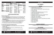
VENTED ENCLOSURES<br />
NOTE: Vb is the gross volume, which is the TOTAL internal volume, before any speaker and/or port displacement.<br />
All external dimensions were based on the use of 3/4" (1.90cm) materials.<br />
NOTE: When using enclosures other than recommended, call Technical Support for correct application.<br />
P<br />
W<br />
D<br />
H<br />
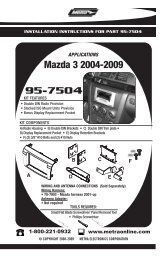
Optimum Enclosure Sizes<br />
VENTED ENCLOSURES 12" 15"<br />
<strong>T2</strong>D212 / <strong>T2</strong>D412 <strong>T2</strong>D215 / <strong>T2</strong>D415<br />
Vb- Internal Area cu. ft. 2.0 2.75<br />
( Liter)<br />
(56.63)<br />
(77.87)<br />
F b - Tuning Frequency (Hz) 40.0 36.0<br />
F 3 - -3dB Point (Hz) 32.0 29.0<br />
H - Height-inch 16.5 17.5<br />
( cm)<br />
(41.91)<br />
(44.45)<br />
W - Width-inch 25.5 27.5<br />
( cm)<br />
(64.77)<br />
(69.85)<br />
D - Depth-inch 12.5 15.25<br />
( cm)<br />
(31.75)<br />
(38.74)<br />
P - Port Diameter and<br />
Length-inch (3) 3 x 14 (1) 6 x 17<br />
(cm) (3) (7.62 x 35.56) (1) (15.24 x 43.18)<br />
SEALED ENCLOSURES 12" 15"<br />
<strong>T2</strong>D212 / <strong>T2</strong>D412 <strong>T2</strong>D215 / <strong>T2</strong>D415<br />
Vb- Internal Area cu. ft. 1.0 2.0<br />
( Liter)<br />
(28.32)<br />
(56.63)<br />
Number of ports noted in ( )<br />
Specifications subject to change without notice<br />
NOTE: The port shown can be placed on any face of the enclosure as long as the port ends are not obstructed.<br />
NOTE: When using vented enclosures, for maximum reliability and power handling ensure that a subsonic or "infrasonic" filter is used so that<br />
only usable low frequency signal is sent to the subwoofer.<br />
C<br />
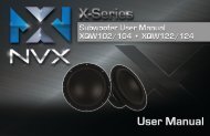
“ HIGH OUTPUT ” SLOT LOADED ENCLOSURES<br />
D<br />
E<br />
3/4" MDF<br />
A<br />
F<br />
B<br />
VENTED ENCLOSURES 12" 15"<br />
<strong>T2</strong>D212 / <strong>T2</strong>D412 <strong>T2</strong>D215 / <strong>T2</strong>D415<br />
Vb- Box Volume Net / Gross - cu. ft. 2.25 / 3.12 3.25 / 4.22<br />
( Liter)<br />
(63.71 / 88.35)<br />
(92.03 / 119.50)<br />
F b - Tuning Frequency (Hz) 40.0 38.0<br />
A - Width-inch 30.0 30.0<br />
( cm)<br />
(76.20)<br />
(76.20)<br />
B - Height-inch 15.25 18.0<br />
( cm)<br />
(38.74)<br />
(45.72)<br />
C - Depth-inch 15.25 17.0<br />
( cm)<br />
(38.74)<br />
(43.18)<br />
D - Port area and<br />
Length-inch (1) 3 x 13.75 x 25.75 (1) 3 x 16.5 x 22.5<br />
(cm) (1) (7.62 x 34.93 x 65.41) (1) (7.62 x 41.91 x 57.15)<br />
E - Length-inch 14.25 9.25<br />
( cm)<br />
(36.20)<br />
(23.50)<br />
F - Mounting Diameter-inch 10-13/16 13-13/16<br />
( cm)<br />
(27.46)<br />
(35.08)<br />
Cut List<br />
Baffle / Back-inch<br />
( cm)<br />
Number of ports noted in ( )<br />
3<br />
30 x 15.25 30 x 18<br />
(76.20 x 38.74)<br />
(76.20 x 45.72)<br />
Top / Bottom-inch 30 x 13.75 30 x 15.5<br />
( cm)<br />
(76.20 x 34.93)<br />
(76.20 x 39.37)<br />
Ends -inch 13.75 x13.75 15.5 x 16.5<br />
( cm)<br />
(34.93 x 34.93)<br />
(39.37 x 41.91)<br />
Port -inch 13.75 x 13.5 - 13.75 x10.75 8.5 x 16.5 - 12.5 x 16.5<br />
( cm)<br />
(34.93 x 34.29 - 34.93 x 27.31) (21.59 x 41.91 - 31.75 x 41.91)<br />
Specifications subject to change without notice
Model - Power D<strong>VC</strong> <strong>T2</strong>D212 <strong>T2</strong>D412 <strong>T2</strong>D215 <strong>T2</strong>D415<br />
Nominal Impedance (ohms) 2 (2) 4 (2) 2 (2) 4 (2)<br />
Voice Coil Diameter-inch (mm) 4 (101.6) 4 (101.6) 4 (101.6) 4 (101.6)<br />
FS<br />
( Hz)<br />
QTS<br />
WIRING CONFIGURATIONS<br />
By varying the wiring configuration of your speakers you can create an<br />
impedance load to match your system.Altering the wiring configurations<br />
gives a range of options for impedance loads. Series, Parallel, or<br />
Series-Parallel wiring configurations are different techniques for wiring<br />
speakers that provide different loads. Series configuration is a string<br />
method where speakers are wired end to end. Parallel configuration<br />
uses two or more speakers wired across common terminals.<br />
Series-Parallel configuration combines both techniques. Choose the<br />
wiring diagram that corresponds to the number of woofers and the<br />
impedance of your amplifier.<br />
SUBWOOFER CROSSOVERS<br />
There are two operational types of crossovers, passive and active.<br />
Passive crossovers (coils or inductors) are placed on the speaker<br />
leads between the amplifier and speaker.An active crossover is an<br />
electronic filter that separates the audio signal fed to different<br />
amplifiers. For optimum subwoofer performance, we recommend<br />
using an active 80-100Hz low-pass crossover at 12dB/octave.<br />
SPECIFICATIONS<br />
39<br />
0.49<br />
VAS-cu.ft. (liter) 0.48 (13.6) 0.48 (13.6) 1.71 (48.4) 1.82 (51.6)<br />
Xmax-inch (mm) 0.75 (19) 0.75 (19) 0.75 (19) 0.75 (19)<br />
SPL (dB @ 1w/1m) 83.5 83.1 86.0 85.4<br />
Power Handling (RMS) 1200 1200 1200 1200<br />
Power Handling (Max) 2400 2400 2400 2400<br />
Mounting Dia.-inch (mm) 10-13/16 (274.64) 10-13/16 (274.64) 13-13/16 (350.84) 13-13/16 (350.84)<br />
Mounting Depth-inch (mm) 9 (228.60) 9 (228.60) 10 (254.00) 10 (254.00)<br />
Speaker Dis.-cu. ft. (liter) 0.151 (4.28) 0.151 (4.28) 0.176 (4.98) 0.176 (4.98)<br />
Sealed Box Vol.-cu. ft. (liter) 1.0 (28.32) 1.0 (28.32) 2.0 (56.63) 2.0 (56.63)<br />
Vented Box Vol.-cu. ft. (liter) 2.0 (56.63) 2.0 (56.63) 2.75 (77.75) 2.75 (77.75)<br />
Port Diameter & Length (in.) (3) 3 x 14 (3) 3 x 14 (1) 6 x 17 (1) 6 x 17<br />
Port Diameter & Length (cm) (3) 7.62 x 35.56 (3) 7.62 x 35.56 (1) 15.24 x 43.18 (1) 15.24 x 43.18<br />
5<br />
40<br />
0.59<br />
31<br />
0.52<br />
31<br />
0.62<br />
Specifications subject to change without notice
Français<br />
MISE EN GARDE : avant d'entamer l'installation, déconnectez la<br />
broche négative (-) de la batterie pour éviter tout risque de blessures,<br />
d’incendie ou de dommages à l'appareil.<br />
PRATIQUEZ UNE ÉCOUTE SANS RISQUES MD<br />
Une exposition continue à des niveaux de pression acoustique supérieurs<br />
à 100 dB peut causer une perte d'acuité auditive permanente. Les<br />
systèmes audio de forte puissance pour auto peuvent produire des<br />
niveaux de pression acoustique bien au-delà de 130 dB. Faites preuve de<br />
bon sens et pratiquez une écoute sans risques<br />
Enceintes recommandées<br />
Ce manuel décrit deux types particuliers d'enceintes aux performances tout à fait<br />
distinctes. Cette section vous permettra de décider celui qui vous conviendra le<br />
mieux.<br />
Enceintes Étanches<br />
Les enceintes étanches sont les plus faciles à fabriquer. À cet égard, la chose la plus<br />
importante dans leur fabrication est de vous assurer qu'elles sont vraiment<br />
hermétiques.Appliquez de la colle et un produit d'étanchéité sur tous les joints<br />
pour solidifier l'ensemble et empêcher toute fuite d'air. Le volume du caisson influe<br />
directement sur la performance du haut-parleur. Les enceintes de plus grande<br />
dimension délivrent une réponse uniforme en fréquence avec des graves profonds<br />
alors que les enceintes plus petites ont une courbe de réponse plus prononcée et<br />
un rendement généralement supérieur pour un niveau de pression acoustique plus<br />
élevé.<br />
Avantage des enceintes étanches :<br />
• Petites enceintes<br />
• Réponse linéaire (uniforme)<br />
• Pas de bruit d'évent<br />
• Puissance élevée sur toutes les fréquences<br />
• Excellentes en ce qui concerne la qualité du son<br />
Enceintes À Évent<br />
Les enceintes à évent se distinguent des enceintes étanches du fait qu'on y ajoute<br />
un évent ou port pour les « accorder ». Les enceintes recommandées sont<br />
conçues pour offrir d'excellentes performances. Il est généralement plus facile<br />
d'accorder les caissons plus grands pour l'obtention de basses fréquences et les<br />
caissons moyens et petits pour des fréquences plus élevées. Les enceintes à évent<br />
ont une réponse moins linéaire que les enceintes étanches mais dégagent<br />
nettement plus de puissance à la fréquence d'accord.<br />
Avantages des enceintes à évent :<br />
• Rendement moyen supérieur par rapport aux modèles étanches<br />
• La fréquence d'accord peut être facilement réglée en changeant la longueur<br />
de l'évent<br />
• Reproduction profonde des basses avec une puissance d'entrée moindre<br />
• Excellent choix pour un rendement élevé à faible puissance d'entrée<br />
Construire Un Caisson<br />
Pour fonctionner convenablement les parois du caisson doivent être rigides<br />
lorsqu'elles sont soumises aux hautes pressions dues au fonctionnement du<br />
haut-parleur. Nous vous recommandons d'utiliser des panneaux de bois aggloméré<br />
à haute ou moyenne densité de particules de type “MDF”. Ces panneaux sont<br />
disponibles dans la plupart des magasins de bricolage. Pour un caisson de grand<br />
volume il est recommandé de placer des renforts à l'intérieur du caisson. Les<br />
différents côtés devront être collés (colle à bois) et vissés (ou éventuellement<br />
cloués). Il est recommandé de mettre un joint de silicone dans les arêtes internes<br />
du caisson afin d'éviter les fuites d'air.<br />
Calcu du Volume<br />
On calcule le volume en mesurant la dimension de chaque côté et en utilisant la<br />
formule suivante:<br />
Volume du caisson Hauteur (cm) x Longueur (cm) x Largeur (cm)<br />
Divisé près (Litres) 1000<br />
Si les due côtés qui se font face n'ont pas la même longueur, additionnez les et<br />
divisez le résultat par deux pour obtenir la moyenne des deux longueurs. Utilisez<br />
le nombre ainsi obtenu dans la formule pour déterminer le litrage. Cette méthode<br />
6<br />
permet d'obtenir le volume du caisson sans devoir faire de calculs compliqués de<br />
section de volume. L'épaisseur du matériau dont est fait le caisson réduit le volume<br />
interne de celui-ci. Lorsqu'on mesure les côtés du caisson il ne faut donc pas<br />
oublier d'oter des mesures l'epaisseur du matériau. Le haut-parleur lui-même<br />
diminue le volume interne du caisson. Le volume d'air déplacé par chaque modèle<br />
de haut-parleur est repris dans les spécifications techniques et doit également être<br />
soustrait du volume total.<br />
Configuration du câblage<br />
En variant la configuration du câblage de vos haut-parleurs, vous pouvez créer<br />
une charge d'impédance correspondant à votre système. La modification des<br />
configurations de câblage offre tout un choix d'options en ce qui concerne la<br />
charge d'impédance. Les câblages série, parallèle, ou série/parallèle sont des<br />
techniques permettant de câbler les haut-parleurs de manière à produire des<br />
charges différentes. La configuration série consiste à câbler les haut-parleurs à<br />
la chaîne, bout à bout. La configuration parallèle utilise deux ou plusieurs<br />
haut-parleurs branchés sur des bornes communes. La configuration série/parallèle<br />
combine les deux techniques. Choisissez le schéma ci-dessous qui correspond au<br />
nombre de haut-parleurs de graves et à l'impédance de votre ampli.<br />
Filtres de subwoofer<br />
On distingue deux types de filtres opérationnels : passif et actif. Les filtres passifs<br />
(bobines ou inducteurs) sont placés sur les fils de haut-parleur, entre l'ampli et le<br />
haut-parleur. Un filtre actif est un filtre électronique qui sépare le signal audio<br />
envoyé à différents amplis. Pour obtenir une performance optimale du subwoofer,<br />
nous recommandons l'utilisation d'un filtre actif passe-bas 80-100 Hz à 12<br />
dB/octave.<br />
Español<br />
PRECAUCIÓN: Antes de la instalación, desconecte el terminal<br />
negativo de la batería (-) para prevenir daño a la unidad, incendio y/o<br />
posibles lesiones.<br />
PRACTIQUE EL SONIDO SEGURO<br />
El contacto continuo con niveles de presión de sonido superiores a 100 dB<br />
puede causar la pérdida permanente de la audición. Los sistemas de sonido para<br />
automóviles de alta potencia pueden producir niveles de presión de sonido<br />
superiores a los 130 dB. Use su sentido común y practique el sonido seguro.<br />
Cajas recomendadas<br />
Este manual delinea dos tipos específicos de cajas que producen rendimientos<br />
inconfundiblemente diferentes. Esta sección es para ayudarle a decidir cuál tipo es<br />
el mejor para su aplicación.<br />
Cajas CERRADAS<br />
Las cajas cerradas son las más fáciles de hacer. La parte más importante de la<br />
construcción de una caja cerrada es garantizar su hermetismo. El uso de pegante y<br />
algún tipo de sellador en todos los bordes garantizará una construcción sólida y<br />
evitará fugas de aire. El volumen de la caja impacta directamente el rendimiento<br />
del altavoz. Las cajas más grandes ofrecen una respuesta más plana y un bajo más<br />
profundo, mientras que las más pequeñas ofrecen un incremento en la curva de<br />
respuesta y generalmente una salida mayor, para un mayor NPS.<br />
Ventajas de las cajas cerradas:<br />
• Cajas pequeñas<br />
• Respuesta lineal (plana)<br />
• No hay ruido del orificio<br />
• Capacidad de alta potencia en todas las frecuencias<br />
• Excelentes para la calidad del sonido<br />
Cajas con Orificios<br />
Las cajas con orificios sólo se diferencian de las cerradas en que se les hace un<br />
orificio para "sintonizarlas." Las cajas recomendadas son diseñadas para un gran<br />
rendimiento general. Las cajas grandes tienden a ser fáciles de sintonizar en las<br />
frecuencias graves, mientras que medianas y pequeñas son más fáciles de sintonizar<br />
en las frecuencias más altas. El diseño con orificios es de una respuesta menos<br />
lineal que el de la caja cerrada, pero tiene una salida notablemente mayor en la<br />
frecuencia de sintonización.<br />
Ventajas de las cajas con orificios:<br />
• Un promedio de salida mayor que las cerradas<br />
• La frecuencia de sintonización se ajusta fácilmente al cambiar la longitud del<br />
orificio
• Respuesta de bajo profundo con menos exigencia de potencia<br />
• Fabulosas para salida alta con potencia limitada<br />
Construcción de una caja<br />
Para un buen funcionamiento las paredes de la caja deben ser rigidas y no<br />
se deben doblar cuando sean sometidas a la gran presión que ejerce el<br />
funcionamiento del altavoz. Recomendamos usar madera comprimida de mediana<br />
densidad, de 1.9 cm o fibra de media densidad. Si la caja es muy grande es<br />
necessario reforzarla internamente. Las juntas deben ser encoladas y aseguradas<br />
con tornillos o grapas. Internamente los bordes deben ser sellados con silicona<br />
para prevenir las fugas de aire. La cola para madera es la mejor opción.<br />
Cálculo de Volúmenes<br />
Para calcular el volumen sólo se han de medir las dimensiones en centímetros y<br />
aplicar la fórmula:<br />
Volumen du la caja Alto(cm) x Ancho(cm) x Profundidad(cm)<br />
Dividido por (en litros) 1000<br />
Si dos caras opuestas son de diferente tamaño, súmelas y divida el total por<br />
dos para obtener el promedio. Usando esta técnica se ahorrara el cálculo por<br />
secciones. El espesor del material con que está construida la caja reduce el<br />
volumen interno, de manera que ha de restarse de las dimensiones exteriores para<br />
determinar el volumen interior. La cantidad de aire que ocupa cada modelo viene<br />
especificado en la hoja de características y también debe sustraerse para obtener<br />
el volumen neto interior.<br />
Configuraciones del cableado<br />
Al variar la configuración del cableado de los altavoces, usted puede crear una<br />
impedancia de carga que iguale a su sistema. La alteración de la configuración de<br />
los cables da una gama de opciones para impedancia de carga. Las configuraciones<br />
en serie, paralela o en serie-paralela son técnicas diferentes para el cableado de los<br />
altavoces que ofrecen cargas diferentes. La configuración en serie es un método en<br />
cadena en el que los altavoces se conectan de punta a punta. La configuración<br />
paralela usa dos o más altavoces conectados a lo largo de terminales en común. La<br />
configuración en serie-paralela combina ambas técnicas. Escoja el diagrama que<br />
corresponda al número de altavoces para sonidos graves y la impedancia de su<br />
amplificador<br />
Filtros de Transición del altavoz para sonidos graves<br />
(Subwoofer X-Over)<br />
Hay dos tipos funcionales de filtros de transición, pasivos y activos. Los pasivos<br />
(bobinas o inductores) se conectan a los cables del altavoz, entre el amplificador y<br />
el altavoz. Un filtro de transición activo es un filtro electrónico que separa la señal<br />
de audio alimentada a diferentes amplificadores. Para un rendimiento óptimo del<br />
altavoz para sonidos graves, recomendamos el uso de un filtro de transición activo<br />
de 80-100Hz, paso bajo a 12dB/octava.<br />
Deutsch<br />
VORSICHT: Entfernen Sie vor dem Einbau den negative Batteriepol,<br />
um Schäden am Gerät, Feuer bzw. mögliche Verletzungen zu vermeiden.<br />
PRAKTIZIEREN SIE SICHEREN SOUND<br />
Fortgesetzte Geräuschdruckpegel von über 100 dB können beim Menschen zu<br />
permanentem Hörverlust führen. Leistungsstarke Autosoundsysteme können<br />
Geräuschdruckpegel erzeugen, die weit über 130 dB liegen. Bitte wenden Sie<br />
gesunden Menschenverstand an und praktizieren Sie sicheren Sound.<br />
Empfohlene Gehäuse<br />
Diese Anleitung beschreibt zwei spezifische Typen von Gehäusen, die grundsätzlich<br />
verschiedene Performancemerkmale bieten. Dieser Abschnitt soll Ihnen dabei<br />
helfen zu entscheiden, welcher der beste Typ für Ihre Anwendung ist.<br />
Geschlossene Gehäuse<br />
Geschlossene Gehäuse lassen sich am leichtesten bauen. Der wichtigste Aspekt<br />
beim Bau eines geschlossenen Gehäuses ist zu gewährleisten, dass es luftdicht ist.<br />
Die Verwendung von Klebstoff und anderen Dichtungsmitteln an allen Fugen<br />
gewährleistet eine solide Konstruktion und verhindert Luftverlust. Das<br />
Gehäusevolumen wirkt sich unmittelbar auf die Performance des Lautsprechers<br />
aus. Größere Gehäuse bieten eine flachere Reaktion und tiefere Bässe, wohingegen<br />
7<br />
kleinere Gehäuse eine Abweichung in der Reaktionskurve bieten und im<br />
Allgemeinen durch höhere Leistung zu einem höheren Schalldruckpegel führen.<br />
Vorteile von geschlossenen Gehäusen:<br />
• Kleine Gehäuse<br />
• Lineare (flache) Reaktion<br />
• Keine Öffnungsgeräusche<br />
• Hohe Nennbelastbarkeit in allen Frequenzbereichen<br />
• Ausgezeichnete Klangqualität<br />
Belüftete Gehäuse<br />
Belüftete Gehäuse unterscheiden sich von geschlossenen Gehäusen nur in sofern,<br />
als dass ein Luftschlitz bzw. eine Öffnung hinzugefügt wird, um das Gehäuse zu<br />
„stimmen“. Die empfohlenen Gehäuse sind für hervorragende Gesamtperformance<br />
konstruiert. Größere Gehäuse lassen sich in der Regel leichter auf niedrigere<br />
Frequenzen abstimmen, wohingegen sich mittlere und kleine Gehäuse leichter auf<br />
höhere Frequenzen abstimmen lassen. Das belüftete Design zeigt eine weniger<br />
lineare Reaktion als das geschlossene Gehäuse, erbringt jedoch eine feststellbar<br />
höhere Leistung auf der abgestimmten Frequenz.<br />
Vorteile von belüfteten Gehäusen:<br />
• Höhere Durchschnittsleistung als geschlossene Gehäuse<br />
• Abstimmfrequenz kann leicht durch Änderung der Öffnungslänge angepasst<br />
werden<br />
• Tiefes Bassverhalten bei geringerem Kraftbedarf<br />
• Gut geeignet für hohe Leistung bei beschränkter Kraft<br />
Bau des Gehäuses<br />
Um ordnungsgemäß zu funktionieren, müssen die Gehäusewände steif sein und<br />
dürfen nicht nachgeben, wenn sie dem hohen Druck ausgesetzt sind, der bei Betrieb<br />
des Lautsprechers entsteht. Für optimale Performance empfehlen wir Faserplatte<br />
mittlerer Dichte (Stärke ca. 1,9 cm) und interne Aussteifungen. Das Gehäuse wird<br />
verleimt und mit Nägeln oder Schrauben befestigt. Da Faserplatte luftdurchlässig ist,<br />
wird geraten, das Gehäuse von außen mit Polyurethan zu behandeln.<br />
Berechnung des Volumens<br />
Zur Berechnung des Volumens einfach die Maße feststellen und folgende Formel<br />
anwenden:<br />
Gehäuse-Volumen Höhe (cm) x Breite (cm) x Tiefe (cm)<br />
Vorbei geteilt (Liter) 1000<br />
Sind zwei gegenüber liegende Seiten ungleich lang, die Durchschnittslänge der<br />
beiden Seiten berechnen. Das Volumen lässt sich mithilfe dieser Zahl berechnen,<br />
ohne das Gehäuse in Abschnitten berechnen zu müssen. Die Stärke des<br />
Resonanzwandmaterials reduziert das Innenvolumen und muss daher zur<br />
Feststellung des Innenvolumens vom Außenvolumen subtrahiert werden. Der<br />
Lautsprecher selbst reduziert das Innenvolumen ebenfalls. Die Luftverdrängung für<br />
jedes Modell ist unter Technische Daten aufgeführt und muss bei der<br />
Gesamtkalkulation des Volumens ebenfalls subtrahiert werden.<br />
Verkabelungskonfigurationen<br />
Durch Veränderung der Verkabelungskonfiguration Ihrer Lautsprecher können Sie<br />
eine Impedanzlast herstellen, die Ihrem System entspricht. Bietet die Veränderung<br />
der Verkabelungskonfigurationen eine Reihe von Optionen für die Impedanzlast.<br />
Reihen-, Parallel- oder Reihen-Parallel-Verkabelungen sind verschiedene Techniken<br />
für die Verkabelung von Lautsprechern, die unterschiedliche Belastungen bieten. Die<br />
Reihenkonfiguration ist eine Reihenmethode, bei der die Lautsprecher von Ende zu<br />
Ende verkabelt werden. Die Parallelkonfiguration verwendet mindestens zwei<br />
Lautsprecher, die über gemeinsame Anschlüsse verkabelt werden. Die Reihen-<br />
Parallel-Konfiguration kombiniert beide Techniken.Wählen Sie das nachfolgende<br />
Verkabelungsdiagramm aus, das der Zahl an Tieftönern und der Impedanz Ihres<br />
Verstärkers entspricht.<br />
Subwoofer-Crossover<br />
Es gibt zwei Betriebstypen für Crossover, und zwar passive und aktive. Passive<br />
Crossover (Spulen oder Induktoren) werden auf den Lautsprecherkabeln zwischen<br />
Verstärker und Lautsprecher platziert. Ein aktives Crossover ist ein elektronischer<br />
Filter, der das Audiosignal trennt, das verschiedenen Verstärkern zugeführt wird.<br />
Zur optimalen Subwoofer-Performance empfehlen wir die Verwendung von aktiven<br />
80-100 Hz-Niedrigpass-Crossovern bei 12 dB/Oktav.
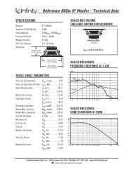
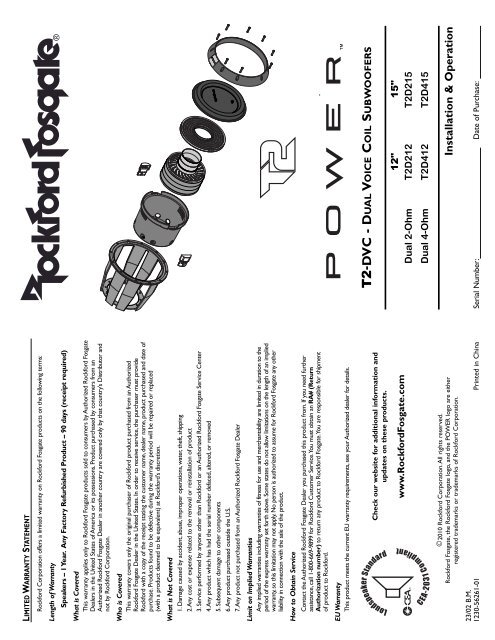
Custom insulated / isolated<br />
compression input terminal<br />
assembly<br />
Rigid die-cast aluminum frame<br />
Optimized motor magnetics<br />
with extended vented pole<br />
and bumped backplate<br />
• Hard anodized aluminum dust cap.<br />
• Hard anodized aluminum cone.<br />
• Tear & fatigue resistant poly-cotton spider.<br />
• High density Santoprene surround.<br />
FEATURES<br />
• Ultra-High temp aluminum voice coil with spun-laced Nomex insulating reinforcement collar.<br />
• Optimized motor magnetics with extended vented pole and bumped backplate.<br />
• Triple stack ferrite magnet structure.<br />
• Fatigue resistant and reduced strain "stitched on" flexible lead wire design.<br />
• Multi-point high-temp/high-strength neck joint bonding technique.<br />
• Rigid die-cast aluminum frame.<br />
• Die-cast motor case / heat sink.<br />
• Custom insulated/isolated compression input terminal assembly.<br />
• Proprietary spider venting/cooling technique.<br />
• IDHS Inductive Damping Heat Sink.<br />
Die-cast motor case / heat sink<br />
Hard anodized aluminum cone<br />
and hard anodized aluminum<br />
dust cap<br />
Removable and reversible<br />
screw concealing ring<br />
• Removable and reversible screw concealing ring.<br />
8<br />
Triple stack ferrite magnet structure<br />
IDHS Inductive Damping Heat Sink<br />
Ultra-High temp aluminum voice coil<br />
with spun-laced Nomex insulating<br />
reinforcement collar<br />
Tear and fatigue resistant<br />
poly-cotton spider<br />
High density<br />
Santoprene<br />
surround