556U Immobilizer Interface - Sonic Electronix
556U Immobilizer Interface - Sonic Electronix
556U Immobilizer Interface - Sonic Electronix

Create successful ePaper yourself
Turn your PDF publications into a flip-book with our unique Google optimized e-Paper software.
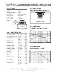
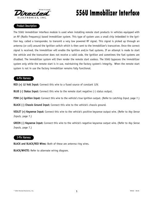
Product Description<br />
The <strong>556U</strong> immobilizer interface module is used when installing remote start products in vehicles equipped with<br />
an RF (Radio Frequency) based immobilizer system. This type of system uses a small chip imbedded in the ignition<br />
key, called a transponder, to transmit a very low powered RF signal. This signal is picked up through an<br />
antenna (or coil) around the ignition switch which is then sent to the immobilizer’s transceiver. Once the correct<br />
signal is received, the immobilizer will enable the ignition and/or fuel systems. If an attempt is made to start<br />
the vehicle and the transceiver does not receive a valid code, the ignition and sometimes the fuel systems are<br />
disabled. The immobilizer system will then render the remote start useless. The <strong>556U</strong> bypasses the immobilizer<br />
system only while the remote start is in use, maintaining the factory system’s integrity. When the remote start<br />
system is not in use the factory immobilizer remains fully functional.<br />
6-Pin Harness<br />
RED (+) 12 Volt Input: Connect this wire to a fused source of constant 12V.<br />
BLUE (-) Status Input: Connect this wire to the remote start negative (-) status output.<br />
PINK (+) Ignition Input: Connect this wire to the vehicle’s true ignition output. (Refer to Latching Input, page 7.)<br />
BLACK (-) Chassis Ground Input: Connect this wire to the vehicle’s chassis ground.<br />
VIOLET (+) Keysense Input: Connect this wire to the vehicle’s positive keysense output wire. (Refer to Key Sense<br />
Inputs, page 7.)<br />
GREEN (-) Keysense Input: Connect this wire to the vehicle’s negative keysense output wire. (Refer to Key Sense<br />
Inputs, page 7.)<br />
3-Pin Harness<br />
BLACK and BLACK/RED Wires: Both of these are antenna ring wires.<br />
BLACK/WHITE: Refer to alternate wiring diagram.<br />
<strong>556U</strong> <strong>Immobilizer</strong> <strong>Interface</strong><br />
© 2004 Directed Electronics, Inc. 1<br />
N<strong>556U</strong> 09/04
<strong>Immobilizer</strong> <strong>Interface</strong> Instructions<br />
Please note that the instructions outlined in the Standard <strong>Immobilizer</strong> <strong>Interface</strong> section describe an immobilizer<br />
interface that will work with the majority of vehicles; however, some vehicle immobilizer systems may require an<br />
alternate interface due to mounting issues, cosmetic differences, or RF loss when coupling the factory key RF<br />
with the <strong>556U</strong> to the factory transponder ring. (See Alternate <strong>Immobilizer</strong> <strong>Interface</strong>.)<br />
IIMMPPOORRTTAANNTT!! Before beginning the installation inform the customer that one of the vehicle’s<br />
coded keys must be used in the installation and installed permanently in the unit. If a new key<br />
is being purchased through the dealer, make sure to code the new key to the factory immobilizer<br />
or have the dealer do this. In many vehicles, the new key must be coded at the dealer.<br />
IIMMPPOORRTTAANNTT!! It is also the installer's responsibility to notify customers of the following: If they<br />
wish to have additional keys programmed to the vehicle's immobilizer system in the future,<br />
certain vehicle manufacturers require that all programmed keys be reprogrammed at the time<br />
that the keys being added to the system are programmed. In this case, it would be necessary to<br />
remove the already programmed key from the <strong>556U</strong> module to reprogram it. (If the customer<br />
plans on having additional keys programmed to the vehicle in the future, the shaft of the key<br />
should not be altered.)<br />
© 2004 Directed Electronics, Inc. 2<br />
N<strong>556U</strong> 09/04
Standard <strong>Immobilizer</strong> <strong>Interface</strong><br />
1. Open the control module and place the vehicle’s coded key through the center of the black receiver ring as shown.<br />
2. Reassemble the control module. This will secure the key inside.<br />
IIMMPPOORRTTAANNTT!! When using the ring method of installing the <strong>556U</strong>, the ring from the <strong>556U</strong> MUST<br />
be in front of the factory receiver ring. It CAN NOT be on top of, or behind the factory receiver<br />
ring. See illustration below.<br />
3. Disassemble the steering column shroud and place the antenna ring around the vehicle’s ignition switch as<br />
shown, and plug into the control module.<br />
4. Plug the 6-pin power plug into the control module.<br />
5. Connect the BLACK wire to chassis (ground).<br />
6. Connect the red wire to a fused source of constant 12V.<br />
7. Connect the blue wire to the status output (blue wire) of the remote start system that provides a latched<br />
negative (-) ground while the remote start is active.<br />
8. Test unit before reassembling the steering column.<br />
9. Reassemble the steering column shroud.<br />
© 2004 Directed Electronics, Inc. 3<br />
N<strong>556U</strong> 09/04
INCORRECT CORRECT<br />
© 2000 Directed Electronics, Inc. 4<br />
N<strong>556U</strong> 5/00
Alternate <strong>Immobilizer</strong> <strong>Interface</strong> No. 1<br />
This type of interface will only work with immobilizer systems that have a two-wire factory antenna harness. This<br />
alternate interface method is not guaranteed to work with all immobilizer systems, due to differences in<br />
transponder systems. It is meant to provide the installer with an alternative interface method for most two-wire<br />
transponder ring systems. This method will not work on European vehicles.<br />
1. Open the control module and place the vehicle’s coded key through the center of the black receiver ring as shown.<br />
2. Reassemble the control module to secure the key inside.<br />
3. Disassemble the steering column shroud and locate the factory transponder ring’s antenna wires. The two<br />
wires are usually located in a tube routing from the transponder ring to the factory transceiver module.<br />
NNOOTTEE:: Some vehicles may require other methods to access the factory transponder ring antenna<br />
wires.<br />
© 2004 Directed Electronics, Inc. 5<br />
N<strong>556U</strong> 09/04
4. Plug the three-pin connector into the <strong>556U</strong> module and cut the <strong>556U</strong>’s antenna wire off. Discard the antenna<br />
ring.<br />
5. Split open the factory transponder ring tube and cut one of the two wires in half.<br />
6. Connect the factory transponder ring side of the cut wire to the BLACK/WHITE normally closed input wire of<br />
the <strong>556U</strong>.<br />
7. Connect the factory transceiver module side of the cut wire to the <strong>556U</strong>’s BLACK wire.<br />
8. Connect the BLACK/RED wire to the uncut factory transponder ring antenna wire.<br />
9. Plug the 6-pin power plug into the control module.<br />
10 Connect the BLACK wire to chassis ground.<br />
11. Connect the RED wire to a fused source of constant 12V.<br />
12. Connect the BLUE wire to the status output (blue wire) of the remote start system that provides a latched<br />
negative (-) ground while the remote start is active.<br />
13. Test unit before reassembling the steering column.<br />
14. Reassemble the steering column shroud.<br />
© 2004 Directed Electronics, Inc. 6<br />
N<strong>556U</strong> 09/04
Alternate <strong>Immobilizer</strong> <strong>Interface</strong> No. 2<br />
This type of interface will only work with immobilizer systems that have a two-wire factory antenna harness. This<br />
alternate interface method is not guaranteed to work with all immobilizer systems, due to differences in<br />
transponder systems. It is meant to provide the installer with an alternative interface method for most two-wire<br />
transponder ring systems. This method will work on European vehicles.<br />
1. Open the control module and place the vehicle’s coded key through the center of the black receiver ring as shown.<br />
2. Reassemble the control module to secure the key inside.<br />
3. Disassemble the steering column shroud and locate the factory transponder ring’s antenna wires. The two<br />
wires are usually located in a tube routing from the transponder ring to the factory transceiver module.<br />
NNOOTTEE:: Some vehicles may require other methods to access the factory transponder ring antenna<br />
wires.<br />
© 2004 Directed Electronics, Inc. 7<br />
N<strong>556U</strong> 09/04
4. Plug the three-pin connector into the <strong>556U</strong> module and cut the <strong>556U</strong>’s antenna wire off. Discard the antenna<br />
ring.<br />
5. Split open the factory transponder ring tube and cut one of the two wires in half.<br />
6. Connect the factory transponder ring side of the cut wire to the BLACK/WHITE normally closed input wire of<br />
the <strong>556U</strong>.<br />
7. Connect the factory transceiver module side of the cut wire to the <strong>556U</strong>’s BLACK wire.<br />
8. Connect the BLACK/RED and BLACK/WHITE wires to the factory transponder ring side of the cut wire.<br />
9. Plug the 6-pin power plug into the control module.<br />
10 Connect the BLACK wire to chassis ground.<br />
11. Connect the RED wire to a fused source of constant 12V.<br />
12. Connect the BLUE wire to the status output (blue wire) of the remote start system that provides a latched<br />
negative (-) ground while the remote start is active.<br />
13. Test unit before reassembling the steering column.<br />
14. Reassemble the steering column shroud.<br />
Vehicle Applications<br />
The <strong>556U</strong> works with most RF based immobilizer systems. Refer to DirectWire for specific applications.<br />
Jumper Settings<br />
The <strong>556U</strong> is shipped with the jumper set in a 60 winding position (mode 2). For most applications this should<br />
be the optimal setting. Moving the jumper will set the <strong>556U</strong> to work off of a 18 winding position (mode 1). You<br />
may use the 18 winding for American and Asian vehicles, but for European vehicles the 60 winding setting is<br />
required. Mode 2 jumper position will be more sensitive to picking up the key vice mode 1 jumper position.<br />
Key Sense Inputs<br />
Some vehicles require the vehicle never “read” two keys at the same time (Ford Escape, Mazda Tribute). These<br />
vehicles require the key sense wire to be located in the vehicle. This wire will show either ground (-) or positive<br />
(+) voltage when the key is slid in the ignition and the key chime sounds. Depending on the polarity of the<br />
vehicle attach either the GREEN (-) or the VIOLET (+) wire from the <strong>556U</strong> to the key sense wire in the vehicle.<br />
When the <strong>556U</strong> senses an input on these wires it will drop out immediately allowing the vehicle to only see the<br />
key that was just placed in the ignition cylinder.<br />
Latching Input<br />
Some vehicles require that the key code does not change during a run cycle (Mercedes ML series). By attaching<br />
the PINK wire from the <strong>556U</strong> to the ignition wire in the vehicle, the <strong>556U</strong> will stay engaged the entire time the<br />
vehicle is running. This includes after the take-over with the key. With the PINK wire of the <strong>556U</strong> attached to<br />
the ignition in the vehicle, the <strong>556U</strong> will stay engaged until the vehicle is shut off.<br />
© 2004 Directed Electronics, Inc. 8<br />
N<strong>556U</strong> 09/04
© 2004 Directed Electronics, Inc. 9<br />
N<strong>556U</strong> 09/04