556U Immobilizer Interface - Sonic Electronix
556U Immobilizer Interface - Sonic Electronix
556U Immobilizer Interface - Sonic Electronix
You also want an ePaper? Increase the reach of your titles
YUMPU automatically turns print PDFs into web optimized ePapers that Google loves.
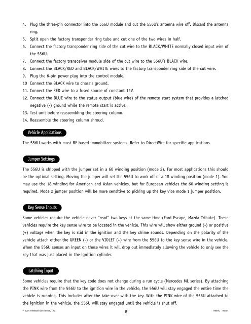
4. Plug the three-pin connector into the <strong>556U</strong> module and cut the <strong>556U</strong>’s antenna wire off. Discard the antenna<br />
ring.<br />
5. Split open the factory transponder ring tube and cut one of the two wires in half.<br />
6. Connect the factory transponder ring side of the cut wire to the BLACK/WHITE normally closed input wire of<br />
the <strong>556U</strong>.<br />
7. Connect the factory transceiver module side of the cut wire to the <strong>556U</strong>’s BLACK wire.<br />
8. Connect the BLACK/RED and BLACK/WHITE wires to the factory transponder ring side of the cut wire.<br />
9. Plug the 6-pin power plug into the control module.<br />
10 Connect the BLACK wire to chassis ground.<br />
11. Connect the RED wire to a fused source of constant 12V.<br />
12. Connect the BLUE wire to the status output (blue wire) of the remote start system that provides a latched<br />
negative (-) ground while the remote start is active.<br />
13. Test unit before reassembling the steering column.<br />
14. Reassemble the steering column shroud.<br />
Vehicle Applications<br />
The <strong>556U</strong> works with most RF based immobilizer systems. Refer to DirectWire for specific applications.<br />
Jumper Settings<br />
The <strong>556U</strong> is shipped with the jumper set in a 60 winding position (mode 2). For most applications this should<br />
be the optimal setting. Moving the jumper will set the <strong>556U</strong> to work off of a 18 winding position (mode 1). You<br />
may use the 18 winding for American and Asian vehicles, but for European vehicles the 60 winding setting is<br />
required. Mode 2 jumper position will be more sensitive to picking up the key vice mode 1 jumper position.<br />
Key Sense Inputs<br />
Some vehicles require the vehicle never “read” two keys at the same time (Ford Escape, Mazda Tribute). These<br />
vehicles require the key sense wire to be located in the vehicle. This wire will show either ground (-) or positive<br />
(+) voltage when the key is slid in the ignition and the key chime sounds. Depending on the polarity of the<br />
vehicle attach either the GREEN (-) or the VIOLET (+) wire from the <strong>556U</strong> to the key sense wire in the vehicle.<br />
When the <strong>556U</strong> senses an input on these wires it will drop out immediately allowing the vehicle to only see the<br />
key that was just placed in the ignition cylinder.<br />
Latching Input<br />
Some vehicles require that the key code does not change during a run cycle (Mercedes ML series). By attaching<br />
the PINK wire from the <strong>556U</strong> to the ignition wire in the vehicle, the <strong>556U</strong> will stay engaged the entire time the<br />
vehicle is running. This includes after the take-over with the key. With the PINK wire of the <strong>556U</strong> attached to<br />
the ignition in the vehicle, the <strong>556U</strong> will stay engaged until the vehicle is shut off.<br />
© 2004 Directed Electronics, Inc. 8<br />
N<strong>556U</strong> 09/04


