Template BA B168xh238 - bei Berner Torantriebe
Template BA B168xh238 - bei Berner Torantriebe
Template BA B168xh238 - bei Berner Torantriebe

You also want an ePaper? Increase the reach of your titles
YUMPU automatically turns print PDFs into web optimized ePapers that Google loves.
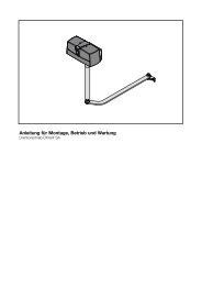
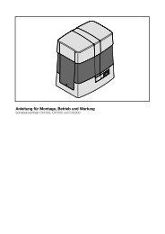
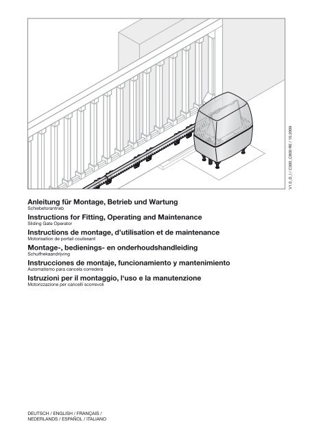
Anleitung für Montage, Betrieb und Wartung<br />
Schiebetorantrieb<br />
Instructions for Fitting, Operating and Maintenance<br />
Sliding Gate Operator<br />
Instructions de montage, d’utilisation et de maintenance<br />
Motorisation de portail coulissant<br />
Montage-, bedienings- en onderhoudshandleiding<br />
Schuifhekaandrijving<br />
Instrucciones de montaje, funcionamiento y mantenimiento<br />
Automatismo para cancela corredera<br />
Istruzioni per il montaggio, l‘uso e la manutenzione<br />
Motorizzazione per cancelli scorrevoli<br />
DEutSCh / EnGlISh / FRAnçAIS /<br />
nEDERlAnDS / ESpAñOl / ItAlIAnO<br />
V1.0_D_I / C300_C800 RE / 10.2009
DEUTSCH . . . . . . . . . . . . . . . . . . . . . . . . 6<br />
ENGLISH . . . . . . . . . . . . . . . . . . . . . . . . 23<br />
FRANÇAIS . . . . . . . . . . . . . . . . . . . . . . . 39<br />
NEDERLANDS . . . . . . . . . . . . . . . . . . . . 57<br />
ESPAÑOL . . . . . . . . . . . . . . . . . . . . . . . . 74<br />
ITALIANO . . . . . . . . . . . . . . . . . . . . . . . . 92<br />
. . . . . . . . . . . . . . . . . . . . . 110<br />
2 V1.0_D_I / C300_C800 RE / 10.2009
V1.0_D_I / C300_C800 RE / 10.2009<br />
3
4 V1.0_D_I / C300_C800 RE / 10.2009
V1.0_D_I / C300_C800 RE / 10.2009<br />
5
DEUTSCH<br />
Inhaltsverzeichnis<br />
A Mitgelieferte Artikel . . . . . . . . . . . . . . . . . . . . . . . . . . . . . . . . . . . . . . . . . . . . . . . . 3<br />
B Benötigtes Werkzeug zur Montage<br />
des Schiebetorantriebes . . . . . . . . . . . . . . . . . . . . . . . . . . . . . . . . . . . . . . . . 4<br />
C1 Montagezubehör für<br />
die Kunststoff-Zahnstangen . . . . . . . . . . . . . . . . . . . . . . . . . . . . . . . . . . 5<br />
C2 Zahnstange aus Kunststoff mit Stahlkern<br />
(Montagelasche unten) . . . . . . . . . . . . . . . . . . . . . . . . . . . . . . . . . . . . . . . . . . . 5<br />
C3 Zahnstange aus Kunststoff mit Stahlkern<br />
(Montagelasche oben) . . . . . . . . . . . . . . . . . . . . . . . . . . . . . . . . . . . . . . . . . . . . 5<br />
C4 Zahnstange aus Stahl, verzinkt . . . . . . . . . . . . . . . . . . . . . . . . . . . . . 5<br />
C5 Montagezubehör für die Stahl-Zahnstangen . . . . . . . 5<br />
Bohrschablone . . . . . . . . . . . . . . . . . . . . . . . . . . . . . . . . . . . . . . . . . . . . . . . . . . . . 129<br />
1 Zu dieser Anleitung . . . . . . . . . . . . . . . . . . . . . . . . . . . . . . . . . . . . . . . . . . . . . . . . . 7<br />
1.1 Verwendete Warnhinweise ........................................ 7<br />
1.2 Definitionen ............................................................... 7<br />
1.3 Verwendete Symbole ................................................ 8<br />
1.4 hinweise zum Bildteil ................................................ 8<br />
2 Sicherheitshinweise . . . . . . . . . . . . . . . . . . . . . . . . . . . . . . . . . . . . . . . 8<br />
2.1 Bestimmungsgemäße Verwendung .......................... 8<br />
2.2 nicht bestimmungsgemäße Verwendung ................. 8<br />
2.3 Allgemeine Sicherheitshinweise ............................... 8<br />
2.4 Sicherheitshinweise zur Montage ............................. 9<br />
2.5 Sicherheitshinweise für Elektroar<strong>bei</strong>ten .................... 9<br />
3 Montage . . . . . . . . . . . . . . . . . . . . . . . . . . . . . . . . . . . . . . . . . . . . . . . . . . . . . . . . . . . . . . . . . . . 9<br />
3.1 Montage des Schiebetorantriebs ............................. 9<br />
3.1.1 Fundament ................................................................ 9<br />
3.1.2 Ermitteln der Anbaumaße ......................................... 9<br />
3.1.3 Verankerung ............................................................ 10<br />
3.1.4 Montage des Antriebsgehäuses ............................. 10<br />
3.2 Montage der Zahnstange ....................................... 10<br />
3.3 Anschluss der netzzuleitung .................................. 10<br />
3.4 Montage des platinenhalters .................................. 10<br />
3.5 Montage des Magnethalters ................................... 10<br />
3.6 Verriegeln des Antriebes ......................................... 10<br />
3.7 Anschluss von Zusatzkomponenten/Zubehör ........ 10<br />
3.7.1 Anschluss eines externen Funk-Empfängers ......... 11<br />
3.7.2 Anschluss eines externen tasters* ......................... 11<br />
3.7.3 Anschluss eines Ausschalters zum Anhalten<br />
des Antriebs (halt- bzw. not-Aus-Kreis) ................. 11<br />
3.7.4 Anschluss einer Warnleuchte* ................................ 11<br />
3.7.5 Anschluss von Sicherheits-/Schutzeinrichtungen .. 11<br />
3.7.6 Anschluss einer universaladapterplatine uAp1* .... 11<br />
4 Inbetriebnahme . . . . . . . . . . . . . . . . . . . . . . . . . . . . . . . . . . . . . . . . . . . . . . . . . . . . . 11<br />
4.1 Vorbereitung ............................................................ 11<br />
4.2 Einlernen der torendlagen ...................................... 12<br />
4.2.1 Endlagenerfassung Tor-Zu ..................................... 12<br />
4.2.2 Endlagenerfassung Tor-Auf ................................... 12<br />
4.2.3 Endlagenerfassung Teilöffnung ............................. 12<br />
4.2.4 Abschluss des Einrichtbetriebes ............................ 12<br />
4.2.5 Referenzfahrt .......................................................... 12<br />
4.3 Kräfte lernen ........................................................... 12<br />
4.3.1 Kraftbegrenzung einstellen ..................................... 12<br />
4.3.2 Antriebsgeschwindigkeit ......................................... 13<br />
4.3.3 Kraftbegrenzung ausschalten ................................. 13<br />
4.4 Startpunkte für Schleichfahrt <strong>bei</strong>m Öffnen<br />
und Schließen ändern ............................................. 13<br />
4.5 Reversiergrenze ...................................................... 13<br />
4.6 Automatischer Zulauf .............................................. 14<br />
5 Funktionen der DIL-Schalter . . . . . . . . . . . . . . . . . . . . . . . . . . . . . . . . 14<br />
5.1 DIl-Schalter 1 ......................................................... 14<br />
5.2 DIl-Schalter 2 ......................................................... 14<br />
5.3 DIl-Schalter 3 / DIl-Schalter 4............................... 14<br />
5.4 DIl-Schalter 5 / DIl-Schalter 6............................... 14<br />
5.5 DIl-Schalter 7 ......................................................... 14<br />
5.6 DIl-Schalter 8 / DIl-Schalter 9............................... 15<br />
5.7 DIl-Schalter 10 ....................................................... 15<br />
5.8 DIl-Schalter 11 ....................................................... 15<br />
5.9 DIl-Schalter 12 ....................................................... 15<br />
5.10 DIl-Schalter 13 ....................................................... 15<br />
5.11 DIl-Schalter 14 ....................................................... 15<br />
5.12 DIl-Schalter 15 ....................................................... 15<br />
5.13 DIl-Schalter 16 ....................................................... 16<br />
6 Funk . . . . . . . . . . . . . . . . . . . . . . . . . . . . . . . . . . . . . . . . . . . . . . . . . . . . . . . . . . . . . . . . . . . . . . . . 16<br />
6.1 handsender ............................................................ 16<br />
6.1.1 Bedienelemente ...................................................... 16<br />
6.1.2 Wichtige hinweise zum Gebrauch des<br />
handsenders........................................................... 16<br />
6.1.3 Batterie einlegen/wechseln ..................................... 16<br />
6.1.4 lED-Signale des handsenders ............................... 16<br />
6.2 Funk-Empfänger ..................................................... 16<br />
6.2.1 Externer Funkempfänger ........................................ 16<br />
6.3 Einlernen der handsendertasten in den<br />
externen Empfänger ............................................... 16<br />
6.3.1 Eine tastenfunktion für Kanal 1<br />
(Impuls-Befehl) zuweisen ........................................ 16<br />
6.3.2 Eine tastenfunktion für Kanal 2<br />
(teilöffnungs-Befehl) zuweisen ............................... 16<br />
6.4 Betrieb .................................................................... 17<br />
6.5 löschen der Daten eines externen<br />
Funkempfängers ..................................................... 17<br />
7 Betrieb . . . . . . . . . . . . . . . . . . . . . . . . . . . . . . . . . . . . . . . . . . . . . . . . . . . . . . . . . . . . . . . . . . . . 17<br />
7.1 Benutzer einweisen ................................................. 17<br />
7.2 Funktionsprüfung .................................................... 17<br />
7.3 normaler Fahrbetrieb: ............................................. 17<br />
7.4 Verhalten <strong>bei</strong> einem Spannungsausfall ................... 17<br />
7.5 Verhalten nach einem Spannungsausfall ................ 17<br />
8 Prüfung und Wartung . . . . . . . . . . . . . . . . . . . . . . . . . . . . . . . . . . . . . . . . . . . 17<br />
9 Betriebs-, Fehler- und Warnmeldungen . . . . . . . . . . . . . . 18<br />
9.1 lED Gn ................................................................... 18<br />
9.2 lED Rt .................................................................... 18<br />
9.3 Fehler-/Diagnoseanzeige ........................................ 18<br />
9.4 Fehlerquittierung ..................................................... 19<br />
10 Werksreset . . . . . . . . . . . . . . . . . . . . . . . . . . . . . . . . . . . . . . . . . . . . . . . . . . . . . . . . . . . . . 19<br />
11 Demontage und Entsorgung . . . . . . . . . . . . . . . . . . . . . . . . . . . . . . . . 19<br />
12 Optionales Zubehör . . . . . . . . . . . . . . . . . . . . . . . . . . . . . . . . . . . . . . . . . . . . . . 19<br />
13 Garantiebedingungen . . . . . . . . . . . . . . . . . . . . . . . . . . . . . . . . . . . . . . . . . . . 19<br />
14 Technische Daten . . . . . . . . . . . . . . . . . . . . . . . . . . . . . . . . . . . . . . . . . . . . . . . . . 20<br />
15 Übersicht DIL-Schalter Funktionen . . . . . . . . . . . . . . . . . . . . . 21<br />
Bildteil . . . . . . . . . . . . . . . . . . . . . . . . . . . . . . . . . . . . . . . . . . . . . . . . .110-127<br />
* Zubehör, ist nicht in der Standard-Ausstattung enthalten!<br />
Weitergabe sowie Vervielfältigung dieses Dokuments, Verwertung<br />
und Mitteilung seines Inhalts sind verboten, soweit<br />
nicht ausdrücklich gestattet. Zuwiderhandlungen verpflichten<br />
zu Schadenersatz. Alle Rechte für den Fall der patent-,<br />
Gebrauchsmuster- oder Geschmacksmuster eintragung<br />
vorbehalten. Änderungen vorbehalten.<br />
6 V1.0_D_I / C300_C800 RE / 10.2009
Sehr geehrte Kundin, sehr geehrter Kunde,<br />
wir freuen uns, dass Sie sich für ein Qualitätsprodukt aus<br />
unserem hause entschieden haben.<br />
1 Zu dieser Anleitung<br />
Diese Anleitung gliedert sich in einen text- und einen Bildteil.<br />
Den Bildteil finden Sie im Anschluss an den textteil.<br />
lesen Sie die Anleitung vollständig durch, sie enthält wichtige<br />
Informationen zum produkt. Beachten Sie die hinweise und<br />
befolgen Sie insbesondere die Sicherheits- und<br />
Warnhinweise.<br />
Bewahren Sie diese Anleitung sorgfältig auf!<br />
1 .1<br />
Verwendete Warnhinweise<br />
ACHTUNG<br />
Kennzeichnet eine Gefahr, die zur Beschädigung oder<br />
Zerstörung des Produkts führen kann.<br />
Das allgemeine Warnsymbol kennzeichnet eine<br />
Gefahr, die zu Verletzungen oder zum Tod führen kann. Im<br />
textteil wird das allgemeine Warnsymbol in Verbindung mit<br />
den nachfolgend beschriebenen Warnstufen verwendet. Im<br />
Bildteil verweist eine zusätzlich Angabe auf die<br />
Erläuterungen im textteil.<br />
VORSICHT<br />
Kennzeichnet eine Gefahr, die zu leichten oder mittleren<br />
Verletzungen führen kann.<br />
WARNUNG<br />
Kennzeichnet eine Gefahr, die zum tod oder zu schweren<br />
Verletzungen führen kann.<br />
GEFAHR<br />
Kennzeichnet eine Gefahr, die unmittelbar zum tod oder zu<br />
schweren Verletzungen führt.<br />
1 .2 Definitionen<br />
Aufhaltezeit<br />
Wartezeit vor der Zufahrt des tores aus der Endlage Tor-Auf<br />
oder teilöffnung <strong>bei</strong> automatischem Zulauf.<br />
Automatischer Zulauf<br />
Selbsttätiges Schließen des tores nach Ablauf einer Zeit, aus<br />
der Endlage Tor-Auf oder teilöffnung.<br />
DIL-Schalter<br />
Auf der Steuerungsplatine befindliche Schalter zum Einstellen<br />
der Steuerung.<br />
Durchfahrtslichtschranke<br />
nach Durchfahren des tores und der lichtschranke wird die<br />
Aufhaltezeit verkürzt, so dass sich das tor kurze Zeit später<br />
schließt.<br />
Impuls-Steuerung<br />
Steuerung, die durch eine Folge von Impulsen das tor<br />
abwechselnd Auf-Stopp-Zu-Stopp fahren lässt.<br />
Kraftlernfahrt<br />
Bei dieser lernfahrt werden die Kräfte eingelernt, die für das<br />
Verfahren des tores notwendig sind.<br />
Normalfahrt<br />
Verfahren des tores mit den eingelernten Strecken und<br />
Kräften.<br />
Referenzfahrt<br />
torfahrt in Richtung Endlage Tor-Zu, um die Grundstellung<br />
festzulegen.<br />
Reversierfahrt<br />
Verfahren des tores in Gegenrichtung <strong>bei</strong>m Ansprechen einer<br />
Sicherheitseinrichtung.<br />
Reversiergrenze<br />
Die Reversiergrenze trennt den Bereich zwischen<br />
Reversierfahrt und Stoppen des tores <strong>bei</strong> Kraftabschaltung.<br />
Schleichfahrt<br />
Der Bereich in dem das tor sehr langsam verfährt, um sanft<br />
gegen die Endlage zu fahren.<br />
Selbsthaltebetrieb/Selbsthaltung<br />
Der Antrieb verfährt nach einem Impuls selbständig bis in die<br />
Endlage.<br />
Teilöffnung<br />
Der Verfahrweg, der für den personendurchgang geöffnet<br />
wird.<br />
Totmannbetrieb<br />
torfahrt, die nur so lange durchgeführt wird, wie die<br />
entsprechenden taster betätigt werden.<br />
Vollöffnung<br />
Der Verfahrweg, wenn das tor vollständig geöffnet wird.<br />
Vorwarnzeit<br />
Die Zeit zwischen dem Fahrbefehl (Impuls) und dem Beginn<br />
der torfahrt.<br />
Werksreset<br />
Zurücksetzen der eingelernten Werte in den<br />
Auslieferungszustand / die Werkseinstellung.<br />
Farbcode für Leitungen, Einzeladern und Bauteile<br />
Die Abkürzungen der Farben für leitung- und<br />
Aderkennzeichnung sowie Bauteilen folgen dem<br />
internationalen Farbcode nach IEC 757:<br />
BK Schwarz PK Rosa<br />
BN Braun RD Rot<br />
BU Blau SR Silber<br />
GD Gold TQ türkis<br />
GN Grün VT Violett<br />
GN/YE Grün/Gelb WH Weiß<br />
GY Grau YE Gelb<br />
OG Orange<br />
DEUTSCH<br />
V1.0_D_I / C300_C800 RE / 10.2009 7
DEUTSCH<br />
1 .3 Verwendete Symbole<br />
Symbole<br />
wichtiger hinweis zur Vermeidung von<br />
Sachschäden<br />
zulässige Anordnung oder tätigkeit<br />
unzulässige Anordnung oder tätigkeit<br />
siehe textteil<br />
Im Beispiel bedeutet 2 .2:<br />
siehe textteil, Kapitel 2.2<br />
siehe Bildteil<br />
siehe ggf. gesonderte Montageanleitung<br />
für not-Akku<br />
Schiebetorantrieb Standard<br />
Schiebetorantrieb verstärkte Ausführung<br />
Spannungsausfall<br />
Spannungsrückkehr<br />
hörbares Einrasten<br />
Werkseinstellung der DIl-Schalter<br />
Bauteil oder Verpackung entfernen und<br />
entsorgen<br />
1 .4 Hinweise zum Bildteil<br />
Im Bildteil wird die Antriebsmontage mit einem Antrieb ohne<br />
Bodenplatte an einem Schiebetor dargestellt, an dem sich der<br />
Antrieb innen rechts vom geschlossenen tor befindet. Bei<br />
Montage- bzw. programmierabweichungen zum Antrieb mit<br />
Bodenplatte oder Schiebetor, an dem sich der Antrieb innen<br />
links vom geschlossenen tor befindet, wird dieses zusätzlich<br />
gezeigt.<br />
Alle Maßangaben im Bildteil sind in [mm].<br />
2 Sicherheitshinweise<br />
Dem Endverbraucher müssen diese Anleitung und das<br />
prüfbuch für die sichere nutzung und Wartung der toranlage<br />
zur Verfügung gestellt werden.<br />
2 .1 Bestimmungsgemäße Verwendung<br />
Der Schiebetorantrieb ist ausschließlich für den Betrieb von<br />
leichtgängigen Schiebetoren, abhängig vom Antriebstyp, im<br />
privaten Bereich vorgesehen. Die max. zulässige torgröße<br />
und das max. Gewicht dürfen nicht überschritten werden.<br />
Beachten Sie die herstellerangaben bezüglich der<br />
Kombination von tor und Antrieb. Mögliche Gefährdungen im<br />
Sinne der En 12604, En 12605, En 12445 und En 12453<br />
werden durch die Konstruktion und Montage nach unseren<br />
Vorgaben vermieden. toranlagen, die sich im öffentlich<br />
zugänglichen Bereich befinden und über nur eine<br />
Schutzeinrichtung, z.B. Kraftbegrenzung verfügen, dürfen<br />
ausschließlich unter Aufsicht betrieben werden.<br />
2 .2 Nicht bestimmungsgemäße Verwendung<br />
Ein Dauerbetrieb und der Einsatz an toren mit Steigung oder<br />
Gefälle ist nicht zulässig. Außerdem ist der Einsatz im<br />
gewerblichen Bereich abhängig vom Antriebstyp nicht<br />
zulässig.<br />
2 .3<br />
Allgemeine Sicherheitshinweise<br />
WARNUNG<br />
Verletzungsgefahr <strong>bei</strong> Fehler in der Toranlage<br />
Ein Fehler in der toranlage oder ein falsch ausgerichtetes<br />
tor können zu schweren Verletzungen führen<br />
▶ Benutzen Sie die toranlage nicht, wenn Reparaturoder<br />
Einstellar<strong>bei</strong>ten durchgeführt werden müssen.<br />
8 V1.0_D_I / C300_C800 RE / 10.2009
•<br />
•<br />
•<br />
•<br />
•<br />
Die Montage, Wartung, Reparatur und Demontage des<br />
Schiebetorantriebs darf nur durch Sachkundige<br />
ausgeführt werden (kompetente person gemäß<br />
En 12635)<br />
Das tor muss gegen das herauslaufen aus seinen<br />
Führungen mechanisch gesichert sein.<br />
Kontrollieren Sie die gesamte toranlage (Gelenke, lager<br />
des tores und Befestigungsteile) auf Verschleiß und<br />
eventuelle Beschädigungen. prüfen Sie, ob Rost,<br />
Korrosion oder Risse vorhanden sind.<br />
Bei Versagen der toranlage (Schwergängigkeit oder<br />
andere Störungen) unmittelbar einen Sachkundigen mit<br />
der prüfung/Reparatur beauftragen.<br />
Wenn Sie diese Anleitung und zusätzlich die folgenden<br />
Bedingungen beachten, kann davon ausgegangen<br />
werden, dass die Betriebskräfte nach DIn En 12453<br />
eingehalten werden:<br />
– Der Schwerpunkt des tores muss in der Mitte des<br />
tores liegen (maximal zulässige Abweichung ± 20%).<br />
– Der torlauf ist leichtgängig und weist keinerlei<br />
Steigung/Gefälle (0 %) auf.<br />
– An der oder den Schließkanten ist das Dämpfungsprofil<br />
Dp3 (Artikel-nr.: 309 0083) montiert.<br />
– Der Antrieb ist auf langsame Geschwindigkeit<br />
programmiert (siehe Kapitel 4.3.2).<br />
– Die Reversiergrenze <strong>bei</strong> 50 mm Öffnungsweite wird<br />
auf der ganzen länge der hauptschließkante<br />
überprüft und eingehalten.<br />
– Der tragrollenabstand <strong>bei</strong> freitragenden toren<br />
(maximale Breite 6200 mm, maximale Öffnungsweite<br />
4000 mm) beträgt maximal 2000 mm.<br />
2 .4 Sicherheitshinweise zur Montage<br />
WARNUNG<br />
Ungewollte Torbewegung<br />
Bei falsch angebrachten Steuerungsgeräten (wie z. B.<br />
taster) können ungewollt torbewegungen ausgelöst und<br />
da<strong>bei</strong> personen oder Gegenstände eingeklemmt werden.<br />
▶<br />
▶<br />
Bringen Sie Steuergeräte in<br />
einer höhe von mindestens<br />
1,5 m an (außer Reichweite von<br />
Kindern).<br />
Montieren Sie festinstallierte<br />
Steuerungsgeräte (wie z. B.<br />
taster) in Sichtweite des tores,<br />
aber entfernt von sich<br />
bewegenden teilen.<br />
Beachten Sie <strong>bei</strong> der Montage folgende punkte:<br />
• Der Aufsteller muss darauf achten, dass die geltenden<br />
Vorschriften zur Ar<strong>bei</strong>tssicherheit sowie die Vorschriften<br />
für den Betrieb von elektrischen Geräten befolgt werden.<br />
Da<strong>bei</strong> sind die nationalen Richtlinien zu beachten.<br />
• Vor der Antriebsmontage sicherstellen, dass das tor<br />
mechanisch in einem fehlerfreien Zustand und auch von<br />
hand leicht zu bedienen ist (En 12604).<br />
• Vor der Antriebsmontage die mechanischen<br />
Verriegelungen des tores, die nicht für eine Betätigung<br />
mit einem Schiebetorantrieb benötigt werden, außer<br />
Betrieb setzen. hierzu zählen insbesondere die<br />
Verriegelungsmechanismen des torschlosses.<br />
• Die mitgelieferten Montagematerialien auf Ihre Eignung<br />
für die Verwendung und den vorgesehenen Montageort<br />
prüfen.<br />
•<br />
2 .5<br />
nach Abschluss der Montage muss der Aufsteller der<br />
toranlage entsprechend des Geltungsbereiches die<br />
Konformität nach DIn En 13241-1 erklären.<br />
Sicherheitshinweise für Elektroar<strong>bei</strong>ten<br />
GEFAHR<br />
Gefährliche elektrische Spannung<br />
Zum Betrieb dieses Gerätes ist netzspannung erforderlich.<br />
unsachgemäßer umgang kann Stromschläge verursachen,<br />
die zum tod oder zu schweren Verletzungen führen können.<br />
▶ Elektroanschlüsse dürfen nur von einer Elektrofachkraft<br />
durchgeführt werden!<br />
▶ Die bauseitige Elektroinstallation muss den jeweiligen<br />
Schutzbestimmungen entsprechen (230/240 V AC,<br />
50/60 hz)!<br />
▶ Die Elektrofachkraft hat darauf zu achten, dass die<br />
nationalen Vorschriften für den Betrieb von elektrischen<br />
Geräten eingehalten werden!<br />
▶ Zur Vermeidung von Störungen die Steuerleitungen des<br />
Antriebs (24 V DC) in einem getrennten<br />
Installationssystem zu anderen Versorgungsleitungen<br />
(230/240 V AC) verlegen.<br />
▶ Vor allen Ar<strong>bei</strong>ten am Antrieb muss dieser von der<br />
netzspannung getrennt werden.<br />
3<br />
3 .1<br />
Montage<br />
Montage des Schiebetorantriebs<br />
DEUTSCH<br />
3 .1 .1 Fundament<br />
1 . Es ist erforderlich, dass ein Fundament gegossen wird<br />
(siehe Bild 1a / Bild 1b). Die Markierung * steht für die<br />
frostfreie tiefe (in Deutschland = 80 cm).<br />
Bei Verwendung einer Schließkantensicherung muss ein<br />
größeres Fundament gegossen werden (siehe Bild 1c /<br />
Bild 1d).<br />
2 . Bei dem Antriebstyp mit Bodenplatte ist die Verwendung<br />
von Beton ≥ B25/C25 (verdichtet) erforderlich.<br />
3 . Bei toren mit innenliegenden laufrollen ist ggf. ein<br />
Sockelfundament erforderlich.<br />
4 . Die netzzuleitung mit 230/240 V ~ muss durch ein<br />
leerrohr im Fundament erfolgen. Die Zuleitung für den<br />
Anschluss von Zubehör mit 24 V muss durch ein<br />
separates leerrohr, getrennt von der netzzuleitung,<br />
erfolgen (siehe Bild 1 .1).<br />
HINWEIS:<br />
Das Fundament muss vor den folgenden Montageschritten<br />
ausreichend ausgehärtet sein.<br />
3 .1 .2 Ermitteln der Anbaumaße<br />
1 . legen Sie die Bohrposition der vier Bohrungen auf der<br />
Oberfläche des Fundaments fest.<br />
Verwenden Sie je nach Antriebstyp:<br />
– Die Bohrschablone am Ende dieser Anleitung für<br />
Ø 12 mm Bohrungen <strong>bei</strong> Verwendung der<br />
Stockschrauben (siehe Bild 2a).<br />
– Die Bodenplatte für Ø 10 mm Bohrungen <strong>bei</strong><br />
Verwendung der Schwerlastanker (siehe Bild 2b).<br />
2 . Wählen Sie die verwendete Zahnstange aus unten<br />
stehender tabelle aus und entnehmen die minimalen und<br />
maximalen Anbaumaße (Maß A).<br />
V1.0_D_I / C300_C800 RE / 10.2009 9
DEUTSCH<br />
Zahnstange<br />
Maß A (mm)<br />
min . max .<br />
716 0002 126 138<br />
716 0065 125 129<br />
716 0001 129 133<br />
3 .1 .3 Verankerung<br />
▶ Siehe Bild 2a .1 / 2b .1<br />
▶<br />
▶<br />
Überprüfen Sie nach dem Bohren die tiefe der Bohrung.<br />
Bohrung Tiefe<br />
Ø 12 mm für Stockschrauben 80 mm<br />
Ø 10 mm für Schwerlastanker 105 mm<br />
Verwenden Sie zur Montage der Stockschrauben den<br />
Steckschlüssel aus dem lieferumfang.<br />
3 .1 .4 Montage des Antriebsgehäuses<br />
▶ Siehe Bild 3 – 3 .5<br />
ACHTUNG!<br />
Beschädigung durch Feuchtigkeit<br />
▶ Schützen Sie <strong>bei</strong>m Öffnen des Antriebsgehäuses die<br />
Steuerung vor Feuchtigkeit<br />
▶ Öffnen Sie das Antriebsgehäuse und entriegeln Sie den<br />
Antrieb.<br />
Da<strong>bei</strong> senken sich der Motor und das Zahnrad in das<br />
Gehäuse ab.<br />
▶ Schneiden Sie ggf. die leerrohr-Dichtungen<br />
entsprechend der leerrohre passend zu.<br />
▶ Ziehen Sie <strong>bei</strong>m Aufsetzen des Gehäuses auf die<br />
Stockschrauben oder auf die Bodenplatte, die<br />
netzzuleitung und ggf. die 24 V-Anschlussleitung von<br />
unten, verzugsfrei durch die leerrohr-Dichtungen in das<br />
Gehäuse ein.<br />
▶ Achten Sie <strong>bei</strong>m Festschrauben auf eine waagerechte,<br />
stabile und sichere Befestigung.<br />
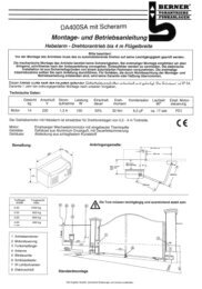
3 .2<br />
Montage der Zahnstange<br />
Vor der Montage:<br />
▶ Überprüfen Sie, ob die erforderliche Einschraubtiefe zur<br />
Verfügung steht.<br />
▶ Verwenden Sie zur Montage der Zahnstangen die<br />
Verbindungselemente (Schrauben und Muttern, etc.) aus<br />
dem Montagezubehör (siehe Bild C1 bzw. Bild C5,<br />
separat bestellen).<br />
HINWEIS:<br />
• Abweichend vom Bildteil müssen <strong>bei</strong> anderen torarten –<br />
auch hinsichtlich der Einschraublänge – die jeweils<br />
geeigneten Verbindungselemente benutzt werden (z.B.<br />
müssen <strong>bei</strong> holztoren entsprechende holzschrauben<br />
verwendet werden).<br />
• Abweichend vom Bildteil kann sich je nach Materialstärke<br />
oder Werkstofffestigkeit der notwendige<br />
Kernlochdurchmesser ändern. Der notwendige<br />
Durchmesser kann <strong>bei</strong> Alu Ø 5,0–5,5 mm und <strong>bei</strong> Stahl<br />
Ø 5,7–5,8 mm betragen.<br />
Montage:<br />
▶ Siehe Bild 4 – 4 .3<br />
ACHTUNG<br />
Beschädigung durch Schmutz<br />
Bei Bohrar<strong>bei</strong>ten können Bohrstaub und Späne zu<br />
Funktionsstörungen führen.<br />
▶ Decken Sie <strong>bei</strong> Bohrar<strong>bei</strong>ten den Antrieb ab.<br />
Der Schiebetorantrieb muss entriegelt sein (siehe Bild 3 .2).<br />
▶ Achten Sie <strong>bei</strong> der Montage auf versatzfreie Übergänge<br />
zwischen den einzelnen Zahnstangen, damit ein<br />
gleichmäßiger lauf des tores gewährleistet wird.<br />
▶ Sie müssen nach der Montage die Zahnstangen und das<br />
Zahnrad des Antriebs zueinander ausrichten. Dazu<br />
können sowohl die Zahnstangen als auch das<br />
Antriebsgehäuse justiert werden.<br />
Falsch montierte oder schlecht ausgerichtete<br />
Zahnstangen können zu unbeabsichtigtem<br />
Reversieren führen . Die vorgegebenen Maße müssen<br />
zwingend eingehalten werden!<br />
▶ Versiegeln Sie das Gehäuse gegen Feuchtigkeit und<br />
ungeziefer (siehe Bild 4 .4).<br />
3 .3 Anschluss der Netzzuleitung<br />
▶ Siehe Bild 4 .5<br />
Der netzanschluss erfolgt direkt an der Steckklemme am<br />
transformator mittels Erdkabel nYY. Da<strong>bei</strong> die<br />
Sicherheitshinweise aus Kapitel 2.5 beachten.<br />
3 .4 Montage des Platinenhalters<br />
▶ Siehe Bild 4 .6<br />
1 . Befestigen Sie den platinenhalter mit den zwei zuvor<br />
gelösten Schrauben D , sowie zwei weiteren aus dem<br />
lieferumfang.<br />
2 . Stecken Sie die Anschlussklemmen wieder auf.<br />
3 .5 Montage des Magnethalters<br />
▶ Siehe Bild 4 .7<br />
1 . Schieben sie das tor per hand in die Tor-Zu position.<br />
2 . Montieren Sie den Magnetschlitten in mittlerer position<br />
komplett vor.<br />
3 . Montieren sie die Zahnstangenklammer so, dass der<br />
Magnet um ca. 20 mm versetzt zu dem Reed-Kontakt im<br />
platinenhalter positioniert ist.<br />
3 .6 Verriegeln des Antriebes<br />
▶ Siehe Bild 5<br />
Durch das Verriegeln wird der Antrieb wieder eingekuppelt.<br />
▶ Drehen Sie den Mechanismus wieder in die<br />
Verriegelungsposition, der Motor muss da<strong>bei</strong> leicht<br />
angehoben werden.<br />
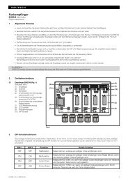
3 .7 Anschluss von Zusatzkomponenten/Zubehör<br />
▶ Siehe Übersicht der Steuerungsplatine in Bild 6<br />
ACHTUNG<br />
Zerstörung der Elektronik durch Fremdspannung<br />
Fremdspannung an den Anschlussklemmen der Steuerung<br />
führt zu einer Zerstörung der Elektronik.<br />
▶ legen Sie an den Anschlussklemmen der Steuerung<br />
keine netzspannung (230/240 V AC) an.<br />
10 V1.0_D_I / C300_C800 RE / 10.2009
Bei Anschluss von Zubehör an folgende Klemmen darf der<br />
entnommene Summenstrom max . 500 mA betragen:<br />
• 24 V=<br />
• SE3/lS<br />
• ext. Funk<br />
• SE1/SE2<br />
3 .7 .1 Anschluss eines externen Funk-Empfängers<br />
▶ Siehe Bild 6 .1<br />
▶<br />
Schließen Sie die Adern eines externen Funk-Empfängers<br />
wie folgt an:<br />
– Gn an die Klemme 20 (0 V)<br />
– Wh an die Klemme 21 (Signal Kanal 1)<br />
– Bn an die Klemme 5 (+24 V)<br />
– YE an die Klemme 23 (Signal für die teilöffnung<br />
Kanal 2). nur <strong>bei</strong> einem 2-Kanal-Empfänger.<br />
HINWEIS:<br />
Die Antennenlitze vom externen Funk-Empfänger sollte nicht<br />
mit Gegenständen aus Metall (nägel, Streben, usw.) in<br />
Verbindung kommen. Die beste Ausrichtung muss durch<br />
Versuche ermittelt werden.<br />
3 .7 .2 Anschluss eines externen Tasters*<br />
▶ Siehe Bild 6 .2<br />
(*Zubehör, ist nicht in der Standard-Ausstattung enthalten!)<br />
Ein oder mehrere taster mit Schließerkontakten (potentialfrei),<br />
z.B. Schlüsseltaster, können parallel angeschlossen werden,<br />
max. leitungslänge 10 m.<br />
Impulssteuerung:<br />
▶ Erster Kontakt an Klemme 21<br />
▶ Zweiter Kontakt an Klemme 20<br />
Teilöffnung:<br />
▶ Erster Kontakt an Klemme 23<br />
▶ Zweiter Kontakt an Klemme 20<br />
HINWEIS:<br />
Wird für einen externen taster eine hilfsspannung benötigt,<br />
steht dafür an Klemme 5 eine Spannung von +24 V DC (gegen<br />
Klemme 20 = 0 V) bereit.<br />
3 .7 .3 Anschluss eines Ausschalters zum Anhalten<br />
des Antriebs (Halt- bzw . Not-Aus-Kreis)<br />
Ein Ausschalter mit Öffnerkontakten (nach 0 V schaltend oder<br />
potentialfrei) wird wie folgt angeschlossen (siehe Bild 6 .3):<br />
1 . Entfernen Sie die werkseitig eingesetzte Drahtbrücke<br />
zwischen Klemme 12 und Klemme 13.<br />
– Klemme 12: halt- bzw. not-Aus-Eingang<br />
– Klemme 13: 0 V, ermöglicht eine normale Funktion<br />
des Antriebes<br />
2 . Schließen Sie den Schaltausgang oder ersten Kontakt an<br />
Klemme 12 (halt- bzw. not-Aus-Eingang) an.<br />
3 . Schließen Sie 0 V (Masse) oder den zweiten Kontakt an<br />
Klemme 13 (0 V) an.<br />
HINWEIS:<br />
Durch das Öffnen des Kontaktes werden eventuelle torfahrten<br />
sofort angehalten und dauerhaft unterbunden.<br />
3 .7 .4 Anschluss einer Warnleuchte*<br />
▶ Siehe Bild 6 .4<br />
(*Zubehör, ist nicht in der Standard-Ausstattung enthalten!)<br />
An den potentialfreien Kontakten am Stecker Option kann<br />
eine Warnleuchte oder die Endlagenmeldung Tor-Zu<br />
angeschlossen werden.<br />
Für den Betrieb (z.B. Warnmeldungen vor und während der<br />
torfahrt) mit einer 24 V lampe (max. 7 W) kann die Spannung<br />
am Stecker 24 V = herangezogen werden.<br />
HINWEIS:<br />
Eine 230 V-Warnleuchte muss direkt versorgt werden.<br />
3 .7 .5 Anschluss von Sicherheits-/<br />
Schutzeinrichtungen<br />
▶ Siehe Bild 6 .5 – 6 .7<br />
Es können Sicherheitseinrichtungen wie lichtschranken/<br />
Schließkantensicherungen (SKS) oder<br />
8k2-Widerstandskontaktleisten angeschlossen werden:<br />
SE1 in Richtung Öffnen, Sicherheitseinrichtung getestet<br />
oder Widerstandskontaktleiste 8k2<br />
SE2 in Richtung Schließen, Sicherheitseinrichtung<br />
getestet oder Widerstandskontaktleiste 8k2<br />
SE3 in Richtung Schließen, lichtschranke ohne testung<br />
oder dynamische 2-Draht-lichtschranke, z.B. als<br />
Durchfahrtslichtschranke<br />
Die Auswahl der Funktionen für die 3 Sicherheitskreise wird<br />
über DIl-Schalter eingestellt (siehe Kapitel 5).<br />
Klemmenbelegung:<br />
Klemme 20 0 V (Spannungsversorgung)<br />
Klemme 18 testsignal<br />
Klemmen 71/72/73 Signal der Sicherheitseinrichtung<br />
Klemme 5 +24 V (Spannungsversorgung)<br />
HINWEIS:<br />
Sicherheitseinrichtungen ohne testung (z.B. statische<br />
lichtschranken) müssen halbjährlich geprüft werden. Sie sind<br />
nur für den Sachschutz zulässig!<br />
3 .7 .6 Anschluss einer Universaladapterplatine UAP1*<br />
▶ Siehe Bild 6 .8<br />
(*Zubehör, ist nicht in der Standard-Ausstattung enthalten!)<br />
Anschlussmöglichkeit der universaladapterplatine uAp1.<br />
4<br />
▶<br />
▶<br />
Inbetriebnahme<br />
Überprüfen Sie vor der ersten Inbetriebnahme alle<br />
Anschlussleitungen auf die korrekte Installation an den<br />
Anschlussklemmen.<br />
Stellen Sie sicher, dass alle DIl-Schalter in der<br />
Werkseinstellung (OFF) stehen (siehe Bild 7), das tor halb<br />
geöffnet und der Antrieb eingekuppelt ist.<br />
4 .1 Vorbereitung<br />
Stellen Sie folgende DIL-Schalter um:<br />
▶ DIL-Schalter 1: Einbaurichtung (siehe Bild 7 .1)<br />
– Auf On, wenn das tor nach rechts schließt.<br />
– Auf OFF, wenn das tor nach links schließt.<br />
DEUTSCH<br />
V1.0_D_I / C300_C800 RE / 10.2009 11
DEUTSCH<br />
▶ DIL-Schalter 3-7: Sicherheitseinrichtungen (siehe<br />
Bild 9 .6/9 .7/9 .8)<br />
– Entsprechend der angeschlossenen Sicherheits- und<br />
Schutzeinrichtungen einstellen (siehe Kapitel 5.3 –<br />
5.5). Sind während des Einrichtbetriebes allerdings<br />
nicht aktiv.<br />
4 .2 Einlernen der Torendlagen<br />
4 .2 .1 Endlagenerfassung Tor-Zu<br />
▶ Siehe Bild 8 .1a<br />
Vor dem Einlernen der Endlagen muss der Endschalter (Reed-<br />
Kontakt) angeschlossen sein. Die Adern des Endschalters<br />
müssen an der Klemme REED angeklemmt sein.<br />
Das Optionsrelais hat <strong>bei</strong>m Einrichten die gleiche Funktion<br />
wie die rote lED. Mit einer hier angeschlossenen lampe lässt<br />
sich die Endschalterstellung aus der Ferne beobachten (siehe<br />
Bild 6 .4).<br />
Einlernen der Endlage Tor-Zu:<br />
1 . Öffnen Sie das tor halb.<br />
2 . Stellen sie DIL-Schalter 2 (Einrichtbetrieb) auf ON.<br />
Die grüne lED blinkt langsam, die rote lED leuchtet<br />
konstant.<br />
3 . Drücken Sie den platinentaster T und halten ihn<br />
gedrückt.<br />
Das tor fährt in Schleichfahrt in Richtung Tor-Zu. Bei<br />
Erreichen des Endschalters erlischt die rote lED.<br />
4 . lassen Sie den platinentaster T unverzüglich los.<br />
Das tor befindet sich nun in der Endlage Tor-Zu.<br />
HINWEIS:<br />
Fährt das tor in Richtung Auf, befindet sich der<br />
DIL-Schalter 1 in der falschen position und muss umgestellt<br />
werden. Anschließend die Schritte 1 bis 4 wiederholen.<br />
Falls diese position des geschlossenen tores nicht der<br />
gewünschten Endlage Tor-Zu entspricht, muss nachjustiert<br />
werden.<br />
Endlage Tor-Zu nachjustieren:<br />
1 . Verändern Sie die position des Magneten durch<br />
Verschieben des Magnetschlittens.<br />
2 . Drücken Sie den platinentaster T, um der so verstellten<br />
Endlage zu folgen, bis die rote lED wieder erlischt.<br />
3 . Wiederholen Sie die Schritte 1 . + 2 . so lange, bis die<br />
gewünschte Endlage erreicht ist.<br />
4 .2 .2 Endlagenerfassung Tor-Auf<br />
▶ Siehe Bild 8 .1b<br />
Einlernen der Endlage Tor-Auf:<br />
4 . Drücken Sie den platinentaster T und halten ihn<br />
gedrückt.<br />
Das tor fährt in Schleichfahrt in Richtung Tor-Auf.<br />
5 . lassen Sie den platinentaster T los, wenn die<br />
gewünschte Endlage Tor-Auf erreicht.<br />
6 . Drücken Sie den platinentaster P, um diese position zu<br />
bestätigen.<br />
Die grüne lED signalisiert durch ein 2 Sekunden langes,<br />
sehr schnelles Blinken das Erfassen der Endlage Tor-Auf.<br />
4 .2 .3 Endlagenerfassung Teilöffnung<br />
▶ Siehe Bild 8 .1c<br />
HINWEIS:<br />
Ist ein totmannbetrieb eingestellt, ist die Endlagenerfassung<br />
Teilöffnung nicht möglich.<br />
Einlernen der Endlage Teilöffnung:<br />
1 . Drücken Sie den platinentaster T und halten ihn<br />
gedrückt, um das tor in Richtung Tor-Zu zu fahren.<br />
2 . lassen Sie den platinentaster T los, wenn die<br />
gewünschte Endlage Teilöffnung erreicht ist.<br />
3 . Drücken Sie den platinentaster P, um diese position zu<br />
bestätigen.<br />
Die grüne lED signalisiert durch langsames Blinken das<br />
Erfassen der Endlage Teilöffnung.<br />
4 .2 .4 Abschluss des Einrichtbetriebes<br />
▶ Stellen Sie nach Abschluss des Einlernvorgangs<br />
DIL-Schalter 2 wieder auf OFF.<br />
Die grüne lED signalisiert durch schnelles Blinken, dass<br />
Kraftlernfahrten durchgeführt werden müssen.<br />
Die Sicherheitseinrichtungen sind wieder aktiv.<br />
4 .2 .5 Referenzfahrt<br />
▶ Siehe Bild 8 .2<br />
nach dem Einlernen der Endlagen ist die erste Fahrt immer<br />
eine Referenzfahrt. Während der Referenzfahrt wird das<br />
Optionsrelais getaktet und eine angeschlossene Warnleuchte<br />
blinkt.<br />
Referenzfahrt bis Endlage Tor-Zu:<br />
▶ Drücken Sie den platinentaster T einmal.<br />
Der Antrieb fährt selbständig bis in die Endlage Tor-Zu.<br />
▶ Ist ein totmannbetrieb eingestellt, drücken Sie den<br />
platinentaster T und halten ihn bis in die Endlage Tor-Zu<br />
gedrückt.<br />
HINWEIS:<br />
Ist ein totmannbetrieb eingestellt (DIL-Schalter 16 auf ON) ist<br />
die Inbetriebnahme hier beendet.<br />
4 .3 Kräfte lernen<br />
nach dem Einlernen der Endlagen und der Referenzfahrt<br />
müssen Kraftlernfahrten durchgeführt werden. hierfür sind<br />
drei ununterbrochene tor-Zyklen erforderlich, <strong>bei</strong> denen keine<br />
Sicherheitseinrichtung ansprechen darf. Die Erfassung der<br />
Kräfte erfolgt in <strong>bei</strong>de Richtungen automatisch im<br />
Selbsthaltebetrieb. Während des gesamten lernvorgangs<br />
blinkt die grüne lED. nach Abschluss der Kraftlernfahrten<br />
leuchtet diese dann konstant (siehe Bild 9 .1).<br />
▶ Die <strong>bei</strong>den folgenden Vorgänge müssen dreimal<br />
durchgeführt werden .<br />
Kraftlernfahrten:<br />
▶ Drücken Sie den platinentaster T einmal.<br />
Der Antrieb fährt selbständig bis in die Endlage Tor-Auf.<br />
▶ Drücken Sie den platinentaster T einmal.<br />
Der Antrieb fährt selbständig bis in die Endlage Tor-Zu.<br />
4 .3 .1<br />
Kraftbegrenzung einstellen<br />
WARNUNG<br />
Verletzungsgefahr <strong>bei</strong> zu hoher Kraftbegrenzung<br />
Bei einer zu hoch eingestellten Kraftbegrenzung stoppt das<br />
tor <strong>bei</strong>m Schließen nicht rechtzeitig und kann da<strong>bei</strong><br />
personen oder Gegenstände einklemmen.<br />
▶ Stellen Sie keine zu hohe Kraftbegrenzung ein.<br />
12 V1.0_D_I / C300_C800 RE / 10.2009
HINWEIS:<br />
Aufgrund besonderer Einbausituationen kann es vorkommen,<br />
dass die zuvor gelernten Kräfte nicht ausreichen, was zu<br />
ungewollten Reversiervorgängen führen kann. In solchen<br />
Fällen kann die Kraftbegrenzung nachgestellt werden.<br />
Die Kraftbegrenzung der toranlage wird durch ein<br />
potentiometer eingestellt, das auf der Steuerungsplatine mit<br />
Kraft F beschriftet ist (siehe Bild 9 .1).<br />
1 . Die Erhöhung der Kraftbegrenzung erfolgt prozentual zu<br />
den gelernten Werten, da<strong>bei</strong> bedeutet die Stellung des<br />
potentiometers die folgende Kraft-Zunahme:<br />
Linksanschlag + 0 % Kraft<br />
Mittelstellung +15 % Kraft<br />
Rechtsanschlag +75 % Kraft<br />
2 . Die eingelernte Kraft mittels einer geeigneten<br />
Kraftmesseinrichtung auf zulässige Werte im<br />
Geltungsbereich der En 12453 und En 12445 oder den<br />
entsprechenden nationalen Vorschriften prüfen.<br />
4 .3 .2 Antriebsgeschwindigkeit<br />
Sollte die mittels Kraftmesseinrichtung gemessene Kraft <strong>bei</strong><br />
Stellung des potentiometers am linksanschlag noch zu hoch<br />
sein, kann dieses über eine verringerte Verfahrgeschwindigkeit<br />
geändert werden. (siehe Bild 9 .2)<br />
Geschwindigkeit einstellen:<br />
1 . Stellen Sie den DIL-Schalter 15 auf ON.<br />
2 . Führen Sie drei aufeinander folgende Kraftlernfahrten<br />
durch (siehe Kapitel 4.3).<br />
3 . Führen Sie eine erneute prüfung mittels<br />
Kraftmesseinrichtung durch.<br />
4 .3 .3<br />
Kraftbegrenzung ausschalten<br />
HINWEIS<br />
Nicht für den Einsatz in Ländern mit EU-Richtlinien!<br />
Durch das Durchkneifen der Drahtbrücke BR1 auf der<br />
Steuerungsplatine kann die Kraftbegrenzung ausgeschaltet<br />
werden.<br />
Sind keine Sicherheitseinrichtungen angeschlossen (DIL-<br />
Schalter 3 – 6 auf OFF) fährt der Antrieb ausschließlich im<br />
totmannbetrieb.<br />
Sind Widerstandskontaktleisten 8k2 angeschlossen<br />
(DIL-Schalter 3 – 6 auf ON) fährt der Antrieb in Selbsthaltung<br />
ohne Kraftbegrenzung.<br />
Kraftbegrenzung deaktivieren:<br />
1 . Führen Sie ein Werksreset durch ( siehe Kapitel 10).<br />
2 . Kneifen Sie die Drahtbrücke BR1 durch.<br />
3 . Stellen Sie den DIL-Schalter 2 auf ON und lernen Sie<br />
den Antrieb neu ein (siehe Kapitel 4.2).<br />
Wird die Drahtbrücke nach dem Einrichten oder während<br />
einer torfahrt durchgekniffen hat es keine Auswirkung auf die<br />
Funktion.<br />
Kraftbegrenzung wieder aktivieren:<br />
1 . Führen Sie ein Werksreset durch ( siehe Kapitel 10).<br />
2 . Verbinden Sie die Drahtbrücke BR1.<br />
3 . Stellen Sie den DIL-Schalter 2 auf ON und lernen Sie<br />
den Antrieb neu ein (siehe Kapitel 4.2).<br />
4 .4 Startpunkte für Schleichfahrt <strong>bei</strong>m Öffnen und<br />
Schließen ändern<br />
Die länge der Schleichfahrt wird nach dem Einlernen der<br />
Endlagen automatisch auf einen Grundwert von ca. 500 mm<br />
vor den Endlagen gesetzt. Die Startpunkte können auf eine<br />
länge von minimal ca. 300 mm bis zur gesamten torlänge<br />
umprogrammiert werden (siehe Bild 9 .3).<br />
Das Ändern der Startpunkte für Schleichfahrt hat zur Folge,<br />
dass die bereits eingelernten Kräfte gelöscht werden und<br />
nach Abschluss der Änderung erneut eingelernt werden<br />
müssen.<br />
Einrichten der Positionen – Schleichfahrt:<br />
1 . Die Endlagen müssen eingerichtet sein, das tor muss<br />
sich in Endlage Tor-Zu befinden und der DIL-Schalter 2<br />
muss auf OFF stehen.<br />
2 . Stellen Sie den DIL-Schalter 12 auf ON.<br />
3 . Drücken Sie den platinentaster T.<br />
Der Antrieb fährt in normalfahrt mit Selbsthaltung in<br />
Richtung Tor-Auf.<br />
4 . passiert das tor die gewünschte position für den Beginn<br />
der Schleichfahrt, drücken Sie kurz den platinentaster P.<br />
Der Antrieb fährt die restliche Strecke zur Endlage<br />
Tor-Auf in Schleichfahrt.<br />
5 . Drücken Sie den platinentaster T nochmals.<br />
Der Antrieb fährt wieder in normalfahrt mit Selbsthaltung<br />
in Richtung Tor-Zu.<br />
6 . passiert das tor die gewünschte position für den Beginn<br />
der Schleichfahrt, drücken Sie kurz den platinentaster P.<br />
Der Antrieb fährt die restliche Strecke zur Endlage Tor-Zu<br />
in Schleichfahrt.<br />
7 . Stellen Sie den DIL-Schalter 12 auf OFF.<br />
Das Einstellen der Startpunkte für Schleichfahrt ist<br />
abgeschlossen. Das Blinken der grünen lED signalisiert, dass<br />
erneut Kraftlernfahrten durchgeführt werden müssen.<br />
HINWEIS:<br />
Die Startpunkte der Schleichfahrt können auch überlappend<br />
eingestellt werden; in diesem Fall wird die ganze<br />
torbewegung in Schleichfahrt durchgeführt.<br />
4 .5 Reversiergrenze<br />
Beim Betrieb der toranlage muss <strong>bei</strong> der Fahrt in Richtung<br />
Tor-Zu unterschieden werden, ob das tor gegen den<br />
Endanschlag (toranlage stoppt) oder gegen ein hindernis (tor<br />
verfährt in Gegenrichtung) läuft. Der Grenzbereich lässt sich<br />
wie folgt verändern (siehe Bild 9 .4).<br />
Reversiergrenze einstellen:<br />
1 . Stellen Sie den DIL-Schalter 11 auf ON.<br />
Die Reversiergrenze kann nun stufig eingestellt werden.<br />
2 . Drücken Sie den platinentaster P kurz, um die<br />
Reversiergrenze zu verringern.<br />
Drücken Sie den platinentaster T kurz, um die<br />
Reversiergrenze zu vergrößern.<br />
Beim Einstellen zeigt die grüne lED folgende<br />
Einstellungen an:<br />
1x blinken<br />
bis<br />
DEUTSCH<br />
minimale Reversiergrenze, die grüne<br />
lED blinkt einmal<br />
10x blinken maximale Reversiergrenze, die grüne<br />
lED blinkt 10 mal<br />
3 . Stellen Sie den DIL-Schalter 11 wieder auf OFF, um die<br />
eingestellte Reversiergrenze zu speichern.<br />
V1.0_D_I / C300_C800 RE / 10.2009 13
DEUTSCH<br />
4 .6<br />
Automatischer Zulauf<br />
HINWEIS<br />
Der automatische Zulauf kann nur aktiviert werden, wenn<br />
mindestens eine Sicherheitseinrichtung aktiviert ist.<br />
Beim Betrieb mit automatischem Zulauf kann die Aufhaltezeit<br />
eingestellt werden (siehe Bild 9 .5).<br />
Aufhaltezeit einstellen:<br />
1 . Stellen sie den DIL-Schalter 13 auf ON.<br />
Die Aufhaltezeit kann nun stufig eingestellt werden.<br />
2 . Drücken Sie den platinentaster P kurz, um die<br />
Aufhaltezeit zu verringern.<br />
Drücken Sie den platinentaster T kurz, um die<br />
Aufhaltezeit zu vergrößern.<br />
Beim Einstellen zeigt die grüne lED folgende<br />
Einstellungen an:<br />
1x blinken 30 Sekunden Aufhaltezeit<br />
2x blinken 60 Sekunden Aufhaltezeit<br />
3x blinken 90 Sekunden Aufhaltezeit<br />
4x blinken 120 Sekunden Aufhaltezeit<br />
5x blinken 180 Sekunden Aufhaltezeit<br />
3 . Stellen Sie den DIL-Schalter 13 wieder auf OFF, um die<br />
eingestellte Aufhaltezeit zu speichern.<br />
5<br />
Funktionen der DIL-Schalter<br />
Die Steuerung wird mittels DIl-Schalter programmiert. Vor der<br />
ersten Inbetriebnahme befinden sich die DIl-Schalter in<br />
Werkseinstellung, d.h. alle Schalter stehen auf OFF.<br />
Änderungen der DIl-Schalter-Einstellungen sind nur unter<br />
folgenden Voraussetzungen zulässig:<br />
• Der Antrieb ruht.<br />
• Es ist keine Vorwarn- oder Aufhaltezeit aktiv.<br />
Entsprechend der nationalen Vorschriften, den gewünschten<br />
Sicherheitseinrichtungen und den örtlichen Gegebenheiten<br />
müssen die DIl-Schalter wie in den folgenden Abschnitten<br />
beschrieben eingestellt werden.<br />
5 .1<br />
DIL-Schalter 1<br />
Einbaurichtung:<br />
▶ Siehe Bild 7 .1<br />
1 ON tor schließt nach rechts (vom Antrieb aus<br />
gesehen)<br />
1 OFF tor schließt nach links (vom Antrieb aus gesehen)<br />
5 .2<br />
DIL-Schalter 2<br />
Einrichtbetrieb:<br />
▶ Siehe Bild 8 .1a – c<br />
Im Einrichtbetrieb sind die Sicherheits- und<br />
Schutzeinrichtungen nicht aktiv.<br />
2 ON • Verfahrweg einlernen<br />
• tordaten löschen<br />
2 OFF normalbetrieb<br />
5 .3 DIL-Schalter 3 / DIL-Schalter 4<br />
Sicherheitseinrichtung SE 1 (Öffnen):<br />
▶ Siehe Bild 9 .6<br />
Mit DIL-Schalter 3 in Kombination mit DIL-Schalter 4<br />
werden Art und Wirkung der SE 1 eingestellt.<br />
3 ON Anschlusseinheit Schließkantensicherung oder<br />
lichtschranke mit testung<br />
3 OFF • Widerstandskontaktleiste 8k2<br />
• lichtschranke anderer hersteller<br />
• keine Sicherheitseinrichtung (Widerstand 8k2<br />
zwischen Klemme 20/72,<br />
Auslieferungszustand)<br />
4 ON sofortiges kurzes Reversieren in Richtung tor-Zu<br />
(für SKS)<br />
4 OFF verzögertes kurzes Reversieren in Richtung tor-Zu<br />
(für lichtschranke)<br />
5 .4<br />
DIL-Schalter 5 / DIL-Schalter 6<br />
Sicherheitseinrichtung SE 2 (Schließen):<br />
▶ Siehe Bild 9 .7<br />
Mit DIL-Schalter 5 in Kombination mit DIL-Schalter 6<br />
werden Art und Wirkung der SE 2 eingestellt.<br />
5 ON Anschlusseinheit Schließkantensicherung oder<br />
lichtschranke mit testung<br />
5 OFF • Widerstandskontaktleiste 8k2<br />
• lichtschranke anderer hersteller<br />
• keine Sicherheitseinrichtung (Widerstand 8k2<br />
zwischen Klemme 20/73,<br />
Auslieferungszustand)<br />
6 ON sofortiges kurzes Reversieren in Richtung tor-Auf<br />
(für SKS)<br />
6 OFF verzögertes kurzes Reversieren in Richtung<br />
tor-Auf (für lichtschranke)<br />
5 .5 DIL-Schalter 7<br />
Schutzeinrichtung SE 3 (Schließen):<br />
▶ Siehe Bild 9 .8<br />
Verzögertes Reversieren bis in Endlage Tor-Auf.<br />
7 ON Dynamische 2-Draht-lichtschranke<br />
7 OFF • ungetestete statische lichtschranke<br />
• keine Sicherheitseinrichtung (Drahtbrücke<br />
zwischen Klemme 20/71,<br />
Auslieferungszustand)<br />
14 V1.0_D_I / C300_C800 RE / 10.2009
5 .6 DIL-Schalter 8 / DIL-Schalter 9<br />
Mit DIL-Schalter 8 in Kombination mit DIL-Schalter 9<br />
werden die Funktionen des Antriebs (automatischer Zulauf /<br />
Vorwarnzeit) und des Optionsrelais eingestellt.<br />
▶ Siehe Bild 9 .9a<br />
8 ON 9 ON Antrieb<br />
automatischer Zulauf, Vorwarnzeit <strong>bei</strong><br />
jeder torfahrt<br />
▶ Siehe Bild 9 .9b<br />
Optionsrelais<br />
Das Relais taktet <strong>bei</strong> der Vorwarnzeit<br />
schnell, während der torfahrt normal und<br />
<strong>bei</strong> der Aufhaltezeit ist es aus.<br />
8 OFF 9 ON Antrieb<br />
automatischer Zulauf, Vorwarnzeit nur<br />
<strong>bei</strong> automatischem Zulauf<br />
Optionsrelais<br />
Das Relais taktet <strong>bei</strong> der Vorwarnzeit<br />
schnell, während der torfahrt normal<br />
und <strong>bei</strong> der Aufhaltezeit ist es aus.<br />
▶ Siehe Bild 9 .9c<br />
8 ON 9 OFF Antrieb<br />
Vorwarnzeit <strong>bei</strong> jeder torfahrt ohne<br />
automatischen Zulauf<br />
Optionsrelais<br />
Das Relais taktet <strong>bei</strong> der Vorwarnzeit<br />
schnell, während der torfahrt normal.<br />
▶ Siehe Bild 9 .9d<br />
8 OFF 9 OFF Antrieb<br />
Ohne besondere Funktion<br />
Optionsrelais<br />
Das Relais zieht in der Endlage Tor-Zu<br />
an.<br />
HINWEIS:<br />
Ein automatischer Zulauf ist immer nur aus den festgelegten<br />
Endlagen (Voll- oder teilöffnung) möglich. Ist ein<br />
automatischer Zulauf dreimal fehlgeschlagen, wird er<br />
deaktiviert. Der Antrieb muss mit einem Impuls neu gestartet<br />
werden.<br />
5 .7<br />
DIL-Schalter 10<br />
Wirkung der Schutzeinrichtung SE3 als<br />
Durchfahrtslichtschranke <strong>bei</strong> automatischem Zulauf<br />
▶ Siehe Bild 9 .10<br />
10 ON Die lichtschranke ist als<br />
Durchfahrtslichtschranke aktiviert, nach<br />
Durchfahrt oder Durchgang der lichtschranke<br />
wird die Aufhaltezeit verkürzt.<br />
10 OFF Die lichtschranke ist nicht als<br />
Durchfahrtslichtschranke aktiviert. Ist aber<br />
automatischer Zulauf aktiviert und ist nach<br />
Ablauf der Aufhaltezeit die lichtschranke<br />
unterbrochen, wird die Aufhaltezeit wieder auf<br />
die voreingestellte Zeit gesetzt.<br />
5 .8<br />
DIL-Schalter 11<br />
Einstellen der Reversiergrenzen:<br />
▶ Siehe Bild 9 .4 und Kapitel 4.5<br />
11 ON Reversiergrenze wird stufig eingestellt<br />
11 OFF normalbetrieb<br />
5 .9<br />
DIL-Schalter 12<br />
Startpunkt der Schleichfahrt <strong>bei</strong>m Öffnen und Schließen:<br />
▶ Siehe Bild 9 .3 und Kapitel 4.4<br />
12 ON Schleichfahrt-Startpunkte werden <strong>bei</strong>m Öffnen<br />
und Schließen eingerichtet<br />
12 OFF normalbetrieb<br />
5 .10<br />
DIL-Schalter 13<br />
Einstellen der Aufhaltezeit:<br />
▶ Siehe Bild 9 .5 und Kapitel 4.6<br />
13 ON Aufhaltezeit wird stufig eingestellt<br />
13 OFF normalbetrieb<br />
5 .11<br />
DIL-Schalter 14<br />
Impulsverhalten während der Aufhaltezeit:<br />
Beim Betrieb mit automatischem Zulauf kann das<br />
Impulsverhalten während der Aufhaltezeit eingestellt werden.<br />
14 ON Ein Impuls bricht die Aufhaltezeit ab. Der Antrieb<br />
fährt das tor nach Ablauf der Vorwarnzeit zu.<br />
14 OFF Ein Impuls verlängert die Aufhaltezeit um die<br />
voreingestellte Zeit.<br />
5 .12<br />
DIL-Schalter 15<br />
Einstellen der Geschwindigkeit:<br />
▶ Siehe Bild 9 .2 und Kapitel 4.3.2<br />
15 ON langsamer Betrieb (langsame Geschwindigkeit);<br />
(keine SKS erforderlich)<br />
15 OFF normaler Betrieb (normale Geschwindigkeit)<br />
DEUTSCH<br />
V1.0_D_I / C300_C800 RE / 10.2009 15
DEUTSCH<br />
5 .13<br />
DIL-Schalter 16<br />
Einstellen der Betriebsart:<br />
Mit DIL-Schalter 16 kann ein totmannbetrieb eingestellt<br />
werden. Die Kraftbegrenzung ist auf den maximalen Wert<br />
eingestellt.<br />
16 ON totmannbetrieb<br />
•<br />
•<br />
•<br />
16 OFF normalbetrieb<br />
Ein Dauerkontakt an den Klemmen 20 + 21<br />
verfährt der Antrieb in Richtung Tor-Auf<br />
Ein Dauerkontakt an den Klemmen 20 + 23<br />
verfährt der Antrieb in Richtung Tor-Zu<br />
Wird jeweils der Kontakt unterbrochen,<br />
stoppt der Antrieb<br />
HINWEIS:<br />
Im totmannbetrieb sind in Verbindung mit einer<br />
universaladapterplatine uAp 1 Sonderfunktionen möglich.<br />
6<br />
Funk<br />
VORSICHT<br />
Unbeabsichtigte Torfahrt<br />
Während des lernvorgangs am Funk-System kann es zu<br />
ungewollten torfahrten kommen.<br />
▶ Achten Sie darauf, dass sich <strong>bei</strong>m Einlernen des Funk-<br />
Systems keine personen oder Gegenstände im<br />
Bewegungsbereich des tores befinden.<br />
•<br />
•<br />
6 .1<br />
Führen Sie nach dem Einlernen oder Erweitern des Funk-<br />
Systems eine Funktionsprüfung durch.<br />
Verwenden Sie für die Erweiterung des Funk-Systems<br />
ausschließlich Originalteile.<br />
Handsender<br />
6 .1 .1 Bedienelemente<br />
▶ Siehe Bild 10<br />
1 lED<br />
2 handsendertasten<br />
3 Batteriefachdeckel<br />
4 Batterie<br />
5 Reset-taster<br />
6 handsenderhalterung<br />
6 .1 .2<br />
Wichtige Hinweise zum Gebrauch des<br />
Handsenders<br />
WARNUNG<br />
Verletzungsgefahr <strong>bei</strong> Torbewegung<br />
Wird der handsender bedient, können personen durch die<br />
torbewegung verletzt werden.<br />
▶ Stellen Sie sicher, dass handsender nicht in<br />
Kinderhände gelangen und nur von personen benutzt<br />
werden, die in die Funktionsweise der ferngesteuerten<br />
toranlage eingewiesen sind.<br />
▶ Bedienen Sie den handsender generell mit<br />
Sichtkontakt zum tor, wenn dieses nur über eine<br />
Sicherheitseinrichtung verfügt!<br />
ACHTUNG<br />
Beeinträchtigung der Funktion durch Umwlteinflüsse<br />
Bei nichtbeachtung kann die Funktion beeinträchtigt<br />
werden!<br />
▶ Schützen Sie den handsender vor folgenden<br />
umwelteinflüssen:<br />
– Feuchtigkeit<br />
– Staubbelastung<br />
– direkte Sonneneinstrahlung (zul.<br />
umgebungstemperatur: –20° C bis +60° C)<br />
HINWEIS:<br />
Die örtlichen Gegebenheiten können Einfluss auf die<br />
Reichweite des Funk-Systems haben. Außerdem können<br />
GSM-900-handys <strong>bei</strong> gleichzeitiger Benutzung die<br />
Reichweite beeinflussen.<br />
6 .1 .3 Batterie einlegen/wechseln<br />
▶ Siehe Bild 10<br />
6 .1 .4 LED-Signale des Handsenders<br />
• Die LED leuchtet auf:<br />
Der handsender sendet einen Funkcode.<br />
• Die LED blinkt:<br />
Der handsender sendet zwar noch, die Batterie ist<br />
jedoch so entladen, dass sie kurzfristig ausgetauscht<br />
werden sollte.<br />
• Die LED zeigt keine Reaktion:<br />
Der handsender funktioniert nicht.<br />
– prüfen Sie, ob die Batterie richtig herum eingesetzt<br />
ist.<br />
– tauschen Sie die Batterie gegen eine neuwertige aus.<br />
6 .2<br />
Funk-Empfänger<br />
6 .2 .1 Externer Funkempfänger<br />
Der Stecker des Empfängers wird auf den entsprechenden<br />
Steckplatz gesteckt (siehe Bild 6 .1). Auf dem externen Funk-<br />
Empfänger kann die Funktion Impuls (Auf – Stopp – Zu –<br />
Stopp) und die Funktion Teilöffnung für je max. 50<br />
verschiedene handsender eingelernt werden. Werden mehr<br />
als je 50 handsender eingelernt, so werden die zuerst<br />
eingelernten gelöscht.<br />
6 .3<br />
Einlernen der Handsendertasten in den<br />
externen Empfänger<br />
6 .3 .1 Eine Tastenfunktion für Kanal 1 (Impuls-Befehl)<br />
zuweisen<br />
1 . Die P-taste (programmiertaster) des Empfängers kurz<br />
drücken. Die lED beginnt zu leuchten.<br />
2 . Die gewünschte taste am handsender mindestens 3<br />
Sek. drücken, bis die lED erlischt.<br />
3 . Die taste wieder loslassen.<br />
4 . Der Empfänger ist empfangsbereit<br />
Der Code dieser handsender-taste ist nun im Empfänger<br />
gespeichert (siehe Bild 11a).<br />
6 .3 .2 Eine Tastenfunktion für Kanal 2 (Teilöffnungs-<br />
Befehl) zuweisen<br />
1 . Die P-taste (programmiertaster) des Empfängers kurz<br />
drücken. Die lED leuchtet.<br />
2 . Die P-taste nochmals drücken. Die lED erlischt kurz und<br />
leuchtet anschließend wieder.<br />
16 V1.0_D_I / C300_C800 RE / 10.2009
3 . Die gewünschte taste am handsender mindestens<br />
3 Sek. drücken, bis die lED erlischt.<br />
4 . Die taste wieder loslassen.<br />
5 . Der Empfänger ist empfangsbereit.<br />
Der Code dieser handsender-taste ist nun im Empfänger<br />
gespeichert (siehe Bild 11b).<br />
6 .4 Betrieb<br />
Zum Betrieb des Schiebetorantriebs mit Funk muss<br />
mindestens eine handsendertaste an dem externen<br />
Empfänger eingelernt sein.<br />
Bei der Funkübertragung sollte der Abstand zwischen<br />
handsender und Empfänger mindestens 1 m betragen.<br />
6 .5 Löschen der Daten eines externen<br />
Funkempfängers<br />
1 . Die P-taste des Empfängers drücken und für ca. 10 Sek.<br />
gedrückt halten. Die lED blinkt.<br />
2 . Den Blinkvorgang abwarten und die taste wieder loslassen.<br />
Alle eingelernten handsender sind nun gelöscht.<br />
HINWEIS:<br />
Das löschen einzelner handsender ist nicht möglich.<br />
7<br />
Betrieb<br />
WARNUNG<br />
Quetsch- und Schergefahr<br />
Bei der torfahrt können Finger oder Gliedmaßen von der<br />
Zahnstange sowie zwischen tor und Schließkante<br />
eingequetscht oder abgetrennt werden.<br />
▶ Greifen Sie während einer torfahrt nicht mit den<br />
Fingern an die Zahnstange, das Zahnrad und die<br />
haupt- und nebenschließkanten.<br />
WARNUNG<br />
Verletzungsgefahr <strong>bei</strong> Torbewegung<br />
Beim Schließen des tores können personen<br />
oder Gegenstände eingeklemmt werden.<br />
▶ Stellen Sie sicher, dass sich im<br />
Bewegungsbereich des tores keine<br />
personen oder Gegenstände befinden.<br />
▶ Stellen Sie sicher, dass keine Kinder an<br />
der toranlage spielen.<br />
▶ Betreiben Sie den Schiebetorantrieb nur,<br />
wenn Sie den Bewegungsbereich des<br />
tores einsehen können, sofern dieses nur<br />
über eine Sicherheitseinrichtung.<br />
▶ Vergewissern Sie sich vor der Ein- bzw.<br />
Ausfahrt, ob das tor auch ganz geöffnet<br />
wurde. Ferngesteuerte toranlagen dürfen<br />
erst durchfahren bzw. durchgangen<br />
werden, wenn das tor zum Stillstand<br />
gekommen ist.<br />
7 .1 Benutzer einweisen<br />
▶ Weisen Sie alle personen, die die toranlage benutzen, in<br />
die ordnungsgemäße und sichere Bedienung ein.<br />
▶ Demonstrieren und testen Sie die mechanische<br />
Entriegelung sowie den Sicherheitsrücklauf.<br />
7 .2<br />
▶<br />
Funktionsprüfung<br />
▶<br />
DEUTSCH<br />
um den Sicherheitsrücklauf zu<br />
prüfen, halten Sie das tor während<br />
es zufährt mit <strong>bei</strong>den händen an.<br />
Die toranlage muss anhalten und<br />
den Sicherheitsrücklauf einleiten.<br />
Ebenso muss während das tor<br />
auffährt die toranlage abschalten<br />
und das tor stoppen.<br />
Beauftragen Sie <strong>bei</strong> Versagen des Sicherheitsrücklaufs<br />
unmittelbar einen Sachkundigen mit der prüfung bzw. der<br />
Reparatur.<br />
7 .3 Normaler Fahrbetrieb:<br />
Der Schiebetorantrieb ar<strong>bei</strong>tet im normalen Fahrbetrieb<br />
ausschließlich entsprechend der Impulsfolgesteuerung (Auf–<br />
Stopp–Zu–Stopp), wo<strong>bei</strong> unerheblich ist, ob ein externer<br />
taster, eine handsendertaste oder der platinentaster T<br />
betätigt wurde:<br />
▶ Drücken Sie zum Öffnen und Schließen in Vollöffnung<br />
den entsprechenden Impulsgeber für Kanal 1.<br />
▶ Drücken Sie zum Öffnen und Schließen in teilöffnung den<br />
entsprechenden Impulsgeber für Kanal 2.<br />
7 .4 Verhalten <strong>bei</strong> einem Spannungsausfall<br />
um das Schiebetor während eines Spannungsausfalls von<br />
hand öffnen oder schließen zu können, muss es vom Antrieb<br />
entkuppelt werden.<br />
ACHTUNG!<br />
Beschädigung durch Feuchtigkeit<br />
▶ Schützen Sie <strong>bei</strong>m Öffnen des Antriebsgehäuses die<br />
Steuerung vor Feuchtigkeit.<br />
1 . Öffnen Sie den Gehäusedeckel entsprechend Bild 3 .1.<br />
2 . Entriegeln Sie den Antrieb durch Drehen des<br />
Verriegelungsmechanismus.<br />
Gegebenenfalls müssen der Motor und das Zahnrad von<br />
hand heruntergedrückt werden (siehe Bild 13 .1).<br />
7 .5 Verhalten nach einem Spannungsausfall<br />
nach Spannungsrückkehr muss das tor vor dem<br />
Endlagenschalter wieder an den Antrieb gekuppelt werden.<br />
▶ heben Sie <strong>bei</strong>m Verriegeln den Motor leicht an (siehe<br />
Bild 13 .2).<br />
nach einem Spannungsausfall ist eine erneute Referenzfahrt<br />
notwendig. Diese wird automatisch <strong>bei</strong> einem anstehenden<br />
Impuls-Befehl ausgeführt.<br />
8 Prüfung und Wartung<br />
Der Schiebetorantrieb ist wartungsfrei. Zu Ihrer eigenen<br />
Sicherheit empfehlen wir jedoch, die Toranlage nach<br />
Herstellerangaben durch einen Sachkundigen überprüfen<br />
zu lassen.<br />
Eine prüfung oder notwendige Reparatur darf nur von einer<br />
sachkundigen person durchgeführt werden. Wenden Sie sich<br />
hierzu an Ihren lieferanten. Eine optische prüfung kann vom<br />
Betreiber durchgeführt werden.<br />
▶ Alle Sicherheits- und Schutzfunktionen monatlich,<br />
▶ Widerstandskontatleisten 8k2 halbjährlich auf ihre<br />
Funktion prüfen.<br />
▶ Falls erforderlich vorhandene Fehler bzw. Mängel sofort<br />
beheben.<br />
V1.0_D_I / C300_C800 RE / 10.2009 17
DEUTSCH<br />
9<br />
Betriebs-, Fehler- und<br />
Warnmeldungen<br />
▶ Siehe lED Gn und lED Rt in Bild 6<br />
9 .1 LED GN<br />
Die grüne lED zeigt den Betriebszustand der Steuerung an:<br />
Dauerleuchten<br />
normalzustand, alle Endlagen und Kräfte sind eingelernt.<br />
Schnelles Blinken<br />
Kraftlernfahrten müssen durchgeführt werden.<br />
Langsames Blinken<br />
Einrichtbetrieb – Endlageneinstellung<br />
Beim Einrichten der Reversiergrenzen<br />
Blinkfrequenz ist proportional abhängig von der gewählten<br />
Reversiergrenze<br />
• Minimale Reversiergrenze: lED blinkt 1x<br />
• Maximale Reversiergrenze: lED blinkt 10x<br />
Beim Einstellen der Aufhaltezeit<br />
Blinkfrequenz ist abhängig von der eingestellten Zeit<br />
• Minimale Aufhaltezeit: lED blinkt 1x<br />
• Maximale Aufhaltezeit: lED blinkt 5x<br />
9 .2 LED RT<br />
Die rote lED zeigt an:<br />
Im Einrichtbetrieb<br />
• Endschalter betätigt = lED Aus<br />
• Endschalter nicht betätigt = lED Ein<br />
Anzeige der Betriebstaster-Eingänge, Funk<br />
• Betätigt = lED Ein<br />
• nicht betätigt = lED Aus<br />
Im Normal-Betrieb<br />
Blinkcode als Fehler-/Diagnoseanzeige<br />
9 .3 Fehler-/Diagnoseanzeige<br />
Mit hilfe der roten lED Rt können ursachen für den nicht<br />
erwartungsgemäßen Betrieb einfach identifiziert werden.<br />
HINWEIS:<br />
Durch das hier beschriebene Verhalten kann ein Kurzschluss<br />
in der Anschlussleitung des externen tasters oder ein<br />
Kurzschluss des tasters selber erkannt werden, wenn sonst<br />
ein normaler Betrieb des Schiebetorantriebs mit dem Funk-<br />
Empfänger oder dem taster T möglich ist.<br />
Anzeige blinkt 2x<br />
Fehler/Warnung<br />
Sicherheits-/Schutzeinrichtung hat angesprochen<br />
Mögliche Ursache<br />
• Sicherheits-/Schutzeinrichtung wurde betätigt<br />
• Sicherheits-/Schutzeinrichtung ist defekt<br />
• ohne SE1 fehlt der Widerstand 8k2 zwischen<br />
Klemme 20 und 72<br />
• ohne SE2 fehlt der Widerstand 8k2 zwischen<br />
Klemme 20 und 73<br />
• ohne SE3 fehlt die Drahtbrücke zwischen Klemme 20<br />
und 71<br />
Behebung<br />
• Sicherheits-/Schutzeinrichtung prüfen<br />
• überprüfen, ob ohne angeschlossene Sicherheits-/<br />
Schutzeinrichtung die entsprechenden Widerstände/<br />
Drahtbrücken vorhanden sind<br />
Anzeige blinkt 3x<br />
Fehler/Warnung<br />
Kraftbegrenzung in Fahrtrichtung Tor-Zu<br />
Mögliche Ursache<br />
Ein hindernis befindet sich im torbereich<br />
Behebung<br />
Das hindernis beseitigen; Kräfte überprüfen, ggf. erhöhen<br />
Anzeige blinkt 4x<br />
Fehler/Warnung<br />
haltekreis oder Ruhestromkreis ist geöffnet, Antrieb steht<br />
mögliche Ursache<br />
• Öffnerkontakt an Klemme 12/13 geöffnet<br />
• Stromkreis unterbrochen<br />
Behebung<br />
• Kontakt schließen<br />
• Stromkreis prüfen<br />
Anzeige blinkt 5x<br />
Fehler/Warnung<br />
Kraftbegrenzung in Fahrtrichtung Tor-Auf<br />
mögliche Ursache<br />
Ein hindernis befindet sich im torbereich<br />
Behebung<br />
Das hindernis beseitigen; Kräfte überprüfen, ggf. erhöhen<br />
Anzeige blinkt 6x<br />
Fehler/Warnung<br />
Systemfehler<br />
mögliche Ursache<br />
Interner Fehler<br />
Behebung<br />
Werksreset durchführen (siehe Kapitel 10) und die<br />
Steuerung neu einlernen, ggf. auswechseln<br />
18 V1.0_D_I / C300_C800 RE / 10.2009
Anzeige blinkt 7x<br />
Fehler/Warnung<br />
Spitzenkraft<br />
mögliche Ursache<br />
• Motor blockiert<br />
• Kraftabschaltung hat nicht angesprochen<br />
Behebung<br />
Motor auf Festsitz prüfen<br />
9 .4 Fehlerquittierung<br />
tritt ein Fehler auf, kann er quittiert werden, sofern er nicht<br />
mehr ansteht.<br />
▶ Bei der Betätigung der internen oder externen<br />
Impulsgeber wird der Fehler gelöscht und das tor<br />
verfährt in die entsprechende Richtung.<br />
10<br />
Werksreset<br />
Die Steuerung (eingelernte Endlagen, Kräfte) auf<br />
Werkseinstellung zurücksetzen:<br />
1 . Stellen Sie den DIL-Schalter 2 auf ON.<br />
2 . Drücken Sie den platinentaster P sofort kurz.<br />
3 . Wenn die rote lED schnell blinkt, stellen Sie den DIL-<br />
Schalter 2 unverzüglich auf OFF.<br />
Die Steuerung ist nun wieder auf die Werkseinstellung<br />
zurückgesetzt.<br />
11 Demontage und Entsorgung<br />
lassen Sie den Schiebetorantrieb von einem Sachkundigen<br />
nach dieser Montageanleitung sinngemäß in umgekehrter<br />
Reihenfolge demontieren und fachgerecht entsorgen.<br />
12 Optionales Zubehör<br />
Optionales Zubehör ist nicht im lieferumfang enthalten.<br />
Das gesamte elektrische Zubehör darf den Antrieb mit max.<br />
500 mA belasten.<br />
unter anderem ist folgendes Zubehör verfügbar:<br />
• Externe Funk-Empfänger<br />
• Externe Impuls-taster (z.B. Schlüsseltaster)<br />
• Externe Code- und transponder-taster<br />
• Einweg-lichtschranke<br />
• Warnlampe/Signalleuchte<br />
• lichtschranken-Expander<br />
• universaladapterplatine uAp1<br />
• not-Akku<br />
• weiteres Zubehör auf Anfrage<br />
13<br />
Garantiebedingungen<br />
DEUTSCH<br />
Gewährleistung<br />
Wir sind von der Gewährleistung und der produkthaftung<br />
befreit, wenn ohne unsere vorherige Zustimmung eigene<br />
bauliche Veränderungen vorgenommen oder unsachgemäße<br />
Installationen gegen unsere vorgegebenen Montagerichtlinien<br />
ausgeführt bzw. veranlasst werden. Weiterhin übernehmen wir<br />
keine Verantwortung für den versehentlichen oder<br />
unachtsamen Betrieb des Antriebes sowie für die<br />
unsachgemäße Wartung des tores, des Zubehörs und für eine<br />
unzulässige Einbauweise des tores. Batterien sind ebenfalls<br />
von den Gewährleistungsansprüchen ausgenommen.<br />
Dauer der Garantie<br />
Zusätzlich zur gesetzlichen Gewährleistung des händlers aus<br />
dem Kaufvertrag leisten wir folgende teilegarantie ab<br />
Kaufdatum:<br />
• 5 Jahre auf die Antriebsmechanik, Motor und<br />
Motorsteuerung<br />
• 2 Jahre auf Funk, Impulsgeber, Zubehör und<br />
Sonderanlagen<br />
Kein Garantieanspruch besteht <strong>bei</strong> Verbrauchsmitteln (z.B.<br />
Sicherungen, Batterien, leuchtmittel). Durch die<br />
Inanspruchnahme der Garantie verlängert sich die<br />
Garantiezeit nicht. Für Ersatzlieferungen und<br />
nachbesserungsar<strong>bei</strong>ten beträgt die Garantiefrist sechs<br />
Monate, mindestens aber die laufende Garantiefrist.<br />
Voraussetzungen<br />
Der Garantieanspruch gilt nur für das land, in dem das Gerät<br />
gekauft wurde. Die Ware muss auf dem von uns<br />
vorgegebenen Vertriebsweg erstanden worden sein. Der<br />
Garantieanspruch besteht nur für Schäden am<br />
Vertragsgegenstand selbst. Die Erstattung von Aufwendungen<br />
für Aus- und Einbau, Überprüfung entsprechender teile,<br />
sowie Forderungen nach entgangenem Gewinn und<br />
Schadensersatz sind von der Garantie ausgeschlossen. Der<br />
Kaufbeleg gilt als nachweis für Ihren Garantieanspruch.<br />
Leistung<br />
Für die Dauer der Garantie beseitigen wir alle Mängel am<br />
produkt, die nachweislich auf einen Material- oder<br />
herstellungsfehler zurückzuführen sind. Wir verpflichten uns,<br />
nach unserer Wahl die mangelhafte Ware unentgeltlich gegen<br />
mangelfreie zu ersetzen, nachzubessern oder durch einen<br />
Minderwert zu ersetzen.<br />
Ausgeschlossen sind Schäden durch:<br />
• unsachgemäßen Einbau und Anschluss<br />
• unsachgemäße Inbetriebnahme und Bedienung<br />
• äußere Einflüsse, wie Feuer, Wasser, anormale<br />
umweltbedingungen<br />
• mechanische Beschädigungen durch unfall, Fall, Stoß<br />
• fahrlässige oder mutwillige Zerstörung<br />
• normale Abnutzung oder Wartungsmangel<br />
• Reparatur durch nicht qualifizierte personen<br />
• Verwendung von teilen fremder herkunft<br />
• Entfernen oder unkenntlichmachen des typenschildes<br />
Ersetzte teile werden unser Eigentum.<br />
V1.0_D_I / C300_C800 RE / 10.2009 19
DEUTSCH<br />
14<br />
Technische Daten<br />
Max . Torbreite: Je nach Antriebstyp:<br />
6.000 mm / 8.000 mm /<br />
10.000 mm<br />
Max . Torhöhe: Je nach Antriebstyp:<br />
2.000 mm / 3.000 mm<br />
Max . Torgewicht: Je nach Antriebstyp:<br />
300 kg / 500 kg / 800 kg<br />
Nennlast: Siehe typenschild<br />
Max . Zug- und Druckkraft: Siehe typenschild<br />
Antriebs-Gehäuse: Zink-Druckguss und<br />
witterungsbeständiger<br />
Kunststoff<br />
Netzanschluss: nennspannung 230 V / 50 hz<br />
leistungsaufnahme<br />
max. 0,15 kW<br />
Steuerung: Mikroprozessor-Steuerung, mit<br />
16 DIl-Schaltern<br />
programmierbar,<br />
Steuerspannung 24 V DC<br />
Betriebsart: S2, Kurzzeitbetrieb 4 Minuten<br />
Temperaturbereich: -20 °C bis +60 °C<br />
Endabschaltung/<br />
Kraftbegrenzung:<br />
Elektronisch<br />
Abschaltautomatik: Kraftbegrenzung für <strong>bei</strong>de<br />
laufrichtungen, selbst lernend<br />
und selbst überprüfend<br />
Aufhaltezeit: • einstellbar 30 - 180<br />
Sekunden (lichtschranke<br />
erforderlich)<br />
• 5 Sekunden (verkürzte<br />
Aufhaltezeit durch<br />
Durchfahrtslichtschranke)<br />
Motor: Gleichspannungsmotor<br />
24 V DC und<br />
Schneckengetriebe, Schutzart<br />
Ip 44<br />
Funk-Komponenten: Je nach Antriebstyp:<br />
• 2-Kanal-Empfänger<br />
• handsender<br />
• ohne Funk<br />
20 V1.0_D_I / C300_C800 RE / 10.2009
15<br />
Übersicht DIL-Schalter Funktionen<br />
DIL 1 Einbaurichtung<br />
On tor schließt nach rechts (vom Antrieb aus gesehen)<br />
OFF tor schließt nach links (vom Antrieb aus gesehen)<br />
DIL 2 Einrichtbetrieb<br />
On Einrichtbetrieb (Endschalter und Endlage Auf) / tordaten löschen (zurücksetzen)<br />
OFF normalbetrieb in Selbsthaltung<br />
DIL 3 Art der Sicherheitseinrichtung SE1 (Anschluss Kl . 72) <strong>bei</strong>m Öffnen<br />
On Sicherheitseinrichtung mit testung (Anschlusseinheit SKS oder lichtschranke)<br />
OFF Widerstandskontaktleiste 8k2, lichtschranke anderer hersteller oder keine (Widerstand 8k2 zw. Kl. 72 und 20)<br />
DIL 4 Wirkung der Sicherheitseinrichtung SE1 (Anschluss Kl . 72) <strong>bei</strong>m Öffnen<br />
On Ansprechen der SE1 löst sofortiges kurzes Reversieren aus (für SKS)<br />
OFF Ansprechen der SE1 löst verzögertes kurzes Reversieren aus (für lichtschranke)<br />
DIL 5 Art der Sicherheitseinrichtung SE2 (Anschluss Kl . 73) <strong>bei</strong>m Schließen<br />
On Sicherheitseinrichtung mit testung (Anschlusseinheit SKS oder lichtschranke)<br />
OFF Widerstandskontaktleiste 8k2, lichtschranke anderer hersteller oder keine (Widerstand 8k2 zw. Kl. 73 und 20)<br />
DIL 6 Wirkung der Sicherheitseinrichtung SE2 (Anschluss Kl . 73) <strong>bei</strong>m Schließen<br />
On Ansprechen der SE2 löst sofortiges kurzes Reversieren aus (für SKS)<br />
OFF Ansprechen der SE2 löst verzögertes kurzes Reversieren aus (für lichtschranke)<br />
DIL 7 Art und Wirkung der Schutzeinrichtung SE3 (Anschluss Kl . 71) <strong>bei</strong>m Schließen<br />
On Sicherheitseinrichtung SE3 ist eine dynamische 2-Draht-lichtschranke<br />
OFF Sicherheitseinrichtung SE3 ist eine ungetestete, statische lichtschranke<br />
DIL 8 DIL 9 Funktion Antrieb (Automatischer Zulauf) Funktion Optionsrelais<br />
On On Automatischer Zulauf, Vorwarnzeit <strong>bei</strong> jeder<br />
torfahrt<br />
OFF On Automatischer Zulauf, Vorwarnzeit nur <strong>bei</strong><br />
automatischem Zulauf<br />
On OFF Vorwarnzeit <strong>bei</strong> jeder Fahrt ohne automatischen<br />
Zulauf<br />
taktet <strong>bei</strong> Vorwarnzeit schnell, während der Fahrt<br />
normal, ist <strong>bei</strong> Aufhaltezeit aus<br />
taktet <strong>bei</strong> Vorwarnzeit schnell, während der Fahrt<br />
normal, ist <strong>bei</strong> Aufhaltezeit aus<br />
taktet <strong>bei</strong> Vorwarnzeit schnell, während der Fahrt<br />
normal<br />
OFF OFF ohne besondere Funktion zieht in Endlage Tor-Zu an<br />
DIL 10 Durchfahrtslichtschranke <strong>bei</strong> automatischem Zulauf<br />
On Schutzeinrichtung SE3 als Durchfahrtslichtschranke aktiviert<br />
OFF Schutzeinrichtung SE3 nicht als Durchfahrtslichtschranke aktiviert<br />
DIL 11 Reversiergrenze einstellen<br />
On Reversiergrenze wird stufig eingestellt<br />
OFF normalbetrieb<br />
DIL 12 Schleichfahrt-Startpunkte <strong>bei</strong>m Öffnen und Schließen einrichten<br />
On Schleichfahrt-Startpunkte <strong>bei</strong>m Öffnen und Schließen<br />
OFF normalbetrieb<br />
DEUTSCH<br />
V1.0_D_I / C300_C800 RE / 10.2009 21
DEUTSCH<br />
DIL 13 Aufhaltezeit einstellen<br />
On Aufhaltezeit wird stufig eingestellt<br />
OFF normalbetrieb<br />
DIL 14 Impulsverhalten während der Aufhaltezeit<br />
On Impuls bricht Aufhaltezeit ab<br />
OFF Impuls verlängert Aufhaltezeit um den eingestellten Wert<br />
DIL 15 Geschwindigkeit einstellen<br />
On langsamer Betrieb (langsame Geschwindigkeit) (keine SKS erforderlich)<br />
OFF normalbetrieb (normale Geschwindigkeit)<br />
DIL 16 Betriebsart einstellen<br />
On totmannbetrieb<br />
OFF normalbetrieb<br />
22 V1.0_D_I / C300_C800 RE / 10.2009
Contents<br />
A Articles supplied . . . . . . . . . . . . . . . . . . . . . . . . . . . . . . . . . . . . . . . . . . . . . . . . . . . . . 3<br />
B Tools needed to assemble the sliding gate<br />
operator . . . . . . . . . . . . . . . . . . . . . . . . . . . . . . . . . . . . . . . . . . . . . . . . . . . . . . . . . . . . . . . . . . . 4<br />
C1 Installation accessories for the plastic toothed<br />
tracks . . . . . . . . . . . . . . . . . . . . . . . . . . . . . . . . . . . . . . . . . . . . . . . . . . . . . . . . . . . . . . . . . . . . . . . 5<br />
C2 Plastic toothed track with steel core<br />
(fitting bracket at bottom) . . . . . . . . . . . . . . . . . . . . . . . . . . . . . . . . . . . . . . 5<br />
C3 Plastic toothed track with steel core<br />
(fitting bracket at top) . . . . . . . . . . . . . . . . . . . . . . . . . . . . . . . . . . . . . . . . . . . . . 5<br />
C4 Galvanized steel toothed track . . . . . . . . . . . . . . . . . . . . . . . . . . . . . . 5<br />
C5 Fitting accessories for steel toothed tracks . . . . . . . . 5<br />
Drill stencil . . . . . . . . . . . . . . . . . . . . . . . . . . . . . . . . . . . . . . . . . . . . . . . . . . . . . . . . . . . 129<br />
1 About These Instructions . . . . . . . . . . . . . . . . . . . . . . . . . . . . . . . . . . . . . 24<br />
1.1 Warnings used ........................................................ 24<br />
1.2 Definitions ............................................................... 24<br />
1.3 Symbols used ......................................................... 25<br />
1.4 notices on illustrated section ................................. 25<br />
2 Safety Instructions . . . . . . . . . . . . . . . . . . . . . . . . . . . . . . . . . . . . . . . 25<br />
2.1 Intended use ........................................................... 25<br />
2.2 non-intended use ................................................... 25<br />
2.3 General safety instructions ..................................... 25<br />
2.4 Safety instructions for fitting ................................... 26<br />
2.5 Safety information for electrical work ..................... 26<br />
3 Fitting . . . . . . . . . . . . . . . . . . . . . . . . . . . . . . . . . . . . . . . . . . . . . . . . . . . . . . . . . . . . . . . . . . . . . 26<br />
3.1 Fitting the sliding gate operator .............................. 26<br />
3.1.1 Foundation .............................................................. 26<br />
3.1.2 Establishing the fitting dimensions ......................... 26<br />
3.1.3 Fixing ...................................................................... 27<br />
3.1.4 Fitting the operator housing.................................... 27<br />
3.2 Fitting the toothed track ......................................... 27<br />
3.3 Connecting the mains lead ..................................... 27<br />
3.4 Fitting the print bracket........................................... 27<br />
3.5 Fitting the magnet bracket ...................................... 27<br />
3.6 locking the operator............................................... 27<br />
3.7 Connecting additional components/accessories ... 27<br />
3.7.1 Connecting an external radio receiver .................... 28<br />
3.7.2 Connecting an external button* .............................. 28<br />
3.7.3 Connecting a cut-out to stop the operator<br />
(StOp or emergency-OFF circuit) ........................... 28<br />
3.7.4 Connecting a warning lamp*................................... 28<br />
3.7.5 Connecting safety/protective devices .................... 28<br />
3.7.6 Connecting a universal adapter print uAp1* .......... 28<br />
4 Putting into Service . . . . . . . . . . . . . . . . . . . . . . . . . . . . . . . . . . . . . . . . . . . . . . 28<br />
4.1 preparation ............................................................. 28<br />
4.2 teaching in the gate's end-of-travel positions ........ 28<br />
4.2.1 Recording the CLOSE end-of-travel position ......... 28<br />
4.2.2 Recording the OPEN end-of travel position ........ 29<br />
4.2.3 Recording the partial opening end-of-travel<br />
position ................................................................... 29<br />
4.2.4 Completion of set-up mode .................................... 29<br />
4.2.5 Reference run ......................................................... 29<br />
4.3 learning the forces ................................................. 29<br />
4.3.1 Setting the force limit .............................................. 29<br />
4.3.2 Operator speed ....................................................... 30<br />
4.3.3 Switching off the force limit .................................... 30<br />
4.4 Changing the starting point for slow speed<br />
when opening and closing ...................................... 30<br />
4.5 Reversal limit........................................................... 30<br />
4.6 Automatic timed closing ......................................... 30<br />
5 DIL Switch Functions . . . . . . . . . . . . . . . . . . . . . . . . . . . . . . . . . . . . . . . . . . . . 31<br />
5.1 DIl switch 1 ............................................................ 31<br />
5.2 DIl switch 2 ............................................................ 31<br />
5.3 DIl switch 3/DIl switch 4 ....................................... 31<br />
5.4 DIl switch 5/DIl switch 6 ....................................... 31<br />
5.5 DIl switch 7 ............................................................ 31<br />
5.6 DIl switch 8/DIl switch 9 ....................................... 31<br />
5.7 DIl switch 10 .......................................................... 32<br />
5.8 DIl switch 11 .......................................................... 32<br />
5.9 DIl switch 12 .......................................................... 32<br />
5.10 DIl switch 13 .......................................................... 32<br />
5.11 DIl switch 14 .......................................................... 32<br />
5.12 DIl switch 15 .......................................................... 32<br />
5.13 DIl switch 16 .......................................................... 32<br />
6 Radio . . . . . . . . . . . . . . . . . . . . . . . . . . . . . . . . . . . . . . . . . . . . . . . . . . . . . . . . . . . . . . . . . . . . . . 32<br />
6.1 hand transmitter ..................................................... 32<br />
6.1.1 Control elements ..................................................... 32<br />
6.1.2 Important information for using the hand<br />
transmitter ............................................................... 33<br />
6.1.3 Inserting/changing the battery ................................ 33<br />
6.1.4 hand transmitter lED signals ................................. 33<br />
6.2 Radio Remote Control ............................................ 33<br />
6.2.1 External radio receiver ............................................ 33<br />
6.3 programming the hand transmitter buttons<br />
on an external radio receiver .................................. 33<br />
6.3.1 Assigning a button function for channel 1 .............. 33<br />
6.3.2 Assigning a button function for channel 2 .............. 33<br />
6.4 Operation ................................................................ 33<br />
6.5 Deleting all data of an external radio receiver ........ 33<br />
7 Operation . . . . . . . . . . . . . . . . . . . . . . . . . . . . . . . . . . . . . . . . . . . . . . . . . . . . . . . . . . . . . . . 33<br />
7.1 Instructing users ..................................................... 34<br />
7.2 Function check ....................................................... 34<br />
7.3 normal mode: ......................................................... 34<br />
7.4 Behaviour during a power failure ............................ 34<br />
7.5 Behaviour following a power failure ........................ 34<br />
8 Inspection and Maintenance . . . . . . . . . . . . . . . . . . . . . . . . . . . . . . . 34<br />
9 Operation, Error and Warning Messages . . . . . . . . . . . 34<br />
9.1 lED Gn ................................................................... 34<br />
9.2 lED Rt .................................................................... 34<br />
9.3 Error/diagnosis display ........................................... 34<br />
9.4 Error acknowledgement .......................................... 35<br />
10 Factory Reset . . . . . . . . . . . . . . . . . . . . . . . . . . . . . . . . . . . . . . . . . . . . . . . . . . . . . . . . 35<br />
11 Dismantling and Disposal . . . . . . . . . . . . . . . . . . . . . . . . . . . . . . . . . . . . 35<br />
12 Optional Accessories . . . . . . . . . . . . . . . . . . . . . . . . . . . . . . . . . . . . . . . . . . . 35<br />
13 Warranty Conditions . . . . . . . . . . . . . . . . . . . . . . . . . . . . . . . . . . . . . . . . . . . . . 35<br />
14 Technical Data . . . . . . . . . . . . . . . . . . . . . . . . . . . . . . . . . . . . . . . . . . . . . . . . . . . . . . . 36<br />
15 Overview of DIL Switch Functions . . . . . . . . . . . . . . . . . . . . . . 37<br />
* Accessory, not included as standard equipment!<br />
ENGLISH<br />
Illustrated section . . . . . . . . . . . . . . . . . . . . . . . . . . . . . .110-127<br />
Dissemination as well as duplication of this document and the<br />
use and communication of its content are prohibited unless<br />
explicitly permitted. noncompliance will result in damage<br />
compensation obligations. All rights reserved in the event of<br />
patent, utility model or design model registration. Subject to<br />
changes.<br />
V1.0_D_I / C300_C800 RE / 10.2009 23
ENGLISH<br />
Dear Customer,<br />
We are delighted that you have chosen a quality product from<br />
our company.<br />
1 About These Instructions<br />
these instructions are divided into a text section and an<br />
illustrated section. the illustrated section can be found after<br />
the text section.<br />
Read through all of the instructions carefully, as they contain<br />
important information about the product. pay attention to and<br />
follow the instructions provided, particularly the safety<br />
instructions and warnings.<br />
Keep these instructions in a safe place for later reference!<br />
1 .1<br />
Warnings used<br />
ATTENTION<br />
Indicates a danger that can lead to damage or destruction<br />
of the product.<br />
the general warning symbol indicates a danger<br />
that can lead to injury or death. In the text section, the<br />
general warning symbol will be used in connection with the<br />
caution levels described below. In the illustrated section, an<br />
additional instruction refers back to the explanation in the<br />
text.<br />
CAUTION<br />
Indicates a danger that can lead to minor or moderate<br />
injuries.<br />
WARNING<br />
Indicates a danger that can lead to death or serious injuries.<br />
DANGER<br />
Indicates a danger that leads directly to death or serious<br />
injuries.<br />
1 .2 Definitions<br />
Hold-open phase<br />
Waiting phase at the OPEN end-of-travel position or partial<br />
opening before the gate closes during automatic timed<br />
closing<br />
Automatic timed closing<br />
Automatic timed closing of the gate after a set time has<br />
elapsed and after reaching the OPEN end-of-travel position or<br />
partial opening.<br />
DIL switches<br />
Switches on the control print for setting the control.<br />
Through-traffic photocell<br />
When the gate is passed through, the photocell shortens the<br />
hold-open phase and the gate closes a short time thereafter.<br />
Impulse control<br />
A sequence of impulses which allows the gate to alternately<br />
OpEn-StOp-ClOSE-StOp.<br />
Force training run<br />
A learning run during which the necessary forces for moving<br />
the gate are taught in.<br />
Normal cycle<br />
Gate movement with the taught-in travel distances and<br />
forces.<br />
Reference run<br />
Gate cycle towards the CLOSE end-of-travel position in order<br />
to set the home position.<br />
Reversing cycle<br />
Gate travel in the opposite direction when the safety device is<br />
activated.<br />
Reversal limit<br />
the reversal limit separates the area between reversal or<br />
stopping of the gate when the force is cut off.<br />
Slow speed<br />
the area in which the gate moves very slowly, in order to<br />
gently move to the travel limit.<br />
Press-and-release operation<br />
After an impulse is sent, the operator independently moves<br />
into the end-of-travel position.<br />
Partial opening<br />
the distance the gate is opened for pedestrian traffic.<br />
Press-and-hold operation<br />
the gate travels only as long as the respective buttons are<br />
pressed.<br />
Full opening<br />
the travel to completely open the gate.<br />
Warning phase<br />
the time between the travel command (impulse) and the start<br />
of travel.<br />
Factory reset<br />
Resetting the taught-in values to the delivery status/ex factory<br />
setting<br />
Colour code for cables, single conductors and<br />
components<br />
the abbreviations of the colours for identifying the cables,<br />
conductors and components comply with the international<br />
colour code according to IEC 757:<br />
BK Black PK pink<br />
BN Brown RD Red<br />
BU Blue SR Silver<br />
GD Gold TQ turquoise<br />
GN Green VT Violet<br />
GN/YE Green/yellow WH White<br />
GY Grey YE Yellow<br />
OG Orange<br />
24 V1.0_D_I / C300_C800 RE / 10.2009
1 .3 Symbols used<br />
Symbols<br />
Important note for avoiding damage to<br />
property<br />
permissible arrangement or activity<br />
non-permissible arrangement or activity<br />
See text section<br />
In the example, 2 .2 means:<br />
See text section 2.2<br />
See illustrated section<br />
If necessary, see the separate fitting<br />
instructions for the emergency battery<br />
Standard sliding gate operator<br />
Reinforced sliding gate operator<br />
power failure<br />
Restore power<br />
Audible engagement<br />
DIl switch factory setting<br />
Remove and dispose of component or<br />
packaging<br />
1 .4 Notices on illustrated section<br />
the illustrated section shows the operator fitting of an<br />
operator without a base plate to the inside right of the closed<br />
sliding gate. Where fitting or programming differs for an<br />
operator with base plate or for a sliding gate with the operator<br />
attached to the inside left of the closed sliding gate, this is<br />
shown in addition.<br />
All dimensions in the illustrated section are in [mm].<br />
2 Safety Instructions<br />
For safe handling and maintenance of the gate system, these<br />
instructions and the test log book must be placed at the<br />
disposal of the end user.<br />
2 .1 Intended use<br />
the sliding gate operator is exclusively intended for the<br />
private operation of smooth-running sliding gates, depending<br />
on the operator type. the maximum permissible gate size and<br />
maximum weight must not be exceeded.<br />
note the manufacturer's specifications regarding the gate and<br />
operator combination. possible hazards as defined in<br />
En 12604, En 12605, En 12445 and En 12453 are prevented<br />
by the design itself and by carrying out fitting in accordance<br />
with our guidelines. Gate systems used by the general public<br />
and equipped with a single protective device, e.g. force limit,<br />
may only be used when monitored.<br />
2 .2 Non-intended use<br />
Continuous operation and use on gates with a gradient or<br />
slope is not permitted. In addition, use in the commercial<br />
sector is prohibited, depending on the operator type.<br />
2 .3<br />
General safety instructions<br />
WARNING<br />
Danger of injury due to a defect in the gate system<br />
A malfunction in the gate system or an incorrectly aligned<br />
gate can cause serious injury<br />
▶ Do not use the gate system if repair or adjustment<br />
work must be conducted.<br />
•<br />
ENGLISH<br />
Fitting, maintenance, repair and dismantling of the sliding<br />
gate operator may only be carried out by specialists<br />
(competent persons in accordance with En 12635).<br />
V1.0_D_I / C300_C800 RE / 10.2009 25
ENGLISH<br />
•<br />
•<br />
•<br />
•<br />
the gate must be mechanically secured to prevent it from<br />
running out of its guides.<br />
In addition, check the entire gate system (joints, gate<br />
bearings and fastenings) for wear and possible damage.<br />
Check for signs of rust, corrosion or fractures.<br />
In the event of a gate system failure (sluggish operation<br />
or other malfunctions), a specialist must be<br />
commissioned immediately for the inspection/repair<br />
work.<br />
If you observe these instructions, as well as the following<br />
conditions, you can assume that the operating forces are<br />
complied with according to DIn En 12453:<br />
– the centre of gravity for the gate must be in the<br />
centre of the gate (maximum permissible<br />
deviation ± 20%).<br />
– the gate is easy to move and does not have any<br />
gradients/slopes (0%).<br />
– A Dp3 (article no.: 309 0083) sound-absorbing seal is<br />
fitted to the closing edge(s).<br />
– the operator is programmed for slow speed<br />
(see section 4.3.2).<br />
– the reversal limit at 50 mm opening width has been<br />
checked and maintained over the entire length of the<br />
main closing edge.<br />
– the distance between the supporting rollers in<br />
self-supporting gates (maximum width 6200 mm,<br />
maximum opening width 4000 mm) is max. 2000 mm.<br />
2 .4 Safety instructions for fitting<br />
WARNING<br />
Unwanted gate travel<br />
Incorrectly attached control devices (e.g. buttons) may<br />
trigger unwanted gate travel. persons or objects may be<br />
trapped as a result.<br />
▶<br />
▶<br />
Install control devices at a<br />
height of at least 1.5 m<br />
(out of the reach of children).<br />
Fit permanently installed<br />
control devices (such as<br />
buttons, etc.) within sight of the<br />
gate, but away from moving<br />
parts.<br />
Observe the following points during fitting:<br />
• the installer must ensure that the applicable regulations<br />
on occupational safety, as well as the regulations on the<br />
operation of electrical devices, are complied with. the<br />
relevant national guidelines must be observed.<br />
• Before fitting the operator, make sure that the gate is free<br />
of mechanical defects and can also be easily operated by<br />
hand (En 12604).<br />
• prior to fitting the operator, immobilize any mechanical<br />
locks not needed for power operation of the sliding gate.<br />
this includes in particular any locking mechanisms<br />
connected with the gate lock.<br />
• Check that the fitting materials supplied are suitable for<br />
the purpose and the intended fitting location.<br />
• After fitting has been completed, the installer of the gate<br />
system must declare conformity with DIn En 13241-1 in<br />
accordance with the scope of application.<br />
2 .5<br />
Safety information for electrical work<br />
DANGER<br />
Dangerous electrical voltage<br />
Mains voltage is necessary for operating this device.<br />
Improper use can cause electrical shocks which can lead to<br />
death or serious injuries.<br />
▶ Electrical connections may only be made by a qualified<br />
electrician!<br />
▶ the on-site electrical installation must conform to the<br />
applicable protective regulations (230/240 V AC,<br />
50/60 hz)!<br />
▶ Qualified electricians must ensure compliance with the<br />
national directives for the operation of electrical<br />
devices!<br />
▶ In order to avoid malfunctions, make sure that the<br />
operator's connection cables (24 V DC) are laid out in a<br />
separate installation system from other supply lines<br />
(230/240 V AC).<br />
▶ the mains voltage must be disconnected before<br />
performing any work on the operator.<br />
3<br />
3 .1<br />
Fitting<br />
Fitting the sliding gate operator<br />
3 .1 .1 Foundation<br />
1 . A foundation must be laid (see Figure 1a/Figure 1b).<br />
the * mark represents the frost-free depth<br />
(in Germany = 80 cm).<br />
A larger foundation must be laid if using a closing edge<br />
safety device (see Figure 1c/Figure 1d).<br />
2 . Concrete ≥ B25/C25 (compacted) must be used with the<br />
operator type with base plate.<br />
3 . A base foundation may be required for gates with inside<br />
rollers.<br />
4 . the 230/240 V AC mains lead must be routed through an<br />
empty tube in the foundation. the lead to connect 24 V<br />
accessories must be installed in an empty tube that is<br />
separated from the mains lead (see Figure 1 .1).<br />
NOTE:<br />
the foundation must have set and dried sufficiently before the<br />
following work is carried out!<br />
3 .1 .2 Establishing the fitting dimensions<br />
1 . Mark the drill position of the four drill holes on the surface<br />
of the foundation.<br />
Depending on the operator, use:<br />
– the drill stencil at the back of these instructions for<br />
Ø 12 mm holes with stock screws (see Figure 2a).<br />
– the base plate for Ø 10 mm holes with heavy-duty<br />
anchors (see Figure 2b).<br />
2 . Select the toothed track to be used from the table below<br />
and find the minimum and maximum fitting dimensions<br />
(dimension A).<br />
26 V1.0_D_I / C300_C800 RE / 10.2009
Toothed track<br />
Dimension A (mm)<br />
Min . Max .<br />
716 0002 126 138<br />
716 0065 125 129<br />
716 0001 129 133<br />
3 .1 .3 Fixing<br />
▶ See Figures 2a .1/2b .1<br />
▶<br />
▶<br />
After drilling, check the depth of the hole.<br />
Hole Depth<br />
Ø 12 mm for stock screws 80 mm<br />
Ø 10 mm for heavy-duty anchors 105 mm<br />
use the socket wrench included in the scope of delivery<br />
to install the stock screws.<br />
3 .1 .4 Fitting the operator housing<br />
▶ See Figures 3 – 3 .5<br />
ATTENTION!<br />
Damage due to moisture<br />
▶ protect the control from moisture when you open the<br />
operator housing<br />
▶ Open the operator housing and release the operator.<br />
the motor and pinion are lowered in the housing when<br />
the operator is released.<br />
▶ If necessary, cut the tube seals to fit the tubes.<br />
▶ When the housing is placed on the stock screws or base<br />
plate, pull the mains lead and, if necessary, the 24 V<br />
connecting lead from below through the tube seals and<br />
into the housing without any distortion.<br />
▶ When tightening, pay attention that it is horizontal, stable<br />
and securely fastened.<br />
3 .2<br />
Fitting the toothed track<br />
Before fitting:<br />
▶ Check that required hole depths are available.<br />
▶ to fit the toothed tracks, use the connectors<br />
(bolts and nuts, etc.) from the fitting accessories<br />
(see Figure C1 or Figure C5, must be ordered<br />
separately).<br />
NOTE:<br />
• Contrary to the illustrated section, use the appropriate<br />
connectors (e.g. for timber gates use woodscrews), as<br />
well as the proper hole depths for other gate types.<br />
• Contrary to the illustrated section, the required core hole<br />
diameter may vary depending on material thickness or<br />
strength. the required diameter may be Ø 5.0-5.5 mm for<br />
aluminium and Ø 5.7-5.8 mm for steel.<br />
Fitting:<br />
▶ See Figures 4 – 4 .3<br />
ATTENTION<br />
Damage caused by dirt<br />
Drilling dust and chippings from drilling work can lead to<br />
malfunctions.<br />
▶ Cover the operator during drilling work.<br />
the sliding gate operator must be released (see Figure 3 .2).<br />
▶ When fitting the toothed tracks, make sure that the<br />
transitions between the individual toothed tracks are<br />
properly aligned to ensure smooth gate movement.<br />
▶ After fitting, the toothed tracks and the toothed wheel of<br />
the operator must be aligned to each other. Both the<br />
toothed tracks and the operator housing can be adjusted<br />
to do this.<br />
Incorrectly fitted or poorly aligned toothed tracks may<br />
lead to unintentional reversing . It is essential that the<br />
specified dimensions are adhered to!<br />
▶ Seal the housing to protect it from humidity and vermin<br />
(see Figure 4 .4).<br />
3 .3 Connecting the mains lead<br />
▶ See Figure 4 .5<br />
the mains is connected directly at the plug terminal to the<br />
transformer via the nYY underground cable. Follow the safety<br />
instructions in section 2.5.<br />
3 .4 Fitting the print bracket<br />
▶ See Figure 4 .6<br />
1 . Fasten the print bracket using the two screws loosened<br />
earlier, D , as well as two additional screws from the<br />
scope of delivery.<br />
2 . Replace the connecting terminals.<br />
3 .5 Fitting the magnet bracket<br />
▶ See Figure 4 .7<br />
1 . push the gate by hand into the CLOSE end-of-travel<br />
position.<br />
2 . Fully preassemble the magnet slide in the centre position.<br />
3 . Fit the toothed track clip so that the magnet is offset by<br />
approx. 20 mm from the reed contact in the circuit board<br />
bracket.<br />
3 .6 Locking the operator<br />
▶ See Figure 5<br />
the operator is engaged once locked.<br />
▶ turn the mechanism back to the lock position while<br />
slightly raising the motor.<br />
3 .7 Connecting additional components/accessories<br />
▶ See the control print overview in Figure 6<br />
ATTENTION<br />
Damage to the electronics caused by external voltage<br />
External voltage on the connecting terminals of the control<br />
will destroy the electronics.<br />
▶ Do not apply any mains voltage (230/240 V AC) to the<br />
connecting terminals on the control.<br />
the total consumed current may be max . 500 mA when<br />
connecting accessories at the following terminals:<br />
• 24 V=<br />
• SE3/lS<br />
• Ext. radio<br />
• SE1/SE2<br />
ENGLISH<br />
V1.0_D_I / C300_C800 RE / 10.2009 27
ENGLISH<br />
3 .7 .1<br />
▶ See Figure 6 .1<br />
▶<br />
Connecting an external radio receiver<br />
Connect the wires of the external radio receiver as<br />
follows:<br />
– Gn to terminal 20 (0 V)<br />
– Wh to terminal 21 (channel 1 signal)<br />
– Bn to terminal 5 (+24 V)<br />
– YE to terminal 23 (channel 2 signal for partial<br />
opening). Only with a 2-channel receiver.<br />
NOTE:<br />
the aerial wire of external radio receivers should not come<br />
into contact with metal objects (nails, bracing, etc.). the best<br />
orientation to achieve an optimum range must be established<br />
by trial and error.<br />
3 .7 .2 Connecting an external button*<br />
▶ See Figure 4 .1<br />
(*Accessory, not included as standard equipment!)<br />
One or more buttons with normally open contacts (volt-free),<br />
e.g. key switches, can be connected in parallel, max. lead<br />
length 10 m.<br />
Impulse control<br />
▶ First contact to terminal 21<br />
▶ Second contact to terminal 20<br />
Partial opening:<br />
▶ First contact to terminal 23<br />
▶ Second contact to terminal 20<br />
NOTE:<br />
If auxiliary voltage is needed for an external button, then a<br />
voltage of +24 V DC is available for this at terminal 5<br />
(to terminal 20 = 0 V).<br />
3 .7 .3 Connecting a cut-out to stop the operator<br />
(STOP or emergency-OFF circuit)<br />
A cut-out with normally closed contacts (switching to 0 V or<br />
volt-free) is connected as follows (see Figure 4 .3):<br />
1 . Remove the wire jumper inserted at the factory between<br />
terminal 12 and terminal 13.<br />
– terminal 12: StOp or emergency-OFF input<br />
– terminal 13: 0 V, allows normal function of the<br />
operator<br />
2 . Connect the switching output or first contact to<br />
terminal 12 (StOp or emergency-OFF input).<br />
3 . Connect 0 V (ground) or the second contact to<br />
terminal 13 (0 V).<br />
NOTE:<br />
By opening the contact, any travel cycles in progress are<br />
immediately halted and permanently prevented.<br />
3 .7 .4 Connecting a warning lamp*<br />
▶ See Figure 6 .4<br />
(*Accessory, not included as standard equipment!)<br />
A warning lamp or CLOSE limit switch reporting can be<br />
connected via the volt-free contacts on the Option connector.<br />
the voltage at the 24 V DC connector can be used for<br />
operation (e.g. warning signals prior to and during gate travel)<br />
with a 24 V lamp (max. 7 W).<br />
NOTE:<br />
A 230 V warning lamp must be directly supplied with power.<br />
3 .7 .5 Connecting safety/protective devices<br />
▶ See Figures 6 .5 – 6 .7<br />
Safety devices such as photocells/closing edge safety<br />
devices (SKS) or 8k2 resistance contact strips can be<br />
connected:<br />
SE1 In the opening direction, safety device with testing<br />
or 8k2 resistance contact strip<br />
SE2 In the closing direction, safety device with testing<br />
or 8k2 resistance contact strip<br />
SE3 In the closing direction, photocell without<br />
testing or dynamic 2-wire photocell,<br />
e.g. as a through-traffic photocell<br />
the functions selected for the 3 safety circuits are set via the<br />
DIl switches (see section 5).<br />
Terminal assignment:<br />
terminal 20 0 V (power supply)<br />
terminal 18 test signal<br />
terminals 71/72/73 Safety device signal<br />
terminal 5 +24 V (power supply)<br />
NOTE:<br />
Safety devices without a testing unit (e.g. static photocells)<br />
must be tested twice a year. they may only be used to<br />
protect property!<br />
3 .7 .6 Connecting a universal adapter print UAP1*<br />
▶ See Figure 6 .8<br />
(*Accessory, not included as standard equipment!)<br />
Connection option for the universal adapter print uAp1.<br />
4<br />
▶<br />
▶<br />
Putting into Service<br />
Before initial start-up, check that all the connecting leads<br />
are correctly installed at the connecting terminals.<br />
Make sure that all DIl switches are set to the factory<br />
setting (OFF) (see Figure 7), the gate is half open and the<br />
operator engaged.<br />
4 .1 Preparation<br />
Change the following DIL switches:<br />
▶ DIL switch 1: Installation direction (see Figure 7 .1)<br />
– to On, if the gate closes towards the right.<br />
– to OFF, if the gate closes towards the left.<br />
▶ DIL switches 3-7: Safety devices (see<br />
Figures 9 .6/9 .7/9 .8)<br />
– Set according to the connected safety and protective<br />
devices (see section 5.3 – 5.5). these are, however,<br />
not active during set-up mode.<br />
4 .2 Teaching in the gate's end-of-travel positions<br />
4 .2 .1 Recording the CLOSE end-of-travel position<br />
▶ See Figure 8 .1a<br />
the limit switch (reed contact) must be connected before<br />
teaching in the end-of-travel positions. the limit switch wires<br />
must be connected at the REED terminal.<br />
28 V1.0_D_I / C300_C800 RE / 10.2009
the option relay has the same function as the red lED during<br />
set-up. the limit switch position can be viewed from afar with<br />
a lamp connected to it (see Figure 4 .4).<br />
Teaching in the CLOSE end-of-travel position:<br />
1 . Open the gate halfway.<br />
2 . Set DIL switch 2 (set-up mode) to ON.<br />
the green lED slowly flashes, the red lED remains lit.<br />
3 . press print button T and keep it pressed.<br />
the gate now travels in CLOSE direction at slow speed.<br />
the red lED goes out once the limit switch has been<br />
reached.<br />
4 . Immediately release print button T .<br />
the gate is now in the CLOSE end-of-travel position.<br />
NOTE:<br />
If the gate travels in the opening direction, DIL switch 1 is in<br />
the wrong position and must be reset. then repeat steps<br />
1 to 4.<br />
If the position of the gate does not correspond to the desired<br />
CLOSE position, a readjustment must be made.<br />
Readjusting the CLOSE end-of-travel position:<br />
1 . Adjust the position of the magnet by moving the magnet<br />
slide.<br />
2 . press print button T until the gate reaches the readjusted<br />
end-of-travel position and the red lED goes out.<br />
3 . Repeat steps 1 + 2 until the desired end-of-travel<br />
position has been reached.<br />
4 .2 .2 Recording the OPEN end-of travel position<br />
▶ See Figure 8 .1b<br />
Teaching in the OPEN end-of-travel position:<br />
4 . press print button T and keep it pressed.<br />
the gate now travels in OPEN direction at slow speed.<br />
5 . Release print button T once the required OPEN end-oftravel<br />
position is reached.<br />
6 . press print button P to confirm this position.<br />
the green lED flashes rapidly for 2 seconds to indicate<br />
that the OPEN end-of-travel position has been recorded.<br />
4 .2 .3 Recording the partial opening end-of-travel<br />
position<br />
▶ See Figure 8 .1c<br />
NOTE:<br />
If press-and-hold operation has been set, it is not possible to<br />
record the partial opening end-of-travel position.<br />
Teaching in the partial opening end-of-travel position:<br />
1 . press print button T and keep it pressed to move the<br />
gate back towards the CLOSE position.<br />
2 . Release print button T once the desired partial opening<br />
end-of-travel position is reached.<br />
3 . press print button P to confirm this position.<br />
the green lED flashes slowly to indicate that the partial<br />
opening end-of-travel position has been recorded.<br />
4 .2 .4 Completion of set-up mode<br />
▶ After you have finished the teach-in procedure, set<br />
DIL switch 2 back to OFF.<br />
the green lED signals that forces must be taught in by<br />
flashing quickly.<br />
the safety devices are active again.<br />
4 .2 .5 Reference run<br />
▶ See Figure 8 .2<br />
After teaching in the end-of-travel positions, the first cycle<br />
thereafter is always a reference cycle. During this reference<br />
cycle the option relay clocks and a connected warning light<br />
flashes.<br />
Reference cycle to CLOSE end-of-travel position:<br />
▶ press print button T once.<br />
the operator automatically moves into the CLOSE<br />
end-of-travel position.<br />
▶ If press-and-hold operation has been set, press and hold<br />
print button T until the gate is in the CLOSE end-of-travel<br />
position.<br />
NOTE:<br />
Initial start-up is now finished if press-and-hold operation has<br />
been set (DIL switch 16 to ON).<br />
4 .3 Learning the forces<br />
Once the end-of-travel positions have been taught in and the<br />
reference cycle performed, the forces must be taught in<br />
during force learning runs. For this, three successive gate<br />
cycles must take place, during which none of the safety<br />
devices may be activated. Recording the forces takes place<br />
automatically by press-and-release operation in both<br />
directions. the green lED flashes throughout. this lED is<br />
steadily illuminated once the force learning runs have been<br />
completed (see Figure 9 .1).<br />
▶ Both of the following procedures must be conducted<br />
three times .<br />
Force learning runs:<br />
▶ press print button T once.<br />
the operator automatically moves into the<br />
OPEN end-of-travel position.<br />
▶ press print button T once.<br />
the operator automatically moves into the<br />
CLOSE end-of-travel position.<br />
4 .3 .1<br />
Setting the force limit<br />
WARNING<br />
Danger of injury if force limit is too high<br />
If the force limit has been set too high, the gate will not stop<br />
on time when closing and may trap persons or objects.<br />
▶ Do not set a force limit that is too high.<br />
NOTE:<br />
Due to special fitting situations, it can, however, happen that<br />
the previously taught-in forces prove inadequate which can<br />
lead to undesired reversing. Readjust the forces in such<br />
cases.<br />
the force limit of the gate system is set via a potentiometer<br />
that is labelled Force F on the control print (see Figure 9 .1).<br />
1 . the increase in the force limit is a percentage increase in<br />
relation to the taught-in values where the setting of the<br />
potentiometer denotes the following force increase:<br />
Full left + 0 % force<br />
Centred +15 % force<br />
Full right +75 % force<br />
ENGLISH<br />
V1.0_D_I / C300_C800 RE / 10.2009 29
ENGLISH<br />
2 . the taught-in force setting must be checked using a<br />
suitable force measuring device to make sure that the<br />
values are permissible within the application scope of the<br />
European Standards En 12453 and En 12445 or the<br />
corresponding national regulations.<br />
4 .3 .2 Operator speed<br />
If the force measured with the force measuring device is still<br />
too high when the potentiometer is turned to full left, this can<br />
be changed by reducing the travel speed. (See Figure 9 .2)<br />
Adjusting the speed:<br />
1 . Set DIL switch 15 to ON.<br />
2 . perform three successive force learning runs<br />
(see section 4.3).<br />
3 . Check again using the force measuring device.<br />
4 .3 .3<br />
Switching off the force limit<br />
NOTE:<br />
Not for use in countries with EU directives!<br />
the force limit can be switched off by snipping through the<br />
BR1 wire jumper on the control print.<br />
If no safety devices are connected<br />
(DIL switches 3 – 6 to OFF), the operator will only work<br />
in press-and-hold operation.<br />
If 8k2 resistance contact strips are connected<br />
(DIL switches 3 – 6 to ON), the operator will work in<br />
press-and-release operation without force limit.<br />
Deactivating the force limit:<br />
1 . perform a factory reset ( see section 10).<br />
2 . Snip through the BR1 wire jumper.<br />
3 . Set DIL switch 2 to ON and teach in the operator again<br />
(see section 4.2).<br />
If the wire jumper is snipped through during set-up or during<br />
gate travel, this will not have any effect on the function.<br />
Reactivating the force limit:<br />
1 . perform a factory reset ( see section 10).<br />
2 . Connect the BR1 wire jumper.<br />
3 . Set DIL switch 2 to ON and teach in the operator again<br />
(see section 4.2).<br />
4 .4 Changing the starting point for slow speed<br />
when opening and closing<br />
the slow speed length is automatically set to a basic value of<br />
approx. 500 mm before the end positions after the end<br />
positions have been taught in. the starting point can be<br />
reprogrammed from a minimum length of approx. 300 mm up<br />
to the entire gate length (see Figure 9 .3).<br />
Changing the starting points for slow speed deletes the<br />
already taught-in forces and they must be taught in again<br />
after the changes have been made.<br />
Setting the positions for slow speed:<br />
1 . the end-of-travel positions must be set and the gate is in<br />
the CLOSE end-of-travel position and DIL switch 2 must<br />
be set to OFF.<br />
2 . Set DIL switch 12 to ON.<br />
3 . press print button T .<br />
the gate will travel normally in press-and-release<br />
operation in the OPEN direction.<br />
4 . When the gate passes the desired position for the start of<br />
slow speed, briefly press print button P .<br />
the operator will move at slow speed for the remaining<br />
distance until in the OPEN end-of-travel position.<br />
5 . press print button T again.<br />
the gate will again travel normally in press-and-release<br />
operation in the CLOSE direction.<br />
6 . When the gate passes the desired position for the start of<br />
slow speed, briefly press print button P .<br />
the operator will move at slow speed for the remaining<br />
distance until in the CLOSE end-of-travel position.<br />
7 . Set DIL switch 12 to OFF.<br />
the slow speed starting point settings have now been<br />
completed. the green lED flashes to signal that the forces<br />
must be taught in again.<br />
NOTE:<br />
the starting points for slow speed can also be set to "overlap";<br />
in this case, the entire gate movement is in slow speed.<br />
4 .5 Reversal limit<br />
During operation of the gate in the CLOSE direction, it must<br />
differentiate between two conditions: whether the gate<br />
contacts the end stop (gate system stops) or an obstruction<br />
(gate reverses direction). the limit range can be adjusted as<br />
follows (see Figure 9 .4).<br />
Setting the reversal limit:<br />
1 . Set DIL switch 11 to ON.<br />
the reversal limit can now be set step-by-step.<br />
2 . Briefly press print button P to decrease the reversal limit.<br />
Briefly press print button T to increase the reversal limit.<br />
During adjustment, the green lED will indicate the<br />
following settings:<br />
1x flashing<br />
up to<br />
Minimum reversal limit, the green lED<br />
flashes once<br />
10x flashing Maximum reversal limit, the green lED<br />
flashes 10 times<br />
3 . Set DIL switch 11 back to OFF to store the set reversal<br />
limit.<br />
4 .6<br />
Automatic timed closing<br />
NOTE:<br />
Automatic timed closing can only be activated if at least one<br />
safety device has been activated.<br />
the hold-open phase can be set for operation with automatic<br />
timed closing (see Figure 9 .5).<br />
Setting the hold-open phase:<br />
1 . Set DIL switch 13 to ON.<br />
the hold-open phase can now be set in increments.<br />
2 . Briefly press print button P to decrease the hold-open<br />
phase.<br />
Briefly press print button P to increase the hold-open<br />
phase.<br />
During adjustment, the green lED will indicate the<br />
following settings:<br />
1x flashing 30 second hold-open phase<br />
2x flashing 60 second hold-open phase<br />
3x flashing 90 second hold-open phase<br />
4x flashing 120 second hold-open phase<br />
5x flashing 180 second hold-open phase<br />
3 . Set DIL switch 11 back to OFF to store the set<br />
hold-open phase.<br />
30 V1.0_D_I / C300_C800 RE / 10.2009
5<br />
DIL Switch Functions<br />
the control is programmed via the DIl switches. Before initial<br />
start-up, the DIl switches are in the factory settings, i.e. all<br />
switches are set to OFF. the DIl switch settings may only be<br />
changed under the following conditions:<br />
• the operator is at rest.<br />
• the warning or hold-open phase is not active.<br />
the DIl switches must be set as described below in<br />
accordance with national regulations, the desired safety<br />
devices and the on-site circumstances.<br />
5 .1<br />
DIL switch 1<br />
Installation direction:<br />
▶ See Figure 7 .1<br />
1 ON Gate closes to the right<br />
(as viewed from the operator)<br />
1 OFF Gate closes to the left<br />
(as viewed from the operator)<br />
5 .2<br />
DIL switch 2<br />
Set-up mode:<br />
▶ See Figures 8 .1a – c<br />
the safety and protective devices are not active during set-up<br />
mode.<br />
2 ON • teach-in gate travel<br />
• Delete gate data<br />
2 OFF normal mode<br />
5 .3 DIL switch 3/DIL switch 4<br />
SE 1 safety device (opening):<br />
▶ See Figure 9 .6<br />
the functions of the SE 1 are set with DIL switch 3 in<br />
combination with DIL switch 4.<br />
3 ON Activation kit for closing edge safety device or<br />
photocell with testing<br />
3 OFF • 8k2 resistance contact strip<br />
• photocell from another manufacturer<br />
• no safety device (8k2 resistance between<br />
terminals 20/72, delivery status)<br />
4 ON Brief, immediate reversing in the ClOSE direction<br />
(for SKS)<br />
4 OFF Brief, delayed reversing in the ClOSE direction<br />
(for photocell)<br />
5 .4<br />
DIL switch 5/DIL switch 6<br />
SE 2 safety device (closing):<br />
▶ See Figure 9 .7<br />
the functions of the SE 2 are set with DIL switch 5 in<br />
combination with DIL switch 6.<br />
5 ON Activation kit for closing edge safety device or<br />
photocell with testing<br />
5 OFF • 8k2 resistance contact strip<br />
• photocell from another manufacturer<br />
• no safety device (8k2 resistance between<br />
terminals 20/73, delivery status)<br />
6 ON Brief, immediate reversing in the OpEn direction<br />
(for SKS)<br />
6 OFF Brief, delayed reversing in the OpEn direction<br />
(for photocell)<br />
5 .5 DIL switch 7<br />
SE 3 protective device (closing):<br />
▶ See Figure 9 .8<br />
Delayed reversing to OPEN end-of-travel position.<br />
7 ON Dynamic 2-wire photocell<br />
7 OFF • Static photocell without testing<br />
• no safety device (wire jumper between<br />
terminals 20/71, delivery status)<br />
5 .6 DIL switch 8/DIL switch 9<br />
the functions of the operator (automatic timed closing/<br />
warning phase) and the function of the option relay are set<br />
with DIL switch 8 in combination with DIL switch 9.<br />
▶ See Figure 9 .9a<br />
8 ON 9 ON Operator<br />
Automatic timed closing, warning phase<br />
for each gate movement<br />
Option relay<br />
Relay clocks rapidly during the advance<br />
warning phase, normally during the travel<br />
phase and is OFF during the hold-open<br />
phase.<br />
▶ See Figure 9 .9b<br />
8 OFF 9 ON Operator<br />
Automatic timed closing, warning phase<br />
only for automatic timed closing<br />
Option relay<br />
Relay clocks rapidly during the warning<br />
phase, normally during the travel phase<br />
and is OFF during the hold-open phase.<br />
▶ See Figure 9 .9c<br />
8 ON 9 OFF Operator<br />
Warning phase for each gate movement<br />
without automatic timed closing<br />
Option relay<br />
Relay clocks rapidly during the warning<br />
phase, normally during the travel phase.<br />
▶ See Figure 9 .9d<br />
8 OFF 9 OFF Operator<br />
no special function<br />
Option relay<br />
Relay picks up in the<br />
CLOSE end-of-travel position.<br />
ENGLISH<br />
V1.0_D_I / C300_C800 RE / 10.2009 31
ENGLISH<br />
NOTE:<br />
Automatic timed closing is only possible from the determined<br />
end-of-travel positions (full or partial opening). Automatic<br />
timed closing is deactivated if it fails three times. the operator<br />
must be restarted with an impulse.<br />
5 .7<br />
DIL switch 10<br />
Effect of the SE 3 protective device as a through-traffic<br />
photocell with automatic timed closing<br />
▶ See Figure 9 .10<br />
10 ON the photocell is activated as a through-traffic<br />
photocell, after the photocell has been passed,<br />
the hold-open phase is reduced.<br />
10 OFF the photocell is not activated as a through-traffic<br />
photocell. If, however, automatic timed closing is<br />
activated and the photocell interrupted after the<br />
hold-open phase has elapsed, the hold-open<br />
phase will be reset to the preset time.<br />
5 .8<br />
DIL switch 11<br />
Setting the reversal limits:<br />
▶ See Figure 9 .4 and section 4.5<br />
11 ON Reversal limit set step-by-step<br />
11 OFF normal mode<br />
5 .9<br />
DIL switch 12<br />
Starting point for slow speed when opening and closing:<br />
▶ See Figure 9 .3 and section 4.4<br />
12 ON Starting points are set for slow speed when<br />
opening and closing<br />
12 OFF normal mode<br />
5 .10<br />
DIL switch 13<br />
Setting the hold-open phase:<br />
▶ See Figure 9 .5 and section 4.6<br />
13 ON hold-open phase is set in increments<br />
13 OFF normal mode<br />
5 .11<br />
DIL switch 14<br />
Impulse behaviour during the hold-open phase:<br />
the impulse behaviour during the hold-open phase can be set<br />
for operation with automatic timed closing.<br />
14 ON An impulse cancels the hold-open phase.<br />
the operator closes the gate after the warning<br />
phase has elapsed.<br />
14 OFF An impulse increases the hold-open phase by<br />
the pre-set time.<br />
5 .12<br />
DIL switch 15<br />
Setting the speed:<br />
▶ See Figure 9 .2 and section 4.3.2<br />
15 ON Slow mode (slow speed); (no SKS required)<br />
15 OFF normal mode (normal speed)<br />
5 .13<br />
DIL switch 16<br />
Setting the operating mode:<br />
press-and-hold operation can be set with DIL switch 16.<br />
the force limit is set to the maximum value.<br />
16 ON press-and-hold operation<br />
•<br />
•<br />
•<br />
16 OFF normal mode<br />
A permanent contact at terminals 20 + 21<br />
moves the operator in the OPEN direction<br />
A permanent contact at terminals 20 + 23<br />
moves the operator in the CLOSE direction<br />
the operator stops if the respective contact<br />
is interrupted<br />
NOTE:<br />
Special functions are possible during press-and-hold<br />
operation in conjunction with a universal adapter print uAp 1.<br />
6<br />
Radio<br />
CAUTION<br />
Unwanted gate travel<br />
unwanted gate travel may occur while teaching in the radio<br />
system.<br />
▶ pay attention that no persons or objects are in the<br />
gate's travel range when teaching in the radio system.<br />
•<br />
•<br />
6 .1<br />
After teaching-in or extending the radio system, perform<br />
a function check.<br />
Only use original components when extending the radio<br />
system.<br />
Hand transmitter<br />
6 .1 .1 Control elements<br />
▶ See Figure 10<br />
1 lED<br />
2 hand transmitter button<br />
3 Battery compartment cover<br />
4 Battery<br />
5 Reset button<br />
6 hand transmitter holder<br />
32 V1.0_D_I / C300_C800 RE / 10.2009
6 .1 .2<br />
Important information for using the hand<br />
transmitter<br />
WARNING<br />
Danger of injury during gate travel<br />
persons may be injured by gate travel if the hand<br />
transmitter is actuated.<br />
▶ Make sure that the hand transmitter is kept away from<br />
children and may only be used by people who have<br />
been instructed on how the remote-control gate<br />
functions!<br />
▶ If the gate has only one safety feature, only operate the<br />
hand transmitter if you are within sight of the gate!<br />
ATTENTION<br />
Functional impairment due to environmental influences<br />
these conditions can impair function!<br />
▶ protect the hand transmitter from the following<br />
environmental conditions:<br />
– Moisture<br />
– Dust<br />
– Direct sunlight<br />
(permissible ambient temperature: -20°C to +60°C)<br />
NOTE:<br />
local conditions may affect the range of the radio system.<br />
Moreover, when used at the same time, GSM-900 mobile<br />
phones can affect the range.<br />
6 .1 .3 Inserting/changing the battery<br />
▶ See Figure 10<br />
6 .1 .4 Hand transmitter LED signals<br />
• LED illuminated:<br />
the hand transmitter is sending a radio code.<br />
• LED flashing:<br />
the hand transmitter is transmitting, but the battery<br />
charge is so low that it must be replaced soon.<br />
• No LED response:<br />
the hand transmitter is not functioning.<br />
– Check whether the battery has been inserted<br />
correctly.<br />
– Exchange the battery for a new one.<br />
6 .2<br />
Radio Remote Control<br />
6 .2 .1 External radio receiver<br />
plug-in the external radio receiver on the respective<br />
connector (see Figure 6 .1). the function impulse (Open-Stop-<br />
Close-Stop) and the function partial opening for at max.<br />
50 different hand transmitters can be programmed on the<br />
external radio receiver. If more than 50 different hand transmitters<br />
are programmed the receiver deletes those that have<br />
been registred in the beginning.<br />
6 .3<br />
Programming the hand transmitter buttons on<br />
an external radio receiver<br />
6 .3 .1 Assigning a button function for channel 1<br />
1 . Briefly press the P button (programming button) on the<br />
receiver. the lED will begin to light up.<br />
2 . press the desired button on the hand transmitter for at<br />
least three seconds until the lED goes out.<br />
3 . Release the button. the receiver is ready to receive.<br />
the function of this hand transmitter button is now<br />
programmed on the receiver (see Figure 11a).<br />
6 .3 .2 Assigning a button function for channel 2<br />
1 . Briefly press the P button (programming button) on the<br />
receiver. the lED will begin to light up.<br />
2 . press the p button again. the lED will go out and then<br />
light up again.<br />
3 . press the desired button on the hand transmitter for at<br />
least three seconds until the lED goes out.<br />
4 . Release the button. the receiver is ready to receive.<br />
the function of this hand transmitter button is now<br />
programmed on the receiver (see Figure 11b).<br />
6 .4 Operation<br />
At least one hand transmitter button must be taught in on the<br />
radio receiver to operate the sliding gate operator via radio.<br />
During radio transmission, the hand transmitter and receiver<br />
must be at least 1 m apart.<br />
6 .5 Deleting all data of an external radio receiver<br />
1 . press the P button on the receiver for approx.<br />
10 seconds. the lED will flash.<br />
2 . Wait until the flashing stops, and release the button. All<br />
taught-in hand transmitters are now deleted.<br />
NOTE:<br />
It is not possible to delete individual hand transmitters.<br />
7<br />
Operation<br />
WARNING<br />
Danger of crushing and shearing<br />
Fingers or limbs may be crushed and severed if caught in<br />
the toothed track or between the gate and closing edge<br />
while the gate is in motion.<br />
▶ Whenever the gate is moving, never touch the toothed<br />
track, toothed wheel, and the main or secondary<br />
closing edges.<br />
WARNING<br />
ENGLISH<br />
Danger of injury during gate travel<br />
persons or objects may be trapped while the<br />
gate is closing.<br />
▶ Make sure that no persons or objects are<br />
in the gate's travel range.<br />
▶ Make sure that children are not playing<br />
near the gate system.<br />
▶ If the gate has only one safety feature,<br />
only operate the sliding gate operator if<br />
you are within sight of the gate's travel<br />
range.<br />
▶ Before driving in or out of the gateway,<br />
always check that the gate has fully<br />
opened. never drive or walk through<br />
gateways unless the gate has reached<br />
the OpEn end-of-travel position.<br />
V1.0_D_I / C300_C800 RE / 10.2009 33
ENGLISH<br />
7 .1<br />
▶<br />
▶<br />
7 .2<br />
▶<br />
Instructing users<br />
All persons using the gate system must be shown how to<br />
operate it properly and safely.<br />
Demonstrate and test the mechanical release as well as<br />
the safety return.<br />
Function check<br />
▶<br />
to check the safety reversal, stop<br />
the gate with both hands while it is<br />
closing.<br />
the gate system must stop and<br />
initiate the safety reversal. the gate<br />
system must also switch off and<br />
stop the gate while it is opening.<br />
In the event of a failure of the safety reversal, a specialist<br />
must be commissioned immediately for the inspection<br />
and repair work.<br />
7 .3 Normal mode:<br />
During normal mode, the sliding gate operator only works<br />
according to the impulse sequence control (OpEn-StOp-<br />
ClOSE-StOp). It does not matter whether an external button,<br />
hand transmitter button or print button T has been actuated:<br />
▶ to open and close fully, press the appropriate impulse<br />
generator for channel 1.<br />
▶ to open and close partially, press the appropriate<br />
impulse generator for channel 2.<br />
7 .4 Behaviour during a power failure<br />
to be able to open or close the sliding gate by hand during a<br />
power failure, it must be disengaged from the operator.<br />
ATTENTION!<br />
Damage due to moisture<br />
▶ protect the control from moisture when you open the<br />
operator housing.<br />
1 . Open the housing cover as shown in Figure 3 .1.<br />
2 . Release the operator by turning the locking mechanism.<br />
If necessary, press the motor and toothed wheel down by<br />
hand (see Figure 13 .1).<br />
7 .5 Behaviour following a power failure<br />
Once the power supply has been restored, the gate must be<br />
reengaged with the operator upstream from the limit switch.<br />
▶ Slightly lift the motor while locking it (see Figure 13 .2).<br />
A new reference run is needed after a power failure. this is<br />
automatically performed if an impulse command is pending.<br />
8 Inspection and Maintenance<br />
the sliding gate operator is maintenance-free. For your own<br />
safety, however, we recommend having the gate system<br />
checked by a specialist in accordance with the<br />
manufacturer's specifications .<br />
Inspection and repairs may only be carried out by a qualified<br />
person. Contact your supplier for this purpose. A visual<br />
inspection may be carried out by the operator.<br />
▶ All safety and protective functions must be checked<br />
monthly,<br />
▶ Check the 8k2 resistance contact strips for proper<br />
function every six months.<br />
▶ If necessary, rectify any malfunctions and/or defects<br />
immediately.<br />
9 Operation, Error and Warning<br />
Messages<br />
▶ See lED Gn and lED Rt in Figure 6<br />
9 .1 LED GN<br />
the green lED indicates the operating condition of the<br />
control:<br />
Steady illumination<br />
normal state, all end-of-travel positions and forces<br />
taught-in.<br />
Fast flashing<br />
Force learning runs must be performed.<br />
Slow flashing<br />
Set-up mode – end-of-travel setting<br />
When setting the reversal limits<br />
Flashing frequency is proportional to the selected reversal<br />
limit<br />
• Minimum reversal limit: the green lED flashes 1x<br />
• Maximum reversal limit: the green lED flashes 10x<br />
When setting the hold-open phase<br />
Flashing frequency depends on the set time<br />
• Minimum hold-open phase: lED flashes 1x<br />
• Maximum hold-open phase: lED flashes 5x<br />
9 .2 LED RT<br />
the red lED indicates:<br />
In set-up mode<br />
• limit switch actuated = lED is off<br />
• limit switch not actuated = lED is on<br />
Display of the button inputs, radio<br />
• Actuated = lED is on<br />
• not actuated = lED is off<br />
In normal mode<br />
Flashing code as an error/diagnosis display<br />
9 .3 Error/diagnosis display<br />
the red lED Rt helps to easily identify causes when<br />
operation does not go according to plan.<br />
NOTE:<br />
If normal operation of the sliding gate operator with the radio<br />
receiver or the T button is otherwise possible, a short circuit<br />
in the external button's connecting lead or in the button itself<br />
can be recognised through the behaviour described here.<br />
34 V1.0_D_I / C300_C800 RE / 10.2009
Display flashes 2x<br />
Error/warning<br />
Safety/protective device has responded<br />
Possible cause<br />
• Safety/protective device has been actuated<br />
• Safety/protective device defective<br />
• Without SE1, 8k2 resistance between terminal 20 and<br />
72 missing<br />
• Without SE2, 8k2 resistance between terminal 20 and<br />
73 missing<br />
• Without SE3, wire jumper between terminal 20 and<br />
71 missing<br />
Remedy<br />
• Check safety/protective device<br />
• Check whether the appropriate resistance/wire<br />
jumpers are present without the connected<br />
safety/protective device<br />
Display flashes 3x<br />
Error/warning<br />
Force limit in CLOSE direction<br />
Possible cause<br />
Obstruction in gate area<br />
Remedy<br />
Remove obstruction; check forces, increase if necessary<br />
Display flashes 4x<br />
Error/warning<br />
hold or static current circuit is open, operator at a standstill<br />
Possible cause<br />
• normally closed contact at terminal 12/13 is open<br />
• Electric circuit interrupted<br />
Remedy<br />
• Close contact<br />
• Check electric circuit<br />
Display flashes 5x<br />
Error/warning<br />
Force limit in OPEN direction<br />
Possible cause<br />
Obstruction in gate area<br />
Remedy<br />
Remove obstruction; check forces, increase if necessary<br />
Display flashes 6x<br />
Error/warning<br />
System error<br />
Possible cause<br />
Internal error<br />
Remedy<br />
perform a factory reset (see section 10) and teach in the<br />
control again or exchange it, if necessary<br />
Display flashes 7x<br />
Error/warning<br />
peak force<br />
Possible cause<br />
• Motor blocked<br />
• Force cut-out has not responded<br />
Remedy<br />
Check the motor for seizure<br />
9 .4 Error acknowledgement<br />
If an error occurs, this can be acknowledged, provided the<br />
error is no longer present.<br />
▶ On pressing the internal or external impulse generator,<br />
the error is deleted and the gate travels in the<br />
corresponding direction.<br />
10<br />
Factory Reset<br />
Resetting the control (taught-in end-of-travel positions,<br />
forces) to the factory settings:<br />
1 . Set DIL switch 2 to ON.<br />
2 . Immediately press print button P briefly .<br />
3 . When the red lED flashes rapidly, DIL switch 2 must be<br />
quickly set to OFF.<br />
the control system has now been reset to the factory setting.<br />
11 Dismantling and Disposal<br />
have a specialist dismantle the sliding gate operator in the<br />
reverse order of these fitting instructions and dispose of it<br />
properly.<br />
12 Optional Accessories<br />
Optional accessories are not included in the scope of delivery.<br />
loading of the operator by all electrical accessories: max.<br />
100 mA.<br />
the following accessories, among others, are available:<br />
• External radio receivers<br />
• External impulse buttons, e.g. key switch<br />
• External code and transponder switches<br />
• One-way photocells<br />
• Warning lamps/warning lights<br />
• photocell expanders<br />
• universal adapter prints uAp 1<br />
• Emergency batteries<br />
• Further accessories available on request<br />
13<br />
Warranty Conditions<br />
ENGLISH<br />
Warranty<br />
We shall be exempt from our warranty obligations and<br />
product liability in the event that the customer carries out his<br />
own structural alterations or undertakes improper installation<br />
work or arranges for same to be carried out by others without<br />
our prior approval and contrary to the fitting guidelines we<br />
have provided. Moreover, we shall accept no responsibility for<br />
the inadvertent or negligent use of the operator or improper<br />
maintenance of the gate and the accessories nor for a nonauthorized<br />
method of fitting the gate. Batteries are also not<br />
covered by the warranty.<br />
V1.0_D_I / C300_C800 RE / 10.2009 35
ENGLISH<br />
Warranty period<br />
In addition to the statutory warranty provided by the dealer in<br />
the sales contract, we grant the following warranty for parts<br />
from the date of purchase:<br />
• 5 years for the operator mechanics, motor and motor<br />
control<br />
• 2 years on radio equipment, impulse generator,<br />
accessories and special systems<br />
there is no warranty on consumables (e.g. fuses, batteries,<br />
lamps). Claims made under the warranty do not extend the<br />
warranty period. For replacement parts and repairs the<br />
warranty period is six months or at least the remainder of the<br />
warranty period.<br />
Prerequisites<br />
A claim under this warranty is only valid for the country in<br />
which the equipment was bought. the product must have<br />
been purchased through our authorised distribution channels.<br />
A claim under this warranty exists only for damage to the<br />
object of the contract itself. Reimbursement of expenditure<br />
for dismantling and fitting, testing of corresponding parts, as<br />
well as demands for lost profits and compensation for<br />
damages, are excluded from the warranty. the receipt of<br />
purchase substantiates your right to claim under the warranty.<br />
Performance<br />
For the duration of the warranty we shall eliminate any<br />
product defects that are proven to be attributable to a<br />
material or manufacturing fault. We pledge to replace free of<br />
charge and at our discretion the defective goods with nondefective<br />
goods, to carry out repairs, or to grant a price<br />
reduction.<br />
Damages caused by the following are excluded:<br />
• improper fitting and connection<br />
• improper initial start-up and operation<br />
• external factors such as fire, water, abnormal<br />
environmental conditions<br />
• mechanical damage caused by accidents, falls, impacts<br />
• negligent or intentional destruction<br />
• normal wear or deficient maintenance<br />
• repairs conducted by unqualified persons<br />
• use of non-original parts<br />
• removal or defacing of the data plate<br />
Replaced parts become our property.<br />
14<br />
Technical Data<br />
Max . gate width: Depending on operator type:<br />
6,000 mm/8,000 mm/10,000 mm<br />
Max . gate height: Depending on operator type:<br />
2,000 mm/3,000 mm<br />
Max . gate weight: Depending on operator type:<br />
300 kg/500 kg/800 kg<br />
Rated load: See data plate<br />
Max . pull and push force: See data plate<br />
Operator housing: Diecast zinc and weatherresistant<br />
plastic<br />
Mains voltage: Rated voltage 230 V/50 hz Max.<br />
power input 0.15 kW<br />
Control: Microprocessor control system,<br />
programmable via 16 DIl<br />
switches, control voltage<br />
24 V DC<br />
Operating mode: S2, short-time duty 4 minutes<br />
Temperature range: -20°C to +60°C<br />
Travel/force limit: Electronic<br />
Automatic safety cut-out: Force limit for both operational<br />
directions, self-programming<br />
and testing<br />
Hold-open phase: • Adjustable between<br />
30 - 180 seconds<br />
(photocell required)<br />
• 5 seconds (shorter holdopen<br />
phase with throughtraffic<br />
photocell)<br />
Motor: 24 V DC motor and worm gears,<br />
protection category Ip 44<br />
Radio components: Depending on operator type:<br />
• 2-channel receiver<br />
• hand transmitter<br />
• Without radio<br />
36 V1.0_D_I / C300_C800 RE / 10.2009
15<br />
Overview of DIL Switch Functions<br />
DIL 1 Installation direction<br />
On Gate closes to the right (as viewed from the operator)<br />
OFF Gate closes to the left (as viewed from the operator)<br />
DIL 2 Set-up mode<br />
On Set-up mode (limit switch and OpEn end-of-travel position)/delete gate data (reset)<br />
OFF normal mode in press-and-release operation<br />
DIL 3 Type of SE1 safety device (connection tml . 72) when opening<br />
On Safety device with testing (SKS activating kit or photocell)<br />
OFF 8k2 resistance contact strip, photocell from another manufacturer or none (8k2 resistance betw. tml. 72 and 20)<br />
DIL 4 Effect of SE1 safety device (connection tml . 72) when opening<br />
On SE1 activation triggers brief, immediate reversing (for SKS)<br />
OFF SE1 activation triggers brief, delayed reversing (for photocell)<br />
DIL 5 Type of SE2 safety device (connection tml . 73) when closing<br />
On Safety device with testing (SKS activating kit or photocell)<br />
OFF 8k2 resistance contact strip, photocell from another manufacturer or none (8k2 resistance betw. tml. 73 and 20)<br />
DIL 6 Effect of SE2 safety device (connection tml . 73) when closing<br />
On SE2 activation triggers brief, immediate reversing (for SKS)<br />
OFF SE2 activation triggers brief, delayed reversing (for photocell)<br />
DIL 7 Type and effect of SE3 protective device (connection tml . 71) when closing<br />
On SE3 protective device is a dynamic 2-wire photocell<br />
OFF SE3 protective device is a non-tested, static photocell<br />
DIL 8 DIL 9 Operator function (automatic timed closing) Option relay function<br />
On On Automatic timed closing, warning phase for each<br />
gate movement<br />
OFF On Automatic timed closing, warning phase only for<br />
automatic timed closing<br />
On OFF Warning phase for each gate movement without<br />
automatic timed closing<br />
Clocks rapidly during advance warning phase,<br />
normally during travel phase, is OFF during holdopen<br />
phase<br />
Clocks rapidly during advance warning phase,<br />
normally during travel phase, is OFF during holdopen<br />
phase<br />
Clocks rapidly during advance warning phase,<br />
normally during travel phase<br />
OFF OFF no special function picks up in the CLOSE end-of-travel position<br />
DIL 10 Through-traffic photocell with automatic timed closing<br />
On SE3 protective device activated as through-traffic photocell<br />
OFF SE3 protective device not activated as through-traffic photocell<br />
DIL 11 Set reversal limit<br />
On Reversal limit set step-by-step<br />
OFF normal mode<br />
DIL 12 Setting the slow speed starting point for opening and closing<br />
On Starting points for slow speed when opening and closing<br />
OFF normal mode<br />
ENGLISH<br />
V1.0_D_I / C300_C800 RE / 10.2009 37
ENGLISH<br />
DIL 13 Setting the hold-open phase<br />
On hold-open phase is set in increments<br />
OFF normal mode<br />
DIL 14 Impulse behaviour during the hold-open phase<br />
On Impulse cancels the hold-open phase<br />
OFF Impulse extends the hold-open phase by the pre-set value<br />
DIL 15 Setting the speed<br />
On Slow mode (slow speed) (no SKS required)<br />
OFF normal mode (normal speed)<br />
DIL 16 Setting the operating mode<br />
On press-and-hold operation<br />
OFF normal mode<br />
38 V1.0_D_I / C300_C800 RE / 10.2009
Table des matières<br />
A Articles fournis . . . . . . . . . . . . . . . . . . . . . . . . . . . . . . . . . . . . . . . . . . . . . . . . . . . . . . . . 3<br />
B Outils nécessaires au montage de la<br />
motorisation pour portail coulissant . . . . . . . . . . . . . . . . . . . . . 4<br />
C1 Accessoires de montage pour crémaillères<br />
en matière synthétique . . . . . . . . . . . . . . . . . . . . . . . . . . . . . . . . . . . . . . . . . . . 5<br />
C2 Crémaillère synthétique avec noyau en acier<br />
(patte de fixation de montage au-dessous) . . . . . . . . . . 5<br />
C3 Crémaillère synthétique avec noyau en acier<br />
(patte de fixation de montage au-dessus) . . . . . . . . . . . . 5<br />
C4 Crémaillère en acier galvanisé . . . . . . . . . . . . . . . . . . . . . . . . . . . . . . . 5<br />
C5 Accessoires de montage pour crémaillères<br />
en acier . . . . . . . . . . . . . . . . . . . . . . . . . . . . . . . . . . . . . . . . . . . . . . . . . . . . . . . . . . . . . . . . . . . . 5<br />
Gabarit de perçage . . . . . . . . . . . . . . . . . . . . . . . . . . . . . . . . . . . . . . . . . . . . . 129<br />
1 A propos de ce mode d’emploi . . . . . . . . . . . . . . . . . . . . . . . . . . . . 40<br />
1.1 Consignes de sécurité utilisées .............................. 40<br />
1.2 Définitions ............................................................... 40<br />
1.3 Symboles utilisés .................................................... 41<br />
1.4 Remarques concernant la partie illustrée ............... 41<br />
2 Consignes de sécurité . . . . . . . . . . . . . . . . . . . . . . . . . . . . . . . . . 41<br />
2.1 utilisation appropriée .............................................. 41<br />
2.2 utilisation non appropriée ....................................... 41<br />
2.3 Consignes de sécurité générales ............................ 42<br />
2.4 Consignes de sécurité concernant le montage ...... 42<br />
2.5 Consignes de sécurité lors de travaux<br />
électriques .............................................................. 43<br />
3 Montage . . . . . . . . . . . . . . . . . . . . . . . . . . . . . . . . . . . . . . . . . . . . . . . . . . . . . . . . . . . . . . . . . 43<br />
3.1 Montage de la motorisation de portail coulissant... 43<br />
3.1.1 Fondation ................................................................ 43<br />
3.1.2 Calcul des cotes de montage ................................. 43<br />
3.1.3 Ancrage ................................................................... 43<br />
3.1.4 Montage du boîtier de motorisation ....................... 43<br />
3.2 Montage de la crémaillère....................................... 43<br />
3.3 Raccordement du câble d’alimentation secteur ..... 44<br />
3.4 Montage du support de platine .............................. 44<br />
3.5 Montage du support magnétique ........................... 44<br />
3.6 Verrouillage de la motorisation ............................... 44<br />
3.7 Raccordement de composants<br />
supplémentaires / d’accessoires ............................ 44<br />
3.7.1 Raccordement d’un récepteur radio externe .......... 44<br />
3.7.2 Raccordement d’un bouton externe* ..................... 44<br />
3.7.3 Raccordement d’un déclencheur d’arrêt pour<br />
la motorisation (circuit d’arrêt ou circuit d’arrêt<br />
d’urgence) ............................................................... 44<br />
3.7.4 Raccordement d’une lampe d’avertissement*........ 45<br />
3.7.5 Raccordement de dispositifs de sécurité /<br />
de protection ........................................................... 45<br />
3.7.6 Raccordement d’une platine d’adaptation<br />
universelle uAp 1* .................................................. 45<br />
4 Mise en service . . . . . . . . . . . . . . . . . . . . . . . . . . . . . . . . . . . . . . . . . . . . . . . . . . . . . 45<br />
4.1 préparation ............................................................. 45<br />
4.2 Apprentissage des positions finales de portail ....... 45<br />
4.2.1 Détection de la position finale FERME ................... 45<br />
4.2.2 Détection de la position finale OUVERT ................. 46<br />
4.2.3 Détection de la position finale 1/2-OUVERT .......... 46<br />
4.2.4 Fin du service de réglage ........................................ 46<br />
4.2.5 trajet de référence .................................................. 46<br />
4.3 Apprentissage de l’effort ......................................... 46<br />
4.3.1 Réglage du limiteur d’effort .................................... 46<br />
4.3.2 Vitesse de la motorisation ....................................... 46<br />
4.3.3 Coupure du limiteur d’effort .................................... 47<br />
4.4 Modifier les points de départ de la marche<br />
lente lors de l’ouverture et de la fermeture ............. 47<br />
4.5 limite d’inversion .................................................... 47<br />
4.6 Fermeture automatique .......................................... 47<br />
5 Fonctions des commutateurs DIL . . . . . . . . . . . . . . . . . . . . . . . 48<br />
5.1 Commutateur DIl 1: ............................................... 48<br />
5.2 Commutateur DIl 2: ............................................... 48<br />
5.3 Commutateur DIl 3 / Commutateur DIl 4: ............ 48<br />
5.4 Commutateur DIl 5 / Commutateur DIl 6: ............. 48<br />
5.5 Commutateur DIl 7: ............................................... 48<br />
5.6 Commutateur DIl 8 / Commutateur DIl 9: ............. 48<br />
5.7 Commutateur DIl 10 .............................................. 49<br />
5.8 Commutateur DIl 11: ............................................. 49<br />
5.9 Commutateur DIl 12: ............................................. 49<br />
5.10 Commutateur DIl 13: ............................................. 49<br />
5.11 Commutateur DIl 14: ............................................. 49<br />
5.12 Commutateur DIl 15: ............................................. 49<br />
5.13 Commutateur DIl 16: ............................................. 49<br />
6 Radio . . . . . . . . . . . . . . . . . . . . . . . . . . . . . . . . . . . . . . . . . . . . . . . . . . . . . . . . . . . . . . . . . . . . . . 50<br />
6.1 Emetteurs ................................................................ 50<br />
6.1.1 Eléments de commande ......................................... 50<br />
6.1.2 Remarques importantes pour l’utilisation de<br />
l’émetteur ................................................................ 50<br />
6.1.3 Changement / Introduction de la pile ..................... 50<br />
6.1.4 Signaux DEl de l’émetteur ..................................... 50<br />
6.2 télécommande radio .............................................. 50<br />
6.2.1 Récepteur externe .................................................. 50<br />
6.3 programmer les boutons de l’émetteur sur un<br />
récepteur radio externe .......................................... 50<br />
6.3.1 Attribuer une fonction au canal 1 ............................ 50<br />
6.3.2 Attribuer une fonction au canal 2 ............................ 50<br />
6.4 Fonctionnement ...................................................... 50<br />
6.5 Rétablir l’état à la livraison ...................................... 51<br />
7 Fonctionnement . . . . . . . . . . . . . . . . . . . . . . . . . . . . . . . . . . . . . . . . . . . . . . . . . . . . 51<br />
7.1 Instruisez les utilisateurs ......................................... 51<br />
7.2 Essai de fonctionnement ........................................ 51<br />
7.3 Déplacement normal: .............................................. 51<br />
7.4 Comportement lors d’une panne de secteur .......... 51<br />
7.5 Comportement après une panne de secteur .......... 51<br />
8 Inspection et maintenance . . . . . . . . . . . . . . . . . . . . . . . . . . . . . . . . . . . 51<br />
9 Messages de service, d’erreur et<br />
d’avertissement . . . . . . . . . . . . . . . . . . . . . . . . . . . . . . . . . . . . . . . . . . . . . . . . . . . . . 52<br />
9.1 DEl Vt .................................................................... 52<br />
9.2 DEl RG ................................................................... 52<br />
9.3 Affichage d’erreur / de diagnostic .......................... 52<br />
9.4 Dépannage.............................................................. 53<br />
10 Remise à l’état de livraison . . . . . . . . . . . . . . . . . . . . . . . . . . . . . . . . . . 53<br />
11 Démontage et élimination des déchets . . . . . . . . . . . . . . 53<br />
12 Accessoires optionnels . . . . . . . . . . . . . . . . . . . . . . . . . . . . . . . . . . . . . . . . 53<br />
13 Obligations de garantie . . . . . . . . . . . . . . . . . . . . . . . . . . . . . . . . . . . . . . . . 54<br />
14 Données techniques . . . . . . . . . . . . . . . . . . . . . . . . . . . . . . . . . . . . . . . . . . . . . 54<br />
15 Aperçu des fonctions des commutateurs DIL . . . 55<br />
* Accessoires non compris dans l’équipement standard!<br />
FRANÇAIS<br />
Partie illustrée . . . . . . . . . . . . . . . . . . . . . . . . . . . . . . . . . . . .110-127<br />
toute transmission ou reproduction de ce document, toute<br />
exploitation ou communication de son contenu sont<br />
interdites, sauf autorisation expresse. tout manquement à<br />
cette règle est illicite et expose son auteur au versement de<br />
dommages et intérêts. tous droits réservés en cas de dépôt<br />
d’un brevet, d’un modèle d’utilité ou d’agrément.<br />
Changements de construction réservés.<br />
V1.0_D_I / C300_C800 RE / 10.2009 39
FRANÇAIS<br />
Cher client,<br />
nous vous remercions d’avoir opté pour un produit de qualité<br />
de notre société.<br />
1 A propos de ce mode d’emploi<br />
Cette notice se compose d’une partie texte et d’une partie<br />
illustrée. Vous trouverez cette dernière à la fin de la partie<br />
texte.<br />
lisez entièrement les présentes instructions. Elles contiennent<br />
d’importantes informations concernant ce produit. Veuillez<br />
tenir compte des remarques et respecter en particulier toutes<br />
les consignes de sécurité et de danger.<br />
Veuillez conserver soigneusement les présentes instructions!<br />
1 .1<br />
Consignes de sécurité utilisées<br />
ATTENTION<br />
Désigne un danger susceptible d’endommager ou de<br />
détruire le produit.<br />
Ce symbole général d’avertissement désigne<br />
un danger susceptible de causer des blessures graves ou<br />
la mort. Dans la partie texte, le symbole général<br />
d’avertissement est utilisé en association avec les degrés<br />
de danger décrits ci-dessous. Dans la partie illustrée, une<br />
indication supplémentaire renvoie aux explications du texte.<br />
ATTENTION<br />
Désigne un danger susceptible de provoquer des blessures<br />
légères à moyennes.<br />
AVERTISSEMENT<br />
Désigne un danger susceptible de provoquer la mort ou des<br />
blessures graves.<br />
DANGER<br />
Désigne un danger provoquant immanquablement la mort<br />
ou des blessures graves indirectes.<br />
1 .2 Définitions<br />
Temps d’ouverture<br />
temps d’attente avant la fermeture du portail en position<br />
finale OUVERT ou d’ouverture partielle en cas de fermeture<br />
automatique.<br />
Fermeture automatique<br />
Fermeture automatique du portail après un certain temps<br />
depuis la position finale OUVERT ou l’ouverture partielle.<br />
Commutateurs DIL<br />
Commutateurs placés sur la platine de commande et destinés<br />
au réglage de la commande.<br />
Cellule photoélectrique de passage<br />
une fois le portail et la cellule photoélectrique franchis, le<br />
temps d’ouverture s’écourte de sorte que le portail se referme<br />
peu de temps après le passage.<br />
Commande à impulsion<br />
Commande qui, par une suite d’impulsions, amène<br />
alternativement le portail en position<br />
OuVERt – ARREt – FERME – ARREt.<br />
Trajet d’apprentissage de l’effort<br />
trajet d’apprentissage permettant d’apprendre l’effort requis<br />
pour le déplacement du portail.<br />
Trajet normal<br />
Mouvement de portail suivant les trajets et les efforts<br />
enseignés.<br />
Trajet de référence<br />
trajet du portail dans le sens de la position finale FERME<br />
permettant de déterminer la position initiale.<br />
Trajet d’inversion<br />
Mouvement de portail dans la direction opposée lors de la<br />
sollicitation d’un dispositif de sécurité.<br />
Limite d’inversion<br />
la limite d’inversion définit la plage entre le trajet d’inversion<br />
et l’arrêt du portail en cas de coupure d’effort.<br />
Marche lente<br />
la zone dans laquelle le portail se déplace très lentement afin<br />
d’atteindre la position finale en douceur.<br />
Mode à action maintenue / Action maintenue<br />
Suite à une impulsion, la motorisation se déplace<br />
automatiquement en position finale.<br />
Ouverture partielle<br />
Déplacement requis pour le passage de personnes.<br />
Service homme mort<br />
trajet du portail qui ne se poursuit que tant que les boutonspoussoirs<br />
correspondants sont actionnés.<br />
Ouverture intégrale<br />
Déplacement requis pour l’ouverture intégrale du portail.<br />
Temps d’avertissement<br />
Délai entre l’instruction de démarrage (impulsion) et le début<br />
du trajet de portail.<br />
Remise à l’état de livraison<br />
Réinitialisation des valeurs apprises à l’état de livraison/<br />
restauration du réglage d’usine.<br />
Codes de couleurs pour câbles, conducteurs et<br />
composants<br />
les abréviations des couleurs pour l’identification des câbles,<br />
des conducteurs et des composants sont conformes aux<br />
codes internationaux de couleurs, selon la norme IEC 757:<br />
BK noir PK Rose<br />
BN Marron RD Rouge<br />
BU Bleu SR Argent<br />
GD Or TQ turquoise<br />
GN Vert VT Violet<br />
GN/YE Vert / jaune WH Blanc<br />
GY Gris YE Jaune<br />
OG Orange<br />
40 V1.0_D_I / C300_C800 RE / 10.2009
1 .3 Symboles utilisés<br />
Symboles<br />
Remarques importantes pour éviter les<br />
dommages matériels<br />
Disposition ou activité autorisée<br />
Disposition ou activité interdite<br />
Voir partie texte<br />
Dans l’exemple, 2 .2 signifie:<br />
Voir partie texte, chapitre 2.2<br />
Voir partie illustrée<br />
Voir éventuellement les instructions de<br />
montage séparées pour la batterie de<br />
secours<br />
Motorisation de portail coulissant standard<br />
Motorisation de portail coulissant,<br />
exécution renforcée<br />
panne de courant<br />
Retour de la tension<br />
Encliquetage audible<br />
Réglage d’usine des commutateurs DIl<br />
Retirer l’élément de construction ou le<br />
conditionnement et l’éliminer<br />
1 .4 Remarques concernant la partie illustrée<br />
les illustrations présentent le montage d’une motorisation<br />
sans plaque de base à l’intérieur droit d’un portail coulissant<br />
fermé. les variations de montage et de programmation,<br />
induites par le montage d’une motorisation avec plaque de<br />
base à l’intérieur gauche d’un portail coulissant fermé, sont<br />
également présentées.<br />
toutes les dimensions dans la partie illustrée sont en [mm].<br />
2 Consignes de sécurité<br />
FRANÇAIS<br />
le carnet d’essai et les présentes instructions garantissant la<br />
fiabilité d’utilisation et d’entretien de l’installation de portail<br />
doivent être mis à la disposition de l’utilisateur final.<br />
2 .1 Utilisation appropriée<br />
la motorisation de portail coulissant est exclusivement<br />
prévue pour le fonctionnement de portails coulissants à<br />
déplacement aisé, en fonction du type de motorisation, dans<br />
le domaine privé. les limites dimensionnelles et pondérales<br />
maximales du portail ne doivent en aucun cas être<br />
dépassées.<br />
Concernant la combinaison portail/motorisation, tenez<br />
compte des indications du fabricant. une construction et un<br />
montage conformes à nos directives permettent d’éviter les<br />
dangers potentiels, mentionnés dans les normes En 12604,<br />
En 12605, En 12445 et En 12453. les installations de portail<br />
qui se trouvent dans les lieux accessibles au public et ne sont<br />
équipées que d’un seul dispositif protecteur, tel que par ex.<br />
un limiteur d’effort, ne peuvent être utilisées que sous<br />
surveillance.<br />
2 .2 Utilisation non appropriée<br />
un fonctionnement en permanence ainsi que l’utilisation sur<br />
des portails situés en pente ascendante ou descendante ne<br />
sont pas autorisées. De plus, l’utilisation dans le domaine<br />
industriel n’est pas autorisée en fonction du type de<br />
motorisation.<br />
V1.0_D_I / C300_C800 RE / 10.2009 41
FRANÇAIS<br />
2 .3<br />
Consignes de sécurité générales<br />
AVERTISSEMENT<br />
Risque de blessure en cas de défaut dans l’installation<br />
de portail<br />
une défaillance de l’installation de portail ou un portail mal<br />
réglé peuvent entraîner des blessures graves<br />
▶ l’installation de portail ne doit pas être utilisée lorsque<br />
celle-ci requiert des travaux de réparations ou de<br />
réglage.<br />
•<br />
•<br />
•<br />
•<br />
•<br />
le montage, la maintenance, la réparation et le<br />
démontage de la motorisation du portail coulissant<br />
doivent uniquement être effectués par un spécialiste<br />
(personne compétente conformément à la norme<br />
En 12635).<br />
le portail doit être protégé mécaniquement de tout<br />
déraillement hors du guidage.<br />
l’installation du portail doit être contrôlée dans son<br />
ensemble (pièces articulées, paliers de portail et pièces<br />
de fixation) quant à l’usure ou à d’éventuels dommages.<br />
Vérifiez qu’il n’y a pas de traces de rouille, de corrosion<br />
ou de fissures.<br />
En cas de défaillance du portail (mauvais fonctionnement<br />
ou toute autre panne), il convient de confier directement<br />
la vérification/réparation à un spécialiste.<br />
Si les présentes instructions ainsi que les conditions<br />
suivantes sont respectées, les forces de service devraient<br />
en principe être conformes à la norme DIn En 12453:<br />
– le centre de gravité du portail doit être situé au milieu<br />
du portail (écart maximal autorisé ± 20%).<br />
– le déplacement du trajet de portail est aisé et ce<br />
dernier n’est aucunement en pente ou en<br />
montée (0 %).<br />
– le profil d’amortissement Dp3 (n° d’article: 309 0083)<br />
est monté sur le ou les côté(s) de fermeture.<br />
– la motorisation est programmée sur la vitesse lente<br />
(voir chapitre 4.3.2).<br />
– A une largeur d’ouverture de 50 mm, la limite<br />
d’inversion est contrôlée et observée sur toute la<br />
longueur de la sécurité de contact principale.<br />
– pour les portails autoportants (largeur maximale<br />
6200 mm, largeur d’ouverture maximale 4000 mm),<br />
l’écart entre les rouleaux porteurs est au maximum de<br />
2000 mm.<br />
2 .4 Consignes de sécurité concernant le montage<br />
AVERTISSEMENT<br />
Mouvement de portail involontaire<br />
Des appareils de commande (tels que des boutons) mal<br />
montés peuvent déclencher des mouvements de portail<br />
involontaires susceptibles de coincer des personnes ou des<br />
objets.<br />
▶<br />
▶<br />
Montez les appareils de<br />
commande à une hauteur<br />
minimale de 1,5 m (hors de<br />
portée des enfants).<br />
les appareils de commande<br />
fixes (tels que les boutons)<br />
doivent être montés dans le<br />
champ visuel du portail, tout en<br />
étant cependant situés loin des<br />
pièces mobiles.<br />
A respecter lors du montage:<br />
• le monteur doit s’assurer que les prescriptions valables<br />
en matière de sécurité sur le lieu de travail, ainsi que les<br />
prescriptions relatives à l’utilisation d’appareils<br />
électriques sont bien observées. les directives nationales<br />
doivent être également prises en compte.<br />
• Avant de monter la motorisation, assurez-vous que le<br />
portail soit dans un parfait état mécanique et facile à<br />
manœuvrer manuellement (En 12604).<br />
• Avant de monter la motorisation, mettez hors service les<br />
verrouillages mécaniques du portail dont l’activation n’est<br />
pas nécessaire en combinaison avec une motorisation de<br />
portail coulissant. Il s’agit tout particulièrement des<br />
mécanismes de verrouillage du verrou du portail.<br />
• Vérifiez que les matériaux de montage fournis<br />
conviennent à leur application et au lieu d’installation<br />
prévu.<br />
• une fois le montage terminé, l’installateur est tenu de<br />
procéder à une déclaration de conformité de l’installation,<br />
selon la norme européenne DIn En 13241-1,<br />
conformément au domaine d’application.<br />
42 V1.0_D_I / C300_C800 RE / 10.2009
2 .5<br />
Consignes de sécurité lors de travaux<br />
électriques<br />
DANGER<br />
Tension électrique dangereuse<br />
l’exploitation de cet appareil requiert une tension secteur.<br />
un maniement non conforme peut provoquer des<br />
décharges électriques susceptibles d’entraîner des<br />
blessures graves voire mortelles.<br />
▶ les raccordements électriques doivent uniquement<br />
être effectués par un électricien professionnel!<br />
▶ l’installation électrique par l’utilisateur doit satisfaire à<br />
toutes les dispositions de protection<br />
(230/240 V CA, 50/60 hz)!<br />
▶ les électriciens doivent s’assurer que les consignes<br />
nationales en matière d’utilisation des appareils<br />
électriques sont respectées!<br />
▶ Afin d’éviter les dysfonctionnements, notez qu’il faut<br />
poser les câbles de commande de la motorisation<br />
(24 V CC) dans un système d’installation séparé des<br />
autres câbles d’alimentation (230/240 V CA)!<br />
▶ Avant tout travail sur la motorisation, cette dernière<br />
doit être débranchée de la tension secteur.<br />
3<br />
3 .1<br />
Montage<br />
Montage de la motorisation de portail<br />
coulissant<br />
3 .1 .1 Fondation<br />
1 . Il est impératif de couler des fondations<br />
(voir figure 1a / figure 1b). le repère * signifie la<br />
profondeur hors gel (en Allemagne = 80 cm).<br />
l’utilisation d’une sécurité de contact requiert la coulée<br />
de plus grandes fondations (voir figure 1c / figure 1d).<br />
2 . pour le type de motorisation avec plaque de base,<br />
l’utilisation de béton ≥ B25/C25 (condensé) est<br />
impérative.<br />
3 . les portails avec galets intérieurs nécessitent, le cas<br />
échéant, la mise en place d’un soubassement.<br />
4 . le câble d’alimentation secteur avec 230/240 V ~ doit<br />
être tiré dans un tube libre, pris dans les fondations.<br />
le câble d’alimentation pour le raccordement<br />
d’accessoires avec 24 V doit passer dans un tube vide<br />
distinct, autre que celui utilisé pour le câble<br />
d’alimentation secteur (voir figure 1 .1).<br />
REMARQUE:<br />
les fondations doivent avoir suffisamment durci avant de<br />
procéder aux séquences de montage suivantes.<br />
3 .1 .2 Calcul des cotes de montage<br />
1 . Déterminez la position de forage des quatre trous à la<br />
surface des fondations.<br />
Selon le type de motorisation, utilisez:<br />
– le gabarit de forage à l’extrémité de ce câble pour<br />
des forages Ø 12 mm si vous utilisez des vis de<br />
fixation (voir figure 2a).<br />
– la plaque de base pour des forages Ø 10 mm si vous<br />
utilisez l’ancre lourde (voir figure 2b).<br />
2 . Choisissez la crémaillère utilisée dans le tableau<br />
ci-dessous et relevez les cotes de montage minimales et<br />
maximales (cote A).<br />
Crémaillère<br />
Dimension A (mm)<br />
min . max .<br />
716 0002 126 138<br />
716 0065 125 129<br />
716 0001 129 133<br />
3 .1 .3 Ancrage<br />
▶ Voir figure 2a .1 / 2b .1<br />
▶<br />
▶<br />
Après le forage, vérifiez la profondeur de celui-ci.<br />
Forage Profondeur<br />
Ø 12 mm pour vis de fixation 80 mm<br />
Ø 10 mm pour ancre lourde 105 mm<br />
pour le montage des vis de fixation, utilisez la clé à<br />
douille contenue dans le volume de livraison.<br />
3 .1 .4 Montage du boîtier de motorisation<br />
▶ Voir figures 3 – 3 .5<br />
ATTENTION!<br />
Détérioration par l’humidité<br />
▶ lors de l’ouverture du boîtier de la motorisation, protégez<br />
la commande de l’humidité<br />
▶ Ouvrez le boîtier de motorisation et déverrouillez la<br />
motorisation.<br />
Ce faisant, le moteur et la roue dentée s’abaissent dans<br />
le boîtier.<br />
▶ le cas échéant, découpez les joints du tube vide<br />
conformément aux tubes vides.<br />
▶ lors de la pose du boîtier sur les vis de fixation ou sur la<br />
plaque de base, tirez sur le câble d’alimentation secteur<br />
et, le cas échéant, sur le câble de raccordement 24 V par<br />
le bas et sans traction pour les insérer dans le boîtier en<br />
passant par les joints du tube vide.<br />
▶ Ce faisant, veillez à une fixation horizontale, stable et<br />
sûre lors du vissage.<br />
3 .2<br />
Montage de la crémaillère<br />
FRANÇAIS<br />
Avant le montage:<br />
▶ Assurez-vous que la profondeur de filetage requise est<br />
disponible.<br />
▶ pour le montage des crémaillères, utilisez les éléments<br />
de fixation (vis, écrous, etc.) livrés avec les accessoires<br />
de montage (voir figures C1 et C5, à commander<br />
séparément).<br />
REMARQUE:<br />
• Selon le type de portail – et également en ce qui<br />
concerne la profondeur de filetage –, il peut être<br />
nécessaire d’utiliser d’autres éléments de fixation que<br />
ceux figurant dans la partie illustrée (par ex., des vis à<br />
bois pour les portails en bois).<br />
• Selon l’épaisseur et la résistance des matériaux, le<br />
diamètre d’avant-trou requis peut différer de celui indiqué<br />
dans la partie illustrée. le diamètre requis peut être de<br />
5,0 à 5,5 mm pour l’aluminium et de 5,7 à 5,8 mm pour<br />
l’acier.<br />
V1.0_D_I / C300_C800 RE / 10.2009 43
FRANÇAIS<br />
Montage:<br />
▶ Voir figures 4 – 4 .3<br />
ATTENTION<br />
Endommagement dû à la saleté<br />
lors des travaux de forage, la poussière de forage et les<br />
copeaux sont susceptibles de provoquer des<br />
dysfonctionnements.<br />
▶ lors des travaux de forage, couvrez la motorisation.<br />
la motorisation de portail coulissant doit être déverrouillée<br />
(voir figure 3 .2).<br />
▶ lors du montage, veillez à ce qu’il n’y ait pas de jeu entre<br />
les différentes crémaillères afin de garantir une course<br />
régulière du portail.<br />
▶ Au terme du montage, alignez les crémaillères avec la<br />
roue dentée de la motorisation. A cet effet, l’ajustage<br />
peut tout aussi bien être réalisé à partir des crémaillères<br />
que du boîtier de motorisation.<br />
Le montage incorrect ou l’alignement imparfait des<br />
crémaillères peuvent provoquer une inversion<br />
involontaire . Les dimensions indiquées doivent<br />
impérativement être respectées!<br />
▶ Scellez le boîtier de motorisation pour le protéger de<br />
l’humidité et des parasites (voir figure 4 .4).<br />
3 .3 Raccordement du câble d’alimentation secteur<br />
▶ Voir figure 4 .5<br />
le raccordement au secteur est réalisé directement aux<br />
bornes à fiche du transformateur, à l’aide d’un câble enterré<br />
nYY. Ce faisant, respectez les consignes de sécurité du<br />
chapitre 2.5.<br />
3 .4 Montage du support de platine<br />
▶ Voir figure 4 .6<br />
1 . Fixez le support de platine à l’aide des deux vis<br />
préalablement desserrées D , ainsi qu’avec deux autres<br />
vis contenues dans le matériel livré.<br />
2 . Enfichez à nouveau les bornes de raccordement.<br />
3 .5 Montage du support magnétique<br />
▶ Voir figure 4 .7<br />
1 . Amenez manuellement le portail en position FERME.<br />
2 . Montez entièrement la coulisse magnétique en position<br />
centrale.<br />
3 . Montez la bride de fixation de manière à ce que l’aimant<br />
soit positionné sur le support de platine avec un<br />
décalage d’environ 20 mm par rapport au contact Reed.<br />
3 .6 Verrouillage de la motorisation<br />
▶ Voir figure 5<br />
le verrouillage permet de réembrayer la motorisation.<br />
▶ tournez de nouveau le mécanisme en position de<br />
verrouillage. Ce faisant, le moteur doit légèrement être<br />
relevé.<br />
3 .7 Raccordement de composants<br />
supplémentaires / d’accessoires<br />
▶ Voir vue d’ensemble de la platine de commande sur la<br />
figure 6<br />
ATTENTION<br />
Destruction de l’électronique par un courant étranger<br />
un courant étranger aux bornes de raccordement de la<br />
commande entraîne une destruction de l’électronique!<br />
▶ ne raccordez aucune tension secteur (230/240 V CA)<br />
aux bornes de raccordement provenant de la<br />
commande.<br />
lors du raccordement d’accessoires aux bornes suivantes, le<br />
courant de somme prélevé doit être au maximum de<br />
500 mA :<br />
• 24 V=<br />
• SE3/lS<br />
• Radio externe<br />
• SE1/SE2<br />
3 .7 .1 Raccordement d’un récepteur radio externe<br />
▶ Voir figure 6 .1<br />
▶<br />
Raccordez les fils d’un récepteur radio externe comme<br />
suit:<br />
– Gn à la borne 20 (0 V)<br />
– Wh à la borne 21 (signal canal 1)<br />
– Bn à la borne 5 (+24 V)<br />
– YE à la borne 23 (signal pour l’ouverture partielle<br />
canal 2). uniquement pour un récepteur à 2 canaux.<br />
REMARQUE:<br />
le câble d’antenne d’un récepteur radio externe ne doit pas<br />
être au contact d’objets métalliques (clous, montants, etc.).<br />
la meilleure orientation doit être déterminée par des tests.<br />
3 .7 .2 Raccordement d’un bouton externe*<br />
▶ Voir figure 6 .2<br />
(* accessoires non compris dans l’équipement standard!)<br />
Il est possible de raccorder en parallèle un ou plusieurs<br />
bouton(s)-poussoir(s) avec contacts de fermeture<br />
(sans potentiel), tels que des contacteurs à clé<br />
(longueur max. du câble de 10 m).<br />
Commande par impulsion:<br />
▶ premier contact à la borne 21<br />
▶ Deuxième contact à la borne 20<br />
Ouverture partielle:<br />
▶ premier contact à la borne 23<br />
▶ Deuxième contact à la borne 20<br />
REMARQUE:<br />
Si une tension auxiliaire est requise pour un bouton-poussoir<br />
externe, la borne 5 dispose à cet effet d’une tension de<br />
+24 V CC (par rapport à la borne 20 = 0 V).<br />
3 .7 .3 Raccordement d’un déclencheur d’arrêt pour la<br />
motorisation (circuit d’arrêt ou circuit d’arrêt<br />
d’urgence)<br />
un déclencheur avec contacts à ouverture (commutant vers<br />
0 V ou sans potentiel) est raccordé de la manière suivante<br />
(voir figure 6 .3):<br />
44 V1.0_D_I / C300_C800 RE / 10.2009
1 . Retirez le bornier inséré en usine entre les<br />
bornes 12 et 13.<br />
– Borne 12: entrée d’arrêt ou d’arrêt d’urgence<br />
– Borne 13: 0 V, permet un fonctionnement normal de<br />
la motorisation<br />
2 . Raccordez la sortie de commutation ou le premier<br />
contact à la borne 12 (entrée d’arrêt ou d’arrêt<br />
d’urgence).<br />
3 . Raccordez la masse (0 V) ou le second contact à la<br />
borne 13 (0 V).<br />
REMARQUE:<br />
l’ouverture du contact est susceptible d’entraîner l’arrêt<br />
immédiat de toute course du portail et d’empêcher tout<br />
nouveau trajet.<br />
3 .7 .4 Raccordement d’une lampe d’avertissement*<br />
▶ Voir figure 6 .4<br />
(* accessoires non compris dans l’équipement standard!)<br />
les contacts sans potentiel de la fiche Option permettent de<br />
raccorder une lampe d’avertissement ou le signal de position<br />
finale FERME.<br />
pour l’exploitation (par ex. messages d’avertissement avant et<br />
pendant la course du portail) d’une lampe de 24 V (max. 7 W),<br />
la tension peut être prélevée sur la fiche 24 V =.<br />
REMARQUE:<br />
une lampe d’avertissement 230 V doit être alimentée<br />
directement.<br />
3 .7 .5 Raccordement de dispositifs de sécurité / de<br />
protection<br />
▶ Voir figures 6 .5 – 6 .7<br />
Il est possible de raccorder des dispositifs de sécurité, tels<br />
que des cellules photoélectriques / des sécurités de contact<br />
(SKS) ou des listels de contact à résistance 8k2:<br />
SE1 En direction d’ouverture, dispositif de sécurité testé<br />
ou listel de contact à résistance 8k2<br />
SE2 En direction de fermeture, dispositif de sécurité<br />
testé ou listel de contact de résistance 8k2<br />
SE3 En direction de fermeture, cellule photoélectrique<br />
sans test ou cellule photoélectrique dynamique à<br />
2 fils, par ex. en tant que cellule photoélectrique de<br />
passage<br />
la sélection des fonctions pour les 3 circuits de sécurité<br />
s’effectue via le commutateur DIl (voir chapitre 5).<br />
Affectation des bornes:<br />
Borne 20 0 V (alimentation électrique)<br />
Borne 18 Signal test<br />
Bornes 71/72/73 Signal du dispositif de sécurité<br />
Borne 5 +24 V – (alimentation électrique)<br />
REMARQUE:<br />
les dispositifs de sécurité sans test (par ex. cellules<br />
photoélectriques statiques) doivent être contrôlés deux fois<br />
par an. Ils ne sont autorisés que pour la protection matérielle !<br />
3 .7 .6 Raccordement d’une platine d’adaptation<br />
universelle UAP 1*<br />
▶ Voir figure 6 .8<br />
(* accessoires non compris dans l’équipement standard!)<br />
possibilité de raccordement de la platine d’adaptation<br />
universelle uAp 1.<br />
4<br />
▶<br />
▶<br />
Mise en service<br />
Avant la première mise en service, assurez-vous que tous<br />
les câbles de raccordement sont correctement installés<br />
sur les bornes de raccordement.<br />
Assurez-vous que tous les commutateurs DIl sont<br />
positionnés sur le réglage d’usine (OFF, voir figure 7),<br />
que le portail est à moitié ouvert et que la motorisation<br />
est couplée.<br />
4 .1 Préparation<br />
FRANÇAIS<br />
Commutez les commutateurs DIL suivants:<br />
▶ Commutateur DIL 1: sens de montage (voir figure 7 .1)<br />
– Sur On, si le portail ferme sur la droite.<br />
– Sur OFF, si le portail ferme sur la gauche.<br />
▶ Commutateurs DIL 3-7: dispositifs de blocage (voir<br />
figure 9 .6/9 .7/9 .8)<br />
– Effectuez le réglage conformément aux dispositifs de<br />
protection et de sécurité raccordés (voir chapitres 5.3<br />
– 5.5). Ces dispositifs seront toutefois inactifs<br />
pendant le service de réglage.<br />
4 .2 Apprentissage des positions finales de portail<br />
4 .2 .1 Détection de la position finale FERME<br />
▶ Voir figure 8 .1a<br />
Avant l’apprentissage des positions finales, assurez-vous que<br />
l’interrupteur de fin de course (contact Reed) est raccordé.<br />
les conducteurs de fin de course doivent être connectés à la<br />
borne REED.<br />
lors du réglage, le relais d’option a la même fonction que la<br />
DEl rouge. la position de l’interrupteur de fin de course peut<br />
être observée à distance en raccordant ici une lampe (voir<br />
figure 6 .4).<br />
Apprentissage de la position finale FERME<br />
1 . Ouvrez le portail à moitié.<br />
2 . positionnez le commutateur DIL 2 (service de réglage)<br />
sur ON.<br />
la DEl verte clignote lentement, la DEl rouge est<br />
allumée de manière constante.<br />
3 . Appuyez sur le bouton-poussoir de platine T et<br />
maintenez-le enfoncé.<br />
le portail se déplace alors en marche lente dans le sens<br />
FERME. lorsque la position de l’interrupteur de fin de<br />
course est atteinte, la DEl rouge s’éteint.<br />
4 . Relâchez alors immédiatement le bouton-poussoir de<br />
platine T.<br />
le portail se trouve maintenant dans la position finale FERME.<br />
REMARQUE:<br />
Si le portail se déplace dans le sens de l’ouverture, cela<br />
signifie que le commutateur DIL 1 se trouve dans la<br />
mauvaise position et qu’il doit être repositionné. Répétez<br />
ensuite les étapes 1 à 4.<br />
Si cette position du portail fermé ne correspond pas à la<br />
position finale souhaitée FERME, elle doit être rajustée.<br />
V1.0_D_I / C300_C800 RE / 10.2009 45
FRANÇAIS<br />
Ajuster la position finale FERME:<br />
1 . Modifiez la position de l’aimant en déplaçant la coulisse<br />
magnétique.<br />
2 . pour suivre la position finale ainsi modifiée, appuyez sur<br />
le bouton-poussoir de platine T jusqu’à ce que la DEl<br />
rouge s’éteigne de nouveau.<br />
3 . Répétez les étapes 1 et 2 jusqu’à ce que la position finale<br />
souhaitée soit atteinte.<br />
4 .2 .2 Détection de la position finale OUVERT<br />
▶ Voir figure 8 .1b<br />
Apprentissage de la position finale OUVERT<br />
4 . Appuyez sur le bouton-poussoir de platine T et<br />
maintenez-le enfoncé.<br />
le portail se déplace alors en marche lente dans le sens<br />
OUVERT.<br />
5 . lorsque la position finale OUVERT souhaitée est atteinte,<br />
relâchez le bouton-poussoir de platine T.<br />
6 . pour confirmer cette position, appuyez sur le boutonpoussoir<br />
P.<br />
la DEl verte signale, par un clignotement très rapide de<br />
2 secondes, la détection de la position finale OUVERT.<br />
4 .2 .3 Détection de la position finale 1/2-OUVERT<br />
▶ Voir figure 8 .1c<br />
REMARQUE:<br />
lorsque le service homme mort est réglé, la détection de la<br />
position finale 1/2-OUVERT n’est pas possible.<br />
Apprentissage de la position finale 1/2-OUVERT:<br />
1 . pour déplacer le portail dans le sens FERME, appuyez<br />
sur le bouton-poussoir de platine T et maintenez-le<br />
enfoncé.<br />
2 . lorsque la position finale 1/2-OUVERT souhaitée est<br />
atteinte, relâchez le bouton-poussoir de platine T.<br />
3 . pour confirmer cette position, appuyez sur le boutonpoussoir<br />
P.<br />
la DEl verte signale, par un clignotement lent, la<br />
détection de la position finale 1/2-OUVERT.<br />
4 .2 .4 Fin du service de réglage<br />
▶ Au terme de la procédure d’apprentissage, positionnez le<br />
commutateur DIL 2 à nouveau sur OFF.<br />
la DEl verte signale, par un clignotement rapide, que les<br />
trajets d’apprentissage de l’effort doivent être réalisés.<br />
les dispositifs de blocage sont à nouveau actifs.<br />
4 .2 .5 Trajet de référence<br />
▶ Voir figure 8 .2<br />
Au terme de l’apprentissage des positions finales, la première<br />
course constitue toujours un trajet de référence. pendant le<br />
trajet de référence, le relais d’option est synchronisé et une<br />
lampe d’avertissement raccordée clignote.<br />
Trajet de référence jusqu’à la position finale FERME:<br />
▶ Appuyez une fois sur le bouton-poussoir de platine T.<br />
la motorisation se déplace automatiquement en position<br />
finale FERME.<br />
▶ lorsque que le service homme mort est enclenché,<br />
appuyez sur le bouton-poussoir de platine T et<br />
maintenez-le enfoncé jusqu’à la position finale FERME.<br />
REMARQUE:<br />
lorsqu’un service homme mort est enclenché<br />
(commutateur DIL 16 sur ON), la mise en service est<br />
terminée.<br />
4 .3 Apprentissage de l’effort<br />
Au terme de l’apprentissage des positions finales et du trajet<br />
de référence, les efforts doivent être appris dans les trajets<br />
d’apprentissage de l’effort. Cet apprentissage requiert trois<br />
cycles de portail ininterrompus, au cours desquels aucun<br />
dispositif de sécurité ne doit se déclencher. la détection des<br />
forces se fait automatiquement dans les deux sens en<br />
commande à action maintenue. la DEl verte clignote durant<br />
tout le processus d’apprentissage. A la fin des trajets<br />
d’apprentissage de l’effort, celle-ci s’allume de façon continue<br />
(voir figure 9 .1).<br />
▶ Les deux procédures suivantes doivent être<br />
accomplies trois fois:<br />
Trajets d’apprentissage des forces:<br />
▶ Appuyez une fois sur le bouton-poussoir de platine T.<br />
la motorisation se déplace automatiquement en position<br />
finale OUVERT.<br />
▶ Appuyez une fois sur le bouton-poussoir de platine T.<br />
la motorisation se déplace automatiquement en position<br />
finale FERME.<br />
4 .3 .1<br />
Réglage du limiteur d’effort<br />
AVERTISSEMENT<br />
Risque de blessures en cas de réglage trop élevé du<br />
limiteur d’effort<br />
En cas de réglage trop élevé du limiteur d’effort, le portail<br />
ne s’arrête pas à temps lors de la fermeture et est ainsi<br />
susceptible de coincer des personnes ou des objets.<br />
▶ n’effectuez pas un réglage trop élevé du limiteur<br />
d’effort.<br />
REMARQUE:<br />
Dans des conditions de montage particulières, il peut arriver<br />
que l’effort préalablement appris soit insuffisant, ce qui peut<br />
entraîner des procédures d’inversion involontaires. Dans ce<br />
cas, le limiteur d’effort peut être rajusté.<br />
le limiteur d’effort de l’installation de portail se règle à l’aide<br />
d’un potentiomètre signalé par un F sur la platine de<br />
commande (voir figure 9 .1).<br />
1 . l’augmentation du limiteur d’effort est proportionnelle<br />
aux valeurs apprises. la position du potentiomètre<br />
correspond alors à l’accroissement d’effort suivant:<br />
Butée gauche +0 % de force<br />
Position médiane +15 % de force<br />
Butée droite +75 % de force<br />
2 . l’effort appris doit être contrôlé à l’aide d’un dispositif de<br />
mesure des forces approprié afin de s’assurer de sa<br />
conformité aux valeurs autorisées dans le domaine<br />
d’application des normes européennes En 12453 et<br />
En 12445 ou aux prescriptions nationales<br />
correspondantes.<br />
4 .3 .2 Vitesse de la motorisation<br />
Si la force mesurée à l’aide du dispositif de mesure des forces<br />
est encore trop élevée lors du positionnement du<br />
potentiomètre sur la butée gauche, il est possible de modifier<br />
celle-ci en réduisant la vitesse de déplacement (voir<br />
figure 9 .2).<br />
46 V1.0_D_I / C300_C800 RE / 10.2009
Réglage de la vitesse:<br />
1 . positionnez le commutateur DIL 15 sur ON.<br />
2 . Effectuez trois trajets d’apprentissage des forces à la<br />
suite (voir chapitre 4.3).<br />
3 . Effectuez à nouveau une vérification au moyen du<br />
dispositif de mesure des forces.<br />
4 .3 .3<br />
Coupure du limiteur d’effort<br />
REMARQUE<br />
Ne convient pas pour une utilisation dans les pays avec<br />
directives européennes!<br />
Si le bornier BR1 est déconnecté sur la platine de commande,<br />
cela peut couper le limiteur d’effort.<br />
Si aucun dispositif de blocage n’est raccordé (commutateurs<br />
DIL 3 – 6 sur OFF), la motorisation fonctionnera exclusivement<br />
en service homme mort.<br />
Si des listels de contact de résistance 8k2 sont raccordés<br />
(commutateurs DIL 3 – 6 sur ON), la motorisation fonctionne<br />
en action maintenue sans limiteur d’effort.<br />
Désactivation du limiteur d’effort<br />
1 . Effectuez une remise à l’état de livraison<br />
(voir chapitre 10).<br />
2 . Déconnectez le bornier BR1.<br />
3 . positionnez le commutateur DIL 2 sur ON et effectuez<br />
un nouvel apprentissage de la motorisation<br />
(voir chapitre 4.2).<br />
Si le bornier est déconnecté après le réglage ou pendant un<br />
trajet de portail, cela n’a aucune répercussion sur le<br />
fonctionnement.<br />
Réactivation du limiteur d’effort<br />
1 . Effectuez une remise à l’état de livraison (voir<br />
chapitre 10).<br />
2 . Reliez le bornier BR1.<br />
3 . positionnez le commutateur DIL 2 sur ON et effectuez<br />
un nouvel apprentissage de la motorisation<br />
(voir chapitre 4.2).<br />
4 .4 Modifier les points de départ de la marche lente<br />
lors de l’ouverture et de la fermeture<br />
Après l’apprentissage des positions finales, la longueur de la<br />
marche lente est automatiquement positionnée sur une valeur<br />
de base d’env. 500 mm avant l’atteinte des positions finales.<br />
les points de départ peuvent être reprogrammés sur une<br />
longueur minimale d’env. 300 mm, voire égale à la longueur<br />
totale du portail (voir figure 9 .3).<br />
la modification des points de départ de la marche lente<br />
entraîne l’effacement des forces déjà apprises. une fois cette<br />
modification opérée, les forces doivent à nouveau être<br />
apprises.<br />
Réglage des positions – marche lente<br />
1 . les positions finales doivent être réglées et le portail doit<br />
se trouver dans la position finale FERME. le<br />
commutateur DIL 2 doit être positionné sur OFF.<br />
2 . positionnez le commutateur DIL 12 sur ON.<br />
3 . Appuyez sur le bouton-poussoir de platine T.<br />
le portail se déplace en marche normale à action<br />
maintenue dans la direction OUVERT.<br />
4 . lorsque le portail franchit la position souhaitée pour le<br />
début de la marche lente, appuyez brièvement sur le<br />
bouton-poussoir de platine P.<br />
le portail effectue alors la distance restante en marche<br />
lente vers la position finale OUVERT.<br />
5 . Appuyez à nouveau sur le bouton-poussoir de platine T.<br />
le portail se déplace à nouveau en marche normale à<br />
action maintenue dans la direction FERME.<br />
6 . lorsque le portail franchit la position souhaitée pour le<br />
début de la marche lente, appuyez brièvement sur le<br />
bouton-poussoir de platine P.<br />
le portail effectue alors la distance restante en marche<br />
lente vers la position finale FERME.<br />
7 . positionnez le commutateur DIL 12 sur OFF.<br />
le réglage des points de départ de la marche lente est<br />
achevé. le clignotement de la DEl verte signale que les<br />
trajets d’apprentissage de l’effort doivent être de nouveau<br />
effectués.<br />
REMARQUE:<br />
les points de départ réglés pour la marche lente peuvent<br />
également «se chevaucher». Dans ce cas, l’intégralité du<br />
mouvement du vantail est réalisée en marche lente.<br />
4 .5 Limite d’inversion<br />
lors du fonctionnement du portail dans le sens FERME, il faut<br />
faire la distinction entre un portail s’arrêtant à la butée<br />
(le portail s’immobilise) et un portail s’arrêtant à cause d’un<br />
obstacle (le portail repart dans la direction opposée). la plage<br />
limite peut être modifiée de la manière suivante<br />
(voir figure 9 .4).<br />
Réglage de la limite d’inversion:<br />
1 . positionnez le commutateur DIL 11 sur ON.<br />
la limite d’inversion peut alors être réglée<br />
progressivement.<br />
2 . Appuyez brièvement sur le bouton-poussoir de platine P<br />
pour réduire la limite d’inversion.<br />
Appuyez brièvement sur le bouton-poussoir de platine T<br />
pour augmenter la limite d’inversion.<br />
lors du réglage, la DEl verte indique les réglages<br />
suivants:<br />
3 .<br />
4 .6<br />
Clignote 1 x<br />
jusqu’à<br />
Clignote<br />
10 x<br />
limite d’inversion minimale, la DEl<br />
verte clignote une fois<br />
limite maximale d’inversion, la DEl<br />
verte clignote 10 fois au maximum<br />
pour enregistrer la limite d’inversion réglée, positionnez à<br />
nouveau le commutateur DIL 11 sur OFF.<br />
Fermeture automatique<br />
FRANÇAIS<br />
REMARQUE<br />
la fermeture automatique ne peut être activée que si au<br />
moins un dispositif de blocage est activé.<br />
En cas de fonctionnement avec fermeture automatique, il est<br />
possible de régler le temps d’ouverture (voir figure 9 .5).<br />
Réglage du temps d’ouverture<br />
1 . positionnez le commutateur DIL 13 sur ON.<br />
Il est ainsi possible de régler le temps d’ouverture par<br />
paliers.<br />
2 . Appuyez brièvement sur le bouton-poussoir de platine P<br />
pour réduire le temps d’ouverture.<br />
Appuyez brièvement sur le bouton-poussoir de platine T<br />
pour augmenter le temps d’ouverture.<br />
V1.0_D_I / C300_C800 RE / 10.2009 47
FRANÇAIS<br />
3 .<br />
5<br />
lors du réglage, la DEl verte indique les réglages<br />
suivants:<br />
Clignote 1 x temps d’ouverture de 30 secondes<br />
Clignote 2 x temps d’ouverture de 60 secondes<br />
Clignote 3 x temps d’ouverture de 90 secondes<br />
Clignote 4x temps d’ouverture de 120 secondes<br />
Clignote 5x temps d’ouverture de 180 secondes<br />
pour enregistrer le temps d’ouverture réglé, positionnez à<br />
nouveau le commutateur DIL 13 sur OFF.<br />
Fonctions des commutateurs DIL<br />
la commande est programmée à l’aide de commutateurs DIl.<br />
Avant la première mise en service, les commutateurs DIl sont<br />
positionnés sur le réglage d’usine, à savoir sur OFF. la<br />
modification des réglages des commutateurs DIl n’est<br />
autorisée qu’aux conditions suivantes:<br />
• la motorisation est au repos.<br />
• Aucun temps d’avertissement ou d’ouverture n’est actif.<br />
Conformément aux prescriptions nationales, aux dispositifs<br />
de sécurité souhaités et aux impératifs locaux, les<br />
commutateurs DIl doivent être réglés comme décrit aux<br />
paragraphes suivants.<br />
5 .1<br />
Sens de montage:<br />
▶ Voir figure 7 .1<br />
Commutateur DIL 1:<br />
1 ON le portail se ferme vers la droite<br />
(par rapport à la motorisation)<br />
1 OFF le portail se ferme vers la gauche<br />
(par rapport à la motorisation)<br />
5 .2<br />
Commutateur DIL 2:<br />
Service de réglage:<br />
▶ Voir figure 8 .1a – c<br />
En service de réglage, les dispositifs de blocage et de<br />
sécurité sont inactifs.<br />
2 ON • Apprentissage du déplacement<br />
• Suppression des spécifications de portail<br />
2 OFF Service normal<br />
5 .3 Commutateur DIL 3 / Commutateur DIL 4:<br />
Dispositif de sécurité SE 1 (ouverture):<br />
▶ Voir figure 9 .6<br />
le commutateur DIL 3 en combinaison avec le<br />
commutateur DIL 4 permettent le réglage du type et de<br />
l’effet des SE 1.<br />
3 ON unité de raccordement de la sécurité de contact<br />
ou cellule photoélectrique avec test<br />
3 OFF • listel de contact à résistance 8k2<br />
• Cellule photoélectrique d’autres fabricants<br />
• Aucun dispositif de sécurité (résistance 8k2<br />
entre les bornes 20 à 72, état de livraison)<br />
4 ON Brève inversion immédiate dans le sens FERME<br />
(pour SKS)<br />
4 OFF Brève inversion retardée dans le sens FERME<br />
(pour cellule photoélectrique)<br />
5 .4<br />
Commutateur DIL 5 / Commutateur DIL 6:<br />
Dispositif de sécurité SE 2 (fermeture):<br />
▶ Voir figure 9 .7<br />
le commutateur DIL 5 en combinaison avec le<br />
commutateur DIL 6 permettent le réglage du type et de<br />
l’effet des SE 2.<br />
5 ON unité de raccordement de la sécurité de contact<br />
ou cellule photoélectrique avec test<br />
5 OFF • listel de contact à résistance 8k2<br />
• Cellule photoélectrique d’autres fabricants<br />
• Aucun dispositif de sécurité (résistance 8k2<br />
entre les bornes 20 à 73, état de livraison)<br />
6 ON Brève inversion immédiate dans le sens OuVERt<br />
(pour SKS)<br />
6 OFF Brève inversion retardée dans le sens OuVERt<br />
(pour cellule photoélectrique)<br />
5 .5 Commutateur DIL 7:<br />
Dispositif de protection SE 3 (fermeture):<br />
▶ Voir figure 9 .8<br />
Inversion retardée jusqu’à la position finale OUVERT.<br />
7 ON Cellule photoélectrique dynamique à 2 fils<br />
7 OFF • Cellule photoélectrique statique non testée<br />
• Aucun dispositif de sécurité (bornier entre les<br />
bornes 20 à 71, état de livraison)<br />
5 .6 Commutateur DIL 8 / Commutateur DIL 9:<br />
la combinaison des commutateurs DIL 8 et DIL 9 permet de<br />
régler les fonctions de la motorisation (fermeture automatique<br />
/ temps d’avertissement) et du relais d’option.<br />
▶ Voir figure 9 .9a<br />
8 ON 9 ON Motorisation<br />
Fermeture automatique, temps<br />
d’avertissement à chaque trajet du<br />
portail<br />
Relais d’option<br />
le relais commute rapidement pendant<br />
le temps d’avertissement, normalement<br />
pendant le trajet du portail et est à l’arrêt<br />
pendant le temps d’ouverture.<br />
48 V1.0_D_I / C300_C800 RE / 10.2009
▶ Voir figure 9 .9b<br />
8 OFF 9 ON Motorisation<br />
Fermeture automatique, temps<br />
d’avertissement uniquement avec<br />
fermeture automatique<br />
Relais d’option<br />
le relais commute rapidement pendant<br />
le temps d’avertissement, normalement<br />
pendant le trajet du portail<br />
et est à l’arrêt pendant le temps<br />
d’ouverture.<br />
▶ Voir figure 9 .9c<br />
8 ON 9 OFF Motorisation<br />
temps d’avertissement à chaque trajet<br />
de portail sans fermeture automatique<br />
Relais d’option<br />
le relais commute rapidement pendant<br />
le temps d’avertissement, normalement<br />
pendant le trajet du portail.<br />
▶ Voir figure 9 .9d<br />
8 OFF 9 OFF Motorisation<br />
Sans fonction spécifique<br />
Relais d’option<br />
le relais s’excite dans la position finale<br />
FERME.<br />
REMARQUE:<br />
une fermeture automatique n’est toujours possible qu’à partir<br />
des positions finales stipulées (ouverture intégrale ou<br />
partielle). Si une fermeture automatique échoue trois fois, elle<br />
est alors désactivée. la motorisation doit être redémarrée par<br />
une impulsion.<br />
5 .7<br />
Commutateur DIL 10<br />
Effet du dispositif de sécurité SE 3 en tant que cellule<br />
photoélectrique de passage lors de la fermeture<br />
automatique<br />
▶ Voir figure 9 .10<br />
10 ON la cellule photoélectrique est activée en tant que<br />
cellule photoélectrique de passage. Après<br />
franchissement de la cellule photoélectrique par<br />
un véhicule ou une personne, le temps<br />
d’ouverture est réduit.<br />
10 OFF la cellule photoélectrique n’est pas activée en<br />
tant que cellule photoélectrique de passage.<br />
Cependant, si une fermeture automatique est<br />
activée et si la cellule photoélectrique est<br />
interrompue après écoulement du temps<br />
d’ouverture, le temps d’ouverture est réinitialisé<br />
au temps préréglé.<br />
5 .8<br />
Commutateur DIL 11:<br />
Réglage des limites d’inversion:<br />
▶ Voir figure 9 .4 et chapitre 4.5<br />
11 ON Réglage progressif de la limite d’inversion<br />
11 OFF Service normal<br />
5 .9<br />
Commutateur DIL 12:<br />
Point de départ de la marche lente lors de l’ouverture et<br />
de la fermeture:<br />
▶ Voir figure 9 .3 et chapitre 4.4<br />
12 ON les points de départ de la marche lente sont<br />
réglés lors de l’ouverture et de la fermeture<br />
12 OFF Service normal<br />
5 .10<br />
Commutateur DIL 13:<br />
Réglage du temps d’ouverture:<br />
▶ Voir figure 9 .5 et chapitre 4.6<br />
13 ON Réglage progressif du temps d’ouverture<br />
13 OFF Service normal<br />
5 .11<br />
Commutateur DIL 14:<br />
Impulsion pendant le temps d’ouverture:<br />
lors du fonctionnement avec fermeture automatique, il est<br />
possible de régler le comportement d’impulsion pendant le<br />
temps d’ouverture.<br />
14 ON une impulsion interrompt le temps d’ouverture.<br />
la motorisation referme le portail après<br />
écoulement du temps d’avertissement.<br />
14 OFF une impulsion prolonge le temps d’ouverture du<br />
temps préréglé.<br />
5 .12<br />
Commutateur DIL 15:<br />
Réglage de la vitesse:<br />
▶ Voir figure 9 .2 et chapitre 4.3.2<br />
15 ON Service lent (vitesse lente). Aucune sécurité de<br />
contact nécessaire<br />
15 OFF Service normal (vitesse normale).<br />
5 .13<br />
Commutateur DIL 16:<br />
Réglage du mode de service:<br />
le commutateur DIL 16 permet de régler un service homme<br />
mort. le limiteur d’effort est réglé sur sa valeur maximale.<br />
16 ON Service homme mort<br />
•<br />
•<br />
•<br />
16 OFF Service normal<br />
FRANÇAIS<br />
un contact continu aux bornes 20 et 21<br />
déclenche la motorisation dans la direction<br />
OUVERT<br />
un contact continu aux bornes 20 et 23<br />
déclenche la motorisation dans la direction<br />
FERME<br />
Si l’un des deux contacts est interrompu, la<br />
motorisation s’immobilise.<br />
V1.0_D_I / C300_C800 RE / 10.2009 49
FRANÇAIS<br />
REMARQUE:<br />
lors du service homme mort, des fonctions spéciales sont<br />
possibles en combinaison avec une platine d’adaptation<br />
universelle uAp 1.<br />
6<br />
Radio<br />
ATTENTION<br />
Trajet de portail involontaire<br />
pendant la procédure d’apprentissage du système radio,<br />
des trajets de portail involontaires peuvent se déclencher.<br />
▶ Il convient de s’assurer qu’aucune personne ni aucun<br />
objet ne se trouve dans la zone de déplacement du<br />
portail lors de l’apprentissage du système radio.<br />
•<br />
•<br />
6 .1<br />
Après l’apprentissage ou l’extension du système radio,<br />
procédez à un essai de fonctionnement.<br />
pour l’extension du système radio, utilisez exclusivement<br />
des pièces d’origine.<br />
Emetteurs<br />
6 .1 .1 Eléments de commande<br />
▶ Voir figure 10<br />
1 DEl<br />
2 Boutons d’émetteur<br />
3 Couvercle du logement des batteries<br />
4 Batterie<br />
5 Bouton de réinitialisation<br />
6 Support pour émetteur<br />
6 .1 .2<br />
Remarques importantes pour l’utilisation de<br />
l’émetteur<br />
AVERTISSEMENT<br />
Risque de blessures lors d’un mouvement de portail<br />
l’utilisation de l’émetteur est susceptible de blesser des<br />
personnes en raison du mouvement de portail.<br />
▶ Assurez-vous que les émetteurs restent hors de portée<br />
des enfants et qu’ils soient uniquement utilisés par des<br />
personnes déjà initiées au fonctionnement de<br />
l’installation de portail télécommandée!<br />
▶ Vous devez en règle générale commander l’émetteur<br />
avec contact visuel direct au portail si ce dernier ne<br />
dispose que d’un dispositif de sécurité!<br />
ATTENTION<br />
Altération du fonctionnement en raison d’intempéries<br />
En cas de non respect, le fonctionnement peut être altéré!<br />
▶ protégez l’émetteur des influences environnementales<br />
suivantes:<br />
– humidité<br />
– poussière<br />
– Exposition directe au soleil (température ambiante<br />
autorisée: -20 °C à +60 °C)<br />
REMARQUE:<br />
les impératifs locaux peuvent exercer une influence sur la<br />
portée du système radio. De plus, l’utilisation simultanée de<br />
téléphones portables GSM-900 peut affecter la portée.<br />
6 .1 .3 Changement / Introduction de la pile<br />
▶ Voir figure 10<br />
6 .1 .4 Signaux DEL de l’émetteur<br />
• La DEL s’allume:<br />
l’émetteur envoie un code radio.<br />
• La DEL clignote:<br />
l’émetteur continue certes d’émettre, mais la pile est trop<br />
faible et doit être remplacée dans les plus brefs délais.<br />
• La DEL ne montre aucune réaction:<br />
l’émetteur ne fonctionne pas.<br />
– Contrôlez que vous avez inséré la pile dans le bon<br />
sens.<br />
– Remplacez la pile par une nouvelle.<br />
6 .2<br />
Télécommande radio<br />
6 .2 .1 Récepteur externe<br />
Brancher le connecteur du récepteur sur les bornes<br />
respectives (voir illustration 6 .1). la fonction Impulsion<br />
(Ouverture – Arrêt – Fermeture – Arrêt) et la fonction Ouverture<br />
partielle peuvent être programmées sur le récepteur externe<br />
pour au maximum 50 émetteurs. Si plus que 50 émetteurs<br />
sont programmées les premiers émetteurs enregistrés sont<br />
effacés automatiquement du récepteur.<br />
6 .3<br />
Programmer les boutons de l’émetteur sur un<br />
récepteur radio externe<br />
6 .3 .1 Attribuer une fonction au canal 1<br />
1 . Appuyez brièvement sur la touche P (touche de<br />
programmation) du récepteur. la DEl s’allume.<br />
2 . Appuyez au moins 3 sec. sur la touche de l’émetteur<br />
sélectionnée jusqu’à ce que la DEl s’éteigne.<br />
3 . Relâchez la touche. le récepteur est à présent en mode<br />
réception.<br />
la fonction de ce bouton d’émetteur est maintenant<br />
programmée sur le récepteur (voir dessin 11a).<br />
6 .3 .2 Attribuer une fonction au canal 2<br />
1 . Appuyez brièvement sur la touche p (touche de<br />
programmation) du récepteur. la DEl s’allume.<br />
2 . Appuyez à nouveau sur la touche p. la DEl s’éteint<br />
brièvement et s’allume à nouveau.<br />
3 . Appuyez au moins 3 sec. sur la touche de l’émetteur<br />
sélectionnée jusqu’à ce que la DEl s’éteigne.<br />
4 . Relâchez la touche. le récepteur est à présent en mode<br />
réception.<br />
la fonction de ce bouton d’émetteur est maintenant<br />
programmée sur le récepteur (voir dessin 11b).<br />
6 .4 Fonctionnement<br />
pour le fonctionnement de la motorisation du portail<br />
coulissant par radio, au moins un bouton d’émetteur doit être<br />
appris sur un récepteur radio.<br />
lors d’une transmission radio, la distance entre l’émetteur et<br />
le récepteur doit être d’au moins 1 m.<br />
50 V1.0_D_I / C300_C800 RE / 10.2009
6 .5<br />
1 .<br />
2 .<br />
3 .<br />
Rétablir l’état à la livraison<br />
Appuyez de façon ininterrompue environ 10 sec. sur la<br />
touche p du récepteur. la DEl clignote.<br />
Attendez la fin du processus de clignotement puis<br />
relâchez la touche.<br />
tous les émetteurs ayant subi un apprentissage sont à<br />
présent réinitialisés.<br />
REMARQUE:<br />
Il est impossible de réinitialiser des émetteurs séparément.<br />
7<br />
Fonctionnement<br />
AVERTISSEMENT<br />
Risque d’écrasement et de cisaillement<br />
lors du trajet du portail, certaines parties du corps, entre<br />
autres des doigts, peuvent être sectionnés ou se coincer<br />
dans la crémaillère ou entre le portail et le côté de<br />
fermeture.<br />
▶ Durant un trajet de portail, n’introduisez jamais les<br />
doigts dans la crémaillère, la roue dentée, ni dans les<br />
sécurités de contact principale ou complémentaire.<br />
AVERTISSEMENT<br />
Risque de blessures lors d’un mouvement<br />
de portail<br />
lors de la fermeture du portail, des personnes<br />
ou des objets peuvent se coincer.<br />
▶ Assurez-vous qu’aucune personne et<br />
qu’aucun objet ne se trouve dans la zone<br />
de déplacement du portail.<br />
▶ Assurez-vous qu’aucun enfant ne joue<br />
prêt de l’installation de portail.<br />
▶ n’utilisez la motorisation de portail<br />
coulissant que si vous avez un contact<br />
visuel direct avec la zone de déplacement<br />
du portail, pour autant que celui-ci soit<br />
équipé d’un dispositif de sécurité.<br />
▶ Avant d’entrer ou de sortir, assurez-vous<br />
que le portail soit entièrement ouvert. le<br />
franchissement du portail télécommandé<br />
par un véhicule ou une personne n’est<br />
permis que lorsque le portail est à l’arrêt.<br />
7 .1 Instruisez les utilisateurs<br />
▶ Initiez toutes les personnes utilisant l’installation de<br />
portail à sa commande correcte et fiable.<br />
▶ Faites-leur une démonstration et un test du<br />
déverrouillage mécanique, ainsi que du rappel<br />
automatique de sécurité.<br />
7 .2<br />
▶<br />
Essai de fonctionnement<br />
▶<br />
FRANÇAIS<br />
Afin de vérifier le rappel<br />
automatique de sécurité, retenez le<br />
portail avec les deux mains<br />
pendant que ce dernier se ferme.<br />
l’installation de portail doit<br />
s’immobiliser et amorcer le rappel<br />
automatique de sécurité. De même,<br />
lorsque le portail s’ouvre,<br />
l’installation de portail doit<br />
s’interrompre et bloquer le portail.<br />
En cas de défaillance du rappel automatique de sécurité,<br />
confiez directement la vérification/réparation à un<br />
professionnel.<br />
7 .3 Déplacement normal:<br />
la motorisation de portail coulissant fonctionne, en<br />
déplacement normal, exclusivement en conformité avec la<br />
commande séquentielle à impulsion<br />
(OuVERt – ARREt – FERME – ARREt), à noter que<br />
l’activation d’un bouton externe, d’un bouton d’émetteur ou<br />
d’un bouton-poussoir de platine T ne joue aucun rôle:<br />
▶ pour ouvrir et fermer le portail en ouverture complète,<br />
appuyez sur l’élément de commande à impulsion<br />
correspondant du canal 1.<br />
▶ pour ouvrir et fermer le portail en ouverture partielle,<br />
appuyez sur l’élément de commande à impulsion<br />
correspondant du canal 2.<br />
7 .4 Comportement lors d’une panne de secteur<br />
pour pouvoir ouvrir ou fermer le portail coulissant<br />
manuellement durant une panne d’électricité, celui-ci doit être<br />
désembrayé de la motorisation.<br />
ATTENTION!<br />
Détérioration par l’humidité<br />
▶ lors de l’ouverture du boîtier de la motorisation, protégez<br />
la commande de l’humidité<br />
1 . Ouvrez le cache de boîtier comme décrit dans la<br />
figure 3 .1.<br />
2 . Déverrouillez la motorisation en tournant le mécanisme<br />
de verrouillage.<br />
le cas échéant, le moteur et la roue dentée doivent être<br />
enfoncés manuellement (voir figure 13 .1).<br />
7 .5 Comportement après une panne de secteur<br />
Après le rétablissement du courant, le portail doit être<br />
reconnecté à la motorisation avant l’interrupteur de position<br />
finale.<br />
▶ lors du verrouillage, relevez légèrement le moteur (voir<br />
figure 13 .2).<br />
Après une panne d’électricité, un nouveau trajet de référence<br />
est impératif. Celui-ci s’effectue automatiquement lors d’un<br />
ordre d’impulsion à venir.<br />
8 Inspection et maintenance<br />
la motorisation de portail coulissant est sans entretien. pour<br />
votre propre sécurité, nous vous recommandons toutefois de<br />
faire inspecter l’installation de portail par un spécialiste<br />
selon les directives du fabricant.<br />
toute inspection ou réparation nécessaire ne doit être<br />
effectuée que par un professionnel. pour cela, adressez-vous<br />
à votre fournisseur. l’exploitant peut cependant procéder au<br />
contrôle visuel.<br />
V1.0_D_I / C300_C800 RE / 10.2009 51
FRANÇAIS<br />
▶<br />
▶<br />
▶<br />
les fonctionnements de toutes les fonctions de sécurité<br />
et de protection doivent être vérifiés chaque mois.<br />
le fonctionnement des listels de contact de résistance<br />
8k2 doit être vérifié tous les six mois.<br />
Si nécessaire, remédiez immédiatement aux défaillances<br />
ou défauts.<br />
9 Messages de service, d’erreur et<br />
d’avertissement<br />
▶ Voir DEl Vt et DEl RG à la figure 6<br />
9 .1 DEL VT<br />
la DEl verte indique l’état de service de la commande:<br />
Allumage permanent<br />
Etat normal, toutes les positions finales sont apprises.<br />
Clignotement rapide<br />
les trajets d’apprentissage de l’effort doivent être réalisés.<br />
Clignotement lent<br />
Service de réglage – réglage des positions finales<br />
Lors du réglage des limites d’inversion<br />
la fréquence de clignotement dépend proportionnellement<br />
de la limite d’inversion souhaitée<br />
• limite d’inversion minimale: la DEl clignote 1 x<br />
• limite maximale d’inversion: la DEl clignote 10 x<br />
Lors du réglage du temps d’ouverture<br />
la fréquence de clignotement dépend du temps réglé<br />
• temps d’ouverture minimal: la DEl clignote 1 x<br />
• temps d’ouverture maximal: la DEl clignote 5 x<br />
9 .2 DEL RG<br />
la DEl rouge indique:<br />
En service de réglage<br />
• Interrupteur de fin de course actionné = DEl éteinte<br />
• Interrupteur de fin de course non actionné = DEl<br />
allumée<br />
Affichage des entrées du bouton-poussoir de service,<br />
radio<br />
• Actionné = DEl allumée<br />
• non actionné = DEl éteinte<br />
En fonctionnement normal<br />
Code de clignotement en tant qu’affichage d’erreurs/de<br />
diagnostics<br />
9 .3 Affichage d’erreur / de diagnostic<br />
la DEl rouge RG permet d’identifier facilement les causes<br />
d’un fonctionnement inattendu.<br />
REMARQUE:<br />
Avec le comportement décrit dans ce chapitre, un courtcircuit<br />
dans le câble de raccordement du bouton extérieur ou<br />
du bouton lui-même peut être reconnu lorsqu’un<br />
fonctionnement normal de la motorisation de portail<br />
coulissant est possible avec le récepteur radio ou le bouton T.<br />
52 V1.0_D_I / C300_C800 RE / 10.2009
L’affichage clignote 2 x<br />
Erreur / Avertissement<br />
Dispositif de sécurité / de protection actionné<br />
Cause possible<br />
• le dispositif de sécurité / de protection a été actionné.<br />
• le dispositif de sécurité / de protection est défectueux<br />
• Sans SE1, il manque la résistance 8k2 entre les<br />
bornes 20 et 72<br />
• Sans SE2, il manque la résistance 8k2 entre les<br />
bornes 20 et 73<br />
• Sans SE3, il manque le bornier entre les bornes<br />
20 et 71<br />
Dépannage<br />
• Contrôlez le dispositif de sécurité / de protection<br />
• Assurez-vous que, sans dispositif de sécurité / de<br />
protection raccordé, les résistances / borniers<br />
correspondants sont présents<br />
L’affichage clignote 3 x<br />
Erreur / Avertissement<br />
limiteur d’effort dans le sens de déplacement FERME<br />
Cause possible<br />
un obstacle se trouve dans la zone de déplacement du<br />
portail<br />
Dépannage<br />
Supprimez l’obstacle. Vérifiez les efforts et, le cas échéant,<br />
augmentez-les<br />
L’affichage clignote 4 x<br />
Erreur / Avertissement<br />
Circuit d’arrêt ou de veille ouvert, motorisation à l’arrêt<br />
Cause possible<br />
• le contact d’ouverture est ouvert au niveau de la<br />
borne 12/13<br />
• le circuit est interrompu<br />
Dépannage<br />
• Fermez le contact<br />
• Contrôlez le circuit<br />
L’affichage clignote 5 x<br />
Erreur / Avertissement<br />
limiteur d’effort dans le sens de déplacement OUVERT<br />
Cause possible<br />
un obstacle se trouve dans la zone de déplacement du<br />
portail<br />
Dépannage<br />
Supprimez l’obstacle. Vérifiez les efforts et, le cas échéant,<br />
augmentez-les<br />
L’affichage clignote 6 x<br />
Erreur / Avertissement<br />
Erreur système<br />
Cause possible<br />
une erreur interne<br />
Dépannage<br />
Effectuez une remise à l’état de livraison (voir chapitre 10)<br />
ainsi qu’un nouvel apprentissage de la commande, le cas<br />
échéant, remplacez-la.<br />
L’affichage clignote 7 x<br />
Erreur / Avertissement<br />
Effort de pointe<br />
Cause possible<br />
• le moteur est bloqué<br />
• la coupure d’effort ne s’est pas déclenchée<br />
Dépannage<br />
Vérifiez le positionnement fixe du moteur<br />
9 .4 Dépannage<br />
Si une erreur se produit, elle peut être acquittée dans la<br />
mesure où celle-ci a été réparée.<br />
▶ l’actionnement des éléments de commande à impulsion<br />
internes ou externes provoquent la suppression de<br />
l’erreur et le portail se déplace dans le sens<br />
correspondant.<br />
10<br />
Remise à l’état de livraison<br />
FRANÇAIS<br />
Réinitialisation de la commande (positions finales<br />
apprises, forces) aux réglages d’usines:<br />
1 . positionnez le commutateur DIL 2 sur ON.<br />
2 . Appuyez aussitôt brièvement sur le bouton-poussoir de<br />
platine P.<br />
3 . Si la DEl rouge clignote rapidement, positionnez<br />
immédiatement le commutateur DIL 2 sur OFF.<br />
les paramètres d’usine de la commande sont maintenant<br />
réinitialisés.<br />
11 Démontage et élimination des<br />
déchets<br />
Faites démonter et éliminer la motorisation de portail<br />
coulissant par un spécialiste selon les présentes instructions<br />
dans l’ordre inverse des étapes de montage.<br />
12 Accessoires optionnels<br />
les accessoires optionnels ne sont pas compris dans le<br />
matériel livré.<br />
la charge maximale de l’ensemble des accessoires<br />
électriques sur la motorisation ne doit pas excéder 500 mA.<br />
les accessoires suivants sont entre autres disponibles:<br />
• Récepteur radio externe<br />
• Bouton externe à impulsion (par ex. contacteur à clé)<br />
• Clavier à code externe et clavier transpondeur externe<br />
• Cellule photoélectrique à faisceau unique<br />
• lampe d’avertissement / Feu de signalisation<br />
• Dispositif d’extension des cellules photoélectriques<br />
• platine d’adaptation universelle uAp 1<br />
• Batterie de secours<br />
• Autres accessoires sur demande<br />
V1.0_D_I / C300_C800 RE / 10.2009 53
FRANÇAIS<br />
13<br />
Obligations de garantie<br />
Garantie<br />
nous déclinons toute responsabilité et n’appliquons aucune<br />
garantie produit au cas où, sans accord préalable de notre<br />
part, vous effectueriez des modifications structurelles ou<br />
procèderiez à des installations inappropriées, contraires aux<br />
directives de montage que nous avons fixées. En outre, nous<br />
ne saurions être tenus responsables en cas de service<br />
accidentel ou impropre de la motorisation, d’une maintenance<br />
incorrecte du portail et des accessoires, ainsi qu’en cas de<br />
montage non autorisé du portail. les batteries sont également<br />
exclues de la garantie.<br />
Durée de la garantie<br />
Outre la garantie légale du vendeur inhérente au contrat de<br />
vente, nous accordons, à compter de la date d’achat, les<br />
garanties suivantes sur les pièces:<br />
• 5 ans de garantie sur la partie mécanique du blocmoteur,<br />
le moteur et la commande moteur<br />
• 2 ans sur la radio, les éléments de commande à<br />
impulsion, les accessoires et les équipements spéciaux<br />
Il n’est pas accordé de garantie sur les consommables<br />
(par ex. fusibles, batteries, ampoules). le recours à la garantie<br />
ne prolonge pas le délai de garantie. pour la livraison de<br />
pièces de rechange et les travaux de remise en état, le délai<br />
de garantie est de 6 mois et couvre au moins le délai de<br />
garantie initial.<br />
Conditions préalables<br />
la garantie n’est applicable que dans le pays d’achat de<br />
l’appareil. les marchandises doivent avoir été achetées au<br />
travers du canal de distribution spécifié par notre société. la<br />
garantie porte uniquement sur les dommages subis par l’objet<br />
du contrat lui-même. le remboursement de frais pour le<br />
démontage et le montage, le contrôle de ces pièces, ainsi que<br />
les revendications de perte de bénéfice et d’indemnisations,<br />
sont exclus de la garantie. la preuve d’achat sert de preuve<br />
pour la garantie.<br />
Prestations<br />
pendant la période de garantie, nous remédions à tous les<br />
défauts du produit résultant incontestablement d’un vice de<br />
matériaux ou de production. Selon notre choix, nous nous<br />
engageons à échanger le produit défectueux contre un<br />
produit sans défaut, à l’améliorer ou à convenir d’une moinsvalue.<br />
En sont exclus, les dégâts causés par:<br />
• un montage et un raccordement non conformes<br />
• une mise en service et une commande non conformes<br />
• des influences extérieures, telles que feu, eau ou toutes<br />
conditions écologiques anormales<br />
• des détériorations mécaniques par le biais d’accident, de<br />
chute ou de choc<br />
• une destruction volontaire ou involontaire<br />
• une usure normale ou un manque de maintenance<br />
• des réparations effectuées par des personnes non<br />
qualifiées<br />
• une utilisation de pièces d’origine étrangère<br />
• un retrait ou une détérioration de la plaque signalétique<br />
les pièces remplacées deviennent notre propriété.<br />
14<br />
Données techniques<br />
Largeur de portail max .: Selon le type de motorisation:<br />
6000 mm / 8000 mm /<br />
10000 mm<br />
Hauteur de portail max .: Selon le type de motorisation:<br />
2000 mm / 3000 mm<br />
Poids de portail max: Selon le type de motorisation:<br />
300 kg / 500 kg / 800 kg<br />
Charge nominale:<br />
Force de traction et de<br />
Voir plaque signalétique<br />
poussée max .: Voir plaque signalétique<br />
Boîtier de motorisation: Zinc moulé sous pression et<br />
matière synthétique résistante<br />
aux intempéries<br />
Connexion secteur: tension nominale 230 V / 50 hz,<br />
puissance absorbée<br />
max. 0,15 kW<br />
Commande: Commande par<br />
microprocesseur,<br />
programmable à l’aide de 16<br />
commutateurs DIl, tension de<br />
commande 24 V CC<br />
Type de fonctionnement: S2, commande brève de 4<br />
minutes<br />
Plage de température:<br />
Coupure en position<br />
De -20 °C à +60 °C<br />
finale/limiteur d’effort: Electronique<br />
Automatisme d’arrêt: limiteur d’effort pour les deux<br />
sens de déplacement, à autoapprentissage<br />
et auto-contrôle<br />
Temps d’ouverture: • Réglable de 30 à<br />
180 secondes (cellule<br />
photoélectrique exigée)<br />
• 5 secondes (temps<br />
d’ouverture réduit via<br />
cellule photoélectrique de<br />
passage)<br />
Moteur: Moteur à courant continu<br />
24 V CC et engrenage à vis<br />
sans fin, indice de protection<br />
Ip 44<br />
Composants radio: Selon le type de motorisation:<br />
• Récepteur à 2 canaux<br />
• Emetteurs<br />
• Sans télécommande<br />
54 V1.0_D_I / C300_C800 RE / 10.2009
15<br />
Aperçu des fonctions des commutateurs DIL<br />
DIL 1 Sens de montage<br />
On le portail se ferme vers la droite (par rapport à la motorisation)<br />
OFF le portail se ferme vers la gauche (par rapport à la motorisation)<br />
DIL 2 Service de réglage<br />
On Service de réglage (interrupteur de fin de course et position finale OuVERt) / Suppression des données du<br />
portail (réinitialisation)<br />
OFF Fonctionnement normal à action maintenue<br />
DIL 3 Type du dispositif de sécurité SE1 (raccordement borne 72) lors de l’ouverture<br />
On Dispositif de sécurité avec test (unité de raccordement SKS ou cellule photoélectrique)<br />
OFF listel de contact de résistance 8k2, cellule photoélectrique d’autres fabricants ou sans<br />
(résistance 8k2 entre les bornes 72 et 20)<br />
DIL 4 Effet du dispositif de sécurité SE1 (raccordement borne 72) lors de l’ouverture<br />
On l’activation de SE1 déclenche une brève inversion immédiate (pour SKS)<br />
OFF l’activation de SE1 déclenche une brève inversion retardée (pour cellule photoélectrique)<br />
DIL 5 Type du dispositif de sécurité SE2 (raccordement borne 73) lors de la fermeture<br />
On Dispositif de sécurité avec test (unité de raccordement SKS ou cellule photoélectrique)<br />
OFF listel de contact de résistance 8k2, cellule photoélectrique d’autres fabricants ou sans<br />
(résistance 8k2 entre les bornes 73 et 20)<br />
DIL 6 Effet du dispositif de sécurité SE2 (raccordement borne 73) lors de la fermeture<br />
On l’activation de SE2 déclenche une brève inversion immédiate (pour SKS)<br />
OFF l’activation de SE2 déclenche une brève inversion retardée (pour cellule photoélectrique)<br />
DIL 7 Type et effet du dispositif de protection SE3 (raccordement borne 71) lors de la fermeture<br />
On le dispositif de sécurité SE3 est une cellule photoélectrique dynamique à 2 fils<br />
OFF le dispositif de sécurité SE3 est une cellule photoélectrique statique non testée<br />
DIL 8 DIL 9 Fonctionnement de la motorisation (fermeture<br />
automatique)<br />
On On Fermeture automatique, temps d’avertissement à<br />
chaque trajet du portail<br />
OFF On Fermeture automatique, temps d’avertissement<br />
uniquement avec fermeture automatique<br />
On OFF temps d’avertissement à chaque trajet sans<br />
fermeture automatique<br />
Fonction relais d’option<br />
Commute rapidement pendant le temps<br />
d’avertissement, normalement pendant le trajet et<br />
est à l’arrêt pendant le temps d’ouverture<br />
Commute rapidement pendant le temps<br />
d’avertissement, normalement pendant le trajet et<br />
est à l’arrêt pendant le temps d’ouverture<br />
Commute rapidement pendant le temps<br />
d’avertissement, normalement pendant le trajet<br />
OFF OFF Sans fonction spécifique S’excite dans la position finale FERME<br />
DIL 10 Cellule photoélectrique de passage pendant la fermeture automatique<br />
On Dispositif de protection SE3 activé en tant que cellule photoélectrique de passage<br />
OFF Dispositif de protection SE3 non activé en tant que cellule photoélectrique de passage<br />
DIL 11 Réglage de la limite d’inversion<br />
On Réglage progressif de la limite d’inversion<br />
OFF Service normal<br />
FRANÇAIS<br />
V1.0_D_I / C300_C800 RE / 10.2009 55
FRANÇAIS<br />
DIL 12 Réglage des points de départ de la marche lente lors de l’ouverture et de la fermeture<br />
On points de départ de la marche lente lors de l’ouverture et de la fermeture<br />
OFF Service normal<br />
DIL 13 Réglage du temps d’ouverture<br />
On Réglage progressif du temps d’ouverture<br />
OFF Service normal<br />
DIL 14 Impulsion pendant le temps d’ouverture:<br />
On une impulsion interrompt le temps d’ouverture<br />
OFF une impulsion prolonge le temps d’ouverture de la valeur réglée<br />
DIL 15 Réglage de la vitesse<br />
On Service lent (vitesse lente). Aucune sécurité de contact nécessaire<br />
OFF Service normal (vitesse normale).<br />
DIL 16 Réglage du mode de service<br />
On Service homme mort<br />
OFF Service normal<br />
56 V1.0_D_I / C300_C800 RE / 10.2009
Inhoud<br />
A Meegeleverde artikelen . . . . . . . . . . . . . . . . . . . . . . . . . . . . . . . . . . . . . . . . . . 3<br />
B Benodigde werktuigen bij de montage van de<br />
schuifhekaandrijving . . . . . . . . . . . . . . . . . . . . . . . . . . . . . . . . . . . . . . . . . . . . . . 4<br />
C1 Montagetoebehoren voor de kunststof<br />
tandheugels . . . . . . . . . . . . . . . . . . . . . . . . . . . . . . . . . . . . . . . . . . . . . . . . . . . . . . . . . . . . . 5<br />
C2 Tandheugel uit kunststof met een stalen kern<br />
(montageanker beneden) . . . . . . . . . . . . . . . . . . . . . . . . . . . . . . . . . . . . . . . 5<br />
C3 Tandheugel uit kunststof met een stalen kern<br />
(montageanker boven) . . . . . . . . . . . . . . . . . . . . . . . . . . . . . . . . . . . . . . . . . . . 5<br />
C4 Tandheugel uit verzinkt staal . . . . . . . . . . . . . . . . . . . . . . . . . . . . . . . . . 5<br />
C5 Montagetoebehoren voor de stalen<br />
tandheugels . . . . . . . . . . . . . . . . . . . . . . . . . . . . . . . . . . . . . . . . . . . . . . . . . . . . . . . . . . . . . 5<br />
Boormal . . . . . . . . . . . . . . . . . . . . . . . . . . . . . . . . . . . . . . . . . . . . . . . . . . . . . . . . . . . . . . . 129<br />
1 Bij deze handleiding . . . . . . . . . . . . . . . . . . . . . . . . . . . . . . . . . . . . . . . . . . . . . 58<br />
1.1 Gebruikte waarschuwingen .................................... 58<br />
1.2 Definities ................................................................. 58<br />
1.3 Gebruikte symbolen ................................................ 59<br />
1.4 Aanwijzingen bij de illustraties ................................ 59<br />
2 Veiligheidsrichtlijnen . . . . . . . . . . . . . . . . . . . . . . . . . . . . . . . . . . . . 59<br />
2.1 Gebruik voor de beoogde bestemming .................. 59<br />
2.2 Gebruik voor een andere dan de beoogde<br />
bestemming ............................................................ 59<br />
2.3 Algemene veiligheidsvoorschriften ......................... 60<br />
2.4 Veiligheidsrichtlijnen bij de montage ....................... 60<br />
2.5 Veiligheidsaanwijzingen voor elektrische<br />
werkzaamheden ...................................................... 60<br />
3 Montage . . . . . . . . . . . . . . . . . . . . . . . . . . . . . . . . . . . . . . . . . . . . . . . . . . . . . . . . . . . . . . . . . 60<br />
3.1 Montage van de schuifhekaandrijving .................... 60<br />
3.1.1 Fundering ................................................................ 60<br />
3.1.2 De aanbouwmaten aanduiden ................................ 61<br />
3.1.3 Verankering ............................................................. 61<br />
3.1.4 Montage van de aandrijvingskast ........................... 61<br />
3.2 Montage van de tandheugel ................................... 61<br />
3.3 Aansluiting van de nettoevoerleiding ...................... 61<br />
3.4 Montage van de printplaathouder .......................... 61<br />
3.5 Montage van de magneethouder............................ 61<br />
3.6 Vergrendelen van de aandrijving ............................. 61<br />
3.7 Aansluiting van bijkomende componenten/<br />
toebehoren .............................................................. 62<br />
3.7.1 Aansluiting van een externe draadloze ontvanger .. 62<br />
3.7.2 Aansluiting van een externe toets* ......................... 62<br />
3.7.3 Aansluiting van een uitschakelaar voor het<br />
stoppen van de aandrijving<br />
(stop- of noodstopcircuit) ....................................... 62<br />
3.7.4 Aansluiting van een waarschuwingslicht* ............... 62<br />
3.7.5 Aansluiting van veiligheidsvoorzieningen en<br />
beveiligingsinrichtingen .......................................... 62<br />
3.7.6 Aansluiting van een universele adapterprintplaat<br />
uAp1* ..................................................................... 63<br />
4 Inbedrijfstelling . . . . . . . . . . . . . . . . . . . . . . . . . . . . . . . . . . . . . . . . . . . . . . . . . . . . . 63<br />
4.1 Voorbereiding .......................................................... 63<br />
4.2 programmeren van de eindposities van<br />
het schuifhek........................................................... 63<br />
4.2.1 Registratie van de eindpositie DICHT .................... 63<br />
4.2.2 Registratie van de eindpositie OPEN ..................... 63<br />
4.2.3 Registratie van de eindpositie<br />
gedeeltelijke opening ........................................... 63<br />
4.2.4 Afsluiten van de instelmodus .................................. 63<br />
4.2.5 Referentiecyclus ..................................................... 63<br />
4.3 Krachten aanleren ................................................... 64<br />
4.3.1 Krachtbegrenzing instellen ..................................... 64<br />
4.3.2 Aandrijvingssnelheid ............................................... 64<br />
4.3.3 Krachtbegrenzing uitschakelen .............................. 64<br />
NEDERLANDS<br />
4.4 Beginpunten van de vertraagde beweging bij het<br />
openen en sluiten wijzigen ...................................... 64<br />
4.5 terugkeergrens ....................................................... 65<br />
4.6 Automatische sluiting ............................................. 65<br />
5 DIL-schakelaarfuncties . . . . . . . . . . . . . . . . . . . . . . . . . . . . . . . . . . . . . . . . 65<br />
5.1 DIl-schakelaar 1 ..................................................... 65<br />
5.2 DIl-schakelaar 2 ..................................................... 65<br />
5.3 DIl-schakelaar 3 / DIl-schakelaar 4 ...................... 65<br />
5.4 DIl-schakelaar 5 / DIl-schakelaar 6 ...................... 65<br />
5.5 DIl-schakelaar 7 ..................................................... 66<br />
5.6 DIl-schakelaar 8 / DIl-schakelaar 9 ...................... 66<br />
5.7 DIl-schakelaar 10 ................................................... 66<br />
5.8 DIl-schakelaar 11 ................................................... 66<br />
5.9 DIl-schakelaar 12 ................................................... 66<br />
5.10 DIl-schakelaar 13 ................................................... 66<br />
5.11 DIl-schakelaar 14 ................................................... 67<br />
5.12 DIl-schakelaar 15 ................................................... 67<br />
5.13 DIl-schakelaar 16 ................................................... 67<br />
6 Radio . . . . . . . . . . . . . . . . . . . . . . . . . . . . . . . . . . . . . . . . . . . . . . . . . . . . . . . . . . . . . . . . . . . . . . 67<br />
6.1 handzender ............................................................ 67<br />
6.1.1 Bedieningselementen ............................................. 67<br />
6.1.2 Belangrijke richtlijnen bij het gebruik van de<br />
handzender ............................................................. 67<br />
6.1.3 Batterij vervangen/plaatsen .................................... 67<br />
6.1.4 lED-signalen van de handzender ........................... 67<br />
6.2 Afstandsbediening .................................................. 68<br />
6.2.1 Externe draadloze ontvanger .................................. 68<br />
6.3 programmering van de handzendertoetsen<br />
oop een ontvanger .................................................. 68<br />
6.3.1 Een toetsfunctie voor kanaal 1 toewijzen ............... 68<br />
6.3.2 Een toetsfunctie voor kanaal 2 toewijzen ............... 68<br />
6.4 Bediening ................................................................ 68<br />
6.5 De afleveringstoestand opnieuw herstellen ............ 68<br />
7 Bediening . . . . . . . . . . . . . . . . . . . . . . . . . . . . . . . . . . . . . . . . . . . . . . . . . . . . . . . . . . . . . . . 68<br />
7.1 Gebruikers inwerken ............................................... 68<br />
7.2 Functietest .............................................................. 68<br />
7.3 normale modus ...................................................... 68<br />
7.4 handelingen bij een spanningsuitval ...................... 68<br />
7.5 handelingen na een spanningsuitval ...................... 69<br />
8 Controle en onderhoud . . . . . . . . . . . . . . . . . . . . . . . . . . . . . . . . . . . . . . . . 69<br />
9 Bedienings-, fout- en<br />
waarschuwingsmeldingen . . . . . . . . . . . . . . . . . . . . . . . . . . . . . . . . . . . 69<br />
9.1 lED Gn ................................................................... 69<br />
9.2 lED Rt .................................................................... 69<br />
9.3 Fout-/Diagnoseweergave ........................................ 69<br />
9.4 Oplossing van fouten .............................................. 70<br />
10 Fabrieksreset . . . . . . . . . . . . . . . . . . . . . . . . . . . . . . . . . . . . . . . . . . . . . . . . . . . . . . . . . 70<br />
11 Demontage en berging . . . . . . . . . . . . . . . . . . . . . . . . . . . . . . . . . . . . . . . . . 70<br />
12 Optionele toebehoren . . . . . . . . . . . . . . . . . . . . . . . . . . . . . . . . . . . . . . . . . . . 70<br />
13 Garantievoorwaarden . . . . . . . . . . . . . . . . . . . . . . . . . . . . . . . . . . . . . . . . . . . 70<br />
14 Technische gegevens . . . . . . . . . . . . . . . . . . . . . . . . . . . . . . . . . . . . . . . . . . . 71<br />
15 Overzicht functies DIL-schakelaars . . . . . . . . . . . . . . . . . . . . 72<br />
Illustraties . . . . . . . . . . . . . . . . . . . . . . . . . . . . . . . . . . . . . . . . . . .110-127<br />
* toebehoren niet in de standaarduitrusting inbegrepen!<br />
Doorgeven of kopiëren van dit document, gebruik en<br />
mededeling van de inhoud ervan zijn verboden indien niet<br />
uitdrukkelijk toegestaan. Overtredingen verplichten tot<br />
schadevergoeding. Alle rechten voor het inschrijven van een<br />
patent, een gebruiksmodel of een monster voorbehouden.<br />
Wijzigingen onder voorbehoud.<br />
V1.0_D_I / C300_C800 RE / 10.2009 57
NEDERLANDS<br />
Geachte klant,<br />
het verheugt ons dat u gekozen hebt voor een<br />
kwaliteitsproduct van onze firma.<br />
1 Bij deze handleiding<br />
Deze handleiding is samengesteld uit een tekstdeel en<br />
illustraties. De illustraties vindt u aansluitend aan het<br />
tekstdeel.<br />
lees deze handleiding volledig: zij bevat belangrijke<br />
informatie over dit product. Gelieve de opmerkingen in acht te<br />
nemen en in het bijzonder de veiligheids- en<br />
waarschuwingsrichtlijnen te volgen.<br />
Bewaar deze handleiding zorgvuldig!<br />
1 .1<br />
Gebruikte waarschuwingen<br />
OPGELET<br />
Kentekent een gevaar dat kan leiden tot beschadiging of<br />
vernietiging van het product.<br />
het algemene waarschuwingssymbool<br />
kentekent een gevaar dat kan leiden tot lichamelijke<br />
letsels of tot de dood. In de tekst wordt het algemene<br />
waarschuwingssymbool gebruikt met betrekking tot de<br />
volgende beschreven waarschuwingsstappen. In de<br />
illustraties verwijst een bijkomende aanduiding naar de<br />
verklaringen in de tekst.<br />
VOORZICHTIG<br />
Kentekent een gevaar dat kan leiden tot lichte of<br />
middelmatige letsels.<br />
WAARSCHUWING<br />
Kentekent een gevaar dat kan leiden tot de dood of tot<br />
zware letsels.<br />
GEVAAR<br />
Kentekent een gevaar dat onmiddellijk leidt tot de dood of<br />
tot zware letsels.<br />
1 .2 Definities<br />
Openingstijd<br />
Wachttijd voor de sluitbeweging van het schuifhek uit de<br />
eindpositie OPEN of gedeeltelijke opening bij automatische<br />
sluiting.<br />
Automatische sluiting<br />
Automatische sluiting van het schuifhek na verloop van tijd,<br />
vanuit de eindpositie OPEN of gedeeltelijke opening.<br />
DIL-schakelaar<br />
Schakelaar op de besturingsprintplaat voor de instelling van<br />
de besturing.<br />
Doorrijfotocel<br />
na het rijden door het schuifhek en langs de fotocel wordt de<br />
openingstijd verkort zodat het schuifhek korte tijd later sluit.<br />
Impulsbesturing<br />
Besturing, die door een opeenvolging van impulsen het<br />
schuifhek afwisselend open-stop-dicht-stop laat lopen.<br />
Krachtleercyclus<br />
Bij deze leercyclus worden de krachten aangeleerd die voor<br />
het functioneren van het schuifhek noodzakelijk zijn.<br />
Normale cyclus<br />
Bewegingen van het schuifhek met de aangeleerde trajecten<br />
en krachten.<br />
Referentiecyclus<br />
Verplaatsing van het schuifhek in de richting van de<br />
eindpositie DICHT om de basisinstelling vast te leggen.<br />
Terugkeercyclus<br />
Bewegingen van het schuifhek in tegengestelde richting bij<br />
het activeren van een veiligheidsvoorziening.<br />
Terugkeergrens<br />
De terugkeergrens is de scheiding tussen de toepassing van<br />
de terugkeercyclus en het stoppen van het schuifhek bij<br />
krachtuitschakeling.<br />
Vertraagde beweging<br />
het bereik waarover het schuifhek zeer langzaam beweegt,<br />
om zacht tegen de eindpositie te lopen.<br />
Functie met aanhoudend contact<br />
De aandrijving loopt na een impuls zelfstandig tot de<br />
eindpositie.<br />
Gedeeltelijke opening<br />
het traject dat afgelegd wordt voor de opening van de<br />
personendoorgang.<br />
Dodemansmodus<br />
Verplaatsing van het schuifhek die slechts wordt uitgevoerd<br />
zolang de overeenstemmende toetsen bediend worden.<br />
Volledige opening<br />
het traject van het schuifhek wanneer dit volledig wordt<br />
geopend.<br />
Waarschuwingstijd<br />
De tijd tussen het rijbevel (impuls) en het begin van de<br />
schuifhekbeweging.<br />
Fabrieksreset<br />
naar de aangeleerde waarden in de aangeleverde toestand /<br />
de fabrieksinstelling terugzetten.<br />
Kleurcode voor leidingen, kabels en constructiedelen<br />
De afkortingen van de kleuren voor zowel leiding- en<br />
kabelmarkeringen als constructiedelen volgen de<br />
internationale kleurcode volgens IEC 757:<br />
BK Zwart PK Roze<br />
BN Bruin RD Rood<br />
BU Blauw SR Zilver<br />
GD Goud TQ turquoise<br />
GN Groen VT Violet<br />
GN/YE Groen/Geel WH Wit<br />
GY Grijs YE Geel<br />
OG Oranje<br />
58 V1.0_D_I / C300_C800 RE / 10.2009
1 .3 Gebruikte symbolen<br />
Symbolen<br />
Belangrijke richtlijn voor het vermijden van<br />
materiële schade<br />
toegelaten opstelling of activiteit<br />
niet-toegelaten opstelling of activiteit<br />
Zie tekstdeel<br />
In het voorbeeld betekent 2 .2:<br />
Zie tekst, hoofdstuk 2.2<br />
Zie illustraties<br />
Zie eventueel afzonderlijke<br />
montagehandleiding voor noodaccu<br />
Schuifhekaandrijving standaard<br />
Schuifhekaandrijving versterkte uitvoering<br />
Spanningsuitval<br />
terugkeer van spanning<br />
hoorbaar inklikken<br />
Fabrieksinstelling van de DIl-schakelaars<br />
Onderdeel of verpakking verwijderen en<br />
bergen<br />
1 .4 Aanwijzingen bij de illustraties<br />
In de illustraties wordt de montage van de aandrijving zonder<br />
vloerplaat aan een schuifhek voorgesteld, waarbij de<br />
aandrijving zich binnen rechts van het gesloten schuifhek<br />
bevindt. Indien er afwijkingen van de montage of de<br />
programmering van de aandrijving met vloerplaat of van het<br />
schuifhek zijn, waarbij de aandrijving binnen links van het<br />
gesloten schuifhek staat, dan wordt dit ook getoond.<br />
Alle maataanduidingen in de illustraties zijn in [mm].<br />
2 Veiligheidsrichtlijnen<br />
NEDERLANDS<br />
het controleboek en de handleiding voor veilig gebruik en<br />
onderhoud van de schuifhekinstallatie moeten aan de<br />
eindgebruiker ter beschikking gesteld worden.<br />
2 .1 Gebruik voor de beoogde bestemming<br />
De schuifhekaandrijving is uitsluitend voor de bediening van<br />
soepel lopende schuifhekken, afhankelijk van het<br />
aandrijvingstype, voor privégebruik voorzien. De maximaal<br />
toegelaten maat en het maximaal toegelaten gewicht mogen<br />
niet worden overschreden.<br />
let op de aanwijzingen van de fabrikant aangaande de<br />
combinatie van schuifhek en aandrijving. Mogelijke gevaren in<br />
de zin van En 12604, En 12605, En 12445 en En 12453<br />
worden vermeden door onze aanwijzingen te volgen bij de<br />
constructie en montage. Schuifhekinstallaties die zich op<br />
openbare plaatsen bevinden en die slechts over één<br />
beveiligingsuitrusting, bv. krachtbegrenzing beschikken,<br />
mogen enkel onder toezicht worden bediend.<br />
2 .2 Gebruik voor een andere dan de beoogde<br />
bestemming<br />
Voortdurende werking of het gebruik aan schuifhekken met<br />
hellingen of niveauverschillen is niet toegelaten. Bovendien is<br />
de aanwending voor industrieel gebruik afhankelijk van het<br />
aandrijvingstype niet toegelaten.<br />
V1.0_D_I / C300_C800 RE / 10.2009 59
NEDERLANDS<br />
2 .3<br />
Algemene veiligheidsvoorschriften<br />
WAARSCHUWING<br />
Gevaar voor letsels bij fouten in de schuifhekinstallatie<br />
Een fout in de schuifhekinstallatie of een verkeerd afgesteld<br />
schuifhek kan tot ernstige letsels leiden.<br />
▶ Gebruik de schuifhekinstallatie niet als er herstellingsof<br />
regelwerkzaamheden moeten worden uitgevoerd.<br />
•<br />
•<br />
•<br />
•<br />
•<br />
De montage, het onderhoud, de herstelling en de<br />
demontage van de schuifhekaandrijving mogen alleen<br />
door een vakman worden uitgevoerd (bevoegde persoon<br />
volgens En 12635).<br />
het schuifhek moet mechanisch beveiligd zijn tegen het<br />
ontsporen uit de geleidingen.<br />
Controleer de volledige schuifhekinstallatie (scharnieren,<br />
lagers en bevestigingsdelen) op slijtage en eventuele<br />
beschadigingen. Ga na of er roest, corrosie of scheuren<br />
zijn.<br />
neem bij het falen van de schuifhekinstallatie (stroef<br />
lopend of andere storingen) onmiddellijk contact op met<br />
een vakman voor de controle of de herstelling.<br />
Als u deze handleiding en volgende bijkomende<br />
voorwaarden in acht neemt, kan ervan worden uitgegaan<br />
dat de werkkrachten volgens DIn En 12453 werden<br />
nageleefd:<br />
– het zwaartepunt van het schuifhek moet in het<br />
midden van het hek liggen (maximaal toelaatbare<br />
afwijking ± 20%).<br />
– De schuifhekbeweging is soepel en vertoont geen<br />
helling/niveauverschil (0 %).<br />
– Aan de sluitkant(en) is het dempingsprofiel Dp3<br />
(artikelnr.: 309 0083) gemonteerd.<br />
– De aandrijving is op langzame snelheid<br />
geprogrammeerd (zie hoofdstuk 4.3.2).<br />
– De terugkeergrens bij 50 mm openingsbreedte werd<br />
over de volledige lengte van de hoofdsluitkant<br />
gecontroleerd en nageleefd.<br />
– De draagrollenafstand bij vrijdragende schuifhekken<br />
(maximale breedte 6200 mm, maximale<br />
openingsbreedte 4000 mm) bedraagt maximaal<br />
2000 mm.<br />
2 .4 Veiligheidsrichtlijnen bij de montage<br />
WAARSCHUWING<br />
Ongewenste bewegingen van het schuifhek<br />
Bij verkeerd aangebrachte besturingstoestellen (zoals<br />
schakelaars) kunnen ongewenste bewegingen van het<br />
schuifhek veroorzaakt worden, waarbij personen of<br />
voorwerpen kunnen geklemd worden.<br />
▶<br />
▶<br />
Monteer besturingstoestellen<br />
op een hoogte van minstens<br />
1,5 m (buiten het bereik van<br />
kinderen).<br />
Monteer vast geplaatste<br />
besturingstoestellen (zoals<br />
schakelaars enz.) in het<br />
gezichtsbereik van het<br />
schuifhek maar verwijderd van<br />
bewegende delen.<br />
neem bij de montage volgende punten in acht:<br />
• De gebruiker dient erop te letten dat aan de geldende<br />
voorschriften inzake veiligheid op de werkplaats evenals<br />
aan de voorschriften voor de werking van elektrische<br />
toestellen wordt voldaan. hierbij moeten de nationale<br />
richtlijnen opgevolgd worden.<br />
• Zorg er vóór de montage van de aandrijving voor dat het<br />
schuifhek zich mechanisch in een opberispelijke toestand<br />
bevindt en ook manueel eenvoudig te bedienen is<br />
(En 12604).<br />
• Stel vóór de montage van de aandrijving de mechanische<br />
vergrendelingen van het schuifhek, die niet nodig zijn bij de<br />
bediening met een aandrijving, buiten gebruik. het gaat hier<br />
vooral over de vergrendelingsmechanismen van het slot.<br />
• test het meegeleverde montagemateriaal op zijn<br />
geschiktheid voor het gebruik en voor de voorziene<br />
montageplaats.<br />
• na beëindiging van de montage moet de gebruiker de<br />
schuifhekinstallatie, in overeenstemming met het<br />
geldigheidsbereik conform DIn En 13241-1 verklaren.<br />
2 .5<br />
Veiligheidsaanwijzingen voor elektrische<br />
werkzaamheden<br />
GEVAAR<br />
Gevaarlijke elektrische spanning<br />
Voor de bediening van dit toestel is netspanning vereist.<br />
niet-vakkundige omgang kan elektrocutie veroorzaken, die<br />
kan leiden tot de dood of tot zware lichamelijke letsels.<br />
▶ Elektrische aansluitingen mogen enkel door een<br />
elektricien worden uitgevoerd!<br />
▶ De elektrische installatie van de klant moet in<br />
overeenstemming zijn met de betreffende<br />
veiligheidsvoorschriften (230/240 V AC, 50/60 hz)!<br />
▶ De elektricien moet erop toezien dat alle nationale<br />
voorschriften inzake de werking van elektrische<br />
toestellen nageleefd worden!<br />
▶ leg om storingen te vermijden de besturingskabels van<br />
de aandrijving (24 V DC) in een installatiesysteem,<br />
gescheiden van de andere toevoerleidingen<br />
(230/240 V AC).<br />
▶ De aandrijving moet van de netspanning gescheiden<br />
worden vóór er werkzaamheden aan worden uitgevoerd.<br />
3<br />
3 .1<br />
Montage<br />
Montage van de schuifhekaandrijving<br />
3 .1 .1 Fundering<br />
1 . Er moet een fundering worden gegoten<br />
(zie afbeelding 1a / afbeelding 1b) . De markering *<br />
staat voor de vorstvrije diepte (in Duitsland = 80 cm).<br />
Giet een grotere fundering (zie afbeelding 1c/1d)<br />
wanneer u een sluitkantbeveiliging gebruikt.<br />
2 . Bij het aandrijvingstype met vloerplaat is het gebruik van<br />
beton ≥ B25/C25 (verdicht) vereist.<br />
3 . Bij schuifhekken met binnenliggende looprollen is<br />
eventueel een sokkelfundament vereist.<br />
4 . De nettoevoerleiding met 230/240 V ~ moet door een<br />
lege koker in de fundering geleid worden. De<br />
toevoerleiding voor de aansluiting van de toebehoren met<br />
24 V moet door een afzonderlijke lege koker,<br />
afgescheiden van de nettoevoerleiding, geleid worden.<br />
(zie afbeelding 1 .1).<br />
60 V1.0_D_I / C300_C800 RE / 10.2009
OPMERKING:<br />
De fundering moet voor de volgende montagestappen<br />
voldoende uitgehard zijn.<br />
3 .1 .2 De aanbouwmaten aanduiden<br />
1 . Markeer de boorpositie van de vier boorgaten op het<br />
oppervlak van de fundering.<br />
Gebruik per aandrijvingstype:<br />
– De boormallen op het einde van deze handleiding<br />
voor Ø 12 mm boringen met gebruik van<br />
vloerschroeven (zie afbeelding 2a).<br />
– De vloerplaat voor Ø 10 mm boringen bij gebruik van<br />
het zware anker (zie afbeelding 2b).<br />
2 . Kies de gebruikte tandheugel uit onderstaande tabel en<br />
neem de minimale en maximale afmetingen van de<br />
aanbouw (maat A) over.<br />
Tandheugel<br />
Maat A (mm)<br />
min . max .<br />
716 0002 126 138<br />
716 0065 125 129<br />
716 0001 129 133<br />
3 .1 .3 Verankering<br />
▶ Zie Afbeelding 2a .1 / 2b .1<br />
▶<br />
▶<br />
Controleer na het boren de diepte van de boring.<br />
Boring Diepte<br />
Ø 12 mm voor vloerschroeven 80 mm<br />
Ø 10 mm voor zwaar anker 105 mm<br />
Gebruik voor de montage van de vloerschroeven de<br />
steeksleutel uit het toebehorenpak.<br />
3 .1 .4 Montage van de aandrijvingskast<br />
▶ Zie Afbeelding 3 – 3 .5<br />
OPGELET!<br />
Beschadiging door vochtigheid<br />
▶ De besturing tegen vochtigheid beschermen bij het<br />
openen van de aandrijvingskast.<br />
▶ Open de aandrijvingskast en ontgrendel de aandrijving.<br />
Daarbij zakken de motor en het tandwiel in de kast naar<br />
beneden.<br />
▶ Snijd indien nodig de afdichtingen van de lege koker af<br />
zodat deze op de lege koker passen.<br />
▶ trek bij het plaatsen van de kast op de vloerschroeven of<br />
op de vloerplaat de nettoevoerleiding en eventueel de<br />
24 V-aansluitingskabel van onder, recht door de<br />
afdichtingen van de lege koker in de kast.<br />
▶ let bij het vastschroeven op een horizontale, stabiele en<br />
veilige bevestiging.<br />
3 .2<br />
Montage van de tandheugel<br />
Vóór de montage:<br />
▶ Controleer of de nodige inschroefdiepte ter beschikking<br />
is.<br />
▶ Gebruik voor de montage van de tandheugels de<br />
verbindingselementen (schroeven en moeren, enz.) van<br />
de montagetoebehoren (zie afbeelding C1 of afbeelding<br />
C5, afzonderlijk te bestellen).<br />
OPMERKING:<br />
• Afwijkend van de illustraties moeten bij andere<br />
schuifhektypes - ook wat de inschroeflengte betreft -<br />
telkens de geschikte verbindingselementen worden<br />
gebruikt (bv. bij houten schuifhekken moeten<br />
overeenkomende houtschroeven worden gebruikt).<br />
• Afwijkend van de illustraties kan volgens materiaalsterkte<br />
of weerstand van de grondstof de noodzakelijke<br />
kerngatdiameter worden gewijzigd. De noodzakelijke<br />
diameter kan bij aluminium Ø 5,0–5,5 mm en bij staal<br />
Ø 5,7–5,8 mm bedragen.<br />
Montage:<br />
▶ Zie afbeelding 4 – 4 .3<br />
OPGELET<br />
Beschadiging door verontreiniging<br />
Bij boorwerken kunnen boorstof en spaanders tot<br />
functiestoringen leiden.<br />
▶ Dek de aandrijving af bij boorwerken.<br />
NEDERLANDS<br />
De schuifhekaandrijving moet ontgrendeld zijn<br />
(zie afbeelding 3 .2).<br />
▶ let bij de montage op verbindingsvrije overgangen<br />
tussen de afzonderlijke tandheugels, zodat een egale<br />
loop van het schuifhek gewaarborgd blijft.<br />
▶ Stem na de montage de tandheugels en het tandwiel van<br />
de aandrijving op elkaar af. Daarvoor kunnen zowel de<br />
tandheugels als de aandrijvingskast afgesteld worden.<br />
Verkeerd gemonteerde of slecht ingestelde<br />
tandheugels kunnen leiden tot een onbedoelde<br />
terugloop . De opgegeven maten moeten absoluut<br />
nageleefd worden!<br />
▶ Verzegel de aandrijvingskast tegen vocht en ongedierte<br />
(zie afbeelding 4 .4) .<br />
3 .3 Aansluiting van de nettoevoerleiding<br />
▶ Zie afbeelding 4 .5<br />
De netaansluiting gebeurt onmiddellijk via de contactschroef<br />
aan de transformator door middel van aardingslus nYY.<br />
Respecteer daarbij de veiligheidsvoorschriften uit hoofdstuk 2.5.<br />
3 .4 Montage van de printplaathouder<br />
▶ Zie afbeelding 4 .6<br />
1 . Bevestig de printplaathouder zowel met de twee vooraf<br />
losgedraaide schroeven D evenals met twee andere<br />
schroeven uit het toebehorenpak.<br />
2 . plaats de aansluitingsklemmen terug.<br />
3 .5 Montage van de magneethouder<br />
▶ Zie afbeelding 4 .7<br />
1 . Schuif het schuifhek met de hand in de positie DICHT.<br />
2 . Monteer de magnetische slede in de middelste positie.<br />
3 . Monteer de tandheugelklemmen zodanig dat de magneet<br />
ca. 20 mm verplaatst ten opzichte van het Reed-contact<br />
in de printplaathouder gepositioneerd is.<br />
3 .6 Vergrendelen van de aandrijving<br />
▶ Zie afbeelding 5<br />
Door het vergrendelen wordt de aandrijving opnieuw<br />
ingekoppeld.<br />
▶ Draai het mechanisme opnieuw in de vergrendelingspositie.<br />
De motor moet daarbij even worden opgetild.<br />
V1.0_D_I / C300_C800 RE / 10.2009 61
NEDERLANDS<br />
3 .7 Aansluiting van bijkomende componenten/<br />
toebehoren<br />
▶ Zie overzicht van de besturingsprintplaat in afbeelding 6<br />
OPGELET<br />
Vernietiging van de elektronica door vreemde spanning<br />
Vreemde spanning aan de aansluitklemmen van de<br />
besturing leidt tot vernietiging van de elektronica.<br />
▶ leg geen netspanning (230/240 V AC) aan de<br />
aansluitingsklemmen van de besturing aan.<br />
Bij het aansluiten van toebehoren aan volgende klemmen mag<br />
de totaal opgenomen stroom max . 500 mA bedragen:<br />
• 24 V=<br />
• SE3/lS<br />
• ext. zendtoestel • SE1/SE2<br />
3 .7 .1 Aansluiting van een externe draadloze<br />
ontvanger<br />
▶ Zie afbeelding 6 .1<br />
▶<br />
Sluit de aders van een externe draadloze ontvanger als<br />
volgt aan:<br />
– Gn aan klem 20 (0 V)<br />
– Wh aan klem 21 (signaal kanaal 1)<br />
– Bn aan klem 5 (+24 V)<br />
– YE aan klem 23 (signaal voor de gedeeltelijke opening<br />
kanaal 2). Alleen bij een ontvanger met 2 kanalen.<br />
OPMERKING:<br />
De antennekabel van de externe draadloze ontvanger mag<br />
niet met metalen voorwerpen (nagels, steunbalken, enz.) in<br />
contact komen. De beste richting moet door testen bepaald<br />
worden.<br />
3 .7 .2 Aansluiting van een externe toets*<br />
▶ Zie afbeelding 6 .2<br />
(*toebehoren niet in de standaarduitrusting begrepen!)<br />
Een of meerdere schakelaars met sluitercontacten<br />
(potentiaalvrij), bijvoorbeeld sleutelschakelaars, kunnen<br />
parallel aangesloten worden met een stroomkabel die max.<br />
10 m lang is.<br />
Impulsbesturing:<br />
▶ Eerste contact aan klem 21<br />
▶ tweede contact aan klem 20<br />
Gedeeltelijke opening:<br />
▶ Eerste contact aan klem 23<br />
▶ tweede contact aan klem 20<br />
OPMERKING:<br />
Als er voor een externe schakelaar een hulpspanning nodig is,<br />
dan is daarvoor aan klem 5 een spanning van +24 V DC<br />
(tegen klem 20 = 0 V) aanwezig.<br />
3 .7 .3 Aansluiting van een uitschakelaar voor het<br />
stoppen van de aandrijving (stop- of<br />
noodstopcircuit)<br />
Een uitschakelaar met openercontacten (met schakeling naar<br />
0 V of potentiaalvrij) wordt als volgt aangesloten<br />
(zie afbeelding 6 .3):<br />
1 . Verwijder de draadklem die in de fabriek geplaatst werd<br />
tussen klem 12 en klem 13.<br />
– Klem 12: ingang stop of ingang noodstop<br />
– Klem 13: 0 V, maakt een normale functie van de<br />
aandrijving mogelijk<br />
2 . Sluit de schakeluitgang of het eerste contact aan klem 12<br />
(ingang stop of noodstop) aan.<br />
3 . Sluit 0 V (massa) of het tweede contact aan klem 13 (0 V)<br />
aan.<br />
OPMERKING:<br />
Door het openen van het contact worden eventuele<br />
schuifhekbewegingen onmiddellijk gestopt en permanent<br />
onderbroken.<br />
3 .7 .4 Aansluiting van een waarschuwingslicht*<br />
▶ Zie afbeelding 6 .4<br />
(*toebehoren, is niet in de standaarduitrusting begrepen!)<br />
Aan de potentiaalvrije contacten bij de stekker optie kan een<br />
waarschuwingslicht of de eindpositiemelding DICHT<br />
aangesloten worden.<br />
Voor de werking (bijvoorbeeld waarschuwingsmeldingen voor<br />
en tijdens de bewegingen van het schuifhek) met een lamp<br />
van 24 V (max. 7 W) kan de spanning aan de stekker 24 V =<br />
geactiveerd worden.<br />
OPMERKING:<br />
Een 230°V-waarschuwingslicht moet direct van stroom<br />
worden voorzien.<br />
3 .7 .5 Aansluiting van veiligheidsvoorzieningen en<br />
beveiligingsinrichtingen<br />
▶ Zie afbeelding 6 .5 – 6 .7<br />
Als veiligheidsvoorzieningen kunnen fotocellen /<br />
sluitkantbeveiligingen (SKS) of 8k2-weerstandscontactlijsten<br />
worden aangesloten:<br />
SE1 in de richting OpEn, veiligheidsvoorziening getest<br />
of weerstandscontactlijst 8k2<br />
SE2 in de richting DICht, veiligheidsvoorziening<br />
getest of weerstandscontactlijst 8k2<br />
SE3 in de richting DICht, fotocel zonder<br />
test of dynamische 2-draads fotocel,<br />
bv. als doorrijfotocel<br />
De keuze van de functies voor de 3 veiligheidskringlopen<br />
worden via de DIl-schakelaar ingesteld (zie hoofdstuk 5).<br />
Klembezetting:<br />
Klem 20 0 V (spanningstoevoer)<br />
Klem 18 testsignaal<br />
Klemmen 71/72/73 Signaal van de<br />
veiligheidsvoorziening<br />
Klem 5 +24 V (spanningstoevoer)<br />
OPMERKING:<br />
Veiligheidsvoorzieningen zonder test (bijvoorbeeld statische<br />
fotocellen) moeten halfjaarlijks gecontroleerd worden. Ze zijn<br />
alleen toegelaten voor materiële bescherming!<br />
62 V1.0_D_I / C300_C800 RE / 10.2009
3 .7 .6 Aansluiting van een universele adapterprintplaat<br />
UAP1*<br />
▶ Zie afbeelding 6 .8<br />
(*toebehoren niet in de standaarduitrusting begrepen!)<br />
Aansluitmogelijkheid van de universele adapterprintplaat<br />
uAp1.<br />
4<br />
▶<br />
▶<br />
Inbedrijfstelling<br />
Controleer voor de eerste inbedrijfstelling alle<br />
aansluitingskabels op de juiste installatie aan de<br />
aansluitingsklemmen.<br />
Zorg ervoor dat alle DIl-schakelaars in de<br />
fabrieksinstelling (OFF) staan (zie afbeelding 7), het<br />
schuifhek half geopend en de aandrijving aangekoppeld<br />
is.<br />
4 .1 Voorbereiding<br />
Schakel de volgende DIL-schakelaars om:<br />
▶ DIL-schakelaar 1: inbouwrichting (zie afbeelding 7 .1)<br />
– Op On wanneer het schuifhek naar rechts sluit.<br />
– Op OFF wanneer het schuifhek naar links sluit.<br />
▶ DIL-schakelaars 3-7: veiligheidsvoorzieningen<br />
(zie afbeelding 9 .6/9 .7/9 .8)<br />
– Regel overeenkomstig de aangesloten veiligheids- en<br />
beveiligingsinrichtingen (zie hoofdstuk 5.3-5.5). Deze<br />
zijn tijdens de regeling echter niet actief.<br />
4 .2 Programmeren van de eindposities van het<br />
schuifhek<br />
4 .2 .1 Registratie van de eindpositie DICHT<br />
▶ Zie afbeelding 8 .1a<br />
Voor het programmeren van de eindpositie moet de<br />
eindschakelaar (Reed-contact) aangesloten zijn. De aders van<br />
de eindschakelaar moeten aan de Reed-klem vastgeklemd<br />
zijn.<br />
het optierelais heeft bij het instellen dezelfde functie als de<br />
rode lED. Met een hier aangesloten lamp kan de<br />
eindschakelaarinstelling op afstand worden waargenomen (zie<br />
afbeelding 6 .4).<br />
Programmeren van de eindpositie DICHT:<br />
1 . Open het schuifhek half.<br />
2 . Stel DIL-schakelaar 2 (regeling) op ON.<br />
De groene lED knippert langzaam, de rode lED brandt<br />
voortdurend.<br />
3 . Druk op de printplaattoets T en houd deze ingedrukt.<br />
het schuifhek loopt nu in vertraagde beweging richting<br />
DICHT. Zodra de eindschakelaar bereikt is, dooft de rode<br />
lED.<br />
4 . laat de printplaattoets T meteen los.<br />
het schuifhek bevindt zich nu in de eindpositie DICHT.<br />
OPMERKING:<br />
Als het schuifhek in de richting OpEn loopt, dan bevindt<br />
DIL-schakelaar 1 zich in de foute positie en moet deze<br />
aangepast worden. herhaal vervolgens de stappen 1 tot 4.<br />
In het geval deze positie van het gesloten schuifhek niet<br />
overeenstemt met de gewenste eindpositie DICHT, dan moet<br />
deze aangepast worden.<br />
Eindpositie DICHT aanpassen:<br />
1 . Wijzig de positie van de magneet door de magneetslede<br />
te verschuiven.<br />
2 . Druk printplaattoets T in om de aangepaste eindpositie te<br />
volgen tot de rode lED weer dooft.<br />
3 . herhaal stap 1 en 2 tot de gewenste eindpositie bereikt<br />
is.<br />
4 .2 .2 Registratie van de eindpositie OPEN<br />
▶ Zie afbeelding 8 .1b<br />
NEDERLANDS<br />
Programmeren van de eindpositie OPEN:<br />
4 . Druk op de printplaattoets T en houd deze ingedrukt.<br />
het schuifhek loopt nu in vertraagde beweging richting<br />
OPEN.<br />
5 . laat de printplaattoets T los wanneer de gewenste<br />
eindpositie OPEN bereikt is.<br />
6 . Druk de printplaattoets P in om deze positie te<br />
bevestigen.<br />
De groene lED signaleert 2 seconden door een zeer<br />
snelle knippering dat de eindpositie OPEN<br />
geregistreerd is.<br />
4 .2 .3 Registratie van de eindpositie gedeeltelijke<br />
opening<br />
▶ Zie afbeelding 8 .1c<br />
OPMERKING:<br />
Indien de dodemansmodus is ingesteld, is de registratie van<br />
de eindpositie gedeeltelijke opening niet mogelijk.<br />
Programmeren van de eindpositie gedeeltelijke opening:<br />
1 . Druk de printplaattoets T in houd deze ingedrukt om het<br />
schuifhek in de richting DICHT te sturen.<br />
2 . laat de printplaattoets T los wanneer de gewenste<br />
eindpositie gedeeltelijke opening is bereikt.<br />
3 . Druk de printplaattoets P in om deze positie te<br />
bevestigen.<br />
De groene lED signaleert door langzaam te knipperen<br />
dat de eindpositie gedeeltelijke opening geregistreerd is.<br />
4 .2 .4 Afsluiten van de instelmodus<br />
▶ Draai na het afsluiten van het leerproces<br />
DIL-schakelaar 2 weer op OFF.<br />
De groene lED signaleert door snel te knipperen dat<br />
krachtleercycli moeten worden uitgevoerd.<br />
De veiligheidsvoorzieningen zijn weer actief.<br />
4 .2 .5 Referentiecyclus<br />
▶ Zie afbeelding 8 .2<br />
nadat de eindposities geprogrammeerd zijn, is de eerste<br />
cyclus altijd een referentiecyclus. tijdens de referentiecyclus<br />
werkt het optierelais en knippert er een aangesloten<br />
waarschuwingslampje.<br />
Referentiecyclus tot eindpositie DICHT:<br />
▶ Druk eenmaal op de printplaattoets T.<br />
De aandrijving loopt automatisch tot in de eindpositie<br />
DICHT.<br />
▶ Druk op de printplaattoets T en houd deze tot aan de<br />
eindpositie DICHT ingedrukt wanneer de<br />
dodemansmodus is ingesteld.<br />
OPMERKING:<br />
Indien de dodemansmodus is ingesteld (DIL-schakelaar 16<br />
op ON) is de inbedrijfstelling hier voltooid.<br />
V1.0_D_I / C300_C800 RE / 10.2009 63
NEDERLANDS<br />
4 .3 Krachten aanleren<br />
na het aanleren van de eindposities en de referentiecyclus<br />
moeten krachtleercycli worden uitgevoerd. hiervoor zijn drie<br />
ononderbroken bewegingen vereist waarvan geen enkele een<br />
veiligheidsinstelling mag activeren. De registratie van de<br />
krachten gebeurt in <strong>bei</strong>de richtingen automatisch in de functie<br />
met aanhoudend contact. tijdens het hele leerproces knippert<br />
de groene lED. na het voltooien van de krachtleercycli brandt<br />
deze constant (zie afbeelding 9 .1).<br />
▶ Beide volgende processen moeten driemaal<br />
uitgevoerd worden .<br />
Krachtleercycli:<br />
▶ Druk eenmaal op de printplaattoets T.<br />
De aandrijving loopt automatisch tot in de eindpositie<br />
OPEN.<br />
▶ Druk eenmaal op de printplaattoets T.<br />
De aandrijving loopt automatisch tot in de eindpositie<br />
DICHT.<br />
4 .3 .1<br />
Krachtbegrenzing instellen<br />
WAARSCHUWING<br />
Gevaar voor lichamelijke letsels bij te hoge<br />
krachtbegrenzing<br />
Bij een te hoog ingestelde krachtbegrenzing stopt het<br />
schuifhek bij het sluiten niet tijdig en kan daardoor<br />
personen of voorwerpen klemmen.<br />
▶ Stel geen te hoge krachtbegrenzing in.<br />
OPMERKING:<br />
Vanwege specifieke inbouwsituaties kan het gebeuren, dat de<br />
vooraf geprogrammeerde krachten niet voldoende zijn, wat<br />
tot onbedoelde terugkeercycli kan leiden. In zulke gevallen<br />
kan de krachtbegrenzing bijgesteld worden.<br />
De krachtbegrenzing van de schuifhekinstallatie wordt<br />
ingesteld door een potentiometer die op de<br />
besturingsprintplaat met kracht F is gemarkeerd<br />
(zie afbeelding 9 .1).<br />
1 . De verhoging van de krachtbegrenzing gebeurt in<br />
procenten van de geprogrammeerde waarden. Daarbij<br />
geeft de positie van de potentiometer de volgende<br />
krachttoename aan:<br />
Aanslag links + 0 % kracht<br />
Middenpositie +15 % kracht<br />
Aanslag rechts + 75 % kracht<br />
2 . De geprogrammeerde kracht moet via een geschikte<br />
krachtmetingsinrichting op toegelaten waarden getest<br />
worden binnen het toepassingsbereik van de En 12453 en<br />
En 12445 of de overeenstemmende nationale regelgeving.<br />
4 .3 .2 Aandrijvingssnelheid<br />
Indien de met behulp van de krachtmeetinrichting gemeten<br />
kracht bij een positie van de potentiometer aan de<br />
linkeraanslag nog te hoog is, kan dat door een lagere<br />
loopsnelheid worden aangepast (zie afbeelding 9 .2).<br />
Snelheid instellen:<br />
1 . Stel DIL-schakelaar 15 in op ON.<br />
2 . Voer drie opeenvolgende krachtleercycli uit ( zie<br />
hoofdstuk 4.3).<br />
3 . test opnieuw met behulp van de krachtmeetinrichting.<br />
4 .3 .3<br />
Krachtbegrenzing uitschakelen<br />
OPMERKING<br />
Niet voor gebruik in landen met EU-richtlijnen!<br />
Door het doorsnijden van draadklem BR1 op de besturingsprintplaat<br />
kan de krachtbegrenzing worden uitgeschakeld.<br />
Indien er geen veiligheidsvoorzieningen zijn aangesloten<br />
(DIL-schakelaars 3 – 6 op OFF) loopt de aandrijving<br />
uitsluitend in dodemansmodus.<br />
Indien weerstandscontactlijsten 8k2 zijn aangesloten<br />
(DIL-schakelaars 3 – 6 op ON) loopt de aandrijving in<br />
zelfhoudende functie zonder krachtbegrenzing.<br />
Krachtbegrenzing deactiveren:<br />
1 . Voer een reset naar de fabrieksinstellingen uit<br />
(zie hoofdstuk 10).<br />
2 . Knijp de draadklem BR1 af.<br />
3 . Stel DIL-schakelaar 2 op ON en leer de aandrijving<br />
opnieuw aan (zie hoofdstuk 4.2).<br />
Indien de draadklem na het instellen of tijdens een beweging<br />
van het schuifhek wordt afgekoppeld, beïnvloedt dit de<br />
werking niet.<br />
Krachtbegrenzing weer activeren:<br />
1 . Voer een reset naar de fabrieksinstellingen uit<br />
(zie hoofdstuk 10).<br />
2 . Verbind draadklem BR1.<br />
3 . Stel DIL-schakelaar 2 op ON en leer de aandrijving<br />
opnieuw aan (zie hoofdstuk 4.2).<br />
4 .4 Beginpunten van de vertraagde beweging bij<br />
het openen en sluiten wijzigen<br />
De afstand van de vertraagde beweging wordt na het<br />
programmeren van de eindposities automatisch op een<br />
basiswaarde van ca. 500 mm voor de eindposities ingesteld.<br />
De beginpunten kunnen omgeprogrammeerd worden naar<br />
een lengte van minimaal 300 mm tot de totale lengte van het<br />
schuifhek (zie afbeelding 9 .3).<br />
het wijzigen van de beginpunten van de vertraagde beweging<br />
resulteert in het wissen van de reeds aangeleerde. Deze<br />
moeten na het afsluiten van de verandering opnieuw worden<br />
aangeleerd.<br />
Posities instellen - vertraagde beweging:<br />
1 . De eindposities moeten ingesteld zijn, het schuifhek moet<br />
zich in de eindpositie DICHT bevinden en<br />
DIL-schakelaar 2 moet op OFF staan.<br />
2 . Stel DIL-schakelaar 12 in op ON.<br />
3 . Druk de printplaattoets T in .<br />
De aandrijving loopt in normale snelheid zelfhoudend in<br />
de richting OPEN.<br />
4 . Druk kort op de printplaattoets P wanneer het schuifhek<br />
de gewenste positie voor het begin van de vertraagde<br />
beweging voorbijloopt.<br />
De aandrijving legt de rest van de afstand tot de<br />
eindpositie OPEN in vertraagde beweging af.<br />
5 . Druk nogmaals op de printplaattoets T.<br />
De aandrijving loopt met normale snelheid zelfhoudend<br />
terug in de richting DICHT.<br />
6 . Druk kort op de printplaattoets P wanneer het schuifhek<br />
de gewenste positie voor het begin van de vertraagde<br />
beweging voorbijloopt.<br />
De aandrijving legt de rest van de afstand tot de<br />
eindpositie DICHT in vertraagde beweging af.<br />
7 . Zet DIL-schakelaar 12 op OFF.<br />
64 V1.0_D_I / C300_C800 RE / 10.2009
het instellen van de beginpunten van de vertraagde beweging<br />
is afgesloten. het knipperen van de groene lED geeft aan dat<br />
er opnieuw krachtleercycli moeten worden doorgevoerd.<br />
OPMERKING:<br />
De beginpunten van de vertraagde beweging kunnen ook<br />
overlappend ingesteld worden. In dit geval wordt de volledige<br />
beweging van het schuifhek in vertraagde snelheid<br />
uitgevoerd.<br />
4 .5 Terugkeergrens<br />
Bij de bediening van de schuifhekinstallatie moet bij het<br />
bewegen in de richting DICHT een onderscheid gemaakt<br />
worden tussen het schuifhek dat tegen de eindaanslag loopt<br />
(het schuifhek stopt) en het schuifhek dat tegen een hindernis<br />
loopt (het schuifhek loopt terug in de tegenovergestelde<br />
richting). het grensbereik kan als volgt gewijzigd worden<br />
(zie afbeelding 9 .4).<br />
Terugkeergrens instellen:<br />
1 . Stel DIL-schakelaar 11 in op ON.<br />
De terugkeergrens kan nu in stappen ingesteld worden.<br />
2 . Druk kort op de printplaattoets P om de terugkeergrens<br />
te verkleinen.<br />
Druk kort op de printplaattoets T om de terugkeergrens<br />
te vergroten.<br />
Bij het instellen toont de groene lED de volgende<br />
instellingen:<br />
1x knipperen<br />
tot<br />
10x<br />
knipperen<br />
Minimale terugkeergrens, de groene<br />
lED knippert éénmaal<br />
maximale terugkeergrens, de groene<br />
lED knippert max. tienmaal<br />
3 . Stel DIL-schakelaar 11 weer op OFF om de ingestelde<br />
terugkeergrens op te slaan.<br />
4 .6<br />
Automatische sluiting<br />
OPMERKING<br />
De automatische sluiting kan enkel geactiveerd worden<br />
wanneer minstens een veiligheidsvoorziening actief is.<br />
Bij werking met automatische sluiting kan de openingstijd<br />
ingesteld worden (zie afbeelding 9 .5).<br />
Openingstijd instellen:<br />
1 . Zet DIL-schakelaar 13 op ON.<br />
De openingstijd kan nu in fasen worden ingesteld.<br />
2 . Druk kort op de printplaattoets P om de openingstijd te<br />
verkleinen.<br />
Druk kort op de printplaattoets T om de openingstijd te<br />
vergroten.<br />
Bij het instellen toont de groene lED de volgende<br />
instellingen:<br />
1x knipperen 30 seconden openingstijd<br />
2x knipperen 60 seconden openingstijd<br />
3x knipperen 90 seconden openingstijd<br />
4x knipperen 120 seconden openingstijd<br />
5x knipperen 180 seconden openingstijd<br />
3 . Stel DIL-schakelaar 13 weer op OFF om de ingestelde<br />
openingstijd op te slaan.<br />
5<br />
DIL-schakelaarfuncties<br />
De bediening wordt via DIl-schakelaars geprogrammeerd.<br />
Voor de eerste inbedrijfstelling bevinden de DIl-schakelaars<br />
zich in de fabrieksinstelling, d.w.z. alle schakelaars staan op<br />
OFF. Wijzigingen van de DIl-schakelaarinstellingen zijn enkel<br />
onder de volgende voorwaarden toegelaten:<br />
• De aandrijving is in rusttoestand.<br />
• Er is geen waarschuwings- of openingstijd actief.<br />
Overeenkomstig de nationale voorschriften, de gewenste<br />
veiligheidsvoorzieningen en de plaatselijke omstandigheden<br />
moeten de DIl-schakelaars worden ingesteld zoals<br />
beschreven in de volgende hoofdstukken.<br />
5 .1<br />
DIL-schakelaar 1<br />
Inbouwrichting:<br />
▶ Zie afbeelding 7 .1<br />
1 ON Schuifhek sluit naar rechts (gezien vanaf de<br />
aandrijving)<br />
1 OFF Schuifhek sluit naar links (gezien vanaf de<br />
aandrijving)<br />
5 .2<br />
DIL-schakelaar 2<br />
Instelmodus:<br />
▶ Zie afbeelding 8 .1a – c<br />
Bij de regeling zijn de veiligheids- en beveiligingsinrichtingen<br />
niet actief.<br />
2 ON • traject aanleren<br />
• Wissen van de schuifhekgegevens<br />
2 OFF normale functie<br />
5 .3 DIL-schakelaar 3 / DIL-schakelaar 4<br />
Veiligheidsvoorziening SE 1 (openen):<br />
▶ Zie afbeelding 9 .6<br />
Met DIL-schakelaar 3 in combinatie met DIL-schakelaar 4<br />
worden soort en werking van de veiligheidsvoorziening 1<br />
ingesteld.<br />
3 ON Aansluitingseenheid sluitkantbeveiliging of fotocel<br />
met test<br />
3 OFF • Weerstandscontactlijst 8k2<br />
• Fotocellen van andere fabrikanten<br />
• Geen veiligheidsvoorziening (weerstand 8k2<br />
tussen klem 20/72, leveringstoestand)<br />
4 ON Onmiddellijk kort terugkeren in richting DICht<br />
(voor SKS)<br />
4 OFF Vertraagd kort terugkeren in richting DICht<br />
(voor fotocel)<br />
5 .4<br />
DIL-schakelaar 5 / DIL-schakelaar 6<br />
NEDERLANDS<br />
Veiligheidsvoorziening SE 2 (sluiten):<br />
▶ Zie afbeelding 9 .7<br />
Met DIL-schakelaar 5 in combinatie met DIL-schakelaar 6<br />
worden soort en werking van de veiligheidsvoorziening 2<br />
ingesteld.<br />
V1.0_D_I / C300_C800 RE / 10.2009 65
NEDERLANDS<br />
5 ON Aansluitingseenheid sluitkantbeveiliging of fotocel<br />
met test<br />
5 OFF • Weerstandscontactlijst 8k2<br />
• Fotocellen van andere fabrikanten<br />
• Geen veiligheidsvoorziening (weerstand 8k2<br />
tussen klem 20/73, leveringstoestand)<br />
6 ON Onmiddellijk kort terugkeren in richting OpEn<br />
(voor SKS)<br />
6 OFF Vertraagd kort terugkeren in richting OpEn (voor<br />
fotocel)<br />
5 .5 DIL-schakelaar 7<br />
Veiligheidsvoorziening SE 3 (sluiten):<br />
▶ Zie afbeelding 9 .8<br />
Vertraagd terugkeren tot in de eindpositie OPEN.<br />
7 ON Dynamische 2-draads fotocel<br />
7 OFF • Ongeteste statische fotocel<br />
• Geen veiligheidsvoorziening (draadklem<br />
tussen klem 20/71, leveringstoestand)<br />
5 .6 DIL-schakelaar 8 / DIL-schakelaar 9<br />
Met DIL-schakelaar 8 in combinatie met DIL-schakelaar 9<br />
worden de functies van de aandrijving (automatische sluiting /<br />
waarschuwingstijd) en de functie van het optierelais ingesteld.<br />
▶ Zie afbeelding 9 .9a<br />
8 ON 9 ON Aandrijving<br />
Automatische sluiting, waarschuwingstijd<br />
bij elke schuifhekbeweging<br />
Optierelais<br />
het relais werkt snel bij de<br />
waarschuwingstijd, normaal bij de<br />
schuifhekbeweging en het is uit bij de<br />
openingstijd.<br />
▶ Zie afbeelding 9 .9b<br />
8 OFF 9 ON Aandrijving<br />
Automatische sluiting, waarschuwingstijd<br />
alleen bij automatische sluiting<br />
Optierelais<br />
het relais werkt snel in fasen bij de<br />
waarschuwingstijd, normaal bij de<br />
bewegingen van het schuifhek.<br />
en bij de openingstijd is het uit.<br />
▶ Zie afbeelding 9 .9c<br />
8 ON 9 OFF Aandrijving<br />
Waarschuwingstijd bij elke beweging van<br />
het schuifhek zonder automatische<br />
sluiting<br />
Optierelais<br />
het relais werkt snel in fasen bij de<br />
waarschuwingstijd, normaal bij de<br />
beweging van het schuifhek.<br />
▶ Zie afbeelding 9 .9d<br />
8 OFF 9 OFF Aandrijving<br />
Zonder bijzondere functie<br />
Optierelais<br />
het relais trekt aan in de eindpositie<br />
DICHT<br />
OPMERKING:<br />
Een automatische sluiting is alleen maar mogelijk vanuit de<br />
vastgelegde eindposities (volledige of gedeeltelijke opening).<br />
Mislukt een automatische sluiting driemaal, dan wordt ze<br />
gedeactiveerd. De aandrijving moet met een impuls opnieuw<br />
gestart worden.<br />
5 .7<br />
DIL-schakelaar 10<br />
Werking van de veiligheidsvoorziening SE 3 als<br />
doorgangsfotocel bij automatische sluiting<br />
▶ Zie afbeelding 9 .10<br />
10 ON De fotocel is geactiveerd als doorrijfotocel, na<br />
het doorrijden of de doorgang van de fotocel<br />
wordt de openingstijd verkort.<br />
10 OFF De fotocel is niet als doorrijfotocel geactiveerd.<br />
Is de automatische sluiting echter geactiveerd en<br />
is de fotocel na verloop van de openingstijd<br />
onderbroken, dan wordt de openingstijd weer op<br />
de vooringestelde tijd gezet.<br />
5 .8<br />
DIL-schakelaar 11<br />
Terugkeergrenzen instellen:<br />
▶ Zie afbeelding 9 .4 en hoofdstuk 4.5<br />
11 ON terugkeergrens wordt stapsgewijs ingesteld<br />
11 OFF normale functie<br />
5 .9<br />
DIL-schakelaar 12<br />
Beginpunt van de vertraagde beweging bij het openen en<br />
sluiten:<br />
▶ Zie afbeelding 9 .3 en hoofdstuk 4.4<br />
12 ON Beginpunten vertraagde beweging worden bij<br />
het openen en sluiten ingesteld<br />
12 OFF normale functie<br />
5 .10<br />
DIL-schakelaar 13<br />
Openingstijd instellen:<br />
▶ Zie afbeelding 9 .5 en hoofdstuk 4.6<br />
13 ON Openingstijd wordt in fasen ingesteld<br />
13 OFF normale functie<br />
66 V1.0_D_I / C300_C800 RE / 10.2009
5 .11<br />
DIL-schakelaar 14<br />
Impulsgedrag tijdens de openingstijd:<br />
Bij de werking met automatische sluiting kan het<br />
impulsgedrag tijdens de openingstijd worden ingesteld.<br />
14 ON Een impuls breekt de openingstijd af. De<br />
aandrijving laat het schuifhek na afloop van de<br />
waarschuwingstijd dichtlopen.<br />
14 OFF Een impuls verlengt de openingstijd met de<br />
vooraf ingestelde tijd.<br />
5 .12<br />
DIL-schakelaar 15<br />
Snelheid instellen:<br />
▶ Zie afbeelding 9 .2 en hoofdstuk 4.3.2<br />
15 ON langzame werking (langzame snelheid). Geen<br />
sluitkantbeveiliging nodig<br />
15 OFF normale werking (normale snelheid).<br />
5 .13<br />
DIL-schakelaar 16<br />
Functietype instellen:<br />
Met DIL-schakelaar 16 kan een dodemansmodus worden<br />
ingesteld. De krachtbegrenzing is op de maximale waarde<br />
ingesteld.<br />
16 ON Dodemansmodus<br />
•<br />
•<br />
•<br />
16 OFF normale functie<br />
Een permanent contact aan de klemmen<br />
20 + 21 beweegt de aandrijving in de<br />
richting OPEN<br />
Een permanent contact aan de klemmen<br />
20 + 23 beweegt de aandrijving in de<br />
richting DICHT<br />
telkens wanneer het contact wordt<br />
onderbroken, stopt de aandrijving.<br />
OPMERKING:<br />
In dodemansmodus zijn in combinatie met een universele<br />
adapterprintplaat uAp 1 bijzondere functies mogelijk.<br />
6<br />
Radio<br />
VOORZICHTIG<br />
Onbedoelde schuifhekbeweging<br />
tijdens het leerproces aan het radiosysteem kunnen er<br />
ongewenste bewegingen van het schuifhek plaatsvinden.<br />
▶ let erop dat er zich bij het aanleren van het<br />
radiosysteem geen personen of voorwerpen binnen de<br />
bewegingsradius van het schuifhek bevinden.<br />
•<br />
•<br />
Voer een functietest uit na het aanleren of uitbreiden van<br />
het radiosysteem.<br />
Gebruik voor de uitbreiding van het radiosysteem<br />
uitsluitend originele onderdelen.<br />
6 .1<br />
Handzender<br />
6 .1 .1 Bedieningselementen<br />
▶ Zie afbeelding 10<br />
1 lED<br />
2 handzendertoetsen<br />
3 Deksel van het batterijvak<br />
4 Batterij<br />
5 Reset-schakelaar<br />
6 handzenderhouder<br />
6 .1 .2<br />
Belangrijke richtlijnen bij het gebruik van de<br />
handzender<br />
WAARSCHUWING<br />
Gevaar voor lichamelijke letsels bij bewegingen van het<br />
schuifhek<br />
Als de handzender wordt bediend, kunnen personen door<br />
de bewegingen van het schuifhek gekwetst worden.<br />
▶ Vergewis u ervan dat de handzenders niet in<br />
kinderhanden terecht komen en alleen door personen<br />
gebruikt worden, die vertrouwd zijn met de werkwijze<br />
van de schuifhekinstallatie met afstandsbediening!<br />
▶ Bedien de handzender alleen als u het schuifhek ziet<br />
indien dit over slechts één veiligheidsvoorziening<br />
beschikt!<br />
OPGELET<br />
Beïnvloeding van de werking door milieu-invloeden<br />
Bij onachtzaamheid kan de werking beschadigd worden!<br />
▶ Bescherm de handzender tegen volgende<br />
omstandigheden van de omgeving:<br />
– Vochtigheid<br />
– Stof<br />
– Rechtstreeks zonlicht (toegelaten<br />
omgevingstemperatuur: –20 °C tot +60 °C)<br />
OPMERKING:<br />
De plaatselijke omstandigheden kunnen de reikwijdte van het<br />
radiosysteem beïnvloeden. Ook GSM-toestellen kunnen bij<br />
gelijktijdig gebruik de reikwijdte van de afstandsbediening<br />
beïnvloeden.<br />
6 .1 .3 Batterij vervangen/plaatsen<br />
▶ Zie afbeelding 10<br />
NEDERLANDS<br />
6 .1 .4 LED-signalen van de handzender<br />
• De LED licht op:<br />
De handzender zendt een radiocode.<br />
• De LED knippert:<br />
De handzender zendt nog wel, maar de batterij is bijna<br />
leeg. Ze moet zo snel mogelijk vervangen worden.<br />
• De LED toont geen reactie:<br />
De handzender werkt niet.<br />
– Controleer of de batterij juist geplaatst is.<br />
– Vervang de batterij door een nieuwe.<br />
V1.0_D_I / C300_C800 RE / 10.2009 67
NEDERLANDS<br />
6 .2<br />
Afstandsbediening<br />
6 .2 .1 Externe draadloze ontvanger<br />
De stekker van de ontvanger dient op de contra stekker,<br />
welke zich op de basisprint bevindt, op gestoken te worden,<br />
(zie afbeelding 6 .1). Op de externe ontvanger kunnen de<br />
functies Impuls (open- stop- dicht) en de functie gedeeltelijke<br />
opening worden in geleerd met 50 verschillende handzenders.<br />
Wanneer er meer dan 50 handzenders in geleerd gaan<br />
worden, zullende eerst in geleerde handzenders uit het<br />
geheugen van de ontvanger worden gewist.<br />
6 .3<br />
Programmering van de handzendertoetsen oop<br />
een ontvanger<br />
6 .3 .1 Een toetsfunctie voor kanaal 1 toewijzen<br />
1 . De P-toets (programmeertoets) van de ontvanger kort<br />
indrukken. De led begin op te lichten.<br />
2 . De gewenste toets van de handzender minstens 3 sec.<br />
indrukken, tot de led uitdooft.<br />
3 . De toets weer loslaten. De onvanger is klaar voor<br />
ontvangst.<br />
De code van de handzender- drukknop is nu in de ontvanger<br />
geblokkeerd (zie afbeelding 11a).<br />
6 .3 .2 Een toetsfunctie voor kanaal 2 toewijzen<br />
1 . De P-toets (programmeertoets) van de ontvanger kort<br />
indrukken. De led begin op te lichten.<br />
2 . De P-toets nogmaals indrukken. De led dooft even en<br />
licht daarna weer op.<br />
3 . De gewenste toets van de handzender minstens 3 sec.<br />
indrukken, tot de led uitdooft.<br />
4 . De toets weer loslaten. De onvanger is klaar voor<br />
ontvangst.<br />
De code van de handzender- drukknop is nu in de ontvanger<br />
geblokkeerd (zie afbeelding 11b).<br />
6 .4 Bediening<br />
Voor de draadloze bediening van de schuifhekaandrijving<br />
moet minstens één handzendertoets op de draadloze<br />
ontvanger aangeleerd zijn.<br />
Bij de draadloze overdracht moet de afstand tussen de<br />
handzender en de ontvanger minstens 1 m bedragen.<br />
6 .5 De afleveringstoestand opnieuw herstellen<br />
1 . Op de p-toets van de ontvanger drukken en deze<br />
gedurende ca. 10 sec. ingedrukt houden. De led knippert.<br />
2 . het einde van het knipperproces afwachten en dan de<br />
toets loslaten. Alle toegewezen handzenders zijn nu<br />
gewist.<br />
OPMERKING:<br />
het wissen van afzonderlijke handzenders is niet mogelijk.<br />
7<br />
Bediening<br />
WAARSCHUWING<br />
Knel- en snijgevaar<br />
tijdens de schuifhekbeweging kunnen vingers of ledematen<br />
door de tandheugel evenals tussen schuifhek en sluitkant<br />
gekneld of afgesneden worden.<br />
▶ Grijp tijdens de schuifhekbeweging niet met de vingers<br />
naar de tandheugel, het tandrad, de hoofdsluitkanten<br />
en de extra sluitkanten.<br />
WAARSCHUWING<br />
Gevaar voor lichamelijke letsels bij<br />
bewegingen van het schuifhek<br />
Bij het sluiten van het schuifhek kunnen<br />
personen of voorwerpen geklemd worden.<br />
▶ Vergewis u ervan dat er zich geen<br />
personen of voorwerpen binnen het<br />
bewegingsbereik van het schuifhek<br />
bevinden.<br />
▶ Vergewis u ervan dat er geen kleine<br />
kinderen bij de schuifhekinstallatie<br />
spelen.<br />
▶ Bedien de schuifhekaandrijving alleen<br />
wanneer u het bewegingsbereik van het<br />
hek kunt zien indien dit over slechts één<br />
veiligheidsvoorziening beschikt.<br />
▶ Controleer vóór het binnen- of<br />
buitenrijden of het schuifhek volledig<br />
geopend is. Er mag pas door draadloos<br />
bediende schuifhekinstallaties gereden of<br />
gegaan worden als het schuifhek volledig<br />
tot stilstand is gekomen.<br />
7 .1 Gebruikers inwerken<br />
▶ Werk iedereen die de schuifhekinstallatie gebruikt, in de<br />
voorgeschreven veilige bediening in.<br />
▶ Demonstreer en test de mechanische ontgrendeling en<br />
de veiligheidsreset.<br />
7 .2<br />
▶<br />
Functietest<br />
▶<br />
Om de veiligheidsreset te<br />
controleren, stopt u het schuifhek<br />
met <strong>bei</strong>de handen terwijl het<br />
dichtloopt.<br />
De schuifhekinstallatie moet<br />
stoppen en de veiligheidsreset<br />
aanvatten. Op dezelfde wijze moet<br />
de schuifhekinstallatie uitschakelen<br />
en het schuifhek blijven stilstaan<br />
tijdens het openen ervan.<br />
Geef onmiddellijk aan een deskundige opdracht voor<br />
controle of herstelling wanneer de veiligheidsreset niet<br />
functioneert.<br />
7 .3 Normale modus<br />
De schuifhekaandrijving werkt in normale modus uitsluitend<br />
overeenkomstig de impulsbesturing (open-stop-dicht-stop)<br />
waarbij het onbelangrijk is of een externe toets, een<br />
handzendertoets of de printplaattoets T werd bediend.<br />
▶ Druk voor het openen en sluiten bij volledige opening op<br />
de overeenkomstige impulsgever voor kanaal 1.<br />
▶ Druk voor het openen en sluiten bij gedeeltelijke opening<br />
op de overeenkomstige impulsgever voor kanaal 2.<br />
7 .4 Handelingen bij een spanningsuitval<br />
Om het schuifhek tijdens een spanningsuitval met de hand te<br />
kunnen openen of sluiten, moet het van de aandrijving<br />
worden losgekoppeld.<br />
68 V1.0_D_I / C300_C800 RE / 10.2009
OPGELET!<br />
Beschadiging door vochtigheid<br />
▶ Bescherm de besturing tegen vochtigheid bij het openen<br />
van de aandrijvingskast.<br />
1 . Open het deksel van de aandrijvingskast zoals getoond<br />
in afbeelding 3 .1 .<br />
2 . Ontgrendel de aandrijving door aan het<br />
vergrendelingsmechanisme te draaien.<br />
Indien nodig moeten de motor en het tandwiel met de<br />
hand naar beneden worden gedruckt<br />
(zie afbeelding 13 .1).<br />
7 .5 Handelingen na een spanningsuitval<br />
na de terugkeer van de spanning moet het schuifhek voor de<br />
eindpositieschakelaar weer aan de aandrijving gekoppeld<br />
worden.<br />
▶ til bij het vergrendelen de motor zachtjes op<br />
(zie afbeelding 13 .2).<br />
na een spanningsuitval is een nieuwe referentiecyclus vereist.<br />
Die wordt automatisch bij een volgend impulsbevel<br />
uitgevoerd.<br />
8 Controle en onderhoud<br />
De schuifhekaandrijving is onderhoudsvrij. Voor uw eigen<br />
veiligheid raden wij u echter aan, de schuifhekinstallatie<br />
volgens instructies van de fabrikant door een deskundige<br />
te laten controleren.<br />
Een controle of een vereiste reparatie mogen enkel door een<br />
deskundige worden uitgevoerd. Richt u hiervoor tot uw<br />
leverancier. De gebruiker kan een optische controle uitvoeren.<br />
▶ Alle veiligheids- en beschermingsfuncties moeten<br />
maandelijks op hun werking worden gecontroleerd.<br />
▶ Controleer de werking van weerstandscontactlijsten 8k2<br />
halfjaarlijks .<br />
▶ Verhelp indien nodig fouten of gebreken onmiddellijk.<br />
9 Bedienings-, fout- en<br />
waarschuwingsmeldingen<br />
▶ Zie lED Gn en lED Rt in afbeelding 6<br />
9 .1 LED GN<br />
De groene lED toont de bedrijfstoestand van de besturing:<br />
Permanent branden<br />
normale stand, alle eindposities en krachten zijn<br />
geprogrammeerd.<br />
Snel knipperen<br />
Krachtleercycli moeten uitgevoerd worden.<br />
Langzaam knipperen<br />
Instelmodus – Instelling eindposities<br />
Bij het instellen van de terugkeergrenzen<br />
De knipperlichtfrequentie is proportioneel afhankelijk van<br />
de gekozen terugkeergrens.<br />
• Minimale terugkeergrens, lED knippert 1x<br />
• Maximale terugkeergrens, lED knippert 10x<br />
Bij het instellen van de openingstijd<br />
Knipperfrequentie is afhankelijk van de ingestelde tijd<br />
• Minimale openingstijd: lED knippert 1x<br />
• Maximale openingstijd: lED knippert 5x<br />
9 .2 LED RT<br />
De rode lED toont:<br />
In de instelmodus<br />
• Eindschakelaar bediend = lED uit<br />
• Eindschakelaar niet bediend = lED aan<br />
Display van de functietoetseningangen, radio<br />
• Bediend = lED Aan<br />
• niet bediend = lED uit<br />
In normale modus<br />
Knippercode als fout-/diagnosesignaal<br />
NEDERLANDS<br />
9 .3 Fout-/Diagnoseweergave<br />
Met behulp van de rode lED Rt kunnen oorzaken van<br />
onverwachte werking gemakkelijk geïdentificeerd worden.<br />
OPMERKING:<br />
Door de hier beschreven werking kan kortsluiting in de<br />
aansluitingskabel van de externe schakelaar of van de<br />
schakelaar zelf worden vastgesteld, indien verder een<br />
normale werking van de schuifhekaandrijving met de<br />
draadloze ontvanger of met de schakelaar T mogelijk is.<br />
Signaal knippert 2x<br />
Fout/Waarschuwing<br />
Veiligheids-/beschermingsvoorziening is geactiveerd<br />
Mogelijke oorzaak<br />
• Veiligheids-/beschermingsvoorziening werd bediend<br />
• Veiligheids-/beschermingsvoorziening is defect<br />
• Zonder SE1 ontbreekt de weerstand 8k2 tussen klem<br />
20 en 72<br />
• Zonder SE2 ontbreekt de weerstand 8k2 tussen klem<br />
20 en 73<br />
• Zonder SE3 ontbreekt de draadklem tussen klem<br />
20 en 71<br />
Herstelling<br />
• Veiligheids-/beschermingsvoorziening testen<br />
• Controleer of zonder aangesloten veiligheids-/<br />
beschermingsvoorzieningen, de overeenstemmende<br />
weerstanden/draadklemmen aanwezig zijn<br />
Signaal knippert 3x<br />
Fout/Waarschuwing<br />
Krachtbegrenzing in bewegingsrichting DICHT<br />
Mogelijke oorzaak<br />
Er bevindt zich een hindernis binnen het bereik van het<br />
schuifhek<br />
Herstelling<br />
De hindernis wegnemen, krachten controleren, eventueel<br />
verhogen<br />
Signaal knippert 4x<br />
Fout/Waarschuwing<br />
Stopcircuit of ruststroomkring is geopend, aandrijving staat<br />
stil<br />
Mogelijke oorzaak<br />
• Openercontact aan klem 12/13 geopend<br />
• Stroomkring onderbroken<br />
Herstelling<br />
• Contact sluiten<br />
• Stroomkring testen<br />
V1.0_D_I / C300_C800 RE / 10.2009 69
NEDERLANDS<br />
Signaal knippert 5x<br />
Fout/Waarschuwing<br />
Krachtbegrenzing in bewegingsrichting OPEN<br />
Mogelijke oorzaak<br />
Er bevindt zich een hindernis binnen het bereik van het<br />
schuifhek<br />
Herstelling<br />
De hindernis wegnemen, krachten controleren, eventueel<br />
verhogen<br />
Signaal knippert 6x<br />
Fout/Waarschuwing<br />
Systeemfout<br />
Mogelijke oorzaak<br />
Interne fout<br />
Herstelling<br />
Voer een reset naar de fabrieksinstellingen uit<br />
(zie hoofdstuk 10) en leer de besturing opnieuw aan,<br />
eventueel vervangen<br />
Signaal knippert 7x<br />
Fout/Waarschuwing<br />
toplast<br />
Mogelijke oorzaak<br />
• Motor blokkeert<br />
• Krachtuitschakeling werd niet geactiveerd<br />
Herstelling<br />
Controleer de vaste positie van de motor<br />
9 .4 Oplossing van fouten<br />
Als er een fout optreedt, kan deze afgesloten worden, voor<br />
zover deze hersteld is.<br />
▶ Bij de bediening van de interne of externe impulsgever<br />
wordt de fout gewist en loopt het schuifhek in de<br />
overeenstemmende richting.<br />
10<br />
Fabrieksreset<br />
De besturing (aangeleerde eindposities, krachten) naar de<br />
fabrieksinstellingen resetten:<br />
1 . Stel DIL-schakelaar 2 in op ON.<br />
2 . Druk printplaattoets P onmiddellijk kort in.<br />
3 . Zet de DIL-schakelaar 2 meteen op OFF als de rode<br />
lED snel knippert.<br />
De besturing is nu terug in de fabrieksinstelling geplaatst.<br />
11 Demontage en berging<br />
laat de schuifhekaandrijving door een deskundige volgens<br />
deze montagehandleiding in omgekeerde volgorde<br />
demonteren en vakkundig bergen.<br />
12 Optionele toebehoren<br />
Optionele toebehoren zijn niet in het toebehorenpak<br />
inbegrepen.<br />
De gezamelijke elektrische toebehoren mogen de aandrijving<br />
met max. 500 mA belasten.<br />
De volgende toebehoren zijn o.a. beschikbaar:<br />
• Externe draadloze ontvanger<br />
• Externe impulsschakelaar (bv. sleutelschakelaar)<br />
•<br />
•<br />
•<br />
•<br />
•<br />
•<br />
•<br />
13<br />
Externe code- en transponderschakelaar<br />
Eénrichtingsfotocel<br />
Waarschuwingslamp / Signaallicht<br />
Fotocelexpander<br />
universele adapterprintplaat uAp1<br />
noodaccu<br />
Andere toebehoren op aanvraag<br />
Garantievoorwaarden<br />
Garantie<br />
Wij zijn vrijgesteld van garantie en productaansprakelijkheid<br />
indien, zonder onze voorafgaande toestemming, eigen<br />
constructiewijzigingen of ondeskundige installaties in<br />
tegenstrijd met onze montagerichtlijnen worden aangebracht<br />
of uitgevoerd. Verder zijn we niet verantwoordelijk voor<br />
verkeerd of achteloos gebruik van de aandrijving, voor<br />
ondeskundig onderhoud van het schuifhek en de toebehoren<br />
en voor ontoelaatbare schuifhekconstructies. De<br />
garantiebepalingen zijn ook niet van toepassing op batterijen.<br />
Garantieduur<br />
Bijkomend bij de wettelijke garantie van de handelaar, die<br />
voortvloeit uit het koopcontract, geven wij de volgende<br />
garantie op onderdelen vanaf de datum van aankoop:<br />
• 5 jaar op het aandrijvingsmechanisme, de motor en de<br />
motorbesturing<br />
• 2 jaar op zendsysteem, impulsgevers, toebehoren en<br />
speciale installaties<br />
Er kan geen aanspraak gemaakt worden op garantie bij<br />
consumptiegoederen (vb. zekeringen, batterijen, lampjes).<br />
Een garantieclaim verlengt de garantieduur niet. Voor<br />
vervanging van onderdelen en herstellingswerkzaamheden<br />
bedraagt de garantietermijn zes maanden, met een minimum<br />
van de aanvankelijke garantietermijn.<br />
Voorwaarden<br />
De garantieclaim geldt alleen voor het land waarin het toestel<br />
werd gekocht. De goederen moeten via het door ons erkende<br />
distributiekanaal gekocht zijn. De garantieclaim geldt alleen<br />
voor schade aan het product zelf. De terugbetaling van zowel<br />
de kosten voor uit- en inbouw, het testen van<br />
overeenkomstige delen, als claims over gemiste winst en<br />
schadevergoeding zijn uitgesloten van garantie. De<br />
aankoopbon geldt als bewijs voor uw garantieclaim.<br />
Prestatie<br />
Binnen de duur van de garantie verhelpen wij alle defecten<br />
aan het product waarvan bewezen kan worden dat ze aan<br />
materiaal- of productiefouten te wijten zijn. Wij verbinden ons<br />
ertoe, naar keuze, het defecte onderdeel te vervangen, te<br />
herstellen of door een waardevermindering te vergoeden.<br />
uitgesloten is schade door:<br />
• ondeskundige montage en aansluiting<br />
• ondeskundige inbedrijfstelling en bediening<br />
• externe invloeden zoals vuur, water, abnormale<br />
milieuomstandigheden<br />
• mechanische beschadigingen door een ongeval, een val<br />
of een schok<br />
• onachtzame of moedwillige vernieling<br />
• normale slijtage of gebrek aan onderhoud<br />
• herstelling door niet-gekwalificeerde personen<br />
• gebruik van onderdelen van vreemde oorsprong<br />
• verwijderen of onherkenbaar maken van het typeplaatje<br />
De vervangen onderdelen worden onze eigendom.<br />
70 V1.0_D_I / C300_C800 RE / 10.2009
14<br />
Technische gegevens<br />
Max . schuifhekbreedte: Volgens aandrijvingstype:<br />
6.000 mm / 8.000 mm /<br />
10.000 mm<br />
Max . schuifhekhoogte: Volgens aandrijvingstype:<br />
2.000 mm / 3.000 mm<br />
Max . schuifhekgewicht: Volgens aandrijvingstype:<br />
300 kg / 500 kg / 800 kg<br />
Nominale last: Zie typeplaatje<br />
Max . trek- en drukkracht: Zie typeplaatje<br />
Aandrijvingskast: Zinkdrukgietprocédé en<br />
weerbestendig kunststof<br />
Netaansluiting: nominale spanning<br />
230 V / 50 hz<br />
Capaciteitsopname<br />
max. 0,15 kW<br />
Besturing: Microprocessorbesturing, met<br />
16 programmeerbare DIlschakelaars,<br />
besturingsspanning 24 V DC<br />
Bedrijfstype: S2, kortstondige functie 4<br />
minuten<br />
Temperatuurbereik:<br />
Einduitschakeling/<br />
-20 °C tot +60 °C<br />
Krachtbegrenzing: Elektronisch<br />
Uitschakelautomaat: Krachtbegrenzing voor <strong>bei</strong>de<br />
bewegingsrichtingen, zelflerend<br />
en zelftestend<br />
Openingstijd: • instelbaar 30 - 180<br />
seconden (fotocel vereist)<br />
• 5 seconden (verkorte<br />
openingstijd door<br />
doorrijfotocellen)<br />
Motor: Gelijkspanningsmotor 24 V DC<br />
en wormoverbrenging,<br />
beveiligingstype Ip 44<br />
Radiocomponenten: per aandrijvingstype:<br />
• 2-kanalen-ontvanger<br />
• handzender<br />
• Zonder radio<br />
NEDERLANDS<br />
V1.0_D_I / C300_C800 RE / 10.2009 71
NEDERLANDS<br />
15<br />
Overzicht functies DIL-schakelaars<br />
DIL 1 Inbouwrichting<br />
On Schuifhek sluit naar rechts (gezien vanaf de aandrijving)<br />
OFF Schuifhek sluit naar links (gezien vanaf de aandrijving)<br />
DIL 2 Instelmodus<br />
On Instelmodus (eindschakelaar en eindpositie Open) / Schuifhekgegevens wissen (terugzetten)<br />
OFF normale functie, zelfhoudend<br />
DIL 3 Type veiligheidsvoorziening SE1 (aansluiting klem 72) bij het openen<br />
On Veiligheidsvoorziening met test (aansluitingseenheid SKS of fotocel)<br />
OFF Weerstandscontactlijst 8k2, fotocel van andere fabrikanten of geen (weerstand 8k2 tussen klem 72 en 20)<br />
DIL 4 Werking van de veiligheidsvoorziening SE1 (aansluiting klem 72) bij het openen<br />
On Activering van de SE1 zet onmiddellijk korte terugkeer in werking (voor SKS)<br />
OFF Activering van de SE1 zet uitgestelde korte terugkeer in werking (voor fotocellen)<br />
DIL 5 Type veiligheidsvoorziening SE2 (aansluiting klem 73) bij het sluiten<br />
On Veiligheidsvoorziening met test (aansluitingseenheid SKS of fotocel)<br />
OFF Weerstandscontactlijst 8k2, fotocel van andere fabrikanten of geen (weerstand 8k2 tussen klem 73 en 20)<br />
DIL 6 Werking van de veiligheidsvoorziening SE2 (aansluiting klem 73) bij het sluiten<br />
On Activering van de SE2 zet onmiddellijk korte terugkeer in werking (voor SKS)<br />
OFF Activering van de SE2 zet uitgestelde korte terugkeer in werking (voor fotocellen)<br />
DIL 7 Type en werking van de beveiligingsinrichting SE3 (aansluiting klem 71) bij het sluiten<br />
On Beveiligingsinrichting SE3 is een dynamische 2-draads fotocel<br />
OFF Beveiligingsinrichting SE3 is een ongeteste, statische fotocel<br />
DIL 8 DIL 9 Functie aandrijving (automatische sluiting) Functie optierelais<br />
On On Automatische sluiting, waarschuwingstijd bij elke<br />
schuifhekbeweging<br />
OFF On Automatische sluiting, waarschuwingstijd alleen<br />
bij automatische sluiting<br />
On OFF Waarschuwingstijd bij elke cyclus zonder<br />
automatische sluiting<br />
Werkt bij waarschuwingstijd snel, tijdens de<br />
cyclus normaal, staat bij openingstijd uit<br />
Werkt bij waarschuwingstijd snel, tijdens de<br />
cyclus normaal, staat bij openingstijd uit<br />
Werkt bij waarschuwingstijd snel, tijdens de<br />
cyclus normaal<br />
OFF OFF Zonder bijzondere functie Wordt geactiveerd in de eindpositie DICHT<br />
DIL 10 Doorrijfotocel bij automatische sluiting<br />
On Beveiligingsinrichting SE3 als doorrijfotocel geactiveerd<br />
OFF Beveiligingsvoorziening SE3 niet als doorrijfotocel geactiveerd<br />
DIL 11 Terugkeergrens instellen<br />
On terugkeergrens wordt stapsgewijs ingesteld<br />
OFF normale functie<br />
DIL 12 Beginpunten vertraagde beweging bij het openen en sluiten instellen<br />
On Beginpunten vertraagde beweging bij het openen en sluiten<br />
OFF normale functie<br />
72 V1.0_D_I / C300_C800 RE / 10.2009
DIL 13 Openingstijd instellen<br />
On Openingstijd wordt in fasen ingesteld<br />
OFF normale functie<br />
DIL 14 Impulsgedrag tijdens de openingstijd<br />
On Impuls breekt de openingstijd af<br />
OFF Impuls verlengt de openingstijd met de ingestelde waarde<br />
DIL 15 Snelheid instellen<br />
On langzame werking (langzame snelheid). Geen sluitkantbeveiliging nodig<br />
OFF normale functie (normale snelheid).<br />
DIL 16 Functietype instellen<br />
On Dodemansmodus<br />
OFF normale functie<br />
NEDERLANDS<br />
V1.0_D_I / C300_C800 RE / 10.2009 73
ESPAÑOL<br />
Índice<br />
A Artículos suministrados . . . . . . . . . . . . . . . . . . . . . . . . . . . . . . . . . . . . . . . . . 3<br />
B Herramientas necesarias para el montaje<br />
del automatismo para cancela corredera . . . . . . . . . . . . 4<br />
C1 Complementos de montaje para<br />
las cremalleras de material sintético . . . . . . . . . . . . . . . . . . . . 5<br />
C2 Cremallera de material sintético con núcleo<br />
de acero (brida de montaje abajo) . . . . . . . . . . . . . . . . . . . . . . . . 5<br />
C3 Cremallera de material sintético con núcleo<br />
de acero (brida de montaje arriba) . . . . . . . . . . . . . . . . . . . . . . . . 5<br />
C4 Cremallera de acero, galvanizado . . . . . . . . . . . . . . . . . . . . . . . . . 5<br />
C5 Complementos de montaje para<br />
las cremalleras de acero . . . . . . . . . . . . . . . . . . . . . . . . . . . . . . . . . . . . . . . . 5<br />
Plantilla de perforaciones . . . . . . . . . . . . . . . . . . . . . . . . . . . . . . . . . . 129<br />
1 Acerca de estas instrucciones . . . . . . . . . . . . . . . . . . . . . . . . . . . . 75<br />
1.1 Indicaciones de advertencia utilizadas ................... 75<br />
1.2 Definiciones ............................................................ 75<br />
1.3 Símbolos utilizados ................................................. 76<br />
1.4 Indicaciones sobre la parte de las ilustraciones ..... 76<br />
2 Indicaciones de seguridad . . . . . . . . . . . . . . . . . . . . . . . . . . 76<br />
2.1 uso apropiado ........................................................ 76<br />
2.2 uso no apropiado ................................................... 76<br />
2.3 Indicaciones de seguridad generales ..................... 77<br />
2.4 Indicaciones de seguridad para el montaje ............ 77<br />
2.5 Indicaciones de seguridad para trabajos<br />
eléctricos ................................................................ 77<br />
3 Montaje . . . . . . . . . . . . . . . . . . . . . . . . . . . . . . . . . . . . . . . . . . . . . . . . . . . . . . . . . . . . . . . . . . 77<br />
3.1 Montaje del automatismo para cancela<br />
corredera................................................................. 77<br />
3.1.1 Fundamento ............................................................ 77<br />
3.1.2 Determinación de las medidas de montaje ............ 78<br />
3.1.3 Anclaje .................................................................... 78<br />
3.1.4 Montaje de la carcasa del automatismo ................. 78<br />
3.2 Montaje de la cremallera......................................... 78<br />
3.3 Conexión de la alimentación de red ....................... 78<br />
3.4 Montaje del soporte de la pletina ........................... 78<br />
3.5 Montaje del soporte del imán ................................. 79<br />
3.6 Bloqueo del automatismo ....................................... 79<br />
3.7 Conexión de componentes adicionales/<br />
complementos ........................................................ 79<br />
3.7.1 Conexión de un receptor vía radiofrecuencia<br />
externo .................................................................... 79<br />
3.7.2 Conexión de un pulsador externo* ......................... 79<br />
3.7.3 Conexión de un desconector para detener el<br />
automatismo (circuito de parada o parada de<br />
emergencia) ............................................................ 79<br />
3.7.4 Conexión de una lámpara de aviso* ....................... 79<br />
3.7.5 Conexión de dispositivos de seguridad/<br />
protección ............................................................... 80<br />
3.7.6 Conexión de una pletina de adaptación<br />
universal uAp1* ...................................................... 80<br />
4 Puesta en marcha . . . . . . . . . . . . . . . . . . . . . . . . . . . . . . . . . . . . . . . . . . . . . . . . . 80<br />
4.1 preparación ............................................................. 80<br />
4.2 Aprendizaje de las posiciones finales<br />
de la puerta/cancela ............................................... 80<br />
4.2.1 Detección de la posición final Puerta cerrada ...... 80<br />
4.2.2 Detección de la posición final Puerta abierta ....... 80<br />
4.2.3 Detección de la posición final Apertura parcial .... 80<br />
4.2.4 Conclusión de la configuración .............................. 81<br />
4.2.5 Recorrido de referencia .......................................... 81<br />
4.3 Memorización de las fuerzas .................................. 81<br />
4.3.1 Ajuste de la limitación de la fuerza ......................... 81<br />
4.3.2 Velocidad del automatismo .................................... 81<br />
4.3.3 Desconexión la limitación de fuerza ....................... 81<br />
4.4 Modificación de los puntos de inicio para<br />
el recorrido lento al abrir y cerrar ............................ 82<br />
4.5 límite para inversión del movimiento ..................... 82<br />
4.6 Cierre automático ................................................... 82<br />
5 Funciones de los interruptores DIL . . . . . . . . . . . . . . . . . . . . . 83<br />
5.1 Interruptor DIl 1 ...................................................... 83<br />
5.2 Interruptor DIl 2 ...................................................... 83<br />
5.3 Interruptor DIl 3/interruptor DIl 4 .......................... 83<br />
5.4 Interruptor DIl 5/interruptor DIl 6 .......................... 83<br />
5.5 Interruptor DIl 7 ...................................................... 83<br />
5.6 Interruptor DIl 8/interruptor DIl 9 .......................... 83<br />
5.7 Interruptor DIl 10 .................................................... 84<br />
5.8 Interruptor DIl 11 .................................................... 84<br />
5.9 Interruptor DIl 12 .................................................... 84<br />
5.10 Interruptor DIl 13 .................................................... 84<br />
5.11 Interruptor DIl 14 .................................................... 84<br />
5.12 Interruptor DIl 15 .................................................... 84<br />
5.13 Interruptor DIl 16 .................................................... 84<br />
6 Radiofrecuencia . . . . . . . . . . . . . . . . . . . . . . . . . . . . . . . . . . . . . . . . . . . . . . . . . . . . 85<br />
6.1 Emisor manual ........................................................ 85<br />
6.1.1 Elementos de mando .............................................. 85<br />
6.1.2 Indicaciones importantes para el uso<br />
del emisor manual................................................... 85<br />
6.1.3 Introducción/sustitución de la pila .......................... 85<br />
6.1.4 Señales lED del emisor manual ............................. 85<br />
6.2 Radio a distancia por radiofrecuencia .................... 85<br />
6.2.1 Receptor conectable .............................................. 85<br />
6.3 programación de las teclas del emisor<br />
manual en un receptor por radiofrecuencia<br />
externo .................................................................... 85<br />
6.3.1 Asignar una función a un pulsador para el canal 1 . 85<br />
6.3.2 Asignar una función a un pulsador para el canal 2 . 85<br />
6.4 Funcionamiento ...................................................... 85<br />
6.5 Reajustar el estado de suminitro ............................ 86<br />
7 Funcionamiento . . . . . . . . . . . . . . . . . . . . . . . . . . . . . . . . . . . . . . . . . . . . . . . . . . . . 86<br />
7.1 Instrucción de los usuarios ..................................... 86<br />
7.2 Comprobación de función ...................................... 86<br />
7.3 Funcionamiento de desplazamiento normal: .......... 86<br />
7.4 Comportamiento en un fallo de corriente ............... 86<br />
7.5 Comportamiento después de un fallo de<br />
corriente .................................................................. 86<br />
8 Comprobación y mantenimiento . . . . . . . . . . . . . . . . . . . . . . . . . 86<br />
9 Avisos de funcionamiento, fallo y advertencia . . . 87<br />
9.1 lED Gn ................................................................... 87<br />
9.2 lED Rt .................................................................... 87<br />
9.3 Indicación de fallos/diagnósticos ........................... 87<br />
9.4 Confirmación de averías ......................................... 88<br />
10 Restablecimiento de los valores de fábrica . . . . . . . 88<br />
11 Desmontaje y reciclaje . . . . . . . . . . . . . . . . . . . . . . . . . . . . . . . . . . . . . . . . . 88<br />
12 Complementos opcionales . . . . . . . . . . . . . . . . . . . . . . . . . . . . . . . . . . 88<br />
13 Condiciones de garantía . . . . . . . . . . . . . . . . . . . . . . . . . . . . . . . . . . . . . . 88<br />
14 Datos técnicos . . . . . . . . . . . . . . . . . . . . . . . . . . . . . . . . . . . . . . . . . . . . . . . . . . . . . . 88<br />
15 Resumen de las funciones de los<br />
interruptores DIL . . . . . . . . . . . . . . . . . . . . . . . . . . . . . . . . . . . . . . . . . . . . . . . . . . . 90<br />
Ilustraciones . . . . . . . . . . . . . . . . . . . . . . . . . . . . . . . . . . . . . .110-127<br />
* los complementos no están incluidos en el equipamiento de serie.<br />
Quedan prohibidas la divulgación y la reproducción de este<br />
documento, así como su uso indebido y la comunicación del<br />
contenido, salvo por autorización explícita. En caso de infracción<br />
se hace responsable de indemnización por daños y perjuicios. Se<br />
reservan todos los derechos, en particular para el caso de<br />
concesión de patente, de modelo de utilidad o industrial. Reservado<br />
el derecho a modificaciones.<br />
74 V1.0_D_I / C300_C800 RE / 10.2009
Estimada cliente, estimado cliente:<br />
nos complace que se haya decidido por un producto de<br />
calidad de nuestra casa.<br />
1 Acerca de estas instrucciones<br />
Estas instrucciones están divididas en una parte de texto y<br />
una parte de ilustraciones. la parte de las ilustraciones se<br />
encuentra a continuación de la parte de texto.<br />
lea las instrucciones íntegramente, ya que contienen<br />
información importante sobre el producto. tenga en cuenta<br />
las indicaciones, en particular las indicaciones de seguridad y<br />
de advertencia.<br />
Guarde estas instrucciones cuidadosamente.<br />
1 .1<br />
Indicaciones de advertencia utilizadas<br />
ATENCIÓN<br />
Indica un peligro que puede dañar o destruir el producto.<br />
El símbolo de advertencia general indica un<br />
peligro que puede provocar lesiones o la muerte. En el<br />
texto se utiliza el símbolo de advertencia general<br />
combinado con los niveles de advertencia que se describen<br />
a continuación. En la parte de las ilustraciones una<br />
indicación especial hace referencia a las explicaciones del<br />
texto.<br />
PRECAUCIÓN<br />
Indica un peligro que puede provocar lesiones leves o de<br />
importancia media.<br />
ADVERTENCIA<br />
Indica un peligro que puede provocar lesiones graves o la<br />
muerte.<br />
PELIGRO<br />
Indica un peligro que puede provocar directamente la<br />
muerte o lesiones graves.<br />
1 .2 Definiciones<br />
Tiempo de permanencia en abierto<br />
tiempo de espera antes del movimiento de cierre de la<br />
puerta/cancela desde la posición final Puerta abierta o<br />
apertura parcial en caso de movimiento de cierre automático.<br />
Cierre automático<br />
Movimiento de cierre automático de la puerta/cancela<br />
después de transcurrir un tiempo, desde la posición final<br />
Puerta abierta o apertura parcial.<br />
Interruptores DIL<br />
Interruptores que se encuentran en la pletina del cuadro de<br />
maniobra y que sirven para el ajuste del mismo.<br />
Célula fotoeléctrica de paso<br />
Después de atravesar la puerta/cancela y la célula<br />
fotoeléctrica el tiempo de permanencia en abierto se acorta,<br />
de manera que la cancela cierra poco después.<br />
Control por impulsos<br />
Cuadro de maniobra que, mediante una serie de impulsos,<br />
hace que la puerta/cancela realice alternativamente los<br />
movimientos de Abrir–parar–Cerrar–parar.<br />
Recorrido de aprendizaje de las fuerzas<br />
En este recorrido de aprendizaje se memorizan los valores de<br />
las fuerzas necesarias para el desplazamiento de la puerta/<br />
cancela.<br />
Recorrido normal<br />
Desplazamiento de la puerta/cancela con los trayectos y<br />
fuerzas memorizados.<br />
Recorrido de referencia<br />
Recorrido de la puerta/cancela en dirección Puerta cerrada<br />
para determinar la posición de salida.<br />
Recorrido en inversión de movimiento<br />
Desplazamiento de la puerta/cancela en dirección opuesta al<br />
activarse un dispositivo de seguridad.<br />
Límite para inversión del movimiento<br />
En caso de desconexión de fuerza, el límite para inversión del<br />
movimiento divide el área entre el recorrido en inversión de<br />
movimiento y la parada de la puerta/cancela.<br />
Recorrido lento<br />
la zona en la que la puerta/cancela se mueve a muy poca<br />
velocidad para desplazarse hasta tocar suavemente la<br />
posición final.<br />
Funcionamiento de autorretención/autorretención<br />
Después de un impulso el automatismo de desplaza<br />
automáticamente hasta la posición final.<br />
Apertura parcial<br />
Recorrido de apertura de la cancela para el tránsito de<br />
personas.<br />
Funcionamiento de hombre presente<br />
Recorrido de la puerta/cancela que sólo se realiza mientras<br />
se mantienen accionados los pulsadores correspondientes.<br />
Apertura total<br />
Recorrido de la puerta/cancela cuando se abre<br />
completamente.<br />
Tiempo de preaviso<br />
El tiempo que transcurre entre la orden de movimiento<br />
(impulso) y el inicio del recorrido de la puerta/cancela.<br />
Restablecimiento de los valores de fábrica<br />
Restablecer los valores memorizados al estado de suministro/<br />
al ajuste de fábrica.<br />
Código de colores para cables, hilos individuales y<br />
componentes<br />
las abreviaciones de los colores para la identificación de<br />
cables, hilos individuales y componentes corresponden al<br />
código internacional de colores según IEC 757:<br />
BK negro PK Rosa<br />
BN Marrón RD Rojo<br />
BU Azul SR plata<br />
GD Dorado TQ turquesa<br />
GN Verde VT Violeta<br />
GN/YE Verde/amarillo WH Blanco<br />
GY Gris YE Amarillo<br />
OG naranja<br />
ESPAÑOL<br />
V1.0_D_I / C300_C800 RE / 10.2009 75
ESPAÑOL<br />
1 .3 Símbolos utilizados<br />
Símbolos<br />
Indicación importante para evitar daños<br />
materiales<br />
Disposición o actividad permitida<br />
Disposición o actividad no permitida<br />
Ver texto<br />
En el ejemplo significa 2 .2:<br />
Ver texto, capítulo 2.2<br />
Ver parte de ilustraciones<br />
En caso necesario, ver instrucciones de<br />
montaje especiales para acumulador de<br />
emergencia<br />
Automatismo para cancela corredera –<br />
Estándar<br />
Automatismo para cancela corredera –<br />
Versión reforzada<br />
Fallo de tensión<br />
Reconexión de la de tensión<br />
Enclavamiento audible<br />
Ajuste de fábrica de los interruptores DIl<br />
Retirar y eliminar el componente o el<br />
embalaje<br />
1 .4 Indicaciones sobre la parte de las ilustraciones<br />
En la parte de las ilustraciones se representa el montaje del<br />
automatismo con un automatismo sin placa inferior en una<br />
cancela corredera con posición de montaje a la derecha visto<br />
desde el lado interior de la cancela cerrada. Si difiere el<br />
montaje y la programación del automatismo con placa inferior<br />
o cancela corredera con automatismo a la izquierda visto<br />
desde el lado interior de la cancela cerrada, esto se mostrará<br />
adicionalmente.<br />
todas las medidas de la parte de las ilustraciones se indican<br />
en [mm].<br />
2 Indicaciones de seguridad<br />
Se debe poner a disposición del usuario final estas<br />
instrucciones y el libro de control para el uso y mantenimiento<br />
seguros de la cancela.<br />
2 .1 Uso apropiado<br />
El automatismo para cancela corredera está previsto<br />
únicamente para accionar cancelas correderas de marcha<br />
suave en el sector privado en función del tipo de<br />
automatismo. no se deben sobrepasar la medida máxima de<br />
la cancela ni el peso máximo permisibles.<br />
tenga en cuenta las indicaciones del fabricante respecto a la<br />
combinación de la cancela y el automatismo. nuestras<br />
indicaciones sobre la construcción y el montaje evitan<br />
posibles riesgos según las normas En 12604, En 12605,<br />
En 12445 y En 12453. las cancelas que se encuentran en el<br />
ámbito público y que sólo disponen de un dispositivo<br />
protector, p. ej. limitación de fuerza, pueden utilizarse<br />
únicamente bajo supervisión.<br />
2 .2 Uso no apropiado<br />
El funcionamiento permanente y el uso en cancelas con<br />
pendientes o desniveles no está permitido. Además no está<br />
permitido el uso comercial en función del modelo de<br />
automatismo.<br />
76 V1.0_D_I / C300_C800 RE / 10.2009
2 .3<br />
Indicaciones de seguridad generales<br />
ADVERTENCIA<br />
Peligro de lesiones en caso de fallos en la instalación de<br />
la puerta/cancela<br />
un error en la instalación de puerta/cancela o una puerta/<br />
cancela dispuesta erróneamente pueden ocasionar lesiones<br />
graves<br />
▶ no utilice la instalación de puerta/cancela si se deben<br />
llevar a cabo trabajos de reparación o ajuste.<br />
•<br />
•<br />
•<br />
•<br />
•<br />
El montaje, mantenimiento, reparación y desmontaje del<br />
automatismo para cancelas correderas deben ser<br />
realizados únicamente por expertos (personas<br />
competentes según la norma En 12635)<br />
la puerta/cancela debe estar asegurada mecánicamente<br />
contra un descarrilamiento de sus guías.<br />
Controle la existencia de desgaste y posibles daños en<br />
toda la puerta/cancela (articulaciones, alojamientos de la<br />
cancela y elementos de fijación). Compruebe si aparece<br />
óxido, corrosión o grietas.<br />
En caso de fallo de la puerta/cancela (funcionamiento<br />
duro u otros fallos) se debe encargar inmediatamente a<br />
un experto su comprobación/reparación.<br />
Siguiendo las presentes instrucciones y teniendo en<br />
cuenta las siguientes condiciones adicionales, puede<br />
suponerse el cumplimiento de las fuerzas operativas<br />
según DIn En 12453:<br />
– El punto de gravedad de la puerta/cancela debe<br />
encontrase en el centro de la puerta/cancela<br />
(desviación máx. permisible ± 20%).<br />
– El recorrido de la puerta/cancela es suave y no existe<br />
ningún tipo de inclinación/desnivel (0%).<br />
– El o los cantos de cierre están provistos de un perfil<br />
de amortiguación de Dp3 (nº de art.: 309 0083).<br />
– El automatismo está programado para una velocidad<br />
lenta (ver capítulo 4.3.2).<br />
– El límite mínimo de inversión con una apertura de<br />
50 mm se comprueba y respeta a lo largo de todo el<br />
canto de cierre principal.<br />
– la distancia entre rodillos portantes en las<br />
puertas/cancelas autoportantes<br />
(ancho máx. 6200 mm, apertura máx. 4000 mm) es<br />
de máx. 2000 mm.<br />
2 .4 Indicaciones de seguridad para el montaje<br />
ADVERTENCIA<br />
Movimiento de puerta/cancela no deseado<br />
En caso de aparatos de control montados incorrectamente<br />
(p. ej. pulsadores) pueden provocarse recorridos de puerta<br />
no deseados y se corre el riesgo de que queden<br />
aprisionadas personas u objetos.<br />
▶<br />
▶<br />
Monte los aparatos de control a<br />
una altura mín. de 1,5 m (fuera<br />
del alcance de los niños).<br />
Monte los aparatos de control<br />
fijos (p. ej. pulsadores) al<br />
alcance de la vista desde la<br />
puerta/cancela, pero lejos de<br />
los componentes móviles.<br />
Durante el montaje, tenga en cuenta los siguientes puntos:<br />
•<br />
•<br />
•<br />
•<br />
•<br />
2 .5<br />
El montador debe prestar atención a que se cumplan las<br />
normas vigentes de seguridad laboral y de servicio de<br />
dispositivos eléctricos durante los trabajos de montaje.<br />
para ello se tendrán en cuenta las directivas nacionales.<br />
Antes del montaje del automatismo debe asegurarse que<br />
la puerta/cancela se encuentre en un estado mecánico<br />
correcto y que pueda manejarse fácilmente con la mano<br />
(En 12604).<br />
Antes del montaje del automatismo se deben poner fuera<br />
de servicio los bloqueos mecánicos de la puerta/cancela<br />
que no se necesitan para un accionamiento mediante un<br />
automatismo para cancela corredera. Entre ellos cuentan<br />
en particular los mecanismos de bloqueo de la cerradura<br />
de la puerta/cancela.<br />
Compruebe que los materiales de montaje suministrados<br />
son adecuados para el uso y para el lugar de montaje<br />
previstos.<br />
Después del montaje, el montador de la puerta/cancela<br />
debe realizar la declaración de conformidad de acuerdo<br />
con el campo de aplicación según la norma<br />
DIn En 13241-1.<br />
Indicaciones de seguridad para trabajos<br />
eléctricos<br />
PELIGRO<br />
Tensión eléctrica peligrosa<br />
para el funcionamiento de este dispositivo se requiere<br />
tensión de la red. El uso inadecuado puede ocasionar<br />
descargas eléctricas que pueden provocar lesiones graves<br />
o la muerte.<br />
▶ las conexiones eléctricas sólo deben llevarse a cabo<br />
por un electricista.<br />
▶ la instalación eléctrica por la obra debe corresponder<br />
a las disposiciones de seguridad pertinentes<br />
(230/240 V CA, 50/60 hz).<br />
▶ El electricista debe prestar atención a que se cumpla la<br />
normativa vigente en su país para el funcionamiento de<br />
aparatos eléctricos.<br />
▶ para evitar averías coloque los cables de alimentación<br />
del cuadro de maniobra del automatismo (24 V CC) en<br />
un sistema de instalación separado de otros cables de<br />
alimentación (230/240 V CA).<br />
▶ Antes de cualquier trabajo en el automatismo, éste<br />
debe retirarse de la tensión de red.<br />
3<br />
3 .1<br />
Montaje<br />
Montaje del automatismo para cancela<br />
corredera<br />
ESPAÑOL<br />
3 .1 .1 Fundamento<br />
1 . Es imprescindible preparar un fundamento<br />
(ver ilustr . 1a/ilustr 1b). la marca * indica la<br />
profundidad libre de congelación y deshielo<br />
(en Alemania = 80 cm).<br />
Si se utiliza una protección contra accidentes deberá<br />
proveerse un fundamento más grande (ver ilustr . 1c/1d).<br />
2 . para el modelo de automatismo con placa inferior, se<br />
requiere de hormigón ≥ B25/C25 (agregado).<br />
3 . En las cancelas con ruedas interiores puede requerirse<br />
un fundamento de zócalo.<br />
V1.0_D_I / C300_C800 RE / 10.2009 77
ESPAÑOL<br />
4 . la alimentación de red de 230/240 V ~ debe realizarse<br />
mediante un tubo vacío en el fundamento.<br />
la alimentación para la conexión de complementos de<br />
24 V debe realizarse en un tubo vacío aparte, separado<br />
de la alimentación de red (ver ilustr 1 .1).<br />
NOTA:<br />
Antes de continuar con los siguientes pasos del montaje, el<br />
fundamento debe haber solidificado suficientemente.<br />
3 .1 .2 Determinación de las medidas de montaje<br />
1 . Determine la posición de taladro de las cuatro<br />
perforaciones sobre la superficie del fundamento.<br />
utilice según el modelo de automatismo:<br />
– la plantilla de taladro al final de estas instrucciones<br />
para perforaciones de Ø 12 mm, en caso de uso de<br />
los espárragos de doble rosca (ver ilustr . 2a).<br />
– la placa inferior para perforaciones de Ø 10 mm, en<br />
caso de uso del anclaje para cargas pesadas<br />
(ver ilustr . 2b).<br />
2 . Seleccione la cremallera de la tabla y determine las<br />
medidas de montaje mín. y máx. (medida A).<br />
Cremallera<br />
Medida A (mm)<br />
mín . máx .<br />
716 0002 126 138<br />
716 0065 125 129<br />
716 0001 129 133<br />
3 .1 .3 Anclaje<br />
▶ Ver ilustr . 2a .1 / 2b .1<br />
▶<br />
▶<br />
Después de la perforación, compruebe la profundidad.<br />
Perforación Profundidad<br />
Ø 12 mm para los espárragos de<br />
doble rosca<br />
Ø 10 mm para anclaje para<br />
cargas pesadas<br />
80 mm<br />
105 mm<br />
para el montaje de los espárragos de doble rosca utilice<br />
la llave de trinquete incluida en el suministro.<br />
3 .1 .4 Montaje de la carcasa del automatismo<br />
▶ Ver ilustr . 3 – 3 .5<br />
ATENCIÓN<br />
Daños por humedad<br />
▶ Al abrir la carcasa del automatismo proteja el cuadro de<br />
maniobra de humedad<br />
▶ Abra la carcasa del automatismo y desbloquee el<br />
automatismo.<br />
Con ello, el motor y la rueda dentada se introducen en la<br />
carcasa.<br />
▶ En caso necesario corte las juntas del tubo hueco de<br />
acuerdo a los tubos huecos.<br />
▶ Al colocar la carcasa sobre los espárragos de doble<br />
rosca o sobre la placa de suelo, introduzca el cable de<br />
alimentación y, en su caso, el cable de conexión de 24 V<br />
desde abajo y sin dobleces a través de las juntas de tubo<br />
hueco en la carcasa.<br />
▶ Al atornillar preste atención a una fijación horizontal,<br />
estable y segura.<br />
3 .2<br />
Montaje de la cremallera<br />
Antes del montaje:<br />
▶ Compruebe si se dispone de la profundidad de<br />
atornillamiento necesaria.<br />
▶ para el montaje de las cremalleras utilice los elementos<br />
de unión (tornillos, tuercas, etc.) de los complementos de<br />
montaje (ver ilustr . C1 o ilustr . C5, pedir por separado).<br />
NOTA:<br />
• A diferencia de lo mostrado en la parte de las<br />
ilustraciones, en otros tipos de puerta/cancela deben<br />
utilizarse los elementos de unión apropiados (p. ej.<br />
tornillos de madera para puertas de madera), también en<br />
lo que respecta la longitud de atornillamiento.<br />
• Difiriendo de la figura, pueden variar el diámetro del<br />
orificio necesario en función del grosor y de la<br />
consistencia del material. El diámetro necesario puede<br />
ser Ø 5,0–5,5 mm para aluminio y Ø 5,7–5,8 mm para<br />
acero.<br />
Montaje:<br />
▶ Ver ilustr . 4 – 4 .3<br />
ATENCIÓN<br />
Daños por suciedad<br />
Durante los trabajos de taladro, el polvo de taladro y las<br />
virutas pueden provocar fallos de funcionamiento.<br />
▶ Cubra el automatismo durante los trabajos de taladro.<br />
El automatismo para cancela corredera debe estar<br />
desbloqueado (ver ilustr . 3 .2).<br />
▶ Durante el montaje preste atención a que no haya<br />
solapamientos entre las cremalleras, para garantizar una<br />
marcha uniforme de la cancela.<br />
▶ una vez montadas las cremalleras, deberán alinearse<br />
con la rueda dentada del automatismo. para ello pueden<br />
ajustarse tanto las cremalleras como la carcasa del<br />
automatismo.<br />
Las cremalleras montadas incorrectamente o mal<br />
alineadas pueden provocar una inversión accidental .<br />
Las medidas predeterminadas deben ser respetadas<br />
obligatoriamente .<br />
▶ Selle la carcasa contra humedad y parásitos<br />
(ver ilustr . 4 .4).<br />
3 .3 Conexión de la alimentación de red<br />
▶ Ver ilustr . 4 .5<br />
la conexión a la red eléctrica se realiza directamente en el<br />
borne de enchufe del transformador mediante el cable de<br />
tierra nYY. Al hacerlo deben observarse las indicaciones de<br />
seguridad del capítulo 2.5.<br />
3 .4 Montaje del soporte de la pletina<br />
▶ Ver ilustr . 4 .6<br />
1 . Fije el soporte de la pletina con los dos tornillos<br />
previamente aflojados D y otros dos incluidos en el<br />
volumen de suministro.<br />
2 . Vuelva a conectar los bornes de conexión.<br />
78 V1.0_D_I / C300_C800 RE / 10.2009
3 .5 Montaje del soporte del imán<br />
▶ Ver ilustr . 4 .7<br />
1 . Desplace la puerta/cancela manualmente a la posición<br />
Puerta cerrada.<br />
2 . Monte previamente el carro magnético completo en<br />
posición central.<br />
3 . Monte la grapa de la cremallera de tal forma que el imán<br />
quede dispuesto a aprox. 20 mm del contacto Reed en el<br />
soporte de la pletina.<br />
3 .6 Bloqueo del automatismo<br />
▶ Ver ilustr . 5<br />
Mediante el bloqueo se vuelve a acoplar el automatismo.<br />
▶ Gire el mecanismo nuevamente a la posición de bloqueo;<br />
con ello, el motor debe levantarse levemente.<br />
3 .7 Conexión de componentes adicionales/<br />
complementos<br />
▶ Ver resumen de la pletina del cuadro de maniobra en<br />
ilustr . 6<br />
ATENCIÓN<br />
Destrucción de la electrónica por tensión externa<br />
la presencia de corriente externa en los bornes de<br />
conexión del cuadro de maniobra puede destruir toda la<br />
electrónica.<br />
▶ no conecte tensión de red (230/240 V CA) en los<br />
bornes de conexión del cuadro de maniobra.<br />
Al conectar complementos en los siguientes bornes, la<br />
corriente tomada agregada, no debe superar máx . 500 mA:<br />
• 24 V=<br />
• SE3/lS<br />
• Radiofrecuencia ext. • SE1/SE2<br />
3 .7 .1 Conexión de un receptor vía radiofrecuencia<br />
externo<br />
▶ Ver ilustr . 6 .1<br />
▶ Conecte los hilos de un receptor vía radiofrecuencia<br />
externo de la siguiente manera:<br />
– Gn en el borne 20 (0 V)<br />
– Wh en el borne 21 (señal canal 1)<br />
– Bn en el borne 5 (+24 V)<br />
– YE en el borne 23 (señal para la apertura parcial,<br />
canal 2). Sólo para un receptor de 2 canales.<br />
NOTA:<br />
El cordón de la antena del receptor vía radiofrecuencia<br />
externo no debe entrar en contacto con objetos metálicos<br />
(clavos, travesaños, etc.). Mediante ensayos se debe<br />
determinar la mejor orientación.<br />
3 .7 .2 Conexión de un pulsador externo*<br />
▶ Ver ilustr . 6 .2<br />
(*los complementos no están incluidos en el equipamiento de<br />
serie.)<br />
Se pueden conectar en paralelo uno o varios pulsadores con<br />
contactos de cierre (sin potencial), p. ej. contactores de llave,<br />
longitud de cable máx. 10 m.<br />
Control por impulsos:<br />
▶ primer contacto en el borne 21<br />
▶ Segundo contacto en el borne 20<br />
Apertura parcial:<br />
▶ primer contacto en el borne 23<br />
▶ Segundo contacto en el borne 20<br />
NOTA:<br />
Si se necesita tensión auxiliar para un pulsador externo, en el<br />
borne 5 se dispone de una tensión de +24 V CC<br />
(hacia el borne 20 = 0 V).<br />
3 .7 .3 Conexión de un desconector para detener el<br />
automatismo (circuito de parada o parada de<br />
emergencia)<br />
un desconector con contactos de apertura (conmutación a<br />
0 V o sin potencial) se conecta de la siguiente manera<br />
(ver ilustr . 6 .3):<br />
1 . Retire el puente de alambre colocado en la obra entre los<br />
bornes 12 y 13.<br />
– Borne 12: Entrada de parada o de parada de<br />
emergencia<br />
– Borne 13: 0 V, permite un funcionamiento normal del<br />
automatismo<br />
2 . Conecte la salida de conmutación o el primer contacto<br />
en el borne 12 (entrada de parada o de parada de<br />
emergencia).<br />
3 . Conecte 0 V (masa) o el segundo contacto en el<br />
borne 13 (0 V).<br />
NOTA:<br />
Al abrir el contacto se detienen inmediatamente los posibles<br />
recorridos de cancela y se impiden de forma permanente.<br />
3 .7 .4 Conexión de una lámpara de aviso*<br />
▶ Ver ilustr . 6 .4<br />
(*los complementos no están incluidos en el equipamiento de<br />
serie.)<br />
En los contactos sin potencial del enchufe Opción se puede<br />
conectar una lámpara de aviso o el detector de posición final<br />
Puerta cerrada.<br />
para el funcionamiento (p. ej. avisos de advertencia antes y<br />
durante el recorrido de la cancela) con una lámpara de 24 V<br />
(máx. 7 W), puede emplearse la tensión en el enchufe de<br />
24 V =.<br />
NOTA:<br />
una lámpara de aviso de 230 V debe alimentarse<br />
directamente.<br />
ESPAÑOL<br />
V1.0_D_I / C300_C800 RE / 10.2009 79
ESPAÑOL<br />
3 .7 .5 Conexión de dispositivos de seguridad/<br />
protección<br />
▶ Ver ilustr . 6 .5 – 6 .7<br />
Se pueden conectar dispositivo de seguridad tales como<br />
células fotoeléctricas o protección contra accidentes (SKS) o<br />
un perfil de contacto de resistencia 8k2:<br />
SE1 Dispositivo de seguridad comprobado en dirección<br />
Abrir o regleta de contactos de resistencia 8k2<br />
SE2 En dirección Cerrar, dispositivo de seguridad<br />
comprobado o regleta de contactos de<br />
resistencia 8k2<br />
SE3 En dirección Cerrar, célula fotoeléctrica sin<br />
comprobación o célula fotoeléctrica dinámica de<br />
2 hilos, p. ej. como célula fotoeléctrica de paso<br />
la selección de las funciones para los 3 circuitos de<br />
seguridad se ajusta mediante interruptor DIl (ver capítulo 5).<br />
Ocupación de los bornes:<br />
Borne 20 0 V (Alimentación de corriente)<br />
Borne 18 Señal de prueba<br />
Bornes 71/72/73 Señal del dispositivo de seguridad<br />
Borne 5 +24 V (Alimentación de corriente)<br />
NOTA:<br />
los dispositivos de seguridad sin autocomprobación<br />
(p. ej. célula fotoeléctrica estática) se deben comprobar cada<br />
seis meses. Sólo están permitidos para la protección de<br />
bienes materiales.<br />
3 .7 .6 Conexión de una pletina de adaptación<br />
universal UAP1*<br />
▶ Ver ilustr . 6 .8<br />
(*los complementos no están incluidos en el equipamiento de<br />
serie.)<br />
posibilidad de conexión de una pletina de adaptación<br />
universal uAp1.<br />
4<br />
▶<br />
▶<br />
Puesta en marcha<br />
Antes de la primera puesta en marcha compruebe que<br />
todos los cables de conexión están correctamente<br />
instalados en los bornes de conexión.<br />
Asegúrese de que todos los interruptores DIl se<br />
encuentren en ajuste de fábrica (OFF) (ver ilustr . 7), que<br />
la puerta/cancela esté medio abierta y que el<br />
automatismo esté acoplado.<br />
4 .1 Preparación<br />
Conmute los siguientes interruptores DIL:<br />
▶ Interruptor DIL 1: Dirección de montaje (ver ilustr . 7 .1)<br />
– a On, si la puerta/cancela cierra hacia la derecha.<br />
– a OFF, si la puerta/cancela cierra hacia la izquierda.<br />
▶ Interruptor DIL 3-7: Dispositivos de seguridad (ver<br />
ilustr . 9 .6/9 .7/9 .8)<br />
– Ajustar según los dispositivos de seguridad y de<br />
protección conectados (ver capítulos 5.3 – 5.5).<br />
Durante la configuración no están activos.<br />
4 .2 Aprendizaje de las posiciones finales de la<br />
puerta/cancela<br />
4 .2 .1 Detección de la posición final Puerta cerrada<br />
▶ Ver ilustr . 8 .1a<br />
Antes de memorizar las posiciones finales debe estar<br />
conectado el interruptor final (contacto Reed). los hilos del<br />
interruptor final deben estar enchufados al borne REED.<br />
Durante la configuración, el relé opcional tiene la misma<br />
función que el lED rojo. Si se conecta una lámpara aquí, es<br />
posible observar desde la distancia la posición del interruptor<br />
final (ver ilustr . 6 .4).<br />
Aprendizaje de la posición final Puerta cerrada .<br />
1 . Abra la puerta/cancela hasta la mitad.<br />
2 . Coloque el Interruptor DIL 2 (funcionamiento de ajuste)<br />
a ON.<br />
El lED verde parpadea lento, el lED rojo parpadea<br />
constante.<br />
3 . presione el pulsador de pletina T y manténgalo<br />
presionado.<br />
la puerta/cancela se mueve en recorrido lento en<br />
dirección a la posición Puerta cerrada. Al alcanzar el<br />
interruptor final, el lED rojo se apaga.<br />
4 . Suelte inmediatamente el pulsador de pletina T.<br />
la puerta/cancela se encuentra ahora en la posición final<br />
Puerta cerrada.<br />
NOTA:<br />
Si la puerta/cancela se desplaza en la dirección Abrir, el<br />
interruptor DIL 1 se encuentra en la posición incorrecta y<br />
deberá cambiarse. A continuación, repetir los pasos 1 a 4.<br />
En caso de que la posición de la cancela cerrada no se<br />
corresponda con la posición final deseada Puerta cerrada, se<br />
deberá reajustar.<br />
Reajuste de la posición final Puerta cerrada:<br />
1 . Cambie la posición del imán desplazando el carro<br />
magnético.<br />
2 . presione el pulsador de pletina T para seguir la posición<br />
final cambiada hasta que se vuelva a apagar el lED rojo.<br />
3 . Repita los pasos 1 + 2 hasta que se alcance la posición<br />
final deseada.<br />
4 .2 .2 Detección de la posición final Puerta abierta<br />
▶ Ver ilustr . 8 .1b<br />
Aprendizaje de la posición final Puerta abierta:<br />
4 . presione el pulsador de pletina T y manténgalo<br />
presionado.<br />
la puerta/cancela se mueve en recorrido lento en<br />
dirección Puerta abierta.<br />
5 . Suelte el pulsador de pletina T cuando se alcance la<br />
posición final Puerta abierta deseada.<br />
6 . presione el pulsador de pletina P, para confirmar esta<br />
posición.<br />
Mediante un parpadeo muy rápido de 2 segundos, el<br />
lED verde señala que se ha registrado la posición final<br />
Puerta abierta.<br />
4 .2 .3 Detección de la posición final Apertura parcial<br />
▶ Ver ilustr . 8 .1c<br />
NOTA:<br />
Si se ha ajustado un funcionamiento de hombre presente, no<br />
es posible la detección de la posición final Apertura parcial.<br />
80 V1.0_D_I / C300_C800 RE / 10.2009
Aprendizaje de la posición final Apertura parcial:<br />
1 . presione y mantenga presionado el pulsador de pletina T<br />
para que la puerta/cancela vuelva a desplazarse en<br />
dirección Puerta cerrada.<br />
2 . Si se ha alcanzado la posición final deseada Apertura<br />
parcial, suelte el pulsador de pletina T.<br />
3 . presione el pulsador de pletina P, para confirmar esta<br />
posición.<br />
Mediante parpadeo lento el lED verde señala que se ha<br />
detectado la posición final Apertura parcial.<br />
4 .2 .4 Conclusión de la configuración<br />
▶ Después de finalizar el proceso de aprendizaje, conmute<br />
el interruptor DIL 2 nuevamente a OFF.<br />
Mediante un parpadeo rápido el lED verde señala que<br />
deben realizarse recorridos de aprendizaje de las fuerzas.<br />
los dispositivos de seguridad están activos nuevamente.<br />
4 .2 .5 Recorrido de referencia<br />
▶ Ver ilustr . 8 .2<br />
una vez realizado el aprendizaje de las posiciones finales el<br />
primer recorrido es siempre un recorrido de referencia.<br />
Durante el recorrido de referencia se sincroniza el relé<br />
opcional y parpadea una luz avisadora conectada.<br />
Recorrido de referencia hasta la posición final Puerta<br />
cerrada .<br />
▶ presione una vez el pulsador de pletina T.<br />
El automatismo se desplaza solo hasta la posición final<br />
Puerta cerrada.<br />
▶ Si se ha ajustado un funcionamiento de hombre<br />
presente, presione el pulsador de pletina T y manténgalo<br />
presionado hasta la posición final Puerta cerrada.<br />
NOTA:<br />
Si se ha ajustado un funcionamiento de hombre presente<br />
(Interruptor DIL 16 a ON) aquí se finaliza la puesta en<br />
marcha.<br />
4 .3 Memorización de las fuerzas<br />
Después del aprendizaje de las posiciones finales y del<br />
recorrido de referencia deben realizarse recorridos de<br />
aprendizaje de las fuerzas. para ello se requieren tres ciclos<br />
de apertura/cierre consecutivos, durante los cuales no debe<br />
activarse ningún dispositivo de seguridad. la detección de<br />
las fuerzas se realiza en ambas direcciones automáticamente<br />
en funcionamiento de autorretención. Durante todo el<br />
proceso de aprendizaje parpadea el lED verde. Después de<br />
concluir los recorridos de aprendizaje de las fuerzas, el lED<br />
brilla constantemente (ver ilustr . 9 .1).<br />
▶ Los siguientes dos procesos deben realizarse tres<br />
veces .<br />
Recorridos de aprendizaje de las fuerzas:<br />
▶ presione una vez el pulsador de pletina T.<br />
El automatismo se desplaza solo hasta la posición final<br />
Puerta abierta.<br />
▶ presione una vez el pulsador de pletina T.<br />
El automatismo se desplaza solo hasta la posición final<br />
Puerta cerrada.<br />
4 .3 .1<br />
Ajuste de la limitación de la fuerza<br />
ADVERTENCIA<br />
Peligro de lesiones en caso de limitación de fuerza<br />
demasiado elevada<br />
Si la limitación de la fuerza está ajustada demasiado alta, la<br />
puerta no se detiene a tiempo al cerrar y puede aprisionar a<br />
personas u objetos.<br />
▶ no ajuste ninguna limitación de fuerza demasiado<br />
elevada.<br />
NOTA:<br />
Debido a situaciones de montaje especiales, puede ocurrir<br />
que las fuerzas memorizadas anteriormente en el aprendizaje<br />
sean insuficientes, lo cual puede ocasionar procesos de<br />
inversión de movimiento no deseados. En estos casos puede<br />
volver a ajustarse la limitación de la fuerza.<br />
la limitación de la fuerza de la instalación de puerta/cancela<br />
se ajusta mediante un potenciómetro que está rotulado con<br />
fuerza F sobre la pletina del cuadro de maniobra<br />
(ver ilustr . 9 .1).<br />
1 . El aumento de la limitación de la fuerza se lleva a cabo<br />
de forma porcentual respecto a los valores memorizados,<br />
la posición del potenciómetro significa el siguiente<br />
aumento de la fuerza:<br />
Tope izquierdo + 0 % fuerza<br />
Posición media +15 % fuerza<br />
Tope derecho +75 % fuerza<br />
2 . la fuerza memorizada se debe medir con un dispositivo<br />
de medición adecuado para comprobar que cumple los<br />
valores permisibles en el campo de aplicación de<br />
En 12453 y En 12445 o de las correspondientes normas<br />
nacionales.<br />
4 .3 .2 Velocidad del automatismo<br />
Si la fuerza medida mediante el dispositivo de medición con<br />
el potenciómetro en el tope izquierdo sigue siendo demasiado<br />
alto, esto puede cambiarse mediante una velocidad de<br />
desplazamiento reducida. (Ver ilustr . 9 .2)<br />
Ajuste de la velocidad:<br />
1 . Sitúe el interruptor DIL 15 en ON.<br />
2 . Realice tres recorridos de aprendizaje de las fuerzas<br />
consecutivos (ver capítulo 4.3).<br />
3 . Realice una nueva comprobación mediante el dispositivo<br />
de medición de la fuerza.<br />
4 .3 .3<br />
Desconexión la limitación de fuerza<br />
ESPAÑOL<br />
INDICACIÓN<br />
No para el uso en países con con directivas EU .<br />
Doblando el puente de alambre BR1 en la pletina de<br />
maniobra puede desconectarse la limitación de la fuerza.<br />
Si no está conectado ningún dispositivo de seguridad<br />
(interruptor DIL 3 – 6 a OFF) el automatismo se desplaza<br />
únicamente en funcionamiento de hombre presente.<br />
Si están conectadas las regletas 8k2 (interruptores<br />
DIL 3 – 6 en ON) el automatismo se desplaza en<br />
autorretención sin limitación de la fuerza.<br />
V1.0_D_I / C300_C800 RE / 10.2009 81
ESPAÑOL<br />
Desactivación de la limitación de fuerza:<br />
1 . Realice un restablecimiento de los ajustes de fábrica<br />
(ver capítulo 10).<br />
2 . Doble el puente de alambre BR1.<br />
3 . Sitúe el Interruptor DIL 2 en ON y memorice el<br />
automatismo nuevamente (ver capítulo 4.2).<br />
Si el puente de alambre se dobla después de la configuración<br />
o durante un recorrido de la puerta/cancela no tiene ningún<br />
efecto sobre el funcionamiento.<br />
Reactivación de la limitación de fuerza:<br />
1 . Realice un restablecimiento de los ajustes de fábrica<br />
(ver capítulo 10).<br />
2 . una el puente de alambre BR1.<br />
3 . Sitúe el Interruptor DIL 2 en ON y memorice el<br />
automatismo nuevamente (ver capítulo 4.2).<br />
4 .4 Modificación de los puntos de inicio para el<br />
recorrido lento al abrir y cerrar<br />
la longitud del recorrido lento después del aprendizaje de las<br />
posiciones finales se ajusta automáticamente a un valor<br />
básico de aprox. 500 mm antes de las posiciones finales.<br />
puede cambiarse la programación de los puntos de inicio<br />
desde una longitud mínima de aprox. 300 mm hasta la<br />
longitud total de la puerta (ver ilustr . 9 .3).<br />
la modificación de los puntos de inicio del recorrido lento<br />
tienen como consecuencia que se borren las fuerzas<br />
memorizadas durante el aprendizaje y, después de concluir la<br />
modificación, tengan que ser memorizadas nuevamente.<br />
Ajuste de las posiciones – recorrido lento:<br />
1 . las posiciones finales tienen que estar ajustadas, la<br />
puerta/cancela tiene que estar en la posición final Puerta<br />
cerrada y el interruptor DIL 2 debe estar en OFF.<br />
2 . Sitúe el interruptor DIL 12 en ON.<br />
3 . presione el pulsador de pletina T .<br />
El automatismo se desplaza en recorrido normal con<br />
autorretención en dirección Puerta abierta.<br />
4 . Si la puerta supera la posición deseada para el inicio del<br />
recorrido lento, presione brevemente el pulsador de<br />
pletina P .<br />
El automatismo recorre el trayecto restante hasta la<br />
posición final Puerta abierta en recorrido lento.<br />
5 . presione nuevamente el pulsador de pletina T .<br />
El automatismo se desplaza nuevamente en recorrido<br />
normal con autorretención en dirección Puerta cerrada.<br />
6 . Si la puerta supera la posición deseada para el inicio del<br />
recorrido lento, presione brevemente el pulsador de<br />
pletina P .<br />
El automatismo recorre el trayecto restante hasta la<br />
posición final Puerta cerrada en recorrido lento.<br />
7 . Sitúe el interruptor DIL 12 en OFF.<br />
El ajuste de los puntos de inicio para el recorrido lento ha<br />
concluido. El parpadeo del lED verde señala que deben<br />
realizarse nuevamente los recorridos de aprendizaje de<br />
fuerza.<br />
NOTA:<br />
los puntos de inicio del recorrido lento también se pueden<br />
ajustar de forma que solapen. En este caso el movimiento de<br />
la puerta/cancela ocurre en recorrido lento.<br />
4 .5 Límite para inversión del movimiento<br />
Durante el funcionamiento de la puerta/cancela, en el<br />
recorrido en dirección Puerta cerrada se debe diferenciar si la<br />
puerta choca contra el tope final (la puerta se para) o contra<br />
un obstáculo (la puerta/cancela invierte el movimiento).<br />
El límite se puede modificar de la siguiente manera<br />
(ver ilustr . 9 .4).<br />
Ajuste del límite para inversión del movimiento:<br />
1 . Sitúe el interruptor DIL 11 en ON.<br />
El límite para inversión de movimiento sólo puede<br />
ajustarse escalonadamente.<br />
2 . presione brevemente el pulsador de pletina P para<br />
disminuir el límite de inversión.<br />
presione brevemente el pulsador de pletina T para<br />
ampliar el límite de inversión.<br />
Durante el ajuste, el lED verde muestra los siguientes<br />
ajustes:<br />
1 parpadeo hasta límite de inversión de<br />
movimiento mínimo, el lED<br />
verde parpadea una vez<br />
10 parpadeos límite de inversión de<br />
movimiento máximo, el lED<br />
verde parpadea 10 veces<br />
3 . Vuelva a ajustar el interruptor DIL 11 en OFF para<br />
guardar el límite de inversión ajustado.<br />
4 .6<br />
Cierre automático<br />
INDICACIÓN<br />
El movimiento de cierre automático sólo puede activarse si<br />
está activado al menos un dispositivo de seguridad.<br />
En caso de funcionamiento con movimiento de cierre<br />
automático puede ajustarse el tiempo de permanencia en<br />
abierto (ver ilustr . 9 .5).<br />
Ajuste del tiempo de permanencia en abierto:<br />
1 . Sitúe el interruptor DIL 13 en ON.<br />
El tiempo de permanencia en abierto puede ajustarse<br />
ahora en diferentes niveles.<br />
2 . presione brevemente el pulsador de pletina P para<br />
disminuir el tiempo de permanencia en abierto.<br />
presione brevemente el pulsador de pletina T para<br />
ampliar el tiempo de permanencia en abierto.<br />
Durante el ajuste, el lED verde muestra los siguientes<br />
ajustes:<br />
1 parpadeo 30 segundos de tiempo de<br />
permanencia en abierto<br />
2 parpadeos 60 segundos de tiempo de<br />
permanencia en abierto<br />
3 parpadeos 90 segundos de tiempo de<br />
permanencia en abierto<br />
4 parpadeos 120 segundos de tiempo de<br />
permanencia en abierto<br />
5 parpadeos 180 segundos de tiempo de<br />
permanencia en abierto<br />
3 . Vuelva a situar el interruptor DIL 13 en OFF para<br />
guardar el tiempo de permanencia en abierto ajustado.<br />
82 V1.0_D_I / C300_C800 RE / 10.2009
5<br />
Funciones de los interruptores DIL<br />
El cuadro de maniobra se programa mediante interruptores<br />
DIl. Antes de la primera puesta en marcha, los interruptores<br />
DIl se encuentran en los ajustes de fábrica, es decir todos<br />
están en OFF. Sólo pueden modificarse los ajustes de los<br />
interruptores DIl bajo las siguientes circunstancias:<br />
• El automatismo está en reposo.<br />
• no está activado ningún tiempo de preaviso o de<br />
permanencia en abierto.<br />
los interruptores DIl deben ajustarse conforme a las<br />
disposiciones nacionales vigentes, los dispositivos de<br />
seguridad deseados y las condiciones locales como se indica<br />
en los párrafos a continuación.<br />
5 .1<br />
Interruptor DIL 1<br />
Sentido de montaje:<br />
▶ Ver ilustr . 7 .1<br />
1 ON la puerta cierra hacia la derecha<br />
(visto desde el automatismo)<br />
1 OFF la puerta cierra hacia la izquierda<br />
(visto desde el automatismo)<br />
5 .2<br />
Interruptor DIL 2<br />
Configuración:<br />
▶ Ver ilustr . 8 .1a – c<br />
Durante la configuración, los dispositivos de seguridad y de<br />
protección no están activos.<br />
2 ON • Memorizar el recorrido<br />
• Borrar los datos de la puerta<br />
2 OFF Funcionamiento normal<br />
5 .3 Interruptor DIL 3/interruptor DIL 4<br />
Dispositivo de seguridad SE 1 (abrir):<br />
▶ Ver ilustr . 9 .6<br />
Con el interruptor DIL 3 en combinación con el interruptor<br />
DIL 4 se ajusta el tipo y el efecto del dispositivo de seguridad<br />
SE 1.<br />
3 ON unidad de conexión de la protección contra<br />
accidentes o célula fotoeléctrica con prueba<br />
3 OFF • Regleta de contactos de resistencia 8k2<br />
• Célula fotoeléctrica de otros fabricantes<br />
• Sin dispositivo de seguridad (resistencia 8k2<br />
entre borne 20/72, estado de suministro)<br />
4 ON Inversión de movimiento corta inmediata en<br />
dirección puerta cerrada (para SKS)<br />
4 OFF Inversión de movimiento corta retardada en<br />
dirección puerta cerrada (para célula fotoeléctrica)<br />
5 .4<br />
Interruptor DIL 5/interruptor DIL 6<br />
Dispositivo de seguridad SE 2 (cerrar):<br />
▶ Ver ilustr . 9 .7<br />
Con el interruptor DIL 5 en combinación con el interruptor<br />
DIL 6 se ajusta el tipo y el efecto del dispositivo de seguridad<br />
SE 2.<br />
5 ON unidad de conexión de la protección contra<br />
accidentes o célula fotoeléctrica con prueba<br />
5 OFF • Regleta de contactos de resistencia 8k2<br />
• Célula fotoeléctrica de otros fabricantes<br />
• Sin dispositivo de seguridad (resistencia 8k2<br />
entre borne 20/73, estado de suministro)<br />
6 ON Inversión de movimiento corta inmediata en<br />
dirección puerta abierta (para SKS)<br />
6 OFF Inversión de movimiento corta retardada en<br />
dirección puerta abierta (para célula fotoeléctrica)<br />
5 .5 Interruptor DIL 7<br />
Dispositivo de protección SE 3 (cerrar):<br />
▶ Ver ilustr . 9 .8<br />
Inversión de movimiento retardada hasta la posición final<br />
Puerta abierta.<br />
7 ON Célula fotoeléctrica dinámica bifilar<br />
7 OFF • Célula fotoeléctrica estática sin comprobar<br />
• Sin dispositivo de seguridad (puente de<br />
alambre entre borne 20/71, estado de<br />
suministro)<br />
5 .6 Interruptor DIL 8/interruptor DIL 9<br />
Con el interruptor DIL 8 en combinación con el interruptor<br />
DIL 9 se ajustan las funciones del automatismo (movimiento<br />
de movimiento de cierre automático/tiempo de preaviso) y la<br />
función del relé opcional.<br />
▶ Ver ilustr . 9 .9a<br />
8 ON 9 ON Automatismo<br />
Cierre automático, tiempo de preaviso<br />
en cada recorrido de puerta<br />
Relé opcional<br />
El relé sincroniza rápidamente durante el<br />
tiempo de preaviso, normal durante el<br />
recorrido de la puerta y durante el<br />
tiempo de permanencia en abierto está<br />
desconectado.<br />
▶ Ver ilustr . 9 .9b<br />
ESPAÑOL<br />
8 OFF 9 ON Automatismo<br />
Movimiento de cierre automático, tiempo<br />
de preaviso sólo con movimiento de<br />
cierre automático<br />
Relé opcional<br />
El relé sincroniza rápidamente durante el<br />
tiempo de preaviso, normal durante el<br />
recorrido de la puerta<br />
y durante el tiempo de permanencia en<br />
abierto está apagado.<br />
V1.0_D_I / C300_C800 RE / 10.2009 83
ESPAÑOL<br />
▶ Ver ilustr . 9 .9c<br />
8 ON 9 OFF Automatismo<br />
tiempo de preaviso con cada recorrido<br />
de puerta, sin movimiento de cierre<br />
automático<br />
Relé opcional<br />
El relé sincroniza rápidamente durante el<br />
tiempo de preaviso, normal durante el<br />
recorrido de la puerta.<br />
▶ Ver ilustr . 9 .9d<br />
8 OFF 9 OFF Automatismo<br />
Sin función especial<br />
Relé opcional<br />
El relé cierra en la posición final<br />
Puerta cerrada.<br />
NOTA:<br />
un movimiento de cierre automático sólo es posible desde<br />
las posiciones finales determinadas (apertura total o parcial).<br />
Si un movimiento de cierre automático falla tres veces, se<br />
desactiva. El automatismo debe iniciarse de nuevo con un<br />
impulso.<br />
5 .7<br />
Interruptor DIL 10<br />
Efecto del dispositivo protector SE 3 como célula<br />
fotoeléctrica de paso con movimiento de cierre<br />
automático<br />
▶ Ver ilustr . 9 .10<br />
10 ON la célula fotoeléctrica está activada como célula<br />
fotoeléctrica de paso, después del paso o<br />
tránsito de la célula fotoeléctrica se acorta el<br />
tiempo de permanencia en abierto.<br />
10 OFF la célula fotoeléctrica no está activada como<br />
célula fotoeléctrica de paso. En cambio, si está<br />
activado el cierre automático y si después de<br />
finalizar el tiempo de permanencia en abierto se<br />
ha interrumpido a la célula fotoeléctrica, el<br />
tiempo de permanencia en abierto se<br />
restablecerá nuevamente al tiempo preajustado.<br />
5 .8<br />
Interruptor DIL 11<br />
Ajuste de los límites para inversión del movimiento:<br />
▶ Ver ilustr . 9 .4 y capítulo 4.5<br />
11 ON El límite para inversión del movimiento se ajusta<br />
escalonadamente<br />
11 OFF Funcionamiento normal<br />
5 .9<br />
Interruptor DIL 12<br />
Punto de inicio del recorrido lento al abrir y cerrar:<br />
▶ Ver ilustr . 9 .3 y capítulo 4.4<br />
12 ON los puntos de inicio para el recorrido lento se<br />
ajustan al abrir y cerrar<br />
12 OFF Funcionamiento normal<br />
5 .10<br />
Interruptor DIL 13<br />
Ajuste del tiempo de permanencia en abierto:<br />
▶ Ver ilustr . 9 .5 y capítulo 4.6<br />
13 ON El tiempo de permanencia en abierto se ajusta<br />
escalonadamente<br />
13 OFF Funcionamiento normal<br />
5 .11<br />
Interruptor DIL 14<br />
Comportamiento del impulso durante el tiempo de<br />
permanencia en abierto:<br />
Durante el funcionamiento con movimiento de cierre<br />
automático puede ajustarse el comportamiento del impulso<br />
durante el tiempo de permanencia en abierto.<br />
14 ON un impulso interrumpe el tiempo de<br />
permanencia en abierto. El automatismo cierra la<br />
puerta después de finalizar el tiempo de<br />
preaviso.<br />
14 OFF un impulso alarga el tiempo de permanencia en<br />
abierto el tiempo preajustado.<br />
5 .12<br />
Interruptor DIL 15<br />
Ajuste de la velocidad:<br />
▶ Ver ilustr . 9 .2 y capítulo 4.3.2<br />
15 ON Funcionamiento lento (velocidad lenta);<br />
(no se requiere SKS)<br />
15 OFF Funcionamiento normal (velocidad normal)<br />
5 .13<br />
Interruptor DIL 16<br />
Ajuste del tipo de funcionamiento:<br />
Con el interruptor DIL 16 puede ajustarse el funcionamiento<br />
de hombre presente. la limitación de la fuerza está ajustada<br />
al valor máximo.<br />
16 ON Funcionamiento de hombre presente<br />
•<br />
•<br />
•<br />
un contacto permanente en los bornes<br />
20 + 21 mueve el automatismo en dirección<br />
Puerta abierta<br />
un contacto permanente en los bornes<br />
20 + 23 mueve el automatismo en dirección<br />
Puerta cerrada<br />
Si se interrumpe el contacto<br />
respectivamente, el automatismo se detiene<br />
16 OFF Funcionamiento normal<br />
NOTA:<br />
En el funcionamiento de hombre presente existen funciones<br />
especiales en combinación con una pletina de adaptación<br />
universal uAp 1.<br />
84 V1.0_D_I / C300_C800 RE / 10.2009
6<br />
Radiofrecuencia<br />
PRECAUCIÓN<br />
Recorrido de puerta accidental<br />
Durante el proceso de aprendizaje en el sistema de<br />
radiofrecuencia pueden ocasionarse recorridos de puerta<br />
accidentales.<br />
▶ Al memorizar el sistema de radiofrecuencia preste<br />
atención a que no se encuentren personas u objetos<br />
en la zona de movimiento de la puerta.<br />
•<br />
•<br />
6 .1<br />
Después del aprendizaje o la ampliación del sistema de<br />
radiofrecuencia realice una prueba de funcionamiento.<br />
utilice piezas originales para la ampliación del sistema de<br />
radiofrecuencia.<br />
Emisor manual<br />
6 .1 .1 Elementos de mando<br />
▶ Ver ilustr . 10<br />
1 lED<br />
2 pulsadores del emisor manual<br />
3 tapa del compartimiento de las pilas<br />
4 pila<br />
5 pulsador de restablecimiento de los ajustes<br />
6 Soporte del emisor manual<br />
6 .1 .2<br />
Indicaciones importantes para el uso del<br />
emisor manual<br />
ADVERTENCIA<br />
Peligro de lesiones durante el recorrido<br />
Al usar el emisor manual se provocan movimientos de<br />
puerta que pueden causar lesiones a personas.<br />
▶ Asegúrese de que los emisores manuales no estén al<br />
alcance de los niños y sólo los utilicen personas<br />
instruidas en el funcionamiento de la instalación de<br />
puerta controlada a distancia.<br />
▶ Si la puerta sólo dispone de un dispositivo de<br />
seguridad, use el emisor manual sólo si la puerta se<br />
encuentra en su campo de visión.<br />
ATENCIÓN<br />
Fallos del funcionamiento por influencias del medio<br />
ambiente<br />
De lo contrario, puede perjudicarse el funcionamiento.<br />
▶ proteja el emisor manual de las siguientes influencias<br />
ambientales:<br />
– humedad<br />
– polvo<br />
– Exposición directa a la radiación solar (temperatura<br />
ambiental admisible: –20 °C a +60 °C)<br />
INDICACIÓN:<br />
las condiciones locales pueden influir sobre el alcance del<br />
sistema de radiofrecuencia. la utilización simultánea de<br />
teléfonos móviles GSM 900 puede influir sobre el alcance del<br />
mando a distancia.<br />
6 .1 .3 Introducción/sustitución de la pila<br />
▶ Ver ilustr . 10<br />
6 .1 .4 Señales LED del emisor manual<br />
• El LED brilla:<br />
El emisor manual envía un código de radiofrecuencia.<br />
• El LED parpadea:<br />
El emisor manual sigue enviando señal, pero la pila está<br />
tan descargada que debe ser sustituida a corto plazo.<br />
• El LED no muestra ninguna reacción:<br />
El emisor manual no funciona.<br />
– Compruebe si la pila está colocada en sentido<br />
correcto.<br />
– Sustituya la pila por una nueva.<br />
6 .2<br />
Radio a distancia por radiofrecuencia<br />
6 .2 .1 Receptor conectable<br />
poner el receptor al conector correspondiente (ver ilustración<br />
6 .1). Al primer receptor pueden ser instruidas la función<br />
Impulso (Abrir – alto – cerrar – alto) y la función Apertura<br />
parcial para 50 mandos diferentes máx. Si más que<br />
50 mandos son instruidos , los que han sido instruidos<br />
primero serán borrados.<br />
6 .3<br />
Programación de las teclas del emisor manual<br />
en un receptor por radiofrecuencia externo<br />
6 .3 .1 Asignar una función a un pulsador para el<br />
canal 1<br />
1 . presionar brevemente el pulsador P (pulsador de<br />
programación) del receptor. El lED se ilumina.<br />
2 . presionar el pulsador deseado del emisor manual<br />
durante mín. 3 s, hasta que se apague el lED.<br />
3 . Volver a soltar el pulsador. El receptor está listo para<br />
emitir.<br />
El código de esta tecla del mando está guardado en el<br />
receptor (ver ilustración 11a).<br />
6 .3 .2 Asignar una función a un pulsador para el<br />
canal 2<br />
1 . presionar brevemente el pulsador P (pulsador de<br />
programación) del receptor. El lED se ilumina.<br />
2 . Volver a presionar el pulsador P. El lED se apage<br />
brevemente y, a continuación, vuelve a iluminarse.<br />
3 . presionar el pulsador deseado del emisor manual<br />
durante mín. 3 s, hasta que se apague el lED.<br />
4 . Volver a soltar el pulsador.<br />
El código de esta tecla del mando está guardado en el<br />
receptor (ver ilustración 11b).<br />
ESPAÑOL<br />
6 .4 Funcionamiento<br />
para el funcionamiento de este automatismo para puerta<br />
corredera vía radiofrecuencia debe estar memorizada al<br />
menos un pulsador del emisor manual en el receptor vía<br />
radiofrecuencia.<br />
Durante la transmisión vía radiofrecuencia la distancia entre el<br />
emisor manual y el receptor debe ser como mínimo de 1 m.<br />
V1.0_D_I / C300_C800 RE / 10.2009 85
ESPAÑOL<br />
6 .5 Reajustar el estado de suminitro<br />
1 . presionar el pulsador p del receptor y mantenerlo<br />
presionado durante aprox. 10 s. El lED parpadea.<br />
2 . Esperar a que concluya el parpadeo y, a continuación,<br />
soltar el pulsador.<br />
todos los emisores manuales memorizados se han borrado.<br />
INDICACIÓN:<br />
no es posible borrar emisores manuales individuales.<br />
7<br />
Funcionamiento<br />
ADVERTENCIA<br />
Peligro de aplastamiento y cizalladura<br />
Durante el recorrido de puerta pueden aplastarse o cortarse<br />
los dedos u otras partes del cuerpo por la cremallera o<br />
entre la puerta y el canto de cierre.<br />
▶ Durante el recorrido de puerta no coloque los dedos en<br />
la cremallera, la rueda dentada y los cantos de cierre<br />
principal y secundario.<br />
ADVERTENCIA<br />
Peligro de lesiones durante el recorrido<br />
Al cerrar la puerta pueden aprisionarse<br />
personas u objetos.<br />
▶ Asegúrese de que no se encuentren<br />
personas u objetos en la zona de<br />
movimiento de puerta.<br />
▶ Asegúrese de que no jueguen niños en la<br />
instalación de puerta.<br />
▶ Sólo haga funcionar el automatismo para<br />
puerta corredera si la zona de<br />
movimiento de la puerta está al alcance<br />
de la vista, si la puerta sólo dispone de<br />
un dispositivo de seguridad.<br />
▶ Asegúrese antes de entrar o de salir con<br />
el vehículo de que la puerta se haya<br />
abierto por completo. las instalaciones<br />
de puerta controladas por<br />
radiofrecuencia sólo deben ser<br />
atravesadas a pie o en el vehículo<br />
cuando la puerta se haya parado.<br />
7 .1 Instrucción de los usuarios<br />
▶ Instruya a todas las personas que utilizan la instalación<br />
de la puerta sobre su manejo correcto y seguro.<br />
▶ Muestre y pruebe el desbloqueo mecánico, así como el<br />
retroceso de seguridad.<br />
7 .2<br />
Comprobación de función<br />
▶<br />
para comprobar el retroceso de<br />
seguridad sostenga la puerta con<br />
ambas manos durante el recorrido<br />
de cierre.<br />
la instalación de puerta debe parar<br />
e iniciar el retroceso de seguridad.<br />
Asimismo debe desconectarse la<br />
instalación de la puerta y detenerse<br />
la puerta durante el recorrido de<br />
apertura.<br />
▶<br />
En caso de fallo de la función de retroceso de seguridad,<br />
encargue inmediatamente la comprobación y/o<br />
reparación a un experto.<br />
7 .3 Funcionamiento de desplazamiento normal:<br />
El automatismo para puerta corredera funciona en el<br />
funcionamiento de desplazamiento normal únicamente según<br />
el mando de la secuencia de impulsos (Abrir–parar–Cerrar–<br />
parar) independientemente de si se ha accionado el pulsador<br />
externo, un pulsador del emisor manual o el pulsador de<br />
pletina T:<br />
▶ para abrir y cerrar desde la apertura completa presione el<br />
correspondiente transmisor de impulsos para el canal 1.<br />
▶ para abrir y cerrar desde la apertura parcial presione el<br />
correspondiente transmisor de impulsos para el canal 2.<br />
7 .4 Comportamiento en un fallo de corriente<br />
para poder abrir y cerrar la puerta corredera manualmente<br />
durante un fallo de corriente, deberá ser desacoplada del<br />
automatismo.<br />
ATENCIÓN<br />
Daños por humedad<br />
▶ Al abrir la carcasa del automatismo proteja el cuadro de<br />
maniobra de la humedad.<br />
1 . Abra la tapa de la carcasa según ilustr . 3 .1.<br />
2 . Desbloquee el automatismo girando el mecanismo de<br />
bloqueo.<br />
En caso necesario, deben presionarse hacia abajo con la<br />
mano el motor y la rueda dentada (ver ilustr . 13 .1).<br />
7 .5 Comportamiento después de un fallo de<br />
corriente<br />
Cuando vuelva la corriente se deberá acoplar de nuevo la<br />
puerta/cancela antes del interruptor de posición final con el<br />
automatismo.<br />
▶ Alce el motor ligeramente durante el bloqueo<br />
(ver ilustr .13 .2).<br />
Después de un fallo de corriente debe realizarse un recorrido<br />
de referencia nuevo. Este recorrido se realiza<br />
automáticamente al activarse la siguiente orden de impulso.<br />
8 Comprobación y mantenimiento<br />
El automatismo para puerta corredera está exenta de<br />
mantenimiento. no obstante, para su propia seguridad,<br />
recomendamos hacer revisar la instalación de<br />
puerta/cancela por un experto una vez al año según las<br />
especificaciones del fabricante.<br />
la comprobación o la reparación necesaria deben ser<br />
realizadas exclusivamente por un experto. para ello, diríjase a<br />
su proveedor. El propietario puede realizar una comprobación<br />
visual.<br />
▶ El funcionamiento correcto de todas las funciones de<br />
seguridad y protección debe comprobarse<br />
mensualmente,<br />
▶ el funcionamiento correcto de las regletas 8k2 debe<br />
comprobarse cada medio año.<br />
▶ En caso necesario elimine errores o fallos<br />
inmediatamente.<br />
86 V1.0_D_I / C300_C800 RE / 10.2009
9<br />
Avisos de funcionamiento, fallo y<br />
advertencia<br />
▶ Ver lED Gn y lED Rt en ilustr . 6<br />
9 .1 LED GN<br />
El lED verde muestra el estado de funcionamiento del cuadro<br />
de maniobra:<br />
Iluminación continua<br />
Estado normal, todas las posiciones finales y fuerzas han<br />
sido memorizadas.<br />
Parpadeo rápido<br />
Deben realizarse recorridos de aprendizaje de fuerza.<br />
Parpadeo lento<br />
Configuración – ajuste de posiciones finales<br />
Al ajustar los límites de inversión de movimiento<br />
la frecuencia del parpadeo es proporcional al límite de<br />
inversión de movimiento seleccionado.<br />
• límite de inversión de movimiento mínimo: lED<br />
parpadea 1 vez<br />
• límite de inversión de movimiento máximo: lED<br />
parpadea 10 veces<br />
Al ajustar el tiempo de permanencia en abierto<br />
la frecuencia de parpadeo depende del tiempo ajustado<br />
• tiempo de permanencia en abierto mín.: lED<br />
parpadea 1 vez<br />
• tiempo de permanencia en abierto máx.: lED<br />
parpadea 5 veces<br />
9 .2 LED RT<br />
El lED rojo indica:<br />
En funcionamiento de ajuste<br />
• Interruptor final activado = lED apagado<br />
• Interruptor final no activado = lED encendido<br />
Indicador de las entradas del pulsador de<br />
funcionamiento, radiofrecuencia<br />
• Accionado = lED encendido<br />
• no accionado = lED apagado<br />
En funcionamiento normal<br />
Código de parpadeo como indicador de error/diagnóstico<br />
9 .3 Indicación de fallos/diagnósticos<br />
Con ayuda del lED Rt rojo se pueden identificar con facilidad<br />
las causas de un funcionamiento que no sea el esperado.<br />
NOTA:<br />
A través del comportamiento descrito puede detectarse un<br />
cortocircuito en el cableado de conexión del pulsador externo<br />
o del pulsador mismo, si es posible un servicio normal del<br />
automatismo para puerta corredera con el receptor vía<br />
radiofrecuencia o el pulsador T.<br />
ESPAÑOL<br />
Indicación parpadea 2 veces<br />
Fallo/advertencia:<br />
El dispositivo de seguridad/dispositivo de protección se ha<br />
activado.<br />
Causa posible<br />
• Se ha accionado el dispositivo de<br />
seguridad/dispositivo de protección.<br />
• El dispositivo de seguridad/dispositivo de protección<br />
está defectuoso.<br />
• Sin SE1 falta la resistencia 8k2 entre los<br />
bornes 20 y 72.<br />
• Sin SE2 falta la resistencia 8k2 entre los<br />
bornes 20 y 73.<br />
• Sin SE3 falta el puente de alambre entre los<br />
bornes 20 y 71.<br />
Solución<br />
• Comprobar el dispositivo de seguridad/dispositivo de<br />
protección.<br />
• Comprobar si existen las correspondientes<br />
resistencias/puentes de alambre sin dispositivo de<br />
seguridad/de protección conectado<br />
Indicación parpadea 3 veces<br />
Fallo/advertencia:<br />
limitación de fuerza en dirección de movimiento<br />
Puerta cerrada<br />
Causa posible<br />
hay un obstáculo en la zona de la puerta.<br />
Solución<br />
Eliminar el obstáculo; comprobar la fuerza y, en caso<br />
necesario, aumentarla.<br />
Indicación parpadea 4 veces<br />
Fallo/advertencia:<br />
El circuito de parada o el circuito de reposo está abierto, el<br />
automatismo está parado.<br />
Causa posible:<br />
• Contacto de apertura en borne 12/13 abierto<br />
• Circuito interrumpido<br />
Solución<br />
• Cerrar el contacto.<br />
• Comprobar el circuito.<br />
Indicación parpadea 5 veces<br />
Fallo/advertencia:<br />
limitación de fuerza en dirección Puerta abierta<br />
Causa posible:<br />
hay un obstáculo en la zona de la puerta.<br />
Solución<br />
Eliminar el obstáculo; comprobar la fuerza y, en caso<br />
necesario, aumentarla.<br />
Indicación parpadea 6 veces<br />
Fallo/advertencia:<br />
Fallo del sistema<br />
Causa posible:<br />
Fallo interno<br />
Solución<br />
Realizar restablecimiento de los ajustes de fábrica<br />
(ver capítulo 10) y memorizar nuevamente el cuadro de<br />
maniobra, en caso necesario sustituirlo<br />
V1.0_D_I / C300_C800 RE / 10.2009 87
ESPAÑOL<br />
Indicación parpadea 7 veces<br />
Fallo/advertencia:<br />
Fuerza máx.<br />
Causa posible:<br />
• Motor bloqueado<br />
• la desconexión de la fuerza no se ha activado<br />
Solución<br />
Comprobar la fijación del motor<br />
9 .4 Confirmación de averías<br />
Si se produce un error, puede confirmarse una vez<br />
subsanado.<br />
▶ Accionando los pulsadores de impulso internos o<br />
externos se borra el fallo y la puerta se mueve en la<br />
dirección correspondiente.<br />
10<br />
Restablecimiento de los valores de<br />
fábrica<br />
Restablecimiento del cuadro de maniobra (posiciones<br />
finales memorizadas, fuerzas) a los ajustes de fábrica:<br />
1 . Sitúe el interruptor DIL 2 en ON.<br />
2 . presione brevemente el pulsador de pletina P .<br />
3 . Cuando parpadee con rapidez el lED rojo, se deberá<br />
conmutar inmediatamente el interruptor DIL 2 en OFF.<br />
El cuadro de maniobra ya se ha restablecido de nuevo al<br />
ajuste de fábrica.<br />
11 Desmontaje y reciclaje<br />
Encargue el desmontaje y reciclaje del automatismo para<br />
puerta corredera siguiendo los pasos inversos de estas<br />
instrucciones a un experto.<br />
12 Complementos opcionales<br />
El volumen de suministro no contiene complementos<br />
opcionales.<br />
la totalidad de los complementos eléctricos no debe superar<br />
una carga máxima de 500 mA para el automatismo.<br />
Existen los siguientes complementos:<br />
• Receptor vía radiofrecuencia externo<br />
• pulsador de impulso externo (p. ej. contactor de llave)<br />
• pulsador codificado externo y pulsador transpondedor<br />
• Célula fotoeléctrica monodireccional<br />
• lámpara de aviso/lámpara de señalización<br />
• Expansor de célula fotoeléctrica<br />
• pletina de adaptación universal uAp1<br />
• Acumulador de emergencia<br />
• Otros complementos bajo consulta<br />
13<br />
Condiciones de garantía<br />
Garantía<br />
nos asumimos responsabilidad alguna ni otorgamos ningún<br />
derecho de garantía para el producto si se realizan<br />
modificaciones constructivas propias sin nuestro<br />
consentimiento previo o se realizan o encargan realizar<br />
instalaciones incorrectas que contravengan nuestras<br />
directivas de montaje preestablecidas. tampoco asumimos<br />
responsabilidad alguno en caso de funcionamiento erróneo o<br />
descuidado del automatismo, así como en caso de<br />
mantenimiento incorrecto de la puerta, de los complementos<br />
y por un tipo de montaje no permitido de la puerta. las pilas<br />
también quedan excluidas de los derechos de garantía.<br />
Duración de la garantía<br />
Adicionalmente a la garantía legal del distribuidor que se<br />
deduce del contrato de compra, concedemos la siguiente<br />
garantía parcial a partir de la fecha de compra:<br />
• 5 años para la mecánica del automatismo, el motor y el<br />
mando del motor<br />
• 2 años para los equipos de radiofrecuencia, el transmisor<br />
de impulsos, los complementos y las instalaciones<br />
especiales<br />
no tienen garantía los productos de consumo (p. ej. fusibles,<br />
pilas, elementos de iluminación). El periodo de garantía no se<br />
prolonga por haberla utilizado. para los suministros de<br />
recambios y trabajos posteriores de mejora, el periodo de<br />
garantía es de seis meses, pero como mínimo el periodo de<br />
garantía en curso.<br />
Requisitos<br />
la garantía sólo es válida para el país en el que se compró el<br />
aparato. la mercancía se debe haber adquirido por la vía de<br />
comercialización predeterminada por nosotros. El derecho a<br />
garantía sólo abarca los daños en el propio objeto del<br />
contrato. Están excluidos de la garantía el reembolso de<br />
gastos para montaje y desmontaje, la comprobación de las<br />
piezas correspondientes, así como las reclamaciones por<br />
beneficios perdidos y compensación de daños. El<br />
comprobante de compra sirve como prueba de su derecho a<br />
la garantía.<br />
Prestación<br />
Durante el periodo de garantía solucionamos todos los<br />
defectos del producto que se deban demostrablemente a<br />
fallos de material o de fabricación. nos comprometemos, a<br />
nuestra elección, a sustituir de forma gratuita la mercancía<br />
defectuosa por otra sin defectos, a repasarla o a sustituirla<br />
por un menor valor.<br />
Quedan excluidos daños debidos a:<br />
• un montaje y conexión incorrectos<br />
• puesta en marcha y servicio incorrectos<br />
• influencias externas tal como fuego, agua, condiciones<br />
climáticas anormales<br />
• daños mecánicos por accidente, caída, golpe<br />
• destrucción negligente o intencionada<br />
• desgaste normal o por falta de mantenimiento<br />
• reparaciones por personas no cualificadas<br />
• utilización de piezas de otra procedencia<br />
• eliminar o hacer irreconocible la placa de características<br />
las partes sustituidas pasan a ser nuestra propiedad.<br />
14<br />
Datos técnicos<br />
Ancho puerta máx .: Según modelo de automatismo:<br />
6.000 mm / 8.000 mm /<br />
10.000 mm<br />
Alto puerta máx .: Según modelo de automatismo:<br />
2.000 mm / 3.000 mm<br />
Peso puerta máx .: Según modelo de automatismo:<br />
300 kg / 500 kg / 800 kg<br />
Carga nominal: Ver placa de características<br />
Fuerza de tracción y<br />
presión máx .: Ver placa de características<br />
88 V1.0_D_I / C300_C800 RE / 10.2009
Carcasa del automatismo: Aleación inyectada y material<br />
sintético resistente a la lluvia<br />
Conexión de red: tensión nominal de<br />
230 V / 50 hz, potencia<br />
absorbida máx. 0,15 kW<br />
Cuadro de maniobra: Control por microprocesador,<br />
con 16 interruptores<br />
DIl programables, tensión de<br />
control 24 V DC<br />
Tipo de funcionamiento: S2, funcionamiento de corta<br />
duración de 4 minutos<br />
Gama de temperaturas:<br />
Desconexión final/<br />
–20 °C hasta +40 °C<br />
limitación de fuerza: Electrónica<br />
Desconexión automática: limitación de la fuerza para<br />
ambas direcciones de<br />
movimiento, autoaprendizaje y<br />
autocomprobación<br />
Tiempo de permanencia • ajustable 30 - 180<br />
en abierto:<br />
segundos (se requiere<br />
célula fotoeléctrica)<br />
• 5 segundos (tiempo de<br />
permanencia en abierto<br />
acortado mediante célula<br />
fotoeléctrica de paso)<br />
Motor: Motor de tensión continua de<br />
24 V CC y engranaje helicoidal,<br />
índice de protección Ip 44<br />
Componentes de<br />
Según modelo de automatismo:<br />
radiofrecuencia:<br />
• Receptor de 2 canales<br />
• Emisor manual<br />
• Sin radiofrecuencia<br />
ESPAÑOL<br />
V1.0_D_I / C300_C800 RE / 10.2009 89
ESPAÑOL<br />
15<br />
Resumen de las funciones de los interruptores DIL<br />
DIL 1 Sentido de montaje<br />
On la puerta cierra hacia la derecha (visto desde el automatismo)<br />
OFF la puerta cierra hacia la izquierda (visto desde el automatismo)<br />
DIL 2 Configuración<br />
On Funcionamiento de ajuste (interruptor final y posición final Abrir) / borrar datos de puerta (restablecer)<br />
OFF Funcionamiento normal en autorretención<br />
DIL 3 Tipo del dispositivo de seguridad SE1 (conexión Kl . 72) al abrir<br />
On Dispositivo de seguridad con prueba _(unidad de conexión SKS o célula fotoeléctrica)<br />
OFF Regleta de contactos de resistencia 8k2, célula fotoeléctrica de otros fabricantes o ninguna<br />
(resistencia 8k2 entre clase 72 y 20)<br />
DIL 4 Efecto del dispositivo de seguridad SE1 (conexión Kl . 72) al abrir<br />
On Activar el SE1 provoca una inversión de movimiento corta inmediata (para SKS)<br />
OFF Activar el SE1 provoca una inversión de movimiento corta retardada (para célula fotoeléctrica)<br />
DIL 5 Tipo del dispositivo de seguridad SE2 (conexión Kl . 73) al cerrar<br />
On Dispositivo de seguridad con prueba _(unidad de conexión SKS o célula fotoeléctrica)<br />
OFF Regleta de contactos de resistencia 8k2, célula fotoeléctrica de otros fabricantes o ninguna<br />
(resistencia 8k2 entre Kl. 73 y 20)<br />
DIL 6 Efecto del dispositivo de seguridad SE2 (conexión Kl . 73) al cerrar<br />
On la activación del SE2 provoca una inversión de movimiento corta inmediata (para SKS)<br />
OFF la activación del SE2 provoca una inversión de movimiento corta retardada (para célula fotoeléctrica)<br />
DIL 7 Tipo y efecto del dispositivo de protección SE3 (conexión borne 71) al cerrar<br />
On El dispositivo de seguridad SE3 es una célula fotoeléctrica dinámica bifilar.<br />
OFF El dispositivo de seguridad SE3 es una célula fotoeléctrica estática sin prueba.<br />
DIL 8 DIL 9 Función del automatismo (cierre automático) Función relé opcional<br />
On On Cierre automático, tiempo de preaviso en cada<br />
recorrido de puerta<br />
OFF On Movimiento de cierre automático, tiempo de<br />
preaviso sólo con movimiento de cierre<br />
automático<br />
On OFF tiempo de preaviso en cada recorrido sin cierre<br />
automático<br />
Sincroniza con rapidez durante el tiempo de<br />
preaviso, normal durante el recorrido, está<br />
desconectado durante el tiempo de permanencia<br />
en abierto<br />
Sincroniza con rapidez durante el tiempo de<br />
preaviso, normal durante el recorrido, está<br />
desconectado durante el tiempo de permanencia<br />
en abierto<br />
Sincroniza con rapidez durante el tiempo de<br />
preaviso, normal durante el recorrido<br />
OFF OFF Sin función particular Cierra en la posición final Puerta cerrada<br />
DIL 10 Célula fotoeléctrica de paso en caso de cierre automático<br />
On Dispositivo de protección SE3 está activado como célula fotoeléctrica de paso<br />
OFF Dispositivo de protección SE3 no está activado como célula fotoeléctrica de paso<br />
DIL 11 Ajustar el límite para inversión del movimiento<br />
On El límite para inversión del movimiento se ajusta escalonadamente<br />
OFF Funcionamiento normal<br />
90 V1.0_D_I / C300_C800 RE / 10.2009
DIL 12 Ajustar los puntos de inicio para el recorrido lento al abrir y cerrar<br />
On puntos de inicio para el recorrido lento al abrir y cerrar<br />
OFF Funcionamiento normal<br />
DIL 13 Ajustar el tiempo de permanencia en abierto<br />
On El tiempo de permanencia en abierto se ajusta escalonadamente<br />
OFF Funcionamiento normal<br />
DIL 14 Comportamiento del impulso durante el tiempo de permanencia en abierto<br />
On El impulso interrumpe el tiempo de permanencia en abierto<br />
OFF El impulso alarga el tiempo de permanencia en abierto en función al valor ajustado<br />
DIL 15 Ajustar la velocidad<br />
On Funcionamiento lento (velocidad lenta) (no se requiere SKS)<br />
OFF Funcionamiento normal (velocidad normal)<br />
DIL 16 Ajustar el tipo de funcionamiento<br />
On Funcionamiento de hombre presente<br />
OFF Funcionamiento normal<br />
ESPAÑOL<br />
V1.0_D_I / C300_C800 RE / 10.2009 91
ITALIANO<br />
Indice<br />
A Articoli in dotazione . . . . . . . . . . . . . . . . . . . . . . . . . . . . . . . . . . . . . . . . . . . . . . . . 3<br />
B Attrezzi necessari per il montaggio della<br />
motorizzazione per cancelli scorrevoli . . . . . . . . . . . . . . . . . 4<br />
C1 Accessori per il montaggio delle cremagliere in<br />
plastica . . . . . . . . . . . . . . . . . . . . . . . . . . . . . . . . . . . . . . . . . . . . . . . . . . . . . . . . . . . . . . . . . . . . . 5<br />
C2 Cremagliera in plastica con anima d'acciaio<br />
(patta di montaggio inferiore) . . . . . . . . . . . . . . . . . . . . . . . . . . . . . . . . 5<br />
C3 Cremagliera in plastica con anima d'acciaio<br />
(patta di montaggio superiore) . . . . . . . . . . . . . . . . . . . . . . . . . . . . . . 5<br />
C4 Cremagliera in acciaio zincato . . . . . . . . . . . . . . . . . . . . . . . . . . . . . . 5<br />
C5 Accessori per il montaggio delle cremagliere in<br />
acciaio . . . . . . . . . . . . . . . . . . . . . . . . . . . . . . . . . . . . . . . . . . . . . . . . . . . . . . . . . . . . . . . . . . . . . . 5<br />
Sagoma per foratura . . . . . . . . . . . . . . . . . . . . . . . . . . . . . . . . . . . . . . . . . . 129<br />
1 Su queste istruzioni . . . . . . . . . . . . . . . . . . . . . . . . . . . . . . . . . . . . . . . . . . . . . . 93<br />
1.1 Avvertenze utilizzate ............................................... 93<br />
1.2 Definizioni ............................................................... 93<br />
1.3 Simboli utilizzati ...................................................... 94<br />
1.4 note relativa alla parte illustrata ............................. 94<br />
2 Indicazioni di sicurezza . . . . . . . . . . . . . . . . . . . . . . . . . . . . . . . . 94<br />
2.1 uso a norma ........................................................... 94<br />
2.2 uso non a norma .................................................... 94<br />
2.3 Indicazioni generali di sicurezza ............................. 95<br />
2.4 Indicazioni di sicurezza sul montaggio ................... 95<br />
2.5 Indicazioni di sicurezza per i lavori<br />
sull'impianto elettrico .............................................. 95<br />
3 Montaggio . . . . . . . . . . . . . . . . . . . . . . . . . . . . . . . . . . . . . . . . . . . . . . . . . . . . . . . . . . . . . . 95<br />
3.1 Montaggio della motorizzazione per cancelli<br />
scorrevoli ................................................................ 95<br />
3.1.1 Fondamenta ............................................................ 95<br />
3.1.2 Rilevamento delle misure di posizionamento ......... 96<br />
3.1.3 Ancoraggio.............................................................. 96<br />
3.1.4 Montaggio della custodia della motorizzazione...... 96<br />
3.2 Montaggio della cremagliera .................................. 96<br />
3.3 Collegamento della linea di alimentazione<br />
elettrica ................................................................... 96<br />
3.4 Montaggio del supporto scheda ............................. 96<br />
3.5 Montaggio del supporto magnete .......................... 97<br />
3.6 Blocco della motorizzazione ................................... 97<br />
3.7 Collegamento di componenti supplementari/<br />
accessori ................................................................. 97<br />
3.7.1 Collegamento di un radioricevitore esterno ............ 97<br />
3.7.2 Collegamento di un tasto esterno* ......................... 97<br />
3.7.3 Collegamento di un interruttore per l'arresto<br />
della motorizzazione (circuito d'arresto o arresto<br />
d'emergenza) .......................................................... 97<br />
3.7.4 Collegamento di un lampeggiante* ......................... 97<br />
3.7.5 Collegamento di dispositivi di sicurezza/di<br />
protezione ............................................................... 97<br />
3.7.6 Collegamento di una scheda adattatore<br />
universale uAp1* .................................................... 98<br />
4 Messa in funzione . . . . . . . . . . . . . . . . . . . . . . . . . . . . . . . . . . . . . . . . . . . . . . . . . 98<br />
4.1 preparazione ........................................................... 98<br />
4.2 Apprendimento delle posizioni di finecorsa ............ 98<br />
4.2.1 Rilevamento della posizione di finecorsa<br />
di Chiusura............................................................. 98<br />
4.2.2 Rilevamento della posizione di finecorsa<br />
di Apertura ............................................................. 98<br />
4.2.3 Rilevamento della posizione di finecorsa<br />
di Apertura parziale .............................................. 98<br />
4.2.4 termine del modo operativo di impostazione ......... 99<br />
4.2.5 Manovra di riferimento ............................................ 99<br />
4.3 Apprendimento delle forze ...................................... 99<br />
4.3.1 Impostare il limitatore di sforzo ............................... 99<br />
4.3.2 Velocità motorizzazione .......................................... 99<br />
4.3.3 Spegnere il limitatore di sforzo ............................... 99<br />
4.4 Modifica dei punti di avvio per l'avanzamento<br />
lento in apertura e chiusura .................................. 100<br />
4.5 limite di inversione di marcia ............................... 100<br />
4.6 Chiusura automatica ............................................. 100<br />
5 Funzioni degli interruttori DIL . . . . . . . . . . . . . . . . . . . . . . . . . . . . 100<br />
5.1 Interruttore DIl 1 ................................................... 101<br />
5.2 Interruttore DIl 2 ................................................... 101<br />
5.3 Interruttore DIl 3/interruttore DIl 4 ...................... 101<br />
5.4 Interruttore DIl 5/interruttore DIl 6 ...................... 101<br />
5.5 Interruttore DIl 7 ................................................... 101<br />
5.6 Interruttore DIl 8/interruttore DIl 9 ...................... 101<br />
5.7 Interruttore DIl 10 ................................................. 102<br />
5.8 Interruttore DIl 11 ................................................. 102<br />
5.9 Interruttore DIl 12 ................................................. 102<br />
5.10 Interruttore DIl 13 ................................................. 102<br />
5.11 Interruttore DIl 14 ................................................. 102<br />
5.12 Interruttore DIl 15 ................................................. 102<br />
5.13 Interruttore DIl 16 ................................................. 102<br />
6 Radio . . . . . . . . . . . . . . . . . . . . . . . . . . . . . . . . . . . . . . . . . . . . . . . . . . . . . . . . . . . . . . . . . . . . 102<br />
6.1 telecomando ........................................................ 103<br />
6.1.1 Strumenti di comando .......................................... 103<br />
6.1.2 Avvertenze importanti per l'utilizzo del<br />
telecomando ......................................................... 103<br />
6.1.3 Sostituzione/inserimento della batteria................. 103<br />
6.1.4 Segnali lED del telecomando............................... 103<br />
6.2 Radiocomando ..................................................... 103<br />
6.2.1 Radioricevitore esterno ......................................... 103<br />
6.3 programmazione dei tasti del telecomando<br />
su un radioricevitore esterno ................................ 103<br />
6 .3 .1 Assegnazione di una funzione per il canale 1 . . 103<br />
6 .3 .2 Assegnazione di una funzione per il canale 2 . . 103<br />
6.4 Funzionamento ..................................................... 103<br />
6.5 Ripristino dello stato alla consegna ...................... 103<br />
7 Funzionamento . . . . . . . . . . . . . . . . . . . . . . . . . . . . . . . . . . . . . . . . . . . . . . . . . . . 103<br />
7.1 Istruzione degli utenti ............................................ 104<br />
7.2 Verifica funzioni ..................................................... 104<br />
7.3 Funzionamento in condizioni normali: .................. 104<br />
7.4 Comportamento in caso di black-out ................... 104<br />
7.5 Comportamento dopo un black-out ..................... 104<br />
8 Controllo e manutenzione . . . . . . . . . . . . . . . . . . . . . . . . . . . . . . . . . . 104<br />
9 Messaggi operativi, di errore e di allarme . . . . . . . . 104<br />
9.1 lED Gn ................................................................. 104<br />
9.2 lED Rt .................................................................. 105<br />
9.3 Display errori/diagnostica ..................................... 105<br />
9.4 Conferma errori ..................................................... 106<br />
10 Ripristino delle impostazioni di fabbrica . . . . . . . . . . 106<br />
11 Smontaggio e smaltimento . . . . . . . . . . . . . . . . . . . . . . . . . . . . . . . . 106<br />
12 Accessori opzionali . . . . . . . . . . . . . . . . . . . . . . . . . . . . . . . . . . . . . . . . . . . . 106<br />
13 Condizioni di garanzia . . . . . . . . . . . . . . . . . . . . . . . . . . . . . . . . . . . . . . . . 106<br />
14 Dati tecnici . . . . . . . . . . . . . . . . . . . . . . . . . . . . . . . . . . . . . . . . . . . . . . . . . . . . . . . . . . . 107<br />
15 Panoramica funzioni degli interruttori DIL . . . . . . . 108<br />
Parte illustrata . . . . . . . . . . . . . . . . . . . . . . . . . . . . . . . . . . .110-127<br />
* Gli accessori non sono compresi nella fornitura standard!<br />
Il trasferimento di dati a terzi e la copia del documento stesso,<br />
utilizzando il contenuto per scopi diversi da quelli preposti, è vietato,<br />
salvo diversamente accordato per iscritto dalla società. la mancanza<br />
di piena adesione a queste condizioni farà scaturire azione legale<br />
contro la persona o la società recante l'offesa. tutti i diritti, riferiti a<br />
Certificazioni, già esistenti o in via di applicazione, sono riservati.<br />
la Ditta si riserva la facoltà di apportare modifiche al prodotto.<br />
92 V1.0_D_I / C300_C800 RE / 10.2009
Gentile Cliente,<br />
siamo lieti che lei abbia scelto un prodotto di qualità di nostra<br />
produzione.<br />
1 Su queste istruzioni<br />
Queste istruzioni si suddividono in testo e parte illustrata. la<br />
parte illustrata si trova al termine del testo.<br />
legga attentamente e completamente le istruzioni che<br />
contengono importanti informazioni sul prodotto. Osservi le<br />
istruzioni ed in particolar modo le indicazioni e le avvertenze<br />
di sicurezza.<br />
la preghiamo di conservare queste istruzioni con cura!<br />
1 .1<br />
Avvertenze utilizzate<br />
ATTENZIONE<br />
Indica il rischio di danneggiamento o distruzione del<br />
prodotto.<br />
Il simbolo di avvertimento generale indica il<br />
rischio di lesioni fisiche o addirittura di morte. nel testo il<br />
simbolo di avvertimento generale viene utilizzato unitamente<br />
ai livelli di avvertenza descritti nel paragrafo seguente. nella<br />
sezione illustrata un'ulteriore indicazione rinvia alle<br />
spiegazioni nel testo.<br />
CAUTELA<br />
Indica il rischio di lesioni lievi o medie.<br />
AVVERTENZA<br />
Indica il rischio di lesioni gravi o di morte.<br />
PERICOLO<br />
Indica un rischio sicuro di lesioni gravi o di morte.<br />
1 .2 Definizioni<br />
Tempo di sosta in apertura<br />
tempo di attesa prima della chiusura del portone dalla<br />
posizione di finecorsa di Apertura in caso di chiusura<br />
automatica.<br />
Chiusura automatica<br />
Chiusura automatica del portone dalla posizione di finecorsa<br />
di Apertura dopo che è trascorso un determinato periodo di<br />
tempo.<br />
Interruttori DIL<br />
Interruttori situati sulla scheda di circuito di controllo per la<br />
regolazione del comando.<br />
Fotocellula per il transito<br />
Dopo aver attraversato il portone e la fotocellula, il tempo di<br />
sosta in apertura viene accorciato di modo che il portone si<br />
chiuda dopo poco tempo.<br />
Comando ad impulsi<br />
Il comando che con una sequenza di impulsi fa eseguire al<br />
portone alternativamente manovre di apertura-arrestochiusura-arresto.<br />
Manovra di apprendimento forza<br />
Durante questa manovra di apprendimento la motorizzazione<br />
apprende le forze necessarie per manovrare il portone.<br />
Manovra normale<br />
Manovra del portone nei percorsi e con le forze apprese.<br />
Manovra di riferimento<br />
Manovra del portone verso la posizione finale di Chiusura per<br />
determinare la posizione di base.<br />
Manovra di inversione di marcia<br />
Manovra del portone nel senso opposto in caso di attivazione<br />
di un dispositivo di sicurezza.<br />
Limite di inversione di marcia<br />
Il limite di inversione di marcia divide l'area tra la manovra di<br />
inversione di marcia e l'arresto del portone in caso di<br />
disattivazione della corrente.<br />
Manovra ad avanzamento lento<br />
l'area nella quale il portone procede molto lentamente per<br />
raggiungere dolcemente la posizione di finecorsa.<br />
Funzionamento ad autotenuta/autotenuta<br />
Dopo un impulso la motorizzazione muove automaticamente<br />
il portone fino alla posizione di finecorsa.<br />
Apertura parziale<br />
Il percorso del portone necessario per il passaggio delle<br />
persone.<br />
Funzionamento a uomo presente<br />
la manovra è eseguita solo finché vengono premuti i relativi<br />
pulsanti.<br />
Apertura completa<br />
Il percorso per aprire completamente il portone.<br />
Tempo di preallarme<br />
Il tempo tra un comando di movimento (impulso) e l'inizio<br />
della manovra del portone.<br />
Ripristino delle impostazioni di fabbrica<br />
Ripristino dei valori appresi nello stato di consegna/<br />
impostazioni di fabbrica.<br />
Codice colori per cavi, conduttori singoli e componenti<br />
le abbreviazioni dei colori per cavi e conduttori e i<br />
componenti seguono il codice colori internazionale secondo<br />
l'IEC 757:<br />
BK nero CP rosa<br />
BN marrone RD rosso<br />
BU blu SR argento<br />
GD oro TQ turchese<br />
GN verde VT viola<br />
GN/YE verde/giallo WH bianco<br />
GY grigio YE giallo<br />
OG arancione<br />
ITALIANO<br />
V1.0_D_I / C300_C800 RE / 10.2009 93
ITALIANO<br />
1 .3<br />
Simboli<br />
Simboli utilizzati<br />
Avvertenza importante per evitare danni<br />
alle cose<br />
Disposizione o attività consentita<br />
Disposizione o attività non consentita<br />
Vedere testo<br />
nell'esempio 2 .2 . significa:<br />
Vedere testo, Capitolo 2.2<br />
Vedere sezione illustrata<br />
Vedere eventualmente le istruzioni per il<br />
montaggio separate della batteria<br />
d'emergenza<br />
Motorizzazione per cancelli scorrevoli<br />
standard<br />
Motorizzazione per cancelli scorrevoli in<br />
versione rinforzata<br />
Caduta di tensione<br />
Ritorno della corrente<br />
Scatto in posizione ben udibile<br />
Impostazioni di fabbrica<br />
dell'interruttore DIl<br />
Rimuovere e smaltire componente o<br />
imballo<br />
1 .4 Note relativa alla parte illustrata<br />
nella parte illustrata è raffigurata l'installazione della<br />
motorizzazione senza piastra di fondo su un cancello<br />
scorrevole con motorizzazione disposta sulla parte interna<br />
destra del cancello chiuso. In caso di variazioni<br />
nell'installazione e nella programmazione di una<br />
motorizzazione con piastra di fondo o di un cancello<br />
scorrevole con motorizzazione disposta sulla parte interna<br />
sinistra del cancello chiuso, verrà raffigurato anche questo<br />
tipo di cancello.<br />
tutte le quote nella parte illustrata sono in mm.<br />
2 Indicazioni di sicurezza<br />
l'utente finale deve disporre del libretto di controllo e di<br />
queste istruzioni per l'utilizzo e la manutenzione sicuri del<br />
sistema di chiusura.<br />
2 .1 Uso a norma<br />
la motorizzazione per cancelli scorrevoli è prevista<br />
esclusivamente per l'azionamento di cancelli scorrevoli di<br />
facile manovra, in base al tipo di motorizzazione, ad uso<br />
privato, non industriale. le dimensioni max. ammissibili e il<br />
peso max. del portone non devono essere superati.<br />
Segua le indicazioni del costruttore relative alla combinazione<br />
di portone e motorizzazione. la costruzione e il montaggio<br />
eseguiti nel rispetto delle nostre prescrizioni escludono<br />
eventuali pericoli ai sensi delle norme En 12604, En 12605,<br />
En 12445 e En 12453. Sistemi di chiusura installati in un<br />
ambiente di pubblico accesso e dotati di un solo dispositivo<br />
di sicurezza, p. es. limitatore di sforzo, possono essere<br />
manovrati solo sotto sorveglianza.<br />
2 .2 Uso non a norma<br />
un esercizio continuo e l'impiego su portoni in salita o in<br />
pendenza non è consentito. Inoltre non è consentito l'impiego<br />
in ambienti industriali in base al tipo di motorizzazione.<br />
94 V1.0_D_I / C300_C800 RE / 10.2009
2 .3<br />
Indicazioni generali di sicurezza<br />
AVVERTENZA<br />
Rischio di lesioni in caso di errori nel sistema di<br />
chiusura<br />
un errore nel sistema di chiusura o un portone allineato in<br />
maniera scorretta possono provocare lesioni gravi.<br />
▶ non utilizzare il sistema di chiusura se devono essere<br />
eseguiti lavori di riparazione o regolazione.<br />
•<br />
•<br />
•<br />
•<br />
•<br />
I lavori di montaggio, la manutenzione, le riparazioni e lo<br />
smontaggio della motorizzazione per cancelli scorrevoli<br />
devono essere eseguiti esclusivamente da specialisti<br />
(persona competente secondo la norma En 12635).<br />
Il portone deve essere bloccato meccanicamente contro<br />
l'uscita dalle guide.<br />
Controllare inoltre che sull'intero sistema di chiusura<br />
(snodi, supporti della porta ed elementi di fissaggio) non<br />
siano presenti punti usurati ed eventuali difetti. Verificare<br />
anche che non ci siano tracce di ruggine, corrosione o<br />
incrinature.<br />
In caso di guasto del sistema di chiusura (difficoltà di<br />
funzionamento o altri disturbi) incaricare immediatamente<br />
uno specialista del controllo e della riparazione.<br />
Se si osservano queste istruzioni e le seguenti condizioni<br />
si può presumere che le forze di azionamento secondo<br />
DIn En 12453 vengono rispettate:<br />
– Il baricentro del portone deve trovarsi al centro di<br />
quest'ultimo (deviazione massima consentita ± 20%).<br />
– Il portone è di facile manovra e non presenta nessuna<br />
salita/pendenza (0%).<br />
– la guarnizione di battuta Dp3 di<br />
(cod. articolo: 309 0083) è montata sulla o sulle<br />
costole di chiusura.<br />
– la motorizzazione è programmata su una velocità<br />
minima (vedere capitolo 4.3.2).<br />
– Il limite di inversione di marcia con un foro d'apertura<br />
di 50 mm viene verificato e rispettato per l'intera<br />
lunghezza della costola di chiusura principale.<br />
– la distanza dei rulli portanti nei portoni autoportanti<br />
(larghezza max. 6200 mm, foro d'apertura 4000 mm)<br />
ammonta a max. 2000 mm.<br />
2 .4 Indicazioni di sicurezza sul montaggio<br />
AVVERTENZA<br />
Movimento indesiderato del portone<br />
un montaggio non corretto delle unità di comando (come<br />
p. es. gli interruttori) può avviare movimenti del portone<br />
indesiderati e persone o oggetti possono rimanere<br />
incastrati.<br />
▶<br />
▶<br />
Installare le unità di comando<br />
ad un'altezza minima di 1,5 m<br />
(fuori dalla portata dei bambini).<br />
Montare le unità di comando<br />
fisse (come p. es. pulsanti) in<br />
modo che siano visibili dal<br />
portone, ma lontano dagli<br />
elementi mobili.<br />
Durante il montaggio attenersi ai seguenti punti:<br />
• l'installatore deve prestare attenzione che durante<br />
l'esecuzione dei lavori di montaggio vengano seguite le<br />
disposizioni vigenti in materia di sicurezza sul lavoro,<br />
nonché le norme per l'uso di apparecchiature elettriche.<br />
Inoltre sono da osservare le disposizioni nazionali vigenti.<br />
• Assicurarsi prima del montaggio della motorizzazione che<br />
il portone non presenti guasti di natura meccanica e che<br />
sia facilmente azionabile anche manualmente (En 12604).<br />
• prima del montaggio della motorizzazione disattivare<br />
completamente i dispositivi di bloccaggio meccanici del<br />
portone che non sono necessari per la manovra<br />
motorizzata. particolare attenzione va dedicata ai<br />
meccanismi di chiusura della serratura.<br />
• Controllare che i materiali di montaggio in dotazione<br />
siano adatti all'utilizzo e al luogo di montaggio previsto.<br />
• Al termine del montaggio l'installatore del sistema di<br />
chiusura deve dichiararne la conformità ai sensi della<br />
DIn En 13241-1.<br />
2 .5<br />
Indicazioni di sicurezza per i lavori sull'impianto<br />
elettrico<br />
PERICOLO<br />
Tensione elettrica pericolosa<br />
l'apparecchio funziona se è presente tensione di rete. un<br />
uso improprio può causare scariche elettriche che<br />
comportano il rischio di lesioni fisiche o addirittura di morte.<br />
▶ I collegamenti elettrici devono essere eseguiti<br />
esclusivamente da un elettricista!<br />
▶ l'installazione elettrica a cura del cliente deve<br />
corrispondere alle rispettive norme di sicurezza<br />
(230/240 V AC, 50/60 hz)!<br />
▶ l'elettricista deve rispettare le norme nazionali per il<br />
funzionamento di apparecchiature elettriche!<br />
▶ per evitare anomalie assicurarsi che le linee di<br />
comando della motorizzazione (24 V DC) siano posate<br />
in un sistema di installazione separato da altre linee di<br />
alimentazione (230/240 V AC)!<br />
▶ prima di ogni lavoro sulla motorizzazione staccare la<br />
tensione di rete.<br />
3<br />
3 .1<br />
Montaggio<br />
ITALIANO<br />
Montaggio della motorizzazione per cancelli<br />
scorrevoli<br />
3 .1 .1 Fondamenta<br />
1 . È necessario colare le fondamenta<br />
(vedere Figura 1a/Figura 1b). Il simbolo * significa<br />
livello senza ghiaccio (in Germania = 80 cm).<br />
Se si utilizza una costola di sicurezza, è necessario colare<br />
fondamenta più grandi (vedere Figura 1c/Figura 1d).<br />
2 . nel tipo di motorizzazione con piastra di fondo è<br />
necessario utilizzare calcestruzzo ≥ B25/C25<br />
(addensato).<br />
3 . nei portoni con ruote di scorrimento interne sono<br />
eventualmente necessarie fondamenta a zoccolo.<br />
4 . la linea di alimentazione 230/240 V ~ per la<br />
motorizzazione deve passare attraverso una canalina<br />
vuota nelle fondamenta. la linea di alimentazione per il<br />
collegamento di accessori a 24 V deve passare<br />
attraverso una seconda canalina vuota, separata dalla<br />
linea di alimentazione elettrica (vedere Figura 1 .1).<br />
V1.0_D_I / C300_C800 RE / 10.2009 95
ITALIANO<br />
NOTA:<br />
prima di procedere alle seguenti fasi di montaggio, le<br />
fondamenta devono essere sufficientemente asciutte.<br />
3 .1 .2 Rilevamento delle misure di posizionamento<br />
1 . Stabilire la posizione dei quattro fori sulla superficie delle<br />
fondamenta.<br />
utilizzare in base al tipo di motorizzazione:<br />
– la sagoma per foratura al termine di queste istruzioni<br />
per fori di Ø 12 mm in caso di impiego di viti senza<br />
testa (vedere la Figura 2a).<br />
– la piastra di fondo per i fori di Ø 10 mm in caso di<br />
impiego di ancore per carichi pesanti (vedere la<br />
Figura 2b).<br />
2 . Selezionare prima la cremagliera utilizzata dalla tabella<br />
sottostante e rilevare le misure di posizionamento minime<br />
e massime corrispondenti (misura A).<br />
Cremagliera<br />
Misura A (mm)<br />
min . max .<br />
716 0002 126 138<br />
716 0065 125 129<br />
716 0001 129 133<br />
3 .1 .3 Ancoraggio<br />
▶ Vedere la Figura 2a .1/2b .1<br />
▶<br />
▶<br />
Dopo aver praticato i fori, controllare la profondità.<br />
Foro Profondità<br />
Ø 12 mm per viti senza testa 80 mm<br />
Ø 10 mm per ancora per carichi<br />
pesanti<br />
105 mm<br />
per avvitare le viti senza testa utilizzare la chiave a tubo<br />
in dotazione.<br />
3 .1 .4 Montaggio della custodia della motorizzazione<br />
▶ Vedere la Figura 3 – 3 .5<br />
ATTENZIONE!<br />
Danneggiamento causato da umidità<br />
▶ Durante l'apertura della custodia della motorizzazione<br />
proteggere la centralina di comando dall'umidità.<br />
▶ Aprire la custodia della motorizzazione e sbloccare la<br />
motorizzazione.<br />
Il motore e la cremagliera si abbassano all'interno della<br />
custodia.<br />
▶ tagliare eventualmente le guarnizioni adattandole alle<br />
canaline vuote.<br />
▶ poggiando la custodia sulle viti senza testa o sulla piastra<br />
di fondo, inserire la linea di alimentazione elettrica ed<br />
eventualmente il cavo di collegamento a 24 V nella<br />
custodia facendoli passare senza distorsione attraverso<br />
le guarnizioni della canalina vuota.<br />
▶ Durante l'avvitamento assicurarsi che la motorizzazione<br />
sia fissata orizzontalmente, in modo stabile e sicuro.<br />
3 .2<br />
Montaggio della cremagliera<br />
Prima del montaggio:<br />
▶ Controllare che la profondità di avvitamento sia<br />
sufficiente.<br />
▶ per il montaggio delle cremagliere utilizzare gli elementi<br />
di collegamento (viti, dadi, ecc.) degli accessori di<br />
montaggio da ordinare separatamente (vedere Figura C1<br />
o Figura C5, ordinare separatamente).<br />
NOTA:<br />
• A differenza di quanto illustrato, per altri tipi di portoni<br />
vanno utilizzati gli elementi di collegamento di volta in<br />
volta più adatti (p. es. in caso di portoni in legno viti per<br />
legno), ciò vale anche per la lunghezza di avvitamento.<br />
• A differenza di quanto illustrato, il diametro interno<br />
necessario può variare a seconda dello spessore e della<br />
resistenza del materiale. Il diametro necessario può<br />
essere di Ø 5,0-5,5 mm in caso di alluminio e di<br />
Ø 5,7-5,8 mm in caso di acciaio.<br />
Montaggio:<br />
▶ Vedere la Figura 4 – 4 .3<br />
ATTENZIONE<br />
Danneggiamento causato dallo sporco<br />
Durante i lavori di trapanatura la polvere che ne deriva e i<br />
trucioli potrebbero provocare malfunzionamenti.<br />
▶ Durante i lavori di trapanatura coprire la<br />
motorizzazione.<br />
la motorizzazione per cancelli scorrevoli deve essere<br />
sbloccata (vedere la Figura 3 .2).<br />
▶ Durante il montaggio accertarsi che i giunti tra le singole<br />
cremagliere non siano sfalsati per garantire una marcia<br />
uniforme del portone.<br />
▶ Dopo il montaggio le cremagliere e la ruota dentata della<br />
motorizzazione devono essere allineate le une rispetto<br />
all'altra. A questo scopo si possono regolare sia le<br />
cremagliere che la custodia della motorizzazione.<br />
Cremagliere montate in modo errato o male allineate<br />
possono provocare un'inversione involontaria della<br />
direzione di marcia . Rispettare assolutamente le<br />
misure indicate!<br />
▶ Sigillare la custodia per proteggerla dall'umidità e dai<br />
parassiti (vedere Figura 4 .4).<br />
3 .3 Collegamento della linea di alimentazione<br />
elettrica<br />
▶ Vedere Figura 4 .5<br />
Il collegamento alla rete viene eseguito direttamente sul<br />
morsetto a innesto del trasformatore tramite cavo interrato<br />
nYY. Rispettare le avvertenze per la sicurezza indicate nel<br />
capitolo 2.5.<br />
3 .4 Montaggio del supporto scheda<br />
▶ Vedere Figura 4 .6<br />
1 . Fissare il supporto scheda mediante le due viti D<br />
allentate in precedenza ed altre due viti in dotazione.<br />
2 . Reinserire nuovamente i morsetti.<br />
96 V1.0_D_I / C300_C800 RE / 10.2009
3 .5 Montaggio del supporto magnete<br />
▶ Vedere Figura 4 .7<br />
1 . Spingere il portone manualmente nella posizione di<br />
Chiusura.<br />
2 . premontare completamente il cursore a magnete in<br />
posizione centrale.<br />
3 . Fissare la staffa sulla cremagliera in modo che il magnete<br />
sia posizionato nel supporto della scheda elettronica<br />
spostato di circa 20 mm rispetto al contatto Reed.<br />
3 .6 Blocco della motorizzazione<br />
▶ Vedere Figura 5<br />
tramite il bloccaggio la motorizzazione si reinnesta.<br />
▶ Ruotare il meccanismo nuovamente nella posizione di<br />
sbloccaggio, sollevando leggermente il motore.<br />
3 .7 Collegamento di componenti supplementari/<br />
accessori<br />
▶ Vedere il riepilogo della scheda circuito di controllo nella<br />
Figura 6<br />
ATTENZIONE<br />
Danni irreparabili al sistema elettrico dovuti a tensione<br />
separata<br />
la tensione separata sui morsetti della centralina di<br />
comando provoca un danno irreparabile al sistema elettrico.<br />
▶ non applicare tensione di rete ai morsetti del comando<br />
(230/240 V AC).<br />
In caso di collegamento di accessori ai seguenti morsetti la<br />
corrente cumulativa prelevata deve essere di max . 500 mA:<br />
• 24 V=<br />
• SE3/lS<br />
• Radio est.<br />
• SE1/SE2<br />
3 .7 .1 Collegamento di un radioricevitore esterno<br />
▶ Vedere Figura 6 .1<br />
▶ Allacciare i fili del radioricevitore esterno nel modo<br />
seguente:<br />
– Gn al morsetto 20 (0 V)<br />
– Wh al morsetto 21 (segnale canale 1)<br />
– Bn al morsetto 5 (+24 V)<br />
– YE al morsetto 23 (segnale per l'apertura parziale<br />
canale 2). Solo in caso di un ricevitore a 2 canali.<br />
NOTA:<br />
Evitare che il cavetto dell'antenna del radioricevitore esterno<br />
venga a contatto con oggetti metallici (chiodi, traverse ecc.).<br />
Eseguire alcune prove per trovare l'orientamento migliore.<br />
3 .7 .2 Collegamento di un tasto esterno*<br />
▶ Vedere Figura 6 .2<br />
(* Gli accessori non sono compresi nella fornitura standard!)<br />
possono essere collegati in parallelo uno o più pulsanti con<br />
contatto di chiusura (a potenziale zero), es. selettore a chiave,<br />
lunghezza cavo max. 10 m.<br />
Comando ad impulsi:<br />
▶ primo contatto al morsetto 21<br />
▶ Secondo contatto al morsetto 20<br />
Apertura parziale:<br />
▶ primo contatto al morsetto 23<br />
▶ Secondo contatto al morsetto 20<br />
NOTA:<br />
Se un pulsante esterno richiede una tensione ausiliaria, sarà<br />
disponibile una tensione di +24 V DC sul morsetto 5 (verso il<br />
morsetto 20 = 0 V).<br />
3 .7 .3 Collegamento di un interruttore per l'arresto<br />
della motorizzazione (circuito d'arresto o<br />
arresto d'emergenza)<br />
un interruttore con contatti di riposo (che commuta verso 0 V<br />
o a potenziale zero) viene collegato nel modo seguente<br />
(vedere Figura 6 .3):<br />
1 . togliere il ponticello inserito di fabbrica tra il morsetto 12<br />
e il morsetto 13.<br />
– Morsetto 12: ingresso d'arresto o d'arresto<br />
d'emergenza<br />
– Morsetto 13: 0 V consente il funzionamento normale<br />
della motorizzazione<br />
2 . Collegare l'uscita di collegamento o il primo contatto al<br />
morsetto 12 (ingresso d'arresto o arresto d'emergenza).<br />
3 . Collegare 0 V (massa) o il secondo contatto al<br />
morsetto 13 (0 V).<br />
NOTA:<br />
l'apertura del contatto causa l'immediato arresto o la<br />
definitiva disabilitazione di eventuali manovre del portone.<br />
3 .7 .4 Collegamento di un lampeggiante*<br />
▶ Vedere Figura 6 .4<br />
(* Gli accessori non sono compresi nella fornitura standard!)<br />
Sui contatti a potenziale zero del connettore Option si può<br />
collegare un lampeggiante oppure la segnalazione di<br />
finecorsa di Chiusura.<br />
per il funzionamento (p. es. segnalazioni d'allarme prima e<br />
durante la manovra del portone) con una lampadina da 24 V<br />
(max. 7 W) la tensione può essere prelevata dal connettore da<br />
24 V =.<br />
NOTA:<br />
Alimentare direttamente un lampeggiante da 230 V.<br />
3 .7 .5 Collegamento di dispositivi di sicurezza/di<br />
protezione<br />
▶ Vedere la Figura 6 .5 – 6 .7<br />
Si possono collegare dispositivi di sicurezza, come<br />
fotocellule/costola di sicurezza (SKS) o costole di resistenza<br />
da 8k2:<br />
SE1 in direzione di apertura, dispositivo di sicurezza con<br />
test o costola di resistenza 8k2.<br />
SE2 in direzione di chiusura, dispositivo di sicurezza<br />
con test o costola di resistenza 8k2.<br />
SE3 in direzione di chiusura, fotocellula senza<br />
test o fotocellula dinamica a 2 fili, p. es. come<br />
fotocellula per il transito.<br />
la selezione per i 3 circuiti di sicurezza viene impostata<br />
tramite l'interruttore DIl (vedere il capitolo 5).<br />
Occupazione morsetti:<br />
Morsetto 20 0 V (alimentazione di tensione)<br />
Morsetto 18 Segnale di test<br />
ITALIANO<br />
Morsetti 71/72/73 Segnale del dispositivo di sicurezza<br />
Morsetto 5 +24 V (alimentazione di tensione)<br />
V1.0_D_I / C300_C800 RE / 10.2009 97
ITALIANO<br />
NOTA:<br />
I dispositivi di sicurezza senza test (es. fotocellule statiche)<br />
devono essere controllati ogni sei mesi. Sono ammessi solo<br />
per la protezione di beni materiali!<br />
3 .7 .6 Collegamento di una scheda adattatore<br />
universale UAP1*<br />
▶ Vedere Figura 6 .8<br />
(* Gli accessori non sono compresi nella fornitura standard!)<br />
possibilità di collegamento della scheda adattatore universale<br />
uAp1.<br />
4<br />
▶<br />
▶<br />
Messa in funzione<br />
prima della prima messa in funzione della motorizzazione<br />
controllare che tutti i cavi di collegamento siano<br />
correttamente installati sui morsetti.<br />
Assicurarsi che tutti gli interruttori DIl si trovino nelle<br />
impostazioni di fabbrica (OFF) (vedere Figura 7), che il<br />
portone sia aperto a metà e la motorizzazione sia<br />
innestata.<br />
4 .1 Preparazione<br />
Impostare i seguenti interruttori DIL:<br />
▶ Interruttore DIL 1: Direzione montaggio (vedere<br />
Figura 7 .1)<br />
– Su On se il portone si chiude verso destra.<br />
– Su OFF se il portone si chiude verso sinistra.<br />
▶ Interruttore DIL 3-7: dispositivi di sicurezza (vedere<br />
Figura 9 .6/9 .7/9 .8)<br />
– Impostare in conformità ai dispositivi di sicurezza e di<br />
protezione (vedere capitolo 5.3 – 5.5). Durante il<br />
modo operativo di messa a punto non sono attivi.<br />
4 .2 Apprendimento delle posizioni di finecorsa<br />
4 .2 .1 Rilevamento della posizione di finecorsa di<br />
Chiusura<br />
▶ Vedere Figura 8 .1a<br />
prima di iniziare l'apprendimento delle posizioni di finecorsa,<br />
assicurarsi che l'interruttore di finecorsa (contatto Reed) sia<br />
collegato. I fili dell'interruttore di finecorsa devono essere<br />
collegati al morsetto REED.<br />
Durante l'impostazione il relè opzioni ha la stessa funzione del<br />
lED rosso. Mediante una lampada qui collegata, è possibile<br />
controllare da lontano la posizione dell'interruttore di<br />
finecorsa (vedere Figura 6 .4).<br />
Apprendimento della posizione di finecorsa di Chiusura:<br />
1 . Aprire il portone a metà.<br />
2 . Impostare l'interruttore<br />
DIL 2 (modo operativo di messa<br />
a punto) su ON.<br />
Il lED verde lampeggia lentamente, il lED rosso rimane<br />
acceso.<br />
3 . premere e tener premuto il pulsante T della scheda<br />
elettronica.<br />
Il portone si muove ad avanzamento lento nella direzione<br />
di Chiusura. Quando il portone raggiunge l'interruttore di<br />
finecorsa, il lED rosso si spegne.<br />
4 . Rilasciare immediatamente il pulsante T della scheda<br />
elettronica.<br />
A questo punto il portone è nella posizione di finecorsa di<br />
Chiusura.<br />
NOTA:<br />
Se il portone si muove nella direzione di apertura, significa<br />
che l'interruttore DIL 1 è nella posizione sbagliata e deve<br />
essere riposizionato. Infine ripetere i passi da 1 a 4.<br />
Se la posizione del portone chiuso non corrisponde alla<br />
posizione di finecorsa di Chiusura desiderata, è necessario<br />
correggere l'impostazione.<br />
Regolare la posizione di finecorsa di Chiusura:<br />
1 . Modificare la posizione del magnete spostando il cursore.<br />
2 . premere il pulsante T della scheda elettronica per seguire<br />
la posizione di finecorsa modificata fino a quando il lED<br />
rosso si spegne di nuovo.<br />
3 . Ripetere i punti 1 . + 2 . fino a raggiungere la posizione di<br />
finecorsa desiderata.<br />
4 .2 .2 Rilevamento della posizione di finecorsa di<br />
Apertura<br />
▶ Vedere Figura 8 .1b<br />
Apprendimento della posizione di finecorsa di Apertura:<br />
4 . premere e tener premuto il pulsante T della scheda<br />
elettronica.<br />
Il portone si muove ad avanzamento lento nella direzione<br />
di Apertura.<br />
5 . Rilasciare il pulsante T della scheda elettronica quando il<br />
portone raggiunge la posizione di finecorsa di Apertura<br />
desiderata.<br />
6 . premere il pulsante P della scheda elettronica per<br />
confermare questa posizione.<br />
Il lED verde segnala il rilevamento della posizione di<br />
finecorsa di Apertura lampeggiando velocemente per<br />
2 secondi.<br />
4 .2 .3 Rilevamento della posizione di finecorsa di<br />
Apertura parziale<br />
▶ Vedere Figura 8 .1c<br />
NOTA:<br />
Se è impostato il funzionamento a uomo presente, il<br />
rilevamento della posizione di finecorsa di Apertura parziale<br />
non è possibile.<br />
Apprendimento della posizione di finecorsa di Apertura<br />
parziale<br />
1 . premere e tener premuto il pulsante T della scheda<br />
elettronica per far muovere il portone nella direzione di<br />
Chiusura.<br />
2 . Rilasciare il pulsante T quando il portone raggiunge la<br />
posizione di finecorsa di Apertura parziale desiderata.<br />
3 . premere il pulsante P della scheda elettronica per<br />
confermare questa posizione.<br />
Il lED verde segnala il rilevamento della posizione di<br />
finecorsa di Apertura parziale lampeggiando lentamente.<br />
98 V1.0_D_I / C300_C800 RE / 10.2009
4 .2 .4<br />
Termine del modo operativo di impostazione<br />
▶ Al termine del processo di apprendimento impostare<br />
l'interruttore DIL 2 su OFF.<br />
lampeggiando velocemente il lED verde segnala che<br />
devono essere eseguite le manovre di apprendimento<br />
della forza.<br />
I dispositivi di sicurezza sono di nuovo attivi.<br />
4 .2 .5 Manovra di riferimento<br />
▶ Vedere Figura 8 .2<br />
Dopo la fase di apprendimento delle posizioni di finecorsa la<br />
prima manovra è sempre una manovra di riferimento. Durante<br />
la manovra di riferimento sul relè opzioni vengono emessi<br />
impulsi e il lampeggiante collegato lampeggia.<br />
Manovra di riferimento fino al finecorsa di Chiusura:<br />
▶ premere una volta il pulsante T della scheda elettronica.<br />
la motorizzazione muove il portone automaticamente<br />
nella posizione di finecorsa di Chiusura.<br />
▶ Se è impostato il funzionamento ad uomo presente,<br />
premere e tener premuto il pulsante T sulla scheda<br />
elettronica fino alla posizione di finecorsa di Chiusura.<br />
NOTA:<br />
Se è impostato il funzionamento ad uomo presente<br />
(interruttore DIL 16 su ON) la messa in funziona termina qui.<br />
4 .3 Apprendimento delle forze<br />
terminata la fase di apprendimento delle posizioni di finecorsa<br />
e della manovra di riferimento, segue l'apprendimento delle<br />
forze. A questo scopo sono necessari tre cicli ininterrotti del<br />
portone durante i quali non deve intervenire nessun<br />
dispositivo di sicurezza. Il rilevamento delle forze avviene<br />
automaticamente in entrambe le direzioni. Il lED verde<br />
lampeggia durante l'intera procedura di apprendimento. Al<br />
termine delle manovre di apprendimento forza questo rimane<br />
acceso (vedere Figura 9 .1).<br />
▶ Le due procedure seguenti devono essere effettuate<br />
tre volte .<br />
Manovre di apprendimento forza:<br />
▶ premere una volta il pulsante T della scheda elettronica.<br />
la motorizzazione muove il portone automaticamente<br />
nella posizione di finecorsa di Apertura.<br />
▶ premere una volta il pulsante T della scheda elettronica.<br />
la motorizzazione muove il portone automaticamente<br />
nella posizione di finecorsa di Chiusura.<br />
4 .3 .1<br />
Impostare il limitatore di sforzo<br />
AVVERTENZA<br />
Pericolo di lesioni in caso di limitatore di sforzo troppo<br />
elevato<br />
In caso di limitatore di sforzo con impostazioni troppo<br />
elevate, il portone non si blocca tempestivamente in fase di<br />
chiusura e può pertanto schiacciare persone o oggetti.<br />
▶ non impostare il limitatore di sforzo su valori troppo<br />
elevati.<br />
NOTA:<br />
A causa di particolari condizioni di montaggio può succedere<br />
che le forze apprese precedentemente non siano sufficienti<br />
con conseguenti inversioni di marcia non desiderate. In tal<br />
caso è possibile regolare il limitatore di sforzo.<br />
Il limitatore di sforzo del sistema di chiusura viene impostato<br />
mediante un potenziometro con la scritta Kraft F sulla scheda<br />
circuito di controllo (vedere Figura 9 .1).<br />
1 . l'aumento del limitatore di sforzo avviene in maniera<br />
percentuale rispetto ai valori appresi, laddove la<br />
posizione del potenziometro corrisponde al seguente<br />
aumento della forza:<br />
Battuta sinistra + 0% della forza<br />
Posizione intermedia +15% della forza<br />
Battuta destra +75% della forza<br />
2 . Controllare mediante un dinamometro adeguato che la<br />
forza appresa rientri nei valori ammessi nell'ambito di<br />
validità della En 12453 e della En 12445 o delle relative<br />
norme nazionali.<br />
4 .3 .2 Velocità motorizzazione<br />
Se la forza misurata da un dinamometro adeguato nella<br />
posizione del potenziometro sulla battuta sinistra è ancora<br />
troppo elevata, modificarla applicando una velocità ridotta.<br />
(vedere Figura 9 .2)<br />
Impostare la velocità:<br />
1 . posizionare l'interruttore<br />
DIL 15 su ON.<br />
2 . Eseguire tre manovre di apprendimento forza in<br />
successione (vedere capitolo 4.3).<br />
3 . Eseguire un nuovo controllo mediante un dinamometro.<br />
4 .3 .3<br />
Spegnere il limitatore di sforzo<br />
ITALIANO<br />
AVVERTENZA<br />
Non utilizzare nei paesi con direttive UE!<br />
Staccando il ponticello BR1 sulla scheda circuito di controllo<br />
si disattiva il limitatore di sforzo.<br />
Se non sono collegati dispositivi di sicurezza (interruttore<br />
DIL 3 – 6 su OFF) la motorizzazione si muove esclusivamente<br />
con funzionamento a uomo presente.<br />
Se sono collegate costole di resistenza da 8k2 (interruttore<br />
DIL 3 – 6 su ON) la motorizzazione si muove in autotenuta<br />
senza limitatore di sforzo.<br />
Disattivare il limitatore di sforzo:<br />
1 . Eseguire un ripristino delle impostazioni di fabbrica<br />
(vedere capitolo 10).<br />
2 . tagliare il ponticello BR1.<br />
3 . Impostare l'interruttore<br />
DIL 2 su ON e apprendere<br />
nuovamente la motorizzazione (vedere capitolo 4.2).<br />
Se il ponticello è stato tagliato dopo la messa a punto o<br />
durante una marcia del portone, questo non influisce sul<br />
funzionamento.<br />
Attivare nuovamente il limitatore di sforzo:<br />
1 . Eseguire un ripristino delle impostazioni di fabbrica<br />
(vedere capitolo 10).<br />
2 . Collegare il ponticello BR1.<br />
3 . Impostare l'interruttore<br />
DIL 2 su ON e apprendere<br />
nuovamente la motorizzazione (vedere capitolo 4.2).<br />
V1.0_D_I / C300_C800 RE / 10.2009 99
ITALIANO<br />
4 .4 Modifica dei punti di avvio per l'avanzamento<br />
lento in apertura e chiusura<br />
la lunghezza del percorso ad avanzamento lento dopo<br />
l'apprendimento delle posizioni di finecorsa viene impostata<br />
automaticamente a un valore di base di 500 mm circa dalle<br />
posizioni di finecorsa. I punti di avvio per l'avanzamento lento<br />
possono essere riprogrammati ad una lunghezza minima di<br />
300 mm circa fino all'intera lunghezza del portone (vedere<br />
Figura 9 .3).<br />
la modifica dei punti di avvio per l'avanzamento lento ha<br />
come conseguenza la cancellazione delle forze già apprese in<br />
precedenza e il nuovo apprendimento al termine della<br />
modifica.<br />
Regolazione delle posizioni – Avanzamento lento:<br />
1 . le posizioni di finecorsa devono essere regolate, il<br />
portone deve trovarsi in posizione di Chiusura e<br />
l'interruttore DIL 2 deve trovarsi su OFF.<br />
2 . posizionare l'interruttore<br />
DIL 12 su ON.<br />
3 . premere il pulsante T della scheda elettronica.<br />
la motorizzazione si muove, con marcia normale con<br />
autotenuta, nella direzione di Apertura.<br />
4 . Quando il portone raggiunge la posizione scelta per<br />
l'inizio dell'avanzamento lento, premere brevemente il<br />
pulsante P della scheda elettronica.<br />
per il tratto restante la motorizzazione si muove ad<br />
avanzamento lento fino al finecorsa di Apertura.<br />
5 . premere ancora una volta il pulsante T della scheda<br />
elettronica .<br />
la motorizzazione si muove di nuovo, con marcia<br />
normale con autotenuta, nella direzione di Chiusura.<br />
6 . Quando il portone raggiunge la posizione scelta per<br />
l'inizio dell'avanzamento lento, premere brevemente il<br />
pulsante P della scheda elettronica.<br />
per il tratto restante la motorizzazione si muove ad<br />
avanzamento lento fino al finecorsa di Chiusura.<br />
7 . posizionare l'interruttore<br />
DIL 12 su OFF.<br />
la regolazione dei punti di avvio per l'avanzamento lento è<br />
terminata. Il lampeggiamento del lED verde segnala che è<br />
necessario eseguire di nuovo delle manovre di apprendimento<br />
della forza.<br />
NOTA:<br />
È anche possibile regolare i punti di avvio per l'avanzamento<br />
lento in modo sovrapposto; in questo caso l'intero movimento<br />
del battente avviene ad avanzamento lento.<br />
4 .5 Limite di inversione di marcia<br />
Durante il funzionamento del sistema di chiusura, nella<br />
manovra in direzione di Chiusura, si deve distinguere se il<br />
portone si muove verso la battuta di finecorsa (il sistema di<br />
chiusura si arresta) oppure verso un ostacolo (il portone si<br />
muove nel senso opposto). lo spazio limite può essere<br />
cambiato nel modo seguente (vedere Figura 9 .4).<br />
Regolazione del limite di inversione marcia:<br />
1 . posizionare l'interruttore<br />
DIL 11 su ON.<br />
A questo punto è possibile regolare gradualmente il limite<br />
di inversione di marcia.<br />
2 . premere brevemente il pulsante P della scheda<br />
elettronica per ridurre il limite di inversione marcia.<br />
premere brevemente il pulsante T della scheda<br />
elettronica per aumentare il limite di inversione marcia.<br />
Durante l'impostazione il lED verde indica le seguenti<br />
impostazioni:<br />
Lampeggia 1<br />
volta fino al<br />
Lampeggia<br />
10 volte<br />
limite di inversione di marcia minimo, il<br />
lED verde lampeggia una volta<br />
limite di inversione di marcia massimo,<br />
il lED verde lampeggia max. 10 volte<br />
3 . posizionare l'interruttore<br />
DIL 11 di nuovo su OFF per<br />
memorizzare il limite di inversione marcia impostato.<br />
4 .6<br />
Chiusura automatica<br />
NOTA<br />
la chiusura automatica può essere attivata solo se è attivato<br />
almeno un dispositivo di sicurezza<br />
nel funzionamento con chiusura automatica si può impostare<br />
il tempo di sosta in apertura (vedere Figura 9 .5).<br />
Impostare il tempo di sosta in apertura:<br />
1 . posizionare l'interruttore<br />
DIL 13 su ON.<br />
Il tempo di sosta in apertura può essere adesso<br />
impostato gradualmente.<br />
2 . premere brevemente il pulsante P della scheda<br />
elettronica per ridurre il limite di inversione marcia.<br />
premere brevemente il pulsante P della scheda<br />
elettronica per aumentare il limite di inversione marcia.<br />
Durante l‘impostazione il lED verde indica le seguenti<br />
impostazioni:<br />
Lampeggia 1<br />
volta<br />
Lampeggia 2<br />
volte<br />
Lampeggia 3<br />
volte<br />
Lampeggia 4<br />
volte<br />
Lampeggia 5<br />
volte<br />
30 secondi di tempo di sosta in<br />
apertura<br />
60 secondi di tempo di sosta in<br />
apertura<br />
90 secondi di tempo di sosta in<br />
apertura<br />
120 secondi di tempo di sosta in<br />
apertura<br />
180 secondi di tempo di sosta in<br />
apertura<br />
3 . posizionare l'interruttore<br />
DIL 13 di nuovo su OFF per<br />
memorizzare il limite di inversione marcia impostato.<br />
5 Funzioni degli interruttori DIL<br />
Il comando viene programmato tramite gli interruttori DIl.<br />
prima della prima messa in funzione gli interruttori DIl si<br />
trovano in impostazione di fabbrica, cioè tutti su OFF.<br />
Eventuali modifiche delle impostazioni degli interruttori DIl<br />
sono ammesse solo se sono soddisfatti i seguenti requisiti:<br />
• la motorizzazione è in posizione di riposo.<br />
• non è attivo né il tempo di preallarme né quello di sosta<br />
in apertura.<br />
Secondo le norme nazionali, i dispositivi di sicurezza<br />
consigliati e le condizioni locali, gli interruttori DIl devono<br />
essere installati come descritto nei seguenti paragrafi.<br />
100 V1.0_D_I / C300_C800 RE / 10.2009
5 .1<br />
Interruttore DIL 1<br />
Direzione di montaggio:<br />
▶ Vedere Figura 7 .1<br />
1 ON Il portone si chiude verso destra<br />
(visto dalla motorizzazione)<br />
1 OFF Il portone si chiude verso sinistra<br />
(visto dalla motorizzazione)<br />
5 .2<br />
Interruttore DIL 2<br />
Modo operativo di impostazione:<br />
▶ Vedere Figura 8 .1a – c<br />
I dispositivi di sicurezza e protezione non sono attivi nella<br />
modalità di messa a punto.<br />
2 ON • Apprendimento del percorso<br />
• Cancellazione dei dati del portone<br />
2 OFF Funzionamento normale<br />
5 .3 Interruttore DIL 3/interruttore DIL 4<br />
Dispositivo di sicurezza SE 1 (apertura):<br />
▶ Vedere Figura 9 .6<br />
Mediante l'interruttore DIL 3 in combinazione con<br />
l'interruttore DIL 4, si regolano il tipo e l'effetto del<br />
dispositivo di sicurezza SE 1.<br />
3 ON Elemento di collegamento costola di sicurezza o<br />
fotocellula con test<br />
3 OFF • Costola di resistenza 8k2<br />
• Fotocellula di un altro produttore<br />
• nessun dispositivo di sicurezza (resistenza<br />
8k2 tra morsetti 20/72, stato alla consegna)<br />
4 ON Breve inversione immediata in direzione di<br />
chiusura (per costola)<br />
4 OFF Breve inversione di marcia ritardata in direzione di<br />
Chiusura (per fotocellule)<br />
5 .4<br />
Interruttore DIL 5/interruttore DIL 6<br />
Dispositivo di sicurezza SE 2 (chiusura):<br />
▶ Vedere Figura 9 .7<br />
Mediante l'interruttore DIL 5 in combinazione con<br />
l'interruttore DIL 6, si regolano il tipo e l'effetto del<br />
dispositivo di sicurezza SE 2.<br />
5 ON Elemento di collegamento costola di sicurezza o<br />
fotocellula con test<br />
5 OFF • Costola di resistenza 8k2<br />
• Fotocellula di un altro produttore<br />
• nessun dispositivo di sicurezza (resistenza<br />
8k2 tra morsetti 20/73, stato alla consegna)<br />
6 ON Breve inversione immediata nella direzione di<br />
apertura (per costola)<br />
6 OFF Breve inversione ritardata nella direzione di<br />
Apertura (per fotocellula)<br />
5 .5 Interruttore DIL 7<br />
Dispositivo di sicurezza SE 3 (chiusura):<br />
▶ Vedere Figura 9 .8<br />
Inversione ritardata fino al finecorsa di Apertura.<br />
7 ON Fotocellula dinamica a 2 fili<br />
7 OFF • Fotocellula statica senza test<br />
• nessun dispositivo di sicurezza (ponticello tra<br />
morsetti 20/71, stato alla consegna)<br />
5 .6 Interruttore DIL 8/interruttore DIL 9<br />
Mediante l'interruttore DIL 8 in combinazione con<br />
l'interruttore DIL 9 si regolano le funzioni della<br />
motorizzazione (chiusura automatica/tempo di preallarme) e la<br />
funzione del relè opzioni.<br />
▶ Vedere Figura 9 .9a<br />
8 ON 9 ON Motorizzazione<br />
Chiusura automatica, tempo di<br />
preallarme prima di ogni manovra del<br />
portone<br />
Relè opzioni<br />
Il relè emette impulsi veloci durante il<br />
tempo di preallarme, normali durante la<br />
manovra del portone ed è spento<br />
durante il tempo di sosta in apertura.<br />
▶ Vedere Figura 9 .9b<br />
8 OFF 9 ON Motorizzazione<br />
Chiusura automatica, tempo di<br />
preallarme solo con chiusura automatica<br />
Relè opzioni<br />
il relè emette impulsi veloci durante il<br />
tempo di preallarme, normali durante la<br />
manovra del cancello<br />
ed è spento durante il tempo di sosta in<br />
apertura.<br />
▶ Vedere Figura 9 .9c<br />
8 ON 9 OFF Motorizzazione<br />
tempo di preallarme prima di ogni<br />
manovra del portone senza chiusura<br />
automatica<br />
Relè opzioni<br />
il relè emette impulsi veloci durante il<br />
tempo di preallarme, normali durante la<br />
manovra del cancello.<br />
▶ Vedere Figura 9 .9d<br />
ITALIANO<br />
8 OFF 9 OFF Motorizzazione<br />
privo di funzioni particolari<br />
Relè opzioni<br />
Il relè si eccita in posizione di finecorsa<br />
di Chiusura.<br />
NOTA:<br />
la chiusura automatica è sempre e solo possibile dalle<br />
posizioni di finecorsa stabilite (apertura completa o parziale).<br />
Se una chiusura automatica è fallita tre volte, viene<br />
disattivata. la motorizzazione deve essere riavviata mediante<br />
un impulso.<br />
V1.0_D_I / C300_C800 RE / 10.2009 101
ITALIANO<br />
5 .7<br />
Interruttore DIL 10<br />
Effetto del dispositivo di sicurezza SE3 come fotocellula<br />
per il transito con chiusura automatica<br />
▶ Vedere Figura 9 .10<br />
10 ON la fotocellula è attivata come fotocellula per il<br />
transito; una volta attraversata la fotocellula, il<br />
tempo di sosta in apertura si riduce.<br />
10 OFF la fotocellula non è attivata come fotocellula per<br />
il transito. Se invece è attivata la chiusura<br />
automatica e la fotocellula è interrotta dopo che<br />
è trascorso il tempo di sosta in apertura, questo<br />
tempo viene risettato al valore impostato in<br />
precedenza.<br />
5 .8<br />
Interruttore DIL 11<br />
Regolazione del limite di inversione di marcia:<br />
▶ Vedere Figura 9 .4 e capitolo 4.5<br />
11 ON Regolazione graduale del limite di inversione<br />
marcia<br />
11 OFF Funzionamento normale<br />
5 .9<br />
Interruttore DIL 12<br />
Punto di avvio per l'avanzamento lento in apertura e in<br />
chiusura:<br />
▶ Vedere Figura 9 .3 e capitolo 4.4<br />
12 ON I punti di avvio per l'avanzamento lento in<br />
apertura e chiusura vengono regolati<br />
12 OFF Funzionamento normale<br />
5 .10<br />
Interruttore DIL 13<br />
Impostare il tempo di sosta in apertura:<br />
▶ Vedere Figura 9 .5 e capitolo 4.6<br />
13 ON Il tempo di sosta in apertura viene impostato<br />
gradualmente<br />
13 OFF Funzionamento normale<br />
5 .11<br />
Interruttore DIL 14<br />
Comportamento degli impulsi durante il tempo di sosta in<br />
apertura:<br />
nel funzionamento con chiusura automatica si può impostare<br />
il comportamento degli impulsi durante il tempo di sosta in<br />
apertura.<br />
14 ON un impulso interrompe il tempo di sosta in<br />
apertura. la motorizzazione muove il portone<br />
fino alla chiusura dopo che è trascorso il tempo<br />
di preallarme.<br />
14 OFF un impulso prolunga il tempo di sosta in<br />
apertura del tempo preimpostato.<br />
5 .12<br />
Interruttore DIL 15<br />
Impostare la velocità:<br />
▶ Vedere Figura 9 .2 e capitolo 4.3.2<br />
15 ON Funzionamento più lento (velocità ridotta);<br />
(costola di sicurezza non necessaria)<br />
15 OFF Funzionamento normale (velocità normale)<br />
5 .13<br />
Interruttore DIL 16<br />
Impostazione del tipo di funzionamento:<br />
Mediante l'interrruttore DIL 16 si può impostare il<br />
funzionamento a uomo presente. Il limitatore di sforzo è<br />
impostato sul valore massimo.<br />
16 ON Funzionamento a uomo presente<br />
•<br />
•<br />
•<br />
un contatto permanente sui morsetti<br />
20 + 21 muove la motorizzazione in<br />
direzione di Apertura<br />
un contatto permanente sui morsetti<br />
20 + 21 muove la motorizzazione in<br />
direzione di Chiusura<br />
Se un contatto viene interrotto, la<br />
motorizzazione si blocca<br />
16 OFF Funzionamento normale<br />
NOTA:<br />
Con il funzionamento a uomo presente sono disponibili<br />
funzioni speciali in combinazione con una scheda adattatore<br />
universale uAp 1.<br />
6<br />
Radio<br />
CAUTELA<br />
Manovra involontaria del portone<br />
Durante il processo di apprendimento sul sistema radio<br />
possono verificarsi manovre indesiderate del portone.<br />
▶ Durante l'apprendimento del sistema radio fare<br />
attenzione che persone o oggetti non si trovino nella<br />
zona di manovra del portone.<br />
•<br />
•<br />
terminati l'apprendimento o l'ampliamento del sistema<br />
radio, verificarne il funzionamento.<br />
per l'ampliamento del sistema radio utilizzare<br />
esclusivamente pezzi originali.<br />
102 V1.0_D_I / C300_C800 RE / 10.2009
6 .1<br />
6 .1 .1<br />
Telecomando<br />
Strumenti di comando<br />
▶ Vedere Figura 10<br />
1 lED<br />
2 tasti del telecomando<br />
3 Coperchio del vano batteria<br />
4 Batteria<br />
5 tasto di reset<br />
6 Supporto telecomando<br />
6 .1 .2<br />
Avvertenze importanti per l'utilizzo del<br />
telecomando<br />
AVVERTENZA<br />
Pericolo di lesioni durante il movimento del portone<br />
l'azionamento del telecomando può provocare lesioni alle<br />
persone a causa del movimento del portone.<br />
▶ Assicurarsi che i telecomandi stiano lontano dalla<br />
portata dei bambini e siano utilizzati solo da persone<br />
istruite sulle modalità di funzionamento del sistema di<br />
chiusura con comando a distanza.<br />
▶ In presenza di un solo dispositivo di sicurezza, usare il<br />
telecomando solo se il portone è in vista!<br />
ATTENZIONE<br />
Compromissione del funzionamento a causa di<br />
influenze ambientali<br />
l'inosservanza può pregiudicarne il funzionamento!<br />
▶ proteggere il telecomando dalle seguenti condizioni<br />
atmosferiche:<br />
– umidità<br />
– polvere<br />
– esposizione diretta ai raggi del sole (temperatura<br />
ambiente consentita: da -20 °C a +60 °C)<br />
NOTA:<br />
le caratteristiche architettoniche sul posto possono<br />
eventualmente influire sulla portata del sistema radio. Anche<br />
l’uso contemporaneo di telefoni cellulari GSM-900 può influire<br />
sulla portata.<br />
6 .1 .3 Sostituzione/inserimento della batteria<br />
▶ Vedere Figura 10<br />
6 .1 .4 Segnali LED del telecomando<br />
• Il LED si illumina:<br />
il telecomando invia un codice radio.<br />
• Il LED lampeggia:<br />
il telecomando è ancora in fase di invio ma la batteria è<br />
scarica e deve essere sostituita al più presto.<br />
• Il LED non reagisce:<br />
il telecomando non funziona.<br />
– Verificare se la batteria è inserita correttamente.<br />
– Sostituire la batteria.<br />
6 .2<br />
Radiocomando<br />
6 .2 .1 Radioricevitore esterno<br />
Innestare la spina del radioricevitore sul connettore rispettivo<br />
(vedere Figura 6 .1). Sul radioricevitore si possono<br />
programmare la funzione Impulso (aprire-stop-chiudere-stop)<br />
e la funzione Apertura parziale per 50 telecomandi diversi al<br />
massimo. Se più di 50 telecomandi sono programmati il<br />
radioricevitore cancella automaticamente i primi memorizzati.<br />
6 .3<br />
Programmazione dei tasti del telecomando su<br />
un radioricevitore esterno<br />
6 .3 .1 Assegnazione di una funzione per il canale 1<br />
1 . premere brevemente il tasto P (tasto di programmazione).<br />
Il lED si illumina.<br />
2 . premere il tasto desiderato sul telecomando per almeno<br />
3 sec. finché il lED non si spegne.<br />
3 . Rilasciare il tasto. Il ricevitore è pronto alla ricezione.<br />
Adesso la funzione del tasto del telecomando è programmato<br />
sul radioricevitore (vedere Figura 11a).<br />
6 .3 .2 Assegnazione di una funzione per il canale 2<br />
1 . premere brevemente il tasto p (tasto di programmazione).<br />
Il lED si illumina.<br />
2 . premere nuovamente il tasto p. Il lED si spegne<br />
brevemente e si riaccende.<br />
3 . premere il tasto desiderato sul telecomando per almeno<br />
3 sec. finché il lED non si spegne.<br />
4 . Rilasciare il tasto. Il ricevitore è pronto alla ricezione.<br />
Adesso la funzione del tasto del telecomando è programmato<br />
sul radioricevitore (vedere Figura 11b).<br />
6 .4 Funzionamento<br />
per il funzionamento via radio della motorizzazione per<br />
cancelli scorrevoli deve essere appreso almeno un tasto del<br />
telecomando al radioricevitore.<br />
Durante la trasmissione radio la distanza tra telecomando e<br />
ricevitore deve essere almeno di 1 m.<br />
6 .5 Ripristino dello stato alla consegna<br />
1 . premere il tasto p del ricevitore e tenerlo premuto per<br />
circa 10 sec. Il lED lampeggia.<br />
2 . Attendere che il lED non lampeggi più e rilasciare il tasto.<br />
Adesso tutti telecomandi appresi sono stati cancellati.<br />
NOTA:<br />
non è possibile cancellare i singoli telecomandi.<br />
7<br />
Funzionamento<br />
AVVERTENZA<br />
ITALIANO<br />
Pericolo di schiacciamento e taglio<br />
Durante la manovra del portone le dita o altri arti possono<br />
rimanere incastrati o schiacciati nella cremagliera, nonché<br />
fra il portone ed la costola di chiusura.<br />
▶ Durante la manovra del portone non infilare le dita nella<br />
cremagliera, nella ruota dentata e non toccare le<br />
costole di chiusura principali e secondarie.<br />
V1.0_D_I / C300_C800 RE / 10.2009 103
ITALIANO<br />
AVVERTENZA<br />
Pericolo di lesioni durante il movimento del<br />
portone<br />
persone o oggetti possono restare incastrati<br />
nel portone in fase di chiusura.<br />
▶ Assicurarsi che persone o oggetti non si<br />
trovino nella zona di manovra del<br />
portone.<br />
▶ Assicurarsi che bambini non giochino col<br />
sistema di chiusura.<br />
▶ Azionare la motorizzazione per cancelli<br />
scorrevoli esclusivamente se la zona di<br />
manovra del portone è bene in vista e<br />
solo in presenza di un dispositivo di<br />
sicurezza.<br />
▶ prima di entrare o uscire dal cortile<br />
assicurarsi che il portone sia<br />
completamente aperto. I sistemi di<br />
chiusura con comando a distanza devono<br />
essere attraversati soltanto quando sono<br />
completamente arrestati.<br />
7 .1 Istruzione degli utenti<br />
▶ Mostrare ai futuri utenti come utilizzare l'impianto di<br />
chiusura in modo sicuro e appropriato.<br />
▶ Mostrare e testare inoltre lo sblocco meccanico e<br />
l'inversione di marcia di sicurezza.<br />
7 .2<br />
▶<br />
Verifica funzioni<br />
▶<br />
per verificare l'inversione di marcia<br />
di sicurezza tenere fermo il portone<br />
con entrambe le mani durante la<br />
chiusura.<br />
Il sistema di chiusura deve fermarsi<br />
e iniziare l'inversione di marcia di<br />
sicurezza. Inoltre durante l'apertura<br />
del portone il sistema di chiusura<br />
deve disattivarsi e il portone<br />
bloccarsi.<br />
In caso di guasto dell'inversione di marcia di sicurezza<br />
incaricare immediatamente uno specialista del controllo e<br />
della riparazione.<br />
7 .3 Funzionamento in condizioni normali:<br />
la motorizzazione per cancelli scorrevoli nel funzionamento in<br />
condizioni normali lavora esclusivamente secondo il comando<br />
ad impulsi sequenziali (apre-chiude-stop-chiude) ed è<br />
irrilevante se è stato azionato un tasto esterno, un tasto del<br />
telecomando o il tasto T della scheda elettronica:<br />
▶ per aprire e chiudere in apertura completa premere il<br />
generatore di impulsi corrispondente per il canale 1.<br />
▶ per aprire e chiudere in apertura parziale premere il<br />
generatore di impulsi corrispondente per il canale 2.<br />
7 .4 Comportamento in caso di black-out<br />
per poter aprire o chiudere il portone manualmente durante<br />
un black-out, è necessario disinnestarlo dalla motorizzazione.<br />
ATTENZIONE!<br />
Danneggiamento causato da umidità<br />
▶ Se la custodia della motorizzazione viene aperta<br />
proteggere la centralina di comando dall'umidità.<br />
1 . Aprire il coperchio della custodia secondo la Figura 3 .1.<br />
2 . Sbloccare la motorizzazione ruotando il dispositivo di<br />
chiusura.<br />
Eventualmente è necessario spingere il motore e la ruota<br />
dentata manualmente verso il basso (vedere Figura 13 .1).<br />
7 .5 Comportamento dopo un black-out<br />
Al ritorno della corrente il portone deve essere di nuovo<br />
innestato alla motorizzazione, prima dell'interruttore di<br />
finecorsa.<br />
▶ Durante il bloccaggio sollevare leggermente il motore<br />
(vedere Figura 13 .2).<br />
Dopo una caduta di tensione è necessaria una nuova<br />
manovra di riferimento. Questa viene eseguita<br />
automaticamente se il comando di impulso è presente.<br />
8 Controllo e manutenzione<br />
la motorizzazione per cancelli scorrevoli non necessita di<br />
manutenzione. per la Sua sicurezza le consigliamo, tuttavia,<br />
di far controllare il sistema di chiusura da uno specialista<br />
secondo le indicazioni del costruttore.<br />
Il controllo o una riparazione necessaria devono essere<br />
eseguiti esclusivamente da uno specialista. Si consiglia di<br />
rivolgersi al Suo fornitore al riguardo. Il controllo visivo può<br />
essere eseguito dall'utente.<br />
▶ Far controllare ogni mese tutti i dispositivi di sicurezza e<br />
di protezione,<br />
▶ ogni sei mesi le costole di resistenza da 8k2.<br />
▶ Se necessario eliminare immediatamente le anomalie o i<br />
difetti presenti.<br />
9 Messaggi operativi, di errore e di<br />
allarme<br />
▶ Vedere lED Gn e lED Rt nella Figura 6<br />
9 .1 LED GN<br />
Il lED verde segnala lo stato operativo della centralina di<br />
comando:<br />
Acceso permanentemente<br />
Stato operativo normale, tutte le forze e le posizioni di<br />
finecorsa sono apprese.<br />
Lampeggia velocemente<br />
Devono essere eseguite le manovre di apprendimento della<br />
forza.<br />
Lampeggia lentamente<br />
Modo operativo di impostazione – Regolazione delle<br />
posizioni di finecorsa<br />
104 V1.0_D_I / C300_C800 RE / 10.2009
Durante la regolazione dei limiti di inversione di marcia<br />
la frequenza di lampeggiamento dipende<br />
proporzionalmente dal limite di inversione di marcia<br />
selezionato<br />
• limite di inversione di marcia minimo, il lED verde<br />
lampeggia 1x<br />
• limite di inversione di marcia massimo, il lED verde<br />
lampeggia 10x<br />
Durante l'impostazione del tempo di sosta in apertura<br />
la frequenza di lampeggiamento dipende dal tempo<br />
impostato<br />
• tempo di sosta in apertura minimo: lED lampeggia 1x<br />
• tempo di sosta in apertura massimo: lED lampeggia<br />
5x<br />
9 .2 LED RT<br />
Il lED rosso segnala quanto segue:<br />
Nel modo operativo di messa a punto<br />
• Interruttore di finecorsa azionato = il lED è spento<br />
• Interruttore di finecorsa non azionato = il lED è acceso<br />
Visualizzazione ingressi pulsanti di funzionamento,<br />
radio<br />
• Azionata = il lED è acceso<br />
• non azionata = il lED è spento<br />
In funzionamento normale<br />
Codice lampeggiante come segnalazione errore/<br />
diagnostica<br />
9 .3 Display errori/diagnostica<br />
Con l'aiuto del lED Rt rosso si possono facilmente<br />
identificare le cause del funzionamento anomalo.<br />
NOTA:<br />
tramite le segnalazioni qui riportate si può riconoscere<br />
autonomamente un corto circuito nel cavo di collegamento<br />
del tasto esterno o un corto circuito del tasto, anche se è<br />
comunque possibile un funzionamento in condizioni normali<br />
della motorizzazione per cancelli scorrevoli con il<br />
radioricevitore o con il tasto T.<br />
Il display lampeggia 2 volte<br />
Errore/allarme<br />
Il dispositivo di sicurezza/protezione è intervenuto<br />
Possibile causa<br />
• Il dispositivo di sicurezza è stato attivato<br />
• Il dispositivo di sicurezza è difettoso<br />
• Senza SE1 manca la resistenza 8k2 tra morsetto<br />
20 e 72<br />
• Senza SE2 manca la resistenza 8k2 tra morsetto<br />
20 e 73<br />
• Senza SE3 manca il ponticello tra morsetto 20 e 71<br />
Soluzione<br />
• Controllare il dispositivo di sicurezza<br />
• Verificare che le relative resistenze/ponticelli siano<br />
presenti in caso di dispositivo di sicurezza/protezione<br />
non collegato<br />
ITALIANO<br />
Il display lampeggia 3 volte<br />
Errore/allarme<br />
limitazione di sforzo nella direzione di Chiusura<br />
Possibile causa<br />
Ostacolo presente nella zona del portone<br />
Soluzione<br />
Rimuovere l'ostacolo; controllare le forze e se necessario<br />
aumentarle<br />
Il display lampeggia 4 volte<br />
Errore/allarme<br />
Il circuito d'arresto o di riposo è aperto, la motorizzazione è<br />
ferma<br />
Possibile causa<br />
• Il contatto di riposo sul morsetto 12/13 è aperto<br />
• Circuito elettrico interrotto<br />
Soluzione<br />
• Chiudere il contatto<br />
• Controllare il circuito elettrico<br />
Il display lampeggia 5 volte<br />
Errore/allarme<br />
limitazione di sforzo nella direzione di Apertura<br />
Possibile causa<br />
Ostacolo presente nella zona del portone<br />
Soluzione<br />
Rimuovere l'ostacolo; controllare le forze e se necessario<br />
aumentarle<br />
Il display lampeggia 6 volte<br />
Errore/allarme<br />
Errore di sistema<br />
Possibile causa<br />
Errore interno<br />
Soluzione<br />
Eseguire un ripristino delle impostazioni di fabbrica (vedere<br />
Capitolo 10) e apprendere nuovamente la centralina di<br />
comando, eventualmente sostituirla<br />
Il display lampeggia 7 volte<br />
Errore/allarme<br />
Forza di spunto<br />
Possibile causa<br />
• Motore bloccato<br />
• Disattivazione corrente non attivata<br />
Soluzione<br />
Verificare la stabilità del motore<br />
V1.0_D_I / C300_C800 RE / 10.2009 105
ITALIANO<br />
9 .4 Conferma errori<br />
Se si presenta un errore, questo può essere confermato, a<br />
condizione che non sia più presente.<br />
▶ Azionando il generatore di impulsi interno o esterno<br />
l'errore viene cancellato e il portone si muove nella<br />
relativa direzione.<br />
10<br />
Ripristino delle impostazioni di<br />
fabbrica<br />
Ripristinare la centralina di comando alle impostazioni di<br />
fabbrica (posizioni di finecorsa apprese, forze):<br />
1 . posizionare l'interruttore<br />
DIL 2 su ON.<br />
2 . premere subito e brevemente il pulsante P della scheda<br />
elettronica.<br />
3 . Quando il lED rosso lampeggia velocemente, posizionare<br />
l'interruttore DIL 2 immediatamente su OFF.<br />
A questo punto il comando è ripristinato sulle impostazioni di<br />
fabbrica.<br />
11 Smontaggio e smaltimento<br />
Far effettuare da uno specliasta lo smontaggio e lo<br />
smaltimento a norma della motorizzazione per cancelli<br />
scorrevoli seguendo le presenti istruzioni per il montaggio in<br />
ordine inverso.<br />
12 Accessori opzionali<br />
Gli accessori opzionali non sono compresi nella fornitura.<br />
Il carico massimo degli accessori elettrici applicabile sulla<br />
motorizzazione è di 500 mA.<br />
Sono disponibili tra l'altro i seguenti accessori:<br />
• Radioricevitore esterno<br />
• tasti esterni con comando ad impulsi (ad es. selettore a<br />
chiave)<br />
• Radiotastiera a codice e pulsante radio transponder<br />
esterni<br />
• Fotocellula unidirezionale<br />
• lampeggiante/semaforo<br />
• Espansore fotocellula<br />
• Scheda adattatore universale uAp1<br />
• Batteria d'emergenza<br />
• ulteriori accessori su richiesta<br />
13<br />
Condizioni di garanzia<br />
Garanzia<br />
noi siamo sollevati dalla garanzia e dalla responsabilità per il<br />
prodotto qualora il cliente effettui modifiche costruttive senza<br />
previo consenso da parte nostra oppure esegua/faccia<br />
eseguire lavori d'installazione inadeguati e non conformi alle<br />
nostre istruzioni di montaggio. Inoltre decliniamo ogni<br />
responsabilità in caso di uso non corretto della<br />
motorizzazione o di manutenzione inadeguata del portone e<br />
degli accessori nonché in caso di tipo di montaggio non<br />
consentito del portone. Anche le batterie sono escluse dalla<br />
garanzia.<br />
Periodo di garanzia<br />
In aggiunta alla garanzia legale, rilasciata dal rivenditore e<br />
risultante dal contratto di vendita, assicuriamo la seguente<br />
garanzia sulle parti, valida dalla data d'acquisto:<br />
• 5 anni sulla meccanica della motorizzazione, sul motore e<br />
sulla relativa centralina di comando<br />
• 2 anni su componenti radio, generatore di impulsi,<br />
accessori e impianti speciali<br />
I materiali di consumo (ad es. fusibili, batterie, lampadine)<br />
sono esclusi dalla garanzia. Il ricorso alla garanzia non avrà<br />
effetto sulla durata della stessa. per le forniture di<br />
compensazione e i lavori di riparazione il periodo di garanzia è<br />
di sei mesi, o almeno il periodo di garanzia corrente.<br />
Condizioni<br />
Il diritto alla garanzia è valido soltanto per il paese in cui è<br />
stato acquistato il prodotto. la merce deve essere stata<br />
acquistata attraverso i canali di vendita da noi stabiliti. Il<br />
diritto alla garanzia può essere fatto valere soltanto per danni<br />
all'oggetto del contratto. la restituzione di spese per il<br />
montaggio, lo smontaggio, il controllo delle relative parti e<br />
richieste per lucro cessante e risarcimento danni sono esclusi<br />
dalla garanzia. la ricevuta originale certifica il Suo diritto alla<br />
garanzia.<br />
Prestazione<br />
Durante il periodo di garanzia elimineremo qualsiasi carenza<br />
del prodotto derivante da un difetto del materiale o della<br />
produzione, che dovrà essere dimostrato. Ci impegniamo a<br />
riparare o a sostituire, a nostra scelta, gratuitamente la merce<br />
difettosa con merce esente da vizi oppure a compensare la<br />
perdita di valore.<br />
la garanzia non copre i danni causati da:<br />
• montaggio e allacciamento impropri<br />
• messa in funzione e uso impropri<br />
• influenze esterne come fuoco, acqua, condizioni<br />
ambientali anomale<br />
• danneggiamenti meccanici provocati da incidenti,<br />
cadute, urti<br />
• distruzione di natura dolosa o negligente<br />
• una normale usura o mancanza di manutenzione<br />
• riparazioni effettuate da persone non qualificate<br />
• utilizzo di prodotti di terzi<br />
• eliminazione o irriconoscibilità della targhetta<br />
le parti sostituite ritornano ad essere di nostra proprietà<br />
106 V1.0_D_I / C300_C800 RE / 10.2009
14<br />
Dati tecnici<br />
Larghezza portone max .: In base al tipo di<br />
motorizzazione:<br />
6.000 mm / 8.000 mm /<br />
10.000 mm<br />
Altezza portone max .: In base al tipo di<br />
motorizzazione:<br />
2.000 mm / 3.000 mm<br />
Peso portone max .: In base al tipo di<br />
motorizzazione:<br />
300 kg / 500 kg / 800 kg<br />
Carico utile: vedere targhetta<br />
Forza di trazione e<br />
pressione max .:<br />
vedere targhetta<br />
Custodia motorizzazione: zinco pressofuso e plastica<br />
rinforzata resistente alle<br />
intemperie<br />
Collegamento alla rete: tensione nominale 230 V /<br />
50 hz potenza assorbita<br />
max. 0,15 kW<br />
Centralina di comando: a microprocessore, con 16<br />
interruttori DIl programmabili,<br />
tensione di controllo 24 V DC<br />
Modo operativo: S2, servizio di breve durata di<br />
4 minuti<br />
Temperatura:<br />
Disattivazione finecorsa/<br />
da -20 °C a +60 °C<br />
limitatore di sforzo: elettronico<br />
Spegnimento automatico: limitatore di sforzo per<br />
entrambe le direzioni di marcia,<br />
ad autoapprendimento e<br />
autodiagnostica<br />
Tempo di sosta in<br />
• 30 - 180 secondi<br />
apertura:<br />
impostabili (fotocellula<br />
necessaria)<br />
• 5 secondi (tempo ridotto<br />
per fotocellula per il<br />
transito)<br />
Motore: motore a corrente continua<br />
24 V DC e riduttore a vite senza<br />
fine, tipo di protezione Ip 44<br />
Componenti radio: In base al tipo di<br />
motorizzazione:<br />
• Ricevitore a 2 canali<br />
• telecomando<br />
• Senza radio<br />
ITALIANO<br />
V1.0_D_I / C300_C800 RE / 10.2009 107
ITALIANO<br />
15<br />
Panoramica funzioni degli interruttori DIL<br />
DIL 1 Direzione di montaggio<br />
On Il portone si chiude verso destra (visto dalla motorizzazione)<br />
OFF Il portone si chiude verso sinistra (visto dalla motorizzazione)<br />
DIL 2 Modo operativo di impostazione<br />
On Modo operativo di impostazione (interruttore e posizione di finecorsa di Apertura)/cancellazione dei dati<br />
portone (ripristino)<br />
OFF Funzionamento normale in autotenuta<br />
DIL 3 Tipo di dispositivo di sicurezza SE1 (collegamento mors . 72) in apertura<br />
On Dispositivo di sicurezza con test (costola di sicurezza o fotocellula)<br />
OFF Costola di resistenza 8k2, fotocellula di un altro produttore o nessun dispositivo (resistenza 8k2 tra morsetti 72<br />
e 20)<br />
DIL 4 Effetto del dispositivo di sicurezza SE1 (collegamento mors . 72) in apertura<br />
On l'intervento del SE1 provoca una breve inversione immediata (per costola di sicurezza)<br />
OFF l'intervento del SE1 provoca una breve inversione ritardata (per fotocellula)<br />
DIL 5 Tipo di dispositivo di sicurezza SE2 (collegamento mors . 73) in chiusura<br />
On Dispositivo di sicurezza con test (costola di sicurezza o fotocellula)<br />
OFF Costola di resistenza 8k2, fotocellula di un altro produttore o nessun dispositivo (resistenza 8k2 tra morsetti 73<br />
e 20)<br />
DIL 6 Effetto del dispositivo di sicurezza SE2 (collegamento mors . 73) in chiusura<br />
On l'intervento del SE2 provoca una breve inversione immediata (per costola di sicurezza)<br />
OFF l'intervento del SE2 provoca una breve inversione ritardata (per fotocellula)<br />
DIL 7 Tipo ed effetto del dispositivo di sicurezza SE3 (collegamento mors . 71) in chiusura<br />
On Il dispositivo di sicurezza SE3 è una fotocellula dinamica a 2 fili<br />
OFF Il dispositivo di sicurezza SE3 è una fotocellula statica senza test<br />
DIL 8 DIL 9 Funzionamento motorizzazione (chiusura<br />
automatica)<br />
On On Chiusura automatica, tempo di preallarme prima<br />
di ogni manovra del portone<br />
OFF On Chiusura automatica, tempo di preallarme solo<br />
con chiusura automatica<br />
On OFF tempo di preallarme prima di ogni manovra del<br />
portone senza chiusura automatica<br />
Funzione relè opzioni<br />
Emette impulsi veloci durante il tempo di<br />
preallarme, normali durante la manovra ed è<br />
spento durante il tempo di sosta in apertura<br />
Emette impulsi veloci durante il tempo di<br />
preallarme, normali durante la manovra ed è<br />
spento durante il tempo di sosta in apertura<br />
Emette impulsi veloci durante il tempo di<br />
preallarme, normali durante la manovra<br />
OFF OFF Senza funzione particolare Eccita nella posizione di finecorsa di Chiusura<br />
DIL 10 Fotocellula per il transito in chiusura automatica<br />
On Dispositivo di sicurezza SE3 attivato come fotocellula per il transito<br />
OFF Dispositivo di sicurezza SE3 non attivato come fotocellula per il transito<br />
DIL 11 Regolazione del limite di inversione marcia<br />
On Regolazione graduale del limite di inversione marcia<br />
OFF Funzionamento normale<br />
108 V1.0_D_I / C300_C800 RE / 10.2009
DIL 12 Regolazione dei punti di avvio per l'avanzamento lento in apertura e chiusura<br />
On punti di avvio per l'avanzamento lento in apertura e chiusura<br />
OFF Funzionamento normale<br />
DIL 13 Impostare il tempo di sosta in apertura<br />
On Il tempo di sosta in apertura viene impostato gradualmente<br />
OFF Funzionamento normale<br />
DIL 14 Comportamento degli impulsi durante il tempo di sosta in apertura<br />
On un impulso interrompe il tempo di sosta in apertura<br />
OFF un impulso prolunga il tempo di sosta in apertura del valore impostato<br />
DIL 15 Impostare la velocità<br />
On Funzionamento più lento (velocità ridotta) (costola di sicurezza non necessaria)<br />
OFF Funzionamento normale (velocità normale)<br />
DIL 16 Impostazione del tipo di funzionamento<br />
On Funzionamento a uomo presente<br />
OFF Funzionamento normale<br />
ITALIANO<br />
V1.0_D_I / C300_C800 RE / 10.2009 109
110 V1.0_D_I / C300_C800 RE / 10.2009
V1.0_D_I / C300_C800 RE / 10.2009<br />
111
112 V1.0_D_I / C300_C800 RE / 10.2009
V1.0_D_I / C300_C800 RE / 10.2009<br />
113
114 V1.0_D_I / C300_C800 RE / 10.2009
V1.0_D_I / C300_C800 RE / 10.2009<br />
115
116 V1.0_D_I / C300_C800 RE / 10.2009
V1.0_D_I / C300_C800 RE / 10.2009<br />
117
118 V1.0_D_I / C300_C800 RE / 10.2009
V1.0_D_I / C300_C800 RE / 10.2009<br />
119
120 V1.0_D_I / C300_C800 RE / 10.2009
V1.0_D_I / C300_C800 RE / 10.2009<br />
121
122 V1.0_D_I / C300_C800 RE / 10.2009
V1.0_D_I / C300_C800 RE / 10.2009<br />
123
124 V1.0_D_I / C300_C800 RE / 10.2009
V1.0_D_I / C300_C800 RE / 10.2009<br />
125
126 V1.0_D_I / C300_C800 RE / 10.2009
V1.0_D_I / C300_C800 RE / 10.2009<br />
127
128 V1.0_D_I / C300_C800 RE / 10.2009
✂<br />
V1.0_D_I / C300_C800 RE / 10.2009<br />
129
130 V1.0_D_I / C300_C800 RE / 10.2009
V1.0_D_I / C300_C800 RE / 10.2009<br />
131
29346 0304 / 09.2009<br />
C300 / C500 / C800<br />
BERnER torantriebe KG<br />
Graf-Bentzel-Straße 68<br />
D-72108 Rottenburg<br />
www.berner-torantriebe.de