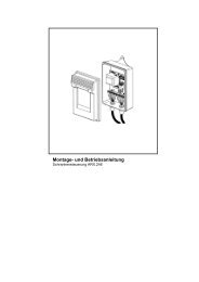
Template BA B168xh238 - bei Berner Torantriebe
Template BA B168xh238 - bei Berner Torantriebe
Template BA B168xh238 - bei Berner Torantriebe

Create successful ePaper yourself
Turn your PDF publications into a flip-book with our unique Google optimized e-Paper software.
ENGLISH<br />
7 .1<br />
▶<br />
▶<br />
7 .2<br />
▶<br />
Instructing users<br />
All persons using the gate system must be shown how to<br />
operate it properly and safely.<br />
Demonstrate and test the mechanical release as well as<br />
the safety return.<br />
Function check<br />
▶<br />
to check the safety reversal, stop<br />
the gate with both hands while it is<br />
closing.<br />
the gate system must stop and<br />
initiate the safety reversal. the gate<br />
system must also switch off and<br />
stop the gate while it is opening.<br />
In the event of a failure of the safety reversal, a specialist<br />
must be commissioned immediately for the inspection<br />
and repair work.<br />
7 .3 Normal mode:<br />
During normal mode, the sliding gate operator only works<br />
according to the impulse sequence control (OpEn-StOp-<br />
ClOSE-StOp). It does not matter whether an external button,<br />
hand transmitter button or print button T has been actuated:<br />
▶ to open and close fully, press the appropriate impulse<br />
generator for channel 1.<br />
▶ to open and close partially, press the appropriate<br />
impulse generator for channel 2.<br />
7 .4 Behaviour during a power failure<br />
to be able to open or close the sliding gate by hand during a<br />
power failure, it must be disengaged from the operator.<br />
ATTENTION!<br />
Damage due to moisture<br />
▶ protect the control from moisture when you open the<br />
operator housing.<br />
1 . Open the housing cover as shown in Figure 3 .1.<br />
2 . Release the operator by turning the locking mechanism.<br />
If necessary, press the motor and toothed wheel down by<br />
hand (see Figure 13 .1).<br />
7 .5 Behaviour following a power failure<br />
Once the power supply has been restored, the gate must be<br />
reengaged with the operator upstream from the limit switch.<br />
▶ Slightly lift the motor while locking it (see Figure 13 .2).<br />
A new reference run is needed after a power failure. this is<br />
automatically performed if an impulse command is pending.<br />
8 Inspection and Maintenance<br />
the sliding gate operator is maintenance-free. For your own<br />
safety, however, we recommend having the gate system<br />
checked by a specialist in accordance with the<br />
manufacturer's specifications .<br />
Inspection and repairs may only be carried out by a qualified<br />
person. Contact your supplier for this purpose. A visual<br />
inspection may be carried out by the operator.<br />
▶ All safety and protective functions must be checked<br />
monthly,<br />
▶ Check the 8k2 resistance contact strips for proper<br />
function every six months.<br />
▶ If necessary, rectify any malfunctions and/or defects<br />
immediately.<br />
9 Operation, Error and Warning<br />
Messages<br />
▶ See lED Gn and lED Rt in Figure 6<br />
9 .1 LED GN<br />
the green lED indicates the operating condition of the<br />
control:<br />
Steady illumination<br />
normal state, all end-of-travel positions and forces<br />
taught-in.<br />
Fast flashing<br />
Force learning runs must be performed.<br />
Slow flashing<br />
Set-up mode – end-of-travel setting<br />
When setting the reversal limits<br />
Flashing frequency is proportional to the selected reversal<br />
limit<br />
• Minimum reversal limit: the green lED flashes 1x<br />
• Maximum reversal limit: the green lED flashes 10x<br />
When setting the hold-open phase<br />
Flashing frequency depends on the set time<br />
• Minimum hold-open phase: lED flashes 1x<br />
• Maximum hold-open phase: lED flashes 5x<br />
9 .2 LED RT<br />
the red lED indicates:<br />
In set-up mode<br />
• limit switch actuated = lED is off<br />
• limit switch not actuated = lED is on<br />
Display of the button inputs, radio<br />
• Actuated = lED is on<br />
• not actuated = lED is off<br />
In normal mode<br />
Flashing code as an error/diagnosis display<br />
9 .3 Error/diagnosis display<br />
the red lED Rt helps to easily identify causes when<br />
operation does not go according to plan.<br />
NOTE:<br />
If normal operation of the sliding gate operator with the radio<br />
receiver or the T button is otherwise possible, a short circuit<br />
in the external button's connecting lead or in the button itself<br />
can be recognised through the behaviour described here.<br />
34 V1.0_D_I / C300_C800 RE / 10.2009