Template BA B168xh238 - bei Berner Torantriebe
Template BA B168xh238 - bei Berner Torantriebe
Template BA B168xh238 - bei Berner Torantriebe

You also want an ePaper? Increase the reach of your titles
YUMPU automatically turns print PDFs into web optimized ePapers that Google loves.
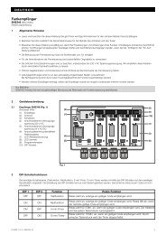
the option relay has the same function as the red lED during<br />
set-up. the limit switch position can be viewed from afar with<br />
a lamp connected to it (see Figure 4 .4).<br />
Teaching in the CLOSE end-of-travel position:<br />
1 . Open the gate halfway.<br />
2 . Set DIL switch 2 (set-up mode) to ON.<br />
the green lED slowly flashes, the red lED remains lit.<br />
3 . press print button T and keep it pressed.<br />
the gate now travels in CLOSE direction at slow speed.<br />
the red lED goes out once the limit switch has been<br />
reached.<br />
4 . Immediately release print button T .<br />
the gate is now in the CLOSE end-of-travel position.<br />
NOTE:<br />
If the gate travels in the opening direction, DIL switch 1 is in<br />
the wrong position and must be reset. then repeat steps<br />
1 to 4.<br />
If the position of the gate does not correspond to the desired<br />
CLOSE position, a readjustment must be made.<br />
Readjusting the CLOSE end-of-travel position:<br />
1 . Adjust the position of the magnet by moving the magnet<br />
slide.<br />
2 . press print button T until the gate reaches the readjusted<br />
end-of-travel position and the red lED goes out.<br />
3 . Repeat steps 1 + 2 until the desired end-of-travel<br />
position has been reached.<br />
4 .2 .2 Recording the OPEN end-of travel position<br />
▶ See Figure 8 .1b<br />
Teaching in the OPEN end-of-travel position:<br />
4 . press print button T and keep it pressed.<br />
the gate now travels in OPEN direction at slow speed.<br />
5 . Release print button T once the required OPEN end-oftravel<br />
position is reached.<br />
6 . press print button P to confirm this position.<br />
the green lED flashes rapidly for 2 seconds to indicate<br />
that the OPEN end-of-travel position has been recorded.<br />
4 .2 .3 Recording the partial opening end-of-travel<br />
position<br />
▶ See Figure 8 .1c<br />
NOTE:<br />
If press-and-hold operation has been set, it is not possible to<br />
record the partial opening end-of-travel position.<br />
Teaching in the partial opening end-of-travel position:<br />
1 . press print button T and keep it pressed to move the<br />
gate back towards the CLOSE position.<br />
2 . Release print button T once the desired partial opening<br />
end-of-travel position is reached.<br />
3 . press print button P to confirm this position.<br />
the green lED flashes slowly to indicate that the partial<br />
opening end-of-travel position has been recorded.<br />
4 .2 .4 Completion of set-up mode<br />
▶ After you have finished the teach-in procedure, set<br />
DIL switch 2 back to OFF.<br />
the green lED signals that forces must be taught in by<br />
flashing quickly.<br />
the safety devices are active again.<br />
4 .2 .5 Reference run<br />
▶ See Figure 8 .2<br />
After teaching in the end-of-travel positions, the first cycle<br />
thereafter is always a reference cycle. During this reference<br />
cycle the option relay clocks and a connected warning light<br />
flashes.<br />
Reference cycle to CLOSE end-of-travel position:<br />
▶ press print button T once.<br />
the operator automatically moves into the CLOSE<br />
end-of-travel position.<br />
▶ If press-and-hold operation has been set, press and hold<br />
print button T until the gate is in the CLOSE end-of-travel<br />
position.<br />
NOTE:<br />
Initial start-up is now finished if press-and-hold operation has<br />
been set (DIL switch 16 to ON).<br />
4 .3 Learning the forces<br />
Once the end-of-travel positions have been taught in and the<br />
reference cycle performed, the forces must be taught in<br />
during force learning runs. For this, three successive gate<br />
cycles must take place, during which none of the safety<br />
devices may be activated. Recording the forces takes place<br />
automatically by press-and-release operation in both<br />
directions. the green lED flashes throughout. this lED is<br />
steadily illuminated once the force learning runs have been<br />
completed (see Figure 9 .1).<br />
▶ Both of the following procedures must be conducted<br />
three times .<br />
Force learning runs:<br />
▶ press print button T once.<br />
the operator automatically moves into the<br />
OPEN end-of-travel position.<br />
▶ press print button T once.<br />
the operator automatically moves into the<br />
CLOSE end-of-travel position.<br />
4 .3 .1<br />
Setting the force limit<br />
WARNING<br />
Danger of injury if force limit is too high<br />
If the force limit has been set too high, the gate will not stop<br />
on time when closing and may trap persons or objects.<br />
▶ Do not set a force limit that is too high.<br />
NOTE:<br />
Due to special fitting situations, it can, however, happen that<br />
the previously taught-in forces prove inadequate which can<br />
lead to undesired reversing. Readjust the forces in such<br />
cases.<br />
the force limit of the gate system is set via a potentiometer<br />
that is labelled Force F on the control print (see Figure 9 .1).<br />
1 . the increase in the force limit is a percentage increase in<br />
relation to the taught-in values where the setting of the<br />
potentiometer denotes the following force increase:<br />
Full left + 0 % force<br />
Centred +15 % force<br />
Full right +75 % force<br />
ENGLISH<br />
V1.0_D_I / C300_C800 RE / 10.2009 29