Betriebsanleitung Stellmotor - lamtec
Betriebsanleitung Stellmotor - lamtec
Betriebsanleitung Stellmotor - lamtec

You also want an ePaper? Increase the reach of your titles
YUMPU automatically turns print PDFs into web optimized ePapers that Google loves.
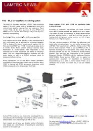
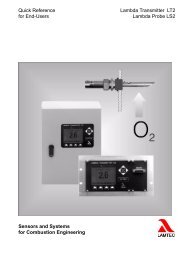
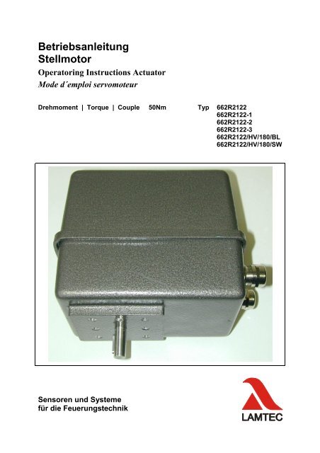
<strong>Betriebsanleitung</strong><br />
<strong>Stellmotor</strong><br />
Operatoring Instructions Actuator<br />
Mode d´emploi servomoteur<br />
Drehmoment | Torque | Couple 50Nm Typ 662R2122<br />
662R2122-1<br />
662R2122-2<br />
662R2122-3<br />
662R2122/HV/180/BL<br />
662R2122/HV/180/SW<br />
Sensoren und Systeme<br />
für die Feuerungstechnik
Inhaltsverzeichnis Table of Content table des matières<br />
Thema<br />
Theme | thème<br />
Kapitel<br />
Chapter | chapitre<br />
Allgemeine Hinweise<br />
General references | indications générales<br />
1<br />
Sicherheitshinweise<br />
Safety References | indications de sécurité<br />
2<br />
Einstellen der Endlagen<br />
Adjust the End Positions | ajuster les situations finales<br />
3<br />
Elektrischer Anschluss<br />
Electrical Connection | raccordement électrique<br />
4<br />
Stromlaufplan<br />
Circuit Diagram| Schéma de circuit<br />
5<br />
Maßzeichnung<br />
Dimensional Drawing | dessin de mesure<br />
6<br />
Technische Daten<br />
Technical Data | data technique<br />
7<br />
EG-Konformitätserklärung<br />
EC Declaration of Confirmity | Déclaration de conformité CE<br />
8
Allgemeine Hinweise General References indications générales<br />
Allgemeine Hinweise<br />
Gültigkeit dieser Anleitung:<br />
Validity of this Manual:<br />
Domaine d’application<br />
Diese Motoren sind ausschließlich zum Antrieb von Stellorganen von<br />
Feuerungsanlagen in Verbindung mit Lamtec Feuerungs und Verbund-<br />
Management Systemen Typ ETAMATIC, FMS oder VMS zugelassen.<br />
Die Art der Rückführung ist formschlüssig ausgeführt. Die Motoren sind<br />
als Stellorgane für ETAMATIC, VMS und FMS zugelassen und<br />
entsprechen den Anforderungen an <strong>Stellmotor</strong>e für diese Geräte.<br />
These control drives are exclusively certified to the drive of<br />
regulating units of combustion plants in connection with<br />
LAMTEC’s firing and compound management systems type<br />
ETAMATIC, FMS and VMS.<br />
The kind of the feedback is positively implemented. The control<br />
drives are certified for ETAMATIC, VMS and FMS and<br />
corresponds to the requirements to control drives for these devices.<br />
L’utilisation de ces moteurs est autorisé pour le positionnement des<br />
clapets d’une chaudière industrielle et doivent uniquement être<br />
raccordé aux automates de commande de type ETAMATIC, FMS,<br />
VMS.<br />
Les caractéristiques de la recopie sont invariantes. Ces moteurs<br />
sont destinés pour être piloter par les automates ETAMATIC, VMS<br />
et FMS et présente les caractéristiques requis pour la<br />
positionnement des clapets pour ces appareils.<br />
Kap. 1
Allgemeine Hinweise General References indications générales<br />
Geräte- Sicherheitsgesetz beachten<br />
Das Geräte-Sicherheitsgesetz schreibt vor:<br />
Gebrauchsanleitung beachten!<br />
Nur nach der hier vorliegenden technischen Dokumentation (Druckschrift<br />
Nr. DLT662R2122) vorgehen.<br />
Geräte nur für die beschriebene Verwendung benutzen.<br />
Bedienung nur durch geschultes Personal. Das Gerät darf nur von<br />
Personen bedient und gewartet werden, die von ihrem Kenntnisstand und<br />
ihrer Ausbildung dazu befähigt sind.<br />
Die Haftung für die Funktion des Gerätes geht in jedem Fall auf den<br />
Eigentümer oder Betreiber über.<br />
Die Haftung für die Funktion des Gerätes geht in jedem Fall auf den<br />
Eigentümer oder Betreiber über soweit das Gerät von Personen, die nicht<br />
über die erforderlichen Kenntnisse verfügen, unsachgemäß betrieben,<br />
gewartet oder instandgesetzt wird oder wenn eine Handhabung erfolgt,<br />
die nicht der bestimmungsgemäßen Verwendung entspricht.<br />
Für Schäden, die durch die Nichtbeachtung der vorstehenden Hinweise<br />
eintreten, haftet die LAMTEC GmbH & Co KG nicht. Gewährleistungsund<br />
Haftungsbedingungen der Verkaufs- und Lieferbedingungen der<br />
LAMTEC GmbH & Co KG werden durch vorstehende Hinweise nicht<br />
erweitert.<br />
Soweit auf Gesetze, Verordnungen und Normen hingewiesen wird, ist die<br />
Rechtsordnung der Bundesrepublik Deutschland zu Grunde gelegt.<br />
Kap. 1
Allgemeine Hinweise General References indications générales<br />
Complying with the Requirements of Equipment Safety Law:<br />
Follow the instructions!<br />
This equipment is to be used only in accordance with these<br />
operating instructions (Document No. DLT662R2122).<br />
The equipment may only be used in the manner described<br />
Operation only by trained personnel. The equipment may only be<br />
operated and serviced by persons who are qualified to do so on the<br />
basis of their expertise and training.<br />
Liability for the functioning of the equipment transferred to<br />
the owner or operator<br />
Liability for the functioning of the equipment shall in all cases be<br />
transferred to the owner or operator if the equipment is improperly<br />
operated, serviced or repaired by persons who do not possess the<br />
necessary expertise, or if the equipment is handled in a manner<br />
other than that prescribed.<br />
LAMTEC GmbH & Co KG will not accept liability for damages<br />
arising from failure to comply with the above instructions. The<br />
above instructions do not extend the warranty and liability<br />
conditions of the Conditions of Sale and Supply of LAMTEC<br />
GmbH & Co KG.<br />
Where reference is made to laws, regulations or standards, these are<br />
based on the legal system of the Federal Republic of Germany.<br />
Kap. 1
Allgemeine Hinweise General References indications générales<br />
Protection et sécurité de l’appareil<br />
La loi de protection de sécurité de l’appareil stipule :<br />
Prendre en considération les indications de la notice d’utilisation<br />
seule les documentations No DLT 662R2122 sont valable<br />
Utiliser seulement l’appareil pour les applications décrites dans<br />
la manuel.<br />
Les détenteurs et utilisateurs de l’appareil sont tenues responsable<br />
des fonctions attribués à l’appareil.<br />
La responsabilité des fonctions de l’appareil sont , dans tous les<br />
cas, attribués à l’utilisateur<br />
La responsabilité des fonctions de l’appareil sont , dans tous les<br />
cas, attribués à l’utilisateur ou propriétaire de l’appareil<br />
indépendamment que les utilisateurs ne disposent les –<br />
connaissances requises ou que l’utilisation ne soit pas conforme à<br />
la notice ou que l’appareil ne soit pas correctement utiliser.<br />
La société LAMTEC GmbH & CO KG dégage toutes<br />
responsabilités pour les dommages causés par le non respect des<br />
indications de la notice d’utilisation.<br />
Les garanties de ventes et de livraisons se sont plus valable lors de<br />
tous non-respect des indications d’utilisation.<br />
Dans la limite de désignation des lois et normes, les droits de la<br />
République fédérale Allemande seront appliquées.<br />
Kap. 1
Sicherheitshinweise für<br />
die Montage<br />
Safety References for the<br />
Assembly<br />
indications de sécurité<br />
d'assemblages<br />
Sicherheitshinweise für die Montage<br />
Je nach dem, zu welchem Zeitpunkt und unter welchen<br />
Umgebungsbedingungen Sie den Stellantrieb montieren, sind spezielle<br />
Sicherheitsaspekte zu berücksichtigen.<br />
• Die Montage und Inbetriebnahme des Antriebes darf nur durch<br />
qualifizierte Fachkräfte erfolgen, die sowohl über fundierte<br />
mechanische als auch elektrische Kenntnisse verfügen!<br />
WARNUNG<br />
Vor einer Montage oder Reparatur eines Stellantriebes sind alle<br />
betroffenen Geräte/Maschinen/Anlagen abzuschalten und<br />
gegebenenfalls vom Netz zu trennen!<br />
• Überzeugen Sie sich, dass pneumatische oder hydraulische<br />
Geräte/Maschinen/Anlagen vor der Montage bzw. Reparatur<br />
drucklos sind oder veranlassen Sie dies. Sollte dies aus<br />
verschiedenen Gründen nicht möglich sein, treffen Sie<br />
Sicherheitsvorkehrungen, das Schäden für Menschen, Umwelt<br />
und Geräte/Maschinen/Anlagen ausgeschlossen werden können!<br />
• Die Verbindung Abtriebswelle Motor muss formschlüssig<br />
erfolgen. Die Verbindung/ Verstiftung muss so dimensioniert<br />
sein, dass bei einer Blockierung des Stellorgans auch der Motor<br />
blockiert. Ein Abscheren, Abreißen der Verbindung muss auch<br />
bei maximalem Drehmoment des Motors ausgeschlossen sein.<br />
Hierbei ist eine Sicherheitsreserve von mind. 50%<br />
einzukalkulieren<br />
• Sichern Sie Ihre Arbeitsstätte ab und stellen Sie sicher, dass die<br />
Geräte/Maschinen/Anlagen, an denen Sie arbeiten, nicht<br />
unbeabsichtigt in Betrieb genommen werden können!<br />
• Bei der Montage oder Reparatur eines Stellantriebes sind die<br />
jeweils zutreffenden berufsgenossenschaftlichen Sicherheitsund<br />
Unfallverhütungsvorschriften zu berücksichtigen!<br />
• Überzeugen sie sich vor der Montage/Reparatur über korrekte<br />
Funktion der Sicherheitseinrichtungen!<br />
WARNUNG<br />
Bei Austausch eines Potentiometers oder Endschalters muss die<br />
Auswirkung auf die Feuerungseinstellung überprüft werden!<br />
Gegebenenfalls muss die Feuerungseinstellung angepasst werden<br />
Kap. 2
Sicherheitshinweise für<br />
die Montage<br />
Safety References for the<br />
Assembly<br />
indications de sécurité<br />
d'assemblages<br />
Safety References for the Assembly<br />
Depending upon that, at which time and under which site conditions<br />
you install the control drive, special safety aspects are to consider.<br />
• The assembly and start-up of the drive may take place only via<br />
qualified specialists, who have both founded mechanical and<br />
electrical knowledge!·<br />
WARNING<br />
Before an assembly or a repair of a control drive all equipment/<br />
machine/plants concerned are to be switched off and if necessary<br />
to be separated from the mains supplement<br />
WARNING<br />
Before switching off device/machine/plants, it is to be examined<br />
compellingly whether switching off cannot exhibit danger<br />
moments. In particular this applies in particular to proceedtechnical<br />
plants!·<br />
• Disconnections are only after previous consultation with the<br />
operating manager, shift leaders or safety engineer to accomplish!<br />
• Disturbances are immediate to announce the operating manager,<br />
shift leader or safety engineer for danger warning!·<br />
• Convince, that pneumatic or hydraulic equipment/machine/plants<br />
before the assembly and/or repair are pressure-free or arrange this.<br />
If this should not be possible for different reasons, meet safety<br />
precautions, which provided damage for humans, environment and<br />
equipment/machine/plants!<br />
• Secure it your working place and guarantee it, that the<br />
equipment/machine/plants, on which you work, can’t be taken<br />
unintentionally starting!·<br />
• When assembling or repair of a control drive, in each case the<br />
applicable safety rules for the prevention of accidents of the<br />
professional association are to be considered!·<br />
• Convince yourselves before the assembly/repair over correct<br />
function of the safety devices!<br />
Kap. 2
Sicherheitshinweise für<br />
die Montage<br />
Safety References for the<br />
Assembly<br />
indications de sécurité<br />
d'assemblages<br />
Indications de sécurité d'assemblages<br />
Selon cela, à quel moment et sous quelles conditions<br />
d'environnement vous installez l'organe de manœuvre, des aspects<br />
de sécurité spéciaux doivent être pris en considération .<br />
• L'assemblage et le démarrage de la commande ne peuvent avoir<br />
lieu que par la main-d’œuvre qualifiée qui dispose des<br />
connaissances mécaniques aussi bien qu'électriques fondées!·<br />
AVERTISSEMENT<br />
Avant un assemblage ou une réparation d'un organe de manœuvre<br />
tous doivent être mis hors circuit installations d'appareil<br />
concernées et séparés éventuellement approvisionnement de<br />
réseau!·<br />
AVERTISSEMENT<br />
Avant de mettre hors circuit des installations d'appareil, il faut<br />
examiner impérativement si mettre ne peut pas montrer de<br />
moments de danger. Cela vaut en particulier pour la douceur<br />
d'opération!<br />
• Des coupures ne doivent être mises en oeuvre que conformément à<br />
entretien précédent avec le directeur de couche, ou l'ingénieur de<br />
sécurité!·<br />
• Pour une prévention des dangers sont des dérangements immédiats<br />
d'annoncer des directeurs de couche ou l'ingénieur de sécurité !·<br />
• Vous convainquez qui des installations d'appareil pneumatiques ou<br />
hydrauliques avant l'assemblage et/ou la réparation sont sans<br />
pression ou vous provoquez cela. Si cela ne devait pas être possible<br />
pour différentes raisons, vous rencontrez des mesures de sécurité,<br />
dommages pour des hommes, environnement et des installations<br />
d'appareil être exclu pouvez!·<br />
• Assurez et garantissez votre lieu de travail ils que les installations<br />
d'appareil, auquel vous travaillez, ne peuvent pas être mises en<br />
service involontairement!<br />
• Avec l'assemblage ou la réparation d'un organe de manœuvre, les<br />
règlements de prévoyance contre les accidents et de sécurité<br />
professionnels respectivement justes doivent être pris en<br />
considération !·<br />
• Vous convainquez avant l'assemblage/réparation sur la fonction<br />
correcte des dispositifs de sécurité!<br />
Kap. 2
Sicherheitshinweise für<br />
die Einstellungen<br />
Safety References for the<br />
Attitudes<br />
indications de sécurité<br />
de réglages<br />
Sicherheitshinweise für die Einstellungen<br />
WARNUNG<br />
Stellen Sie sicher, dass durch die Inbetriebnahme bzw. durch die<br />
Testeinstellungen keine Gefahr für Mensch, Umwelt und Geräte/<br />
Maschinen/Anlagen entstehen kann!<br />
WARNUNG<br />
Vergewissern Sie sich, dass die volle Bewegungsfreiheit der<br />
Stellantriebe gewährleistet ist und für das Personal keine<br />
Quetschgefahr besteht! Errichten Sie gegebenenfalls<br />
Absperrungen!<br />
WARNUNG<br />
Bei der Arbeit an geöffneten und betriebsbereiten Stellantrieben<br />
besteht die Gefahr, das spannungsführende Teile (24/115/230/400V<br />
AC~) berührt werden können! Das Montagepersonal sollte deshalb<br />
entsprechend qualifiziert sein und sich dieser potentiellen Gefahr<br />
bewusst sein!<br />
• Sichern Sie den Arbeitsbereich der Geräte/Maschine/Anlagen gegen<br />
unbeabsichtigte In- oder Außerbetriebnahme ab!<br />
• Überprüfen Sie nach Abschluss der Einstellungen, ob die elektrischen<br />
Signale des Stellantriebe, insbesondere die Stellungsrückmeldung<br />
(optional), mit der mechanischen Stellung des Antriebes übereinstimmt!<br />
Dies gilt insbesondere für die Endlagen!<br />
• Abschließend überprüfen Sie die Funktion eventueller<br />
Sicherheitseinrichtungen auf Fehlerfreiheit!<br />
• Stellen Sie vor Inbetriebnahme sicher, dass die Endschalter derart<br />
justiert sind, dass das Stellorgan nicht auf mechanischen Anschlag läuft.<br />
Dies kann wegen erhöhter Stromaufnahme das Ansteuerorgan oder den<br />
Motor beschädigen.<br />
Kap. 2
Sicherheitshinweise für<br />
die Einstellungen<br />
Safety References for the<br />
Attitudes<br />
indications de sécurité<br />
de réglages<br />
Safety References for the Attitudes<br />
WARNING<br />
Guarantee that from start-up and/or from the test attitudes no<br />
danger for humans, environment and equipment/machine/plants<br />
can result!··<br />
WARNING<br />
Make sure that the full freedom of movement of the control drives<br />
is ensured and exists for the personnel no squeezing danger!<br />
Establish to shut-off positions if necessary!·<br />
WARNING<br />
With the work on opened and ready for use control drives exists<br />
the danger, which live dividing (24/115/230/400V AC~) can be<br />
affected! The assembly personnel should be accordingly qualified<br />
therefore and be conscious this potential danger!<br />
• Secure the work area of the equipment/machine/plants against<br />
unintentional in or putting out of operation!·<br />
• Examine after conclusion of the attitudes whether the electrical<br />
signals control drives, in particular the position feedback (optional),<br />
with which mechanical position of the drive agrees! This applies in<br />
particular to the end positions!·<br />
• Finally you examine the function of possible safety devices for<br />
accuracy!<br />
Kap. 2
Sicherheitshinweise für<br />
die Einstellungen<br />
Safety References for the<br />
Attitudes<br />
indications de sécurité<br />
de réglages<br />
Indications de sécurité de réglages<br />
AVERTISSEMENT<br />
Garantissez que de démarrage et/ou de réglages d'essai, aucun<br />
danger pour homme, environnement et des installations d'appareil<br />
ne peut naître!<br />
AVERTISSEMENT<br />
Vous assurez que la liberté de mouvement pleine des organes de<br />
manœuvre est garantie et ne réussit pas pour le personnel de<br />
danger de compression! établissez éventuellement des barrages!<br />
AVERTISSEMENT<br />
Avec le travail sur des organes de manœuvre ouverts et prêts à<br />
démarrer, le danger existe qui des parties vivantes<br />
(24/115/230/400V AC~) peuvent être affectées! Le personnel<br />
d'assemblage devrait être en conséquence qualifié par conséquent<br />
et être conscient ce danger potentiel!<br />
• Assurez la zone de travail des installations d'appareil contre une<br />
mise hors service ou de dans non voulue!· ·<br />
• Réexaminez après la conclusion des réglages si les signaux<br />
électriques organes de manœuvre, en particulier la reconnaissance<br />
de position (optionnellement), à laquelle la position mécanique de<br />
la commande correspond! Cela vaut en particulier pour les<br />
situations finales!<br />
• Pour finir, vous réexaminez la fonction d'éventuels dispositifs de<br />
sécurité sur la précision<br />
Kap. 2
Gerätesicherheit Equipment Safety Sécurité de l'appareil<br />
Gerätesicherheit<br />
• Die Stellantriebe sind nach anerkannten Regeln der Technik hergestellte<br />
Qualitätsprodukte und haben das Herstellerwerk in sicherheitstechnisch<br />
einwandfreien Zustand verlassen!<br />
• Zur Erhaltung des sicherheitstechnisch einwandfreien Zustandes ist es<br />
zwingend notwendig, dass Monteur/Anwender sich strikt an die<br />
Herstellerangaben aus dieser Dokumentation halten und über eine<br />
entsprechende berufliche Qualifikation verfügen.<br />
• Die Stellantriebe dürfen nur zu dem ihrer Bauart entsprechenden Zweck<br />
verwendet werden!<br />
• Ebenso dürfen die Stellantriebe nur entsprechend der in den technischen<br />
Daten vorgegebenen Werte betrieben werden!<br />
WARNUNG<br />
Stellen Sie sicher, dass durch die Montage, Inbetriebnahme oder<br />
durch den Testbetrieb am Stellantrieb keine Gefahr für Mensch,<br />
Umwelt oder Geräte/ Maschinen/ Anlagen entstehen kann!<br />
• Vor der Montage des Stellantriebes ist das Stellglied auf Leichtgängigkeit<br />
zu überprüfen!<br />
• Die Stellantriebe dürfen weder an schadhaften Zuleitungen bzw.<br />
angeflanschten Anlagenteilen montiert, in Betrieb genommen, noch<br />
dürfen Einstellarbeiten an ihnen vorgenommen werden! Das gleiche gilt<br />
auch für beschädigte Stellantriebe!<br />
• Nach Abschluss der Montage bzw. der Einstellungen ist die korrekte<br />
Funktion und gegebenenfalls die Einhaltung der Endlagen zu prüfen!<br />
• Nach Abschluss der Montage bzw. der Einstellungen ist die korrekte<br />
Funktion und gegebenenfalls die Einhaltung der Endlagen zu prüfen!<br />
• Ebenfalls ist die Funktion optionaler Komponenten zu prüfen!<br />
Kap. 2
Gerätesicherheit Equipment Safety Sécurité de l'appareil<br />
Equipment Safety<br />
• The control drives are according to recognized rules of the<br />
technology manufactured quality products and the manufacturer in<br />
safety-relevant perfect condition left!·<br />
• For the preservation of the safety-relevant perfect condition it is<br />
compellingly necessary that mechanic/users adheres strict to the<br />
manufacturer data from this documentation and has an appropriate<br />
vocational qualification!·<br />
• The control drives may be used only for that its design<br />
corresponding purpose!<br />
• Likewise the control drives may be operated only according to the<br />
values given in the technical data!<br />
WARNING<br />
Guarantee that from the assembly, start-up cannot result or from<br />
the test operation at the control drive a danger for humans,<br />
environment or devices/machines/plants!<br />
• Before the assembly of the control drive the control member is to be<br />
examined for operation smoothness!·<br />
• The control drives may neither at defective inlets and/or flanged on<br />
components installed, in enterprise taken, nor tuning at them may be<br />
made! The same applies also to damaged control drives!<br />
• After conclusion of the assembly and/or the attitudes the correct<br />
function and the adherence to the end positions are to be examined<br />
if necessary!·<br />
• Likewise the function of optional components is to be examined!<br />
Kap. 2
Gerätesicherheit Equipment Safety Sécurité de l'appareil<br />
Sécurité de l'appareil<br />
• Les organes de manœuvre ont été des produits de qualité fabriqués<br />
après les règles reconnues de la technique et ont quitté le travail de<br />
fabricant dans un état à l'égard de règlements de sécurité parfait!·<br />
• L'état à l'égard de règlements de sécurité parfait il est<br />
impérativement nécessaire pour recevoir que le<br />
assembleur/utilisateurs s'en tienne stricts aux données du fabricant<br />
de cette documentation et dispose d'une qualification<br />
professionnelle correspondante.<br />
• Les organes de manœuvre ne peuvent être utilisés qu'à cela de leur<br />
conception but correspondant!·<br />
• Aussi les organes de manœuvre ne peuvent être actionnés que<br />
conformément les valeurs alléguées dans les données techniques!·<br />
AVERTISSEMENT<br />
Garantissez que d'assemblage, le démarrage ne peut pas naître ou<br />
d'exploitation type à l'organe de manœuvre, de danger pour<br />
homme, environnement ou des appareils/machines/installations!·<br />
• Avant l'assemblage de l'organe de manœuvre, l'organe de réglage<br />
doit être réexaminé pour la douceur d'opération!<br />
• Ne pouvoir ni à des transmissions défectueuses et/ou à des<br />
composants à fixation par flasques installé, mis en service les<br />
organes de manœuvre, ni des travaux de réglage sur eux peuvent<br />
être entrepris! La même chose vaut aussi pour des organes de<br />
manœuvre endommagés!<br />
• Après la conclusion de l'assemblage et/ou des réglages, la fonction<br />
correcte et éventuellement l'observation des situations finales<br />
doivent être examinées !<br />
• La fonction de composantes optionnelles doit également être<br />
examinée !<br />
Kap. 2
Einstellen der Endlagen<br />
Adjust the End Positions<br />
ajuster les situations<br />
finales<br />
Einstellen der Wegendschalter<br />
Adjusting the End Position Switch<br />
Die Wegendschalter mit Spitznocken 15° sind werkseitig eingestellt. Die<br />
Feinjustierung erfolgt mit Schraubendreher an Schraube „F“. Schraube<br />
drehen, bis ein leichtes Klicken des Schalters zu hören ist.<br />
Zur Kontrolle, die Schaltposition elektrisch anfahren, wenn notwendig<br />
nachjustieren und Stiftschraube „S“ mit 1,5 mm Inbusschlüssel auf Nokkenwelle<br />
befestigen. Die Feinjustierung erfolgt wie bei Wegendschalter<br />
mit Schraubendreher an Schraube „F“. Schraube drehen, bis ein Klicken<br />
des Schalters zu hören ist. Durch elektrische Drehbewegung die Schaltposition<br />
überprüfen, Schraube „S“ anziehen und gegen Lösen sichern.<br />
The end position switches with the 15° conical cams are factorypreset.<br />
For fine adjustment turn screw “F” with a screw driver until<br />
the switch clicks slightly.<br />
For a check start the switching position electrically, readjust it if<br />
necessary and tighten stud bold “S”. On delivery displacement<br />
transducer switches with trigger cams 180° are set loosely on the<br />
camshaft which is-at the same time- the drive shaft. Fasten the<br />
trigger cam with stud bolt “S” and 1,5mm wrench slightly on the<br />
distribution shaft. For a fine adjustment (like for the stop position<br />
switch) turn screw “F” with a screw driver until the switch clicks<br />
slightly. Check the switching position via electrical rotation,<br />
tighten screw “S” and lock it.<br />
L'interrupteur de fin de course de manière<br />
Les interrupteurs de fin de course de manière avec la came pointue<br />
15° ajustent . L'ajustement de précision a lieu avec des tournevis à<br />
la vis "F". Tourner la vis, jusqu'à ce qu'il faille entendre cliqueter<br />
facile du commutateur. Au contrôle que position de distribution<br />
commencer électriquement, si et attachent le goujon des "s"<br />
rajustent nécessairement avec 1,5 mm hexagone clé sur l'arbre à<br />
cames. L'ajustement de précision a lieu comme avec des<br />
interrupteurs de fin de course de manière avec des tournevis à la<br />
vis "F". Tourner la vis, jusqu'à ce qu'il faille entendre cliqueter du<br />
commutateur . Par un mouvement de rotation électrique la position<br />
de distribution réexaminer et la vis "S" serrer et contre résoudre<br />
assurer.<br />
Kap. 3
Elektrischer Anschluss Electrical Connection Raccordement électrique<br />
Elektrischer Anschluss<br />
Es sind die VDE- und EVU-Vorschriften beim Anklemmen der<br />
Regelantriebe zu beachten und sollten nur von einem zugelassenen<br />
Fachmann angeschlossen werden. Beachten Sie den in der Haube<br />
eingeklebten Anschlussplan und die außen am Stellantrieb angegebenen<br />
technischen Angaben. Sämtliche Funktionen, wie Endschalter,<br />
Potentiometer oder sonstige Optionen, sind werkseitig verdrahtet, die<br />
Wegendschalter ca. 90 oder 180° eingestellt.<br />
Electrical Connection<br />
VDE and EVU specifications have to be observed when connecting<br />
our actuator motors. Connections are to be executed by an<br />
authorized specialist only. Please follow the connection diagram<br />
glued to the inside of the top as well as the technical information<br />
found on the outside of the actuating drives. All functions like end<br />
switches, potentiometers and other options are aiready wired, stop<br />
position switches are preset to 90 or180°.<br />
Raccordement électrique<br />
Tenir compte des prescriptions VDE et EVU pour la connexion des<br />
mécanismes de commande. Le raccordement ne doit être effectué<br />
que par du personnel spécialisé autorisé. Veuillez tenir compte du<br />
schéma de raccordement collé à l'intérieur du capot ainsi que des<br />
informations techniques à l'extérieur du mécanisme de commande.<br />
Toutes les fonctions comme commutateurs de fin de course,<br />
potentiomètres et autres options sont câblées à l'usine, les<br />
commutateurs de fin de course réglés à env. 90 ou 180°.<br />
Kap. 4
Elektrischer Anschluss Electrical Connection Raccordement électrique<br />
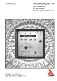
Kundenseitige Anschlüsse an Anschlussplatine MST 5<br />
Regelantrieb mit AC Synchronmotor<br />
Connections Provided by the Customer at Connection Plate MST5<br />
Actuator with AC Synchronous Motor<br />
Raccordements chez le client à la plaque de raccordement MST5<br />
mécanisme de commande avec AC moteur synchrone<br />
Poti 2<br />
(Option)<br />
Poti 1<br />
Kap. 4
Elektrischer Anschluss Electrical Connection Raccordement électrique<br />
Klemme1:<br />
An dieser Klemme wird der Schutzleiter angeschlossen.<br />
Dieser hat wie der Name schon sagt eine reine Schutzfunktion. Das<br />
heißt alle elektrisch leitenden Teile sind nach Anschluss des<br />
Schutzleiters mit dem Potential "Erde" verbunden.<br />
Klemme 2:<br />
An dieser Klemme wird er Neutralleiter angeschlossen.<br />
Dieser bewirkt, das bei Bedarf ein Stromfluss zustande kommen kann.<br />
Klemme 14:<br />
Klemme 13:<br />
Wird an dieser Klemme eine Spannung angelegt, bewirkt dies eine<br />
Drehbewegung des Antriebs in positive Richtung. (Drehbewegung vom<br />
Deckel aus gesehen im Uhrzeigersinn).<br />
Wird der Mikroschalter S1 durch die Schaltnocke betätigt wird die<br />
Drehbewegung unterbrochen(der Antrieb steht).<br />
Wird an Klemme 14 die Spannung unterbrochen, stoppt die<br />
Drehbewegung ebenso.<br />
Wird an dieser Klemme eine Spannung angelegt bewirkt dies eine<br />
Drehbewegung des Antriebs in negative Richtung (Drehbewegung vom<br />
Deckel aus gesehen gegen den Uhrzeigersinn).<br />
Wird der Mikroschalter S2 durch die Schaltnocke betätigt wird die<br />
Drehbewegung unterbrochen (der Antrieb steht).<br />
Wird an Klemme 13 die Spannung unterbrochen, stoppt die<br />
Drehbewegung ebenso.<br />
WARNUNG<br />
Es darf niemals gleichzeitig eine Spannung an<br />
Klemme 13 und an Klemme 14 anliegen!<br />
Klemme 4:<br />
Ist Schalter S1 betätigt und Spannung an Klemme 14, liegt hier eine<br />
Spannung an, die für Steuerungszwecke weiter verwendet werden kann.<br />
Klemme 3:<br />
Ist Schalter S2 betätigt und Spannung an Klemme 13, liegt hier eine<br />
Spannung an, die für Steuerungszwecke weiter verwendet werden kann.<br />
Klemme 12:<br />
L1 Manuell, wird an dieser Klemme eine Spannung angeschlossen kann<br />
der Antrieb mittels den zwei Tastern auf der Platine von Hand verfahren<br />
werden. (optional)<br />
Kap. 4
Elektrischer Anschluss Electrical Connection Raccordement électrique<br />
Klemme 8, 9, 10:<br />
Potentiometer 1 (5kR)<br />
bei Abgriff zwischen Klemme 8 und 9 steigt der Widerstandswert, wenn<br />
Drehbewegung in negative Richtung (Spannung an Klemme 13)<br />
Klemme 6, 15, 5:<br />
Zusatzschalter S3, potentialfrei<br />
Klemme 6: Öffner von S3<br />
Klemme 15: Wurzel von S3<br />
Klemme 5: Schließer von S3<br />
Klemme 16, 7, 17:<br />
Zusatzschalter S4, potentialfrei<br />
Klemme 16: Öffner von S4<br />
Klemme 7: Wurzel von S4<br />
Klemme 17: Schließer S4<br />
Klemme 18, 19, 20:<br />
Potentiometer 2 (optional)<br />
bei Abgriff zwischen Klemme 18 und 19 steigt der Widerstandswert,<br />
wenn Drehbewegung in negative Richtung (Spannung an Klemme 13)<br />
Kap. 4
Elektrischer Anschluss Electrical Connection Raccordement électrique<br />
Terminal 1:<br />
Holds the protective conductor witch is used -as indicated by the<br />
name- for protective function only. All conductive parts are<br />
thereby connected to ground.<br />
Terminal 2:<br />
Holds the neutral conductor to provide for current flow, if<br />
necessary.<br />
Terminal 14:<br />
Terminal 13:<br />
A voltage applied to this terminal initiates a rotation of the drive in<br />
positive direction (clockwise, seen from the lid). When actuated by<br />
the switching cam, micro switch S1 terminates the rotation (the<br />
actuator stops). Disconnecting voltage to terminal 14 also stops the<br />
rotation.<br />
A voltage applied to this terminal initiates a rotation of the drive in<br />
negative direction (anticlockwise, seen from the lid). When<br />
actuated by the switching cam, micro switch S2 terminates the<br />
rotation (the actuator stops). Disconnecting voltage to terminal 13<br />
also stops the rotation.<br />
WARNING<br />
It is not possible to have, at one time, voltage applied<br />
to both terminals 13 and 14!<br />
Terminal 4: If switches S1 is actuated and voltage applied to terminal no. 14,<br />
terminal 4 provides a voltage which can be used for control<br />
purposes<br />
Terminal 3: If switch S2 is actuated and voltage applied to terminal no. 13,<br />
terminal 5 provides a voltage which can be used for control<br />
purposes.<br />
Terminal 12:<br />
L1 manual, attached at this terminal a tension can the drive by<br />
means of the two tracers on the plate be proceeded by hand<br />
(optionally)<br />
Kap. 4
Elektrischer Anschluss Electrical Connection Raccordement électrique<br />
Terminal 8, 9, 10:<br />
Terminal 5, 15, 6:<br />
Terminal 16, 7, 17:<br />
Terminal 18,19,20:<br />
Potentiometer 1 (5kR)<br />
Pick-up between terminal 8 and 9 increases resistance value during<br />
rotation in negative direction (voltage applied to terminal no. 13).<br />
Additional switch S3, floating<br />
Terminal 6: nc-contact S3 (normally close)<br />
Terminal 15: root S3<br />
Terminal 5: no-contact S3 (normally open)<br />
Additional switch S4, floating<br />
Terminal 16: nc-contact S4 (normally close)<br />
Terminal 7: root S4<br />
Terminal 17: no-contact S4 (normally open)<br />
Potentiometer 2 (optionally):<br />
Pick-up between terminal 18 and 19 increases resistance value<br />
during rotation in negative direction (voltage applied to terminal no.<br />
13).<br />
Kap. 4
Elektrischer Anschluss Electrical Connection Raccordement électrique<br />
Borne 1:<br />
Borne 2:<br />
Raccord du fil de protection a cette borne. Comme son nom<br />
l'indique, ce fil a une pure fonction de protection. Cela signifie que<br />
toutes les pièces a conduction électrique sont connectées au<br />
potentiel "terre" après le raccord du fil de protection.<br />
Raccord du conducteur neutre a cette borne. Cela a pour effet<br />
qu'en cas de besoin une conduction de courant est possible<br />
Borne 14:<br />
Borne 13:<br />
L'application d'une tension a cette borne génère un mouvement de<br />
rotation de l'entraînement en sens positif. (vu du couvercle,<br />
mouvement de rotation dans le sens d'une aiguille d'une montre).<br />
Lorsque le micro rupteur S1 est actionne par la came de<br />
commande, le mouvement de rotation est interrompu<br />
(l'entraînement s'immobilise).<br />
Lorsque la tension est coupée a la borne 14, le mouvement de<br />
rotation s'arrête également.<br />
L'application d'une tension a cette borne génère un mouvement de<br />
rotation de l'entraînement sensé négatif. (vu du couvercle,<br />
mouvement de rotation contre le sens d'une aiguille d'une montre).<br />
Lorsque le micro rupteur S2 est actionne par la came de<br />
commande, le mouvement de rotation est interrompu<br />
(l'entraînement s'immobilise).<br />
Lorsque la tension est coupée a la borne 13, le mouvement de<br />
rotation s'arrête également.<br />
AVERTISSEMENT<br />
La tension ne doit jamais être appliquée simultanément aux<br />
bornes 13 et 14!<br />
Borne 4:<br />
Borne 3:<br />
Borne 12:<br />
Lorsque le commutateur S1 est actionne et que la tension est appliquée<br />
a la borne 14, il y a ici une tension, pouvant encore être utilisée a des<br />
fins de commande.<br />
Lorsque le commutateur S2 est actionne et que la tension est appliquée<br />
a la borne 13, il y a ici une tension, pouvant encore être utilisée a des<br />
fins de commande.<br />
L1 manuelle, lorsqu'une tension est appliquée a cette borne,<br />
l'entraînement peut être déplace a la main sur la platine au moyen de<br />
deux poussoirs (optionnellement).<br />
Kap. 4
Elektrischer Anschluss Electrical Connection Raccordement électrique<br />
Borne 8, 9, 10:<br />
Borne 5, 15, 6:<br />
Borne 16, 7, 17:<br />
Borne 18,19,20:<br />
Potentiomètre 1 (5kR)<br />
pour le ramassage entre le borne 8 et 9, la valeur de résistance<br />
augmente, si mouvement de rotation dans une négative direction<br />
(tension au borne 13)<br />
Commutateur S3, sans potentiel<br />
Borne 6 : contact a ouverture de S3<br />
Borne 15 : racine de S3<br />
Borne 5 : contact a fermeture de S3<br />
Commutateur S4, sans potentiel<br />
Borne 16 : contact a ouverture de S4<br />
Borne 7 : Racine de S4<br />
Borne 17 : contact a fermeture de S4<br />
Potentiomètre 2 (optionnellement).<br />
Pour le ramassage entre le borne 18 et 19, la valeur de résistance<br />
augmente, si mouvement de rotation dans une négative direction<br />
(tension au borne 13)<br />
Kap. 4
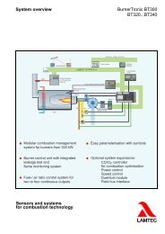
Stromlaufplan Circuit Diagram Schéma de circuit<br />
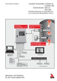
Stromlaufplan MST5 mit max. 2 Zusatzschalter und 2 Potentiometer<br />
Circuit diagram MST5 with max. 2 additional switches and 2 potentiometers<br />
Schéma de circuit MST5 avec max. 2 interrupteurs additionnelles et 2 potentiomètres.<br />
Kap. 5
Maßzeichnung Dimensional Drawing Dessin de mesure<br />
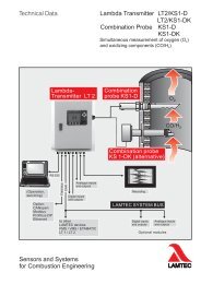
Wellenendformen<br />
Forms of the end of the shaft<br />
Formes de fin de arbre<br />
WARNUNG / WARNING / ATTENTION:<br />
Bei Verbindung mit den Regelklappen Sicherheitshinweise beachten !<br />
Consider safety references when connecting with the control damper.<br />
Par la connexion avec les clapets de réglage, veuillez prendre en<br />
considération les recommandations de sécurité.<br />
Kap. 6
Maßzeichnung Dimensional Drawing Dessin de mesure<br />
Antrieb 662 R2122<br />
Control drive 662 R2122<br />
Organes de manœuvre 662 R2122<br />
Kap. 6
Technische Daten Technical Data data technique<br />
Typ 662 R2122<br />
STANDARD<br />
Spannung [V]<br />
voltage | tension<br />
Netzfrequenz [Hz]<br />
mains frequency | fréquence secteur<br />
Aufnahmeleistung [VA]<br />
power input | performance d’admission<br />
Abgabeleistung [W]<br />
power output | performance de livraison<br />
Stromaufnahme [mA]<br />
current | puissance absorbée<br />
Kondensator [µF / V]<br />
capacitor | condensateur<br />
11,0<br />
5,1<br />
DC<br />
model 662 R2122<br />
STANDARD<br />
type 662 R2122<br />
STANDARD<br />
24 115 230 400<br />
50 X<br />
60<br />
48 (230V) 80 (115V)<br />
0,22 / 500 (230V) 1,3 / 250 (115V)<br />
Getriebe transmission boîte de vitesses<br />
Platinengetriebe<br />
plate transmission | engrenage à platine<br />
Zahnräder<br />
gear wheels | roues dentées<br />
Material<br />
material | matériau<br />
Laufzeit [s/90°]<br />
operating time | temps d’exécution<br />
Drehmoment [Nm]<br />
torque | couple<br />
Selbsthaltemoment [Nm]<br />
self retaining moment | couple d’auto moment<br />
stirnverzahnt<br />
fronttoothed | front engrener<br />
ETG 100<br />
60<br />
50<br />
40<br />
Lagerung<br />
CuZn40 AL2 wartungsfrei<br />
bearing | roulement<br />
CuZn40 AL2 maintenance free | CuZn40 AL2 sans entretien<br />
Gehäuse housing boîtier<br />
Oberteil<br />
upper part | partie supérieure<br />
Unterteil<br />
bottom part | partie inférieure<br />
Schutzart<br />
type of protection | degré de protection<br />
Umgebungstemperatur [°C]<br />
ambient temperature | température ambiante<br />
Adaption<br />
adaption | adaptions<br />
Abtriebswelle [mm]<br />
output shaft | arbre d’entraînement<br />
Kraftübertragung<br />
power transmission | transmission<br />
Verschraubungen<br />
cable entries | entrées de câble<br />
Abmessungen [mm]<br />
dimensions | dimensions<br />
Aluminium-Sandguss, Hammerschlag lackiert<br />
aluminium sand-cast, hammer dimple enamel | aluminium coulé en sable laqué à effet martelé<br />
Aluminium-Sandguss,<br />
aluminium sand-cast | aluminium coulé en sable<br />
IP65<br />
-10 bis 60<br />
Lochkreis Ø 50mm, 4 x 90°, M6 / ISO 5211 F07<br />
circle of holes Ø 50 mm, 4 x 90°, M6 / ISO 5211 F07 | cercle de trous Ø 50 mm, 4 x 90°, M6 / ISO 5211 F07<br />
Ø12 x 30 , Form C<br />
Passfeder DIN 6885-A-4x4x20-1.4571<br />
parallel key DIN 6885-A-4x4x20-1.4571 | clavette parallèle fixée par vis DIN 6885-A-4x4x20-1.4571<br />
2x M20x1,5<br />
Länge<br />
length | longueur<br />
210,0 Breite<br />
width | largeur<br />
130,0 Höhe<br />
height | hauteur<br />
163,0<br />
Gewicht [kg]<br />
ca. 3,3<br />
weight | poids<br />
Zubehör accessories accessoires<br />
Wegendschalter<br />
2<br />
limit switch | commutateur de fin de course<br />
2 zusätzliche Schalter (potentialfrei)<br />
additional switches (floating) | commutateurs supplémentaires (dont hors potentiel)<br />
1<br />
Potentiometer 0 – 5 K-Ohm, Fabrikat Novotechnik, TÜV zugelassen. Verbindung des<br />
Potentiometers mit Abtriebswelle durch Zahnräder, spielfrei und formschlüssig.<br />
Potentiometer 0 – 5 k-Ohm, type Novotechnik, TÜV certified. Connection of the potentiometer with output shaft by gear wheels, no hysteresis between<br />
potentiometer and output shaft.<br />
Potentiomètre 0 – 5 k-Ohm, marque Novotechnik, homologué par le TÜV. Liaison complète, sans jeu, entre le potentiomètre et l’arbre d’entraînement par des<br />
roues dentées.<br />
2 elektrische Handverstellung (Rechtslauf / Linkslauf)<br />
electrical hand operated control (clockwise /anti-clockwise rotation) | réglage de l’allumage à main électrique (marche à droite / commutateur marche à gauche)<br />
Kap. 7
Technische Daten Technical Data data technique<br />
Typ 662 R2122-1<br />
Adaption auf ARIS Wan 4A<br />
Spannung [V]<br />
voltage | tension<br />
Netzfrequenz [Hz]<br />
mains frequency | fréquence secteur<br />
Aufnahmeleistung [VA]<br />
power input | performance d’admission<br />
Abgabeleistung [W]<br />
power output | performance de livraison<br />
Stromaufnahme [mA]<br />
current | puissance absorbée<br />
Kondensator [µF / V]<br />
capacitor | condensateur<br />
11,0<br />
5,1<br />
DC<br />
50<br />
60<br />
model 662 R2122-1<br />
adaption to ARIS Wan 4A<br />
type 662 R2122-1<br />
adapteur ARIS Wan 4A<br />
24 115 230 400<br />
X<br />
48 (230V) 80 (115V)<br />
0,22 / 500 (230V) 1,3 / 250 (115V)<br />
Getriebe transmission boîte de vitesses<br />
Platinengetriebe<br />
plate transmission | engrenage à platine<br />
Zahnräder<br />
gear wheels | roues dentées<br />
Material<br />
material | matériau<br />
Laufzeit [s/90°]<br />
operating time | temps d’exécution<br />
Drehmoment [Nm]<br />
torque | couple<br />
Selbsthaltemoment [Nm]<br />
self retaining moment | couple d’auto moment<br />
stirnverzahnt<br />
fronttoothed | front engrener<br />
ETG 100<br />
60<br />
50<br />
40<br />
Lagerung<br />
CuZn40 AL2 wartungsfrei<br />
bearing | roulement<br />
CuZn40 AL2 maintenance free | CuZn40 AL2 sans entretien<br />
Gehäuse housing boîtier<br />
Oberteil<br />
upper part | partie supérieure<br />
Unterteil<br />
bottom part | partie inférieure<br />
Schutzart<br />
type of protection | degré de protection<br />
Umgebungstemperatur [°C]<br />
ambient temperature | température ambiante<br />
Adaption<br />
adaption | adaptions<br />
Abtriebswelle [mm]<br />
output shaft | arbre d’entraînement<br />
Kraftübertragung<br />
power transmission | transmission<br />
Verschraubungen<br />
cable entries | entrées de câble<br />
Abmessungen [mm]<br />
dimensions | dimensions<br />
Aluminium-Sandguss, Hammerschlag lackiert<br />
aluminium sand-cast, hammer dimple enamel | aluminium coulé en sable laqué à effet martelé<br />
Aluminium-Sandguss,<br />
aluminium sand-cast | aluminium coulé en sable<br />
IP65<br />
-10 bis 60<br />
Lochkreis Ø 50mm, 4 x 90°, M6 / ISO 5211 F07<br />
circle of holes Ø 50 mm, 4 x 90°, M6 / ISO 5211 F07 | cercle de trous Ø 50 mm, 4 x 90°, M6 / ISO 5211 F07<br />
Ø12 x 40 , Form C mit Querbohrung 5mm<br />
With additional drilling 5mm<br />
Passfeder DIN 6885-A-4x4x20-1.4571<br />
parallel key DIN 6885-A-4x4x20-1.4571 | clavette parallèle fixée par vis DIN 6885-A-4x4x20-1.4571<br />
2x M20x1,5<br />
Länge<br />
length |<br />
longueur<br />
210,0 Breite<br />
width | largeur<br />
130,0 Höhe<br />
height | hauteur 163,0<br />
Gewicht [kg]<br />
ca. 3,3<br />
weight | poids<br />
Zubehör accessories accessoires<br />
Wegendschalter<br />
2<br />
limit switch | commutateur de fin de course<br />
2 zusätzliche Schalter (potentialfrei)<br />
additional switches (floating) | commutateurs supplémentaires (dont hors potentiel)<br />
1<br />
Potentiometer 0 – 1kOhm, Fabrikat Contelec, TÜV zugelassen. Verbindung des<br />
Potentiometers mit Abtriebswelle durch Zahnräder, spielfrei und formschlüssig.<br />
Potentiometer 0 – 1 kOhm, type Contelec, TÜV certified. Connection of the potentiometer with output shaft by gear wheels, no hysteresis between potentiometer<br />
and output shaft.<br />
Potentiomètre 0 – 1 kOhm, marque Contelec, homologué par le TÜV. Liaison complète, sans jeu, entre le potentiomètre et l’arbre d’entraînement par des roues<br />
dentées.<br />
2 elektrische Handverstellung (Rechtslauf / Linkslauf)<br />
electrical hand operated control (clockwise /anti-clockwise rotation) | réglage de l’allumage à main électrique (marche à droite / commutateur marche à gauche)<br />
Kap. 7
Technische Daten Technical Data data technique<br />
Typ 662 R2122-2 model 662 R2122-2 type 662 R2122-2<br />
Spannung [V]<br />
voltage | tension<br />
Netzfrequenz [Hz]<br />
mains frequency | fréquence secteur<br />
Aufnahmeleistung [VA]<br />
power input | performance d’admission<br />
Abgabeleistung [W]<br />
power output | performance de livraison<br />
Stromaufnahme [mA]<br />
current | puissance absorbée<br />
Kondensator [µF / V]<br />
capacitor | condensateur<br />
11,0<br />
5,1<br />
DC<br />
24 115 230 400<br />
50 X<br />
60<br />
48 (230V) 80 (115V)<br />
0,22 / 500 (230V) 1,3 / 250 (115V)<br />
Getriebe transmission boîte de vitesses<br />
Platinengetriebe<br />
plate transmission | engrenage à platine<br />
Zahnräder<br />
gear wheels | roues dentées<br />
Material<br />
material | matériau<br />
Laufzeit [s/90°]<br />
operating time | temps d’exécution<br />
Drehmoment [Nm]<br />
torque | couple<br />
Selbsthaltemoment [Nm]<br />
self retaining moment | couple d’auto moment<br />
stirnverzahnt<br />
fronttoothed | front engrener<br />
ETG 100<br />
60<br />
50<br />
40<br />
Lagerung<br />
CuZn40 AL2 wartungsfrei<br />
bearing | roulement<br />
CuZn40 AL2 maintenance free | CuZn40 AL2 sans entretien<br />
Gehäuse housing boîtier<br />
Oberteil<br />
upper part | partie supérieure<br />
Unterteil<br />
bottom part | partie inférieure<br />
Schutzart<br />
type of protection | degré de protection<br />
Umgebungstemperatur [°C]<br />
ambient temperature | température ambiante<br />
Adaption<br />
adaption | adaptions<br />
Abtriebswelle [mm]<br />
output shaft | arbre d’entraînement<br />
Kraftübertragung<br />
power transmission | transmission<br />
Verschraubungen<br />
cable entries | entrées de câble<br />
Abmessungen [mm]<br />
dimensions | dimensions<br />
Aluminium-Sandguss, schwarz lackiert<br />
aluminium sand-cast, black enamel | aluminium coulé en sable laqué à noir<br />
Aluminium-Sandguss,<br />
aluminium sand-cast | aluminium coulé en sable<br />
IP65<br />
-10 bis 60<br />
Lochkreis Ø 50mm, 4 x 90°, M6 / ISO 5211 F07<br />
circle of holes Ø 50 mm, 4 x 90°, M6 / ISO 5211 F07 | cercle de trous Ø 50 mm, 4 x 90°, M6 / ISO 5211 F07<br />
Ø12 x 30 , Form C<br />
Passfeder DIN 6885-A-4x4x20-1.4571<br />
parallel key DIN 6885-A-4x4x20-1.4571 | clavette parallèle fixée par vis DIN 6885-A-4x4x20-1.4571<br />
2x M20x1,5<br />
Länge<br />
length | longueur<br />
210,0 Breite<br />
width | largeur<br />
130,0 Höhe<br />
height | hauteur<br />
163,0<br />
Gewicht [kg]<br />
ca. 3,3<br />
weight | poids<br />
Zubehör accessories accessoires<br />
Wegendschalter<br />
2<br />
limit switch | commutateur de fin de course<br />
2 zusätzliche Schalter (potentialfrei)<br />
additional switches (floating) | commutateurs supplémentaires (dont hors potentiel)<br />
1<br />
Potentiometer 0 – 5 K-Ohm, Fabrikat Novotechnik, TÜV zugelassen. Verbindung des<br />
Potentiometers mit Abtriebswelle durch Zahnräder, spielfrei und formschlüssig.<br />
Potentiometer 0 – 5 k-Ohm, type Novotechnik, TÜV certified. Connection of the potentiometer with output shaft by gear wheels, no hysteresis between<br />
potentiometer and output shaft.<br />
Potentiomètre 0 – 5 k-Ohm, marque Novotechnik, homologué par le TÜV. Liaison complète, sans jeu, entre le potentiomètre et l’arbre d’entraînement par des<br />
roues dentées.<br />
2 elektrische Handverstellung (Rechtslauf / Linkslauf)<br />
electrical hand operated control (clockwise /anti-clockwise rotation) | réglage de l’allumage à main électrique (marche à droite / commutateur marche à gauche)<br />
Kap. 7
Technische Daten Technical Data data technique<br />
Typ 662 R2122-3<br />
STANDARD<br />
Spannung [V]<br />
voltage | tension<br />
Netzfrequenz [Hz]<br />
mains frequency | fréquence secteur<br />
Aufnahmeleistung [VA]<br />
power input | performance d’admission<br />
Abgabeleistung [W]<br />
power output | performance de livraison<br />
Stromaufnahme [mA]<br />
current | puissance absorbée<br />
Kondensator [µF / V]<br />
capacitor | condensateur<br />
11,0<br />
5,1<br />
DC<br />
model 662 R2122-3<br />
STANDARD<br />
type 662 R2122-3<br />
STANDARD<br />
24 115 230 400<br />
50 X<br />
60<br />
48 (230V) 80 (115V)<br />
0,22 / 500 (230V) 1,3 / 250 (115V)<br />
Getriebe transmission boîte de vitesses<br />
Platinengetriebe<br />
plate transmission | engrenage à platine<br />
Zahnräder<br />
gear wheels | roues dentées<br />
Material<br />
material | matériau<br />
Laufzeit [s/135°]<br />
operating time | temps d’exécution<br />
Drehmoment [Nm]<br />
torque | couple<br />
Selbsthaltemoment [Nm]<br />
self retaining moment | couple d’auto moment<br />
stirnverzahnt<br />
fronttoothed | front engrener<br />
ETG 100<br />
60<br />
50<br />
40<br />
Lagerung<br />
CuZn40 AL2 wartungsfrei<br />
bearing | roulement<br />
CuZn40 AL2 maintenance free | CuZn40 AL2 sans entretien<br />
Gehäuse housing boîtier<br />
Oberteil<br />
upper part | partie supérieure<br />
Unterteil<br />
bottom part | partie inférieure<br />
Schutzart<br />
type of protection | degré de protection<br />
Umgebungstemperatur [°C]<br />
ambient temperature | température ambiante<br />
Adaption<br />
adaption | adaptions<br />
Abtriebswelle [mm]<br />
output shaft | arbre d’entraînement<br />
Kraftübertragung<br />
power transmission | transmission<br />
Verschraubungen<br />
cable entries | entrées de câble<br />
Abmessungen [mm]<br />
dimensions | dimensions<br />
Aluminium-Sandguss, Hammerschlag lackiert<br />
aluminium sand-cast, hammer dimple enamel | aluminium coulé en sable laqué à effet martelé<br />
Aluminium-Sandguss,<br />
aluminium sand-cast | aluminium coulé en sable<br />
IP65<br />
-10 bis 60<br />
Lochkreis Ø 50mm, 4 x 90°, M6 / ISO 5211 F07<br />
circle of holes Ø 50 mm, 4 x 90°, M6 / ISO 5211 F07 | cercle de trous Ø 50 mm, 4 x 90°, M6 / ISO 5211 F07<br />
Ø12 x 30 , Form C<br />
Passfeder DIN 6885-A-4x4x20-1.4571<br />
parallel key DIN 6885-A-4x4x20-1.4571 | clavette parallèle fixée par vis DIN 6885-A-4x4x20-1.4571<br />
2x M20x1,5<br />
Länge<br />
length | longueur<br />
210,0 Breite<br />
width | largeur<br />
130,0 Höhe<br />
height | hauteur<br />
163,0<br />
Gewicht [kg]<br />
ca. 3,3<br />
weight | poids<br />
Zubehör accessories accessoires<br />
Wegendschalter<br />
2<br />
limit switch | commutateur de fin de course<br />
2 zusätzliche Schalter (potentialfrei)<br />
additional switches (floating) | commutateurs supplémentaires (dont hors potentiel)<br />
1<br />
Potentiometer 0 – 5 K-Ohm, Fabrikat Novotechnik, TÜV zugelassen. Verbindung des<br />
Potentiometers mit Abtriebswelle durch Zahnräder, spielfrei und formschlüssig.<br />
Potentiometer 0 – 5 k-Ohm, type Novotechnik, TÜV certified. Connection of the potentiometer with output shaft by gear wheels, no hysteresis between<br />
potentiometer and output shaft.<br />
Potentiomètre 0 – 5 k-Ohm, marque Novotechnik, homologué par le TÜV. Liaison complète, sans jeu, entre le potentiomètre et l’arbre d’entraînement par des<br />
roues dentées.<br />
2 elektrische Handverstellung (Rechtslauf / Linkslauf)<br />
electrical hand operated control (clockwise /anti-clockwise rotation) | réglage de l’allumage à main électrique (marche à droite / commutateur marche à gauche)<br />
Kap. 7
Technische Daten Technical Data data technique<br />
Typ 662 R 2122/HV/180/SW 60sec / 180°<br />
Synchronmotor<br />
synchronous motor | moteur synchrone<br />
Spannung [V]<br />
voltage | tension<br />
Netzfrequenz [Hz]<br />
mains frequency | fréquence secteur<br />
Aufnahmeleistung [VA]<br />
power input | performance d'admission<br />
Abgabeleistung [W]<br />
power output | performance de livraison<br />
Stromaufnahme [mA]<br />
current | puissance absorbée<br />
Kondensator [µF / V]<br />
capacitor | condensateur<br />
11,0<br />
5,1<br />
DC<br />
50<br />
60<br />
24 115 230 400<br />
48 (230V) 80 (115V)<br />
0,22 / 500 (230V) 1,3 / 250 (115V)<br />
Getriebe transmission boîte de vitesses<br />
Platinengetriebe<br />
plate transmission | engrenage à platine<br />
Zahnräder<br />
gear wheels | roues dentées<br />
Material<br />
material | matériau<br />
Laufzeit [s/180°]<br />
operating time | temps d’exécution<br />
Drehmoment [Nm]<br />
torque | couple<br />
Selbsthaltemoment [Nm]<br />
self retaining moment | couple d'auto moment<br />
stirnverzahnt<br />
fronttoothed | front engrener<br />
ETG 100<br />
60<br />
50<br />
40<br />
Lagerung<br />
CuZn40 AL2 wartungsfrei<br />
bearing | roulement<br />
CuZn40 AL2 maintenance free | CuZn40 AL2 sans entretien<br />
Gehäuse housing boîtier<br />
Oberteil<br />
upper part | partie supérieure<br />
Unterteil<br />
bottom part | partie inférieure<br />
Schutzart<br />
type of protection | degré de protection<br />
Umgebungstemperatur [°C]<br />
ambient temperature | température ambiante<br />
Adaption<br />
adaption | adaptions<br />
Abtriebswelle [mm]<br />
output shaft | arbre d’entraînement<br />
Kraftübertragung<br />
power transmission | transmission<br />
Verschraubungen<br />
cable entries | entrées de câble<br />
Abmessungen [mm]<br />
dimensions | dimensions<br />
Aluminium-Sandguss, schwarz lackiert<br />
aluminium sand-cast, black enamel | aluminium coulé en sable laqué à noir<br />
Aluminium-Sandguss,<br />
aluminium sand-cast | aluminium coulé en sable<br />
IP65<br />
-10 bis 60<br />
Lochkreis Ø 50mm, 4 x 90°, M6 / ISO 5211 F07<br />
circle of holes Ø 50 mm, 4 x 90°, M6 / ISO 5211 F07 | cercle de trous Ø 50 mm, 4 x 90°, M6 / ISO 5211 F07<br />
Ø12 x 30 , Form C<br />
Passfeder DIN 6885-A-4x4x20-1.4571<br />
parallel key DIN 6885-A-4x4x20-1.4571 | clavette parallèle fixée par vis DIN 6885-A-4x4x20-1.4571<br />
2x M20x1,5<br />
Länge<br />
length |<br />
longueur<br />
210,0 Breite<br />
width | largeur<br />
130,0 Höhe<br />
height | hauteur 163,0<br />
Gewicht [kg]<br />
ca. 3,5<br />
weight | poids<br />
Zubehör accessories accessoires<br />
Wegendschalter<br />
2<br />
limit switch | commutateur de fin de course<br />
2 zusätzliche Schalter (potentialfrei)<br />
additional switches (floating) | commutateurs supplémentaires (dont hors potentiel)<br />
1<br />
Potentiometer 0 - 5 K-Ohm, Fabrikat Novotechnik, TÜV zugelassen. Verbindung des<br />
Potentiometers mit Abtriebswelle durch Zahnräder, spielfrei und formschlüssig.<br />
potentiometer 0 - 5 k-Ohm, type Novotechnik, TÜV certified. Connection of the potentiometer with output shaft by gear wheels, no hysteresis between<br />
potentiometer and output shaft.<br />
potentiomètre 0 - 5 k-Ohm, marque Novotechnik, homologué par le TÜV. Liaison complète, sans jeu, entre le potentiomètre et l'arbre d’entraînement par des roues<br />
dentées.<br />
2 elektrische Handverstellung (Rechtslauf / Linkslauf)<br />
electrical hand operated control (clockwise /anti-clockwise rotation) | réglage de l'allumage à main électrique (marche à droite / commutateur marche à gauche)<br />
Kap. 7
Technische Daten Technical Data data technique<br />
Typ 662 R 2122/HV/180/BL 60sec / 180°<br />
Synchronmotor<br />
synchronous motor | moteur synchrone<br />
Spannung [V]<br />
voltage | tension<br />
Netzfrequenz [Hz]<br />
mains frequency | fréquence secteur<br />
Aufnahmeleistung [VA]<br />
power input | performance d'admission<br />
Abgabeleistung [W]<br />
power output | performance de livraison<br />
Stromaufnahme [mA]<br />
current | puissance absorbée<br />
Kondensator [µF / V]<br />
capacitor | condensateur<br />
11,0<br />
5,1<br />
DC<br />
50<br />
60<br />
24 115 230 400<br />
48 (230V) 80 (115V)<br />
0,22 / 500 (230V) 1,3 / 250 (115V)<br />
Getriebe transmission boîte de vitesses<br />
Platinengetriebe<br />
plate transmission | engrenage à platine<br />
Zahnräder<br />
gear wheels | roues dentées<br />
Material<br />
material | matériau<br />
Laufzeit [s/180°]<br />
operating time | temps d’exécution<br />
Drehmoment [Nm]<br />
torque | couple<br />
Selbsthaltemoment [Nm]<br />
self retaining moment | couple d'auto moment<br />
stirnverzahnt<br />
fronttoothed | front engrener<br />
ETG 100<br />
60<br />
50<br />
40<br />
Lagerung<br />
CuZn40 AL2 wartungsfrei<br />
bearing | roulement<br />
CuZn40 AL2 maintenance free | CuZn40 AL2 sans entretien<br />
Gehäuse housing boîtier<br />
Oberteil<br />
upper part | partie supérieure<br />
Unterteil<br />
bottom part | partie inférieure<br />
Schutzart<br />
type of protection | degré de protection<br />
Umgebungstemperatur [°C]<br />
ambient temperature | température ambiante<br />
Adaption<br />
adaption | adaptions<br />
Abtriebswelle [mm]<br />
output shaft | arbre d’entraînement<br />
Kraftübertragung<br />
power transmission | transmission<br />
Verschraubungen<br />
cable entries | entrées de câble<br />
Abmessungen [mm]<br />
dimensions | dimensions<br />
Aluminium-Sandguss, blau lackiert<br />
aluminium sand-cast, blue enamel<br />
Aluminium-Sandguss,<br />
aluminium sand-cast | aluminium coulé en sable<br />
IP65<br />
-10 bis 60<br />
Lochkreis Ø 50mm, 4 x 90°, M6 / ISO 5211 F07<br />
circle of holes Ø 50 mm, 4 x 90°, M6 / ISO 5211 F07 | cercle de trous Ø 50 mm, 4 x 90°, M6 / ISO 5211 F07<br />
Ø12 x 30 , Form C<br />
Passfeder DIN 6885-A-4x4x20-1.4571<br />
parallel key DIN 6885-A-4x4x20-1.4571 | clavette parallèle fixée par vis DIN 6885-A-4x4x20-1.4571<br />
2x M20x1,5<br />
Länge<br />
length |<br />
longueur<br />
210,0 Breite<br />
width | largeur<br />
130,0 Höhe<br />
height | hauteur 163,0<br />
Gewicht [kg]<br />
ca. 3,5<br />
weight | poids<br />
Zubehör accessories accessoires<br />
Wegendschalter<br />
2<br />
limit switch | commutateur de fin de course<br />
2 zusätzliche Schalter (potentialfrei)<br />
additional switches (floating) | commutateurs supplémentaires (dont hors potentiel)<br />
1<br />
Potentiometer 0 - 5 K-Ohm, Fabrikat Novotechnik, TÜV zugelassen. Verbindung des<br />
Potentiometers mit Abtriebswelle durch Zahnräder, spielfrei und formschlüssig.<br />
potentiometer 0 - 5 k-Ohm, type Novotechnik, TÜV certified. Connection of the potentiometer with output shaft by gear wheels, no hysteresis between<br />
potentiometer and output shaft.<br />
potentiomètre 0 - 5 k-Ohm, marque Novotechnik, homologué par le TÜV. Liaison complète, sans jeu, entre le potentiomètre et l'arbre d’entraînement par des roues<br />
dentées.<br />
2 elektrische Handverstellung (Rechtslauf / Linkslauf)<br />
electrical hand operated control (clockwise /anti-clockwise rotation) | réglage de l'allumage à main électrique (marche à droite / commutateur marche à gauche)<br />
Kap. 7
EC Declaration of Conformity<br />
The control drives series 00-01-02-03 complies with the provisions of the following European<br />
Directives:<br />
89/366/CEE Electromagnetic compatibility<br />
73/23/CEE Low Voltage Directive<br />
The following standards are used for verification:<br />
1. Electromagnetic compatibility<br />
interference emission standard EN 50081-2: 1993<br />
interference immunity standard EN 50082-2: 1995<br />
Depuis 08.97 EN 61800-3<br />
2. Low Voltage Directive<br />
EN 60204 – 1<br />
EN 60034 –1<br />
VDE 0100 Teil 410<br />
The conformity of the standards and regulations is verified by the CE sign.<br />
Usage in accordance with regulations<br />
With the connection of the control drive the VDE- and EVU-regulations have to be complied.<br />
Only a professional may connect or commission the control drive.<br />
Arbitrary modifications or alterations, which are not describes in the operating instructions,<br />
are prohibited.<br />
Déclaration de conformité CE<br />
Les organes de manœvre de série 00-01-02-03 sont soumis à la recommandation EU<br />
89/366/CEE Compatibilité électromagnétique<br />
73/23/CEE Directive CE Basse Tension<br />
1 Plusieurs normes ont été élaborées<br />
Compatibilité électromagnétique<br />
Création des perturbations EN 50081-2: 1993<br />
Résistance aux perturbations EN 50082-2: 1995<br />
Depuis 08.97 EN 61800-3<br />
2 Directives CE Basse Tension<br />
EN 60204 – 1<br />
EN 60034 –1<br />
VDE 0100 Teil 410<br />
La conformité des recommandations ci dessous (Normes) sont validées par le sigle CE.<br />
Domaine d’application<br />
Pour le raccordement des organes de manœvres, les normes VDE et EVU sont à prendre en<br />
considération. L’installation ne doit que être câble et mis en service par une personne<br />
habilité.<br />
Toutes modifications n’étant pas déprît dans le manuel technique ne sont pas admis.
LAMTEC Meß- und Regeltechnik<br />
für Feuerungen GmbH & Co KG<br />
Wiesenstraße 6<br />
D-69190 Walldorf<br />
Telefon (+49) 0 62 27 / 60 52-0<br />
Telefax (+49) 0 62 27 / 60 52-57<br />
Internet http://www.<strong>lamtec</strong>.de<br />
E-Mail: info@<strong>lamtec</strong>.de<br />
LAMTEC Leipzig GmbH & Co KG<br />
Schlesierstraße 55<br />
D-04299 Leipzig<br />
Telefon (+49) 03 41 / 86 32 94 00<br />
Telefax (+49) 03 41 / 86 32 94 10<br />
Überreicht durch:<br />
Druckschrift Nr.<br />
DLT662R2122-09-aD-E-F-0005<br />
Printed in Germany