Quick Reference for End-Users CarboSen1000 Sensors ... - lamtec
Quick Reference for End-Users CarboSen1000 Sensors ... - lamtec
Quick Reference for End-Users CarboSen1000 Sensors ... - lamtec
- No tags were found...

Create successful ePaper yourself
Turn your PDF publications into a flip-book with our unique Google optimized e-Paper software.
Table of Contents6 OPERATION . . . . . . . . . . . . . . . . . . . . . . . . . . . . . . . . . . . . . . . . . . . . . . . . . .286.1 Operation / Measurement Value Display . . . . . . . . . . . . . . . . . . . . . . . . . . . . . . . . . . . . . . . 286.1.1 Operation . . . . . . . . . . . . . . . . . . . . . . . . . . . . . . . . . . . . . . . . . . . . . . . . . . . . . . . . . . . 286.1.2 Measurement Value . . . . . . . . . . . . . . . . . . . . . . . . . . . . . . . . . . . . . . . . . . . . . . . . . . . 286.1.3 Status Signals. . . . . . . . . . . . . . . . . . . . . . . . . . . . . . . . . . . . . . . . . . . . . . . . . . . . . . . . 286.2 General Instructions <strong>for</strong> Operation . . . . . . . . . . . . . . . . . . . . . . . . . . . . . . . . . . . . . . . . . . . . 286.2.1 Operational Failure, Switching On and Off . . . . . . . . . . . . . . . . . . . . . . . . . . . . . . . . . . 286.2.2 Liquid Purification . . . . . . . . . . . . . . . . . . . . . . . . . . . . . . . . . . . . . . . . . . . . . . . . . . . . .286.2.3 Per<strong>for</strong>ming Sensor Change-Over . . . . . . . . . . . . . . . . . . . . . . . . . . . . . . . . . . . . . . . . . 296.2.4 Calibration of the COe-Curves . . . . . . . . . . . . . . . . . . . . . . . . . . . . . . . . . . . . . . . . . . . 306.2.5 Initiate the Cold Resistance Determination . . . . . . . . . . . . . . . . . . . . . . . . . . . . . . . . . 316.2.6 Changing the Sensor Temperature (RI) . . . . . . . . . . . . . . . . . . . . . . . . . . . . . . . . . . . . 336.2.7 Analogue Output 1 . . . . . . . . . . . . . . . . . . . . . . . . . . . . . . . . . . . . . . . . . . . . . . . . . . . . 346.2.8 Setting the Limit Values . . . . . . . . . . . . . . . . . . . . . . . . . . . . . . . . . . . . . . . . . . . . . . . . 357 SERVICE AND MAINTENANCE . . . . . . . . . . . . . . . . . . . . . . . . . . . . . . . . . . .367.1 Exchanging the Sensor . . . . . . . . . . . . . . . . . . . . . . . . . . . . . . . . . . . . . . . . . . . . . . . . . . . . . 367.1.1 CarboSen ST and in Clip- and Rod Housing . . . . . . . . . . . . . . . . . . . . . . . . . . . . . . . . 367.1.2 CarboSen1.000ST . . . . . . . . . . . . . . . . . . . . . . . . . . . . . . . . . . . . . . . . . . . . . . . . . . . . 368 ACCESSORIES . . . . . . . . . . . . . . . . . . . . . . . . . . . . . . . . . . . . . . . . . . . . . . . .378.1 Programming Unit . . . . . . . . . . . . . . . . . . . . . . . . . . . . . . . . . . . . . . . . . . . . . . . . . . . . . . . . . 378.1.1 Panel Installation option . . . . . . . . . . . . . . . . . . . . . . . . . . . . . . . . . . . . . . . . . . . . . . . . 378.2 Analogue Output Module with address 19 <strong>for</strong> Display of Measurement Signals . . . . . . . 388.3 Digital Output Module with module address 03. . . . . . . . . . . . . . . . . . . . . . . . . . . . . . . . . . 388.4 Digital Input Module with module address 11 . . . . . . . . . . . . . . . . . . . . . . . . . . . . . . . . . . . 398.5 Power Pack . . . . . . . . . . . . . . . . . . . . . . . . . . . . . . . . . . . . . . . . . . . . . . . . . . . . . . . . . . . . . . . 399 TECHNICAL DATA . . . . . . . . . . . . . . . . . . . . . . . . . . . . . . . . . . . . . . . . . . . . .4110 ORDERING INFORMATION . . . . . . . . . . . . . . . . . . . . . . . . . . . . . . . . . . . . . .4311 FAQ . . . . . . . . . . . . . . . . . . . . . . . . . . . . . . . . . . . . . . . . . . . . . . . . . . . . . . . . .4412 ERROR DETECTION AND MEASUREMENTS . . . . . . . . . . . . . . . . . . . . . . .4612.1 Green LEDs do not flash . . . . . . . . . . . . . . . . . . . . . . . . . . . . . . . . . . . . . . . . . . . . . . . . . . . . 4612.2 LED Status. . . . . . . . . . . . . . . . . . . . . . . . . . . . . . . . . . . . . . . . . . . . . . . . . . . . . . . . . . . . . . . . 4612.3 Fluctuating Sensor Voltage without Distinguishable Pattern . . . . . . . . . . . . . . . . . . . . . . 4612.4 Constant Sensor Voltage, independent of Measuring Gas. . . . . . . . . . . . . . . . . . . . . . . . . 4612.5 Faults . . . . . . . . . . . . . . . . . . . . . . . . . . . . . . . . . . . . . . . . . . . . . . . . . . . . . . . . . . . . . . . . . . . . 473
Table of Contents12.6 Warnings . . . . . . . . . . . . . . . . . . . . . . . . . . . . . . . . . . . . . . . . . . . . . . . . . . . . . . . . . . . . . . . . . 4713 SUPPORT . . . . . . . . . . . . . . . . . . . . . . . . . . . . . . . . . . . . . . . . . . . . . . . . . . . .4814 DECLARATION OF CONFORMITY . . . . . . . . . . . . . . . . . . . . . . . . . . . . . . . .494
1 General In<strong>for</strong>mation1 General In<strong>for</strong>mation1.1 Validity of these instructionsThis manual is only valid in conjunction with the software version 1V12 or higher.5
2 Safety2 Safety2.1 Attention to the German Law on Device SafetyNote the instructions <strong>for</strong> use!The German Law on Device Safety regulates the following:Observe these instructions!Use the device only in compliance with the instructions contained in this document <strong>for</strong><strong>CarboSen1000</strong> (Publication No. DLT5813-10-aEN-001).If this document is a supplement, use it only in combination with the basic manuals.Use the devices only <strong>for</strong> the purpose described in this documentation.Used by trained personnel only. The device may only be operated and serviced by personswhose knowledge and training qualifies them to do so. Observe the safety provisions of theburner manufacturer.To be used only in a grounded power line network!Electrical connection with devices that are not mentioned in these operating instructionsLiability <strong>for</strong> the function of the device shall be transferred to the owner or user.Liability <strong>for</strong> the function of the device shall be borne by the owner or user insofar as the devicehas been used by persons without the necessary knowledge, has been improperly used, servicedor repaired or has been handled in a manner that does not con<strong>for</strong>m to proper use.Modifications to the device render the type approval null and void. Inputs and outputs of thedevice and associated modules may only be connected as indicated in this manual.LAMTEC GmbH & Co KG is not liable <strong>for</strong> damages occurring as a result of non-compliancewith the above instructions. Compliance with the above instructions shall not entail any extensionto the warranty and liability provisions of LAMTEC GmbH & Co KG's terms of saleand delivery.Insofar as reference is made to laws, regulations and standards, the basis <strong>for</strong> these shall bethe law of the Federal Republic of Germany.6
2 Safety2.2 For Your SafetyIn this operating instructions, the following symbols are used as important safety instructionsto the user. These symbols appear wherever there is a need <strong>for</strong> this in<strong>for</strong>mation in a particularsection. It is essential to note and comply with the safety instructions, particularly the warnings.DANGER!Indicates possible danger to personnel, particularly with regard to electrical equipmentWARNING!Indicates possible danger to personnel if the system components are not handled correctly.CAUTION!Indicates danger to system components or possible impairment of functionality.NOTICE!Contains important additional in<strong>for</strong>mation <strong>for</strong> the user concerning the system or system componentsand provides helpful tipsContained in texts that provide in<strong>for</strong>mation on how to per<strong>for</strong>m tasks.In per<strong>for</strong>ming all tasks, the operator is requested to observe all statutory safety regulationsand to do everything possible, according to the circumstances, to prevent injury to persons ordamage to equipment7
2 Safety2.3 Safety Measurements when using CarboSen 1000Due to its operating temperature of 630°C, the sensor is not suitable <strong>for</strong> measurement in explosivemixtures.The sensor housing is heated up during operation. There is a risk of burning danger.Do not knock or bump the housing. This could irreparably damage the sensor.Do not use silicon-based materials close to the sensor. Keep in mind that the flue gas or thetest gas has no silicon in it.Otherwise the sensor will lose its function.WARNING!To make sure that the sensor system is working correctly, please bear in mind that in the sensorneeds a minimum oxygen level of 0,5% to 1% in the gas measurement.CAUTION!For a safe operation of the sensor systems, please make sure that the electrical power is atleast 6W minimum (at 24V, 0,3A minimum).Please make sure that the electrical power is at least 6W minimum (at 24V, 0,3A minimum).Otherwise the electronics are not working correctly.If you use the HT- version of<strong>CarboSen1000</strong> ST, please make sure that the water steam could not condense at the sensor.The flue gas temperature <strong>for</strong> long term measurement has to be over 150°C up to 400°C.Please do not clean the sensor housing with contaminated compressed air, because therecould be oil or noxious silicon in it.8
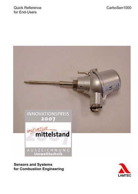
3 Technical Description3 Technical Description3.1 The SensorThe <strong>CarboSen1000</strong> is a sensor system <strong>for</strong> the detection of flammable gases such as CO, H 2or C x H y . In this manual, these gases are also referred to as CO equivalent (CO e ).The sensor system consists of the sensor and the sensor electronics. The unit, comprising thesensor element, sensor housing and sensor signal cable, <strong>for</strong>ms the sensor, which is used todetect the measured variable. The sensor electronics enable temperature compensation duringoperation, flexible control of the sensor and the acquisition of all sensor signals.The <strong>CarboSen1000</strong> 1000 is a high-resolution measuring system <strong>for</strong> the detection of small CO econcentrations in the range of 0 - 3000 ppm (ideally up to 1000 ppm). In the ST version, theelectronics are integrated in the head of the sensor.The <strong>CarboSen1000</strong> functions on the principle of solid-state electrolysis. The technology used<strong>for</strong> this method is well known and widely used in the <strong>for</strong>m of the lambda sensor. However, unlikethe lambda sensor, which measures oxygen on the basis of the Nernst principle, the<strong>CarboSen1000</strong> functions according to the Non-Nernst principle. By varying the geometry, materialand electrical wiring, sensors working according to the Non-Nernst principle can also detectother gases such as CO, H 2 , and HC.To operate the sensor, it first has to be heated to operating temperature. This is achieved bymeans of a heating structure, which is affixed to the back of the sensor element. The resistanceof the platinum heating spiral has a defined temperature dependence. This enables theoperating temperature of the sensor to be set. This temperature is 630°C and is set automaticallyby the electronics and kept constant during operation. To this aim, the electronics automaticallydetermine a cold resistance of 20°C when the sensor system is commissioned.The sensor temperature can be varied <strong>for</strong> special applications. For this purpose, the relevantparameters have to be reprogrammed. Upon customers’ request, this can be carried out eitherat LAMTEC or on site (with the appropriate programming unit). If the operating temperature ischanged, so is the sensor characteristic. Increasing the temperature of the sensor results inreduced sensitivity, i.e. the sensor is less sensitive to CO e and the curve is flatter. The sensordynamics become faster, i.e. the response and decay times are accelerated.Fig. 3-1 Principle of the Non-Nernst sensor9
3 Technical Description3.2 Sensor Types and VersionsFig. 3-2 <strong>CarboSen1000</strong>1.000 ST with electronics in adapter housingFig. 3-3 <strong>CarboSen1000</strong>1.000 in clip housingFig. 3-4 <strong>CarboSen1000</strong>1.000 in rod housing10
3 Technical Description3.3 Sensor Electronics XC 164The microprocessor-controlled sensor electronics per<strong>for</strong>m the following functions in the system:• Heating the sensor and regulating the heater spiral to a constant heating resistance• Acquisition of the sensor voltages in mV• Conversion of measured sensor voltages and output to the analogue output (0/4-20mA)• Monitoring of both sensor voltages• Checking the analogue outputs• Output of measured values on USB CAN bus.The electronics have a power supply of 13V to 30V DC. Ideally with 24V / 1.5A.The standard configuration CO e is calculated from the sensor voltage and would be given inthe analogue output. Internally, both sensor signals are compared and checked on the basisof the following failure criteria (standard parameterisation):• Difference greater than 25mV, or• Difference greater than 25% from the current measured value.Fig. 3-5 Electronics with adapter housingFig. 3-6 Electronics <strong>for</strong> top hat rail mounting11
4 Installation and Commissioning4 Installation and Commissioning4.1 General In<strong>for</strong>mationMeasuring temperature:Type NT and clip housing 150°CType HT: 150°.... 400°CPer<strong>for</strong>mance and average lifespan <strong>for</strong> the following fuel:Blue flame burner (oil / gas):approx. 3 yearsWood combustion (neat stock wood / pellets): approx. 2 yearsOther fuel <strong>for</strong> wood combustion, according to < 1 yearcontamination concentration (e.g. woodchip, bark)Measuring point:The measuring point should have the complete mixture of representativeexhaust gasesMounting position:The mounting position of the sensor should be as perpendicularas possible to the connection cable or the connection head, atleast 10° over the horizontal level.4.2 Installation4.2.1 CarboSen1.000STThe sensor system with <strong>CarboSen1000</strong> ST electronics is set up and connected as describedin the following steps:• Connect the 4-pin plug (power supply (13V-30V) / analogue output). Make sure that thepower supply is switched off. Connection cable schielded, max. cable cross section 1mm 2 .The maximum cable length of 100m should not be exceeded.• If required, connect to LAMTEC SYSTEM BUS 5-pin, <strong>for</strong> connection of LSB-Modules and/or programming unit. Connection cable schielded, max. cable cross section 1mm 2 .The maximum cable length of 100m should not be exceeded.• After the plug has been connected, the power supply can be switched on.First, the sensor is heated to operating temperature. This process is complete when only thegreen LED is continuously lit. This cold start phase then lasts approximately 2min.Plug A1Round plug connector, 4-pin• Pin 1 Supply voltage 0V• Pin 2 Supply voltage 24VDC• Pin 3 Analogue output -• Pin 4 Analogue output +12
4 Installation and CommissioningPlug A2Round plug connector, 5-pin• Pin 1 24VDC output + (only <strong>for</strong> programming unit)• Pin 2 24VDC output - (only <strong>for</strong> programming unit)• Pin 3 CAN-GND (LSB)• Pin 4 CAN-L (LSB)• Pin 5 CAN-H (LSB)4.2.2 CarboSen ST and in Clip- and Rod HousingThe microprocessor-controlled sensor electronics per<strong>for</strong>m the following functions in the system:• Put the electronics on a top hat rail and make sure it does not slip in both directions.• Connect the analogue output .• Connect the power supply (13 V – 30 V). This is to ensure that the power supply is disconnected.• Connect the CAN-Busses (only necessary in servicing). After a proper connection, thepower supply can be turned on. Some of the LEDs may flash or blinks (<strong>for</strong> detailed description,see Chapter). Remark: it is normal <strong>for</strong> the electronics to show a fault indication,as there are no sensors connected. To connect the sensors, the following steps should beper<strong>for</strong>med:• Switch on the power supply.• Hold <strong>for</strong> 60s. During this time, the electronics would secure that no sensors are connected,the green LED would blink with a frequency of 0.25 Hz.• Insert and screw the sensor plug into the DIN-socket. The heating resistance would be defined.Thegreen LED blinks with a frequency of 4 Hz.• Please hold until the nominal operation. The green LED blinks with a frequency of 1 Hz.CAUTION!For an accurate determination of heating resistance, it is necessary that the sensor is cooleddown to room temperature (20°C) and no air supply air is exposed.For the determination of cold resistance, a short heat impulse would be applied to the sensorand the resistance would be measured. This measurement should be carried out in intervalsof 16 seconds until either three successive measurements occur in a tolerance band of 0.1 or ten measurements are completed. The average of the last three values is used to calculatethe resistance at 20°C by applying a factor. This determination of the cold resistance shouldbe completed in 90 seconds.The determined value of the heating resistance at 20°C would be saved in the electronics andmust be taken into consideration on the first commissioning. In subsequent operations, theelectronics can be turned on with the plugged sensor.After the resistance is saved, the heating up process of the sensors begins. This heating upprocess is based on the preset target temperature. The measurements of the ohmic internalresistance of the alternating current R ki would be determined between the electrodes. This determinationis completed either when three successive measurements occur within the toleranceband or when ten measurements are completed. As standard parameter, the average ofthe last three measurements would be saved and used <strong>for</strong> temperature stabilisation.Should re-determination of the resistance become a necessity; the sensor should be removedfrom the activated electronics. After 30 seconds, the electronics would detect the absence ofthe probe and signal a fault. Re-plugging of the sensor should only take place when the roomtemperature is cooled down.13
4 Installation and Commissioning4.3 Installations InstructionsIf the electronics are connected to the attached sensor, the saved resistance R ki in the memorywould be drawn up <strong>for</strong> heating control. The cold start phase takes approx. 30s. During theoperation, this resistance would be monitored. Furthermore, the heating resistance of theheater would be verified permanently. If this exceeds 35, a circuit failure would be assumedand a failure message would be shown.Fig. 4-1 X164 with connection diagram4.3.1 CarboSen ST and in Clip- and Rod HousingNo. General terms Assignments1 Power supply PE2 0V3 24V DC4 Analogue output 1 Screen5 Minus6 Plus7 Analogue output 2 Screen8(only with 2-board type)Minus9 Plus10 LAMTEC SYSTEM BUS Screen11 CAN-High12 CAN-Low13 CAN-GNDDrill a bore hole (the size of the bore hole depends on the size of the sensor bracket) on theflue gas duct and attach the sensor bracket to the flue gas duct.For a better flow of the housing, older versions as well as special versions should have twobore holes, which are opposite each other and with a flow direction of 90°C as possible.Fig. 4-2 <strong>CarboSen1000</strong>ST14
4 Installation and Commissioning4.3.2 CarboSen in Clip HousingDrill a boring/hole with a diameter of 11.5mm in the exhaust gas duct and plug in the<strong>CarboSen1000</strong> as far as it will go until a stop.NOTICE!<strong>CarboSen1000</strong> should be installed directly be<strong>for</strong>e commissioning!In an installed condition, the <strong>CarboSen1000</strong> should always be heated up. This is to avoid themoisture from setting into the measuring cell, which could lead to measurement error and deteriorationof the <strong>CarboSen1000</strong>.CAUTION!When setting up the openings, there could be falling parts caused by damages. Make sure theparts to be isolated are secured by wire tack-weld!Take appropriate safety precautions against emerging hot, explosive or health-damaging exhaustgases.CAUTION!The mounting position of the sensor should be as perpendicular as possible to the connectioncable or connection head, at least 10° above the horizontal line.A mounting position that falls below the horizontal limit can damage the sensor.4.4 Programming unit <strong>for</strong> CarboSen 658R0932 (Option)Fig. 4-3 Programming unit15
4 Installation and Commissioning4.4.1 Brief DescriptionThe operating unit consists of a configuration software and an operational guide software,which were specially designed <strong>for</strong> <strong>CarboSen1000</strong> ST.The operator will be given the inputs and activities in a sequence, which will be per<strong>for</strong>med.The operating unit runs during the first commissioning of <strong>CarboSen1000</strong> ST as well as duringindividual sections of the configuration possibilities. In the following document, the individualsteps of commissioning and configuration is described with the help of the display window ofthe programming unit.NOTICE!Software version of <strong>CarboSen1000</strong> ST <strong>for</strong> commissioning and configuration:at least V1_10 or higher.Update <strong>CarboSen1000</strong> ST Software, where applicable!• Programming unit, including connection cable Item Number 658 R 0932• Power supply voltage 24VDC / 2,5W (from <strong>CarboSen1000</strong> ST)• Protection class according to EN 60529IP404.4.2 Connection to the CarboSen STPlease connect the programming unit to the <strong>CarboSen1000</strong> using the connection cable andthe adapter cable provided. The power supply takes place from <strong>CarboSen1000</strong> ST.Fig. 4-4 Connection between <strong>CarboSen1000</strong> and the programming unit16
5 Menu5 Menu5.1 Switching on the Operating UnitThe display of the programming unit shows the following starting sequence after the systemis switched on:The display shows the start window.The starting sequence runs automatically.The display shows the version (an examplehere) of the loaded software.The starting sequence runs automatically..Program loading.Please confirm the question. If youwould like to change the sensor orthe control parameter(s), youshould proceed with the installationroutine.Alternatively, you can acknowledgethe question and skip theinstallation routine.For an accurate execution of the installation routine, the <strong>CarboSen1000</strong> must be cooled downto approximately 20°C (take note of cooling time). In addition, the sensor is not allowed to beexposed to supply air.17
5 MenuAfter completion of the installation routine orrather after skipping the installation routine,the sensor would be heated up to operatingtemperature.Please use the , keys to switchto the selection menu.5.2 Main MenuFig. 5-1 Main Menu1 preset reference characteristic line <strong>for</strong> fuels, Release Level2 CO e -Display in ppm (with calculated characteristic curve)3 Sensor voltage of electrode 14 Sensor voltage of electrode 25 Open window6 Help7 Menu8 Switch to another window (Measuring Values -> Limit Values -> LSB) Remote - Shutdown Help Menu Switch to another windowBack one level be<strong>for</strong>eRelease Level 0 - no password necessaryRelease Level = a digit after the key icon shows that password entry is needed18
5 Menu5.2.1 Help WindowTo switch to the Help window, press the F2 key. The Help window will pop-up to your currentdisplay window.F1 fault-RESETF2 Open HelpF3 Switch to menu selectionF4 switch to the following menu windowThe parameter details correlate to theparameter from the previous window whichwas used to call the Help window.5.3 Menu SelectionPlease use the , key to switch to the selection menu.The following sub-menu are available <strong>for</strong> selection in the release level 0:Password Input Language Actual measurement CO e -Curves Fault History Parameter Configuration ContrastIn order to make changes, you must find yourselves in one of the following release levels. Yourrelease level shall determine if you are allowed to change parameters or if you are only allowedto retrieve them.Release Level 0 : ServiceRelease Level 1 : CustomerThe description of the release levels 0 and 1 can be found in the next chapters.Use the and keys to navigate.19
5 Menu5.3.1 Password EntryPassword input with 3, 5,7, and 9 keys (upward count) and 2, 4, 6 and 8 keys (downward count).Please confirm password with key.5.3.2 Select LanguagePlease use the and keys to select thelanguage of your choice.Please confirm password with key.5.3.3 MeasurementPlease use the and keys to navigate. The displayed values cannot be changed. (RL0 = Release Level 0, RL1 = Release Level 1).20
5 Menu5.3.4 Control ValuesPlease use the and keys to navigate. The displayed values cannot be changed. Youcan only read these entries, when you are categorized under the corresponding release level(Release Level 1).21
5 Menu5.3.5 Configuration SensorPlease use the and to navigate. The displayed value cannot be changed. Please confirmthe entry with key. You can only change the values, when you are categorized underthe corresponding release level.(RL0 = Release Level 0, RL1 = Release Level 1)Smooth start-up:The value that you entered here would be defined by the time frame as a value where the heatingpower would raise from 0 to the setpoint.WARNING!Values smaller than 30 sec are critical!You could damage the heating structure, if you enter values smaller than 30 sec.Sensor type:Type A = Clip housingType C = Rod housing / <strong>CarboSen1000</strong> STNOTICE!The false selection of sensor type would affect the heating control.22
5 Menu5.3.6 COe CurvesPlease use the and keys to navigate. The displayed values cannot be changed.Please confirm the entry with key. You can only change the values, when you are catego-23
5 Menurised under the corresponding release level.(RL0 = Release Level 0, RL1 = Release Level 1)Calibration:Please activate the device <strong>for</strong> selection of fuel characteristic line. With the activated device,you could switch between fuel input 0 and fuel input 1.Fuel Input 0 / Fuel Input 1:Please select the characteristic line <strong>for</strong> sensor voltage conversion (fuel input 1 as well as fuelinput 2).A false setting would lead to false values.Default = Factory characteristic lineCurve selection:You can use this selection, when you have not used any control system <strong>for</strong> fuel input 0.Custom curve:Please post a maximum of 10 points <strong>for</strong> the programming of a customised curve. The pointsmust be numerically sorted (ascending/descending). If the values are not numerically sorted,this would lead to a false display of CO e -values.24
5 Menu5.3.7 LSB Configuration25
5 Menu5.3.8 Parameter ConfigurationPlease use the and keys to navigate. The displayed values cannot be changed.Please confirm the entry with key. You can only change the values, when you are categorisedunder the corresponding release level.(RL0 = Release Level 0, RL1 = Release Level 1)LSB-Address:Please set the address of your LSB module(s) here. A false entry would lead to a communicationfailure to the LSB module.Value range:Please set the value range <strong>for</strong> analogue output to 0...20mA or 4...20mA.0mA would generate an error message in the value range of 4...20mA.Measurement Values LSBAA2 - LSBAA5:Please set the measurement of which the sensor should emit in the analogue output 2-5.Threshold 1:Please set the thresholds <strong>for</strong> digital output; when the relay opens and closes respectively.Reset threshold:Please select how the limit values should be set back to its default status.Please use the and keys to navigate. The displayed values cannot be changed.Please confirm the entry with key. You can only change the values, when you are categorisedunder the corresponding release level.Read and write dataset:You can read and write set of parameters through the dataset from the device.26
5 MenuNOTICE!You can upload import parameters in sets only. Individual parameters cannot be uploaded orimported.5.3.9 ContrastPlease use the key <strong>for</strong> the setting of thecontrast. To set a value lower than the displayedvalue, you need to increase the valueto its highest limit. By exceeding the upperlimit, the display would be set back to thevalue which is the lowest limit value.27
6 Operation6 Operation6.1 Operation / Measurement Value Display6.1.1 Operation6.1.2 Measurement Value• via programming unit (optional)6.1.3 Status SignalsProbe voltage-100…+900 mV, transmission via analogue output 1 (0/4...20mA)ST-Tap version: Pin3 and Pin4 of circular plug.Electronic XC164-Tap: Terminal 4 and Terminal 5Other measurement values can be transmitted via an analogue output module (optional).Transmission via digital output module (optional)6.2 General Instructions <strong>for</strong> Operation6.2.1 Operational Failure, Switching On and Off6.2.2 Liquid PurificationWith a longer period of failure, from approximately 3 months onwards, we recommend themeasurement to be shut down. In order to avoid the probe sensor from being damaged, theprobe sensor must be dismantledWe recommend you to leave the measurement to run during periods of short failure.You are allowed to per<strong>for</strong>m a wet cleaning of the boiler, when you dismantle the probe be<strong>for</strong>ehand.If you per<strong>for</strong>m a wet cleaning to an installed probe, this could lead to damaging of theprobe. An error free operation is then no longer possible.CAUTION!For the wet cleaning, the probe must be dismantled by all means. A wet cleaning of an installedprobe will lead to damaging of the probe.28
6 Operation6.2.3 Per<strong>for</strong>ming Sensor Change-OverIf the sensor is still warmer than ambienttemperature after 5 min, then you should waituntil the sensor is cooler and not warmerthan the ambient temperature anymore.Due to safety reasons, you should closedown any other running programs or activitiesduring the installation.29
6 Operation6.2.4 Calibration of the COe-CurvesYou need release level 2 to do these settings.Insert your password <strong>for</strong> release level 2. You willreceive this password only after consulting LAMTECsupport.Phone: +49 (0) 6227 6052 33E-mail: support@<strong>lamtec</strong>.deCO e / ppm shows the actual CO e value (read only)Scale factor - This scaling factor will be multiplied bathe CO e value.After you have inserted and acknowledged the scalingfactor, the display shows the changes CO e value inppm, corresponding to the factor you have inserted.Autom. Offset sets the offset to 0.Offset = display value30
6 Operation6.2.5 Initiate the Cold Resistance Determination31
6 OperationIf you want to start the definition of the cold resistance, proceed as described in chapter 5.1and confirm a change of the sensor or start from the main menu with (see chapter 5.2).1)WARNING!Watch the sensor’s temperature!Proceed the definition of the cold resistance only, if your sensor has cooled down to ambienttemperature.If the sensor is too warm, you will get a wrong result and the sensor may be damaged.Let the sensor cool down <strong>for</strong> at least 5 min. A longer cool down period will be better.Check the your sensor’s temperature.2)NOTICE!Protect your sensor from air drought.If your sensor is exposed to air draught during the definition of the cold resistance, this mayfalsify the result or the measurement fails.Take care <strong>for</strong> a air draught free environment.Press keyto end the definition of the cold resistance. The installation starts.32
6 Operation6.2.6 Changing the Sensor Temperature (RI)You need release level 2 to do these settings.Insert your password <strong>for</strong> release level 2. You will getthis password after consulting with LAMTEC support.Phone: +49 (0) 6227 6052 33E-mail: support@<strong>lamtec</strong>.dethe bigger the factor the higher the temperaturethe smaller the factor the lower the temperatureThe steps <strong>for</strong> changing the factor may have amaximum of 0,1.Mind the following limit!Never exceed the maximum factor of 2,8.If you exceed the maximum this may disturbthe sensor or minimises it’s lifetime enormusly.If the factor is smaller than 2,4, the sensor istoo cold. This may lead to a false measurementand to a too high offset.Change with key into the main menu and start the installation (refer to chapter 6.2.5 Initiatethe Cold Resistance Determination).33
6 Operation6.2.7 Analogue Output 1You need release level 1 to do these settings.Insert the password <strong>for</strong> release level 1.If you have <strong>for</strong>gottenyour password, contact LAMTEC support.Phone: +49 (0) 6227 6052 33E-mail: support@<strong>lamtec</strong>.deIn analogue output 1 choose, which value analogueoutput 1 shall output.Meas. Usen = average sensor voltageMeas. Usen 1 = single voltage, <strong>for</strong> calculating the averagesensor voltageMeas. Usen 2 = single voltage, <strong>for</strong> calculating the averagesensor voltageHeating power = the heater’s wattageR-Heater = the heater’s resistancePulse-width = the heater’s pulse-widthRki = ceramic inner resistanceCOe = calculated CO e value of the preset characteristiccurve34
6 Operation6.2.8 Setting the Limit ValuesYou need release level 1 to do this settings.Insert your password <strong>for</strong> release level1. If you <strong>for</strong>gotyour password <strong>for</strong> this release level, contact LAMTECsupport.Phone: +49 (0) 6227 6052 33E-mail: support@<strong>lamtec</strong>.dechoose in the LSB menu, wether you want to set limitvalue 1, limit value 2 or the way to reset the limit value.Activate voltage (sensor voltage) or COe (calculatedvalue) as the limit value.If you choose CO e , you must calibrate thecharacteristic curve regularly. You must dothis with a reference device at least at commissioning.Release time = the limit value is triggered after thisperiodMaximum = limit value maximum of the measurementvalueMinimum = minimum limit value of the measurementvalueTH1 min active = lower threshold activeTH2 max active = upper threshold activeManual reset = reset by pressing a keyAutomatic reset = As soon as the value leaves thethreshold, a reset will be triggered automatically.Confirmation = A reset will be triggered automatically,but you have to confirm the reset additionally.35
7 Service and Maintenance7 Service and Maintenance7.1 Exchanging the Sensor7.1.1 CarboSen ST and in Clip- and Rod Housing7.1.2 CarboSen1.000STFor this type of <strong>CarboSen1000</strong>, the complete probe must be exchanged.For repairing the sensor system <strong>CarboSen1000</strong> ST, it is possible to exchange the whole sensor.For the exchange, the following spare parts numbers should be provided:Spare partsArt. No.Description658 R 0013 Replacement sensor <strong>for</strong> 658 R 0010, 150mm (HT-Type*)658 R 0022 Replacement sensor <strong>for</strong> 658 R 0012, 250mm658 R 0031 Replacement sensor <strong>for</strong> 658 R 0030, 150mm(NT-Type*)658 R 0105 Replacement electronics XC164 in <strong>CarboSen1000</strong> ST* T – high temperature (150°C to 400°C exhaust gas temperature), T – low temperature (up to 150°C exhaust gas temperature)Please follow the instructions step by step to exchange the sensor:• Disconnect both DIN-plugs (4-pin / 5-pin) from the sensor system.• Open the cover plate and remove the 6-pin plug from the board.• Screw out the old sensor from the electronics. Please make sure that the cable does nothang on the electronic board and there<strong>for</strong>e not damaged.• Screw in the new sensor with the new copper seal ring and fix it. Please do not plug the 6-pin connector to the electronics at this step!• Attach and screw the DIN-plug.• Connect the sensor system to the power supply and hold <strong>for</strong> 2 minutes (red LED flashesand green LED flash at 4 Hz)• Plug the 6-pin connector to the electronics. The determination of resistance would be initiated.The sensor has to be outside high air flow and it has to be at ambient room temperature(approx. 20°C). When it comes to the end of this process, the resistance would besaved.• Hold until the green LED flashes (frequency 1 Hz)• Close the housing of the electronics. Please keep attention to the connector cable of thesensor (do not clamp it!)• Exchange the label on the housing or change the serial number of the sensor on the oldlabel.The sensor system is now ready <strong>for</strong> use.36
8 Accessories8 Accessories8.1 Programming Unit8.1.1 Panel Installation option• Panel installation frame <strong>for</strong> programming unitItem no. 663 R 0932T• Protection class according to EN 60529IP54Fig. 8-1 Programming unit in panelinstallation frameFig. 8-2 Panel cutout 105 x 18337
8 Accessories8.2 Analogue Output Module with address 19 <strong>for</strong> Display of Measurement SignalsFig. 8-3 analogue output module• 4 analogue output 0...10VDC (non-floating) or item no. 663 R 4025or• 4 analogue output (non-floating)item no. 663 R 4029• <strong>for</strong> producing:– average sensor voltage– sensor voltage 1– sensor voltage 2– heating power– internal resistance of heating– pulse width heating– internal resistance of sensors– CO eAdjustable in parameter 810...825 of the <strong>CarboSen1000</strong> STNOTICE!Please check the accuracy of the preset module address!8.3 Digital Output Module with module address 03• 4 relay output 250 V, 6 A (floating) item no. 663 R 40275• Output 1 – Limit value 1Output 2 – Limit value 2Output 3 – not measuredOutput 4 - fault• Manually operated emergency menuSetting „1“ Output contact closed at all timesSetting „A“ Output contact switch over to LSBSetting „0“ Output contact opened at all timesFig. 8-4 digital output moduleNOTICE!Please check the accuracy of the preset module address!38
8 Accessories8.4 Digital Input Module with module address 11• 4 digital inputs 24V/DCThe inputs are executed with an input voltage of 24V/DCwith electrical isolation.Item no. 663 R 4028• Input 1 – RESET limit values 1 & 2Input 2 – not assignedInput 3 – start sensor testInput 4 – RESET fault / warning• Manually operated emergency menuSetting „1“ Input is HIGH at all timesSetting „A“ Input switches over contact from outsideSetting „0“ Input is LOW at all timesFig. 8-5 digital input moduleNOTICE!The input and output module can be mounted without any gap. After mounting 15 modules,the power supply should start externally.With more than 15 modules, the bypass plug would be overloaded and burn out.Please observe the fuse protection of the external power supply. Bear in mind that there is noline-side fuse available.NOTICE!Please check the accuracy of the preset module address!8.5 Power PackExt. power pack 230VAC/24VDC - 1.5A (35W) <strong>for</strong> power supply of <strong>CarboSen1000</strong> ST, the programmingunit and the module• Item no. 658 R 01095• Range of input voltage 85...264 VAC, 47...63 Hz• Typical current consumption 0.48A• Installing on mounting rail TS35• Operational temperature range -20...+60°C• Weight 270gr• Protection class IP 2039
8 AccessoriesFig. 8-6 Ext. Power Pack 230VAC/24VDC – 1,5A (35W) Type 658 R 01095Fig. 8-7 Dimensional diagram ext. Power Pack Type 658 R 0109540
9 Technical Data9 Technical DataElectronics:Sensor:Dimensions:Type STType XC164Supply voltage:Power consumptionElectronics and probeAnalogue output:Scaling of analogue output:111x111x87 mm³112x112x85 mm13-30VMax. 8W(without additional devices)(Sensor, up to 6W)0/4 - 20mA, 0mA = errorBurden 300 Ohm-100mV up to +900mVMeasurement principle:Measurement range:Cross-sensitivity:Response time t (sensor element):Temperature Field:Sensor temperature:Solid state electrolysis (Non Nernst)up to 3.000ppm CO/H 2H 2 OnoneTemperature very lowVolume flow rate very low
9 Technical Data* with an opened cover plate of 190 mmArt.No.L/mm658 R 0010 150658 R 0012 250658 R 0030 150Plug A1Round plug connector, 4-pin• Pin 1Power supply voltage 0V• Pin 2Power supply voltage 24VDC• Pin 3Analogue output –• Pin 4Analogue output +Plug A2Round plug connector, 5-pin• Pin 124VDC-output +• Pin 224VDC-output -• Pin 3CAN-GND (LSB)• Pin 4CAN-L (LSB)• Pin 5CAN-H (LSB)Connection cable schielded, max. cable cross section of 1mm 2 .Maximum cable length should not exceed 100m.42
10 Ordering In<strong>for</strong>mation10 Ordering In<strong>for</strong>mationAccessoriesProduct / TypeOrder No.Programming unit, <strong>for</strong> the setting of <strong>CarboSen1000</strong> parameters in sets (connection cable included) 658 R 0932Panel installation frame <strong>for</strong> programming unit663 R 0932TAnalogue output module 0...10 V with the address 19 663 R 4025Analogue output module 0...20 mA with the address 19 663 R 4029Digital output module with the address 03 663 R 4027Digital input module with the address 11 663 R 4028Ext. power pack 230 V AC / 24 V DC - 1.5A, <strong>for</strong> the power supply of <strong>CarboSen1000</strong> ST, the plug unit 658 R 0109and the moduleSpare PartsProduct / TypeOrder No.Replacement sensor 658 R 0010, 150mm 658 R 0013<strong>CarboSen1000</strong>10.000HT-ST-Mounting 150mm 658 R 0017<strong>CarboSen1000</strong>1.000HT-ST-Mounting 250mm 658 R 0018<strong>CarboSen1000</strong>10.000HT-ST-Mounting 250mm 658 R 0019Replacement sensor <strong>for</strong> 658 R 0030, 150mm 658 R 0031Replacement electronics XC164 on the head of <strong>CarboSen1000</strong> ST 658 R 0105Replacement connecting cable <strong>for</strong> the programming unit 663 R 0430Replacement adapter cable <strong>for</strong> the programming unit 658 R 0426Detailed explanation of termsDS Top coatHT High temperature (ceramic castings) 150°C - 400°CNT Low temperature (epoxy resin castings) < 150°CG Glass castingsST with electronics on the head43
11 FAQ11 FAQCan the sensor operate in condensed moisture?At present, there are two versions of the rod housing. The first type (NT) is designed <strong>for</strong> applicationsup to 150°C and can be operated under condensed moisture as long as the sensordoes not immerse into the condensation. The second type (HT) is designed <strong>for</strong> applications with a constant measuring temperature of150°C to 500°C. The clip housing is designed only <strong>for</strong> applications with ambient temperature up to 150°C.How should the sensor be installed?The best mounting position is upright, with the head / connection cable facing up. Should therebe a problem due to installation situation; the next best possible setting angle to choose fromis min 10° horizontally. An installation position below this horizontal level is to be avoided, becausethis could damage the sensor.What substances are considered to be harmful to <strong>CarboSen1000</strong>?Sulphur oxide, fluorine and chlorine compounds as well as silicon could be harmful to<strong>CarboSen1000</strong> and could cause a complete breakdown in extreme cases, depending on theconcentration. Also firm deposits on the sensor elements could affect the sensor characteristics, e.g. crystallisedsalt from condensation could interfere with the gas diffusion of the sensor.What are the effects of solid particles such as carbon and ash on the sensor?Carbon has no effect on the sensor and it does not contaminate the sensor. The sensor itselfhas a temperature of 630°C. There<strong>for</strong>e, carbon combustion occurs instantly at this ambienttemperature. Other solid particles in measuring gas such as ash would normally not end up inthe housing.Can I clean the sensor?Should it be necessary, the sensor housing can be wiped with a piece of dry cloth. Please beaware that the contaminated dirt should not be pressed against the plastic foil on the head ofthe sensor. Any kind of detergent or dissolver is not allowed in the cleaning the sensor.Does the temperature of the sensor drift?No. The sensor has a firm zero-point of ambient temperature, which can be given 0mV 5mV.What are the known effects of deterioration of the sensor?Some small inlet effects are known, which may occur during the first few hours of sensor operation.This effect could increase the sensitivity of the sensor. Deterioration effects such asdamage due to harmful substances depends very much on the type of substance used and itsconcentration (see above).What are the cross-sensitivity effects of <strong>CarboSen1000</strong>?<strong>CarboSen1000</strong> is a mixed potential sensor. Hence, it could detect all kinds of oxidisable, gaseoussubstance (CO e ), as well as those with different sensitivity. With the existence of multiplecomponents, this cannot be concluded selectively. Furthermore, the sensor voltage is dependent on the oxygen content in measuring gas. Thelower the oxygen content, the higher the sensor voltage while CO e being held constant. The <strong>CarboSen1000</strong> has no cross-sensitivity effects on H 2 0-vapour, CO 2 , inert gases.What are the effects of the sensor temperature on the sensor voltage?The sensor voltage is strongly temperature-dependent. The <strong>CarboSen1000</strong> operates in atemperature of 630°C. Possible operating temperature lies between 450°C and 700°C. As a44
11 FAQbasic principle, the lower the sensor temperature, the higher the sensitivity of CO e and there<strong>for</strong>esensor voltage increases while the composition of measuring gas is held constant.Can the sensor operate in condensed moisture?At present, there are two versions of the rod housing. The first type (NT) is designed <strong>for</strong> applicationsup to 150°C and can be operated under condensed moisture as long as the sensordoes not immerse into the condensation. The second type (HT) is designed <strong>for</strong> applications with a constant measuring temperature of150°C to 500°C. The clip housing is designed only <strong>for</strong> applications with ambient temperature up to 150°C.Why does the sensor voltage decrease at a given point although COe increases?The <strong>CarboSen1000</strong> requires a minimum level of oxygen, depending on the CO e concentration,to maintain the reaction kinetics of the electrodes. Should the oxygen level fall below theminimum level, the sensor voltage cannot be maintained and break altogether.Is COe of the <strong>CarboSen1000</strong> harmful to the oversaturation of the sensor?No. As soon as the composition of the measuring gas lies in the correct range, the sensorwould show the usual measurement procedure.How do I recognise an error message from the sensor system?The red LED flashes and the analogue output would be defined as 0mA.45
12 Error Detection and Measurements12 Error Detection and Measurements12.1 Green LEDs do not flashIn the following overview, known errors and their recognition features as well as possible causesof these errors are discussed.12.2 LED Status• Is the power supply connected and switched on properly?• Did the power supply fulfil the requirements (13-30V, at least 6W)?• Are the plugs attached to the board?• The red LED flashes: An error exists.• The yellow LED lights up: Heating phase.• The green LED flashes quickly with 4 Hz: Installation routine is running• The green LED flashes slowly with 0.25 Hz: There is no sensor connected or the sensoris defect.• The green LED Flashes normally with 1 Hz: A non-heating specific error exists.12.3 Fluctuating Sensor Voltage without Distinguishable PatternPossible errors are:• Rapidly changing conditions in measuring gas. The sensor has an extremely low responsetime.• External effect.• Due to the high-resistant short-circuited heating, there may be influence on the sensor’sside. There<strong>for</strong>e, it should be verified if the sensor is designed <strong>for</strong> high temperature (HT)and if it is able to operate in a condensed moisture. Sensor heated at 100°C <strong>for</strong> repeatedhours, where applicable.12.4 Constant Sensor Voltage, independent of Measuring Gas• Sensor voltage equals to null: sensor is defect or had totally lost its sensitivity• Sensor voltage is not equal to null: external effects, e.g. through the heating46
12 Error Detection and Measurements12.5 FaultsNo. Output text Cause of fault signal Remarks1 Heater defect maximum heating power is exceeded would be restrained during the heatingphase2 Heater defect Connection to other channels aborted(timeout expired)3 Analogue output defect an error occur during initialisation ofthe analogue output4 Sensor voltage beyondthe limits5 U sen difference toohigh12.6 Warningsone OR both sensor voltages beyond-30 to 700mVmaximum allowable voltage differencebetween the electrodes is exceeded.sensor may be fine but the control isnot workingno measurement value from analogueoutputnot implemented yetwould be restrained during the heatingphase; warning when it is 1-channel,fault message when it is 2-channelsNo. Output text Cause of fault signal Remarks101 Ph max achieved maximum heating power is exceeded would be restrained during the heatingphasePh min achieved, overheatedambience103 Heating resistancebeyond the limits104 U sen difference toohigh105 Ceramic resistancebeyond the limits106 Deviation of R h fromsetpoint value107 Sensor resistancedriftsfalling below minimum heating powerfixed cold resistance falls beyond specificlimitsmaximum allowable voltage differencebetween the electrodes is exceededfixed ceramic resistance falls beyondspecific limitsthe current measured value R h deviatestoo far away from the saved setpointvaluethe resistance values changes significantly(measured over a long period oftime)would be restrained during the heatingphaseSensor would be operated with defaultvalue R kaltwould be restrained during the heatingphase; warning when it is 1-channel,fault message when it is 2-channelsSensor would be operated with defaultvalue R kalt(only with R ki -Control)long-run testing of the discarded triple(R h ,R ki ,U s ), Triple would be relocatedback after every installation routine.47
13 Support13 SupportLAMTEC Mess- und Regeltechnik für Feuerungen GmbH & Co. KGWiesenstraße 669190 Walldorfsupport@<strong>lamtec</strong>.deTel.: +49 6227 – 6052-33 Fax: +49 6227 – 6052-5748
14 Declaration of Con<strong>for</strong>mity14 Declaration of Con<strong>for</strong>mityMonth / Year:Manufacturer:Address:Product name::.................................December ../...2005..............................LAMTEC Meß- und Regeltechnikfür Feuerungen GmbH & Co KG..............................................................................Wiesenstraße 6, D-69160 Walldorf..............................................................................<strong>CarboSen1000</strong>Type 658 R 0106 /R 0107 /R 0010...............................................................................................................................................................The named product con<strong>for</strong>ms to the stipulations of the following European Directives:Number Text89/336/EWG Electromagnetic Compatibility73/23/EWG Low Voltage DirectiveMore in<strong>for</strong>mation about compliance with these Directives is contained in the annexDisplay of CE-Marking:Place, DateYesWalldorf, 16 December 2005Legally binding signature:The annexes <strong>for</strong>m part of this Declaration.This Declaration certifies compliance with the above-mentioned Directives, but contains no assurances in respect of specifications.The safety in<strong>for</strong>mation in the supplied production documentation must be read and observed.49
14 Declaration of Con<strong>for</strong>mityMonth / year:Appendixto EC Declaration of Con<strong>for</strong>mityor EC Manufacturer’s Declaration:.................................December../...2005..............................Product name: <strong>CarboSen1000</strong> Type 658 R 0106 /R 0107 /R 0010..........................................................................................................................................................The adherence of the product named above with the stipulations of the above-mentioned Directives is proven by itscompliance with the following standards and regulations:Harmonised European Standards:<strong>Reference</strong>-NumberDIN EN61326, issue 2004-05(IEC 61326:1997 + IEC 61326-1/A1:1998 + IEC 61326-1/A2:2000 + Appendices E & F to IEC61326:2002 + Corrigendum:2002); German version EN 61326:1997 + EN 61326/A1:1998 +EN 61326/A2:2001 + EN 61326/A3:2003The following basic standards have been adhered to:Interference Immunity:DIN EN 61000-4-2DIN EN 61000-4-3DIN EN 61000-4-4DIN EN 61000-4-5DIN EN 61000-4-6Emitted Immunity:DIN EN 55011 Kl. BElectrical Safety:DIN EN 61010-150
14 Declaration of Con<strong>for</strong>mity51
LAMTEC Meß- und Regeltechnikfür Feuerungen GmbH & Co KGWiesenstraße 6D-69190 WalldorfTelefon (+49) 06227 / 6052-0Telefax (+49) 06227 / 6052-5Internet: http://www.<strong>lamtec</strong>.deemail: info@<strong>lamtec</strong>.deLAMTEC Leipzig GmbH & Co KGSchlesierstraße 55D-04299 LeipzigTelefon (+49) 0341 / 863294-00Telefax (+49) 0341 / 863294-10Überreicht durch:Druckschrift-Nr. DLT5813-10-aEN-001Printed in Germany