Technical Data Lambda-Transmitter LT 1 - lamtec
Technical Data Lambda-Transmitter LT 1 - lamtec
Technical Data Lambda-Transmitter LT 1 - lamtec
- No tags were found...

You also want an ePaper? Increase the reach of your titles
YUMPU automatically turns print PDFs into web optimized ePapers that Google loves.
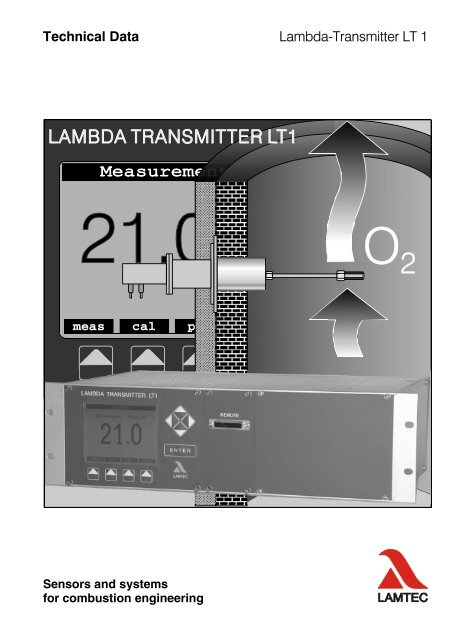
System overview<strong>Lambda</strong>-<strong>Transmitter</strong> <strong>LT</strong> 1The <strong>LT</strong> 1 <strong>Lambda</strong> transmitter is a universal, microprocessor-based O 2 measuringinstrument for the direct measurement of O 2 concentration in exhaust gases from oiland gas combustion facilities in the super-stoichiometric domain (l>1), in conjunctionwith the LS 1 <strong>Lambda</strong> probe.For the collection of combustible gas components (CO/H 2 ) the Combination probe KS1 can be connected as an option.• - in combustion exhaust gases• - in industrial waste gases• - in furnace atmospheres• - in process gasesAdvantages:Linear probe signal (direct current [mA]) with fixed physical zero pointNo special calibration gases required, automatic calibration with ambient air(21% by vol. O 2 )Measuring accuracy better than 0.2 vol.% O 2 over the entire measuring range0…21 vol.% O 2No gas purification necessaryNo reference gas requiredSettling time
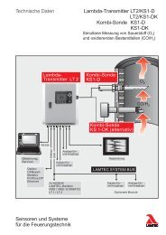
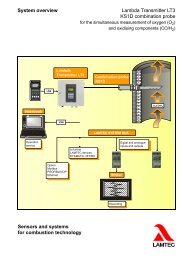
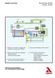
System overview<strong>Lambda</strong>-<strong>Transmitter</strong> <strong>LT</strong> 1<strong>Lambda</strong>-<strong>Transmitter</strong> <strong>LT</strong> 1<strong>Lambda</strong>-Probe LS 1Combination-Probe KS 1<strong>Lambda</strong>-<strong>Transmitter</strong> <strong>LT</strong>2 / KS1(optional)RS 232operationand serviceOption:CANopenModbusProfibus DPEthernetCAN, RS 422analogeuin- andoutputsdigitale inandoutputsLAMTEC SYSTEM BUSrecording
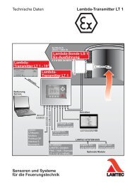
System overview<strong>Lambda</strong>-<strong>Transmitter</strong> <strong>LT</strong> 1<strong>LT</strong> 1 <strong>Lambda</strong> transmitter: input/output modulesOperating mode/service displayMultifunctionkeyMaintenance switchDisplay andoperating unit<strong>LT</strong> 2<strong>Lambda</strong> transmitterOEM versionLS 1<strong>Lambda</strong> probeKS 1combined probeSEA filterheatingMEVheatingProfibusInterbus-SCANopenModbusCalibration unitPressure sensorRS 232OperationandserviceMonitor output0 … 2.55 V DCLAMTEC SYSTEM BUS(CAN-BUS)orRS 422Test gasactuationHousingheating4 analogue outputs1x standard 3x optionalfreely configurableFull version4 analogue inputsfreelyconfigurable7 digital outputs1 relay6 open collectors8 digital inputsfreelyconfigurableStandardOptional
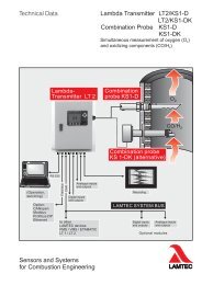
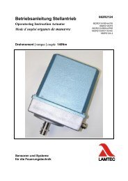
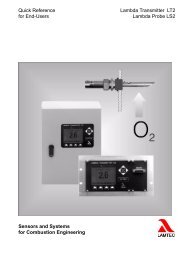
System components<strong>Lambda</strong>-<strong>Transmitter</strong> <strong>LT</strong> 1Basic construction with integral pump and calibration device for under-roof installationCalibrating gas connectionPressure sensorMeasured gas1 Probe installation fitting (SEA)No. 6 55 R 0083...R 11832 <strong>Lambda</strong> Probe LS 1No. 6 50 R 0031...R 0039Measured-gasreturn with blindclosure plugPressure sensorCalibrating gasconnection3 Gas extraction device (MEV) with extraction filtere.g. 1000 mm long No. 6 55 R 0027matching protective tube No. 6 55 R 0620PG screw connections (cable glands)4 Mating flangeNo. 6 55 R 0183 / R 01855 Insulation for LS 1 7 Flange seal, BAS greenNo. 6 57 P 0100 No. 6 50 P 42096 <strong>Lambda</strong> <strong>Transmitter</strong> <strong>LT</strong> 1 with integral measured 8 Indictor and control unit (option)gas pump and automatic calibration device (option) No. 6 57 R 0800No. 6 57 R 0020...R 0025 and 6 57 R 0800If the distance between the <strong>Lambda</strong> Probe LS 1 and the <strong>Lambda</strong> <strong>Transmitter</strong> <strong>LT</strong> 1> 10 m, it is recommended to provide a probe connection box (SAK) with themeasured-gas pump and, if necessary, with the automatic calibration device (option),close to the probe.For open-air installation, a transmitter protection box is also necessary for weatherprotection.Basic construction of <strong>LT</strong> 1 / LS 1 with external pump and calibration deviceMax. 400 °CIf the temperature of the measured gasis higher, the SEA must be set back further.Flue gas ductPressure sensor1 <strong>Lambda</strong> Probe LS 1No. 6 50 R 0031...R 00392 Gas extraction device (MEV) withextraction filter e.g. 1000 mm longNo. 6 55 R 0027matching protective tubeNo. 6 55 R 06203 Probe installation fitting (SEA)No. 6 55 R 0083 / R 1183Measured gasMeasured-gasreturnCalibrating gasconnectionPressure sensor connectionCalibrating gas supply<strong>Transmitter</strong> protection box,essential for open-air installation4 Insulation for LS 1 and SEANo. 6 57 P 01005 Probe connection box (SAK)No. 6 57 R 00136 <strong>Lambda</strong> <strong>Transmitter</strong> <strong>LT</strong> 1,external measured-gas pumpNo. 6 57 R 0021 / R 00267 Indicator and control unit (option)No. 6 57 R 0830Probe connection boxwith measured-gas pump,calibration deviceLAMBDA-TRANSMITTER <strong>LT</strong> 1Pump, externalCondensatecollector8 <strong>Transmitter</strong> protection box (option)No. 6 55 R 00879 Mating flangeNo. 6 55 R 0180 / R 0187Temperature of measured gas:> water or acid dew point, up to 700 °C, up to 1400°C (optional)
Measuring Principle<strong>Lambda</strong>-<strong>Transmitter</strong> <strong>LT</strong> 1Measuring principleO 2 concentration is continuously measured by the LS 1 <strong>Lambda</strong> probe (see separatepublication D<strong>LT</strong>6061).A small quantity of gas (approx. 0.5 l/h) is drawn directly from the measured gasthrough a capillary tube.A 7-wire plugged cable and a Teflon hose connect the LS 1 probe to the <strong>LT</strong> 1 <strong>Lambda</strong>transmitter.The probe's signal is analysed in the <strong>LT</strong> 1 <strong>Lambda</strong> transmitter, using the latestmicroprocessor technology. A serial interface, a monitor output0…2.55 V DC = 0…25.5 vol. % O 2 , up to 4 analogue outputs0/4…20 mA, 0…10 V and up to 7 digital outputs are available to output the measuredvalues and operating conditions.Internal LEDs provide operational information and indicate any system faults identifiedby the diagnostic functions.The <strong>LT</strong> 1 <strong>Lambda</strong> transmitter is provided with the following functions:• Automatic testing and calibration of the LS 1 probe against the ambient air.• Automatic ageing compensation of the ZrO 2 cell through determination of the cell'sinternal resistance and adjustment of the heater output.• Compensation for the effect of gas composition on gas flow through in highlyunbalanced measured gases, such as flue gas after wet scrubber or in vapoursresulting from fluctuating sound velocity and density, compared with conditionsduring calibration (air).• Intermittent gas pump with automatic calculation of optimum pump running time.Optional long-life mode with limited measuring accuracy.• Intelligent, optionally automatic cold-start delay, adjustable between5…120 minutes.• Integral maintenance switch.• LAMTEC SYSTEM BUS for direct coupling to the LAMTEC linked burner controlsystems VMS / FMS / ETAMATIC, for O2 optimisation and <strong>LT</strong>2 Ks1 for thedetection of nonburned CO/H 2 in waste combustion gases shown as COequivalent(COe)• A RS 422 interface is also available as an alternative to the LAMTEC SYSTEMBUS, for coupling to the customer's systems.• In addition, a RS 232 interface is available for PC-based remote control inconjunction with the (optional) service and diagnostic software.
Options• Display and operating unit• Automatic calibration unit for fully automated testing and calibration of theinstalled LS 1 <strong>Lambda</strong> probe when the system operates with ambient air;alternatively via an integral pump or pneumatically.• Portable calibration device for connection to <strong>LT</strong> 1• Test gas actuation (1…4 test gases) for checking the calibration(EPA standard).• Pressure compensation of the measured value;pressure range 800…1200 mbar• Temperature compensation of the measured value• Fine draught measurement•(1) Measurement of flue gas and intake air temperature, and calculation ofcombustion efficiency•(1) Calculation of CO 2 concentration, fuel-referenced, derived from themeasured O 2 value and the CO 2 -max value•(1) Load-dependent and fuel-specific boundary values / boundary curves• KS 1 combined probe for the detection of combustible components (CO/H 2 )• Electric heating of the gas extraction device and the sintered metal prefilter•(1) 1…3 additional analogue outputs, max. 2 floating (outputs 1 and 2)max. potential difference ±20 VRange and physical quantity configurable- -Direct current 0/4…20 mALoad0…600 Ω- -Direct voltage 0…10 VLoad>10 k Ω•(1) Galvanic isolation of analogue outputs• Relay modules for digital outputs with 6 relays (1 change-over-switch) foroutput of operational, status and boundary value messages, switchingcapability 230 V AC, 4 A• 1…4 analogue inputs via measuring cards, freely configurable, e.g. foractuating temperature sensors, further pressure sensors, the KS 1 combinedprobe, standard signals etc; max. 2 of these floating,potential difference ±20 V max.• Bus-Interface forProfibusCAN-BusModbusEthernet• Remote display software for PC, Windows-based• Gas pump, 12 V DC, for aggressive measured gases• Electric heating of housing for compact version IP 65, for ambienttemperatures below -10°C to -25°C(1) Not available with OEM version
<strong>Technical</strong> <strong>Data</strong><strong>Lambda</strong>-<strong>Transmitter</strong> <strong>LT</strong> 1Versions Wall-mounted housing IP 54Wall-mounted housing IP 65, optional in stainless steelmounting plate IP00 for control cabinet installationOEM version - output possible only via LAMTEC SYSTEM BUS, or alternativelyvia an RS 422 serial interface.19"-version availableAccuracy ±0,2 vol. % O 2 after calibration to air value 21 vol. % O 2(with LS 1 <strong>Lambda</strong> probe)Settling time
<strong>Technical</strong> <strong>Data</strong><strong>Lambda</strong>-<strong>Transmitter</strong> <strong>LT</strong> 1Wall-mounted housing Mounting-plate 19“-versionHousingSheet-steel housing,powder-coatedMounting-plate, sheetsteel3 HE / 19“panel-mounted housingProtection class toDIN 40050IP 54 / IP 65 IP 00 IP 20IP 40 front-faceDimensions (h x w x d) 400x450x170 455x400x130 133x482x315Colour grey RAL 7032 Silver metallic (anodisedAluminium),control elements brownWeight 17,2 kg 8,0 kg 9,4 kgPlus display and operating unit ca. 0,5 kg includedFully automatic calibration unitPower pack for electric gasextraction and SEA filterheatingca. 1,5 kgca. 3 kgAmbient temperatureOperationTransport and storageSupply voltagePower consumptionPlus0°C. . +60°C-40°C...+85°C230V AC und 115 V AC+10% / -15%, 48 Hz...62 HzTo be used only in a grounded power line network!Max. 150...310 VA at maximum heating power(without MEV- and SEA-filter heater)max. 190 VA für MEV-heatermax. 80 VA für SEA-filter heaterDisplay LCD – graphical display 100x80mm (b x h)with wall-mounted housing <strong>LT</strong>1 optionalwith 19” version standarddisplay- and operating unit Type 657 R 0830(type housing installation)display- and operating unit Type 657 R 0830T(type panel installation for <strong>LT</strong>1on mounting plate)Resolution 0,1 vol. % O 2 in range 0...18Vol.%O 21,0 vol. % O 2 in range 18...30Vol.%O 2Time to operating statewith LS 11 h…2 h, after “POWER ON”
<strong>Technical</strong> <strong>Data</strong><strong>Lambda</strong>-<strong>Transmitter</strong> <strong>LT</strong> 1Analogue outputsMonitor output0...2,55 V DC, load>10 kΩ, 10 k ΩNon floating potential (potential isolation optional)Accuracy 0,05 %of measured value, not better than 0,1 vol. % O 2Resolution 0,01 vol. % O 2Measurement range and physical quantity configurableFactory settingsOperating ControlsIndicatorsInterfaces0… 21 vol. % O 2 ≙ 4…20 mAMultifunction key and maintenance switch2 LED's operating mode2 LED's RS 4227 LED's service1 LED maintenanceLCD graphic display and operating unit option availableLAMTEC SYSTEM BUS or RS 422 floating,RS 232 only in conjunction with interface module type 663 P 0600(1) Digital outputs 1 relay output6 open-collectorfreely configurableFactory settingsGas pumpCalibrationCold-start delayTÜV-suitable test for emissionmeters to 13 th und 17 th BlmSchVConformity with the followingEuropean Directives0…42 V DC 3 A / 0…230 V AC 2A+24 V DC, switching current 25 mA max.operational- and error messages,limit valuesRelay outputAccumulated fault message,idle current principleOpen Collector output WarningCalibrationMaintenanceIntermittent operation with automatic determination of pump running time;Automatic calibration with ambient air and probe ageing compensation,.Adaptive and respectively automatic cold-start delay, 5 - 120 Min.352/118/96/68972489 / 336 / EEC Electromagnetic compliance73 / 23 / EEC Electric equipment within certain voltage limits(1) Not available in OEM version
<strong>Technical</strong> <strong>Data</strong><strong>Lambda</strong>-<strong>Transmitter</strong> <strong>LT</strong> 1Extract from the TÜV Qualification TestTÜV- Qualification Test in accordance 13 th und 17 thBlm SchV502/0118/96/689724/01Tested measuring range at 0...21 vol. %O 2Availability 99,5%Maintenance rate4 weeksDetection limit 0,02 vol. % O 2Effect of the vapour contentLine voltage influenceAmbient temperatureEffect of temperature variationResponse time t 90-0,20 vol. % O 2 (-0,95% of the metering range limit value)No effect-20°C bis +50°CZero pointreference point20 sec.Drift in maintenance periodZero pointsensitivityRepeatability 330Linearity at measuring range0....21 vol. % O 2< 0,10 vol. % O 2≤ 0,20 vol. % O 2≤ 0,20 vol. % O 2< ±0,02 vol. % O 2< 0,10 vol. % O 2
Connection Diagram<strong>LT</strong> 1 <strong>Lambda</strong> <strong>Transmitter</strong>(1)Analogue outputs0/4…20 mA0/2…10 V(optional)(3)onprocessor board* Module 4* Module 3* Module 2* Module 1(+)(-)(+)(-)(+)(-)(+)(-)4948474645444342Output 4 Analogue output cardnot floating potential 6 57 R 0050Output 3 Analogue output card, floatingpotential; max. possible potentialdifference ±20 VOutput 2 (only possible at outputs 1 & 2)6 57 R 0051Output 1 0...21 % vol. O2 =^ 0/4....20 mAMonitor output0…2.5 V DCswitchable O, I and U2ss(+)(-)3231e.g. for connecting a multimeterfor service purposes, Ri > 10 k(not fed via connector)(1) (2)Analoguemeasuring inputsStandard signals0/4…20 mA0…10 VTemperature,pressure, KS 1combined probeetc (optional)Meas.card 4Meas.card 3Meas.card 2Meas.card 1262524232221201918171615141312115 V / 24 V DC voltage supply for transducer*+ Signal input- Signal inputGND5 V / 24 V DC voltage supply for transducer*+ Signal input- Signal inputGND5 V / 24 V DC voltage supply for transducer*+ Signal input- Signal inputGND5 V / 24 V DC voltage supply for transducer*+ Signal input- Signal inputGNDRelay output 10…42 V DC 3Aadditional0...230 V AC 2AF1 T6,3 / 250 V [230V]T10 / 250 V [115V]On321PENLe.g. accumulated fault message(freely configurable)Factory setting: idle current principle=Earth= Neutral conductor= Phase 230 / 115 V, 48…62 HzLine power consumptionmax. 310 VAwith optional MEV- and filter-heatingmax. 600 VA(1)Not available in OEM version(2)Other levels/signal inputs possible, depending on measuring card.(3)Max. 2 of these floating potential; max. possible potential difference ± 20 V
Connection DiagramRelay Modul for Digital Outputs Extern<strong>LT</strong> 1 <strong>Lambda</strong> <strong>Transmitter</strong> RS 422LAMTEC SYSTEMBUS (CAN bus)until March 2001RS 422 / LAMTEC SYSTEM BUS(floating potential)(1)+24 VDigital inputs24 V, ca. 6 mABridge BR 231 to powerelectronics, see 5.1.1 in theOperating instructionsClosed - referenced to theunit's voltageOpen - floating potential forexternal voltagesource757473727150696867666564636261T X DT X D (+)R X D (+)R X DGNDInput 8Input 7Input 5Input 4Input 3Input 2Input 1GNDCAN LowCAN HighCAN LowCAN HighCAN GND24 V DC +(1)Digital outputs(relay drivers/opencollector)+24 V DCSwitching current25 mA max.+24 VGND59585756551234External relay moduleType 6 60 R 0012 (optional)Max. 230 V AC, 4Ad 1d 2d 3Output 7Output 6Output 5+24 Vsince March 2001 theterminals 51-54 and 56-59are dropped. After thisrelay module is attached bya flat cable, see page 13545352511234External relay moduleType 6 60 R 0012 (optional)Max. 230 V AC, 4Ad 1d 2d 3Output 4Output 3Output 2Interface modules:Connector for 25 pininterface moduleRS 232 Only in conjunction with Remote-Display-software 6 63 P 0600RS 422/485 6 63 P 0503(1)Not available in OEM version
Connection Diagram <strong>LT</strong>1<strong>Lambda</strong> <strong>Transmitter</strong> <strong>LT</strong> 1230 VAC(1)Analogue outputs0/4…20 mA0/2…10 V(option)* Module 4* Module 3Output 4Output 3TUI 21* onprocessor board* Module 2* Module 1Output 2Output 1Output 14...20 mAelectricallyisolatedIsolation amplifier TUI 21 incorporated in <strong>LT</strong> 1Analogue inputs, Terminals 11 to 26 - connection variantsor(1)AnaloguemeasurementinputsStandard signals0/4…20 mA0…10 VTemperature,pressure,combinationprobe KS 1, etc.(option)Measurementcard 4No.6 57 R 0890Measurementcard 3No.6 57 P 6000Measurementcard 2No.6 63 P 6002+ 24 VPT 100MeasuringelementPotentiometer 1 to 5 KΩTwo-wire measuring transducer0/4...20 mA with 24 V DC supplynot connectedMeasurementcard 1No.6 63 P 6001Active current source 0/4... 20 mA<strong>Lambda</strong> <strong>Transmitter</strong> <strong>LT</strong> 1Relay module 660 R0017terminal strip x211Relayoutputs2-7Max.230 V AC / 4 A48 V DC / 3 Ad 6d 5d 4d 3d 2d 1181617151314121011978643312Output 6Output 5Output 4Output 3Output 2
Connection Diagram<strong>LT</strong>1 in conjunction with probe connection box<strong>Lambda</strong> <strong>Transmitter</strong> <strong>LT</strong> 1Appliance socket forprobe plug connectorHose connection,measured-gas pumpCondensate collector<strong>Lambda</strong>Probe LS 1PressureswitchExhaustair damperMeasuredgas pumpDamperSolenoidvalvePump and acidprotection filterHose connection,measured-gasreturnHose connection,relief line(6 57 R 0015 only)Hose connection,pressure sensorFlow meterCalibratinggas pumpCabinetheating,Solenoidvalveransformer forhose heating(6 57 R 0030 only)Hose connection,calibrating gasprobeHose connection,calibrating gassupplyConnection terminals, hose heatingprobe connection box withmeasured-gas and calibrating gas pump
Dimensions L T1Typ 6 57 R 0020…R 0029Wall-mounting cabinet IP 54 withoptional display and operating unitUnder-roof installationAmbient temperature0 °C bis +60 °C4804504003707755420450500530180Typ 657 R 0045/R 004648219"-rack with display and operatingunit available only as full versionInstallation height: 3 HEInstallation depth: max. 314.5 mm57.1132.5 (eHE)188 (37TE)66 (13TE)426 (84TE)464.4172 (34TE)Side view 273max. installation depth 314.5Type 657 R 0045/R 0046482With option 657 R 004919"-rack for control panelinstallationwith display and operating unit17257.1LAMBDA TRANSMITTER <strong>LT</strong>1LAMTECREMOTE132.5 (3HE)Installation frame (h X w):172 mm x 482 mm188 (37TE)66 (13TE) 172 (34TE)426 (84TE)464.4Panel cutout (h x w) :140 mm x 450 mm140panel cutout450
Ordering Examples for<strong>Lambda</strong> <strong>Transmitter</strong> <strong>LT</strong>1O 2 -Measurement <strong>LT</strong> 1 / LS 1 - installation under roofProduct / TypeOrder-No.1 <strong>Lambda</strong>-Probe LS1, gas-tight version 6 50 R 00311 Probe gas intake devise (MEV), length 450 mm 6 55 R 00221 Extension for probe connection cable, length 5 m 655 R 00111 Sensor mounting armature (SEA) gas-tight, submerged version 655 R 11831 MEV-protection tube, material: stainless steel 1.4571 (V4A) with front end filter element 20 µm 655 R 06241 Outside insulation for SEA 650 R 0083/1183 657 R 01001 Flange seal for counter flange DN100, 3 mm BAS green 655 R 42071 <strong>Lambda</strong> <strong>Transmitter</strong> <strong>LT</strong> 1 wall mounting cabinet IP54 657 R 00251 Operating keypad and display 657 R 0830In Combination with VMS / FMS / ETAMATIC with O 2 -regulation - installation under roofProduct / TypeOrder-No.1 <strong>Lambda</strong>-Probe LS 1 650 R 00011 Probe gas intake devise (MEV), length 350 mm 655 R 00261 Extension for probe connection cable, length 5 m 655 R 00111 Probe Mounting Armature (SEA), screw on tube R ¼“ with moulded insulation 655 R 00321 <strong>Lambda</strong>-<strong>Transmitter</strong> <strong>LT</strong> 1 OEM-version with one analog output PCB and fault relay (relay 1),657 R 0022with flue gas pump, gray RAL 70321 Add on price for isolated analog output 1, + 20 V max. common mode voltage REG 657 R0054 REG (1)O 2 -Measurement in combination with the detection of combustibles (CO/H 2 ), indicated as CO-equivalent,CO e [ppm], for example with CO-/O 2 -regeulation in connection with FMS / VMS / ETAMATICProduct / TypeOrder-No.1 <strong>Lambda</strong>-Probe LS 1 650 R 00011 MEV with extraction filter, length 350 mm 655 R 00261 Extension for probe connection cable, length 2 m, shielded 655 R 00101 SEA (screw-on tube R 1 ¼”) 655 R 00321 SAK with flue gas pump (12 VDC) 657 R 00141 Combi-Probe KS 1 with PTFE-connection cable (to 300 °C), length 2 m 656 R 00001 Probe gas intake devise (MEV), length 300 mm 655 R 10021 Probe-mounting-armature (SEA), "pipe-screwing R 1 ¼” 655 R 10101 <strong>Lambda</strong>-<strong>Transmitter</strong> <strong>LT</strong> 2 / KS 1 in wall mounting cabinet IP 54 KS1 657 R 1025KS1 (2)1 <strong>Lambda</strong>-<strong>Transmitter</strong> <strong>LT</strong> 1 657 R 00261 Display and operating unit 657 R 08301 <strong>LT</strong> 1 / <strong>LT</strong> 2 Software extension for additional connection of the Combo-Probe KS 1657 R 0601incl. Analogue output PCB 657 R 0050 for the output of COeThe temperature of the flue gas intake must be kept above the appropriate dew point along the entirelength of the tube. If this cannot be guaranteed, the MEV must have additional electric heating. Referencevalues: Gas > 80 °C, light heating Oil > 120 °C, Coal, heating Oil S, pyrolysis gases with which an increasedbuildup of SO 2 , HCL or other corrosive substances is possible, > 180 °C.Bezeichnung / TypOrder-No.1 MEV-protective tube with heater, material: stainless steel 1.4571 (V4A), length 800 mm (3) 650 R 0001(1) To be canceled in combination with ETAMATIC - please note after order number REG(2) Please note after order number "KS1"(3) Further lengths → Price List
LAMTEC Meß- und Regeltechnikfür Feuerungen GmbH & Co KGWiesenstraße 6D-69190 WalldorfTelephone:(+49) 0 62 27 / 60 52-0Telefax: (+49) 0 62 27 / 60 52-57Internet: http://www.<strong>lamtec</strong>.deemail: info@<strong>lamtec</strong>.deLAMTEC Leipzig GmbH & Co KGSchlesierstraße 55D-04299 LeipzigTelephone:(+49) 03 41 / 86 32 94 00Telefax: (+49) 03 41 / 86 32 94 10Presented by:Print no. D<strong>LT</strong>6062-07-aE-0041Printed in Germany