Notice de fonctionnement - Multimetrix
Notice de fonctionnement - Multimetrix
Notice de fonctionnement - Multimetrix

You also want an ePaper? Increase the reach of your titles
YUMPU automatically turns print PDFs into web optimized ePapers that Google loves.
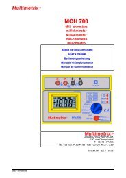
XM 2101<br />
Multimètre <strong>de</strong> table<br />
numérique<br />
20.000 points - 4 ½ digits<br />
20,000 count - 4 ½ digit<br />
Digital Benchtop<br />
Multimeter<br />
Notti ice <strong>de</strong> ffonctti ionnementt<br />
Userr’ ’s manuall<br />
Groupe CHAUVIN ARNOUX<br />
190, rue Championnet<br />
F - 75018 - PARIS<br />
Tél. +33 (0)1.44.85.44.85 - Fax +33 (0)1.46.27.73.89<br />
691025A00 - Ed. 3 - 04/03
Français<br />
Sommaire<br />
page<br />
Instructions générales .................................................................................................................3<br />
Introduction................................................................................................................................3<br />
Consignes <strong>de</strong> sécurité ...............................................................................................................3<br />
Symboles...................................................................................................................................4<br />
Ouverture <strong>de</strong> l'appareil...............................................................................................................4<br />
Dispositifs <strong>de</strong> protection.............................................................................................................5<br />
Dispositifs <strong>de</strong> sécurité................................................................................................................5<br />
Garantie.....................................................................................................................................5<br />
Maintenance ..............................................................................................................................5<br />
Déballage Ré-emballage ..........................................................................................................5<br />
Description <strong>de</strong> l’appareil..............................................................................................................6<br />
Introduction................................................................................................................................6<br />
Clavier <strong>de</strong> sélection « Fonction »...............................................................................................6<br />
Clavier <strong>de</strong> sélection « Calibre » .................................................................................................6<br />
Afficheur ....................................................................................................................................6<br />
Alimentation...............................................................................................................................6<br />
Bornes d'entrée .........................................................................................................................6<br />
Mise en service .............................................................................................................................7<br />
Limites <strong>de</strong>s bornes d’entrée.......................................................................................................7<br />
Entretien du multimètre..............................................................................................................7<br />
Nettoyage ..................................................................................................................................7<br />
Description <strong>de</strong> l’appareil..............................................................................................................8<br />
Illustration ..................................................................................................................................8<br />
Face avant.................................................................................................................................8<br />
Face arrière ...............................................................................................................................8<br />
Légen<strong>de</strong>.....................................................................................................................................8<br />
Description fonctionnelle.............................................................................................................9<br />
Mesure <strong>de</strong> tension .....................................................................................................................9<br />
Mesure <strong>de</strong> résistance ................................................................................................................9<br />
Mesure <strong>de</strong> dio<strong>de</strong>........................................................................................................................9<br />
Test <strong>de</strong> continuité ......................................................................................................................9<br />
Mesure <strong>de</strong> fréquence.................................................................................................................9<br />
Spécifications techniques ......................................................................................................... 10<br />
Tensions continues.................................................................................................................. 10<br />
Tensions alternatives............................................................................................................... 10<br />
Courants continus.................................................................................................................... 10<br />
Courants alternatifs.................................................................................................................. 10<br />
Mo<strong>de</strong> <strong>de</strong> Continuité.................................................................................................................. 11<br />
Fréquences.............................................................................................................................. 11<br />
Caractéristiques générales, Fourniture.................................................................................... 12<br />
Alimentation............................................................................................................................. 12<br />
Prises et douilles...................................................................................................................... 12<br />
Caractéristiques mécaniques................................................................................................... 12<br />
Environnement......................................................................................................................... 12<br />
Fusible ..................................................................................................................................... 12<br />
Accessoires ............................................................................................................................. 12<br />
livrés avec le multimètre .......................................................................................................... 12<br />
2 Multimètre <strong>de</strong> table numérique
Français<br />
Instructions générales<br />
Introduction Vous venez d'acquérir un multimètre <strong>de</strong> table numérique 4½ digits ;<br />
nous vous remercions <strong>de</strong> votre confiance.<br />
Ce multimètre est conforme à la norme <strong>de</strong> sécurité NF EN 61010-1<br />
(2001), relative aux instruments <strong>de</strong> mesures électroniques. Pour<br />
votre propre sécurité et celle <strong>de</strong> l'appareil, vous <strong>de</strong>vez respecter les<br />
consignes décrites dans cette notice.<br />
Sécurité<br />
Cet instrument, isolation classe 2, est utilisable pour <strong>de</strong>s mesures<br />
sur <strong>de</strong>s circuits <strong>de</strong> catégorie d'installation ΙΙ, dans un<br />
environnement <strong>de</strong> <strong>de</strong>gré <strong>de</strong> pollution 2, pour <strong>de</strong>s tensions<br />
n'excédant jamais 600 V (AC ou DC) par rapport à la terre.<br />
Définition<br />
<strong>de</strong>s catégories<br />
d'installation<br />
(cf. publication<br />
CEI 664-1)<br />
CAT I : Les circuits <strong>de</strong> CAT I sont <strong>de</strong>s circuits protégés par <strong>de</strong>s<br />
dispositifs limitant les surtensions transitoires à un faible<br />
niveau.<br />
Exemple : circuits électroniques protégés<br />
CAT II : Les circuits <strong>de</strong> CAT II sont <strong>de</strong>s circuits d'alimentation<br />
d'appareils domestiques ou analogues, pouvant comporter<br />
<strong>de</strong>s surtensions transitoires <strong>de</strong> valeur moyenne.<br />
Exemple : alimentation d'appareils ménagers et d'outillage<br />
portable<br />
CAT III : Les circuits <strong>de</strong> CAT III sont <strong>de</strong>s circuits d'alimentation<br />
d'appareils <strong>de</strong> puissance pouvant comporter <strong>de</strong>s<br />
surtensions transitoires importantes.<br />
Exemple : alimentation <strong>de</strong> machines ou appareils<br />
industriels<br />
CAT IV :Les circuits <strong>de</strong> CAT IV sont <strong>de</strong>s circuits pouvant comporter<br />
<strong>de</strong>s surtensions transitoires très importantes.<br />
Exemple : arrivées d'énergie<br />
Avant l'utilisation<br />
Pendant l'utilisation<br />
• Respecter les conditions d’environnement et <strong>de</strong> stockage.<br />
• S’assurer du bon état du cordon d’alimentation (trois fils : phase,<br />
neutre et terre) livré avec l'appareil conforme à la norme NF EN<br />
61010-1 (2001) raccordé, d’une part, à l’instrument et d’autre part,<br />
au réseau.<br />
• Ne dépassez jamais les valeurs limites <strong>de</strong> protection indiquées<br />
dans les spécifications propres à chaque type <strong>de</strong> mesure.<br />
• Lorsque le multimètre est relié aux circuits <strong>de</strong> mesure, ne<br />
touchez pas une borne non utilisée.<br />
• Lorsque l'ordre <strong>de</strong> gran<strong>de</strong>ur <strong>de</strong> la valeur à mesurer n'est pas<br />
connu, assurez-vous que le calibre <strong>de</strong> mesure <strong>de</strong> départ est le<br />
plus élevé possible.<br />
• Avant <strong>de</strong> changer <strong>de</strong> fonction, débranchez les cordons <strong>de</strong><br />
mesure du circuit mesuré.<br />
Multimètre <strong>de</strong> table numérique 3
Français<br />
Instructions générales (suite)<br />
Pendant l'utilisation<br />
(suite)<br />
Symboles<br />
utilisés<br />
• Lorsqu'on effectue <strong>de</strong>s mesures <strong>de</strong> courant, ne changez jamais<br />
<strong>de</strong> calibre, ne branchez ou débranchez pas les cordons sans<br />
que le courant n'ait été coupé. De telles manœuvres<br />
risqueraient <strong>de</strong> créer <strong>de</strong>s surtensions <strong>de</strong> rupture pouvant<br />
fondre les fusibles, ou endommager l'instrument.<br />
• En dépannage TV, ou lors <strong>de</strong> mesures sur <strong>de</strong>s circuits <strong>de</strong><br />
commutation <strong>de</strong> puissance <strong>de</strong>s impulsions <strong>de</strong> tension <strong>de</strong> forte<br />
amplitu<strong>de</strong> peuvent exister sur les points <strong>de</strong> mesure et<br />
endommager le multimètre. L'utilisation d'une son<strong>de</strong> <strong>de</strong> filtrage<br />
TV type HA0902 permet d'atténuer ces impulsions.<br />
• N’effectuez jamais <strong>de</strong> mesures <strong>de</strong> résistance sur un circuit<br />
sous tension.<br />
• Veillez à ne pas obstruer les aérations.<br />
Se reporter à la notice <strong>de</strong> <strong>fonctionnement</strong>.<br />
Une utilisation incorrecte peut endommager l'appareil et mettre en<br />
jeu la sécurité <strong>de</strong> l'utilisateur.<br />
Terre<br />
Ouverture <strong>de</strong><br />
l'appareil<br />
• Avant d'ouvrir l'instrument, déconnectez-le impérativement <strong>de</strong><br />
toute source <strong>de</strong> courant électrique et <strong>de</strong>s circuits <strong>de</strong> mesure et<br />
assurez-vous <strong>de</strong> ne pas être chargé d'électricité statique, ce qui<br />
pourrait entraîner la <strong>de</strong>struction d'éléments internes.<br />
• Le fusible doit être remplacé par un modèle i<strong>de</strong>ntique au fusible<br />
d'origine.<br />
• Tout réglage, entretien ou réparation du multimètre sous tension<br />
ne doit être effectué que par un personnel qualifié. Une<br />
"personne qualifiée" est une personne familière avec<br />
l'installation, la construction, l'utilisation et les dangers présentés.<br />
Elle est autorisée à mettre en service et hors service l'installation<br />
et les équipements, conformément aux règles <strong>de</strong> sécurité.<br />
• Lorsque l'appareil est ouvert, certains con<strong>de</strong>nsateurs internes<br />
peuvent conserver un potentiel dangereux même après avoir mis<br />
l'appareil hors tension.<br />
• En cas <strong>de</strong> défauts ou contraintes anormales, mettez l'appareil<br />
hors service et empêcher son utilisation jusqu'à ce qu'il soit<br />
procédé à sa vérification.<br />
4 Multimètre <strong>de</strong> table numérique
Français<br />
Instructions générales (suite)<br />
Dispositifs <strong>de</strong><br />
protection<br />
Dispositifs <strong>de</strong><br />
sécurité<br />
Garantie<br />
Maintenance<br />
Déballage<br />
Ré-emballage<br />
• 1 fusible assure une protection lors <strong>de</strong> mesures <strong>de</strong> type<br />
intensité.<br />
• Protection limitée à 600 V entre les bornes mA et 10 A.<br />
Lors d'un dépassement <strong>de</strong> gamme persistant, un signal sonore<br />
intermittent indique le risque <strong>de</strong> choc électrique.<br />
Ce matériel est garanti contre tout défaut <strong>de</strong> matière ou vice <strong>de</strong><br />
fabrication, conformément aux conditions générales <strong>de</strong> vente.<br />
Durant la pério<strong>de</strong> <strong>de</strong> garantie (1 an), l'appareil ne peut être réparé<br />
que par le constructeur, celui-ci se réservant la décision <strong>de</strong><br />
procé<strong>de</strong>r soit à la réparation, soit à l'échange <strong>de</strong> tout ou partie <strong>de</strong><br />
l'appareil. En cas <strong>de</strong> retour du matériel au constructeur, le transport<br />
aller est à la charge du client.<br />
La garantie ne s’applique pas suite à :<br />
1. une utilisation impropre du matériel ou par association <strong>de</strong><br />
celui-ci avec un équipement incompatible ;<br />
2. une modification du matériel sans autorisation explicite <strong>de</strong>s<br />
services techniques du constructeur ;<br />
3. l’intervention effectuée par une personne non agréée par le<br />
constructeur ;<br />
4. l'adaptation à une application particulière, non prévue par la<br />
définition du matériel ou par la notice <strong>de</strong> <strong>fonctionnement</strong> ;<br />
5. un choc, une chute ou une inondation.<br />
Le contenu <strong>de</strong> cette notice ne peut être reproduit, sous quelque<br />
forme que ce soit, sans notre accord.<br />
Renseignements, coordonnées: MANUMESURE<br />
REUX<br />
14130 - PONT L’EVEQUE<br />
Tél. 02.31.64.51.55 Fax 02.31.64.51.09<br />
L’ensemble du matériel a été vérifié mécaniquement et électriquement<br />
avant l’expédition. Toutes les précautions ont été prises pour<br />
que l’instrument parvienne sans dommage à l’utilisateur.<br />
Toutefois, il est pru<strong>de</strong>nt <strong>de</strong> procé<strong>de</strong>r à une vérification rapi<strong>de</strong> pour<br />
détecter toute détérioration éventuelle pouvant avoir été<br />
occasionnée lors du transport.<br />
S’il en est ainsi, faites immédiatement les réserves d’usage auprès<br />
du transporteur.<br />
Dans le cas d’une réexpédition, utiliser <strong>de</strong> préférence l’emballage<br />
d’origine et indiquer, le plus clairement possible, par une note jointe<br />
au matériel les motifs du renvoi.<br />
Multimètre <strong>de</strong> table numérique 5
Français<br />
Description <strong>de</strong> l’appareil<br />
Introduction<br />
Clavier <strong>de</strong> sélection<br />
« Fonction »<br />
Clavier <strong>de</strong> sélection<br />
« Calibre »<br />
Ce multimètre <strong>de</strong> table est un instrument <strong>de</strong> mesure professionnel,<br />
portable permettant <strong>de</strong> mesurer, grâce à un clavier <strong>de</strong> 7 touches,<br />
les gran<strong>de</strong>urs suivantes avec une précision <strong>de</strong> base <strong>de</strong> 0,05 % :<br />
∗ tensions alternatives jusqu’à 750 V<br />
∗ tensions continues jusqu’à 1000 V<br />
∗ courants alternatifs jusqu’à 10 A<br />
∗ courants continus jusqu’à 10 A<br />
∗ résistances jusqu’à 20 MΩ<br />
∗ continuité sonore<br />
∗ tensions <strong>de</strong> seuil dio<strong>de</strong>s<br />
∗ mesure en fréquences jusqu’à 200 kHz<br />
Un clavier <strong>de</strong> 7 touches permet <strong>de</strong> sélectionner le mo<strong>de</strong> <strong>de</strong><br />
changement <strong>de</strong> gammes:<br />
∗ 2 2 V, 2 mA, 2 kΩ<br />
∗ 20 20 V, 20 mA, 20 kΩ, 20 kHz<br />
∗ 200 200 V, 200 mA, 200 kΩ, 200 kHz<br />
∗ 2000 DC 1000 V, AC 750 V, 2000 mA, 2000 kΩ<br />
∗ 20 MΩ<br />
∗ 10 A<br />
∗ HOLD<br />
Afficheur L'afficheur permet :<br />
∗ une lecture confortable <strong>de</strong>s chiffres<br />
∗ <strong>de</strong>s mesures sur 20.000 points<br />
Alimentation L'alimentation se fait à partir du réseau 230 V.<br />
Bornes d'entrée<br />
Les mesures sont effectuées au moyen <strong>de</strong>s 2 cordons <strong>de</strong> mesure<br />
livrés avec l'appareil reliés aux 4 bornes d'entrée :<br />
∗ V/Ω/Hz/Continuité/Dio<strong>de</strong> : tension, résistance, continuité, dio<strong>de</strong><br />
∗ COM :<br />
référence multimètre<br />
∗ mA :<br />
calibres mA<br />
∗ A :<br />
calibres A<br />
6 Multimètre <strong>de</strong> table numérique
Français<br />
Mise en service<br />
Limites <strong>de</strong>s bornes<br />
d’entrée<br />
Touche<br />
«Fonction»<br />
Bornes<br />
d’entrée<br />
Lecture min.<br />
Lecture max.<br />
Entrée<br />
max.<br />
VDC<br />
VAC<br />
V/Ω/Hz<br />
COM<br />
V/Ω/Hz<br />
COM<br />
0.0001 V 1000.0 V 1000 VDC<br />
0.0001 V 750.0 V 750 VAC<br />
Ω<br />
V/Ω/Hz<br />
COM<br />
0.0001 kΩ 19.999 MΩ<br />
600 V<br />
(1 min)<br />
Dio<strong>de</strong> /<br />
Cont.<br />
V/Ω/Hz<br />
COM<br />
0.1 1999.9<br />
600 V<br />
(1 min)<br />
mADC mA COM 0.0001 mA 1999.9 mA 2 A<br />
mAAC mA COM 0.0001 mA 1999.9 mA 2 A<br />
ADC A COM 0.001 A 10.000 A 10.00 A<br />
AAC A COM 0.001 A 10.000 A 10.00 A<br />
Fréquence<br />
V/Ω/Hz<br />
COM<br />
0.001 kHz 199.99 kHz<br />
600 V<br />
(1 min)<br />
Entretien du<br />
multimètre<br />
Remplacement <strong>de</strong>s<br />
fusibles<br />
• Déconnectez l’instrument <strong>de</strong> toute source d’énergie.<br />
• Déposer le support fusible situé à l’arrière <strong>de</strong> l’appareil<br />
(repère 16).<br />
• Localisez le fusible défectueux et retirez-le délicatement.<br />
• Mettez en place le nouveau fusible.<br />
• Revissez le support fusible.<br />
Attention !<br />
Les fusibles doivent être remplacés exclusivement avec <strong>de</strong>s<br />
fusibles <strong>de</strong> modèle i<strong>de</strong>ntique : 200 mA, 250 V, rapi<strong>de</strong>.<br />
Nettoyage<br />
• Mettez l’instrument hors tension.<br />
• Nettoyez-le avec un chiffon humi<strong>de</strong> et du savon.<br />
• N’utilisez jamais <strong>de</strong> produits abrasifs, ni <strong>de</strong> solvants.<br />
• Laissez sécher avant toute nouvelle utilisation.<br />
Multimètre <strong>de</strong> table numérique 7
Français<br />
Description <strong>de</strong> l’appareil<br />
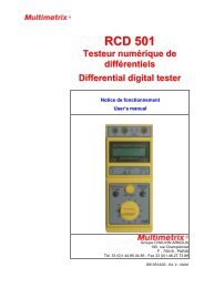
Illustration<br />
b c d e<br />
Face avant<br />
∆ΙΓ ΙΤΑΛ ΜΥΛΤΙΜΕΤΕΡ<br />
ς<br />
Ηζ<br />
ΑΧ<br />
Ηζ .<br />
ς<br />
Α<br />
∆Χ<br />
µΑ<br />
Α<br />
κ<br />
1000ς<br />
750ς<br />
ΜΑΞ<br />
ΦΥΣ Ε ∆<br />
10Α ΜΑΞ<br />
Η<br />
Μ<br />
κΗζ<br />
ΧΟΜ<br />
µΑ<br />
ΠΟΩ ΕΡ<br />
500ς<br />
ΦΥΣ Ε ∆<br />
2000µ Α ΜΑΞ<br />
ΟΝ<br />
ΟΦΦ<br />
ς<br />
ς<br />
Α<br />
ΦΥΝΧΤΙΟ Ν<br />
Α<br />
Ηζ<br />
2<br />
20<br />
Ρ ΑΝΓ Ε<br />
200 2000 20Μ<br />
10Α<br />
κΗζ<br />
ς/µΑ/κ<br />
750ς<br />
1000ς<br />
ΗΟΛ∆<br />
1 2 3<br />
4<br />
5 6 7 8 9 10 11 12 13 14 a<br />
Face arrière<br />
230ς ∼, 50Ηζ/60Ηζ<br />
ΩΑΡΝΙΝΓ<br />
ΤΟ ΠΡ Ες ΕΝΤ ΕΛΕΧΤΡ ΙΧ ΣΗΟΧΚ ΗΑΖΑΡ ∆ ΑΝ∆ ΦΙΡ Ε,<br />
Ρ ΕΠΛΑΧΕ ΟΝΛΨ Ω ΙΤΗ ΦΥΣΕ ΟΦ ΣΑΜΕ ΡΑΤΙΝΓ ΑΝ∆ ΤΨΠΕ.<br />
∆ΙΣΧΟΝΝΕΧΤ ΠΟΩ ΕΡ ΣΥΠΠΛΨ ΒΕΦΟΡ Ε Ρ ΕΠΛΑΧΙΝΓ ΦΥΣΕ.<br />
∆Ο ΝΟΤ ΡΕΜΟςΕ ΧΟςΕΡ. ΡΕΦΕΡ ΣΕΡςΙΧΙΝΓ ΤΟ<br />
ΘΥΑΛΙΦΙΕ∆ ΠΕΡ ΣΟΝΝΕΛ.<br />
ΦΥΣ Ε<br />
15<br />
16<br />
Légen<strong>de</strong><br />
1 Touche Marche/Arrêt 12 Mesure DC jusqu’à 100 V<br />
2 Mesure <strong>de</strong> tension continue 13 Mesure jusqu’à 20 MΩ<br />
3 Mesure <strong>de</strong> tension alternative 14 Mesure <strong>de</strong> courant jusqu’à 10 A<br />
4 Mesure <strong>de</strong> courant continu 15 Alimentation secteur<br />
5 Mesure <strong>de</strong> courant alternatif 16 Support fusible<br />
6 Mesure <strong>de</strong> résistance a Data Hold<br />
7 Mesure <strong>de</strong> continuité et mesure dio<strong>de</strong> b Borne d’entrée COM<br />
8 Mesure <strong>de</strong> fréquence c Borne d’entrée :<br />
9 Mesure jusqu’à 2 V / mA / kΩ V / Ω / Hz / dio<strong>de</strong> / continuité<br />
10 Mesure jusqu’à 20 V / mA / kΩ d Borne d’entrée mA<br />
11 Mesure jusqu’à 200 V / mA / kΩ e Borne d’entrée A<br />
8 Multimètre <strong>de</strong> table numérique
Français<br />
Description fonctionnelle<br />
Mesure <strong>de</strong> tension<br />
Mesure <strong>de</strong> courant<br />
Mesure <strong>de</strong><br />
résistance<br />
1. Connectez les cordons rouge et noir respectivement dans la borne<br />
d’entrée VΩ et COM.<br />
2. Vérifiez AC et DC. Sélectionnez la fonction VDC ou VAC et<br />
enfoncez la touche « Calibre » <strong>de</strong> la position volt désirée.<br />
3. Mettez les pointes <strong>de</strong> touche sur la tension à mesurer.<br />
4. Lisez la valeur <strong>de</strong> la tension sur l’afficheur.<br />
1. Connectez le cordon rouge dans la borne d’entrée « mA » pour un<br />
courant inférieur à 2000 mADC ou dans la borne d’entrée « A »<br />
pour un courant entre 2000 mA et 10 A.<br />
2. Connectez le cordon noir dans la borne d’entrée COM.<br />
3. Vérifiez DC ou AC. Sélectionnez la fonction (ADC ou A AC) et<br />
enfoncez la touche « Calibre » <strong>de</strong> la position courant désirée.<br />
4. Mettez les pointes <strong>de</strong> touche sur le courant à mesurer.<br />
5. Lisez la valeur du courant sur l’afficheur.<br />
1. Connectez les cordons rouge et noir respectivement dans les<br />
bornes d’entrée VΩ et COM.<br />
2. Sélectionnez la fonction Ω et enfoncez la touche « Calibre » <strong>de</strong> la<br />
résistance désirée.<br />
3. Mettez les pointes <strong>de</strong> touche sur la résistance à mesurer.<br />
4. Lisez la valeur <strong>de</strong> la résistance sur l’afficheur.<br />
Mesure <strong>de</strong> dio<strong>de</strong> 1. Sélectionnez le calibre 2 V.<br />
2. Connectez la son<strong>de</strong> rouge à l’extrémité positive <strong>de</strong> la dio<strong>de</strong> et<br />
la son<strong>de</strong> noire à l’extrémité négative <strong>de</strong> la dio<strong>de</strong>.<br />
3. Si la dio<strong>de</strong> est bonne, la chute <strong>de</strong> tension s’affiche.<br />
(Exemple : 300.0 ~ 800.0)<br />
4. Inversez les son<strong>de</strong>s et mesurez à nouveau la tension à travers<br />
la dio<strong>de</strong>.<br />
• Si la dio<strong>de</strong> est bonne, l’afficheur montre « 000.0 » et clignote.<br />
• Si la dio<strong>de</strong> est en court-circuit, l’afficheur montre « 000.0 » avec un<br />
signal sonore dans les <strong>de</strong>ux directions.<br />
• Si l’afficheur montre « 000.0 » et clignote dans les <strong>de</strong>ux directions,<br />
la dio<strong>de</strong> est ouverte.<br />
Test <strong>de</strong> continuité<br />
Mesure <strong>de</strong><br />
fréquence<br />
Remarque<br />
1. Sélectionnez la touche fonction « Continuité » et enfoncez la<br />
touche gamme « Dio<strong>de</strong> ».<br />
2. Appliquez les son<strong>de</strong>s sur le circuit à mesurer. Le beeper retentit,<br />
confirmant que le circuit est fermé et connecté.<br />
1. Connectez les cordons rouge et noir respectivement dans les<br />
bornes d’entrée VΩ et COM.<br />
2. Sélectionnez la fonction « FRQ » et enfoncez la touche « Calibre »<br />
<strong>de</strong> la fréquence désirée.<br />
3. Appliquez les pointes <strong>de</strong> touche sur le circuit à mesurer.<br />
4. Lisez la valeur <strong>de</strong> la fréquence sur l’afficheur.<br />
Erreur additionnelle < décalage <strong>de</strong> 5 points (mesurer l’erreur en<br />
court-circuitant l’entrée)<br />
Multimètre <strong>de</strong> table numérique 9
Français<br />
Spécifications techniques<br />
Tensions continues<br />
Les spécifications ne sont garanties qu’après une mise en<br />
température <strong>de</strong> 30 minutes.<br />
Gamme Résolution Précision Impédance<br />
2 V 100 µV ± (0,05 % + 5 d)<br />
20 V<br />
1 mV<br />
200 V<br />
10 mV<br />
1000 V 100 m V<br />
± (0,1 % + 10 d)<br />
10 MΩ<br />
Tensions<br />
alternatives<br />
Gamme<br />
Résolution<br />
Précision<br />
50 - 60 Hz 60 - 400 Hz<br />
Impédance<br />
2 V<br />
100 µV<br />
± (1.5 % + 10 d)<br />
20 V<br />
200 V<br />
1 mV<br />
10 mV<br />
± (0,75 % + 10 d)<br />
± (2.5 % + 10 d)<br />
10 MΩ<br />
750 V<br />
100 mV<br />
Courants continus<br />
Gamme Résolution Précision Protection<br />
2 mA<br />
100 nA<br />
20 mA<br />
1 µA ± (0,5 % + 5 d)<br />
200 mA<br />
10 µA<br />
2 A / 250 V<br />
2 A 100 µA ± (0,75 % + 5 d)<br />
10 A 1 mA ± (1,0 % + 10 d) 10 A / 250 V<br />
Courants alternatifs<br />
Gamme<br />
Résolution<br />
Précision<br />
50 - 60Hz 60 - 400 Hz<br />
Protection<br />
2 mA<br />
20 mA<br />
200 mA<br />
2 A<br />
10 A<br />
100 nA<br />
1 µA<br />
10 µA<br />
100 µA<br />
1 mA<br />
± (0,75 %<br />
+ 10 d)<br />
± (1,0 %<br />
+ 10 d)<br />
± (2,0 %<br />
+ 10 d)<br />
2 A / 250 V<br />
10 A / 250 V<br />
10 Multimètre <strong>de</strong> table numérique
Français<br />
Spécifications techniques (suite)<br />
Résistances<br />
Gamme Résolution Précision Protection<br />
2 kΩ<br />
0,1 Ω<br />
20 kΩ<br />
200 kΩ<br />
1 Ω<br />
10 Ω<br />
± (0,2 % + 5 d)<br />
600 VDC ou Peak<br />
2 MΩ<br />
100 Ω<br />
20 MΩ 1 kΩ ± (1 % + 10 d)<br />
Mo<strong>de</strong> <strong>de</strong> Continuité<br />
Tension <strong>de</strong> mesure Seuil Protection<br />
3 V < 200 Ω 600 VDC ou Peak<br />
Test dio<strong>de</strong><br />
Tension <strong>de</strong> mesure Courant <strong>de</strong> test max. Protection<br />
2 V env. 1,0 mA 600 VDC ou Peak<br />
Fréquences<br />
Gamme Résolution Précision Protection<br />
20 kHz 1 Hz ± (1,0 % + 5 d)<br />
600 VDC ou Peak<br />
200 kHz 10 Hz ± (2,0 % + 5 d)<br />
Erreur additionnelle < décalage <strong>de</strong> 5 points<br />
Multimètre <strong>de</strong> table numérique 11
Français<br />
Caractéristiques générales, Fourniture<br />
Alimentation<br />
Prises et douilles<br />
Caractéristiques<br />
mécaniques<br />
230 VAC ± 10 %, 50 - 60 Hz , 10 W maximum<br />
3 fils<br />
Dimensions<br />
240 x 90 x 280 mm<br />
Poids<br />
1,9 kg<br />
Etanchéité IP 00, selon NF EN 60529 (1992)<br />
Environnement Température <strong>de</strong> référence 23°C ± 5°C<br />
Température d’utilisation 0°C à + 40°C<br />
Coefficient <strong>de</strong> température 0,1 x précision par °C<br />
Température <strong>de</strong> stockage - 20°C à + 70°C<br />
Humidité<br />
< 85 % HR à 40°C max.<br />
Fusible<br />
200 mA, 250 V, rapi<strong>de</strong><br />
Accessoires<br />
livrés avec le<br />
multimètre<br />
1 jeu <strong>de</strong> cordons - pointes <strong>de</strong> touche <strong>de</strong> sécurité<br />
1 cordon secteur<br />
1 fusible <strong>de</strong> rechange<br />
1 notice <strong>de</strong> <strong>fonctionnement</strong><br />
12 Multimètre <strong>de</strong> table numérique
English<br />
Contents<br />
page<br />
General Instructions................................................................................................................... 14<br />
Introduction.............................................................................................................................. 14<br />
Safety measures...................................................................................................................... 14<br />
Symbols................................................................................................................................... 15<br />
Opening the instrument ........................................................................................................... 15<br />
Input protection <strong>de</strong>vices........................................................................................................... 16<br />
Safety <strong>de</strong>vices ......................................................................................................................... 16<br />
Guarantee................................................................................................................................ 16<br />
Maintenance, metrological verification..................................................................................... 16<br />
Unpacking Repacking............................................................................................................. 16<br />
Instrument Description .............................................................................................................. 17<br />
Introduction.............................................................................................................................. 17<br />
« Function » selection keypad ................................................................................................. 17<br />
« Range » selection keypad .................................................................................................... 17<br />
Display..................................................................................................................................... 17<br />
Power supply ........................................................................................................................... 17<br />
Input terminals ......................................................................................................................... 17<br />
Operation..................................................................................................................................... 18<br />
Input terminal limits.................................................................................................................. 18<br />
Multimeter maintenance .......................................................................................................... 18<br />
Case cleaning.......................................................................................................................... 18<br />
Instrument Description .............................................................................................................. 19<br />
Illustration ................................................................................................................................ 19<br />
Front face ................................................................................................................................ 19<br />
Rear panel ............................................................................................................................... 19<br />
Caption .................................................................................................................................... 19<br />
Functional Description............................................................................................................... 20<br />
Voltage measurement.............................................................................................................. 20<br />
Resistance measurement ........................................................................................................ 20<br />
Dio<strong>de</strong> test ................................................................................................................................ 20<br />
Continuity test.......................................................................................................................... 20<br />
Frequency measurement......................................................................................................... 20<br />
Technical specifications ............................................................................................................ 21<br />
DC voltage............................................................................................................................... 21<br />
AC voltage ............................................................................................................................... 21<br />
DC current ............................................................................................................................... 21<br />
AC current ............................................................................................................................... 21<br />
Continuity mo<strong>de</strong>....................................................................................................................... 22<br />
Frequency................................................................................................................................ 22<br />
General specifications, Supply .................................................................................................23<br />
Power ...................................................................................................................................... 23<br />
Plug and socket ....................................................................................................................... 23<br />
Mechnical features................................................................................................................... 23<br />
Environment............................................................................................................................. 23<br />
Fuse......................................................................................................................................... 23<br />
Accessories <strong>de</strong>livered with the multimeter............................................................................... 23<br />
Digital Benchtop Multimeter 13
English<br />
General Instructions<br />
Introduction<br />
You have just purchased a 20,000-count 4½-digit benchtop<br />
multimeter. Thank you for your confi<strong>de</strong>nce in the quality of our<br />
products.<br />
This instrument conforms to safety standard NF EN 61010-1 (2001),<br />
relating to electronic measuring instruments. For best quality<br />
service, please read these instructions carefully and respect<br />
operating precautions.<br />
Safety<br />
This instrument, single insulation, was <strong>de</strong>signed for indoor use, in a<br />
level 2 pollution environment, at an altitu<strong>de</strong> below 2,000 m, It can be<br />
used for CAT II installation circuit measurements, for voltage never<br />
exceeding 600 V (AC or DC) in relation to earth.<br />
Definition of<br />
installation<br />
categories<br />
(cf. IEC 664-1<br />
publication)<br />
Before use<br />
During use<br />
CAT I: CAT I circuits are protected by <strong>de</strong>vices limiting transient<br />
overvoltage to a low level.<br />
Example: protected electronic circuits<br />
CAT II: CAT II circuits are power supply circuits for household or<br />
analog units that can support medium-level transient<br />
overvoltage.<br />
Example: household appliance and portable tool power<br />
supply<br />
CAT III: CAT III circuits are power supply circuits that can support<br />
major transient overvoltage.<br />
Example: industrial unit or machine power supply<br />
CAT IV: CAT IV circuits can support very high transient overvoltage.<br />
Example: power input<br />
• Respect environment and storage requirements.<br />
• Make sure that power cable supplied with the unit is in good<br />
operating condition (three-wire network: phase, neutral and<br />
earth), conforms to safety standard NF EN 61010-1 (2001) and is<br />
connected to instrument as well as network.<br />
• Never exceed the protection limit values indicated in the<br />
specifications for each type of measurement.<br />
• When the multimeter is linked to measurement circuits, do not<br />
touch unused terminals.<br />
• When the scale of the value to be measured is unknown, check<br />
that the scale initially set on the multimeter is the highest possible<br />
or, wherever possible, choose the autoranging mo<strong>de</strong>.<br />
• Before changing functions, disconnect the test leads from the<br />
circuit un<strong>de</strong>r test.<br />
14 Digital Benchtop Multimeter
English<br />
General Instructions (cont’d)<br />
During use (cont’d)<br />
• When performing current measurements, never change of<br />
range, do not connect or disconnect leads without first isolating<br />
the current. If you do, there is a risk of generating surge<br />
currents, which can blow the fuses or damage the instrument.<br />
• In TV repair work, or when carrying out measurements on power<br />
switching circuits, remember that high amplitu<strong>de</strong> voltage pulses<br />
at the test points can damage the multimeter. Use of a type TV<br />
filter will attenuate any such pulses.<br />
• Never perform resistance measurements on live circuits.<br />
• Make sure that you do not block ventilation.<br />
Symbols<br />
on instrument<br />
Refer to user’s manual.<br />
Incorrect use can damage unit and be a safety hazard for user.<br />
Earth<br />
Opening the<br />
instrument<br />
• Before opening the instrument, always disconnect from all<br />
sources of electric current and make sure not to be loa<strong>de</strong>d with<br />
static electricity, which may <strong>de</strong>stroy internal components.<br />
• Fuses must be replaced with fuses of the same rating and type.<br />
• Any adjustment, maintenance or repair work carried out on the<br />
multimeter while it is live should be carried out only by<br />
appropriately qualified personnel. A "qualified person" is one<br />
who is familiar with the installation, construction and operation of<br />
the equipment and the hazards involved. He is trained and<br />
authorized to energize, <strong>de</strong>-energize circuits and equipment in<br />
accordance with established practices.<br />
• When the instrument is open, remember that some internal<br />
capacitors can retain a dangerous potential even after the<br />
instrument is powered down.<br />
• If any faults or abnormalities are observed, take the instrument<br />
out of service and ensure that it cannot be used until it has been<br />
checked out.<br />
Digital Benchtop Multimeter 15
English<br />
General instructions (cont’d)<br />
Input protection<br />
<strong>de</strong>vices<br />
Safety <strong>de</strong>vices<br />
Guarantee<br />
• A fuse ensures protection during intensity-type measurements.<br />
• Protection limited to 600 V between mA and 10 A terminals.<br />
If range is persistently excee<strong>de</strong>d, an intermittent audible signal<br />
indicates an electric shock risk.<br />
This equipment is guaranteed against any <strong>de</strong>fect in materials or<br />
faulty manufacture, in compliance with general terms and conditions<br />
of sale.<br />
During the warranty period (1 year), the unit can only be repaired by<br />
the manufacturer and only the latter can <strong>de</strong>ci<strong>de</strong> if all or part of the<br />
equipment should be repaired or exchanged. If equipment is<br />
returned to the manufacturer, outward transport will be paid by the<br />
customer.<br />
The warranty does not apply after the following:<br />
• Improper use of unit or using the latter with incompatible<br />
equipment<br />
• Modifying equipment without prior explicit authorisation from<br />
manufacturer technical <strong>de</strong>partments<br />
• Intervention by a person not approved by the manufacturer<br />
• Adapting for a particular application not planned by the equipment<br />
<strong>de</strong>finition or operating instructions<br />
• Shock, fall or flooding.<br />
The contents of these instructions cannot be reproduced, in any<br />
way, without prior manufacturer agreement.<br />
Maintenance,<br />
metrological<br />
verification<br />
Unpacking<br />
Repacking<br />
Return your instrument to your distributor for any work to be done<br />
within or outsi<strong>de</strong> the guarantee.<br />
All the equipment has been checked mechanically and electrically<br />
before shipping.<br />
On reception, carry out a quick check to <strong>de</strong>tect any damage caused by<br />
transport. If necessary, contact our commercial <strong>de</strong>partment<br />
immediately and make all legal reservations with the carrier.<br />
In the event of reshipping, it is preferable to use the original package.<br />
Indicate as clearly as possible, by a note attached to the equipment,<br />
the reasons for the return.<br />
16 Digital Benchtop Multimeter
English<br />
Instrument Description<br />
Introduction<br />
« Function »<br />
selection keypad<br />
« Range »<br />
selection keypad<br />
Display<br />
The benchtop multimeter is a professional measuring instrument,<br />
capable of measuring the following quantities (accessed by the 7-<br />
key keypad) with a basic accuracy of 0.05 % :<br />
∗ AC voltages up to 750 V<br />
∗ DC voltages up to 1000 V<br />
∗ AC currents up to 10 A<br />
∗ DC currents up to 10 A<br />
∗ Resistances up to 20 MΩ<br />
∗ Audible continuity test<br />
∗ Dio<strong>de</strong> threshold<br />
∗ Frequency measurements up to 200 kHz<br />
A seven-key key pad lets you select the autoranging mo<strong>de</strong> :<br />
∗ 2 2 V, 2 mA, 2 kΩ<br />
∗ 20 20 V, 20 mA, 20 kΩ, 20 kHz<br />
∗ 200 200 V, 200 mA, 200 kΩ, 200 kHz<br />
∗ 2000 DC 1000 V, AC 750 V, 2000 mA, 2000 kΩ<br />
∗ 20 MΩ<br />
∗ 10 A<br />
∗ HOLD<br />
The multimeter display provi<strong>de</strong>s:<br />
• clearly legible figures<br />
• perform 20,000-count measurements (high resolution)<br />
Power supply The multimeter is powered directly from the mains 230 V.<br />
Input terminals<br />
Measurements are performed using two measuring leads supplied<br />
with the instrument connected to input terminals 1, 2, 3 and 4 :<br />
∗ V/Ω/Hz/Continuity/Dio<strong>de</strong> : voltage, resistance, continuity, dio<strong>de</strong><br />
∗ COM :<br />
multimeter reference<br />
∗ mA :<br />
mA ranges<br />
∗ A :<br />
A ranges<br />
Digital Benchtop Multimeter 17
English<br />
Operation<br />
Input terminal limits<br />
Switch<br />
«Function»<br />
Input<br />
terminals<br />
Min. display<br />
reading<br />
Max. display<br />
reading<br />
Max. input<br />
VDC<br />
VAC<br />
V/Ω/Hz<br />
COM<br />
V/Ω/Hz<br />
COM<br />
0.0001 V 1000.0 V 1000 VDC<br />
0.0001 V 750.0 V 750 VAC<br />
Ω<br />
V/Ω/Hz<br />
COM<br />
0.0001 kΩ 19.999 MΩ<br />
600 V<br />
(1 min)<br />
Dio<strong>de</strong> /<br />
Cont.<br />
V/Ω/Hz<br />
COM<br />
0.1 1999.9<br />
600 V<br />
(1 min)<br />
mADC mA COM 0.0001 mA 1999.9 mA 2 A<br />
mAAC mA COM 0.0001 mA 1999.9 mA 2 A<br />
ADC A COM 0.001 A 10.000 A 10.00 A<br />
AAC A COM 0.001 A 10.000 A 10.00 A<br />
Frequency<br />
V/Ω/Hz<br />
COM<br />
0.001 kHz 199.99 kHz<br />
600 V<br />
(1 min)<br />
Multimeter<br />
maintenance<br />
Fuse replacement<br />
• Switch off the instrument.<br />
• Unscrew the fuse hol<strong>de</strong>r located at the back of the instrument (16).<br />
• Take the <strong>de</strong>fect fuse away.<br />
• Replace with new fuse of same type.<br />
• Re-position the fuse hol<strong>de</strong>r.<br />
Warning !<br />
The fuses must be replaced only with fuses of same mo<strong>de</strong>l :<br />
200 mA, 250 V, fast.<br />
Case cleaning<br />
• Turn off the instrument.<br />
• Clean it with a damp cloth and soap.<br />
• Do not use abrasive products or solvents.<br />
• Leave to dry before using it again.<br />
18 Digital Benchtop Multimeter
English<br />
Instrument Description<br />
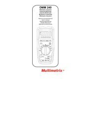
Illustration<br />
b c d e<br />
Front face<br />
∆ΙΓ ΙΤΑΛ ΜΥΛΤΙΜΕΤΕΡ<br />
ς<br />
Ηζ<br />
ΑΧ<br />
Ηζ .<br />
ς<br />
Α<br />
∆Χ<br />
µΑ<br />
Α<br />
κ<br />
1000ς<br />
750ς<br />
ΜΑΞ<br />
ΦΥΣ Ε ∆<br />
10Α ΜΑΞ<br />
Η<br />
Μ<br />
κΗζ<br />
ΧΟΜ<br />
µΑ<br />
ΠΟΩ ΕΡ<br />
500ς<br />
ΦΥΣ Ε ∆<br />
2000µ Α ΜΑΞ<br />
ΟΝ<br />
ΟΦΦ<br />
ς<br />
ς<br />
Α<br />
ΦΥΝΧΤΙΟ Ν<br />
Α<br />
Ηζ<br />
2<br />
20<br />
Ρ ΑΝΓ Ε<br />
200 2000 20Μ<br />
10Α<br />
κΗζ<br />
ς/µΑ/κ<br />
750ς<br />
1000ς<br />
ΗΟΛ∆<br />
1 2 3<br />
4<br />
5 6 7 8 9 10 11 12 13 14 a<br />
Rear panel<br />
230ς ∼, 50Ηζ/60Ηζ<br />
ΩΑΡΝΙΝΓ<br />
ΤΟ ΠΡ Ες ΕΝΤ ΕΛΕΧΤΡ ΙΧ ΣΗΟΧΚ ΗΑΖΑΡ ∆ ΑΝ∆ ΦΙΡ Ε,<br />
Ρ ΕΠΛΑΧΕ ΟΝΛΨ Ω ΙΤΗ ΦΥΣΕ ΟΦ ΣΑΜΕ ΡΑΤΙΝΓ ΑΝ∆ ΤΨΠΕ.<br />
∆ΙΣΧΟΝΝΕΧΤ ΠΟΩ ΕΡ ΣΥΠΠΛΨ ΒΕΦΟΡ Ε Ρ ΕΠΛΑΧΙΝΓ ΦΥΣΕ.<br />
∆Ο ΝΟΤ ΡΕΜΟςΕ ΧΟςΕΡ. ΡΕΦΕΡ ΣΕΡςΙΧΙΝΓ ΤΟ<br />
ΘΥΑΛΙΦΙΕ∆ ΠΕΡ ΣΟΝΝΕΛ.<br />
ΦΥΣ Ε<br />
15<br />
16<br />
Caption<br />
1 ON/OFF Switch 12 DC measurement up to 100 V<br />
2 DC voltage measurement 13 Measurement up to 20 MΩ<br />
3 AC voltage measurement 14 Current measurement up to 10 A<br />
4 DC current measurement 15 Mains socket<br />
5 AC current measurement 16 Fuse hol<strong>de</strong>r<br />
6 Resistance measurement a Data Hold<br />
7 Dio<strong>de</strong> and continuity test b COM input terminal<br />
8 Frequency measurement c Input terminals :<br />
9 Measurement up to 2 V / mA / kΩ V / Ω / Hz / Dio<strong>de</strong> / Continuity<br />
10 Measurment up to 20 V / mA / kΩ d mA input terminal<br />
11 Measurement up to 200 V / mA / kΩ e A input terminal<br />
Digital Benchtop Multimeter 19
English<br />
Functional Description<br />
Voltage<br />
measurement<br />
Current<br />
measurement<br />
Resistance<br />
measurement<br />
1. Plug the red and the black test leads into « VΩ » and « COM » input<br />
terminals respectively.<br />
2. Verify AC or DC. Select the function VDC or VAC and set the range<br />
switch to the <strong>de</strong>sired volt range.<br />
3. Connect the probe tips in parallel with the voltage source to be<br />
measured.<br />
4. Read voltage value on the display.<br />
1. Connect the red test lead into the « mA » input terminal for less than<br />
2000 mADC or into « A » input terminal between 2000 mA and 10 A.<br />
2. Connect the black test lead into the « COM » input terminal.<br />
3. Verify AC or DC. Select the function (ADC or AAC) and set the<br />
range switch to the <strong>de</strong>sired current range.<br />
4. Connect the probe tips in parallel with the current source to be<br />
measured.<br />
5. Read current value on the display.<br />
1. Plug the red and the black test leads into « VΩ » and « COM » input<br />
terminals respectively.<br />
2. Select the Ω function and set the range switch to the <strong>de</strong>sired<br />
resistance range.<br />
3. Connect the probe tips in parallel with the resistance to be measured.<br />
4. Read resistance value on the display.<br />
Dio<strong>de</strong> test 1. Select the range 2 V.<br />
2. Connect the red test lead to the positive end of the dio<strong>de</strong> and the<br />
black test lead to the negative end of the dio<strong>de</strong>.<br />
3. If the dio<strong>de</strong> is good, the voltage drop will be displayed. (Example :<br />
300.0 ~ 800.0)<br />
4. Reverse the probes and measure the voltage accross the dio<strong>de</strong><br />
again.<br />
• If the dio<strong>de</strong> is good, the display shows « 000.0 » and is flickering.<br />
• If the dio<strong>de</strong> is shorted, the display shows « 000.0 » with beep sound<br />
in both direction.<br />
• If display shows « 000.0 » and is flickering in both directions, the<br />
dio<strong>de</strong> is open.<br />
Continuity test<br />
Frequency<br />
measurement<br />
Note<br />
1. Set the push switch to continuity function and dio<strong>de</strong> range.<br />
2. Connect the probes to the circuit and listen for beeper. Continuity<br />
tone confirms that the circuit is continued, closed and connected.<br />
1. Plug the red and the black test leads into « VΩ » and « COM » input<br />
terminals respectively.<br />
2. Select the function to FRQ and set the range switch to the <strong>de</strong>sired<br />
frequency range.<br />
3. Connect the probes to the circuit to be measured.<br />
4. Read the frequency value on the display.<br />
The digit error (< 5 dgt) is ad<strong>de</strong>d in measuring value. To compensate,<br />
check the digit error by shorting test leads before measuring<br />
unknown frequency and <strong>de</strong>duct this value from measuring value.<br />
20 Digital Benchtop Multimeter
English<br />
Technical specifications<br />
DC voltage<br />
Allow more than 30 minutes for the unit to warm up so that it is<br />
stabilized and ready for use.<br />
Range Resolution Accuracy Impedance<br />
2 V 100 µV ± (0.05 % + 5 d)<br />
20 V<br />
1 mV<br />
200 V<br />
10 mV<br />
1000 V 100 m V<br />
± (0.1 % + 10 d)<br />
10 MΩ<br />
AC voltage<br />
Range<br />
Resolution<br />
Accuracy<br />
50 - 60 Hz 60 - 400 Hz<br />
Impedance<br />
2 V<br />
100 µV<br />
± (1.5 % + 10 d)<br />
20 V<br />
200 V<br />
1 mV<br />
10 mV<br />
± (0.75 % + 10 d)<br />
± (2.5 % + 10 d)<br />
10 MΩ<br />
750 V<br />
100 mV<br />
DC current<br />
Range Resolution Accuracy Protection<br />
2 mA<br />
100 nA<br />
20 mA<br />
1 µA ± (0.5 % + 5 d)<br />
200 mA<br />
10 µA<br />
2 A / 250 V<br />
2 A 100 µA ± (0.75 % + 5 d)<br />
10 A 1 mA ± (1.0 % + 10 d) 10 A / 250 V<br />
AC current<br />
Range<br />
Resolution<br />
Accuracy<br />
50 – 60 Hz 60 - 400 Hz<br />
Protection<br />
2 mA<br />
20 mA<br />
200 mA<br />
2 A<br />
10 A<br />
100 nA<br />
1 µA<br />
10 µA<br />
100 µA<br />
1 mA<br />
± (0.75 %<br />
+ 10 d)<br />
± (1.0 %<br />
+ 10 d)<br />
± (2.0 %<br />
+ 10 d)<br />
2 A / 250 V<br />
10 A / 250 V<br />
Digital Benchtop Multimeter 21
English<br />
Technical specifications (cont’d)<br />
Resistance<br />
Range Resolution Accuracy Protection<br />
2 kΩ<br />
0.1 Ω<br />
20 kΩ<br />
200 kΩ<br />
1 Ω<br />
10 Ω<br />
± (0.2 % + 5 d)<br />
600 VDC ou Peak<br />
2 MΩ<br />
100 Ω<br />
20 MΩ 1 kΩ ± (1 % + 10 d)<br />
Continuity mo<strong>de</strong><br />
Test volt Threshold Protection<br />
3 V < 200 Ω 600 VDC ou Peak<br />
Dio<strong>de</strong> test<br />
Test volt Max. test current Protection<br />
2 V approx. 1.0 mA 600 VDC ou Peak<br />
Frequency<br />
Range Resolution Accuracy Protection<br />
20 kHz 1 Hz ± (1.0 % + 5 d)<br />
600 VDC ou Peak<br />
200 kHz 10 Hz ± (2.0 % + 5 d)<br />
The digit error (less than 5 digits) is ad<strong>de</strong>d in measuring value.<br />
22 Digital Benchtop Multimeter
English<br />
General specifications, Supply<br />
Power<br />
Plug and socket<br />
230 VAC ± 10 %, 50 - 60 Hz, 10 W maximum<br />
3 wires<br />
Mechnical features Dimensions 240 x 90 x 280 mm<br />
Weight<br />
1,9 kg<br />
Watertightness IP 00, as per NF EN 60529 (1992)<br />
Environment Reference temperature 23°C ± 5°C<br />
Use temperature 0°C to + 40°C<br />
Temperature coefficient 0,1 x Accuracy par °C<br />
Storage temperature - 20°C to + 70°C<br />
Humidity<br />
< 85 % RH at 40°C max.<br />
Fuse<br />
200 mA, 250 V, fast<br />
Accessories<br />
<strong>de</strong>livered with the<br />
multimeter<br />
1 set of test leads - safety probes<br />
1 mains cord<br />
1 spare fuse<br />
1 user’s manual<br />
Digital Benchtop Multimeter 23