You also want an ePaper? Increase the reach of your titles
YUMPU automatically turns print PDFs into web optimized ePapers that Google loves.
Operating instructions<br />
Gyro <strong>RO</strong>-<strong>WING</strong>-<strong>300</strong><br />
Order No.<br />
8418<br />
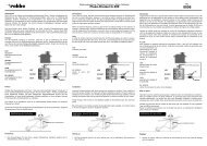
Position of servos<br />
Wire link<br />
closed<br />
open<br />
The purpose of these facilities<br />
is simply to ensure that the<br />
gyro’s stabilising effect is suppressed<br />
when the pilot gives a<br />
deliberate aileron command,<br />
and is not suppressed when the<br />
ailerons are deployed as spoilers<br />
or flaps.<br />
The aileron servos must be<br />
installed correctly if you wish to<br />
make use of these adjustment<br />
facilities. Please refer to the<br />
adjacent sketch showing a typical<br />
servo installation.<br />
5. Installing and connecting the <strong>RO</strong>-<strong>WING</strong> <strong>300</strong><br />
All gyro systems incorporating piezo sensors are sensitive to vibration. If you attempt to use<br />
a piezo gyro in a model which is subject to severe vibration, you will not achieve satisfactory<br />
results - and this applies to any piezo gyro. The strips of foam tape supplied in the set<br />
are the ideal method of mounting the gyro system in your model; good results have also<br />
been obtained with the 3.2 mm thick double-sided foam tape made by 3M (robbe Order No.<br />
5014). Suppressing vibration is important, and we advise you to take particular care over<br />
this point.<br />
Equally important is excessive heat: you should not locate the gyro close to any source of<br />
heat in the model. For example, if your model features an internal tuned pipe with inadequate<br />
shielding, the excess heat could affect the gyro system and cause an unwanted temperature<br />
drift of its neutral setting. It is also important to ensure that the mechanical linkages<br />
are free-moving and devoid of lost motion<br />
(slop).<br />
Axis of rotation<br />
Apply one of the self-adhesive strips of foam tape<br />
(supplied) to the underside of the gyro case.<br />
Install the gyro in an area of the model which is<br />
well away from sources of vibration, and which<br />
is not subject to significant temperature fluctuations.<br />
The gyro must be orientated in such a way that<br />
the axis to be stabilised runs vertically through the<br />
gyro, which corresponds to the axis of rotation of<br />
the gyro (see sketch alongside). In other words:<br />
the orientation of the gyro varies according to the<br />
axis to be stabilised.<br />
15