
You also want an ePaper? Increase the reach of your titles
YUMPU automatically turns print PDFs into web optimized ePapers that Google loves.
Bedienungsanleitung<br />
Operating instructions<br />
Notice d’utilisation<br />
<strong>RO</strong>-<strong>WING</strong> <strong>300</strong><br />
No.: 8418
1. Allgemeine Informationen<br />
Einbau- und Bedienungsanleitung<br />
Flächenkreisel <strong>RO</strong>-<strong>WING</strong>-<strong>300</strong><br />
Bestell Nr.<br />
8418<br />
Sehr geehrter Kunde, wir freuen uns, daß Sie sich für den Flächenkreisel <strong>RO</strong>-<strong>WING</strong> <strong>300</strong><br />
aus dem robbe Sortiment entschieden haben. Damit besitzen Sie ein besonders leistungsfähiges<br />
Präzisionskreiselsystem für Flächenmodelle.<br />
Trotz der relativ einfachen Handhabung dieses Flächenkreisels verlangt die Bedienung<br />
vom Anwender einige Kenntnisse. Durch diese Anleitung wird es Ihnen schnell gelingen,<br />
sich mit dem Gerät vertraut zu machen.<br />
Um dieses Ziel sicher zu erreichen, sollten Sie die Bedienungsanleitung aufmerksam lesen<br />
bevor Sie Ihren neuen Flächenkreisel in Betrieb nehmen. Wir wünschen Ihnen mit dem <strong>RO</strong>-<br />
<strong>WING</strong> <strong>300</strong> viel Freude und Erfolg.<br />
Inhaltsverzeichnis<br />
Seite<br />
1. Allgemeine Informationen 2<br />
2. Lieferumfang 3<br />
3. Technische Daten 3<br />
4. Anschlüsse und Bedienungselemente 3<br />
5. Einbau und Anschluß des <strong>RO</strong>-<strong>WING</strong> <strong>300</strong> 5<br />
Stabilisierung eines Modells um die Längsachse 6<br />
Stabilisierung eines Modells um die Querachse 7<br />
Stabilisierung eines Modells um die Hochachse 8<br />
6. Inbetriebnahme des Flächenkreisels 8<br />
Empfindlichkeitseinstellung 9<br />
Abgleich der Wirkungsrichtung 10<br />
7. Sonstige Hinweise 10<br />
Der <strong>RO</strong>-<strong>WING</strong> <strong>300</strong> von robbe mit seinem verschleißfreien Piezo-Sensor, eignet sich besonders<br />
für die Stabilisierung der Längsachse bei Modellen mit zwei Querruderservos. Sie<br />
können mit diesem Präzisionskreisel beide Servos für die beiden Querruderklappen über<br />
getrennte Kanäle ansteuern. Dadurch besteht die Möglichkeit, den Querruderausschlag zu<br />
differenzieren oder aber diese Ruder als Lande- bzw. Bremsklappen zu benutzen.<br />
Der <strong>RO</strong>-<strong>WING</strong> <strong>300</strong> verfügt über eine automatische Ausblendung des Kreisels bei Steuerbewegungen<br />
die zu einer Richtungsänderung führen. Bei der Nutzung der Querruder als<br />
Bremsklappen oder Höhenruder bleibt die stabilisierende Wirkung des Kreisels erhalten.<br />
Über einen Zusatzkanal ist die Kreiselempfindlichkeit im Bereich von 0% bis 100% stufenlos<br />
einstellbar. Bei einer Einstellung von 0% ist die Kreiselwirkung vollkommen abgeschaltet.<br />
2
Einbau- und Bedienungsanleitung<br />
Flächenkreisel <strong>RO</strong>-<strong>WING</strong>-<strong>300</strong><br />
Bestell Nr.<br />
8418<br />
Natürlich können Sie diesen Kreisel auch für die Stabilisierung der Quer- oder der<br />
Hochachse einsetzen. Sie brauchen dann nur eine Servofunktion durch den Kreisel zu<br />
‘schleifen’ und müssen das Höhen- bzw. das Seitenruderservo anschließen. Dabei muß<br />
allerdings die jeweils richtige Einbaulage berücksichtigt werden. Diese Zusammenhänge<br />
sind auf den Seiten 5 und 6 dargestellt.<br />
Ein spezielles Temperaturkompensationsverfahren sorgt für eine präzise, driftfreie Funktion<br />
des Kreisels über den gesamten Temperaturbereich. Der <strong>RO</strong>-<strong>WING</strong> <strong>300</strong> hat keine mechanischen,<br />
störanfälligen Komponenten. Er arbeitet rein elektronisch und ist damit vollkommen<br />
verschleißfrei und stets zuverlässig.<br />
2. Lieferumfang<br />
Flächenkreisel <strong>RO</strong>-<strong>WING</strong> <strong>300</strong><br />
Bedienungsanleitung<br />
zwei Paar selbstklebende Dämpfungsschaumstreifen<br />
3. Technische Daten<br />
Betriebsspannung:<br />
3 - 8 Volt am Empfängerausgang<br />
Stromaufnahme: ca. 30 mA (bei 4,8 V)<br />
Gewicht:<br />
ca. 35 g<br />
Abmessungen:<br />
41 x 41 x 20 mm<br />
Zu den Leistungsmerkmalen dieses Kreisels gehört darüber hinaus:<br />
- Einstellen der Kreiselempfindlichkeit zwischen 0% und 100% über einen Zusatzkanal<br />
am Sender<br />
- beim Einschalten wird die Knüppelstellung als Neutralpunkt bewertet<br />
- Ausblendung der vom Piloten veranlaßten Ruderbewegungen in Abhängigkeit von der<br />
Bewegungsrichtung der Querruderausschläge zueinander<br />
- Automatischer Null- bzw. Temperaturabgleich beim Einschalten<br />
- Kontroll-LED zur Anzeige der Funktionsbereitschaft<br />
- jeweils ein Servo-Reverse Schalter für beide Querruderfunktionen<br />
4. Anschlüsse und Bedienungselemente<br />
Alle Anschlüsse des <strong>RO</strong>-<strong>WING</strong> <strong>300</strong> erfolgen über besonders lange Servo-Anschlußkabel<br />
bzw. Buchsen. Damit ist Ihnen die Möglichkeit gegeben, den Kreisel an der günstigsten<br />
Stelle in Modell zu plazieren.<br />
Mit einer feinen Pinzette oder einem kleinen Schraubendreher läßt sich die Laufrichtung der<br />
Servos beider Kanäle umkehren. Dadurch können Sie das Kreiselsystem optimal an die<br />
3
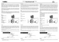
Reverse 2<br />
Reverse 1<br />
Ready LED<br />
Einbau- und Bedienungsanleitung<br />
Flächenkreisel <strong>RO</strong>-<strong>WING</strong>-<strong>300</strong><br />
Servo 1<br />
Servo 2 Rx1<br />
Drahtbrücke<br />
(Kabelschlaufe)<br />
Rx2<br />
AUX<br />
Bestell Nr.<br />
8418<br />
Konstellation Ihres Flugmodells<br />
anpassen. Die rote LED dient zur<br />
Anzeige der Betriebsbereitschaft.<br />
Sobald die Ready-LED aufleuchtet<br />
hat der Kreisel erfolgreich nach dem<br />
Einschalten automatisch den<br />
Abgleich durchgeführt und ist nun<br />
für den nächsten Flug einsatzbereit.<br />
Im einzelnen sind an diesem<br />
Kreiselsystem folgende Anschlüsse<br />
und Bedienungselemente vorhanden:<br />
- Servo 1: Anschlußbuchse für das Servo mit der Funktion 1, z.B. Querruder 1.<br />
- Servo 2: Anschlußbuchse für das Servo mit der Funktion 2, z.B. Querruder 2.<br />
- Rx 1: Kabel zum Anschluß an den Empfängerausgang mit der Funktion 1, z.B.<br />
Querruder 1.<br />
- Rx 2: Kabel zum Anschluß an den Empfängerausgang mit der Funktion 2,<br />
z.B.Querruder 2.<br />
- AUX: Kabel zum Anschluß an den Empfängerausgang über den die<br />
(Einzellitze) Empfindlichkeit des Kreisels eingestellt werden soll.<br />
- Ready LED: Kontroll-LED, zeigt die Betriebsbereitschaft an, sobald der automatische<br />
Abgleich durchgeführt wurde.<br />
- Reverse 1: Microschalter zur Umkehr der Wirkungsrichtung für die Funktion Servo 1.<br />
- Reverse 2: Microschalter zur Umkehr der Wirkungsrichtung für die Funktion Servo 2.<br />
- Drahtbrücke: Die Drahtbrücke dient zur Definition der Einbaulage der beiden<br />
Querruderservos<br />
geschlossene Brücke:<br />
Bei gleicher Bewegungsrichtung der beiden Servos ergibt sich eine<br />
Kreiselausblendung.<br />
Bei entgegengesetzter Bewegungsrichtung der beiden Servos ergibt sich<br />
keine Kreiselausblendung.<br />
offene Brücke:<br />
Bei gleicher Bewegungsrichtung der beiden Servos ergibt sich keine<br />
Kreiselausblendung.<br />
Bei entgegengesetzter Bewegungsrichtung der beiden Servos ergibt sich<br />
eine Kreiselausblendung.<br />
Zur Anpassung des <strong>RO</strong>-<strong>WING</strong> <strong>300</strong> an die jeweilige Einbaulage der beiden Querruderservos<br />
dient eine Drahtbrücke. Diese Brücke ist als ca. 2cm lange Kabelschlaufe durch die<br />
Gummitülle des Anschlußes Rx1 heraus und durch den Anschluß Servo2 wieder ins<br />
Gehäuse geführt. Wenn es die Einbaulage der Servos erfordert muß die Kabelschlaufe<br />
durchtrennt werden (offene Brücke). Beide Enden der Litze sind dann zu isolieren. Für<br />
einen anderen Einsatzzweck kann die Drahtbrücke auch wieder geschlossen werden,<br />
indem die Enden zusammen gelötet werden. Die Lötstelle muß dann gut isoliert werden.<br />
4
Einbau- und Bedienungsanleitung<br />
Flächenkreisel <strong>RO</strong>-<strong>WING</strong>-<strong>300</strong><br />
Bestell Nr.<br />
8418<br />
Einbaulage der Servos<br />
Zustand der Brücke<br />
geschlossen<br />
offen<br />
Mit diesen Einstellungen wird<br />
erreicht, daß bei Steuerbewegungen<br />
zur Richtungsänderung<br />
der Kreisel ausgeblendet<br />
wird und bei Nutzung<br />
als Bremsklappe oder Höhenruder<br />
keine Ausblendung<br />
erfolgt.<br />
Damit dieses optimal funktioniert<br />
müssen die Querruderservos<br />
richtig eingebaut werden.<br />
Beachten Sie beim Einbau<br />
der Rudermaschinen die<br />
nebenstehende Skizze.<br />
5. Einbau und Anschluß des <strong>RO</strong>-<strong>WING</strong> <strong>300</strong><br />
Alle Kreiselsysteme mit Piezo-Sensoren sind empfindlich gegen Vibrationen. In einem<br />
vibrationsbelasteten Modell werden Sie mit keinem Piezo-Kreisel zufriedenstellende<br />
Ergebnisse erzielen. Mit den beiliegenden Schaumstoffteilen können Sie das Kreiselsystem<br />
auf Ihr Modell anpassen. Gute Ergebnisse wurden auch mit dem 3,2 mm dicken<br />
Doppelklebeband von 3M (robbe Bestell - Nr. 5014) erzielt. Wir empfehlen Ihnen deshalb<br />
dringend, diesem Punkt besondere Aufmerksamkeit zu schenken.<br />
Ebenso sollten Sie den Kreisel nicht in der Nähe von Wärmequellen im Modell plazieren.<br />
Durch die Wärmebelastungen, die z.B. von einem nur unzureichend abgeschirmten<br />
Resonanzrohr im Rumpf ausgeht, kann es zu einer ungewollten Temperaturdrift des<br />
Systems kommen. Achten Sie auch auf spielfreie und leichtgängige<br />
Gestängeverbindungen.<br />
Drehachse des Kreisels<br />
Kleben Sie einen der mitgelieferten selbstklebenden<br />
Schaumstoffstreifen auf die Unterseite des<br />
Kreisel - Gehäuses.<br />
Plazieren Sie das Gehäuse nun an einer vibrationsarmen<br />
Stelle im Modell, die keinen oder nur<br />
sehr geringen Temperaturschwankungen ausgesetzt<br />
ist.<br />
Der Kreisel ist so einzubauen, daß die zu stabilisierende<br />
Achse senkrecht durch den Kreisel verläuft.<br />
Sie stimmt dann mit der Drehachse des<br />
Kreisel überein (siehe nebenstehende Skizze.<br />
Der Einbau hängt deshalb von der zu stabilisierenden<br />
Achse ab.<br />
5
Einbau- und Bedienungsanleitung<br />
Flächenkreisel <strong>RO</strong>-<strong>WING</strong>-<strong>300</strong><br />
Stabilisierung eines Modells um die Längsachse<br />
Bestell Nr.<br />
8418<br />
Das wichtigste Einsatzgebiet des <strong>RO</strong>-<strong>WING</strong><br />
<strong>300</strong> ist die Stabilisierung um die Längsachse<br />
in einem Flächenmodell mit zwei Querruderservos.<br />
Dazu ist der Kreisel mit zwei unabhängigen<br />
Ein- und Ausgängen ausgerüstet.<br />
Für beide Servofunktionen kann die Wirkungsrichtung<br />
getrennt umgeschaltet werden.<br />
Ist in einem Flugmodell nur ein Querruderservo<br />
eingebaut, bleibt der zweite Anschluß<br />
frei.<br />
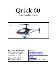
Für diesen hauptsächlichen Verwendungszweck<br />
ist der Anschluß an den Empfänger<br />
aus der nebenstehdenden Skizze ersichtlich.<br />
Das Anschlußkabel ‘Rx 1’ verbinden Sie mit<br />
dem Kanal 1 am Empfänger (Querruder 1 bei<br />
robbe/Futaba Systemen). Das Anschlußkabel<br />
‘Rx 2’ verbinden Sie bitte mit<br />
1<br />
dem Kanal 5, 6, oder 7 (Querruder 2 bei<br />
Receiver<br />
2<br />
3<br />
robbe/Futaba Systemen, je nach Mischprogramm)<br />
am Empfänger. Die beiden Servos<br />
4<br />
5<br />
6<br />
7<br />
8<br />
verbinden Sie mit den zugehörigen<br />
Ausgängen des Kreisels. Das Anschlußkabel<br />
‘AUX’ schließen Sie an einen<br />
Empfängerausgang, dem ein Schieberegler zugeordnet ist , an.<br />
35 MHz<br />
Der Einbau des Kreisels zur Stabilisierung der<br />
Längsachse geht aus der Skizze hervor.<br />
Das Bild zeigt die Einbaulage des <strong>RO</strong>-<strong>WING</strong><br />
<strong>300</strong> in einem Flächenmodell. Diese Lage muß<br />
unbedingt eingehalten werden.<br />
Die Drehachse des Kreisels muß parallel zur<br />
Längsachse des Modells eingebaut werden.<br />
Gut untergebracht ist der Kreisel im Schwerpunktbereich<br />
des Rumpfes, weil er hier nahe an<br />
der zu überwachenden Achse positioniert ist.<br />
Bei der Stabilisierung von ungewollten<br />
Drehbewegungen um die Längsachse durch den <strong>RO</strong>-<strong>WING</strong> <strong>300</strong> müssen Sie beim Einsatz<br />
von zwei Servos für die Querruderfunktion unbedingt darauf achten, daß die Einbaulage<br />
der beiden Servos mit dem Zustand der Drahtbrücke “Einbaulage der beiden<br />
Querruderservos” übereinstimmt.<br />
6
Einbau- und Bedienungsanleitung<br />
Flächenkreisel <strong>RO</strong>-<strong>WING</strong>-<strong>300</strong><br />
Bestell Nr.<br />
8418<br />
Der <strong>RO</strong>-<strong>WING</strong> <strong>300</strong> ist kein Autopilot, der eine vorgegebene Höhe und einen festgelegten<br />
Kurs einhält. Er mißt die Drehrate um eine Achse und ist bestrebt, diese Drehrate so schnell<br />
wie möglich zu eliminieren.<br />
Der Einsatz dieses Kreisels in einem Flächenmodell zur Stabilisierung der Längsachse<br />
bringt für den Anwender eine Reihe von Vorteilen. Bei böigem Wetter ist der <strong>RO</strong>-<strong>WING</strong> <strong>300</strong><br />
Kreisel eine große Hilfe, weil er zuverlässiger und ohne Reaktionszeit auf ungewollte<br />
Bewegungen des Modells um die Längsachse reagiert. Wenn eine plötzliche Böe eine<br />
Seite der Tragfläche anhebt, steuert der Kreisel schnell und kräftig dagegen, so daß der<br />
Pilot von den Windverhältnissen so gut wie nichts merkt. Besonders beim Start und bei der<br />
Landung wirkt sich der Einfluß eines Kreisels, wegen der Turbulenzen in Bodennähe,<br />
besonders positiv aus. Das Modell liegt wesentlich ruhiger in der Luft und entwickelt kaum<br />
noch ein ‘Eigenleben’.<br />
Mit einem <strong>RO</strong>-<strong>WING</strong> <strong>300</strong> an den Querrudern kann bei Seglern mit keiner oder nur geringer<br />
V-Form das Kreisflugverhalten wesentlich verbessert werden, so daß auch mit solchen<br />
Modellen ein entspanntes Kreisen in der Thermik möglich wird. Der Kreisel hält die Schräglage<br />
der Tragfläche fest und verhindert, daß der Segler aus dem Bart heraus dreht. Bei der<br />
Thermiksuche sollte man die Empfindlichkeit des Kreisels stark reduzieren. Der Pilot will<br />
am Anheben einer Flächenhälfte einen Aufwind erkennen. Ein empfindlicher Kreisel würde<br />
dieses verhindern. Hat man aber Thermik gefunden wirkt sich ein Kreisel positiv auf das<br />
Flugverhalten aus.<br />
Beim Seglerschlepp hat der Einsatz eines Kreisel zur Folge, daß der Schleppzug wesentlich<br />
ruhiger und damit vorbildähnlicher in der Luft liegt. Die Piloten können sich mehr auf<br />
das Fliegen, als auf das Aussteuern von Böen konzentrieren. Das gleiche gilt auch für den<br />
Einsatz des <strong>RO</strong>-<strong>WING</strong> <strong>300</strong> bei der Flugschulung.<br />
Stabilisierung eines Modells um die Querachse<br />
Der Einsatz des <strong>RO</strong>-<strong>WING</strong> <strong>300</strong> in einem Flächenmodell zur Stabilisierung der Querachse<br />
bringt für den Anwender neben dem bereits beschriebenen Vorgang, der automatischen<br />
Aussteuerung von äußeren Einflüssen durch Turbulenzen, weitere spezifische Vorteile.<br />
Lastigkeitsänderungen um die Querachse, wie<br />
sie z.B. durch das Setzen von Wölb-, Bremsoder<br />
Störklappen hervorgerufen werden, gleicht<br />
der Kreisel automatisch aus.<br />
Das sonst typische Aufbäumen oder Abtauchen<br />
des Modells bei gesetzten Klappen, z.B. beim<br />
Landeanflug eines Seglers, wird verhindert. Eine<br />
Höhen- oder Tiefenruderbetätigung ist nicht<br />
nötig. Der Einbau des Kreisels zur Stabilisierung<br />
der Querachse geht aus der Skizze hervor.<br />
7
Einbau- und Bedienungsanleitung<br />
Flächenkreisel <strong>RO</strong>-<strong>WING</strong>-<strong>300</strong><br />
Bestell Nr.<br />
8418<br />
Das Bild zeigt die Einbaulage des <strong>RO</strong>-<strong>WING</strong> <strong>300</strong> in einem Flächenmodell. Diese Lage muß<br />
unbedingt eingehalten werden. Die Drehachse des Kreisels muß parallel zur Querachse<br />
des Modells eingebaut werden. Gut untergebracht ist der Kreisel im Schwerpunktbereich<br />
des Rumpfes, weil er hier nahe an der zu überwachenden Achse positioniert ist.<br />
Für diesen Einsatzzweck muß das Höhenruderservo (Kanal 2 bei robbe/Futaba) über die<br />
Funktion 1 durch den Kreisel geschliffen werden. Der zweite Ein- und Ausgang bleibt frei.<br />
Der Anschluß “AUX” wird mit einem freien Kanal verbunden.<br />
Stabilisierung eines Modells um die Hochachse<br />
Der Einbau des Kreisels zur Stabilisierung der<br />
Hochachse geht aus der Skizze hervor.<br />
Das Bild zeigt die Einbaulage des <strong>RO</strong>-<strong>WING</strong><br />
<strong>300</strong> in einem Flächenmodell. Diese Lage muß<br />
unbedingt eingehalten werden. Die Drehachse<br />
des Kreisels muß parallel zu der zur Hochachse<br />
des Modells eingebaut werden. Gut untergebracht<br />
ist der Kreisel im Schwerpunktbereich<br />
des Rumpfes, weil er hier nahe an der zu überwachenden<br />
Achse positioniert ist.<br />
Für diesen Einsatzzweck muß das<br />
Seitenruderservo (Kanal 4 bei robbe/Futaba) über die Funktion 1 durch den Kreisel<br />
geschleift werden. Der zweite Ein- und Ausgang bleibt frei. Der Anschluß “AUX” wird mit<br />
einem freien Kanal verbunden.<br />
Der Einsatz des <strong>RO</strong>-<strong>WING</strong> <strong>300</strong> in einem Flächenmodell zur Stabilisierung der Hochachse<br />
bringt für den Anwender neben dem oben bereits beschriebenen Vorgang, der automatischen<br />
Aussteuerung von äußeren Einflüssen durch Turbulenzen, weitere spezifische<br />
Vorteile. Ein Kreisel verbessert das Bodenstartverhalten von Flugmodellen entscheidend.<br />
Das Ausbrechen des Modells z. B. bei Seitenwind wird unterdrückt. Mit einem gut abgestimmten<br />
Kreisel starten die Modelle ‘wie auf Schienen’.<br />
6. Inbetriebnahme des Flächenkreisels<br />
Bauen Sie den <strong>RO</strong>-<strong>WING</strong> <strong>300</strong> wie beschrieben für den jeweiligen Einsatzzweck in Ihrem<br />
Modell ein und schließen Sie ihn wie dargestellt an. Danach schalten Sie den Sender und<br />
anschließend den Empfänger ein. Nach dem Einschalten der Spannungsversorgung führt<br />
der Kreisel einen ca. 10 Sekunden dauernden Abgleich durch. Voraussetzung für einen ordnungsgemäßen<br />
Abschluß dieses wichtigen Vorganges ist es, daß der Kreisel während dieser<br />
Zeit nicht bewegt wird. Das Modell muß still auf dem Boden stehen und darf nicht<br />
berührt werden. Das Ende des Nullabgleichs wird durch das Aufleuchten der Ready-LED<br />
angezeigt. Sollte das Modell trotzdem bewegt worden sein, oder die Kontroll-LED blinken,<br />
8
Einbau- und Bedienungsanleitung<br />
Flächenkreisel <strong>RO</strong>-<strong>WING</strong>-<strong>300</strong><br />
Bestell Nr.<br />
8418<br />
muß zur erneuten Initialisierung die Empfängerstromversorgung aus - und wieder eingeschaltet<br />
werden. Das gleiche gilt, wenn nach dem Abgleich Parameter geändert werden,<br />
indem z.B. durch einen der Microschalter die Wirkungsrichtung umgekehrt wird. Auch dann<br />
ist ein neuer Abgleich nötig, damit sich der <strong>RO</strong>-<strong>WING</strong> <strong>300</strong> auf die neue Konstellation einstellen<br />
kann.<br />
Empfindlichkeitseinstellung<br />
Vom Sender aus kann über einen Zusatzkanal die Empfindlichkeit des <strong>RO</strong>-<strong>WING</strong> <strong>300</strong> eingestellt<br />
werden. Dazu muß wie oben beschrieben der Anschluß ‘AUX’ mit dem Empfänger<br />
verbunden werden. Dabei sollten Sie einen freien Kanal wählen dem ein Schieberegler<br />
zugeordnet ist. Damit haben Sie die Möglichkeit, die Kreiselwirkung individuell an jede Flugund<br />
Wetterlage während des Einsatzes anzupassen.<br />
Die Kreiselempfindlichkeit ist zwischen 0% und 100% stufenlos einstellbar. Bei 0%<br />
Kreiselempfindlichkeit ist die stabilisierende Wirkung des Kreisels ausgeschaltet. Damit Sie<br />
die maximale Kreiselempfindlichkeit nutzen können, darf keine Servowegbegrenzung programmiert<br />
sein, bzw. es muß sichergestellt werden, daß die angegebenen Servoweggrenzen<br />
erreicht werden. Bei Knüppelbewegungen zur Richtungsänderung wird die Kreiselempfindlichkeit<br />
in Abhängigkeit von der Größe der Steuerbewegung verringert.<br />
100 %<br />
Die nebenstehende Abbildung zeigt einen Schieberegler<br />
eines Senders, der zur Einstellung der Empfindlichkeit<br />
benutzt werden kann. Stellen Sie durch Bewegen des<br />
Modells und Beobachten der Kreiselwirkung fest, an<br />
welcher Schiebereglerposition 0% bzw. 100% erreicht<br />
wird.<br />
Die genaue Einstellung der richtigen Wirkung des <strong>RO</strong>-<br />
<strong>WING</strong> <strong>300</strong> ist stark vom eingesetzten Modell abhängig.<br />
Für den ersten Flugeinsatz sollte die Empfindlichkeit<br />
beim Start auf 0% eingestellt werden. Nach Erreichen<br />
einer gewissen Sicherheitshöhe wird dann die<br />
Empfindlichkeit vorsichtig aufgeregelt. Ergibt sich im<br />
LINEAR 0 % anschließenden Flug eine Überreaktion, d. h. das Modell<br />
ist um die zu kontrollierende Achse sehr nervös, es dreht<br />
hin- und her und kommt nicht zur Ruhe, muß die<br />
Empfindlichkeit so lange zurück genommen werden, bis sich eine ruhiges Flugverhalten<br />
einstellt.<br />
Kommt dagegen die automatische Reaktion auf eine ungewollte Bewegung sehr schwach<br />
und langsam, sollte die Empfindlichkeit erhöht werden. Die richtige Grundeinstellung läßt<br />
sich auf diese Art und Weise innerhalb eines Fluges ermitteln.<br />
Dabei ist es möglich, bei anderen Wetterlagen und Flugsituationen die Empfindlichkeit zu<br />
verändern, um das Flugverhalten zu optimieren.<br />
9
Einbau- und Bedienungsanleitung<br />
Flächenkreisel <strong>RO</strong>-<strong>WING</strong>-<strong>300</strong><br />
Bestell Nr.<br />
8418<br />
Beim Start und bei der Landung kann die Wirkung des Kreisels unter Umständen leicht<br />
erhöht werden. Bei den häufig auftretenden Turbulenzen in Bodennähe werden Sie die<br />
Unterstützung durch den <strong>RO</strong>-<strong>WING</strong> <strong>300</strong> besonders schätzen lernen.<br />
Abgleich der Wirkungsrichtung<br />
Vor dem ersten Einsatz müssen Sie unbedingt die Wirkungsrichtung des Kreisels testen,<br />
da es sonst im Flugbetrieb statt zu einer Kompensation der störenden Einflüsse zu einer<br />
Verstärkung kommt. Voraussetzung für die Überprüfung ist, daß am Sender alle<br />
Einstellungen richtig vorgenommen wurden. Stellen Sie die Empfindlichkeit auf 100%. Alle<br />
Servos müssen ohne Kreisel die richtige Drehrichtung aufweisen.<br />
Bei dieser Kontrolle wird das Modell bei eingeschalteter Anlage um die durch den <strong>RO</strong>-<br />
<strong>WING</strong> <strong>300</strong> zu stabilisierende Achse hin und her gedreht. Dabei muß die Reaktion des/der<br />
entsprechenden Ruderklappen beobachtet werden. Drehen sich diese in eine die<br />
Bewegung behindernde Richtung ist die Einstellung in Ordnung. Würden die Ausschläge<br />
dagegen die Bewegung des Modells verstärken, muß die Wirkungsrichtung des Ruders<br />
bzw. der Ruderklappe, die falsch reagiert, umgedreht werden.<br />
Wenn der Kreisel z.B. zur Stabilisierung der Längsachse eingesetzt wird, bewegen Sie das<br />
Modell bitte um diese Achse. Drehen Sie es in Flugrichtung gesehen nach rechts, muß der<br />
Kreisel mit einer Querruderbewegung nach links dagegen wirken. Die linke Querruderklappe<br />
muß kurzzeitig nach oben, die rechte nach unten ausschlagen.<br />
Sollte ein oder beide Ruder eine entgegengesetzte Reaktion zeigen, kann mit dem entsprechenden<br />
Microschalter die Wirkungsrichtung umgedreht werden. Die Laufrichtung der<br />
Servos im Sender darf nicht verändert werden. Benutzen Sie dazu bitte einen kleinen<br />
Schraubendreher oder eine feine Pinzette. Eine Servoumkehr im klassischen Sinne wird<br />
dadurch nicht erreicht. Die Funktion bezieht sich ausschließlich auf die Richtung der<br />
Reaktion des Kreisel auf eine ungewollte Drehbewegung des Modells um die zu kontrollierende<br />
Achse.<br />
7. Sonstige Hinweise<br />
Als verantwortungsbewußter Pilot sollten Sie vor jedem Start die Wirkungsweise des<br />
Kreisels kontrollieren. So wie Sie sich es sicher angewöhnt haben einen Rudercheck<br />
durchzuführen, sollten Sie kurz testen ob auch der Kreisel richtig funktioniert.<br />
Beim Einsatz eines empfindlichen Kreisels wie dem <strong>RO</strong>-<strong>WING</strong> <strong>300</strong>, der zwei Servos<br />
ansteuert, ist mit einem höherem Bedarf an elektrischer Energie zu rechnen. Der Kreisel<br />
sorgt dafür, daß die beiden Querruderservos permanent arbeiten und dabei Strom aus dem<br />
Akku entnehmen. Bei ausgedehnten Thermikflügen, bei längeren Hangflugeinsätzen, aber<br />
auch wenn an einem Tag viele Flüge durchgeführt werden sollen, muß eine entsprechende<br />
Akkukapazität im Modell vorgehalten werden. Sie können aber auch zwischen den<br />
Flügen den Akku mit einem entsprechenden Ladegerät aus der Autobatterie nachladen.<br />
10
Einbau- und Bedienungsanleitung<br />
Flächenkreisel <strong>RO</strong>-<strong>WING</strong>-<strong>300</strong><br />
Bestell Nr.<br />
8418<br />
Beim Einsatz des Kreisels in einem Elektroflugmodell empfiehlt es sich, eine Position zu<br />
wählen, die nicht in unmittelbarer Nähe zu den stromführenden Kabeln liegt. Die relativ starken<br />
elektromagnetischen Felder der Leitungen könnten auf den Kreisel einwirken. Genau<br />
das gleiche gilt für Zündkabel beim Einsatz von großvolumigen Benzinmotoren.<br />
Wenn Sie den <strong>RO</strong>-<strong>WING</strong> <strong>300</strong> an einer Fernlenkanlage betreiben die im PCM-Modus arbeitet,<br />
sollten Sie folgendes beachten. Der Eingang Rx1 muß an einen Empfängerausgang mit<br />
niedriger Kanalnummer als Rx2 angeschlossen werden. Der Prozessor des Kreisels kann<br />
die Signale der beiden Querruderkanäle nur verarbeiten, wenn sie zeitlich nacheinander<br />
und nicht gleichzeitig eintreffen. Bei einem PPM-System sind die einzelnen Kanäle stets in<br />
genügend großem zeitlichem Abstand hintereinander angeordnet, so daß in dieser Hinsicht<br />
keine Probleme auftreten können. Beim robbe/Futaba PCM-System mit den Kanälen 1 und<br />
5, 6 oder 7 für die beiden Querruder ergeben sich ebenfalls keinerlei Probleme. Bitte prüfen<br />
Sie ob das von Ihnen eingesetzte PCM-Verfahren diesen Ansprüchen genügt.<br />
Der Einbau des Kreisels muß sorgfältig vorgenommen werden, um zu verhindern, daß er<br />
sich löst und einen Absturz zur Folge hat. Eine individuelle Einstellung der Kreiselausblendung<br />
bei Querruderbetätigung ist durch einen Mischer von Querruder auf “AUX”<br />
möglich.<br />
Die Anlenkung der Ruder sollte möglichst spielfrei und leichtgängig sein, dadurch wird<br />
höhere Präzision und geringerer Stromverbrauch erreicht. Beim Einsatzdes Kreisels in<br />
schnellen oder kleinen Modellen (Turbinenmodellen) muss die Kreiselempfindlichkeit sehr<br />
gering sein, da sonst die Gefahr besteht, dass durch Aufschwingen der Querruder das<br />
Modell überlastet wird.<br />
robbe Modellsport GmbH & Co. KG<br />
Technische Änderungen vorbehalten<br />
11
obbe Modellsport GmbH & Co. KG<br />
Metzloserstr. 36<br />
36355 Grebenhain<br />
Tel: 06644 87-0<br />
robbe Form 40-4578 JJJ
1. Introduction<br />
Operating instructions<br />
Gyro <strong>RO</strong>-<strong>WING</strong>-<strong>300</strong><br />
Order No.<br />
8418<br />
Dear customer,<br />
Congratulations on your choice of the <strong>RO</strong>-<strong>WING</strong> <strong>300</strong> fixed-wing gyro from the robbe range<br />
of electronic equipment. You are now the owner of a highly effective, high-performance precision<br />
gyro system designed for fixed-wing model aircraft.<br />
This fixed-wing gyro is relatively easy to set up and handle, but nevertheless operating it<br />
successfully does call for some understanding on the part of the user. These instructions<br />
are designed to help you become familiar with the unit quickly.<br />
You can avoid frustration by reading right through these operating instructions attentively<br />
before you attempt to use your new fixed-wing gyro. We hope you have many hours of pleasure<br />
and success with your <strong>RO</strong>-<strong>WING</strong> <strong>300</strong>.<br />
Contents<br />
Page<br />
1. General information 12<br />
2. Set contents 13<br />
3. Specification 13<br />
4. Connections and controls 13<br />
5. Installing and connecting the <strong>RO</strong>-<strong>WING</strong> <strong>300</strong> 15<br />
Stabilising a model aircraft around the longitudinal (roll) axis 16<br />
Stabilising a model aircraft around the lateral (pitch) axis 17<br />
Stabilising a model aircraft around the vertical (yaw) axis 18<br />
6. Using the fixed-wing gyro for the first time 18<br />
Sensitivity (gain) adjustment 19<br />
Setting the direction of gyro effect 20<br />
7. Supplementary notes 20<br />
The robbe <strong>RO</strong>-<strong>WING</strong> <strong>300</strong> features a zero-wear piezo-sensor, and its primary function is to<br />
stabilise the aileron function in models with two separate aileron servos. This precision gyro<br />
system can control both the servos which drive the ailerons via separate channels. This<br />
enables you to apply differential aileron travel, or use the ailerons as landing flaps or spoilers.<br />
The <strong>RO</strong>-<strong>WING</strong> <strong>300</strong> automatically suppresses its stabilising effect when it detects a deliberate<br />
control command, i.e. when the pilot dictates a change in the model’s direction. If a<br />
mixer is applied to the ailerons, and the pilot gives a command relating to their use as spoilers<br />
or flaps, the stabilising effect of the gyro is not suppressed. If a supplementary channel<br />
is available, you can vary gyro sensitivity (gain) over the full range of 0% to 100%. At the<br />
0% setting the gyro effect is switched off completely.<br />
12
Operating instructions<br />
Gyro <strong>RO</strong>-<strong>WING</strong>-<strong>300</strong><br />
Order No.<br />
8418<br />
Of course, you can also use this gyro to stabilise a fixed-wing model around the lateral<br />
(pitch) or vertical (yaw) axis. In this case you only need to loop one servo function through<br />
the gyro, and connect the elevator or rudder servo to the gyro. The piezo gyro must be<br />
installed in the correct orientation relative to the axis to be stabilised. Pages 15 and 16 provide<br />
full details of this.<br />
The gyro features a special temperature compensation circuit which ensures that the gyro<br />
operates accurately, without drift problems, over the full temperature range.<br />
The <strong>RO</strong>-<strong>WING</strong> <strong>300</strong> has no mechanical components which would be vulnerable to damage<br />
or failure. It is entirely electronic in operation, and is therefore completely reliable and not<br />
subject to wear.<br />
2. Contents of set<br />
<strong>RO</strong>-<strong>WING</strong> <strong>300</strong> fixed-wing gyro<br />
Operating instructions<br />
Two pairs of self-adhesive absorbent foam strips<br />
3. Specification:<br />
Operating voltage:<br />
3 - 8 Volts from receiver output<br />
Current drain: approx. 30 mA (at 4.8 V)<br />
Weight:<br />
approx. 35 g<br />
Dimensions:<br />
41 x 41 x 20 mm<br />
Further performance features of this gyro:<br />
- Gyro gain adjustment within the range 0% to 100% via auxiliary transmitter channel<br />
- When switched on, the gyro adopts the current stick position as its neutral point<br />
- Gyro suppression when the pilot gives an aileron control command, but not when both<br />
ailerons are moved in the same direction<br />
- Automatic zero point and temperature calibration when gyro is switched on<br />
- Monitor LED to indicate “ready” state<br />
- Servo reverse switches for both aileron functions<br />
4. Connections and controls<br />
The <strong>RO</strong>-<strong>WING</strong> <strong>300</strong> is fitted with extra-long servo and socket leads, which makes it easy for<br />
you to install the gyro in the most favourable location in the model.<br />
You can reverse the direction of rotation of either or both servos by means of switches, operated<br />
using fine-tip tweezers or a small screwdriver.<br />
This feature makes it simple to set up the gyro system to suit the existing servo arrangement<br />
in your model aircraft. The red monitor LED indicates when the gyro is ready to use.<br />
13
Reverse 2<br />
Reverse 1<br />
Servo 1<br />
Operating instructions<br />
Gyro <strong>RO</strong>-<strong>WING</strong>-<strong>300</strong><br />
Servo 2 Rx1<br />
Rx2<br />
AUX<br />
Order No.<br />
8418<br />
The “Ready” LED lights up when the<br />
gyro has successfully completed its<br />
automatic self-calibration process<br />
after being switched on; it is then<br />
immediately ready for the next flight.<br />
The following connections and controls<br />
are present on this gyro<br />
system:<br />
Ready LED<br />
Wire link<br />
(loop of wire)<br />
- Servo 1: Socket for the function 1 servo, e.g. aileron 1.<br />
- Servo 2: Socket for the function 2 servo, e.g. aileron 2.<br />
- Rx 1: Cable for connection to receiver output 1, e.g. aileron 1.<br />
- Rx 2: Cable for connection to receiver output 2, e.g. aileron 2.<br />
- AUX: Cable for connection to the receiver output which controls<br />
[single wire] gyro gain<br />
- Ready LED: Monitor LED, shows that the gyro is ready for use when the automa<br />
tic self-calibration process has been completed.<br />
- Reverse 1: Micro-switch for reversing the direction of servo 1.<br />
- Reverse 2: Micro-switch for reversing the direction of servo 2.<br />
- Wire link: The link is used when required by the physical orientation of the two<br />
aileron servos.<br />
Closed link:<br />
Gyro suppression in force when both servos are moved in the same<br />
direction.<br />
Gyro suppression not in force when servos are moved in opposite<br />
directions.<br />
Open link:<br />
Gyro suppression not in force when both servos are moved in the<br />
same direction<br />
Gyro suppression in force when the servos are moved in opposite<br />
directions.<br />
The <strong>RO</strong>-<strong>WING</strong> <strong>300</strong> features a wire link whose purpose is to set up the gyro to suit the orientation<br />
of the two aileron servos. The link takes the form of a loop of wire about 2 cm long<br />
which emerges through the rubber grommet of the Rx1 cable, and enters the case through<br />
the Servo 2 grommet. If the installed position of the servos requires it, you must cut through<br />
the loop of wire (open link).<br />
Both ends of the wire should then be insulated. If a different model requires the opposite<br />
arrangement (closed link), you can solder the cut ends together; if you do this you must<br />
insulate the soldered joint carefully.<br />
14
Operating instructions<br />
Gyro <strong>RO</strong>-<strong>WING</strong>-<strong>300</strong><br />
Order No.<br />
8418<br />
Position of servos<br />
Wire link<br />
closed<br />
open<br />
The purpose of these facilities<br />
is simply to ensure that the<br />
gyro’s stabilising effect is suppressed<br />
when the pilot gives a<br />
deliberate aileron command,<br />
and is not suppressed when the<br />
ailerons are deployed as spoilers<br />
or flaps.<br />
The aileron servos must be<br />
installed correctly if you wish to<br />
make use of these adjustment<br />
facilities. Please refer to the<br />
adjacent sketch showing a typical<br />
servo installation.<br />
5. Installing and connecting the <strong>RO</strong>-<strong>WING</strong> <strong>300</strong><br />
All gyro systems incorporating piezo sensors are sensitive to vibration. If you attempt to use<br />
a piezo gyro in a model which is subject to severe vibration, you will not achieve satisfactory<br />
results - and this applies to any piezo gyro. The strips of foam tape supplied in the set<br />
are the ideal method of mounting the gyro system in your model; good results have also<br />
been obtained with the 3.2 mm thick double-sided foam tape made by 3M (robbe Order No.<br />
5014). Suppressing vibration is important, and we advise you to take particular care over<br />
this point.<br />
Equally important is excessive heat: you should not locate the gyro close to any source of<br />
heat in the model. For example, if your model features an internal tuned pipe with inadequate<br />
shielding, the excess heat could affect the gyro system and cause an unwanted temperature<br />
drift of its neutral setting. It is also important to ensure that the mechanical linkages<br />
are free-moving and devoid of lost motion<br />
(slop).<br />
Axis of rotation<br />
Apply one of the self-adhesive strips of foam tape<br />
(supplied) to the underside of the gyro case.<br />
Install the gyro in an area of the model which is<br />
well away from sources of vibration, and which<br />
is not subject to significant temperature fluctuations.<br />
The gyro must be orientated in such a way that<br />
the axis to be stabilised runs vertically through the<br />
gyro, which corresponds to the axis of rotation of<br />
the gyro (see sketch alongside). In other words:<br />
the orientation of the gyro varies according to the<br />
axis to be stabilised.<br />
15
Operating instructions<br />
Gyro <strong>RO</strong>-<strong>WING</strong>-<strong>300</strong><br />
Order No.<br />
8418<br />
Stabilising a model aircraft around the longitudinal (roll) axis<br />
The primary application for the <strong>RO</strong>-<strong>WING</strong><br />
<strong>300</strong> is to stabilise a fixed-wing model with two<br />
aileron servos around the longitudinal (roll)<br />
axis. For this application the gyro features<br />
two independent inputs and outputs, and the<br />
direction of effect can be reversed separately<br />
for each function. If only one aileron servo is<br />
fitted in the model aircraft, the second<br />
connector is simply left unused.<br />
The adjacent drawing shows the receiver<br />
connections for this primary application.<br />
35 MHz<br />
Receiver<br />
1<br />
2<br />
3<br />
4<br />
5<br />
6<br />
7<br />
8<br />
Connect the cable marked ‘RX 1’ to receiver<br />
channel 1 (Aileron 1 in robbe/Futaba<br />
systems). Connect the cable marked ‘Rx 2’ to<br />
receiver channel 5, 6 or 7 (aileron 2 in<br />
robbe/Futaba systems, according to mixer<br />
program). Connect the two servos to the<br />
appropriate gyro outputs. Connect the cable<br />
marked ‘AUX’ to a receiver output which is<br />
controlled by a slider on the transmitter.<br />
The sketch shows the method of installing the gyro to provide stabilisation around the roll<br />
axis.<br />
The picture shows the orientation of the <strong>RO</strong>-<br />
<strong>WING</strong> <strong>300</strong> in a fixed-wing model aircraft. It is<br />
absolutely essential that you keep to this position.<br />
In this case the rotational axis of the gyro must<br />
be installed parallel to the longitudinal axis<br />
(fuselage centreline) of the model. We recommend<br />
that you install the gyro in the fuselage<br />
close to the CG, because that places it close to<br />
the axis which is to be monitored and stabilised.<br />
If you wish the <strong>RO</strong>-<strong>WING</strong> <strong>300</strong> to stabilise the model against unwanted rotational movements<br />
around the longitudinal axis, and if you are using two servos for the aileron function,<br />
it is absolutely essential that the state of the wire link is appropriate to the orientation of the<br />
two servos; this is described under “Connections and controls”.<br />
16
Operating instructions<br />
Gyro <strong>RO</strong>-<strong>WING</strong>-<strong>300</strong><br />
Order No.<br />
8418<br />
The <strong>RO</strong>-<strong>WING</strong> <strong>300</strong> is not an auto-pilot; it does not maintain a given altitude and a pre-determined<br />
heading. Instead it measures the rate of rotational movement around one axis and<br />
attempts to eliminate this rotation as rapidly as possible.<br />
Using this gyro in a fixed-wing model in order to stabilise the longitudinal axis provides<br />
many benefits to the pilot. In gusty weather the <strong>RO</strong>-<strong>WING</strong> <strong>300</strong> gyro is a great help, because<br />
it responds with complete reliability to unwanted movements of the model around the<br />
longitudinal axis, and without any significant lag in response time. If a sudden gust of wind<br />
lifts one wing, the gyro quickly and decisively counteracts that movement, so that the pilot<br />
often does not even notice that a gust has occurred. At take-off time and on landing the<br />
influence of a gyro is particularly useful, as air turbulence is very common close to the ground.<br />
If you are used to “fighting” the model onto the ground, you will immediately notice that<br />
the model is much smoother, and seems to be flying in completely neutral air.<br />
If you install the <strong>RO</strong>-<strong>WING</strong> <strong>300</strong> in an aileron-equipped glider with little or no dihedral, you<br />
can expect a marked improvement in the model’s circling characteristics; often to the extent<br />
that a “difficult” model is transformed into one which circles smoothly and easily in a thermal,<br />
with little effort from the pilot. The gyro reliably maintains the wing’s angle of bank and<br />
prevents the glider tending to turn away from the rising air. However, when searching for<br />
thermals you should reduce the gain of the gyro to a low level, as you will want to detect lift<br />
by watching for one wing to rise, and the gyro will prevent this happening if the gain is high.<br />
Once you have found your thermal, increase the gain, and the gyro will have the expected<br />
positive effect on the model’s handling.<br />
If you wish to aero-tow a glider, fitting the <strong>RO</strong>-<strong>WING</strong> <strong>300</strong> makes for a much smoother tow,<br />
which also looks far more realistic in the air. The two pilots can now concentrate fully on the<br />
flying, without having to worry about compensating for gusts. Similar advantages are apparent<br />
when using a gyro-equipped trainer.<br />
Stabilising a model aircraft around the lateral (pitch) axis<br />
Installing the <strong>RO</strong>-<strong>WING</strong> <strong>300</strong> in a fixed-wing model aircraft with the aim of stabilising the lateral<br />
axis provides several specific advantages in addition to the standard one of automatically<br />
compensating for external influences and turbulence.<br />
The gyro can automatically compensate for pitch<br />
trim changes due to the deflection of camberchanging<br />
flaps, airbrakes or spoilers.<br />
When flaps or brakes are deployed, e.g. when a<br />
glider is on the landing approach, the model<br />
often balloons up or dives, but the gyro prevents<br />
this happening, and eliminates the need for corrective<br />
elevator input. The method of installing<br />
the gyro to stabilise the lateral axis is shown in<br />
the sketch.<br />
17
Operating instructions<br />
Gyro <strong>RO</strong>-<strong>WING</strong>-<strong>300</strong><br />
Order No.<br />
8418<br />
The picture shows the orientation of the <strong>RO</strong>-<strong>WING</strong> <strong>300</strong> in a fixed-wing model aircraft. It is<br />
absolutely essential that you keep to this position. The rotational axis of the gyro must be<br />
installed parallel to the lateral axis (wingspan) of the model. We recommend that you install<br />
the gyro in the fuselage close to the CG, because that places it close to the axis which is<br />
to be monitored and stabilised.<br />
For this application the elevator servo (channel 2 in robbe/Futaba systems) must be looped<br />
through the gyro via function 1. The second input and output are left unused. The “AUX”<br />
cable can be connected to any free channel.<br />
Stabilising a model aircraft around the vertical axis<br />
The method of installing the gyro to stabilise the<br />
yaw axis is shown in the sketch.<br />
The picture shows the orientation of the <strong>RO</strong>-<br />
<strong>WING</strong> <strong>300</strong> in a fixed-wing model aircraft. It is<br />
absolutely essential that you keep to this position.<br />
The rotational axis of the gyro must be installed<br />
parallel to the yaw (vertical) axis of the<br />
model. We recommend that you install the gyro<br />
in the fuselage close to the CG, because that<br />
places it close to the axis which is to be monitored<br />
and stabilised.<br />
For this application the rudder servo (channel 4 in robbe/Futaba systems) must be looped<br />
through the gyro via function 1. The second input and output are left unused. The “AUX”<br />
cable can be connected to any free channel.<br />
Installing the <strong>RO</strong>-<strong>WING</strong> <strong>300</strong> in a fixed-wing model aircraft with the aim of stabilising the yaw<br />
axis provides several specific advantages in addition to the standard one of automatically<br />
compensating for external influences and turbulence. The gyro provides a crucial improvement<br />
in the take-off behaviour of model aircraft. In a side-wind any fixed-wing model tends<br />
to shear off to one side, but the gyro suppresses this unwanted movement effectively. With<br />
a well set-up gyro your model will take off as if on rails.<br />
6. Using the fixed-wing gyro for the first time<br />
Install the <strong>RO</strong>-<strong>WING</strong> <strong>300</strong> in the model as described for your particular application, and<br />
connect it as shown in these instructions. Switch on the transmitter and then the receiving<br />
system. When you switch on the power supply, the gyro carries out a self-calibration process<br />
which lasts about 10 seconds. If the gyro is to complete this process accurately and<br />
without errors, it is absolutely essential that you do not move the gyro during this calibration<br />
period. Leave the model standing motionless on the ground, and do not touch it at all.<br />
The “Ready” LED lights up to signal the end of the zero calibration process. However, if the<br />
model is moved, or if the monitor LED flashes, the calibration process fails. You must then<br />
18
Operating instructions<br />
Gyro <strong>RO</strong>-<strong>WING</strong>-<strong>300</strong><br />
Order No.<br />
8418<br />
switch the receiver power supply off and on again, so that the gyro is initialised anew. The<br />
same applies if you alter any parameters after the self-calibration process has been completed;<br />
for instance, if you reverse the direction of gyro effect using one of the micro-switches.<br />
In that case you also need to repeat the self-calibration, so that the <strong>RO</strong>-<strong>WING</strong> <strong>300</strong><br />
can adjust itself to suit the new arrangement.<br />
Adjusting gyro sensitivity (gain)<br />
The gain of the <strong>RO</strong>-<strong>WING</strong> <strong>300</strong> can be adjusted from the transmitter by means of an auxiliary<br />
channel. To use this facility you should connect the cable marked “AUX” to the receiver,<br />
using a vacant channel which is assigned to a slider control on the transmitter. This gives<br />
you the means to adjust the gyro effect while you are flying the model, to suit fluctuating<br />
flight conditions and weather.<br />
The gain of the gyro can be set to any value within the range 0% - 100%. At 0% gain the<br />
stabilising effect of the gyro is switched off completely. If you wish to exploit maximum gyro<br />
sensitivity, it is important to switch off any servo travel reduction on the auxiliary channel,<br />
i.e. you should check that full servo travel is available for the gyro gain channel. When you<br />
move the stick to effect a change in the model’s heading, the gain of the gyro is reduced in<br />
proportion to the magnitude of the command.<br />
LINEAR<br />
100 %<br />
0 %<br />
The illustration alongside shows a transmitter slider set<br />
up to adjust gyro gain. You can determine the slider positions<br />
which correspond to 0% and 100% gain by moving<br />
the model and watching the effect of the gyro’s response.<br />
The optimum setting for the gain of the <strong>RO</strong>-<strong>WING</strong> <strong>300</strong><br />
varies greatly according to the model in which it is installed.<br />
For the first few flights we suggest that you set gyro<br />
gain to 0% before launch. Take the model up to a safe<br />
altitude before carefully advancing gyro gain. If you find<br />
that the gyro over-reacts, i.e. the model becomes very<br />
twitchy around the axis to be controlled, moving constantly<br />
to and fro and never staying in one attitude, reduce<br />
gyro gain until the model is flying smoothly.<br />
If the opposite effect occurs, i.e. the gyro’s automatic response to an unwanted movement<br />
is very weak and slow, increase gyro gain gradually. In this way you can generally find the<br />
optimum basic setting in a single flight.<br />
Although you have now set the basic gain level, it is always possible to adjust the gyro’s<br />
sensitivity to suit different weather conditions and flight situations, i.e. you can optimise the<br />
model’s flying characteristics to suit the prevailing conditions.<br />
At take-off and landing you may find it helpful to increase the effect of the gyro under certain<br />
circumstances. Air turbulence is very common close to the ground, and you will soon<br />
19
Operating instructions<br />
Gyro <strong>RO</strong>-<strong>WING</strong>-<strong>300</strong><br />
learn to appreciate the support provided by the <strong>RO</strong>-<strong>WING</strong> <strong>300</strong> in this situation.<br />
Order No.<br />
8418<br />
Setting the direction of gyro effect<br />
Before you use the <strong>RO</strong>-<strong>WING</strong> <strong>300</strong> for the first time it is absolutely essential to check the<br />
direction of effect of the gyro. If set incorrectly, the gyro will still respond to disturbances,<br />
but will amplify them instead of correcting them. This test can only be carried out successfully<br />
once you have completed all the settings at the transmitter. Check that all the servos<br />
rotate in the correct direction when the gyro is switched off. Now set the gyro gain to 100%.<br />
For this check switch the model on and rotate it to and fro around the axis which the <strong>RO</strong>-<br />
<strong>WING</strong> <strong>300</strong> is intended to stabilise. Watch the response of the control surface or surfaces<br />
very closely. The gyro is set correctly when the control surface deflects in the direction<br />
which counteracts the movement. However, if the control surface deflects in the direction<br />
which would amplify the model’s movement, you must reverse the direction of gyro effect<br />
on the control surface or surfaces which responds incorrectly.<br />
For example, if you have set up the gyro to stabilise the longitudinal axis, rotate the model<br />
around this axis: twist the fuselage to roll the model to the right, as seen from the tail looking<br />
forward, and the gyro should respond by giving a left aileron movement, i.e. the lefthand<br />
aileron should rise briefly, the right-hand aileron fall briefly.<br />
If one or both control surfaces exhibits the opposite reaction, reverse the direction of gyro<br />
effect on that servo by operating the corresponding micro-switch. Do not reverse the direction<br />
of rotation of the servo or servos at the transmitter. The switches can be operated using<br />
a small screwdriver or a fine pair of tweezers. Note that these switches do not reverse the<br />
servo in the conventional sense; the function refers exclusively to the direction of response<br />
of the gyro to an unwanted rotational movement of the model around the axis to be controlled.<br />
7. Supplementary notes<br />
As a responsible pilot you should check the direction of effect of the gyro before each flight.<br />
As part of the pre-flight check all pilots ensure that the control surfaces are operating normally,<br />
but you should now check that the gyro is working properly at the same time.<br />
When you are using a sensitive gyro like the <strong>RO</strong>-<strong>WING</strong> <strong>300</strong> to control two servos, you must<br />
expect an increase in the airborne system’s consumption of electrical energy. The effect of<br />
the gyro is that both aileron servos work almost constantly, and therefore draw current from<br />
the receiver battery at a rapid rate. If you enjoy extended thermal flights, protracted sessions<br />
of slope flying, or just like to carry out a large number of flights in a single session, you<br />
must provide adequate battery capacity in the model. However, a perfectly good alternative<br />
is to recharge the receiver battery between flights, using a suitable field charger powered<br />
by your car battery.<br />
If you are using the gyro in an electric-powered model aircraft, we recommend that you sel-<br />
20
Operating instructions<br />
Gyro <strong>RO</strong>-<strong>WING</strong>-<strong>300</strong><br />
Order No.<br />
8418<br />
ect a position which is not in the immediate vicinity of cables carrying very high currents.<br />
These cables generate relatively powerful electro-magnetic fields, which could have an<br />
adverse effect on the gyro. Precisely the same applies to ignition cables if your model is<br />
powered by a large-capacity petrol engine.<br />
If you wish to use the <strong>RO</strong>-<strong>WING</strong> <strong>300</strong> in conjunction with a radio control system operating in<br />
PCM mode, please note the following point: input Rx1 must be connected to a receiver output<br />
with a lower channel number than Rx2. The gyro’s processor can only process the signals<br />
for the two aileron channels if there is a distinct interval between them, i.e. they must<br />
not arrive simultaneously. With a PPM system the individual channels are sent in sequence,<br />
and the interval between signals is long enough to eliminate any problems which might<br />
arise. With robbe/Futaba PCM systems you will be using channel 1 with channel 5, 6 or 7<br />
for the two ailerons, and in this case you will also encounter no problems at all. Please<br />
check that the PCM process used by your RC system satisfies these conditions.<br />
If the gyro comes loose in its mountings, the model is virtually bound to crash, and for this<br />
reason the gyro must be installed carefully. It is possible to vary the rate of gyro suppression<br />
when you operate the aileron control by assigning a mixer between the aileron and<br />
“AUX” channels.<br />
The linkage to the control surfaces must be as direct (slop-free) and free-moving as possible,<br />
as this improves overall precision and reduces current drain. If you are using the gyro<br />
in a small or high-speed model (turbine models), it is important to set the gyro gain to a very<br />
low level, otherwise the ailerons may oscillate and overload the airframe.<br />
robbe Modellsport GmbH & Co. KG<br />
We reserve to alter technical specifications<br />
21
1. Informations générales<br />
Notice d’utilisation<br />
Gyroscope <strong>RO</strong>-<strong>WING</strong>-<strong>300</strong><br />
Réf.<br />
8418<br />
Nous nous réjouissons que vous ayez opté pour un gyroscope de voilure <strong>RO</strong>-<strong>WING</strong> <strong>300</strong><br />
présent dans la gamme robbe. Vous disposez ainsi d’un système gyroscopique performant<br />
de haute précision pour les modèles à aile fixe.<br />
Malgré la grande maniabilité de ce gyroscope de voilure, sa mise en œuvre exige du pilote<br />
un certain nombre de connaissances. La présente notice vous permettra de vous familiariser<br />
rapidement avec cet appareil.<br />
Pour atteindre cet objectif, liez attentivement la notice avant d’employer votre nouveau<br />
gyroscope. Nous vous souhaitons beaucoup de plaisir et de succès avec votre <strong>RO</strong>-<strong>WING</strong><br />
<strong>300</strong>.<br />
Sommaire<br />
Page<br />
1. Informations générales 22<br />
2. Contenu du kit 23<br />
3. Caractéristiques techniques 23<br />
4. Connexions et éléments de commande 23<br />
5. Mise en place et branchement du <strong>RO</strong>-<strong>WING</strong> <strong>300</strong> 25<br />
Stabilisation d’un modèle dans l’axe longitudinal 26<br />
Stabilisation d’un modèle dans l’axe transversal 27<br />
Stabilisation d’un modèle dans l’axe vertical 28<br />
6. Mise en service du gyroscope d’aile 28<br />
Réglage de sa sensibilité 29<br />
Équilibrage du sens d’efficacité 30<br />
7. Autres indications 30<br />
Le gyroscope <strong>RO</strong>-<strong>WING</strong> <strong>300</strong> de robbe avec sont capteur piézo exempt d’usure est particulièrement<br />
conçu pour la stabilisation de l’axe longitudinal de modèles équipés de deux<br />
servos d’ailerons.<br />
Avec ce gyroscope de précision vous avez la possibilité de piloter les deux ailerons à partir<br />
de deux voies autonomes. Vous avez ainsi la possibilité d’établir un différentiel au niveau<br />
du débattement des ailerons ou de les utiliser comme des volet d’atterrissage ou des<br />
aérofreins.<br />
Le gyroscope <strong>RO</strong>-<strong>WING</strong> <strong>300</strong> dispose d’une discrimination automatique de son efficacité en<br />
présence de mouvements de pilotage qui conduisent à un changement de direction.<br />
Lorsque les ailerons sont utilisés comme des aérofreins ou comme gouverne de profondeur,<br />
l’effet de stabilisation du gyroscope est maintenue. Une voie supplémentaire permet<br />
de régler la sensibilité du gyroscope sur une gamme de 0 à 100 %, en continu. Lorsque ce<br />
réglage est sur 0, l’efficacité du gyroscope est parfaitement nulle.<br />
22
Notice d’utilisation<br />
Gyroscope <strong>RO</strong>-<strong>WING</strong>-<strong>300</strong><br />
Réf.<br />
8418<br />
Naturellement, il est également possible d’utiliser ce gyroscope pour la stabilisation des axe<br />
transversal et vertical. Il vous suffit alors de “rectifier” une seule fonction de servo par le<br />
gyroscope et raccorder le servo de profondeur et le servo de direction. Il faut toutefois, dans<br />
ce cas, tenir compte de son implantation dans le modèle. Ces relations sont présentée<br />
pages 25 et2 6 de cette notice.<br />
Un processus spécifique de compensation de la température assure la précision et l’absence<br />
de dérive de la fonction du gyroscope quelle que soit la température. Le gyroscope<br />
<strong>RO</strong>-<strong>WING</strong> <strong>300</strong> ne comprend pas d’éléments susceptibles de subir des pannes. Il travaille<br />
de manière absolument électronique et donc sans usure et son efficacité est constante.<br />
2. Contenu du kit<br />
Gyroscope de voilure <strong>RO</strong>-<strong>WING</strong> <strong>300</strong><br />
Mode d’emploi<br />
deux paires de bandes auto-adhésives de mousse<br />
3. Caractéristiques techniques<br />
Tension de service:<br />
Consommation:<br />
Poids:<br />
Encombrement:<br />
3 à 8 volts, sortie du récepteur<br />
approx. 30 mA (à 4,8 volts)<br />
approx. 35 g<br />
41 x 41 x 20 mm<br />
Les caractéristiques de ce gyroscope se résument ainsi:<br />
- Réglage en continu de la sensibilité du gyroscope entre 0 et 100 % à partir d’une voie de<br />
l’émetteur<br />
- Lors de la mise en marche, la position des manches est prise comme référence du neutre.<br />
- Discrimination des mouvements engagés par le pilote indépendamment du sens du mouvement<br />
mutuel du débattement des ailerons.<br />
- Compensation automatique du zéro et de la température à la mise sous tension.<br />
- Voyant à LED pour l’affichage de l’ordre de marche.<br />
- Un inverseur de la course du servo pour chacun des ailerons.<br />
4. Connexions et éléments de commande<br />
Les connexions du <strong>RO</strong>-<strong>WING</strong> <strong>300</strong> sont assurées par des cordons de servo ou des douilles<br />
particulièrement longs. Il est possible de choisir ainsi la position idéale du gyroscope dans<br />
le modèle.<br />
Avec une pincette fine ou un petit tournevis, il est possible d’inverser le sens de déplacement<br />
des servos des deux voies. Ainsi vous avez la possibilité d’adapter avec une grande<br />
précision le système gyroscopique à la structure pilote de votre modèle. La LED rouge<br />
23
Reverse 2<br />
Reverse 1<br />
Servo 1<br />
Notice d’utilisation<br />
Gyroscope <strong>RO</strong>-<strong>WING</strong>-<strong>300</strong><br />
Servo 2 Rx1<br />
Rx2<br />
Réf.<br />
8418<br />
assure l’affichage de l’ordre de marche.<br />
Dès que la LED d’ordre de<br />
marche s’allume le gyroscope a<br />
réussi après sa mise sous tension<br />
un équilibre automatique et il est<br />
prêtre pour le prochain vol.<br />
Ready LED<br />
Cavalier<br />
(Boucle de fil)<br />
AUX<br />
En détail, le gyroscope est pourvu<br />
des éléments de connexion et de<br />
commande suivants:<br />
- Servo 1: douille de connexion du servo de la fonction 1, par exemple aileron 1.<br />
- Servo 2: douille de connexion du servo de la fonction 2, par exemple aileron 2.<br />
- Rx1: cordon de raccordement à la sortie de l’émetteur de la fonction 1, par<br />
exemple aileron 1.<br />
- Rx2: cordon de raccordement à la sortie de l’émetteur de la fonction 2, par<br />
exemple aileron 2.<br />
- AUX: (brin unique) fil de raccordement à la sortie du récepteur qui permet<br />
de régler la sensibilité du gyroscope.<br />
- LED d’ordre LED de contrôle de l’ordre de marche dès que le calibrage automde<br />
marche tique est intervenu<br />
- Reverse 1: microcommutateur pour l’inversion du sens de l’efficacité de la fonction<br />
du servo 1.<br />
- Reverse 2: microcommutateur pour l’inversion du sens de l’efficacité de la fonction<br />
du servo 2.<br />
- Cavalier: le cavalier permet de définir la position d’implantation des deux servos<br />
d’ailerons:<br />
- cavalier fermé:<br />
lorsque le sens du mouvement est identique pour les deux servos,<br />
intervient une discrimination.<br />
lorsque le sens du mouvement est opposé pour les deux servos, n’intervient<br />
pas de discrimination.<br />
- cavalier ouvert:<br />
lorsque le sens du mouvement est identique pour les deux servos,<br />
n’intervient pas de discrimination.<br />
lorsque le sens du mouvement est opposé pour les deux servos,<br />
intervient une discrimination.<br />
Pour adapter le gyroscope <strong>RO</strong>-<strong>WING</strong> <strong>300</strong> à l’implantation des deux servos d’aileron, ont<br />
utilise un cavalier. Ce cavalier est une boucle de fil de 2 cm de long environ conduisant par<br />
le Silentbloc du raccord Rx1 vers l’extérieur et par le raccord Servo2 à nouveau dans le<br />
boîtier. Lorsque la position d’implantation des servos l’exige, il faut couper le cavalier (l’ou-<br />
24
Notice d’utilisation<br />
Gyroscope <strong>RO</strong>-<strong>WING</strong>-<strong>300</strong><br />
Réf.<br />
8418<br />
Position des servos<br />
Cavalier<br />
fermé<br />
ouvert<br />
vrir). Il faut dans ce cas isoler<br />
les deux extrémités du brin.<br />
Pour une autre application il<br />
est également possible de<br />
refermer le cavalier en ressoudant<br />
les deux extrémité. Il faut<br />
dans ce cas parfaitement isoler<br />
la soudure.<br />
Ces réglages permettent, en<br />
présence de mouvements pilotes<br />
engageant un changement<br />
de direction, de discriminer le<br />
gyroscope alors que lorsque<br />
les ailerons sont utilisés<br />
comme aérofreins ou comme<br />
gouverne de profondeur, la discrimination intervient.<br />
Afin que le principe fonctionne parfaitement, il faut que les servos d’aileron soient parfaitement<br />
montés. Tenir compte du schéma ci-contre pour la mise en place des gouvernes.<br />
5. Mise en place et branchement du <strong>RO</strong>-<strong>WING</strong> <strong>300</strong><br />
Tous les systèmes gyroscopiques avec capteurs piézo sont sensibles aux vibrations. Dans<br />
un modèle présentant des vibrations particulièrement fortes, aucun gyroscope piézo électrique<br />
ne vous donnera satisfaction. Les éléments de mousse plastique autocollante jointe<br />
vous permettent d’adapter le système gyroscopique à votre modèle. Il est également<br />
possible d’obtenir de bons résultats avec du ruban adhésif double face de la Sté 3M (réf.<br />
robbe 8014). Nous vous recommandons dans tous les cas d’apporter une grande attention<br />
à cet aspect de la mise en place. Il faut également éviter impérativement d’installer le gyroscope<br />
dans le modèle à un emplacement où la chaleur est intense. La chaleur fournie par<br />
exemple par un résonateur dont l’isolation est insuffisante dans le fuselage risque de provoquer<br />
la dérive thermique du système. Veiller également à ce que les tringles se déplacent<br />
sans jeu.<br />
Axe de rotation du gyroscope<br />
Coller l’un des morceaux de mousse autocollante<br />
sous le boîtier du gyroscope.<br />
Installer le gyroscope à un endroit du fuselage<br />
exempt de vibrations et ne présentant pas de<br />
variations de température, ou à la rigueur de très<br />
faibles variations de température.<br />
Implanter le gyroscope de telle sorte que l’axe à<br />
stabiliser se trouver perpendiculaire au gyroscope.<br />
Il coïncide alors parfaitement avec l’axe de<br />
rotation du gyroscope (cf. schéma ci-contre). La<br />
mise en place du gyroscope est donc conditionnée<br />
par l’axe qu’il doit stabiliser.<br />
25
Notice d’utilisation<br />
Gyroscope <strong>RO</strong>-<strong>WING</strong>-<strong>300</strong><br />
Réf.<br />
8418<br />
Stabilisation d’un modèle dans l’axe longitudinal<br />
Le domaine d’application essentiel du gyroscope<br />
<strong>RO</strong>-<strong>WING</strong> <strong>300</strong> est la stabilisation de<br />
l’axe longitudinal dans un modèle à voilure<br />
fixe avec deux servos d’aileron. Pour ce faire,<br />
le gyroscope est pourvu de deux sortie et entrée<br />
indépendantes. Pour les deux fonctions<br />
de servo il est possible d’inverser séparément<br />
le sens de rotation. Dans un modèle<br />
équipé d’un seul servo d’aileron, le second<br />
raccord reste libre.<br />
35 MHz<br />
Receiver<br />
1<br />
2<br />
3<br />
4<br />
5<br />
6<br />
7<br />
8<br />
Pour cette mise en œuvre essentielle, le raccordement<br />
au récepteur est présenté sur le<br />
schéma ci-contre.<br />
Raccorder le cordon de connexion “Rx1” à la<br />
voie 1 du récepteur (aileron 1 sur le système<br />
robbe Futaba). Le cordon de connexion<br />
“Rx2” doit être relié à la voie 5, 6 ou 7 (aileron<br />
2 sur le système robbe Futaba, en fonction<br />
du système de mixage) du récepteur.<br />
Raccorder les deux servos avec les sorties<br />
correspondantes du gyroscope. Raccorder le<br />
cordon de connexion “AUX” à la sortie du<br />
récepteur solidaire d’un curseur.<br />
La mise en place du gyroscope pour la stabilisation<br />
de l’axe longitudinal est présentée par le<br />
schéma.<br />
Le schéma présente la position d’implantation<br />
du gyroscope <strong>RO</strong>-<strong>WING</strong> <strong>300</strong> dans un modèle à<br />
voilure fixe. Ce position doit absolument être<br />
respectée.<br />
L’axe de rotation du gyroscope doit être parallèle<br />
à l’axe longitudinal du modèle. Le gyroscope<br />
est parfaitement installé lorsqu’il se trouve<br />
dans le secteur du centre de gravité du fuselage<br />
car il se trouve ainsi à proximité de l’axe qu’il<br />
doit surveiller.<br />
Lorsque le gyroscope <strong>RO</strong>-<strong>WING</strong> <strong>300</strong> stabilise des mouvement de rotation non souhaités<br />
sur l’axe longitudinal, il faut, en présence de deux servos pour les ailerons veiller à ce que<br />
la position d’implantation du gyroscope soit mise au point avec les deux cavaliers “mise en<br />
place en présence de deux servos d’aileron”.<br />
26
Notice d’utilisation<br />
Gyroscope <strong>RO</strong>-<strong>WING</strong>-<strong>300</strong><br />
Réf.<br />
8418<br />
Le système <strong>RO</strong>-<strong>WING</strong> <strong>300</strong> n’est pas un pilote automatique qui préserve une certaine hauteur<br />
et un cap déterminés. Il mesure les taux de rotation autour d’un axe et s’efforce d’éliminer<br />
le plus vite possible ce taux de rotation.<br />
La mise en œuvre de ce gyroscope dans les modèles à voilure fixe pour la stabilisation de<br />
l’axe longitudinal présente un certain nombre d’avantages. Lorsque le vent souffle en rafales,<br />
le gyroscope <strong>RO</strong>-<strong>WING</strong> <strong>300</strong> et d’un grand secours pour compenser les mouvements<br />
involontaires du modèle autour de l’axe longitudinal sans délai de réaction. Lorsqu’une rafale<br />
de vent soudaine soulève un côté de l’aile, le gyroscope réagit promptement et vigoureusement<br />
de telle sorte que le pilote ne constate pratiquement pas l’effet des sautes du<br />
vent. Particulièrement au décollage et à l’atterrissage l’efficacité du gyroscope est remarquable<br />
à cause des turbulences à l’approche du sol. Le modèle vole de manière beaucoup<br />
plus stable sans présenter tendances à l’”autodétermination”.<br />
Avec le gyroscope <strong>RO</strong>-<strong>WING</strong> <strong>300</strong> sur les ailerons, il est possible d’améliorer nettement le<br />
comportement en voltige des planeurs ne disposant pas de dièdre ou d’un dièdre très<br />
réduit, de telle sorte que le modèle soit en mesure de spiraler sans difficulté dans les thermiques.<br />
Le gyroscope préserve l’inclinaison de l’aile et empêche que sorte de la bulle. Pour<br />
la recherche des thermiques il est recommandé de réduire fortement la sensibilité du<br />
gyroscope. Le pilote veut être en mesure de détecteur une bulle à l’élévation d’une demiaile.<br />
Un gyroscope très sensible supprimerait cette réaction du modèle. Lorsque la bulle a<br />
été détectée, le gyroscope agit de manière positive sur le comportement en vol.<br />
Lorsqu’un planeur est remorqué, le gyroscope lui procure un vol remorqué nettement plus<br />
stable et son aspect en vol correspond parfaitement aux planeurs grandeur. Le pilote a plus<br />
de temps pour d’occuper du pilotage et peut ignorer les sautes de vent. La même efficacité<br />
est à souligner pour le pilotage accompagné (instructeur-élève) assisté par le gyroscope<br />
<strong>RO</strong>-<strong>WING</strong> <strong>300</strong>.<br />
Stabilisation d’un modèle dans l’axe transversal<br />
La mise en œuvre du gyroscope <strong>RO</strong>-<strong>WING</strong> <strong>300</strong> sur les modèles à voilure fixe pour la stabilisation<br />
de l’axe transversal donne au pilote, outre les avantages déjà décrits précédemment,<br />
la compensation automatique des incidences extérieures causées par des turbulences.<br />
Les décalages de charges autour de l’axe transversal,<br />
causés par exemple par la mise en<br />
œuvre des volets de courbure, des aérofreins ou<br />
des déporteurs sont compensés automatiquement<br />
par le gyroscope.<br />
On évite ainsi les cabrages ou le piqué typique à<br />
l’atterrissage lors de la mise en œuvre des volets<br />
d’un planeur. Il n’est pas nécessaire d’intervenir<br />
au niveau de la profondeur. La mise en place du<br />
27
Notice d’utilisation<br />
Gyroscope <strong>RO</strong>-<strong>WING</strong>-<strong>300</strong><br />
Réf.<br />
8418<br />
gyroscope pour la stabilisation de l’axe transversal est présentée sur le schéma ci-contre.<br />
Le schéma présente la mise en place du gyroscope <strong>RO</strong>-<strong>WING</strong> <strong>300</strong> dans un modèle à voilure<br />
fixe. Cette position d’implantation doit être absolument respectée. L’axe de rotation du<br />
gyroscope doit être parallèle à l’axe transversal du modèle. Le gyroscope est parfaitement<br />
installé lorsqu’il se trouve près du centre de gravité du fuselage parce qu’il se trouve alors<br />
à proximité de l’axe à surveiller.<br />
Dans ce cas de mise en œuvre, le servo de profondeur (voie 2 sur les ensembles robbe<br />
Futaba) doit être rectifié par la fonction 1 du gyroscope. Les secondes entrée et sortie<br />
restent libres. Le raccord “AUX” est raccordé à une voie non affectée.<br />
Stabilisation d’un modèle dans l’axe vertical<br />
La mise en place du gyroscope pour la stabilisation<br />
de l’axe vertical est présentée sur le schéma<br />
ci-contre.<br />
Le présente la position d’implantation du gyroscope<br />
<strong>RO</strong>-<strong>WING</strong> <strong>300</strong> dans un modèle à voilure<br />
fixe. Cette position d’implantation doit être absolument<br />
respectée. L’axe de rotation du gyroscope<br />
doit être parallèle à l’axe vertical du modèle.<br />
Le gyroscope est parfaitement installé lorsqu’il<br />
se trouve près du centre de gravité du fuselage<br />
parce qu’il se trouve alors à proximité de l’axe à surveiller.<br />
Dans ce cas de mise en œuvre, le servo de direction (voie 4 sur les ensembles robbe<br />
Futaba) doit être rectifié par la fonction 1 du gyroscope. Les secondes entrée et sortie<br />
restent libres. Le raccord “AUX” est raccordé à une voie non affectée.<br />
La mise en œuvre de ce gyroscope dans les modèles à voilure fixe pour la stabilisation de<br />
l’axe vertical présente un certain nombre d’avantages. Lorsque le vent souffle en rafales, le<br />
gyroscope <strong>RO</strong>-<strong>WING</strong> <strong>300</strong> et d’un grand secours pour compenser les mouvements involontaires<br />
du modèle autour de l’axe longitudinal sans délai de réaction. Lorsqu’une rafale de<br />
vent soudaine soulève un côté de l’aile, le gyroscope réagit promptement et vigoureusement<br />
de telle sorte que le pilote ne constate pratiquement pas l’effet des sautes du vent. La<br />
mise en œuvre du gyroscope <strong>RO</strong>-<strong>WING</strong> <strong>300</strong> sur les modèles à voilure fixe pour la stabilisation<br />
de l’axe transversal donne au pilote, outre les avantages déjà décrits précédemment,<br />
la compensation automatique des incidences extérieures causées par des turbulences.<br />
Lorsque le gyroscope est parfaitement au point, le modèle se déplace comme sur des<br />
“rails”.<br />
6. Mise en service du gyroscope d’aile<br />
Installer le gyroscope <strong>RO</strong>-<strong>WING</strong> <strong>300</strong> comme décrit en fonction des spécificités de sa mise<br />
28
Notice d’utilisation<br />
Gyroscope <strong>RO</strong>-<strong>WING</strong>-<strong>300</strong><br />
Réf.<br />
8418<br />
en œuvre dans votre modèle et le raccorder comme indiqué. Mettre ensuite l’émetteur en<br />
marche puis le récepteur. Après la mise sous tension, le gyroscope réalise d’abord un calibrage<br />
pendant 10 secondes environ. Condition préalable à ce calibrage: le gyroscope ne<br />
doit pas être déplacé pendant cette période. Le modèle doit être au repos au sol et ne doit<br />
pas être touché. À la fin du calibrage à zéro l’ordre de marche est signalé par le fait que la<br />
LED d’ordre de marche s’allume. Si malgré tout le modèle a été déplacé ou que la LED d’ordre<br />
de marche clignote, il faut refaire une initialisation en coupant le récepteur et l’émetteur<br />
avant de les remettre en marche. La même procédure s’impose lorsqu’au cours du calibrage<br />
un paramètre est modifié. Par exemple lorsqu’une inversion intervient au niveau d’un<br />
microcommutateur de direction. Dans ce cas également il faut reprendre le calibrage afin<br />
que le gyroscope <strong>RO</strong>-<strong>WING</strong> <strong>300</strong> soit en mesure de s’ajuster à sa tâche.<br />
Réglage de sa sensibilité<br />
À partir de l’émetteur il est possible, à l’aide d’une voie complémentaire de régler la sensibilité<br />
du gyroscope <strong>RO</strong>-<strong>WING</strong> <strong>300</strong>. Pour ce faire, comme décrit ci-dessus, il faut relier<br />
“AUX” au récepteur. Sélectionner une voie libre pilotée par un curseur. Vous avez ainsi la<br />
possibilité, pendant le vol, quelle que soit l’assiette de vol, de corriger l’efficacité du gyroscope.<br />
La sensibilité du gyroscope est réglable progressivement entre 0 et 100 %. À 0%, le gyroscope<br />
est inefficace au niveau de la stabilisation. Afin de<br />
pouvoir exploiter la sensibilité maximale du gyroscope, il<br />
100 %<br />
ne faut pas programmer de limitation de course des servos<br />
ou bien, il faut s’assurer que les limites de débattement<br />
des servos dont atteintes. Lorsque les manches<br />
sont déplacés pour un changement de direction, l’incidence<br />
de la correction du gyroscope est modifiée en<br />
fonction de l’importance des mouvements pilotés.<br />
LINEAR<br />
0 %<br />
Le schéma ci-contre présente le curseur d’un émetteur<br />
destiné au réglage de la sensibilité. En déplaçant le<br />
modèle et en observant l‘efficacité du gyroscope définie<br />
la position du curseur correspondant à 0 % puis à 100<br />
%.<br />
Le réglage de précision de l’efficacité du gyroscope <strong>RO</strong>-<strong>WING</strong> <strong>300</strong> dépend essentiellement<br />
du modèle dans lequel il est mis en œuvre. Pour le premier vol, disposer la sensibilité du<br />
gyroscope sur 0 % avant le décollage. Après avoir atteint une altitude de sécurité, mettre<br />
avec précaution la sensibilité au point. Si, dans la poursuite du vol, le modèle présente des<br />
réactions extrêmement vives sur l’axe monitoré par le gyroscope, effectue des mouvement<br />
incontrôlés sans se calmer, il faut réduire la sensibilité du gyroscope jusqu’à ce que le comportement<br />
en vol du modèle soit correct.<br />
Si, par contre, la réaction automatique du gyroscope sur un mouvement incontrôlé se mon-<br />
29
Notice d’utilisation<br />
Gyroscope <strong>RO</strong>-<strong>WING</strong>-<strong>300</strong><br />
Réf.<br />
8418<br />
tre très faible et lente, il faut augmenter la sensibilité du gyroscope. Il est ainsi possible<br />
d’établir le réglage initial correct au cours de la première sortie avec gyroscope.<br />
Il est toutefois possible de modifier la sensibilité du gyroscope en fonctions des incidences<br />
de la météo ou des situations de vol afin d’optimiser le comportement du modèle.<br />
Au décollage et à l’atterrissage, selon les circonstances, il est possible d’augmenter légèrement<br />
la sensibilité du gyroscope. Lorsque des turbulences apparaissent fréquemment à<br />
l’approche du sol, l’assistance apportée par le gyroscope <strong>RO</strong>-<strong>WING</strong> <strong>300</strong> vous sera d’une<br />
grande utilité.<br />
Équilibrage du sens d’efficacité<br />
Avant sa première mise en œuvre, il est indispensable de vérifier le sens de l’efficacité du<br />
gyroscope, sinon il risque, au cours du vol, d’accroître les effets parasites au lieu de les<br />
contrer. Condition préalable au contrôle : il faut que tous les réglages corrects aient été définis<br />
sur l’émetteur. Disposer la sensibilité du gyroscope sur 100 %. Tous les servos doivent<br />
se déplacer dans le bon sens sans l’intervention du gyroscope.<br />
Pour effectuer le contrôle, effectuer un mouvement de va-et-vient avec le modèle autour de<br />
l’axe que le gyroscope <strong>RO</strong>-<strong>WING</strong> <strong>300</strong> stabilise. Ce faisant, observer la réaction du ou des<br />
gouvernes ou volets correspondants. Si ceux-ci se déplacent dans une direction contrant<br />
le mouvement, le réglage est au point. Si les débattements renforcent le mouvement du<br />
modèle, il faut inverser le sens de l’efficacité de la gouverne ou des volets dont la réaction<br />
est incorrecte.<br />
Lorsque la gyroscope est par exemple mis en œuvre pour stabiliser l’axe longitudinal,<br />
déplacer le modèle autour de cet axe. Si vous le déplacez vers la droite, vu dans le sens<br />
du vol, il faut que le gyroscope réagisse avec un déplacement des ailerons vers la gauche.<br />
L’aileron gauche doit présenter un débattement bref vers le haut, le droit vers le bas.<br />
Si un ou les deux ailerons présentent une réaction opposée, il est possible d’inverser le<br />
sens d’efficacité avec le microcommutateur approprié. Ne pas modifier le sens de rotation<br />
des servos sur l’émetteur. Pour ce faire, utiliser un petit tournevis ou une pincette fine. Il ne<br />
s’agit donc pas d’une inversion de la course du servo dans le sens classique de la notion.<br />
La fonction se rapporte exclusivement à la direction de la réaction du gyroscope sur un<br />
mouvement rotatif du modèle autour de l’axe à stabiliser.<br />
7. Autres indications<br />
Un pilote conscient de sa responsabilité doit effectuer un contrôle du sens de l’efficacité du<br />
gyroscope avant chaque vol. Tous comme vous avez l’habitude de vérifier systématiquement<br />
les gouvernes, il faut contrôler rapidement le fonctionnement du gyroscope.<br />
Pour la mise en œuvre d’un gyroscope sensible comme le <strong>RO</strong>-<strong>WING</strong> <strong>300</strong> pour la stabilisation<br />
de 2 servos, il faut s’attendre à une consommation électrique nettement accrue. Le<br />
30
Notice d’utilisation<br />
Gyroscope <strong>RO</strong>-<strong>WING</strong>-<strong>300</strong><br />
Réf.<br />
8418<br />
gyroscope veille à ce que les deux servos d’aileron travaillent en permanence et prélèvent<br />
dont de la capacité de l’accu. Pour des vols thermiques prolongés ou de longues séances<br />
de vol de pente, mais également les jours ou de nombreux vols successifs sont réalisés, il<br />
faut se réserver une certaine quantité de courant de l’accu dans le modèle. Il est également<br />
possible, entre deux vols, de recharger l’accu avec un chargeur approprié à partir d’une batterie<br />
de voiture.<br />
Pour la mise en œuvre d’un gyroscope dans un modèle à entraînement électrique, il est<br />
recommandé de l’implanter loin des brins du cordon d’alimentation électrique. Les champs<br />
magnétiques relativement importants des cordons sont susceptibles de présenter une incidence<br />
sur le gyroscope. Il en va de même pour le cordon d’alimentation de la bougie sur<br />
les modèles à gros moteurs à essence.<br />
Lorsque vous utilisez le gyroscope <strong>RO</strong>-<strong>WING</strong> <strong>300</strong> avec un ensemble de radiocommande<br />
en mode PCM, observer les indications suivantes. L’entrée Rx1 doit être raccordée à une<br />
sortie du récepteur dont le numéro de voie est inférieur à Rx2. Le processeur n’est en<br />
mesure de traiter les signaux des deux voies d’aileron que lorsque ceux-ci lui parviennent<br />
successivement et non simultanément. Avec un système PPM les voies autonomes sont<br />
affectés d’un décalage temporel suffisant de sorte que de ce point de vue ne se pose aucun<br />
problème. Sur le système PCM robbe/Futaba avec les voies 1 et 5, 6 ou 7 pour les deux<br />
ailerons la question ne se pose pas non plus. Vérifier si la procédure PCM que vous avez<br />
établie répond aux conditions préalables évoquées ci-dessus.<br />
La mise en place du gyroscope doit être réalisée avec soin afin d’éviter qu’il se détache ce<br />
qui aurait un crash pour conséquence. Il est possible d’opérer un réglage individuel de la<br />
discrimination du gyroscope sur les ailerons à l’aide d’un dispositif de mixage des ailerons<br />
sur “AUX”.<br />
L’asservissement des gouvernes doit être réalisé sans jeu et être parfaitement souple afin<br />
d’obtenir la meilleure précision et la moindre consommation de courant possibles. Lorsque<br />
le gyroscope est mis en oevre dans un modèle rapide ou dans un petit modèle (modéle à<br />
turbines), il faut que sa sensibilité soit très faible sinon la suroscillation des ailerons risque<br />
de surcharger le modèle.<br />
robbe Modellsport GmbH & Co. KG<br />
Sous réserve de modification technique<br />
31