MA207A - Assembly Instructions - Multi-Contact
MA207A - Assembly Instructions - Multi-Contact
MA207A - Assembly Instructions - Multi-Contact

Create successful ePaper yourself
Turn your PDF publications into a flip-book with our unique Google optimized e-Paper software.
®<br />
<strong>Multi</strong>-<strong>Contact</strong><br />
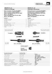
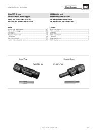
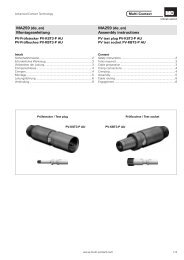
MA207-def-A<br />
Montageanleitung<br />
PV-Kupplungsbuchse PV-KBT3...<br />
PV-Kupplungsstecker PV-KST3...<br />
Bei der Benützung von anderen als von<br />
®<br />
MC angegebenen Einzelteilen und Werkzeugen,<br />
sowie bei Abweichung der hier beschriebenen<br />
Vorgänge zur Vorbereitung und<br />
Montage, kann bei der Selbstkonfektionierung<br />
weder die Sicherheit, noch die Einhaltung der<br />
technischen Daten gewährleistet werden.<br />
Zum Schutz vor einem elektrischen<br />
Schlag müssen bei der Selbstkonfektionierung<br />
der PV-Steckverbinder, diese immer allseitig<br />
von der Stromversorgung getrennt sein.<br />
Der Schutz vor einem elektrischen Schlag<br />
muss durch das Endprodukt gegeben sein.<br />
Gesteckte PV-Steckverbindungen dürfen<br />
nicht unter Last getrennt werden. Das Stecken<br />
und Trennen unter Spannung ist möglich.<br />
Nicht gesteckte Steckverbinder sind mit<br />
einer Verschlusskappe vor Feuchtigkeit und<br />
Schmutz zu schützen.<br />
Gesteckte Teile sind wasserdicht IP67.<br />
Sie sind aber nicht geeignet für einen<br />
dauerhaften Gebrauch unter Wasser. MC-PV-<br />
Steckverbinder nicht auf die Dachhaut<br />
aufliegen.<br />
Technische Daten und vorkonfektionierte<br />
Bauteile siehe MC® -Katalog 1 Solar line.<br />
E-Mail: basel@multi-contact.com<br />
MA207-def-A<br />
<strong>Assembly</strong> instructions<br />
PV-Female cable coupler PV-KBT3...<br />
PV-Male cable coupler PV-KST3...<br />
If, during self assembly, parts and tools<br />
other than those stated by MC are used or if<br />
the preparation and assembly instructions<br />
described here are disregarded then neither<br />
safety nor compliance with the technical data<br />
can be guaranteed.<br />
For protection against electric shock, PVconnectors<br />
must be isolated from the power<br />
supply while being assembled or disassembled.<br />
The end product must provide protection<br />
from electric shock.<br />
PV plug connections may not be<br />
disconnected while under load. Plugging and<br />
disconnecting while under voltage is<br />
permitted.<br />
Disconnected connectors should be<br />
protected from dirt and water with sealing<br />
caps.<br />
Plugged parts are watertight IP67. They<br />
can not be used permanently under water. Do<br />
not lay the MC-PV-Connectors on the roof<br />
surface.<br />
®<br />
See the MC -Catalogue 1 Solarline<br />
for<br />
technical data and assembled parts.<br />
Internet: www.multi-contact.com<br />
MA207-def-A<br />
<strong>Instructions</strong> de montage<br />
Raccord femelle PV PV-KBT3...<br />
Raccord mâle PV PV-KST3...<br />
STÄUBLI GROUP<br />
Lors d'une confection personnelle, si des<br />
composants et des outils différents de ceux prescrits<br />
par MC sont utilisés, si en outre les instruc-<br />
®<br />
tions de montage ci-après ne sont pas strictement<br />
appliquées, le respect des règles élémentaires<br />
de sécurité, des caractéristiques techniques<br />
indiquées, ne saurait être garanti.<br />
En vue de garantir une protection contre les<br />
chocs électriques, il est indispensable de réaliser<br />
les opérations de montage et de démontage<br />
hors tension, en veillant à déconnecter les différents<br />
composants de toute alimentation électrique.<br />
La protection contre les chocs électriques<br />
doit être garantie par le produit fini (monté).<br />
Les connecteurs PV ne doivent pas être débrochés<br />
sous charge. L’embrochage / débrochage<br />
sous tension reste possible.<br />
Les connecteurs doivent être protégés contre<br />
les infiltrations de poussière et les projections<br />
d’eau, avec des bouchons de protection.<br />
Les parties connectées sont étanches IP67,<br />
mais ne sont pas prévues pour l’utilisation permanente<br />
sous l’eau. Les connecteurs PV ne doivent<br />
pas reposer sur le toit.<br />
Caractéristiques techniques et pièces constituantes:<br />
consulter le catalogue MC<br />
®<br />
1 Solarline.<br />
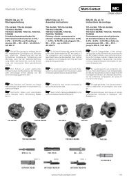
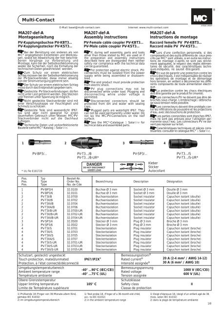
1<br />
2 3 4<br />
PV-BP3/...<br />
PV-T3.../B<br />
PV-T3.../B-UR*<br />
PV-SP3/...<br />
PV-T3.../S<br />
PV-T3.../S-UR*<br />
* UL file E181720<br />
Kleber<br />
Sticker<br />
Autocollant<br />
Pos. Typ Bestell-Nr.<br />
Pos. Type Order No. Bezeichnung Description Désignation<br />
Pos. Type No. de Cde<br />
1 PV-BP3/4 32.0100 Buchse Ø 3 mm Socket Ø 3 mm Douille Ø 3 mm<br />
1 PV-BP3/6 32.0101 Buchse Ø 3 mm Socket Ø 3 mm Douille Ø 3 mm<br />
2 PV-T3I/B 32.0700 Buchsenisolation Socket insulator Capuchon isolant (douille)<br />
2 PV-T3II/B 32.0702<br />
Buchsenisolation Socket insulator Capuchon isolant (douille)<br />
2 PV-T3III/B 32.0704<br />
Buchsenisolation Socket insulator Capuchon isolant (douille)<br />
2 PV-T3IIA/B 32.0706 Buchsenisolation Socket insulator Capuchon isolant (douille)<br />
2 PV-T3I/B-UR 32.0700-UR Buchsenisolation Socket insulator Capuchon isolant (douille)<br />
2 PV-T3II/B-UR 32.0702-UR Buchsenisolation Socket insulator Capuchon isolant (douille)<br />
2 PV-T3III/B-UR 32.0704-UR Buchsenisolation Socket insulator Capuchon isolant (douille)<br />
3 PV-SP3/4 32.0500 Stecker Ø 3 mm Plug Ø 3 mm Broche Ø 3 mm<br />
3 PV-SP3/6 32.0502<br />
Stecker Ø 3 mm Plug Ø 3 mm Broche Ø 3 mm<br />
4 PV-T3I/S 32.0701 Steckerisolation Plug insulator Capuchon isolant (broche)<br />
4 PV-T3II/S 32.0703<br />
Steckerisolation Plug insulator Capuchon isolant (broche)<br />
4 PV-T3III/S 32.0705<br />
Steckerisolation Plug insulator Capuchon isolant (broche)<br />
4 PV-T3IIA/S 32.0707 Steckerisolation Plug insulator Capuchon isolant (broche)<br />
4 PV-T3I/S-UR 32.0701-UR Steckerisolation Plug insulator Capuchon isolant (broche)<br />
4 PV-T3II/S-UR 32.0703-UR Steckerisolation Plug insulator Capuchon isolant (broche)<br />
4 PV-T3III/S-UR 32.0705-UR Steckerisolation Plug insulator Capuchon isolant (broche)<br />
Schutzart, gesteckt/ ungesteckt<br />
Touch protection, mated/unmated<br />
Protection, à l’état connecté/déconnecté<br />
Umgebungstemperaturbereich<br />
Ambient temperature range<br />
Température ambiante<br />
Obere Grenzstemperatur<br />
Upper limiting temperature<br />
Limite de Température supérieure<br />
2)<br />
Bemessungsstrom<br />
IP67/IP2X 1)<br />
2)<br />
Rated current<br />
2)<br />
Intensité assignée<br />
Bemessungspannung<br />
-40° ...90°C (IEC/CEI)<br />
Rated voltage<br />
-40° ...75°C (UL)<br />
Tension assignée<br />
Schutzklasse<br />
105° C Safety class<br />
II<br />
Classe de protection<br />
20 A (2-4 mm² / AWG 14-12)<br />
30 A (6 mm² / AWG 10)<br />
1000 V (IEC/CEI)<br />
600 V (UL)<br />
1) Prüfsonde 18 (Finger von 36 Monate altem Kind,<br />
gemäss IEC 61032)<br />
2) im Umgebungstemperaturbereich<br />
1) Test probe 18, (Finger of a 36-month-old child,<br />
acc. to IEC 61032)<br />
2) in the ambient temperature range<br />
1) Doigt d’épreuve 18, (doigt d’un enfant agé de 36<br />
mois, selon IEC 61032)<br />
2) dans la plage de température ambiante<br />
1/8
®<br />
<strong>Multi</strong>-<strong>Contact</strong><br />
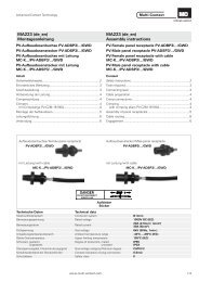
Notwendiges Werkzeug Tools required<br />
Outillage nécessaire<br />
(ill.1)<br />
Crimpzange<br />
PV-CZM-16100A für<br />
Leitungsquerschnitt von<br />
2,5 mm2-6mm2<br />
Bestell-Nr. :<br />
32.6020-16100A<br />
(ill.1)<br />
Crimping pliers<br />
PV-CZM-16100A for cable<br />
cross section of<br />
2,5 mm2- 6 mm2<br />
Order No. :<br />
32.6020-16100A<br />
(ill.1)<br />
Pince à sertir<br />
PV-CZM-16100A pour câble<br />
de section<br />
2,5 mm2- 6 mm2<br />
No. de Cde :<br />
32.6020-16100A<br />
ill.1<br />
Hinweise zur Bedienung<br />
der Crimpzange, siehe<br />
MA251-def (www.multicontact.com)<br />
Notes to the operation of<br />
the crimping pliers, see<br />
MA251-def (www.multicontact.com)<br />
Notice d’utilisation de la<br />
pinces à sertir, voir<br />
MA251-def (www.multicontact.com)<br />
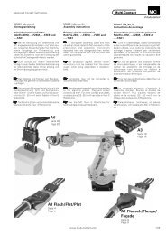
Lokator<br />
Locator<br />
Localisateur<br />
Selektor<br />
Selector<br />
Sélecteur<br />
PV-CZL<br />
(ill.2)<br />
Crimpzange PV-CZL für<br />
Leitungsquerschnitt von<br />
2mm2-6mm2<br />
Bestell-Nr. 32.6001<br />
oder<br />
Crimpzange PV-CZ für<br />
Leitungsquerschnitt von<br />
2,5 mm2 und 4 mm2<br />
Bestell-Nr. 32.6008<br />
(ill.2)<br />
Crimping pliers PV-CZL<br />
for cable cross section of<br />
2mm2-6mm2<br />
Order No. 32.6001<br />
or<br />
Crimping pliers PV-CZ for<br />
cable cross section of<br />
2,5 mm2and 4 mm2<br />
Order No. 32.6008<br />
(ill.2)<br />
Pince à sertir PV-CZL<br />
pour câble de section<br />
2mm2-6mm2<br />
No. de Cde 32.6001<br />
ou<br />
Pince à sertir PV-CZ<br />
pour câble de section<br />
2,5 mm2 et 4 mm2<br />
No. de Cde 32.6008<br />
ill.2<br />
PV-CZ<br />
1<br />
2<br />
Rückstellhebel<br />
Reset lever<br />
Levier anti retour<br />
Betätigungshebel<br />
Operating lever<br />
Levier de manoeuvre<br />
Zugstange<br />
Pull rod<br />
Tige de traction<br />
4<br />
3<br />
Konus<br />
Tapered spindle<br />
Cône<br />
Pos. Typ Bestell-Nr.<br />
Pos. Type Order No. Bezeichnung Description Désignation<br />
Pos. Type No. de Cde<br />
1 PV-RWZ3 32.6030 Montagegerät <strong>Assembly</strong> device Outil de montage<br />
inklusive 2 Konen incl. 2 tapered spindles avec 2 cônes inclus<br />
Einzelteile Individual parts Pièces détachées<br />
2 PV-R-RWZ3 32.6031 Montagegerät <strong>Assembly</strong> device Outil de montage<br />
3 PV-KO3 I+II 32.6032 Konus für Isolationen Gr. I+II Tapered spindle for insulators size I+II Cône pour isolants de tailles I+II<br />
4 PV-KO3 III 32.6033 Konus für Isolationen Gr. III Tapered spindle for insulators size III Cône pour isolants de tailles III<br />
Anschlussleitung<br />
Zur Sicherstellung einer ausreichenden<br />
Dichtheit des Leitungausgangs der PV-<br />
Steckverbinder sind die Anschlussleitung<br />
in den Isolationsgehäusen zugewiesenen<br />
Durchmesserbereichen einzusetzen.<br />
Weiterhin empfehlen wir bei der Auswahl<br />
von doppelt isolierten Anschlussleitungen<br />
darauf zu achten, dass ein ausreichender<br />
Haftsitz zwischen den Isolationsschichten<br />
gewährleistet ist, der ein Verschieben der<br />
beiden gegeneinander und dieser auf dem<br />
Leiter ausschliesst.<br />
Connecting cable<br />
To ensure that the cable outlet of the PV<br />
plug connectors is sufficiently watertight,<br />
the diameter of the connecting cables<br />
must be within the ranges specified for<br />
the insulating casings.<br />
Further, we also recommend that when<br />
selecting a double insulated connecting<br />
cable that there is sufficient adhesion between<br />
the insulating layers and the conductor,<br />
to prevent sliding.<br />
Câbles de raccordement<br />
Pour assurer une étanchéité suffisante de<br />
la sortie de câble du connecteur PV, utiliser<br />
des câbles de raccordement avec un diamètre<br />
sur isolant correspondant aux spécifications<br />
du capuchon isolant.<br />
Nous recommandons en outre, pour des<br />
câbles de raccordement à double isolation,<br />
de s'assurer qu'il existe entre les couches<br />
isolantes une adhé-rence suffisante pour<br />
empêcher un déplacement des couches<br />
l'une par rapport à l'autre ou par rapport au<br />
conducteur.<br />
2/8<br />
www.multi-contact.com
®<br />
<strong>Multi</strong>-<strong>Contact</strong><br />
G<br />
ill.3<br />
H<br />
Vorbereitung der<br />
Leitung<br />
(ill.3)<br />
Anschlussleitung mit einem<br />
Litzenaufbau Klasse<br />
2, 5 und 6 können angeschlossen<br />
werden. Verzinnte<br />
Leiter sind vorteilhaft.<br />
Durchmesser kontrollieren.<br />
G = Leitungsdurchgang<br />
H = Leitungs-Ø über Isolation<br />
Cable preparation<br />
(ill.3)<br />
Cables with class 2, 5 or 6<br />
construction can be connected.<br />
It is advantageous<br />
to use tinned conductors.<br />
Check diameter<br />
G= I.D. insulator<br />
H= O.D. over cable<br />
insulation<br />
Préparation du câble<br />
(ill.3)<br />
Les câbles de raccordement<br />
de classe de souplesse<br />
2, 5 et 6 peuvent<br />
être connectés. Les conducteurs<br />
étamés offrent<br />
des avantages.<br />
Contrôler les diamètres<br />
G=Ødepassage du câble<br />
H=Øducâble sur isolant<br />
PV-AZM<br />
L<br />
Grösse/Size/Grandeur G (mm) H (mm)<br />
I 2,8 3,2 - 4,8<br />
II 4,0 4,9 - 7,1<br />
III 6,0 6,5 - 7,6<br />
(ill.4)<br />
Leitung abisolieren.<br />
(ill.4)<br />
Strip cable insulation.<br />
(ill.4)<br />
Dénuder le câble.<br />
Typ<br />
Type<br />
Type<br />
Länge L (mm)<br />
Length L (mm)<br />
Longueur L (mm)<br />
PV-BP3/4 6 - 7.5<br />
PV-SP3/4 6 - 7.5<br />
PV-BP3/6 8.5 - 9.5<br />
PV-SP3/6 8.5 - 9.5<br />
ill.4<br />
Darauf achten, dass keine<br />
Einzeldrähte abgeschnitten<br />
werden.<br />
Empfohlenes Werkzeug:<br />
Abisolierzange PV-AZM,<br />
Bestell-Nr. 32.6027.<br />
(ill.5)<br />
Crimpanschlüsse<br />
Take care not to cut individual<br />
strands.<br />
Recommended tool:<br />
Stripping pliers PV-AZM,<br />
Order No. 32.6027.<br />
(ill.5)<br />
Crimp connections<br />
Veillez à ne pas couper les<br />
brins.<br />
Outil recommandé:<br />
Pince à dénuder PV-AZM,<br />
No. de Cde. 32.6027.<br />
(ill.5)<br />
Raccords à sertir<br />
For the connection of the<br />
conductors to the crimping<br />
sleeves of the PV<br />
plug connectors, we recommend<br />
using the stated<br />
crimping tools. The<br />
crimping sleeves are designed<br />
for flexible conductors<br />
(class 5 and 6) of<br />
the stated cross-sections.<br />
<strong>Multi</strong>-stranded conductors<br />
in AWG sizes may also<br />
be used. It is advantageous<br />
to use tinned wires.<br />
Für den Leiteranschluss<br />
an die Crimphülsen der<br />
PV-Steckverbinder empfehlen<br />
wir die angegebenen<br />
Crimpwerkzeuge einzusetzen.<br />
Die Crimphülsen<br />
sind für flexible Leiter<br />
(Klasse 5 und 6) der genannten<br />
Querschnitte ausgelegt.<br />
Der Einsatz mehrdrähtiger<br />
Leiter in AWG<br />
Abmessungen ist möglich.<br />
Verzinnte Leiter sind<br />
vorteilhaft.<br />
Pour le raccordement des<br />
conducteurs dans les fûts<br />
à sertir des connecteurs<br />
PV, nous recommandons<br />
l'emploi des outils de sertissage<br />
spécifiés. Les fûts<br />
à sertir sont conçus pour<br />
des conducteurs souples<br />
(classe 5 et 6) des sections<br />
mentionnées. L'utilisation<br />
de conducteurs<br />
multibrins en dimensions<br />
AWG est possible. Les<br />
conducteurs étamés sont<br />
recommandés.<br />
Crimpen Crimping Sertissage<br />
Crimpzangen-Selektorposition<br />
bzw. Pressprofil<br />
gem. Tabelle Seite 3.<br />
Selector position or crimp<br />
profile according to table<br />
page 3.<br />
Position du sélecteur ou<br />
profil de sertissage selon<br />
le tableau page 3.<br />
ill.5<br />
SEL.<br />
No.<br />
5<br />
3<br />
4<br />
6<br />
7<br />
2<br />
8<br />
1<br />
Crimpen mit<br />
Crimpzange PV-CZL<br />
Buchse oder Stecker in<br />
den Locator einlegen. Leitung<br />
bis zum Anschlag in<br />
die Crimphülse einstecken<br />
und crimpen.<br />
Crimping with crimping<br />
pliers PV-CZL<br />
Insert socket or pin into<br />
the locator. Insert cable into<br />
crimp sleeve up to stop<br />
and crimp.<br />
Sertir avec la pince à<br />
sertir PV-CZL<br />
Introduire la douille ou la<br />
broche dans le sélecteur.<br />
Introduire le câble dans le-<br />
fût à sertir jusqu’en butée<br />
et sertir.<br />
ill.6<br />
www.multi-contact.com 3/8
®<br />
Crimpen mit Crimp-<br />
ill.7<br />
Q max. 1 mm<br />
zange PV-CZ<br />
Buchse oder Stecker in<br />
den Locator legen und<br />
durch leichtes betätigen<br />
der Crimpzange klemmen.<br />
Leitung bis zum Anschlag<br />
in die Crimphülse<br />
einstecken und crimpen.<br />
Crimpzangen<br />
Crimp tools<br />
Pinces à sertir<br />
Bestell-Nr.<br />
Order No.<br />
No. de Cde<br />
PV-CZL 32.6001 Selectorposition<br />
Selector position<br />
Position du sélecteur<br />
Crimpprofil<br />
PV-CZ 32.6008 Crimp profile<br />
Profil de sertissage<br />
1) ohne Locator verpressen<br />
2) nur für flexible Leiter<br />
(Klasse 5 und 6 nach IEC<br />
60228, DIN VDE 0295)<br />
Crimping with crimping<br />
pliers PV-CZ<br />
Place the socket or pin in<br />
the locator and slowly actuate<br />
the crimping pliers<br />
to lightly grasp the socket<br />
or pin. Insert cable into the<br />
crimp sleeve up to stop<br />
and crimp.<br />
ill.6<br />
ill.7<br />
Sertir avec la pince à<br />
sertir PV-CZ<br />
Introduire la douille ou la<br />
broche dans le locator et<br />
serrer légèrement pour<br />
l'immobiliser. Introduire le<br />
câble dans le fût jusqu’en<br />
butée et sertir.<br />
Leitungquerschnitt<br />
Cable cross section<br />
Section du câble<br />
2mm2 2,5mm2 3,5mm2 4mm2 6mm2<br />
14 AWG 12 AWG 10 AWG<br />
3 4 4 4 5 5 61)<br />
- 2,52) - - 42)<br />
- -<br />
1) Crimp without locator<br />
2) Flexible cable only<br />
class 5 and 6 acc. to IEC<br />
60228, DIN VDE 0295.<br />
1) Sertir sans locator<br />
2) Uniquement pour câble<br />
souple (classe 5 et 6 d'après<br />
CEI 60228, DIN VDE 0295).<br />
ill.8<br />
4 mm 2 2.5 mm 2 (ill.8)<br />
<strong>Multi</strong>-<strong>Contact</strong><br />
Achtung:<br />
Crimpung kontrollieren.<br />
Alle Drähte der Litze müssen<br />
sauber in der Bohrung<br />
eingeführt und im<br />
Sichtloch sichtbar sein.<br />
Das Mass max. 1 mm<br />
darf nicht überschritten<br />
werden.<br />
(ill.8)<br />
Caution:<br />
Check crimping. All conductor<br />
wires should be<br />
cleanly inserted into thehole<br />
and the max. dimension<br />
of 1 mm should not<br />
be exceeded.<br />
(ill.8)<br />
Attention:<br />
Contrôler le sertissage.<br />
Tous les brins du câble doivent<br />
être introduits et la<br />
cote maximale de 1 mm<br />
doit être respectée.<br />
Montage <strong>Assembly</strong> Montage<br />
Industriealkohol<br />
Industrial alcohol<br />
alcool industriel<br />
(ill.9)<br />
Hinweis:<br />
Der Montagevorgang<br />
kann erleichtert werden,<br />
wenn der Leitungausgang<br />
der Steckverbinderisolation<br />
vor dem Einsetzen der<br />
Kontakte in Industriealkohol<br />
getaucht wird.<br />
(ill.9)<br />
Note:<br />
To facilitate assembly,<br />
the insulation of the plug<br />
connectors may be immersed<br />
in industrial alcohol<br />
before inserting the<br />
contacts.<br />
(ill.9)<br />
Remarque:<br />
L’emmanchement des<br />
contacts peut être facilité<br />
en plongeant au préalable<br />
les corps isolants dans de<br />
l’alcool industriel.<br />
ill.9<br />
R<br />
Z<br />
(ill.10)<br />
Montagegerät an der vorderen<br />
Stange festhalten,<br />
den Rückstellhebel R<br />
gleichzeitig öffnen und<br />
die Zugstange Z ganz zurückstossen.<br />
(ill.10)<br />
Hold the assembly device<br />
by the front barrel,<br />
at the same time opening<br />
the reset lever R<br />
and pushing back the pull<br />
rod Z to its starting position.<br />
(ill.10)<br />
Maintenir l'outil de montage<br />
par son canon tout<br />
en actionnant le levier anti<br />
retour R, puis pousser<br />
la tige de traction Z jusqu'à<br />
sa position de départ<br />
ill.10<br />
4/8<br />
www.multi-contact.com
®<br />
<strong>Multi</strong>-<strong>Contact</strong><br />
PV-KO3 I+II<br />
~4 mm min.<br />
Rillen / Grooves / Rainures<br />
(ill.11)<br />
Konus auswählen:<br />
PV-KO3 I+II für Buchsenund<br />
Steckerisolationen<br />
der Grösse I + II,<br />
PV-KOIII für Buchsenund<br />
Steckerisolationen<br />
der Grösse III.<br />
Konus von hinten durch<br />
die Buchsen- bzw. Steckerisolation<br />
stossen bis<br />
der Zugstift ca. 4 cm aus<br />
der Buchsen- bzw. Steckerisolation<br />
ragt.<br />
(ill.11)<br />
Select the tapered<br />
spindle:<br />
PV-KO3 I+II for socketand<br />
pin-insulation size<br />
I+II, PV-KO3 III for<br />
socket- and pin-insulation<br />
size III.<br />
Push tapered spindle<br />
through insulator until<br />
the pull rod protrudes<br />
approx. 4 cm out of the<br />
insulator.<br />
(ill.11)<br />
Choisir le cône:<br />
PV-KO3 I+II pour capuchons<br />
isolants des douilles<br />
et broches de tailles<br />
I+II, PV-KO3 III pour capuchons<br />
isolants des<br />
douilles et broches de taille<br />
III.<br />
Pousser le cône par<br />
l’arrière du capuchon isolant<br />
jusqu’à ce que la broche<br />
de traction dépasse<br />
de 4 cm.<br />
PV-KO3 III<br />
ill.11<br />
ill.12<br />
~4 mm min.<br />
(ill.12)<br />
Buchse oder Stecker mit<br />
angecrimpter Leitung bis<br />
zum Anschlag in den Konus<br />
einführen. Konus von<br />
vorne in das Montagegerät<br />
einführen und dabei<br />
die Zugstange festhalten.<br />
Achtung:<br />
Wenn der Betätigungshebel<br />
bei der ersten Bewegung<br />
klemmt, ist der Konus<br />
nicht bis zum Anschlag<br />
eingesteckt. Keine<br />
Kraft anwenden! Das<br />
Werkzeug könnte beschädigt<br />
werden.<br />
Die Zugstange nochmals<br />
zurückstossen und den<br />
Konus bis zum Anschlag<br />
einstecken.<br />
(ill.12)<br />
Insert socket or pin with<br />
crimped cable into the tapered<br />
spindle up to the<br />
stop. Insert tapered<br />
spindle into the assembly<br />
device and at the same<br />
time hold the pull rod in<br />
position.<br />
Attention:<br />
If the pull rod jams after<br />
the first movement, the<br />
tapered spindle is not correctly<br />
inserted.<br />
Do not use force !<br />
The assembly device<br />
could be damaged.<br />
Push back the pull rod<br />
again and insert the tapered<br />
spindle up to the<br />
stop.<br />
(ill.12)<br />
Introduire la douille ou la<br />
broche (avec le câble serti)<br />
jusqu'au fond du cône<br />
tout en maintenant la tige<br />
de traction dans sa position.<br />
Attention: Si on constate<br />
que lors de la première<br />
manœuvre le levier se bloque<br />
on risque d’endommager<br />
le pistolet si on force<br />
sur celui ci.<br />
Cela veut dire que le cône<br />
n’est pas bien positionné<br />
dans la pince, il faut<br />
dans ce cas repousser la<br />
tige de traction à sa position<br />
de départ et enfoncer<br />
le cône jusqu’en butée.<br />
(ill.13)<br />
Durch mehrmaliges Zusammendrücken<br />
des Betätigungshebels<br />
den Konus<br />
durch den Gegenhalter<br />
ziehen und so lange<br />
die Leitung am Anschlag<br />
halten, bis die Buchsenbzw.<br />
Steckerisolation das<br />
Kabel erfasst und ganz<br />
eingezogen hat.<br />
(ill.13)<br />
Hold the cable in position<br />
and press the lever several<br />
times to draw the<br />
spindle through the socket<br />
or pin insulator seated<br />
in the counter piece,<br />
until the insulator has grasped<br />
the cable and pulled<br />
it in completely.<br />
(ill.13)<br />
Actionner plusieurs fois<br />
le levier de manoeuvre<br />
en maintenant le câble<br />
en butée dans le fond du<br />
cône jusqu'à ce que le câble<br />
fasse prise avec le capuchon<br />
isolant. Continuer<br />
à actionner le levier de<br />
manoeuvre jusqu'à la sortie<br />
du cône de l'isolant.<br />
ill.13<br />
K<br />
ill.14<br />
Z<br />
(ill.14)<br />
Buchse bzw. Stecker herausnehmen<br />
(ill.14)<br />
Take the socket or pin out<br />
(ill.14)<br />
Enlever la douille ou la broche<br />
ill.15<br />
(ill.15)<br />
Durch Zurückstellen der<br />
Zugstange Z kann der Konus<br />
K herausgenommen<br />
werden.<br />
(ill.15)<br />
To take out the tapered<br />
spindle K push the pull<br />
rod Z back to its starting<br />
position.<br />
(ill.15)<br />
Pour retirer le cône K de<br />
l'outil repousser la tige<br />
de traction Z à sa position<br />
de départ.<br />
www.multi-contact.com<br />
5/8
®<br />
(ill.16)<br />
Durch leichtes Ziehen an<br />
der Leitung sicherstellen,<br />
dass die Tülle auf dem Metallteil<br />
richtig eingerastet<br />
ist.<br />
Bei richtiger Einbaulage<br />
müssen die eingebauten<br />
Teile mit der Isolations-<br />
Stirnseite fluchten.<br />
(ill.16)<br />
Make sure the insulator<br />
is properly engaged on<br />
the metal part. If the<br />
parts have been assembled<br />
correctly, they will<br />
be flush with the end of<br />
the insulator.<br />
<strong>Multi</strong>-<strong>Contact</strong><br />
(ill.16)<br />
S’assurer que l’isolant est<br />
correctement monté sur<br />
la pièce métallique en tirant<br />
légèrement le câble.<br />
Les pièces métalliques<br />
doivent être à fleur de la face<br />
avant de l’isolant.<br />
ill.16<br />
(ill.17)<br />
Beiliegender Kleber<br />
“ Danger Do not disconnect<br />
under load” in der<br />
Nähe des PV-<br />
Kupplungssteckers anbringen.<br />
(ill.17)<br />
(ill.17)<br />
Attach enclosed sticker Coller l’étiquette<br />
“ Danger Do not disconnect<br />
under load” as nect under load” à pro-<br />
“ Danger Do not discon-<br />
near as possible to the ximité du raccord mâle<br />
male cable coupler. PV.<br />
ill.17<br />
Cable routing*:<br />
SHARP RADIUS<br />
INCORRECT Routing of cable<br />
CORRECT Routing of cable<br />
* Beachten Sie die Spezifikationen des Leitungsherstellers betreffend Biegeradius<br />
* Refer to cable manufactures specification for minimum bending radius.<br />
* Se référer aux spécifications du fabricant de câbles pour un rayon de courbure minimal<br />
GAP<br />
Incorrect Engagement<br />
Correct Engagement<br />
6/8<br />
www.multi-contact.com
®<br />
<strong>Multi</strong>-<strong>Contact</strong><br />
Funktionsstörungen des<br />
Montagegerätes<br />
und Massnahmen zur Behebung<br />
Achtung: Sollte das Montagegerät bei der<br />
Anwendung blockieren, darf keine Kraft<br />
angewendet werden. Das Montagegerät<br />
könnte beschädigt werden.<br />
Malfunctions of the assembly device<br />
and corrective measures<br />
Important: If the assembly device jams in<br />
use, do not apply force since this could<br />
damage the device.<br />
Incidents de fonctionnement de<br />
l’appareil de montage et mesures<br />
pour y remédier<br />
Attention: Si l’appareil de montage se<br />
bloque lors de l’utilisation, ne pas<br />
employer la force. Cela risquerait<br />
d’endommager l’appareil de montage.<br />
Störung Grund Beheben Bemerkung<br />
Problem Cause Corrective measure Remark<br />
Incident Raison Remède Remarque<br />
Betätigungshebel klemmt Tülle nicht weit genug a. Rückstellhebel betätigen Betätigungshebel beim Zurückbei<br />
der ersten Bewegung auf Konus geschoben b. Zugstange bis an Anschlag schieben der Zugstange nicht<br />
(min. 4cm) demzufolge zurück schieben bewegen.<br />
ist der Konus nicht tief c. Tülle min. 4cm auf den<br />
genug in die Klemmzange<br />
geschoben<br />
Konus schieben<br />
d. Konus bis zum Anschlag in<br />
das Montagegerät schieben<br />
e. Montagevorgang kann<br />
durchgeführt werden<br />
Operating lever jams on Bush not pushed far enough a. Operate reset lever Do not move the operating<br />
first movement onto tapered pin (min. 4cm). b. Push puller rod back to the lever when pushing back the<br />
As a result, the tapered pin is stop puller rod<br />
not pushed far enough into<br />
the clamp<br />
c. Push the bush at least 4cm<br />
onto the tapered pin<br />
d. Push the tapered pin into the<br />
assembly device as far as it<br />
will go<br />
e. <strong>Assembly</strong> can be carried out<br />
Le levier de manoeuvre se Manchon pas poussé assez a. Actionner le levier anti retour Ne pas déplacer le levier de<br />
bloque au premier mouvement loin sur le cône (min. 4cm). b. Ramener la tige de traction manoeuvre en ramenant la tige<br />
Par conséquent, le cône n’est en arrière jusqu’en butée de traction en arrière<br />
pas poussé assez profondément<br />
dans la pince.<br />
c. Pousser le manchon d’au<br />
moins 4cm sur le cône<br />
d. Pousser le cône dans<br />
l’appareil de montage jusqu’en<br />
butée<br />
e. L’opération de montage<br />
peut être effectuée<br />
Betätigungshebel klemmt Zugstange zu weit a. Rückstellhebel betätigen Betätigungshebel beim Zurück-<br />
Zugstange klemmt zurückgezogen b. Zugstange zurückschieben schieben der Zugstange nicht<br />
bewegen<br />
Operating lever jams, Puller rod pulled back too far a. Operate reset lever Do not move the operating<br />
puller rod jams b. Push back puller rod lever when pushing back the<br />
puller rod<br />
Le levier de manoeuvre se Tige de traction ramenée trop a. Actionner le levier anti retour Ne pas déplacer le levier de<br />
bloque loin en arrière b. Ramener la tige de traction manoeuvre en ramenant la<br />
La tige de traction se bloque en arrière tige de traction en arrière<br />
Grosser Kraftaufwand Tülle trocken a. Tülle vor dem Aufschieben<br />
notwendig<br />
auf den Konus in Industriealkohol<br />
tauchen<br />
Strong force needed in order Bush dry a. Immerse bush in industrial<br />
to operate<br />
alcohol before pushing onto<br />
tapered pin<br />
Il est nécessaire d’exercer Manchon sec a. Tremper le manchon dans<br />
une force importante<br />
l’alcool industriel avant de le<br />
monter sur le cône<br />
www.multi-contact.com<br />
7/8
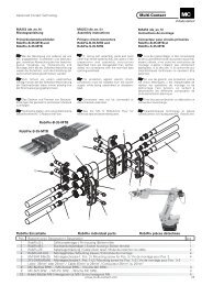
®<br />
<strong>Multi</strong>-<strong>Contact</strong><br />
PV-RWZ3<br />
32.6030<br />
Zugstange<br />
Pull rod<br />
Tige de traction<br />
Rückstellhebel<br />
Reset lever<br />
Levier anti retour<br />
Betätigungshebel<br />
Operating lever<br />
Levier de manoeuvre<br />
8/8<br />
MA207-def-A<br />
Änderungen vorbehalten/Subject to alterations/Modifications sous réserve.<br />
02/07 Index e Copyright by <strong>Multi</strong>-<strong>Contact</strong> AG, Switzerland MC-Solarline-Doc 2000-02/07<br />
www.multi-contact.com