Assembly instructions MA260 (it_en) - Multi-Contact
Assembly instructions MA260 (it_en) - Multi-Contact
Assembly instructions MA260 (it_en) - Multi-Contact

Create successful ePaper yourself
Turn your PDF publications into a flip-book with our unique Google optimized e-Paper software.
Advanced <strong>Contact</strong> Technology<br />
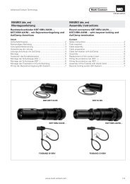
MA000 <strong>MA260</strong> (de_<strong>en</strong>) (<strong>it</strong>_<strong>en</strong>)<br />
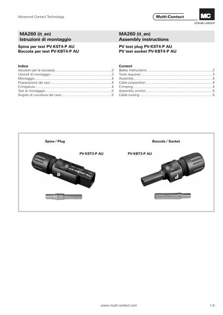
Montageanle<strong>it</strong>ung<br />
Istruzioni di montaggio<br />
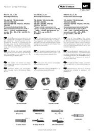
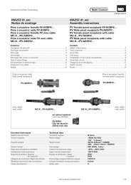
Spina per test PV-KST4-P AU<br />
Boccola per test PV-KBT4-P AU<br />
Indice<br />
Istruzioni per la sicurezza ............................................................2<br />
Ut<strong>en</strong>sili di montaggio ................................................................3<br />
Montaggio .................................................................................4<br />
Preparazione dei cavi .................................................................4<br />
Crimpatura .................................................................................4<br />
Test di montaggio ......................................................................5<br />
Angolo di curvatura del cavo .....................................................5<br />
Spina / Plug<br />
MA000 <strong>MA260</strong> (de_<strong>en</strong>) (<strong>it</strong>_<strong>en</strong>)<br />
<strong>Assembly</strong> <strong>instructions</strong><br />
PV test plug PV-KST4-P AU<br />
PV test socket PV-KBT4-P AU<br />
PV-KST3-P AU PV-KBT3-P AU<br />
Cont<strong>en</strong>t<br />
Safety Instructions ......................................................................2<br />
Tools required ............................................................................3<br />
<strong>Assembly</strong> ...................................................................................4<br />
Cable preparation ......................................................................4<br />
Crimping ....................................................................................4<br />
<strong>Assembly</strong> control .......................................................................5<br />
Cable routing .............................................................................5<br />
Boccola / Socket<br />
www.multi-contact.com 1 / 8
Advanced <strong>Contact</strong> Technology<br />
Istruzioni di montaggio Safety Instructions<br />
I prodotti possono essere montati e installati solo da esperti<br />
qualifi cati e formati, rispettando tutte le disposizioni di sicurezza<br />
e le norme di legge applicabili.<br />
<strong>Multi</strong>-<strong>Contact</strong> (MC) declina qualsiasi responsabil<strong>it</strong>à derivante<br />
dal mancato rispetto delle pres<strong>en</strong>ti avvert<strong>en</strong>ze.<br />
Utilizzare esclusivam<strong>en</strong>te i pezzi e gli attrezzi indicati da MC.<br />
Rispettare sempre le procedure qui descr<strong>it</strong>te per la preparazione<br />
e il montaggio, poiché in caso contrario non potranno essere<br />
garant<strong>it</strong>i né la sicurezza né il rispetto delle caratteristiche<br />
tecniche indicate. Non apportare in nessun modo modifi che<br />
al prodotto.<br />
I connettori non di fabbricazione MC, che possono essere collegati<br />
con elem<strong>en</strong>ti MC e che a volte sono indicati dal produttore<br />
come “compatibili con MC“, non soddisfano i requis<strong>it</strong>i<br />
per un collegam<strong>en</strong>to elettrico sicuro e stabile nel tempo e, per<br />
motivi di sicurezza, non possono essere collegati con elem<strong>en</strong>ti<br />
MC. MC declina quindi qualsiasi responsabil<strong>it</strong>à nel caso in cui<br />
questi connettori non autorizzati da MC v<strong>en</strong>gano collegati con<br />
elem<strong>en</strong>ti MC e causino quindi dei danni.<br />
I lavori qui descr<strong>it</strong>ti non possono essere esegu<strong>it</strong>i su<br />
pezzi sotto t<strong>en</strong>sione o corr<strong>en</strong>te.<br />
La protezione da scosse elettriche deve essere garant<strong>it</strong>a<br />
nel prodotto fi nale e accertata dall’ut<strong>en</strong>te.<br />
I connettori non possono essere staccati sotto carico.<br />
È cons<strong>en</strong>t<strong>it</strong>o collegare e staccare i connettori<br />
sotto t<strong>en</strong>sione.<br />
I connettori sono impermeabili in conform<strong>it</strong>à con la<br />
classe di protezione IP, ma non sono idonei all’uso<br />
prolungato sott‘acqua. Non mettere il connettore a<br />
diretto contatto con la copertura del tetto.<br />
Proteggere i connettori non utilizzati da umid<strong>it</strong>à e<br />
sporco con una capsula di chiusura (MC4 codice<br />
32.0716 per prese e 32.0717 per spine). I connettori<br />
sporchi non possono essere collegati tra loro.<br />
Il connettore non può mai essere sottoposto a un<br />
carico di trazione meccanico costante. Il cavo dovrebbe<br />
essere fi ssato con una fascetta serracavo.<br />
MC consiglia di non utilizzare né cavi in PVC né cavi<br />
non stagnati del tipo H07RN-F.<br />
I connettori di controllo PV sono p<strong>en</strong>sati principalm<strong>en</strong>te<br />
per l’utilizzo in ambi<strong>en</strong>ti interni (laboratori di<br />
prova, capannoni di produzione).<br />
Ulteriori caratteristiche tecniche sono indicate nel<br />
catalogo del prodotto.<br />
2 / 8 www.multi-contact.com<br />
The products may be assembled and installed only by su<strong>it</strong>ably<br />
qualifi ed and trained specialists w<strong>it</strong>h due observance of all applicable<br />
safety regulations.<br />
<strong>Multi</strong>-<strong>Contact</strong> (MC) declines any liabil<strong>it</strong>y in the ev<strong>en</strong>t of failure<br />
to observe these warnings.<br />
Use only the compon<strong>en</strong>ts and tools specifi ed by MC. Do not<br />
deviate from the preparation and assembly procedures described<br />
here, since in this ev<strong>en</strong>t, in the ev<strong>en</strong>t of self-assembly, no<br />
guarantee can be giv<strong>en</strong> as to safety or conform<strong>it</strong>y w<strong>it</strong>h the<br />
technical data. Do not modify the product in any way.<br />
Connectors not made by MC which can be mated w<strong>it</strong>h MC<br />
elem<strong>en</strong>ts and in some cases are also described as ”MC-compatible”<br />
do not conform to the requirem<strong>en</strong>ts for safe electrical<br />
connection w<strong>it</strong>h long-term stabil<strong>it</strong>y, and for safety reasons<br />
must not be plugged together w<strong>it</strong>h MC elem<strong>en</strong>ts. MC can<br />
therefore accept no liabil<strong>it</strong>y for damage which occurs as a result<br />
of mating these connectors which lack MC approval w<strong>it</strong>h<br />
MC elem<strong>en</strong>ts.<br />
The work described here must not be carried out<br />
on live or load-carrying parts.<br />
Protection from electric shock must be assured by<br />
the <strong>en</strong>d product and <strong>it</strong>s user<br />
The plug connections must not be disconnected<br />
under load. Plugging and unplugging wh<strong>en</strong> live is<br />
perm<strong>it</strong>ted.<br />
The plug connectors are watertight in accordance<br />
w<strong>it</strong>h IP protection class. However, they are not<br />
su<strong>it</strong>able for continuous operation under water. Do<br />
not place the plug connectors directly on the roof<br />
membrane.<br />
Unmated plug connectors must be protected from<br />
moisture and dirt w<strong>it</strong>h a sealing cap (MC4 Article<br />
No. 32.0716 for sockets and 32.0717 for plugs). The<br />
male and female parts must not be plugged together<br />
wh<strong>en</strong> soiled.<br />
The plug connection must not be subjected to continuous<br />
mechanical t<strong>en</strong>sion. The cable should be fi xed<br />
w<strong>it</strong>h cable binders.<br />
MC does not recomm<strong>en</strong>d the use of e<strong>it</strong>her PVC<br />
cables or untinned cables of type H07RN-F.<br />
PV test plugs are int<strong>en</strong>ded primarily for indoor use<br />
(test laboratories, production halls).<br />
For further technical data please see the product<br />
catalogue.<br />
Spiegazione dei simboli Explanation of the symbols<br />
Pericolo! Voltaggi pericolosi<br />
Warning of dangerous voltages<br />
Pericolo! Area pericolosa Warning of a hazard area<br />
Consiglio utile Useful hint or tip
Advanced <strong>Contact</strong> Technology<br />
15<br />
CHROM - VANADIUM<br />
1<br />
2<br />
3<br />
4<br />
5<br />
6<br />
7<br />
8<br />
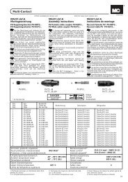
Attrezzo richiesto Tools required<br />
(ill. 1)<br />
Spela fi li PV-AZM... inclusa lama spela<br />
fi li inegrata e cacciav<strong>it</strong>e esagonale<br />
2,5 mm.<br />
Sezione del cavo:1,5 / 2,5 / 4 / 6 mm²<br />
Tipo: PV-AZM-1.5/6<br />
No. di codice: 32.6027-156<br />
(ill. 2)<br />
Pinza per crimpare PV-CZM... con<br />
posizionatore e inserto di crimpatura<br />
integrato.<br />
Sezione del cavo: 2,5 / 4 / 6mm²<br />
(14/12/10 AWG)<br />
Tipo: PV-CZM-16100<br />
No. di codice: 32.6020-16100A<br />
Inserti di crimpatura intercambiabili<br />
con brugola esagonale da 2,5mm<br />
Tipo: PV-ES-CZM-16100<br />
No. di codice: 32.6021-16100<br />
(ill. 3)<br />
Chiave fi ssa doppia PV-MS,<br />
1 N° di codice = 2 pezzi<br />
No. di codice: 32.6024<br />
(ill. 4)<br />
Inserto per stringere PV-WZ-AD/<br />
GWD<br />
No. di codice: 32.6006<br />
(ill. 5)<br />
Inserto per fi ssare PV-SSE-AD4<br />
No. di codice: 32.6026<br />
(ill. 6)<br />
Pin di test PV-PST<br />
No. di codice: 32.6028<br />
(ill. 7)<br />
Chiave fi ssa 15mm<br />
(ill. 8)<br />
Chiave dinamometrica 12mm<br />
(ill. 1)<br />
Stripping pliers PV-AZM... incl.<br />
built-in wire stripping blade as well as<br />
hexagonal screwdriver A/F 2,5.<br />
Conductor cross section:<br />
1,5 / 2,5 / 4 / 6 mm²<br />
Type: PV-AZM-1.5/6<br />
Order No.: 32.6027-156<br />
(ill. 2)<br />
Crimping tool MC3 PV-CZM... incl.<br />
locator and built-in crimping insert.<br />
Crimping range: 2,5 / 4 / 6mm²<br />
(14/12/10 AWG)<br />
Type: PV-CZM-16100<br />
Order No.: 32.6020-16100A<br />
Interchangeable crimping inserts incl.<br />
hexagonal screwdriver A/F 2,5.<br />
Type: PV-ES-CZM-16100<br />
Order No.: 32.6021-16100<br />
(ill. 3)<br />
Op<strong>en</strong>-<strong>en</strong>d spanner PV-MS<br />
1 Set = 2 pieces<br />
Order No.: 32.6024<br />
(ill. 4)<br />
PV-WZ-AD/GWD socket wr<strong>en</strong>ch<br />
insert to tight<strong>en</strong><br />
Order No.: 32.6006<br />
(ill. 5)<br />
PV-SSE-AD4 socket wr<strong>en</strong>ch insert to<br />
secure<br />
Order No.: 32.6026<br />
(ill. 6)<br />
Test plug PV-PST<br />
Order No.: 32.6028<br />
(ill. 7)<br />
Op<strong>en</strong>-<strong>en</strong>d spanner A/F 15mm<br />
(ill. 8)<br />
Torque screwdriver A/F 12mm<br />
www.multi-contact.com 3 / 8
Advanced <strong>Contact</strong> Technology<br />
L= 6 - 7,5mm<br />
S<br />
A<br />
A<br />
max. 1 mm<br />
4 / 8 www.multi-contact.com<br />
9<br />
10<br />
11<br />
12<br />
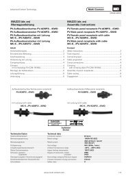
Montaggio <strong>Assembly</strong><br />
Preparazioni dei cavi Cable preparation<br />
Possono essere collegati cavi con<br />
costruzione di classe 5 o 6.<br />
Avvert<strong>en</strong>za:<br />
Non utilizzare conduttori non<br />
protetti o già ossidati. Si consiglia di<br />
utilizzare i conduttori stagnati. Tutti<br />
i cavi solari MC hanno conduttori<br />
stagnati di alta qual<strong>it</strong>à.<br />
(ill. 9)<br />
Possono essere connessi cavi con<br />
sezione conduttore compresa tra 2.5 –<br />
4mm² corrispond<strong>en</strong>te a 14 – 10 AWG.<br />
Att<strong>en</strong>zione<br />
I pin o le boccole di test devono<br />
corrispondere al relativo diametro<br />
del cavo (A).<br />
Tipo: A = Ø del pressacavo<br />
PV-K...T4/...6I: 3 – 6 mm<br />
PV-K...T4/...6II: 5.5 – 9 mm<br />
(ill. 10)<br />
Spellare il cavo.<br />
Rimuovere da 6,0 a 7,5 mm di isolam<strong>en</strong>to<br />
dalla parte terminale del cavo<br />
Att<strong>en</strong>zione:<br />
Prestare att<strong>en</strong>zione a non tagliare<br />
i trefoli.<br />
Avvert<strong>en</strong>za:<br />
Per indicazioni sull’uso della<br />
pinza per crimpare PV-AZM e sulla<br />
sost<strong>it</strong>uzione dei k<strong>it</strong> di lame, consultare<br />
le istruzioni d’uso di MA267 at www.<br />
multi-contact.com<br />
Crimpatura Crimping<br />
Importante<br />
Utilizzare esclusivam<strong>en</strong>to l‘inserto<br />
di crimpatura MC3 PV-ES-<br />
CZM-16100!<br />
(ill. 11)<br />
1. Inserire la parte metallica del connettore<br />
femmina o maschio nella<br />
guida per la sezione appropriata.<br />
2. Inserire il cavo nella bussola di<br />
crimpatura fi no in fondo e fi ssarlo.<br />
Mant<strong>en</strong>ere il cavo in posizione<br />
all’interno della bussola.<br />
(ill. 12)<br />
Att<strong>en</strong>zione:<br />
I trefoli devono essere visibili<br />
attraverso il foro S e la distanza<br />
massima di 1mm non deve essere<br />
superata esternam<strong>en</strong>te.<br />
3. Serrare completam<strong>en</strong>te la pinza per<br />
crimpare.<br />
Cables w<strong>it</strong>h a strand construction of<br />
classes 5 and 6 can be connected.<br />
Note:<br />
Use no uncoated or already<br />
oxidised conductors. It is advantage<br />
to use tinned conductors. All MC<br />
solar cables have high-qual<strong>it</strong>y, tinned<br />
conductors.<br />
(ill. 9)<br />
Cables w<strong>it</strong>h conductor cross section<br />
from 2,5 - 4mm² resp. from 14 - 10<br />
AWG can be connected.<br />
Att<strong>en</strong>tion<br />
Take care that the type of test<br />
plug or test socket matches the<br />
cable diameter (A).<br />
Type: A = Ø range of cable<br />
PV-K...T4/...6I: 3 – 6 mm<br />
PV-K...T4/...6II: 5.5 – 9 mm<br />
(ill. 10)<br />
Strip cable insulation 1)<br />
Remove 6 to 7,5 mm of insulation<br />
from the <strong>en</strong>d of the cable.<br />
Att<strong>en</strong>tion<br />
Take care not to cut individual<br />
strands.<br />
1) For directions on the operation of stripping<br />
pliers PV-AZM... and changing blade<br />
sets, see operating instruction MA267 at<br />
www.multi-contact.com<br />
Important<br />
Use only the MC3 crimp insert<br />
PV-ES-CZM-16100!<br />
(ill. 11)<br />
1. Place the metal part of the female<br />
or male coupler in the guide for the<br />
appropriate cross section.<br />
2. Insert the wire into the crimping<br />
sleeve as far as <strong>it</strong> will go. Hold the<br />
wire in place in the sleeve.<br />
(ill. 12)<br />
Att<strong>en</strong>tion<br />
All strands of the wires must be<br />
correctly inserted into the borehole<br />
and visible in sight hole S.<br />
The max. distance of 1mm must<br />
not be exceeded.<br />
3. Completely close the crimping tool.
Advanced <strong>Contact</strong> Technology<br />
marchio bianca<br />
13<br />
14<br />
15<br />
16<br />
17<br />
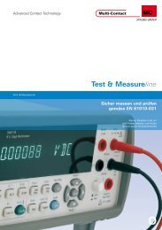
(ill. 13)<br />
4. Controllare visivam<strong>en</strong>te la crimpatura.<br />
Avvert<strong>en</strong>za:<br />
per le operazioni con la pinza per<br />
crimpare, vedere MA251<br />
www.multi-contact.com<br />
(ill. 13)<br />
4. Visually check the crimp.<br />
Note:<br />
to the operation of the crimping<br />
pliers, see MA251, www.multicontact.com<br />
Test di montaggio <strong>Assembly</strong> control<br />
(ill. 14)<br />
Inserire il contatto crimpato<br />
nell’isolam<strong>en</strong>to del connettore femmina<br />
o maschio fi nché non scatta<br />
in posizione. Tirando leggerm<strong>en</strong>te il<br />
cavo, assicurarsi che la parte metallica<br />
sia collegata in modo corretto.<br />
(ill. 15)<br />
Inserire il pin di test con il lato corrispond<strong>en</strong>te<br />
nella presa o nella spina fi no<br />
alla posizione di arresto. Se il contratto<br />
è montato correttam<strong>en</strong>te, il marchio<br />
bianco sul pin di test deve essere<br />
ancora visibile.<br />
(ill. 16)<br />
Avv<strong>it</strong>are il pressacavo con le chiavi<br />
PV-MS<br />
o<br />
(ill. 17)<br />
Avv<strong>it</strong>are il pressacavi con l‘ut<strong>en</strong>sile<br />
PV-WZ-AD/GWD e PV-SSE-AD4.<br />
Angolo di curvatura del cavo Cable routing<br />
Fare riferim<strong>en</strong>to ai dati del costruttore<br />
per il minimo raggio di curvatura.<br />
(ill. 14)<br />
Insert the crimped-on contact into the<br />
insulator of the male or female coupler<br />
until <strong>it</strong> clicks into place. Pull g<strong>en</strong>tly on<br />
the lead to check that the metal part is<br />
correctly <strong>en</strong>gaged.<br />
(ill. 15)<br />
Insert the appropriate <strong>en</strong>d of the test<br />
pin into the male or female coupler as<br />
far as <strong>it</strong> will go. If the contact is correctly<br />
located, the wh<strong>it</strong>e mark on the<br />
test pin must still be visible.<br />
(ill. 16)<br />
Screw up the cable gland hand-tight<br />
w<strong>it</strong>h the tools PV-MS<br />
or<br />
(ill. 17)<br />
Tight<strong>en</strong> the cable gland w<strong>it</strong>h the tools<br />
PVWZ-AD/GWD and PVSSE-AD4.<br />
Refer to cable manufactures specifi caton<br />
for minimum b<strong>en</strong>ding radius.<br />
www.multi-contact.com 5 / 8
Advanced <strong>Contact</strong> Technology<br />
Note / Notes:<br />
6 / 8 www.multi-contact.com
Advanced <strong>Contact</strong> Technology<br />
Note / Notes:<br />
www.multi-contact.com 7 / 8
Advanced <strong>Contact</strong> Technology<br />
Note / Notes:<br />
Fabbricante/Producer:<br />
<strong>Multi</strong>-<strong>Contact</strong> AG<br />
Stockbrunn<strong>en</strong>rain 8<br />
CH – 4123 Allschwil<br />
Tel. +41/61/306 55 55<br />
Fax +41/61/306 55 56<br />
mail basel@multi-contact.com<br />
www.multi-contact.com<br />
© by <strong>Multi</strong>-<strong>Contact</strong> AG, Sw<strong>it</strong>zerland – <strong>MA260</strong> – 02.2011, Index b, Global Communications – Salvo modifi che / Subject to alterations