ATyS S/ Sd - Socomec
ATyS S/ Sd - Socomec
ATyS S/ Sd - Socomec

Create successful ePaper yourself
Turn your PDF publications into a flip-book with our unique Google optimized e-Paper software.
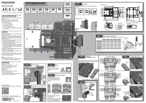
QUICK START<br />
EN<br />
<strong>ATyS</strong> S / <strong>Sd</strong><br />
Motorised Source Changeover Switch<br />
Installation and Commissioning<br />
STEP 1<br />
Cabinet / Back<br />
Plate Installation<br />
STEP 2<br />
Connecting the<br />
POWER Section<br />
STEP 3<br />
COMMAND /<br />
CONTROL terminal<br />
connections<br />
STEP 4<br />
Power Supply<br />
terminal<br />
connections<br />
STEP 5<br />
Emergency<br />
Handle mounting<br />
STEP 6<br />
Check<br />
STEP 7A<br />
Control by an external<br />
order (AUTO))<br />
STEP 7B<br />
Emergency Manual<br />
Operation<br />
STEP 1<br />
Attention: Ensure that the product is installed on a flat rigid surface.<br />
Orientation:<br />
40A -<br />
125A<br />
Installation<br />
Recommended Ok Ok<br />
All dimensions in mm.<br />
106<br />
94<br />
90.6<br />
11<br />
104.5<br />
26.5 27.5 26.5<br />
8<br />
37<br />
50<br />
50<br />
72<br />
143.5<br />
113<br />
15<br />
Preliminary operations<br />
Check the following upon delivery and after removal of the<br />
packaging:<br />
n Packaging and contents are in good condition.<br />
n The product reference corresponds to the order.<br />
n Contents should include:<br />
Qty 1 x <strong>ATyS</strong> S / <strong>Sd</strong> product<br />
Qty 1 x handle and storage clip<br />
Quick Start instruction sheet<br />
Qty 1 set of 3 terminal connectors<br />
Qty 1 set of 16 screws, nuts and washers for connecting<br />
the power section.<br />
STEP 7C<br />
Padlocking<br />
STEP 3<br />
Detailed fixing point: O° - 45° - 90°<br />
3<br />
2<br />
Ø 6.4<br />
115.2 74<br />
198<br />
16<br />
14<br />
72<br />
25<br />
44<br />
100<br />
181 42.5<br />
M6 125<br />
45<br />
Door cut-out for front panel mounting<br />
(7 modules):<br />
AUT<br />
Ue<br />
Warning<br />
Risk of electrocution, burns or injury to persons and /<br />
or damage to equipment.<br />
This Quick Start is intended for personnel trained in the<br />
installation and commissioning of this product. For further<br />
details refer to the product instruction manual available on<br />
the SOCOMEC website.<br />
n This product should always be installed and commissioned<br />
by qualified and approved personnel..<br />
n Maintenance and service operations should be performed<br />
by trained and authorised personnel.<br />
n Do not handle any control or power cables connected to<br />
the product when voltage may be, or may become present<br />
on the product, directly through the mains or indirectly<br />
through external circuits.<br />
n Always use an appropriate voltage detection device to<br />
confirm the absence of voltage.<br />
n Ensure that no metal objects are allowed to fall in the<br />
cabinet (risk of electrical arcing).<br />
Failure to observe good enginering practises as well as to<br />
follow these safety instructions may expose the user and<br />
others to serious injury or death.<br />
Aux 11<br />
IEC IEC<br />
60947-6-160947-3<br />
Risk of damage the device 14<br />
n In case 240V the 240Vproduct is dropped 21 or damaged in any way it<br />
Fn<br />
Class<br />
Ie 125A<br />
Ie 125A<br />
50/60Hz 50/60Hz<br />
is recommended PC to replace the complete product.<br />
24<br />
AC-33B AC-23A<br />
AC-32A<br />
01<br />
10/17kA<br />
Motorised Changeover Switch Motorised Changeover Switch<br />
Accessories<br />
6kV<br />
04 125A Ref : 95054012<br />
125A Ref : 95054012<br />
2,5kV<br />
50kA<br />
2A / 250V<br />
n Bridging bars 4P 2A 125A. / 24V<br />
n Control GB 14048-11 voltage transformer 400V -> 230V.<br />
n Terminal Shrouds Supply side / Load side.<br />
240V<br />
314<br />
n Secure 50Hz Connector Bracket.<br />
PC<br />
n Voltage taps. 315<br />
AC-33B<br />
AC-32A<br />
n DIN-rail 4 modules. 316<br />
<strong>ATyS</strong> S <strong>ATyS</strong> <strong>Sd</strong><br />
n ATS 6kV Controller type 317<strong>ATyS</strong> C30 + D10/D20.<br />
2,5kV<br />
C<br />
n ATS 50kA Controller type <strong>ATyS</strong> C40.<br />
For further details CTRL refer to the product instruction manual<br />
under chapter "Spares and Accessories"<br />
Icw / Icm<br />
Uimp power<br />
Uimp control<br />
Icc prospect.<br />
(fuse 125AgG)<br />
Ue<br />
Ue<br />
Fn<br />
Fn<br />
Class<br />
Ie 125A<br />
Ie 125A<br />
Icw / Icm<br />
Uimp power<br />
Uimp control<br />
Icc prospect.<br />
(fuse 125AgG)<br />
www.socomec.com<br />
To download brochures, catalogues and technical manuals:<br />
STEP 7B Manual NOK OK NOK<br />
I I I<br />
Operation AUT<br />
STEP 7C Padlocking mode (in position O)<br />
STEP IEC 4 IEC GB<br />
60947-6-160947-314048-11<br />
240V 240V<br />
50/60Hz 50/60Hz<br />
Class<br />
Ie 125A<br />
Ie 125A<br />
Icw / Icm<br />
PC<br />
AC-33B AC-23A<br />
AC-32A<br />
10/17kA<br />
Uimp power 6kV<br />
Uimp control 2,5kV<br />
Icc prospect.<br />
50kA<br />
STEP 6<br />
(fuse 125AgG)<br />
Check<br />
<strong>ATyS</strong> S<br />
125A<br />
Ref.: 88888888<br />
Whilst in manual mode, check the<br />
wiring and if ok power up the<br />
product.<br />
code à barres<br />
STEP 7A<br />
Automatic Operation<br />
Ensure that the emergency handle<br />
is not inserted in the product, and<br />
turn the mode selector to the AUT<br />
position.<br />
___________________________________________________________<br />
de KIT étiquettes <strong>ATyS</strong> S / <strong>Sd</strong> comprenant :<br />
ble d’étiquettes concernant le Sircover avant montage de la motorisation<br />
Impulse logic<br />
ble d’étiquettes à coller sur le produit fini<br />
order I<br />
order 0<br />
order II<br />
code barres KIT<br />
Contactor logic<br />
STEP3<br />
CONTROL /<br />
COMMAND Terminals<br />
Screw M3<br />
Tightening torque: min.: 0.5 Nm - max.: 0.6 Nm<br />
STEP 2<br />
Power Terminal Connections<br />
To be connected using terminal lugs, rigid or flexable busbars.<br />
40 A 63 A 80 A 10 0 A 125 A<br />
Minimum cable section<br />
Cu (mm 2 ) at Ith<br />
10 16 25 35 50<br />
Maximum cable<br />
section Cu (mm 2 )<br />
70 70 70 70 70<br />
Type of screw M6 M6 M6 M6 M6<br />
Recommended tightening<br />
torque (N.m)<br />
4.5 4.5 4.5 4.5 4.5<br />
Maximum tightening<br />
torque (N.m)<br />
5.4 5.4 5.4 5.4 5.4<br />
All values are indicative.<br />
1 2<br />
Ensure that the product is in manual mode and connect the<br />
product controls using the supplied connectors and suitable<br />
Motorised Changeover Switch Motorised Changeover Switch<br />
cable of section 1.5 - 2.5 mm ² .<br />
Fus. 4 A<br />
Fus. 4 A<br />
gG type<br />
gG type<br />
<strong>ATyS</strong> CTRL S<br />
<strong>ATyS</strong> <strong>Sd</strong>: 2 x 230 VAC<br />
317316 315314<br />
O I II<br />
AUX. CONTACTS<br />
<strong>ATyS</strong> S: 230 VAC<br />
<strong>ATyS</strong> <strong>Sd</strong><br />
Exemple de projet de KIT étiquettes <strong>ATyS</strong> S / <strong>Sd</strong>:<br />
101102<br />
201202<br />
04 03 24 23 14 13<br />
1 2<br />
317316 315314 04 03 24 23 14 13<br />
Bande STEP5 de Handle 80mm Storage Assembly de largeur et Marquages fixes<br />
O I II<br />
CTRL AUX. CONTACTS<br />
<strong>ATyS</strong> S DC version: 12 VDC / 24-48 VDC<br />
1<br />
301302<br />
Fus. 4 A<br />
gG type<br />
1<br />
STEP4<br />
*Torque<br />
*Torque<br />
Power Supply Terminals<br />
2<br />
Printing informations: 1 color Black. White paper 90g/m 2 .<br />
Printing size: 420x297. Final size 210x148. This page visible first.<br />
541 891 C - 05/13 - EN<br />
Non contractual document.<br />
Subject to change without notice.<br />
3x<br />
Ø 4-8 mm<br />
AUT<br />
<strong>ATyS</strong> s alim 1 source 230Vac<br />
position I<br />
position 0<br />
position II<br />
Imp. ≥60ms<br />
Close the contact corresponding to<br />
the desired position.<br />
Order Priority:<br />
I and II are equal priority over 0. Should<br />
I and II be closed simultaneously the<br />
product will not change position.<br />
maintened<br />
1 2<br />
<strong>ATyS</strong> 2 s alim 2 sources 230Vac<br />
317316 315314 04 03 24 23 14 13<br />
O I II<br />
CTRL<br />
401402<br />
AUX. CONTACTS<br />
DC<br />
Fus. 4 A<br />
gG type<br />
Screw M3<br />
*Tightening torque:<br />
min.: 0.5 Nm<br />
max.: 0.6 Nm
QUICK START<br />
FR<br />
<strong>ATyS</strong> S / <strong>Sd</strong><br />
Inverseur de sources motorisé<br />
Mise en service<br />
STEP 1<br />
Montage du<br />
produit sur<br />
platine / armoire<br />
STEP 2<br />
Raccordement<br />
partie<br />
PUISSANCE<br />
STEP 3<br />
Raccordement<br />
bornier CONTRÔLE /<br />
COMMANDE<br />
STEP 4<br />
Raccordement<br />
bornier<br />
ALIMENTATION<br />
STEP 5<br />
Montage de la<br />
poignée<br />
STEP 6<br />
VÉRIFICATION<br />
STEP 7A<br />
Commande électrique<br />
par ordre extérieur<br />
(AUTO)<br />
STEP 7B<br />
Commande<br />
manuelle par poignée<br />
de secours<br />
STEP 1<br />
Sens de montage. Attention : le produit doit toujours être installé sur<br />
une surface plane et rigide.<br />
40A -<br />
125A<br />
Montage<br />
Recommandé Ok Ok<br />
Dimensions en mm.<br />
106<br />
94<br />
90.6<br />
11<br />
104.5<br />
26.5 27.5 26.5<br />
8<br />
37<br />
50 50<br />
72<br />
143.5<br />
113<br />
15<br />
Opérations préalables<br />
Vérifiez les points suivants au moment de la réception du<br />
colis :<br />
n le bon état de l’emballage et du produit<br />
n la conformité de la référence du produit avec votre<br />
commande<br />
n le contenu de l’emballage :<br />
1 produit "<strong>ATyS</strong> S / <strong>Sd</strong>"<br />
1 sachet poignée + clip de fixation<br />
1 Quick Start<br />
1 lot avec 3 connecteurs<br />
Kit de visserie pour le raccordement de la partie puissance<br />
(16 vis - 16 écrous - 16 rondelles).<br />
STEP 7C<br />
Cadenassage<br />
de l'<strong>ATyS</strong><br />
STEP 3<br />
Détail point de fixation : O° - 45° - 90°<br />
3<br />
2<br />
Ø 6.4<br />
115.2 74<br />
198<br />
16<br />
14<br />
72<br />
25<br />
44<br />
100<br />
181 42.5<br />
Découpe de la face avant (7 modules) :<br />
M6 125<br />
45<br />
AUT<br />
Danger et avertissement<br />
Risque d'électrocution, de brûlures ou de blessures aux<br />
personnes et/ou de dommages à l'équipement.<br />
Cette Quick Start est destinée à un personnel formé à<br />
l'installation du produit ; pour une compréhension complète,<br />
référez-vous à la notice.<br />
n Ce système doit toujours être installé et mis en service<br />
par du personnel qualifié et habilité.<br />
n Les opérations de maintenance et d’entretien doivent être<br />
réalisées par du personnel formé et autorisé.<br />
n Veillez à ne pas manipuler les câbles raccordés à la<br />
puissance ou aux commandes de l’<strong>ATyS</strong> dès lors qu’une<br />
tension est susceptible d’être présente sur le produit.<br />
n Utilisez toujours un dispositif de détection de tension<br />
approprié pour confirmer l’absence de tension.<br />
n Prenez garde à la chute de matériels métalliques dans<br />
l’armoire (risque d’arc électrique).<br />
Le non-respect de ces consignes de sécurité exposera<br />
l’intervenant et son entourage à des risques de dommages<br />
corporels graves susceptibles d’entraîner la mort.<br />
STEP 2<br />
Raccordement de la puissance<br />
A raccorder avec des cosses ou des barres rigides/flexibles.<br />
40 A 63 A 80 A 100 A 125 A<br />
Section minimale<br />
câble Cu (mm 2 ) à Ith<br />
10 16 25 35 50<br />
Section maximale<br />
câble Cu (mm 2 )<br />
70 70 70 70 70<br />
Type de vis M6 M6 M6 M6 M6<br />
Couple de serrage<br />
conseillé (N.m)<br />
4.5 4.5 4.5 4.5 4.5<br />
Couple de serrage<br />
maxi (N.m)<br />
5.4 5.4 5.4 5.4 5.4<br />
Valeurs données à titre indicatif.<br />
1<br />
2<br />
e<br />
n<br />
lass<br />
e 125A<br />
e 125A<br />
Risque de détérioration Aux 11 de l'appareil<br />
IEC IEC<br />
n En 60947-6-1 cas 60947-3 de chute du produit, 14 il est préférable de le<br />
remplacer.<br />
240V 240V<br />
21<br />
50/60Hz 50/60Hz<br />
PC<br />
24<br />
AC-33B AC-23A<br />
Accessoires<br />
AC-32A<br />
01<br />
10/17kA<br />
Motorised Changeover Switch Motorised Changeover Switch<br />
n Barres 6kV de pontage 4P 125A. 04 125A Ref : 95054012<br />
125A Ref : 95054012<br />
2,5kV<br />
n Transformateur 50kA<br />
2A / de 250V tension de commande 400V -> 230V.<br />
2A / 24V<br />
n Cache-bornes Source / Charge.<br />
GB 14048-11<br />
n Clip de maintien des connecteurs<br />
240V<br />
n Prise de tension. 314<br />
50Hz<br />
PC<br />
n Rail DIN 4 modules. 315<br />
AC-33B<br />
n Contrôleur AC-32A <strong>ATyS</strong> 316 C30 + D10/D20.<br />
<strong>ATyS</strong> S <strong>ATyS</strong> <strong>Sd</strong><br />
n Contrôleur<br />
6kV<br />
<strong>ATyS</strong> C40.<br />
317<br />
Pour<br />
2,5kV<br />
de plus amples détails, C veuillez consulter la notice de<br />
50kA<br />
montage chapitre - Pièces de rechange et accessoires)<br />
CTRL<br />
cw / Icm<br />
imp power<br />
imp control<br />
cc prospect.<br />
fuse 125AgG)<br />
e<br />
n<br />
lass<br />
e 125A<br />
e 125A<br />
cw / Icm<br />
imp power<br />
imp control<br />
cc prospect.<br />
fuse 125AgG)<br />
STEP 7C Mode cadenassage (en position O)<br />
STEP IEC 4 IEC GB<br />
60947-6-160947-314048-11<br />
240V 240V<br />
50/60Hz 50/60Hz<br />
Class<br />
Ie 125A<br />
Ie 125A<br />
Icw / Icm<br />
PC<br />
AC-33B AC-23A<br />
AC-32A<br />
10/17kA<br />
Uimp power 6kV<br />
Uimp control 2,5kV<br />
Icc prospect.<br />
50kA<br />
STEP 6<br />
(fuse 125AgG)<br />
Vérification<br />
<strong>ATyS</strong> S<br />
125A<br />
Ref.: 88888888<br />
Toujours en mode manuel, vérifier<br />
le code câblage à barres du produit ; si celui-ci<br />
est correct, alimenter le produit.<br />
STEP 7A<br />
S'assurer que la poignée n'est pas<br />
insérée dans le produit et tourner le<br />
sélecteur/clef en position AUT.<br />
Opération automatique<br />
e KIT étiquettes <strong>ATyS</strong> S / <strong>Sd</strong> comprenant :<br />
ble d’étiquettes concernant le Sircover avant montage de la motorisation<br />
Logique impulsionnelle<br />
ble d’étiquettes à coller sur le produit fini<br />
ordre I<br />
www.socomec.com<br />
Espace téléchargement : brochures, catalogues et notices :<br />
STEP 7B Opération NOK OK NOK<br />
I I I<br />
manuelle AUT<br />
___________________________________________________________<br />
ordre 0<br />
ordre II<br />
code barres KIT<br />
Logique contacteur<br />
STEP3<br />
Bornier<br />
CONTRÔLE / COMMANDE<br />
1 2<br />
Le produit doit être en mode manuel. Raccorder le produit<br />
avec des câbles de 1,5 à 2,5 mm 2 sur les connecteurs<br />
Motorised Changeover Switch Motorised Changeover Switch<br />
fournis.<br />
Fus. 4 A<br />
Fus. 4 A<br />
type gG<br />
type gG<br />
<strong>ATyS</strong> S<br />
<strong>ATyS</strong> <strong>Sd</strong> : 2 x 230 VAC<br />
317316 315314<br />
O I II<br />
CTRL CONTACT AUX.<br />
<strong>ATyS</strong> S : 230 VAC<br />
<strong>ATyS</strong> <strong>Sd</strong><br />
Vis M3 - Couple de serrage : mini : 0,5 Nm - maxi : 0,6 Nm<br />
Exemple de projet de KIT étiquettes <strong>ATyS</strong> S / <strong>Sd</strong>:<br />
101102<br />
201202<br />
04 03 24 23 14 13<br />
1 2<br />
317316 315314 04 03 24 23 14 13<br />
Bande STEP5 de Montage 80mm de la poignée de largeur et Marquages fixes<br />
O I II<br />
CTRL CONTACT AUX.<br />
<strong>ATyS</strong> S version DC : 12 VDC / 24-48 VDC<br />
1<br />
301302<br />
Fus. 4 A<br />
type gG<br />
STEP4<br />
*Serrage<br />
*Serrage<br />
Bornier ALIMENTATION<br />
541 891 C - 05/13 - FR<br />
Document non contractuel.<br />
Soumis à changements.<br />
3x<br />
Ø 4-8 mm<br />
AUT<br />
<strong>ATyS</strong> s alim 1 source 230Vac<br />
position I<br />
position 0<br />
position II<br />
Imp. ≥60ms<br />
Fermer le contact correspondant à<br />
la position souhaitée.<br />
Priorité des ordres :<br />
I et II sont prioritaires à O.<br />
En cas d'appui simultané sur I et II,<br />
il n'y a pas d'action.<br />
maintenu<br />
1 2<br />
<strong>ATyS</strong> 2 s alim 2 sources 230Vac<br />
317316 315314 04 03 24 23 14 13<br />
O I II<br />
CTRL<br />
CONTACT AUX.<br />
401402<br />
DC<br />
Fus. 4 A<br />
type gG<br />
Vis M3<br />
*Couple de serrage :<br />
mini : 0,5 Nm<br />
maxi : 0,6 Nm