IOMSUNMOXX00-GB 00.indd - Socomec
IOMSUNMOXX00-GB 00.indd - Socomec
IOMSUNMOXX00-GB 00.indd - Socomec

Create successful ePaper yourself
Turn your PDF publications into a flip-book with our unique Google optimized e-Paper software.
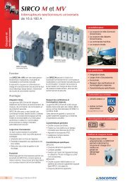
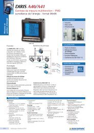
2.DESCRIPTION OF THE SYSTEM2.2-2 SUNSYS pro R02 with the door open and the two 33 kW power modulesRS232RS232ButtonTEST(option)ButtonRESET(option)Communication slotsModule AModule A outputdisconnection switchModule B outputdisconnection switchModule BDisconnection switches with fuse(see detail below)IEC320 AUX output for assistanceIEC320 AUX power inputInverter output disconnection switchModule B input disconnection switchModule A input disconnection switchDetailDisconnectionswitches with fuse1 2 3 4 51 Disconnection switch for isolation controller (option)2 Disconnection switch for isolation controller (option)3 Disconnection switch for IEC320 connector AUX power supply4 Disconnection switch for IEC320 connector for assistance5 Fan fuses10 SUNSYS pro - SUNSYS station - Ref.: <strong>IOMSUNMOXX00</strong>-<strong>GB</strong> 00
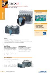
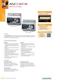
2. DESCRIPTION OF THE SYSTEM2.2-3 SUNSYS station P03 with the door open and the three 33 kW power modulesRS232RS232Communication slotsModule A output disconnection switchModule B output disconnection switchModule C output disconnection switchInverter output disconnection switchButtonTEST(option)ButtonRESET(option)Module AENGLISHModule BModule CDisconnection switches with fuse (see detail below)IEC320 AUX power inputIEC320 AUX output for assistanceModule A input disconnection switchModule B input disconnection switchModule C input disconnection switchDetailDisconnectionswitcheswith fuse1 2 3 4 51 Disconnection switch for isolation controller (option)2 Disconnection switch for isolation controller (option)3 Disconnection switch for IEC320 connector AUX power supply4 Disconnection switch for IEC320 connector for assistance5 Fan fuseSUNSYS pro - SUNSYS station - Ref.: <strong>IOMSUNMOXX00</strong>-<strong>GB</strong> 0011
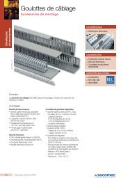
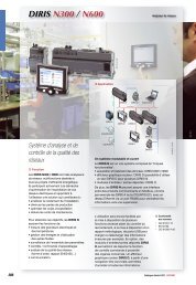
2.DESCRIPTION OF THE SYSTEMThe SUNSYS series covers a range of power from 33.3 to 100 kW and consists of 1, 2 or 3 modules of 33.3 kW each.Each module converts the energy provided by the solar panels, using a Maximum Power Point Tracking (MPPT) algorithm to fullyexploit the features of the photovoltaic cells.The DC terminals of all modules can be connected to the same photovoltaic field (centralised modular inverter with single MPPT),or can have different photovoltaic fields (centralised multi-string inverter with separate MPPTs).2.2-4 Simplified wiring diagram of the SUNSYS pro R01 systemDC +/–Photovoltaic fieldX10AQ1AOptionSPD-INQ3AIMDGNDT1IMDOptionIMDOptionearthing kit + IMDK1X90X10AQ70OptionSPD-OUTX903Ph+PEAC main network2.2-5 Simplified wiring diagram of the SUNSYS pro R02 systemPhotovoltaic fieldDC +/–Photovoltaic fieldDC +/–X10AX10BOptionCommon DCQ1AQ1BQ3AOptionSPD-INIMDGNDOptionearthing kit + IMDQ3BOptionSPD-INT1K1IMDOptionIMDX90X10BX10AQ70OptionSPD-OUTX903Ph+PEAC main network12 SUNSYS pro - SUNSYS station - Ref.: <strong>IOMSUNMOXX00</strong>-<strong>GB</strong> 00
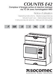
2. DESCRIPTION OF THE SYSTEM2.2-6 Simplified wiring diagram of the SUNSYS station P03 system (with SUNSYS station T03 transformer)FieldphotovoltaicFieldphotovoltaicFieldphotovoltaicDC +/– DC +/– DC +/–X10AX10BX10COptionCommon DCInverterSUNSYS station P03GNDQ1AOptionSPD-INQ1BOptionSPD-INQ1COptionSPD-INIMDX90X10CX10BX10AOptionearthing kit + IMDQ3AQ3BX90Q3CIMDOptionIMDENGLISH3Ph+PEAC main networkPower supply networkTransformerSUNSYS station T03X103PhT1X90X10K1OptionSPD-OUTQ70X903Ph+PEAC main networkSUNSYS pro - SUNSYS station - Ref.: <strong>IOMSUNMOXX00</strong>-<strong>GB</strong> 0013
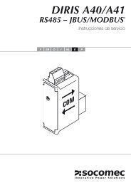
2.DESCRIPTION OF THE SYSTEM2.2-7 System principle diagram2.2-8 Centralised modular inverter 2.2-9 Centralised multi-string inverterDCACDCACDCACDCACDCACDCACThe SUNSYS series covers a range of power from 33.3 to 100 kW and consists of 1, 2 or 3 modules of 33.3 kW each.Each module converts the energy provided by the solar panels, using a Maximum Power Point Tracking (MPPT) algorithm to fullyexploit the features of the photovoltaic cells.The DC terminals of all modules can be connected to the same photovoltaic field (centralised modular inverter with single MPPT),or can have different photovoltaic fields (centralised multi-string inverter with separate MPPTs).14 SUNSYS pro - SUNSYS station - Ref.: <strong>IOMSUNMOXX00</strong>-<strong>GB</strong> 00
2.DESCRIPTION OF THE SYSTEM2.3. TECHNICAL DATASUNSYS pro R01SUNSYS pro R02SUNSYS station P03 withSUNSYS station T03SUNSYS station P03DC inputDC rated current 80 A 160 A 240 AMax. DC voltage900 VStop voltage350 VMPP field450 to 850 VMPPT no. 1 1-2 1-3AC outputRated power 33.3 kW 66.7 kW 100 kWMaximum power (30 min.) 36.6 kW 73.4 kW 110 kWAC voltageOutput voltage 400 V 3ph 280 V 3phProtection 63 A curve D 125 A curve D 200 A curve DPower factor ≥0.99Distortion factor
3. PREREQUISITES3.1. INSTALLATION SITE CONDITIONSThe installation site must meet the following requirements:- The inverter is designed for use within non-air-conditioned rooms in accordance with standard IEC 62109-1. Th inverter is notdesigned for outdoor use.- The foundations must be able to withstand the relevant weight (inverter, transportation device) and suited to the base. Stabilitymust also be guaranteed.- The ambient temperatures, relative humidity and altitude of the installation site are indicated in the technical data table.- Avoid environments which are dusty or which contain dust from conductive or corrosive materials (e.g. dust from metal or chemicalsolutions).- The inverter has front access for handling devices; nevertheless, a space of at least 1.5 metres should be left free at the front ofthe inverter for any maintenance work required.- The rear of the inverter must be at least 40 cm away from the wall or other obstacles to guarantee sufficient ventilation (see figure).3.1-140 cmENGLISHSUNSYS SUNSYS SUNSYS1.5 mfree areaSUNSYS pro - SUNSYS station - Ref.: <strong>IOMSUNMOXX00</strong>-<strong>GB</strong> 0017
4. TRANSPORT AND UNWRAPPING4.1-1 4.1-24.1-3 Remove the woodenprotection4.1-4 Position the inverter in the installation zone. The SUNSYS station P03 inverter must be fixed to the floorSUNSYS station P03 inverterSUNSYS station T03transformer cabinetRear side40 cmWARNING!After completing all the procedures, fit the protective skirting18 SUNSYS pro - SUNSYS station - Ref.: <strong>IOMSUNMOXX00</strong>-<strong>GB</strong> 00
5. INSTALLATIONDANGER!Risk of electric shock from live device parts!In the event of system maintenance, carry out the following steps beforehand:• Disconnect the photovoltaic system.• Make sure the photovoltaic system cannot be restarted.• Make sure the mains electricity supply has been disconnected.• Earth the device units and short-circuit them.• Cover or separate the nearby live device units.• Before working on the circuits upstream make sure the inverter is disconnected by opening the DC disconnection switches.DANGER!Risk of electric shock from live device parts!SUNSYS pro and SUNSYS station can be connected to a maximum of three power supplies:1 DC cable - Photovoltaic generator power supply (separated for the three modules or shared)2 AC cable - Power from the mains network, supplied by the electricity company3 AC cable - Auxiliary power supply• Before carrying out any work, make sure the electricity supply has been disconnected.• All DC power supplies should be considered as part of the same circuit, even in the configuration with centralised multistringinverter. Before carrying out any work, make sure all electricity supplies have been disconnected.ENGLISH5 minDANGER!Risk of electric shock from live device parts!The intermediate inverter circuit may be live even after it has been deactivated.• Wait 5 minutes for the power to disperse and make sure that there is none remaining.DANGER!Risk of electric shock from live device parts!The photovoltaic modules are live as soon as they are exposed to sunlight.• Take suitable measures and make sure there is no power remaining.SUNSYS pro and SUNSYS station are designed for instant application. Only the AC and DC cables coming from outsidemust be installed and the inverter configured.5.1. ELECTRICAL INSTALLATION REQUIREMENTSThe installation and system must comply with existing national legislation.The fixed power distribution unit must include protection and disconnection for the main AC network for the auxiliary network.The following table indicates the sizing of AC protection devices that will ensure correct installation.Inverter sizeMagneto-thermal switchNetwork cable cross-sectionDifferential AC protectionMain AC (mm 2 ) (1)protecting the main ACnetwork (2)(optional)33 kW min. 16 / max. 120 63 A type D 0.3 A type AC or A66 kW min. 35 / max. 120 125 A type D 0.3 A type AC or A100 kW min. 70 / max. 120 200 A type D 0.3 A type AC or A(1) Determined by the size of the terminals(2) Recommended magneto-thermal switch: three poles with intervention threshold ≥ 10 InSUNSYS pro - SUNSYS station - Ref.: <strong>IOMSUNMOXX00</strong>-<strong>GB</strong> 0019
5. INSTALLATIONThe auxiliary power supply socket must be protected with a 16 A magneto-thermal switch, curve C, and from category 2 overvoltagesor greater.The following table indicates the sizing of the wires originating from the photovoltaic generator for correct installation.Inverter sizePV generator cable cross-section in case of PV generator cable cross-section in case ofshared DC inputs (mm 2 ) (1)separate DC inputs (mm 2 ) (2)33 kW min. 25 / max. 120 (M8) N.A.66 kW min. 50 / max. 120 (M8) min. 25 / max. 120 (M8)100 kW min. 95 / max. 120 (M8) min. 25 / max. 120 (M8)(1) Determined by the size of the terminals(2) Up to 2 cables can also be connected at the same point, max. 2x50 mm 2WARNING!The inverter is designed for transient over-voltages in category II installations for AC terminals. If the inverter may besubjected to transient over-voltages in category III installations, protective SPDs must be provided for the AC power supplynetwork. The SPDO option, designed to protect against category III over-voltages, can be fitted directly to the inverter. If itis used, the distance between the inverter and type I centralised SPD protection must be ≥15 m.WARNING!The inverter is designed for transient over-voltages in category II installations for DC terminals. If the inverter may be subjectto transient over-voltages in category III installations, or if the distance from the SPDs in the photovoltaic field is excessive,protective SPDs must be fitted near the inverter. The SPDI option, designed to protect against over-voltages in photovoltaicapplications, can be fitted directly to the inverter.NOTEDC inputs do not require protection against over-voltages, if fewer than three inverter modules are connected to the samephotovoltaic generator.NOTEFunctional panel earthing (optional): for correct operation, some types of photovoltaic panel require one of the two poles tobe earthed. The special optional kit (GND) can be used to earth the positive or negative pole of the photovoltaic generator.For further details and instructions, please refer to the kit (GND) installation and operating manual.IT SYSTEM:With the photovoltaic panels isolated from earth, the circuit consisting of the panels and the inverter is configured like an ITsystem. We therefore recommend a permanent isolation controller is used in the system or built into the inverter (IMD option).20 SUNSYS pro - SUNSYS station - Ref.: <strong>IOMSUNMOXX00</strong>-<strong>GB</strong> 00
5. INSTALLATION5.2. CONNECTING THE PHOTOVOLTAIC GENERATOR AND MAIN AC NETWORKTO THE POWER TERMINALS OF THE SUNSYS PRO R01 INVERTERThe inverter is connected to the photovoltaic generator via the DC terminals, and to the main AC network via the AC power terminals.• Apply the ring terminals to the cables.• Remove the panels protecting the connection zone in front of the terminals.• Fix the protection wire (PE) to the connection terminal.• Fix the wires (L1, L2, L3) to the connection terminals.• Fix the wires (L+,L-) to the connection terminals.• Fix the cables to the cable support guide using cable fastening brackets.• Reposition the panels protecting the connection zone in front of the terminals.DANGER!Risk of electric shock from live device parts!The inverter can be connected to a maximum of three power supplies:1 DC cable - Photovoltaic generator power supply (separated for the three modules or shared)2 AC cable - Power from the mains network, supplied by the electricity company3 AC cable - Auxiliary power supply• Before carrying out any work, make sure the electricity supply has been disconnected.• All DC power supplies should be considered as part of the same circuit, even in the configuration with centralised multistringinverter. Before carrying out any work, make sure all electricity supplies have been disconnected.ENGLISHNOTETorque for the DC and AC power terminals: 20 Nm5.2-1Ring terminalsCable fastening bracketsL1 L3 PE L–L2 L+KeyPE: Connection terminal for the protective earth wire (PE)L1, L2, L3: Connection terminals for the main AC network 3NL+, L-: DC connection terminals for the photovoltaic generatorSUNSYS pro - SUNSYS station - Ref.: <strong>IOMSUNMOXX00</strong>-<strong>GB</strong> 0021
5. INSTALLATION5.3. CONNECTING THE PHOTOVOLTAIC GENERATOR AND MAIN AC NETWORKTO THE POWER TERMINALS OF THE SUNSYS PRO R02 INVERTERThe inverter is connected to the photovoltaic generator via the DC terminals, and to the main AC network via the AC power terminals.• Attach the ring terminals to the cables.• Remove the panels protecting the connection zone in front of the terminals.• Fix the protection wire (PE) to the connection terminal.• Fix the wires (L1, L2, L3) to the connection terminals.• Fix the wires (L+,L-) to the connection terminals.• Fix the cables to the cable support guide using cable fastening brackets.• Reposition the panels protecting the connection zone in front of the terminals.DANGER!Risk of electric shock from live device parts!The inverter can be connected to a maximum of three power supplies:1 DC cable - Photovoltaic generator power supply (separated for the three modules or shared)2 AC cable - Power from the mains network, supplied by the electricity company3 AC cable - Auxiliary power supply• Before carrying out any work, make sure the electricity supply has been disconnected.• All DC power supplies should be considered as part of the same circuit, even in the configuration with centralised multistringinverter. Before carrying out any work, make sure all electricity supplies have been disconnected.NOTETorque for the DC and AC power terminals: 20 Nm5.3-1Ring terminalsCable fastening bracketsL1 L3L2 PE L– L+KeyPE: Connection terminal for the protective earth wire (PE)L1, L2, L3: Connection terminals for the main AC network 3NL+, L-: DC connection terminals for the photovoltaic generator22 SUNSYS pro - SUNSYS station - Ref.: <strong>IOMSUNMOXX00</strong>-<strong>GB</strong> 00
5. INSTALLATIONThe inverter is connected to the photovoltaic generator via the DC terminals, and to the main AC network via the AC power terminals.• Apply the ring terminals to the cables.• Remove the panels protecting the connection zone in front of the terminals.• Remove the sharing bar for the DC terminals if using a centralised multi-string inverter.• Fix the protection wire (PE) to the connection terminal.• Fix the wires (L1, L2, L3) to the connection terminals.• Fix the wires (L+,L-) to the connection terminals.• Fix the cables to the cable support guide using cable fastening brackets.• Reposition the panels protecting the connection zone in front of the terminals.DANGER!Risk of electric shock from live device parts!The inverter can be connected to a maximum of three power supplies:• Before carrying out any work, make sure the electricity supply has been disconnected.5.3-2NOTETorque for the DC and AC power terminals: 20 NmENGLISHRing terminalsCable fastening bracketsL1L3L2 PE L+ L– L+ L–Module B Module AKeyPE: Connection terminal for the protective earth wire (PE)L1, L2, L3: Connection terminals for the main AC network 3NL+, L-: DC terminals connecting the photovoltaic generator to module BL+, L-: DC terminals connecting the photovoltaic generator to module ASUNSYS pro - SUNSYS station - Ref.: <strong>IOMSUNMOXX00</strong>-<strong>GB</strong> 0023
5. INSTALLATION5.4. CONNECTING THE PHOTOVOLTAIC GENERATOR AND MAIN AC NETWORKTO THE POWER TERMINALS OF THE SUNSYS STATION P03 INVERTERThe inverter is connected to the photovoltaic generator via the DC terminals, and to the main AC network via the AC power terminals.• Attach the ring terminals to the cables.• Remove the panels protecting the connection zone in front of the terminals.• Fix the protection wire (PE) to the connection terminal.• Fix the wires (L+,L-) to the connection terminals.• Fix the power cables supplied between the transformer cabinet and the inverter.• Fix the signal cables supplied between the transformer cabinet and the inverter.• Fix the wires (L1, L2, L3) to the connection terminals on the transformer cabinet.• Fix the cables to the cable support guide using cable fastening brackets.• Reposition the panels protecting the connection zone in front of the terminals.DANGER!Risk of electric shock from live device parts!The inverter can be connected to a maximum of three power supplies:• Before carrying out any work, make sure the electricity supply has been disconnected.NOTETorque for the DC and AC power terminals: 20 Nm5.4-1Terminalsring typeBracketsfor fasteningcablesL1 L3PE L2L1 L3 CablesL2 for signalL– L+CablessuppliedKeyPE: Connection terminal for the protective earth wire (PE)L1, L2, L3: Connection terminals for the main AC network 3NL+, L-: DC terminals connecting the photovoltaic generator to module CL+, L-: DC terminals connecting the photovoltaic generator to module BL+, L-: DC terminals connecting the photovoltaic generator to module A24 SUNSYS pro - SUNSYS station - Ref.: <strong>IOMSUNMOXX00</strong>-<strong>GB</strong> 00
5. INSTALLATIONThe inverter is connected to the photovoltaic generator via the DC terminals, and to the main AC network via the AC power terminals.• Attach the ring terminals to the cables.• Remove the panels protecting the connection zone in front of the terminals.• Remove the sharing bar for the DC terminals if using a centralised multi-string inverter.• Fix the protection wire (PE) to the connection terminal.• Fix the wires (L+,L-) to the connection terminals.• Fix the power cables supplied between the transformer cabinet and the inverter.• Fix the signal cables supplied between the transformer cabinet and the inverter.• Fix the wires (L1, L2, L3) to the connection terminals on the transformer cabinet.• Fix the cables to the cable support guide using cable fastening brackets.• Reposition the panels protecting the connection zone in front of the terminals.DANGER!Risk of electric shocks from live device parts!The inverter can be connected to a maximum of three power supplies:• Before carrying out any work, make sure the electricity supply has been disconnected.5.4-2NOTETorque for the DC and AC power terminals: 20 NmENGLISHTerminalsring typeBracketsfor fasteningcablesL1 L3PE L2L1 L3 CablesL2 for signal L+ L– L+ L– L+ L–CablessuppliedKeyPE: Connection terminal for the protective earth wire (PE)L1, L2, L3: Connection terminals for the main AC network 3NL+, L-: DC terminals connecting the photovoltaic generator to module CL+, L-: DC terminals connecting the photovoltaic generator to module BL+, L-: DC terminals connecting the photovoltaic generator to module AModule C Module B Module ASUNSYS pro - SUNSYS station - Ref.: <strong>IOMSUNMOXX00</strong>-<strong>GB</strong> 0025
5. INSTALLATION5.5. AUXILIARY POWER SUPPLY5.5-1 Socket for AUX power supplyPower supplyInterface protection jumperThe inverter equipment is powered by a special 230 V single-phase line. The auxiliary voltage must be connected to the relevantsocket (see figure).DANGER!Risk of electric shock from live device parts!The inverter can be connected to a maximum of three power supplies:• Before carrying out any work, make sure the electricity supply has been disconnected.WARNING!Risk of damage to the system if not observed!The auxiliary power supply cable must be fitted with a 16 A max. protection device.5.6. OPTIONAL INPUT FOR EXTERNAL INTERFACE PROTECTIONIf local electricity supply company connection rules specify that external interface protection must be used, the external protectionoutput signal (dry contact) can be used to control the internal contactor for the Sunsys Modular inverter, removing the jumper infigure 5.5-1.26 SUNSYS pro - SUNSYS station - Ref.: <strong>IOMSUNMOXX00</strong>-<strong>GB</strong> 00
6. OPERATING MODES6.1. ACTIVATING THE INVERTER FOR THE FIRST TIMEThe first time the equipment is switched on the system displays the Activation page; a guided procedure follows on the screen. Inparticular, when scrolling the menu options it is possible choose the user interface language, set the system configuration and thecountry in which the equipment is installed.System setupIn the system setup menu set the number of modules installed in the cabinet from 1 to 3 depending on the size of the machine (33kW, 66 kW or 100 kW).NOTEAll the modules inside the cabinet must be powered in order to successfully complete the configuration procedure. Whenfollowing the guided procedure if more than one module is fitted the type of connection on the DC side is required for each.This can be:• Stand-Alone if the module in question is connected individually to an array of photovoltaic panels (see figure 2.2-9Centralised Multi-String Inverter);• Modular if the module in question is connected in parallel with other modules to the same array of photovoltaic panels(see figure 2.2-8 Centralised Modular Inverter).Confirm the settings.Transformer configurationWhen installing the 100 kW system (3 modules) make sure the type of transformer selected in the Transformer Typemenu corresponds to the installed device. The default transformer type 'SOCOMEC (built-in)'; only select 'External' ifthe machine is not fitted with a SOCOMEC transformer.ENGLISHCountry SettingChoosing the country is particularly important, as it leads to the automatic configuration of the inverter in compliance with the standardsin force in that country.All other parameters appearing in the 'initial startup' guided procedure menu will therefore be configured correctly and will not usuallyneed to be changed, unless the local electricity supply company has specific requirements which need to be met.NOTEThe country of installation cannot be changed after the first machine activation. If this becomes necessary, contact anauthorised SOCOMEC service centre. Call the freephone number 800.00.80.85NOTEThe installer is responsible for carrying out the procedure in accordance with national standards.Activation codeDuring the initial startup procedure the four-digit activation code must be entered:The activation code is supplied directly by the relevant Service Centre after the equipment serial number is entered, as shown in thefollowing message, and ENTER is pressed.SUNSYS pro - SUNSYS station - Ref.: <strong>IOMSUNMOXX00</strong>-<strong>GB</strong> 0027
6. OPERATING MODESNOTEIf the code is not entered, the 'initial startup' procedure cannot be completed and the equipment will be prevented fromoperating. When contacting the Service Centre for the activation code, you can obtain detailed information relating to theservices available for the equipment in question, in addition to regular preventive maintenance schedules. Call the freephonenumber 800.00.80.85Completing the 'initial startup' procedureThe 'initial startup' procedure may only be completed using the confirmation menu option that appears if the activation code hasbeen entered.At this point the inverter is activated and ready.If the IMD permanent isolation controller (optional) is installed, check its configuration via the SERVICE menu. For setting details,pleaser refer to the sheet supplied with the IMD.6.2. SWITCHING ON THE INVERTERSwitch on the inverter as follows (Figures 6.3-1, 6.3-2, 6.3-3):• Set all the DC input Q1 disconnection switches for the modules to position 1.• Set the inverter AC output Q70 disconnection switch to position 1.• Set all the AC output Q3 disconnection switches for the modules to position 1.This procedure is also described in the menu COMMANDS -> Start Procedure.6.3. SWITCHING OFF THE INVERTERSwitch off the inverter as follows (Figures 6.3-1, 6.3-2, 6.3-3):• Set all the AC output Q3 disconnection switches for the modules to position 0.• Set the inverter AC output Q70 disconnection switch to position 0.• Set all the DC input Q1 disconnection switches for the modules to position 0.The inverter is now switched off. This procedure is also described in the menu COMMANDS -> Stop Procedure.If the auxiliary power supply also needs to be cut off, disconnect the cable from the Auxiliary Power Supply Input socket or breakthe fuse connection. This procedure will switch off all the auxiliary inverter equipment, including the system controller and the mimicpanel. The general AC power contactor for the machine will also be opened.DANGER!Risk of electric shock from live device parts!The inverter can be connected to a maximum of three power supplies:1) DC cable - Power from the photovoltaic generator2) AC cable - Power from the mains network, supplied by the electricity company3) AC cable - Auxiliary power supply• Before carrying out any work, make sure the electricity supply has been disconnected.28 SUNSYS pro - SUNSYS station - Ref.: <strong>IOMSUNMOXX00</strong>-<strong>GB</strong> 00
6. OPERATING MODES5 minDANGER!Risk of electric shock from live device parts!The intermediate inverter circuit may be live even after it has been deactivated.Wait 5 minutes for the power to disperse and make sure that there is none remaining.6.3-1 Switching SUNSYS pro R01 on and offQ3 Module A outputdisconnection switchENGLISHQ70 Inverter outputdisconnection switchQ1 Module A inputdisconnection switchSUNSYS pro - SUNSYS station - Ref.: <strong>IOMSUNMOXX00</strong>-<strong>GB</strong> 0029
6. OPERATING MODES6.3-1 Switching SUNSYS pro R02 on and offQ3 Module A outputdisconnection switchQ3 Module B outputdisconnection switchQ70 Inverter outputdisconnection switchQ1 Module B inputdisconnection switchQ1 Module A inputdisconnection switch30 SUNSYS pro - SUNSYS station - Ref.: <strong>IOMSUNMOXX00</strong>-<strong>GB</strong> 00
6. OPERATING MODES6.3-1 Switching SUNSYS station P03 on and offQ3 Module A output disconnection switchQ3 Module B output disconnection switchQ3 Module C output disconnection switchQ70 Inverter output disconnection switchENGLISHQ1 Module C input disconnection switchQ1 Module B input disconnection switchQ1 Module A input disconnection switchSUNSYS pro - SUNSYS station - Ref.: <strong>IOMSUNMOXX00</strong>-<strong>GB</strong> 0031
7. MIMIC PANEL7.1-1BCAThe LCD mimic panel (figure 7.1) on the door provides all the information relating to operating status, electrical measurements,access to controls and configuration parameters.The information is divided into three parts:A. multicoloured luminous bar identifying the inverter statusB. alphanumerical information which, via a menu layout, provides details of any alerts, recorded values, commands and parametersC. button usage:• ESC: exit the menu/parameter/current action;• UP: scroll upwards through the menu/available values; while a parameter is being modified it increases the value every time itis pressed;• DOWN: scroll downwards through the menu/available values; while a parameter is being modified it decreases the value everytime it is pressed;• ENTER: enter the menu suggested on the display or confirm the choices/changes made7.1. MEANING OF THE LUMINOUS STATUS BARThe luminous bar (figure 7.1-1) instantly signals inverter status by means of its colour:• Red: Alert conditions present• Yellow: Warning conditions present• Green: Inverter working properlyColourRED flashingREDYELLOW flashingYELLOWGREEN flashingGREENConditions displayedAt least one alert is presentInverter off due to alertAt least one warning is present and one inverter is switched onFirst maintenance period has elapsed or inverter off due to warningInverter in startup procedure phaseInverter switched on or stopped by Energy Saver32 SUNSYS pro - SUNSYS station - Ref.: <strong>IOMSUNMOXX00</strong>-<strong>GB</strong> 00
7. MIMIC PANEL7.2. DISPLAY MENUDisplay options are organised in menus with various levels:• to access a lower-level menu press the ENTER key• to return to the higher level press ESC• to scroll through the information available at a certain level, use the UP and DOWN keys.In the case of SUNSYS pro R02 and SUNSYS station P03 the mimic panel displays system information as a single photovoltaicinverter. It will be possible to view information corresponding to the individual inverters on the mimic panel by selecting the inverterserial number.7.2-1BDCAEDFLegend.A Current menu.B Sub-menu active.C Additional values or information.D Scrolling contextual help line.E Scroll bar.F Statistics chart display area.ENGLISHSUNSYS pro - SUNSYS station - Ref.: <strong>IOMSUNMOXX00</strong>-<strong>GB</strong> 0033
7. MIMIC PANEL7.2-2 Menu treeParallel inverterSingle inverterMAINSYSTEMALERTSALERTSWARNINGMEASUREDVALUESCURRENT VALUESSTATISTICSCOMMANDSLIST OF COMMANDSPARAMETERSCONFIG. CURRENTSCURRENT DATASERVICEACTIVATION CODECONFIGURATIONSSERVICE CODEMODULE 1ALERTSALERTS PRESENTMODULE 2MODULE .....MEASUREDVALUESCURRENT VALUESSTATISTICSCOMMANDSLIST OF COMMANDSPARAMETERSCURRENT DATASERVICESERVICE CODE7.3. KEYPAD LOCK PROCEDUREThe keypad can be locked/unlocked by pressing the buttons in the following sequence: ENTER, DOWN, UP, ESC (press and holdfor at least 3 seconds). The procedure should last no longer than 15 seconds.34 SUNSYS pro - SUNSYS station - Ref.: <strong>IOMSUNMOXX00</strong>-<strong>GB</strong> 00
8. COMMUNICATIONThe photovoltaic inverter comes with the serial communication channel RS232/485 which can be used to connect to a BMS (BuildingManagement System).8.1-1ENGLISH5 4 3 2 19 8 7 6RS232 pin legend1 Reserved2 RX for RS2323 TX for RS2324 Reserved5 GND for RS2326 Not connected7 RTS8 CTS9 +12VRS232/485 C1 pin legend1 Not connected2 RX for RS2323 TX for RS2324 Date +5 GND for RS2326 Date -7 Reserved8 Not connected9 +12VSUNSYS pro - SUNSYS station - Ref.: <strong>IOMSUNMOXX00</strong>-<strong>GB</strong> 0035
9. PREVENTIVE MAINTENANCEWARNING!Inspection may only be carried out by the system manager, or by an authorised person.WARNING!In the event of a fault, the system must not be restarted. Inverter maintenance or repairs must be performed by SOCOMECpersonnel, or by personnel from a SOCOMEC authorised support centre.Call the freephone number 800.00.80.85DANGER!Risk of electric shock from live device parts!In the event of system maintenance, carry out the following steps beforehand:• Disconnect the photovoltaic system.• Make sure the photovoltaic system cannot be restarted.• Make sure the mains electricity supply has been disconnected.• Earth the device units and short-circuit them.• Cover or separate nearby live device units.• Before working on the circuits upstream make sure the inverter is disconnected by openingthe DC disconnection switches.DANGER!Risk of electric shock from live device parts!The inverter can be connected to a maximum of three power supplies:1 DC cable - Photovoltaic generator power supply (separated for the three modules or shared)2 AC cable - Power from the mains network, supplied by the electricity company3 AC cable - Auxiliary power supply• Before carrying out any work, make sure the electricity supply has been disconnected.• All DC power supplies should be considered as part of the same circuit, even in the configuration with centralised multistringinverter. Before carrying out any work, make sure all electricity supplies have been disconnected.5 minDANGER!Risk of electric shock from live device parts!The intermediate inverter circuit may be live even after it has been deactivated.• Wait for the power to disperse and make sure that there is none remaining.DANGER!Risk of electric shock from live device parts!The photovoltaic modules are live as soon as they are exposed to sunlight.• Take suitable measures and make sure there is no power remaining.36 SUNSYS pro - SUNSYS station - Ref.: <strong>IOMSUNMOXX00</strong>-<strong>GB</strong> 00
MODE9. PREVENTIVE MAINTENANCE9.1. REGULAR INSPECTION OF THE INVERTERCarry out a visual and mechanical check every month, to guarantee continuous reliable operation:• Check the transformer fans by activating them manually using the mimic panel command.• Make sure the cables are well secured. Thermal stress means that the screws may loosen over time. Tighten the screws if necessary.• Switch off the inverter (ch. 6).• Check the connections, components and fuses, looking for any discolouration or damage. Discoloured components indicatedamage caused by heat or corrosion and must be replaced.• Check for excessive dust on the cards. If necessary, contact an authorised SOCOMEC service centre to request machine cleaning.• Use the designated holes to inspect the connections using an infrared thermal camera.9.1-187.8°FENGLISH9.2. PREVENTIVE INVERTER MAINTENANCEWe must specify that the inverter should undergo regular specialist maintenance (on an annual basis), in order to maintain optimumequipment efficiency while preventing system downtime and all associated damage and risks.We recommend any preventive maintenance requirements which may be displayed automatically by the equipment via an alert/warning message are observed at all times. All procedures carried out on the equipment must be only carried out by SOCOMECUPS personnel or by authorised support personnel.Maintenance involves thorough operational checks of the various electronic and mechanical parts and, if necessary, the replacementof parts subject to wear and tear. These parts typically include fans and capacitors.FansThe lifetime of the fans used to cool powered parts depends on the environmental and operating conditions (temperature, dust).The average life of these components is 10 years.WARNING!Fan replacement can only be carried out by qualified personnel. If the fans need to be changed, they should be replacedwith a product which meets SOCOMEC specifications.CapacitorsElectrolytic capacitors and filter capacitors are fitted inside the appliance; the life of these components depends on the environmentaland operating conditions, which is why we recommend they are replaced by authorised personnel as a preventive measure. Theaverage life of these components is 10 years.The effective condition of the components is verified during the preventive maintenance visit.SUNSYS pro - SUNSYS station - Ref.: <strong>IOMSUNMOXX00</strong>-<strong>GB</strong> 0037
10. TROUBLESHOOTINGThe alert messages which can appear on the display offer immediate diagnosis of any faults, malfunctions or breakdowns in thephotovoltaic system. The following events are indicated:• Warning: non-serious alert conditions which cause the inverter to stop but can be reset automatically• Alerts: serious alert conditions which cause the inverter to stop and require a manual reset command from the operator to be reset.Alerts and warnings are divided into two categories:• System Alerts/Warnings: these affect the parts external to the UPS, such as the mains power network, the output line and theambient temperature. Corrective actions can usually be activated by the user (system installer or operator)• Inverter Alerts/Warnings: relate to the parts of the inverter. Corrective actions are generally activated by the Support Service.10.1. SYSTEM WARNINGS• W01: Ambient Over-temperatureThe ambient temperature recorded by the inverter is over 45° (see values on mimic panel). Check the ventilation or air-conditioningsystem in the inverter room.• W02: Ambient Temperature under the minimum thresholdThe ambient temperature recorded by the inverter is under 15° (see value on mimic panel). Check the ventilation or air-conditioningsystem in the inverter room.• W03: System efficiency not alignedThe power obtained from the inverter is too low in relation to the rated system power. Make sure the photovoltaic panels areconnected properly.• W04: Internal Over-temperature• W66: Internal Over-temperatureThe temperature of the inverter power structure is over 110° (see value on mimic panel). Check the ventilation or air-conditioningsystem in the inverter room.• W05: Low Radiation• W67: Low RadiationThe inverter is waiting for the incoming energy level to increase before attempting activation.• W06: Continuous input voltage too lowThe inverter is waiting for the incoming energy level to increase before attempting activation.• W19: No inverter presentThere has been no radiation for over 24 hours: this condition may be normal but is highlighted so that the necessary checks canbe carried out.• W20: High impedance to earthIf the isolation controller and resistance to earth recorded is too high this warning is generated: check the protective fuses and if theproblem persists contact the support service.• W69: AC input network outside tolerated range• W70: AC input network outside frequency rangeThe input network is missing or insufficient (voltage and/or frequency values incorrect in reference to the information provided in thetechnical data table); if this is not due to a general network absence, check for any disconnection of protective devices upstream ofthe inverter. Check the applied voltage and frequency comply with the values set on the mimic panel.38 SUNSYS pro - SUNSYS station - Ref.: <strong>IOMSUNMOXX00</strong>-<strong>GB</strong> 00
10. TROUBLESHOOTING10.2. INVERTER WARNINGS• W13: High impedance to earthMake sure the photovoltaic panel earth connection is intact• W65: Inverter in DeratingThe inverter is reducing the power dispensed to the network. Check the other alerts and/or visual warnings.10.3. SYSTEM ALERTS• A01: Switch-off due to external command• A59: Switch-off due to external commandThe inverter is switched off due to an external instant switch-off command. Check the external contact• A04: Low impedance to earthCheck the photovoltaic system isolation to earth• A05: AC dischargers triggeredCheck and replace if necessaryENGLISH• A06: DC dischargers triggeredCheck and replace if necessary• A07: Output contactor alertsThe output contactor status is not consistent; contact the support service• A08: Transformer Over-temperatureCheck the ventilation or air-conditioning system in the inverter room.• A09: AC input network Rms value outside tolerated range• A10: AC input network frequency outside frequency rangeThe input network is missing or insufficient (incorrect voltage and/or frequency values); if this is not due to a general network absence,check for any disconnection of protective devices upstream of the inverter.Check the applied voltage and frequency comply with the values set on the mimic panel.• A15: Incorrect system configurationError in configuration parameters; contact the support service.SUNSYS pro - SUNSYS station - Ref.: <strong>IOMSUNMOXX00</strong>-<strong>GB</strong> 0039
10. TROUBLESHOOTING10.4. INVERTER ALERTS• A68: Inverter off due to over-temperatureCheck the ventilation or air-conditioning system in the inverter room.• A69: Fan FaultVentilation system breakdown; make sure the air inlets and outlets on the front and rear of the inverter are free from obstruction.• A70: Scheduled ChecksTo guarantee product performance and efficiency remain at an optimum level, the equipment must be checked regularly by thesupport service. The message Scheduled Check appearing on the mimic panel indicates that it would be wise to have the equipmentinspected by a specialised technician.• A73: Input Over-voltageThe DC input voltage has exceeded 900 V. Check the connections.• W72: Inverter LockedContact the Support Service.40 SUNSYS pro - SUNSYS station - Ref.: <strong>IOMSUNMOXX00</strong>-<strong>GB</strong> 00
SOCOMEC GROUPS.A. SOCOMEC capitale 11 302 300 € - R.C.S. Strasbourg B 548 500 149B.P. 60010 - 1, rue de Westhouse - F-67235 Benfeld CedexSOCOMEC Strasbourg11, route de Strasbourg - B.P. 10050 - F-67235 Huttenheim Cedex- FRANCETel. +33 (0)3 88 57 45 45 - Fax +33 (0)3 88 74 07 90SOCOMEC Isola VicentinaVia Sila, 1/3 - I - 36033 Isola Vicentina (VI) - ITALIATel. +39 0444 598611 - Fax +39 0444 598622it.pvconsult@socomec.comwww.socomec.com*<strong>IOMSUNMOXX00</strong>-<strong>GB</strong> 00*<strong>IOMSUNMOXX00</strong>-<strong>GB</strong> 00 09.2012