250G Manual 0102 - Dart Controls
250G Manual 0102 - Dart Controls
250G Manual 0102 - Dart Controls

You also want an ePaper? Increase the reach of your titles
YUMPU automatically turns print PDFs into web optimized ePapers that Google loves.
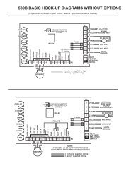
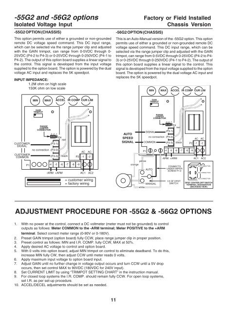
-55G2 and -56G2 options Factory or Field Installed<br />
Isolated Voltage Input<br />
Chassis Version<br />
-55G2 OPTION (CHASSIS)<br />
This option permits use of either a grounded or non-grounded<br />
remote DC voltage speed command. This DC input range,<br />
which can be selected via the range jumper clip and adjusted<br />
with the GAIN trimpot, can range from 0-5VDC through 0-<br />
25VDC (P4-2 to P4-3) or 0-25VDC through 0-250VDC (P4-1 to<br />
P4-2). The output of this option board supplies a linear signal to<br />
the control. This signal is developed from the input voltage<br />
supplied to the option board. The option is powered by the dual<br />
voltage AC input and replaces the 5K speedpot.<br />
INPUT IMPEDANCE:<br />
1.2M ohm on high scale<br />
150K ohm on low scale<br />
-56G2 OPTION (CHASSIS)<br />
This is an Auto-<strong>Manual</strong> version of the -55G2 option. This option<br />
permits use of either a grounded or non-grounded remote DC<br />
voltage speed command. This DC input range, which can be<br />
selected via the range jumper clip and adjusted with the GAIN<br />
trimpot, can range from 0-5VDC through 0-25VDC (P4-2 to P4-<br />
3) or 0-25VDC through 0-250VDC (P4-1 to P4-2). The output of<br />
this option board supplies a linear signal to the control. This<br />
signal is developed from the input voltage supplied to the option<br />
board. The option is powered by the dual voltage AC input and<br />
replaces the 5K speedpot.<br />
MIN MAX ACCEL IR COMP CUR LIM<br />
MIN MAX ACCEL IR COMP CUR LIM<br />
GAIN<br />
TRIMPOT<br />
GAIN<br />
TRIMPOT<br />
RANGE<br />
JUMPER<br />
CONNECTOR<br />
-3 -2 -1<br />
CUSTOMER<br />
SIGNAL<br />
CUSTOMER<br />
COMMON<br />
P1<br />
RANGE<br />
JUMPER<br />
CONNECTOR<br />
-3 -2 -1<br />
P4<br />
red<br />
no connection (P3-2)<br />
-4<br />
(P3-1)<br />
(P3-3)<br />
-5<br />
-6<br />
-ARM +ARM<br />
black<br />
-7<br />
AC AC<br />
P2 -1 -2<br />
-8 -9<br />
AC1 AC2<br />
AUTO<br />
SPEED<br />
SIGNAL<br />
SIGNAL<br />
no connection (P3-2)<br />
COMMON<br />
P1<br />
yellow<br />
orange<br />
AUTO<br />
-4<br />
(P3-1)<br />
(P3-3)<br />
-5<br />
P4<br />
red<br />
-6<br />
-ARM +ARM<br />
black<br />
-7<br />
CONNECTS<br />
UNDER WIPER<br />
SCREW P1-2<br />
AC AC<br />
P2 -1 -2<br />
-8 -9<br />
AC1 AC2<br />
1 6 - NO CONNECTION<br />
2 5 - NO CONNECTION<br />
= customer wiring<br />
= factory wiring<br />
MANUAL<br />
white<br />
1/2 OF DPDT<br />
SWITCH<br />
4 - NO CONNECTION<br />
DPDT CENTER-OFF SWITCH<br />
TERMINAL DESIGNATION<br />
(BACKSIDE VIEW)<br />
ADJUSTMENT PROCEDURE FOR -55G2 & -56G2 OPTIONS<br />
1. With no power at the control, connect a DC voltmeter (meter must not be grounded) to control<br />
outputs as follows: Meter COMMON to the -ARM terminal; Meter POSITIVE to the +ARM<br />
terminal. Select correct meter range (0-90V or 0-180V).<br />
2. Preset GAIN trimpot (option board) fully CCW, place range jumper clip in proper position.<br />
3. Preset control as follows: MIN and I.R. COMP. fully CCW, MAX at 50%.<br />
4. Apply desired AC voltage to control and option board.<br />
5. With 0 volts into option board, adjust MIN trimpot on control to eliminate deadband. To do this,<br />
increase MIN fully CW, then adjust CCW until meter reads 0 volts.<br />
6. Apply maximum input voltage to option board input.<br />
7. Adjust GAIN until no further change in voltage output occurs and turn CCW until a 5V drop<br />
occurs, then set control MAX to 90VDC (180VDC for 240V input).<br />
8. Set CURRENT LIMIT by using “TRIMPOT SETTING CHART” in the instruction manual.<br />
9. For closed loop systems the I.R. COMP. should remain fully CCW. For open loop systems,<br />
set I.R. as per set-up procedure.<br />
10. ACCEL/DECEL adjustments should be set as needed.<br />
11