250G Manual 0102 - Dart Controls
250G Manual 0102 - Dart Controls
250G Manual 0102 - Dart Controls

You also want an ePaper? Increase the reach of your titles
YUMPU automatically turns print PDFs into web optimized ePapers that Google loves.
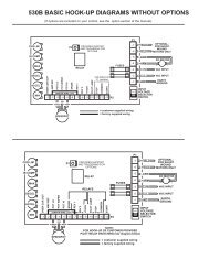
<strong>250G</strong> SERIES CHASSIS HOOK-UP DIAGRAM<br />
Min Max Accel<br />
I.R.<br />
Comp<br />
Cur.<br />
Lim.<br />
Inhibit<br />
Pin<br />
P2<br />
orange<br />
Customer Installed<br />
Speedpot<br />
(factory provides 8"<br />
leads)<br />
white<br />
red<br />
P1<br />
-1 -2 -3<br />
-4 -5 - -6 -7<br />
-8- -9 -10 -11<br />
* Used for shunt wound motors only! No connection is made to these terminals when using permanent magnet motors.<br />
<strong>250G</strong> SERIES ENCLOSED HOOK-UP DIAGRAM<br />
Min Max Accel<br />
I.R.<br />
Comp<br />
Cur.<br />
Lim.<br />
HI (white)<br />
WIPER (red)<br />
LO (orange)<br />
DPST SWITCH<br />
(white<br />
or yellow)<br />
(black)<br />
(white)<br />
(black<br />
or brown)<br />
SPEEDPOT<br />
Inhibit<br />
Pin<br />
P2<br />
INSIDE OF COVER<br />
P1<br />
-1 -2 -3<br />
-4 -5 -6 -7<br />
-8<br />
-9 -10 -11<br />
Pot Lo<br />
Wiper<br />
Pot Hi<br />
-Arm<br />
+Arm<br />
+Field<br />
-Field<br />
AC<br />
AC<br />
Switched AC<br />
Switched AC<br />
Pot Lo<br />
Wiper<br />
Pot Hi<br />
-Arm<br />
+Arm<br />
+Field<br />
-Field<br />
Spare<br />
Spare<br />
AC<br />
AC<br />
field* ac input<br />
motor<br />
armature<br />
chassis<br />
ground<br />
chassis field*<br />
ground<br />
motor<br />
armature ac input<br />
Endplate with holes for 1/2" NPT conduit<br />
* Used for shunt wound motors only! No connection is made to<br />
these terminals when using permanent magnet motors.<br />
5<br />
In the <strong>250G</strong> enclosure kit you will find 2 endplates, a cover<br />
assembly (containing speedpot, DPST switch, gasket and<br />
wiring), and 8 screws. Install both endplates using (4) #5<br />
screws, and the cover assembly, using (4) #6 screws. Before<br />
screwing down cover assembly, route wiring through conduit<br />
holes in endplate by terminal strip.