Automatismo para puerta batiente RotaMatic
Automatismo para puerta batiente RotaMatic
Automatismo para puerta batiente RotaMatic

You also want an ePaper? Increase the reach of your titles
YUMPU automatically turns print PDFs into web optimized ePapers that Google loves.
D<br />
GB<br />
F<br />
NL<br />
I<br />
E<br />
P<br />
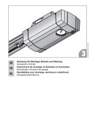
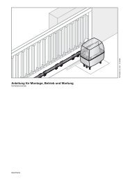
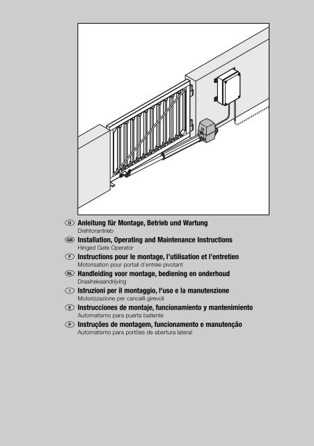
Anleitung für Montage, Betrieb und Wartung<br />
Drehtorantrieb<br />
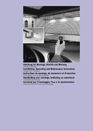
Installation, Operating and Maintenance Instructions<br />
Hinged Gate Operator<br />
Instructions pour le montage, l’utilisation et l’entretien<br />
Motorisation pour portail d’entrée pivotant<br />
Handleiding voor montage, bediening en onderhoud<br />
Draaihekaandrijving<br />
Istruzioni per il montaggio, l'uso e la manutenzione<br />
Motorizzazione per cancelli girevoli<br />
Instrucciones de montaje, funcionamiento y mantenimiento<br />
<strong>Automatismo</strong> <strong>para</strong> <strong>puerta</strong> <strong>batiente</strong><br />
Instruções de montagem, funcionamento e manutenção<br />
<strong>Automatismo</strong> <strong>para</strong> portões de abertura lateral<br />
11.2004 TR10A008-A-A RE 1
250<br />
250<br />
Deutsch................................................................................. 3<br />
English .................................................................................. 6<br />
Français ................................................................................ 9<br />
Nederlands ......................................................................... 12<br />
Italiano ................................................................................ 15<br />
Español ............................................................................... 18<br />
Português ........................................................................... 21<br />
A<br />
180<br />
90<br />
180<br />
90<br />
720<br />
1120<br />
400<br />
B<br />
13 mm<br />
PH 2<br />
3 mm<br />
3 mm<br />
Ø 6,8 mm<br />
Ø 6 mm<br />
Ø 12 mm<br />
2<br />
08.2007 TR10A028-A RE
DEUTSCH<br />
INHALTSVERZEICHNIS<br />
SEITE<br />
A Mitgelieferte Artikel 2<br />
B Benötigtes Werkzeug zur Montage 2<br />
1 WICHTIGE SICHERHEITSINFORMATIONEN 4<br />
1.1 Wichtige Sicherheitsanweisungen 4<br />
1.1.1 Gewährleistung 4<br />
1.1.2 Überprüfung des Tores / der Toranlage 4<br />
1.2 Wichtige Anweisungen für eine sichere Montage 4<br />
1.2.1 Vor der Montage 4<br />
1.2.2 Bei der Durchführung der Montagearbeiten 4<br />
1.2.3 Nach Abschluss der Montage 5<br />
1.3 Warnhinweise 5<br />
1.4 Wartungshinweise 5<br />
1.5 Hinweise zum Bildteil 5<br />
Bildteil 24-39<br />
2 DEFINITIONEN 40<br />
3 VORBEREITUNG DER MONTAGE 40<br />
3.1 Montage des Drehtor-Antriebes 41<br />
3.1.1 Montagegrundsätze für ein lange Lebensdauer<br />
des Antriebes 41<br />
3.1.2 Ermitteln der Anbaumaße 41<br />
3.1.3 Vorzugsbereich 42<br />
3.1.4 Befestigen des Antriebes 42<br />
3.2 Montage der Antriebs-Steuerung 42<br />
3.3 Elektrischer Anschluss 42<br />
3.4 Anschluss von Standardkomponenten 42<br />
3.4.1 Anschluss des Antriebes bei einer 1-flügeligen<br />
Toranlage 42<br />
3.4.2 Anschluss des Antriebes bei einer 2-flügeligen<br />
Toranlage ohne Anschlagleiste 42<br />
3.4.3 Anschluss des Antriebes bei einer 2-flügeligen<br />
Toranlage mit Anschlagleiste 42<br />
3.4.4 Festlegung der Endlagenerfassung 42<br />
3.5 Anschluss von Zusatzkomponenten / Zubehör 43<br />
3.5.1 Anschluss eines externen Funk-Empfängers 43<br />
3.5.2 Anschluss eines externen Tasters für die<br />
Impulssteuerung 43<br />
3.5.3 Anschluss einer Warnleuchte 43<br />
3.5.4 Anschluss von Sicherheitseinrichtungen 43<br />
3.5.5 Anschluss eines Elektroschlosses 43<br />
4 INBETRIEBNAHME DES ANTRIEBES 43<br />
4.1 Allgemeines 43<br />
4.2 Übersicht Einrichtbetrieb 43<br />
4.3 Vorbereitung 43<br />
4.4 Einlernen der Torendlagen 44<br />
4.4.1 Endlagenerfassung "Tor-Zu" durch integrierten<br />
Endschalter 44<br />
4.4.2 Endlagenerfassung durch mechanische<br />
Endanschläge 45<br />
4.4.3 Abschluss des Einrichtbetriebes 45<br />
4.5 Kräfte lernen 45<br />
4.5.1 Lernkraft ändern 45<br />
4.5.2 Langsame Verfahrgeschwindigkeit 46<br />
08.2007 TR10A028-A RE<br />
4.6 Größe des Flügelversatzes 46<br />
4.7 Reversiergrenze 46<br />
4.8 Übersicht und Einstellungen der DIL-Schalter 46<br />
4.8.1 DIL-Schalter 1: 1- oder 2-Flügel-Betrieb 46<br />
4.8.2 DIL-Schalter 2: mit/ohne Flügelversatz 46<br />
4.8.3 DIL-Schalter 3: Flügelwahl/Größe Flügelversatz 46<br />
4.8.4 DIL-Schalter 4: Einrichtbetrieb 46<br />
4.8.5 DIL-Schalter 5: Sicherheitseinrichtung SE 46<br />
4.8.6 DIL-Schalter 6: Funktion der Sicherheitseinrichtung<br />
beim Öffnen 46<br />
4.8.7 DIL-Schalter 7: Funktion der Sicherheitseinrichtung<br />
beim Schließen 46<br />
4.8.8 DIL-Schalter 8: Reversieren in Richtung AUF 46<br />
4.8.9 DIL-Schalter 9 / DIL-Schalter 10 46<br />
4.8.10 DIL-Schalter 11: Sicherheitslichtschranke als<br />
Durchfahrtslichtschranke 47<br />
4.8.11 DIL-Schalter 12: Reversiergrenze/Verfahrgeschwindigkeit<br />
47<br />
5 FUNK-FERNSTEUERUNG 47<br />
5.1 Beschreibung des Handsenders 47<br />
5.2 Integriertes Funkmodul 47<br />
5.3 Einlernen der Handsendertasten für ein<br />
integriertes Funkmodul 47<br />
5.4 Löschen der Daten eines integrierten Funkmoduls 47<br />
5.5 Anschluss eines externen Funk-Empfängers 47<br />
6 WERKS-RESET 48<br />
7 BETRIEB DES DREHTOR-ANTRIEBES 48<br />
7.1 Reversieren bei Kraftbegrenzung 48<br />
7.2 Reversieren bei einer Auffahrt 48<br />
7.3 Reversieren bei einer Zufahrt 48<br />
7.4 Verhalten bei einem Spannungsausfall 48<br />
7.5 Verhalten nach einem Spannungsausfall 48<br />
8 WARTUNG 48<br />
8.1 Betriebs-, Fehler- und Warnmeldungen 48<br />
8.1.1 LED GN 48<br />
8.1.2 LED RT 49<br />
8.2 Fehlerquittierung 49<br />
9 DEMONTAGE 49<br />
10 OPTIONALES ZUBEHÖR,<br />
NICHT IM LIEFERUMFANG ENTHALTEN 49<br />
11 GARANTIEBEDINGUNGEN 49<br />
12 TECHNISCHE DATEN 50<br />
13 ÜBERSICHT DIL-SCHALTER FUNKTIONEN 51<br />
3
DEUTSCH<br />
Sehr geehrter Kunde,<br />
wir freuen uns darüber, dass Sie sich für ein Qualitäts-Produkt<br />
aus unserem Hause entschieden haben. Bewahren Sie diese<br />
Anleitung sorgfältig auf!<br />
Bitte lesen und beachten Sie diese Anleitung, in ihr stehen<br />
wichtige Informationen für den Einbau, den Betrieb und die<br />
korrekte Pflege/Wartung des Drehtor-Antriebes, damit Sie<br />
über viele Jahre Freude an diesem Produkt haben.<br />
Beachten Sie bitte alle unsere Sicherheits- und Warnhinweise,<br />
die mit ACHTUNG bzw. Hinweis besonders gekennzeichnet<br />
sind.<br />
ACHTUNG<br />
Die Montage, Wartung, Re<strong>para</strong>tur und<br />
Demontage des Drehtor-Antriebes soll<br />
durch Sachkundige ausgeführt werden.<br />
Hinweis<br />
Dem Endverbraucher müssen das Prüfbuch und die<br />
Anleitung für die sichere Nutzung und Wartung der<br />
Toranlage zur Verfügung gestellt werden.<br />
1 WICHTIGE SICHERHEITSINFORMATIONEN<br />
ACHTUNG<br />
Eine falsche Montage bzw. eine falsche Handhabung<br />
des Antriebes kann zu ernsthaften<br />
Verletzungen führen. Aus diesem Grund sind<br />
alle Anweisungen zu befolgen, die in dieser<br />
Anleitung enthalten sind!<br />
1.1 Wichtige Sicherheitsanweisungen<br />
Der Drehtor-Antrieb ist ausschließlich für den Betrieb von<br />
leichtgängigen Drehtoren im privaten / nichtgewerblichen<br />
Bereich vorgesehen. Die max. zulässige Torgröße<br />
und das max. Gewicht dürfen nicht überschritten werden.<br />
Der Einsatz an größeren bzw. schwereren Toren<br />
sowie der Einsatz im gewerblichen Bereich ist<br />
nicht zulässig!<br />
Beachten Sie bitte die Herstellerangaben betreffend der<br />
Kombination Tor und Antrieb. Mögliche Gefährdungen<br />
im Sinne der EN 12604, EN 12445 und EN 12453<br />
werden durch die Konstruktion und Montage nach<br />
unseren Vorgaben vermieden. Toranlagen, die sich im<br />
öffentlichen Bereich befinden und nur über eine Schutzeinrichtung,<br />
z.B. Kraftbegrenzung verfügen, dürfen ausschließlich<br />
unter Aufsicht betrieben werden.<br />
1.1.1 Gewährleistung<br />
Wir sind von der Gewährleistung und der Produkthaftung<br />
befreit, wenn ohne unsere vorherige Zustimmung eigene<br />
bauliche Veränderungen vorgenommen oder unsachgemäße<br />
Installationen gegen unsere vorgegebenen<br />
Montagerichtlinien ausgeführt bzw. veranlasst werden.<br />
Weiterhin übernehmen wir keine Verantwortung für den<br />
versehentlichen oder unachtsamen Betrieb des Antriebes<br />
sowie für die unsachgemäße Wartung des Tores, des<br />
Zubehörs und für eine unzulässige Einbauweise des Tores.<br />
Batterien sind ebenfalls von den Gewährleistungsansprüchen<br />
ausgenommen.<br />
Hinweis<br />
Bei Versagen des Drehtor-Antriebes ist unmittelbar ein<br />
Sachkundiger mit der Prüfung / Re<strong>para</strong>tur zu beauftragen.<br />
1.1.2 Überprüfung der Tore / der Toranlage<br />
Die Konstruktion des Antriebes ist nicht für den Betrieb<br />
schwerer Tore, das heißt Tore, die nicht mehr oder nur<br />
schwer von Hand geöffnet oder geschlossen werden<br />
können, ausgelegt. Aus diesem Grund ist es notwendig,<br />
vor der Antriebs-Montage das Tor zu<br />
überprüfen und sicherzustellen, dass es auch<br />
von Hand leicht zu bedienen ist.<br />
Kontrollieren Sie außerdem die gesamte Toranlage<br />
(Gelenke, Lager des Tores und Befestigungsteile) auf<br />
Verschleiß und eventuelle Beschädigungen. Prüfen Sie,<br />
ob Rost, Korrosion oder Risse vorhanden sind. Die<br />
Toranlage ist nicht zu benutzen, wenn Re<strong>para</strong>tur- oder<br />
Einstellarbeiten durchgeführt werden müssen, denn ein<br />
Fehler in der Toranlage oder ein falsch ausgerichtetes<br />
Tor kann ebenfalls zu schweren Verletzungen führen.<br />
Hinweis<br />
Bevor Sie den Antrieb installieren, lassen Sie zu Ihrer<br />
eigenen Sicherheit eventuell erforderliche Re<strong>para</strong>turarbeiten<br />
durch einen qualifizierten Kundendienst ausführen!<br />
1.2 Wichtige Anweisungen für eine sichere Montage<br />
Der Weiterverarbeiter hat darauf zu achten, dass die<br />
nationalen Vorschriften für den Betrieb von elektrischen<br />
Geräten eingehalten werden.<br />
1.2.1 Vor der Montage sind die mechanischen Verriegelungen<br />
des Tores, die nicht für eine Betätigung mit einem Drehtor-<br />
Antrieb benötigt werden, außer Betrieb zu setzen. Hierzu<br />
zählen insbesondere die Verriegelungsmechanismen des<br />
Torschlosses.<br />
1.2.2 Bei der Durchführung der Montagearbeiten sind die<br />
geltenden Vorschriften zur Arbeitssicherheit zu befolgen.<br />
Hinweis<br />
Bei Bohrarbeiten ist der Antrieb abzudecken, weil Bohrstaub<br />
und Späne zu Funktionsstörungen führen können.<br />
4 08.2007 TR10A028-A RE
DEUTSCH<br />
1.2.3 Nach Abschluss der Montage<br />
muss der Errichter der Anlage entsprechend des Geltungsbereiches<br />
die Konformität nach DIN EN 13241-1 erklären.<br />
1.3 Warnhinweise<br />
Achten Sie darauf, dass<br />
- fest installierte Steuerungsgeräte (wie<br />
Taster etc.) in Sichtweite des Tores zu<br />
montieren sind, aber entfernt von sich<br />
bewegenden Teilen und in einer Höhe<br />
von mindestens 1,5 Metern. Sie sind<br />
unbedingt außer Reichweite von<br />
Kindern anzubringen!<br />
- sich im Bewegungsbereich des Tores<br />
keine Personen oder Gegenstände<br />
befinden dürfen.<br />
-Kinder nicht an der Toranlage spielen!<br />
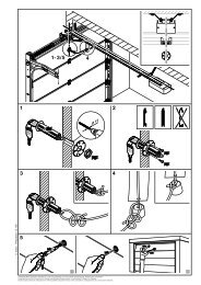
1.5 Hinweise zum Bildteil<br />
Im Bildteil wird die Antriebs-Montage an einem 1-flügeligen<br />
bzw. an einem 2-flügeligen Drehtor dargestellt.<br />
Einige Bilder beinhalten zusätzlich das untenstehende<br />
Symbol mit einem Textverweis. Unter diesen Textverweisen<br />
erhalten Sie wichtige Informationen zur Montage und zum<br />
Betrieb des Drehtor-Antriebes im anschließenden Textteil.<br />
Beispiel:<br />
2.2<br />
= siehe Textteil, Kapitel 2.2<br />
Außerdem wird im Bild- sowie im Textteil an den Stellen,<br />
an denen die DIL-Schalter zum Einstellen der Steuerung<br />
erklärt werden, das folgende Symbol dargestellt.<br />
= Dieses Symbol kennzeichnet<br />
die Werkseinstellung/en der<br />
DIL-Schalter.<br />
- mitgelieferte Warntafeln an gut<br />
sichtbarer Stelle am Tor anbringen<br />
(siehe Bild 2 ).<br />
1.4 Wartungshinweise<br />
Der Drehtor-Antrieb ist wartungsfrei. Zu Ihrer eigenen<br />
Sicherheit empfehlen wir jedoch, die Toranlage nach<br />
Herstellerangaben durch einen Sachkundigen<br />
überprüfen zu lassen.<br />
Hinweis<br />
Alle Sicherheits- und Schutzfunktionen sind monatlich<br />
auf ihre Funktion zu prüfen und falls erforderlich, sind<br />
vorhandene Fehler bzw. Mängel sofort zu beheben.<br />
Die Prüfung und Wartung darf nur von einer sachkundigen<br />
Person durchgeführt werden, wenden Sie sich hierzu<br />
an Ihren Lieferanten. Eine optische Prüfung kann vom<br />
Betreiber durchgeführt werden.<br />
Betreffend notwendiger Re<strong>para</strong>turen wenden Sie sich<br />
an Ihren Lieferanten. Für nicht sach- oder fachgerecht<br />
ausgeführte Re<strong>para</strong>turen übernehmen wir keine<br />
Gewährleistung.<br />
Urheberrechtlich geschützt.<br />
Nachdruck, auch auszugsweise, nur mit unserer Genehmigung.<br />
Änderungen vorbehalten.<br />
08.2007 TR10A028-A RE<br />
5
ENGLISH<br />
CONTENTS<br />
PAGE<br />
A Supplied Items 2<br />
B Required Tools for Installation 2<br />
1 IMPORTANT SAFETY NOTES 7<br />
1.1 Important safety instructions 7<br />
1.1.1 Warranty 7<br />
1.1.2 Checking the gate/gate system 7<br />
1.2 Important instructions for safe installation 7<br />
1.2.1 Prior to installation 7<br />
1.2.2 When carrying out the installation work 7<br />
1.2.3 After installation 8<br />
1.3 Warnings 8<br />
1.4 Maintenance advice 8<br />
1.5 Information on the illustrated section 8<br />
Illustrations 24-39<br />
2 DEFINITIONS 52<br />
3 PREPARATION FOR INSTALLATION 52<br />
3.1 Installing the hinged gate operator 53<br />
3.1.1 Installation fundamentals for a long operator<br />
service life 53<br />
3.1.2 Establishing the fitting dimensions 53<br />
3.1.3 Preferred range 54<br />
3.1.4 Fastening the operator 54<br />
3.2 Installing the operator control 54<br />
3.3 Electrical connection 54<br />
3.4 Connecting standard components 54<br />
3.4.1 Connecting the operator for a single-leaf<br />
gate system 54<br />
3.4.2 Connecting the operator for a double-leaf<br />
gate system without a threshold 54<br />
3.4.3 Connecting the operator for a double-leaf<br />
gate system with a threshold 54<br />
3.4.4 Determining end-of-travel position detection 54<br />
3.5 Connecting additional components/accessories 54<br />
3.5.1 Connecting an external radio receiver 54<br />
3.5.2 Connecting an external button for the impulse<br />
control 55<br />
3.5.3 Connecting a warning light 55<br />
3.5.4 Connecting safety devices 55<br />
3.5.5 Connecting an electro lock 55<br />
4 INITIAL OPERATION OF THE OPERATOR 55<br />
4.1 General 55<br />
4.2 Overview of set-up mode 55<br />
4.3 Pre<strong>para</strong>tion 55<br />
4.4 Learning the gate's end-of-travel positions 56<br />
4.4.1 Detecting the CLOSE end-of-travel position via<br />
the integrated limit switch 56<br />
4.4.2 Detecting the end-of-travel position via mechanical<br />
limit stops 56<br />
4.4.3 Completion of set-up mode 57<br />
4.5 Learning the forces 57<br />
4.5.1 Changing the learned forces 57<br />
4.5.2 Creep speed 57<br />
4.6 Sizes of the leaf offset 57<br />
4.7 Reversing limit 57<br />
4.8 Overview and settings of the DIL switches 58<br />
4.8.1 DIL switch 1: Single or double-leaf operation 58<br />
4.8.2 DIL switch 2: With/without leaf offset 58<br />
4.8.3 DIL switch 3: Leaf selection/size of leaf offset 58<br />
4.8.4 DIL switch 4: Set-up mode 58<br />
4.8.5 DIL switch 5: SE safety device 58<br />
4.8.6 DIL switch 6: Function of the safety device<br />
when opening 58<br />
4.8.7 DIL switch 7: Function of the safety device<br />
when closing 58<br />
4.8.8 DIL switch 8: Reversing to OPEN direction 58<br />
4.8.9 DIL switch 9 / DIL switch 10 58<br />
4.8.10 DIL switch 11: Safety photocell as a through-traffic<br />
photocell 58<br />
4.8.11 DIL switch 12: reversing limit/travel speed 59<br />
5 RADIO REMOTE CONTROL 59<br />
5.1 Hand transmitter description 59<br />
5.2 Integral radio module 59<br />
5.3 Programming the hand transmitter buttons for<br />
the integral radio module 59<br />
5.4 Deleting the data of the internal radio module 59<br />
5.5 Connecting an external radio receiver 59<br />
6 FACTORY RESET 59<br />
7 OPERATING THE HINGED GATE OPERATOR 59<br />
7.1 Reversing with force limit 60<br />
7.2 Reversing while opening 60<br />
7.3 Reversing while closing 60<br />
7.4 Behaviour during a power failure 60<br />
7.5 Behaviour following a power failure 60<br />
8 MAINTENANCE 60<br />
8.1 Operation, error and warning messages 60<br />
8.1.1 LED GN 60<br />
8.1.2 LED RD 60<br />
8.2 Error acknowledgement 61<br />
9 DISMANTLING 61<br />
10 OPTIONAL ACCESSORIES (NOT INCLUDED IN<br />
THE SCOPE OF SUPPLY) 61<br />
11 TERMS AND CONDITIONS OF THE WARRANTY 61<br />
12 TECHNICAL DATA 61<br />
13 OVERVIEW OF DIL SWITCH FUNCTIONS 63<br />
6 08.2007 TR10A028-A RE
ENGLISH<br />
Dear Customer,<br />
Thank you for choosing this quality product from our company.<br />
Keep these instructions in a safe place for later reference!<br />
Please carefully read and follow these instructions. They provide<br />
you with important information on the safe installation, operation<br />
and correct care/maintenance of your hinged gate operator,<br />
thus ensuring that this product will give you satisfaction for<br />
many years to come.<br />
Please observe all our safety notes and warnings, specifically<br />
headed CAUTION or Note .<br />
CAUTION<br />
Installation, maintenance, repair and dismantling<br />
of the hinged gate operator may only be carried<br />
out by specialists.<br />
Note<br />
The inspection log book and instructions for safe handling<br />
and maintenance of the gate system must be placed at the<br />
disposal of the end user.<br />
1 IMPORTANT INFORMATION ON SAFETY<br />
CAUTION<br />
Incorrect installation or handling of the operator<br />
could result in serious injury. For this reason, it<br />
is important to follow all the instructions in this<br />
manual!<br />
1.1 Important safety instructions<br />
The hinged gate operator is designed and intended<br />
exclusively for the operation of smooth-running hinged<br />
gates in the domestic/non-commercial sector.<br />
The maximum permissible gate length and maximum<br />
weight must not be exceeded. It is not permitted to<br />
use the operator on larger or heavier gates or in<br />
the commercial sector!<br />
Please observe the manufacturer's specifications<br />
regarding the gate and operator combination. Possible<br />
hazards as defined in EN 12604, EN 12445 and<br />
EN 12453 are prevented by the design itself and by<br />
carrying out installation in accordance with our guidelines.<br />
Gate systems used by the general public and equipped<br />
with a single protective device, e.g. force limit, may only<br />
be used when monitored.<br />
1.1.1 Warranty<br />
We shall be exempt from our warranty obligations and<br />
product liability in the event that the customer carries out<br />
his own structural alterations or undertakes improper<br />
installation work or arranges for same to be carried out<br />
by others without our prior approval and contrary to the<br />
installation guidelines we have provided. Moreover, we<br />
shall accept no responsibility for the inadvertent or<br />
negligent use of the operator or improper maintenance<br />
of the gate and the accessories nor for a non-authorised<br />
method of installing the gate. Batteries are also not<br />
covered by the warranty.<br />
Note<br />
Should the hinged gate operator fail, a specialist must be<br />
immediately entrusted with its inspection/repair.<br />
1.1.2 Checking the gate/gate system<br />
The design of the operator is not suitable nor intended<br />
for the opening and closing of heavy gates, i.e. gates<br />
that can no longer be opened or closed manually.<br />
Before installing the operator, it is therefore<br />
necessary to check the gate and make sure that<br />
it can also be easily moved by hand.<br />
In addition, check the entire gate system (gate pivots,<br />
bearings and fastenings) for wear and possible damage.<br />
Check for signs of rust, corrosion or fractures. The gate<br />
system may not be used if repair or adjustment work<br />
needs to be carried out. Always remember that a fault<br />
in the gate system or a misaligned gate can also cause<br />
severe injury.<br />
Note<br />
Before installing the operator and in the interests of personal<br />
safety, make sure that any necessary repairs to the gate are<br />
carried out by a qualified service engineer.<br />
1.2 Important instructions for safe installation<br />
Any further processing must ensure that the national<br />
regulations governing the operation of electrical<br />
equipment are complied with<br />
1.2.1 Prior to installation, any mechanical locks not needed<br />
for power operation of the hinged gate, should be<br />
deactivated. This includes in particular any locking<br />
mechanisms connected with the gate lock.<br />
1.2.2 When carrying out the installation work the<br />
applicable regulations regarding working safety must be<br />
complied with.<br />
Note<br />
Always cover the operator before drilling, since drilling dust<br />
and shavings can lead to malfunctions.<br />
08.2007 TR10A028-A RE<br />
7
ENGLISH<br />
1.2.3 After installation<br />
The installer of the gate system must declare conformity<br />
DIN EN 13241-1 in accordance with the scope of<br />
application.<br />
1.3 Warnings<br />
Make sure that<br />
- permanently installed controls (such as<br />
push buttons or similar devices) are<br />
installed within sight of the gate but well<br />
away from any moving parts and at a<br />
height of at least 1.5 metres. It is vital<br />
that they are installed out of the reach<br />
of children!<br />
- neither persons nor objects are located<br />
within the gate's range of travel.<br />
1.5 Information on the illustrated section<br />
The illustrated section shows operator installation on a<br />
single-leaf and double-leaf hinged gate. Some of the<br />
figures also include the symbol shown below together<br />
with a text reference. These references to specific texts<br />
in the ensuing text section provide you with important<br />
information regarding installation and operation of the<br />
hinged gate operator.<br />
Example:<br />
2.2<br />
= see text section, Chapter 2.2<br />
In addition, in both the text section and the illustrated<br />
section at the points where the DIL switches to set the<br />
controls are explained, the following symbol is shown.<br />
- children do not play around with the<br />
gate system!<br />
= This symbol indicates the<br />
factory setting(s) of the DIL<br />
switches.<br />
- the provided warning signs are attached<br />
at an easily visible place on the gate<br />
(see Figure 2 ).<br />
1.4 Maintenance advice<br />
The hinged gate operator is maintenance-free. For your<br />
own safety, however, we recommend having the gate<br />
system checked by a specialist in accordance with<br />
the manufacturer's specifications.<br />
Note<br />
The function of all the safety and protective devices must<br />
be checked once a month and, if necessary, any faults or<br />
defects rectified immediately.<br />
Inspection and maintenance work may only be carried<br />
out by a specialist. In this connection, please contact<br />
your supplier. A visual inspection may be carried out by<br />
the owner.<br />
If repairs become necessary, please contact your supplier.<br />
We would like to point out that any repairs not carried out<br />
properly or with due professionalism shall render the<br />
warranty null and void.<br />
Copyright.<br />
No part of this instruction manual may be reproduced without<br />
our prior permission. Subject to changes.<br />
8 08.2007 TR10A028-A RE
FRANÇAIS<br />
TABLE DES MATIERES<br />
PAGE<br />
A Articles livrés 2<br />
B Outils nécessaires au montage 2<br />
1 INFORMATIONS ESSENTIELLES A LA<br />
SECURITE 10<br />
1.1 Consignes essentielles à la sécurité 10<br />
1.1.1 Garantie 10<br />
1.1.2 Vérification du portail/de l'installation de portail 10<br />
1.2 Consignes essentielles à la fiabilité du montage 10<br />
1.2.1 Avant le montage 10<br />
1.2.2 Lors de l'exécution des travaux de montage 10<br />
1.2.3 Au terme du montage 11<br />
1.3 Avertissements 11<br />
1.4 Remarques relatives à l'entretien 11<br />
1.5 Remarques relatives aux illustrations 11<br />
Illustrations 24-39<br />
2 DEFINITIONS 64<br />
3 PREPARATION DU MONTAGE 64<br />
3.1 Montage de la motorisation pour portail pivotant 65<br />
3.1.1 Normes de montage relatives à la longévité de la<br />
motorisation 65<br />
3.1.2 Détermination des dimensions de montage 65<br />
3.1.3 Zone préférentielle 66<br />
3.1.4 Fixation de la motorisation 66<br />
3.2 Montage de la commande de motorisation 66<br />
3.3 Raccordement électrique 66<br />
3.4 Raccordement de composants standards 66<br />
3.4.1 Raccordement de la motorisation pour installation<br />
de portail à 1 vantail 66<br />
3.4.2 Raccordement de la motorisation pour installation<br />
de portail à 2 vantaux sans listel de butée 66<br />
3.4.3 Raccordement de la motorisation pour installation<br />
de portail à 2 vantaux avec listel de butée 67<br />
3.4.4 Détermination de la détection des positions finales 67<br />
3.5 Raccordement de composants/d'accessoires<br />
additionnels 67<br />
3.5.1 Raccordement d'un récepteur radio externe 67<br />
3.5.2 Raccordement d'un bouton-poussoir externe pour<br />
la commande par impulsion 67<br />
3.5.3 Raccordement d'une lampe d'avertissement 67<br />
3.5.4 Raccordement de dispositifs de sécurité 67<br />
3.5.5 Raccordement d'un verrou électrique 67<br />
4 MISE EN SERVICE DE LA MOTORISATION 67<br />
4.1 Généralités 68<br />
4.2 Aperçu du service de réglage 68<br />
4.3 Pré<strong>para</strong>tion 68<br />
4.4 Apprentissage des positions finales de portail 68<br />
4.4.1 Détection de la position finale « portail fermé » par<br />
interrupteur de fin de course intégré 68<br />
4.4.2 Détection des positions finales par butées<br />
mécaniques 69<br />
4.4.3 Fin du service de réglage 69<br />
4.5 Apprentissage des forces 69<br />
08.2007 TR10A028-A RE<br />
4.5.1 Modification de la force d'apprentissage 70<br />
4.5.2 Vitesse lente de déplacement 70<br />
4.6 Dimension du décalage de vantail 70<br />
4.7 Limite d'inversion 70<br />
4.8 Aperçu et réglages des commutateurs DIP 70<br />
4.8.1 Commutateur DIP 1 : service à 1 vantail ou<br />
2 vantaux 70<br />
4.8.2 Commutateur DIP 2 : avec/sans décalage de<br />
vantail 71<br />
4.8.3 Commutateur DIP 3 : sélection du vantail/<br />
dimension du décalage de vantail 71<br />
4.8.4 Commutateur DIP 4 : service de réglage 71<br />
4.8.5 Commutateur DIP 5 : dispositif de sécurité SE 71<br />
4.8.6 Commutateur DIP 6 : fonction du dispositif de<br />
sécurité lors de l'ouverture 71<br />
4.8.7 Commutateur DIP 7 : fonction du dispositif de<br />
sécurité lors de la fermeture 71<br />
4.8.8 Commutateur DIP 8 : inversion dans le sens<br />
OUVERTURE 71<br />
4.8.9 Commutateur DIP 9 / Commutateur DIP 10 71<br />
4.8.10 Commutateur DIP 11 : cellule photoélectrique<br />
de sécurité en tant que cellule photoélectrique<br />
de passage 71<br />
4.8.11 Commutateur DIP 12 : limite d'inversion/vitesse de<br />
déplacement 71<br />
5 TELECOMMANDE RADIO 71<br />
5.1 Description de l'émetteur 71<br />
5.2 Module radio intégré 72<br />
5.3 Apprentissage des touches de l'émetteur pour le<br />
module radio intégré 72<br />
5.4 Effacement des données d'un module radio intégré 72<br />
5.5 Raccordement d'un récepteur radio externe 72<br />
6 REMISE A L'ETAT DE LIVRAISON 72<br />
7 SERVICE DE LA MOTORISATION POUR<br />
PORTAIL PIVOTANT 72<br />
7.1 Inversion en cas de limitation d'effort 73<br />
7.2 Inversion pendant une ouverture 73<br />
7.3 Inversion pendant une fermeture 73<br />
7.4 Comportement lors d'une panne de secteur 73<br />
7.5 Comportement après une panne de secteur 73<br />
8 ENTRETIEN 73<br />
8.1 Messages de service, d'erreur et d'avertissement 73<br />
8.1.1 DEL GN 73<br />
8.1.2 DEL RT 73<br />
8.2 Confirmation d'erreur 74<br />
9 DEMONTAGE 74<br />
10 ACCESSOIRES OPTIONNELS, NON COMPRIS<br />
DANS LE VOLUME DE LIVRAISON 74<br />
11 CONDITIONS DE GARANTIE 74<br />
12 SPECIFICATIONS TECHNIQUES 74<br />
13 APERCU DES FONCTIONS DES<br />
COMMUTATEURS DIP 76<br />
9
FRANÇAIS<br />
Chères clientes, chers clients,<br />
Nous sommes heureux que vous ayez choisi l’un des produits<br />
de qualité que nous proposons. Veuillez conserver soigneusement<br />
les présentes instructions !<br />
Veuillez également les lire et les respecter. Ces instructions<br />
comportent des informations essentielles au montage, au service<br />
et à la maintenance/l'entretien correct(e) de la motorisation pour<br />
portail pivotant. Ce produit vous donnera ainsi entière satisfaction<br />
pendant de nombreuses années.<br />
Veuillez respecter toutes nos consignes de sécurité et<br />
d'avertissement, spécifiées tout particulièrement par ATTENTION<br />
ou Remarque .<br />
ATTENTION<br />
Le montage, l'entretien, la ré<strong>para</strong>tion et le<br />
démontage de la motorisation pour portail<br />
pivotant doivent être exécutés par un expert en<br />
la matière.<br />
Remarque<br />
Le carnet d'essai et les instructions garantissant la fiabilité<br />
d'utilisation et d'entretien de l'installation de portail doivent<br />
être mis à la disposition de l'utilisateur final.<br />
1 INFORMATIONS ESSENTIELLES A LA SECURITÉ<br />
ATTENTION<br />
Le montage ou la manipulation incorrects de la<br />
motorisation peuvent provoquer de graves<br />
blessures. Veuillez donc respecter<br />
scrupuleusement toutes les consignes<br />
mentionnées dans la présente notice !<br />
1.1 Consignes essentielles à la sécurité<br />
La motorisation pour portail pivotant est exclusivement<br />
destinée au service de portails pivotants à manœuvrabilité<br />
aisée, dans le cadre d'un usage privé/non<br />
professionnel. Les limites maximales dimensionnelles et<br />
pondérales du portail ne doivent être en aucun cas<br />
dépassées. Son utilisation pour des portails dont les<br />
dimensions et/ou le poids excèdent les maxima<br />
autorisés, ainsi que son usage dans un cadre<br />
professionnel, sont proscrits !<br />
Veuillez respecter les spécifications du fabricant relatives<br />
à la combinaison portail - motorisation. La construction<br />
et le montage, conformes à nos directives, permettent<br />
d'éviter les dangers potentiels, mentionnés dans les<br />
euronormes EN 12604, EN 12445, et EN 12453. Les<br />
installations de portail qui se trouvent dans les lieux<br />
publics et ne sont équipées que d'un seul dispositif<br />
protecteur, tel que p. ex. un limiteur d'effort, ne peuvent<br />
être utilisées que sous supervision.<br />
1.1.1 Garantie<br />
Nous déclinons toute responsabilité et n'appliquons<br />
aucune garantie produit dans le cas où, sans notre<br />
accord préalable, vous effectueriez des modifications<br />
structurelles ou procèderiez à des installations<br />
inappropriées, contraires aux directives de montage que<br />
nous avons fixées. En outre, nous ne saurions être tenus<br />
responsables en cas de service accidentel ou impropre<br />
de la motorisation, d'un mauvais entretien du portail et<br />
des accessoires, ainsi qu'en cas de montage non<br />
autorisé du portail. Les batteries sont également exclues<br />
de la garantie.<br />
Remarque<br />
En cas de défaillance de la motorisation pour portail<br />
pivotant, il convient de faire immédiatement appel à un<br />
expert pour le contrôle/la ré<strong>para</strong>tion.<br />
1.1.2 Vérification du portail/de l'installation de portail<br />
La construction de la motorisation n'est pas conçue<br />
pour la manœuvre de portails lourds, c.-à-d. pour les<br />
portails qu’il est devenu impossible ou difficile d’ouvrir et<br />
de fermer à la main. Avant d'effectuer le montage de<br />
la motorisation du portail, il est par conséquent<br />
impératif de procéder à son contrôle et de vérifier<br />
aussi qu’il se manœuvre facilement à la main.<br />
En outre, contrôlez l'absence d'usure et<br />
d'endommagements sur l'intégralité de l'installation de<br />
portail (charnières, paliers du portail et pièces de fixation).<br />
Vérifiez l'absence de rouille, de corrosion ou de fissures.<br />
L'utilisation d'une installation de portail requérant des<br />
travaux de ré<strong>para</strong>tion ou de réglage est interdite. La<br />
présence d'une erreur dans l'installation de portail ou le<br />
mauvais alignement du portail peuvent également<br />
occasionner de graves blessures.<br />
Remarque<br />
Avant d'installer la motorisation, faites impérativement réaliser,<br />
pour votre propre sécurité, les éventuels travaux de ré<strong>para</strong>tion<br />
par un service après-vente qualifié !<br />
1.2 Consignes essentielles à la fiabilité du montage<br />
L'installateur devra veiller à ce que les prescriptions<br />
nationales relatives au service des appareils électriques<br />
soient respectées.<br />
1.2.1 Avant le montage, les verrous mécaniques du portail,<br />
qui ne sont pas nécessaires pour la manœuvre avec une<br />
motorisation pour portail pivotant, doivent être mis hors<br />
service. Il s'agit tout particulièrement des mécanismes de<br />
verrouillage du verrou du portail.<br />
1.2.2 Lors de l'exécution des travaux de montage, les<br />
prescriptions en vigueur, relatives à la sécurité au travail,<br />
doivent être respectées.<br />
Remarque<br />
Lors des travaux de perçage, il convient de couvrir la<br />
motorisation, afin que la poussière de perçage et les copeaux<br />
ne puissent pas générer de défaillances fonctionnelles.<br />
10 08.2007 TR10A028-A RE
FRANÇAIS<br />
1.2.3 Au terme du montage<br />
L'installateur est tenu de procéder à une déclaration de<br />
conformité de l'installation, selon l'euronorme DIN<br />
EN 13241-1, conformément au domaine d'application.<br />
1.3 Avertissements<br />
Veillez à ce que<br />
1.5 Remarques relatives aux illustrations<br />
Les illustrations présentent le montage d'une motorisation<br />
sur un portail pivotant à 1 vantail ou à 2 vantaux. Certaines<br />
illustrations comportent, en outre, le pictogramme<br />
ci-dessous, accompagné d'un renvoi au texte. Les textes<br />
correspondants, référencés par ces renvois, contiennent<br />
des informations essentielles au montage et au service de<br />
la motorisation pour portail pivotant.<br />
-les appareils de commande fixes (tels<br />
que les boutons-poussoirs, etc.) soient<br />
montés en vue du portail, mais à l'écart<br />
des pièces mobiles et à une hauteur d'au<br />
moins 1,5 m. Il est impératif qu'ils soient<br />
installés hors de portée des enfants !<br />
Exemple :<br />
2.2<br />
= voir texte, chapitre 2.2<br />
- aucun objet ou aucun personne ne se<br />
trouve dans la plage de déplacement du<br />
portail.<br />
Le pictogramme suivant figure, en outre, dans les<br />
illustrations et dans le texte, aux emplacements qui<br />
fournissent des explications sur les commutateurs DIP<br />
pour le réglage de la commande.<br />
- les enfants ne jouent pas au niveau de<br />
l'installation de portail !<br />
= ce pictogramme caractérise<br />
le/les <strong>para</strong>mètre(s) d'usine<br />
des commutateurs DIP.<br />
- les panneaux d'avertissement fournis<br />
soient placés à des emplacements bien<br />
visibles sur le portail (voir figure 2 ).<br />
1.4 Remarques relatives à l'entretien<br />
La motorisation pour portail pivotant ne nécessite aucun<br />
entretien. Pour votre propre sécurité, nous vous<br />
recommandons cependant de faire contrôler l'installation<br />
de portail par un expert, conformément aux<br />
spécifications du fabricant.<br />
Remarque<br />
La fonctionnalité de toutes les fonctions de sécurité et de<br />
protection doit être contrôlée tous les mois. D'éventuelles<br />
erreurs et imperfections doivent être, le cas échéant,<br />
éliminées immédiatement.<br />
Seul un expert est habilité à procéder au contrôle et à<br />
l'entretien. Contactez à cet effet votre fournisseur.<br />
L'exploitant peut cependant procéder au contrôle visuel.<br />
Si des ré<strong>para</strong>tions s'imposent, contactez votre fournisseur.<br />
Nous déclinons toute responsabilité en cas de ré<strong>para</strong>tions<br />
mal ou non effectuées.<br />
Droits d'auteur réservés.<br />
Reproduction, même partielle, uniquement avec notre<br />
autorisation. Sous réserve de modifications.<br />
08.2007 TR10A028-A RE<br />
11
NEDERLANDS<br />
INHOUDSOPGAVE<br />
BLZ<br />
A Meegeleverde artikelen 2<br />
B Gereedschap nodig voor de montage 2<br />
1 BELANGRIJKE VEILIGHEIDSINFORMATIE 13<br />
1.1 Belangrijke veiligheidsvoorschriften 13<br />
1.1.1 Garantie 13<br />
1.1.2 Controle van het draaihek / de draaihekinstallatie 13<br />
1.2 Belangrijke voorschriften voor een veilige montage 13<br />
1.2.1 Voor de montage 13<br />
1.2.2 Tijdens de montagewerkzaamheden 13<br />
1.2.3 Na de montage 14<br />
1.3 Waarschuwingen 14<br />
1.4 Onderhoudsvoorschriften 14<br />
1.5 Richtlijnen bij de illustraties 14<br />
Illustraties 24-39<br />
2 DEFINITIES 77<br />
3 VOORBEREIDING VAN DE MONTAGE 77<br />
3.1 Montage van de draaihekaandrijving 78<br />
3.1.1 Basisprincipes bij de montage voor een lange<br />
levensduur van de aandrijving 78<br />
3.1.2 Bepalen van de inbouwmaten 78<br />
3.1.3 Voorkeurbereik 79<br />
3.1.4 Aandrijving bevestigen 79<br />
3.2 Montage van de aandrijvingsbesturing 79<br />
3.3 Elektrische aansluiting 79<br />
3.4 Standaardcomponenten aansluiten 79<br />
3.4.1 Aandrijving voor 1-vleugelige draaihekinstallatie<br />
aansluiten 79<br />
3.4.2 Aandrijving voor 2-vleugelige draaihekinstallatie<br />
zonder aanslaglijst aansluiten 79<br />
3.4.3 Aandrijving voor 2-vleugelige draaihekinstallatie<br />
met aanslaglijst aansluiten 79<br />
3.4.4 Registratie van de eindpositie 80<br />
3.5 Extra componenten/toebehoren aansluiten 80<br />
3.5.1 Externe radio-ontvanger aansluiten 80<br />
3.5.2 Externe schakelaar voor impulsbesturing aansluiten 80<br />
3.5.3 Waarschuwingslicht aansluiten 80<br />
3.5.4 Veiligheidsvoorzieningen aansluiten 80<br />
3.5.5 Elektrisch slot aansluiten 80<br />
4 INBEDRIJFSTELLING VAN DE AANDRIJVING 80<br />
4.1 Algemeen 80<br />
4.2 Overzicht van installatie 80<br />
4.3 Voorbereiding 81<br />
4.4 Draaihekeindposities programmeren 81<br />
4.4.1 Registratie eindpositie "draaihek-dicht" door<br />
geïntegreerde eindschakelaar 81<br />
4.4.2 Registratie eindpositie door mechanische<br />
eindaanslagen 82<br />
4.4.3 Installatie afsluiten 82<br />
4.5 Krachten leren kennen 82<br />
4.5.1 Aanleerkracht wijzigen 83<br />
4.5.2 Trage loopsnelheid 83<br />
4.6 Omvang van de vleugelbeweging 83<br />
4.7 Terugkeergrens 83<br />
4.8 Overzicht en instellingen van de DIL-schakelaars 83<br />
4.8.1 DIL-schakelaar 1: 1- of 2-vleugelige uitvoering 83<br />
4.8.2 DIL-schakelaar 2: met/zonder vleugelbeweging 83<br />
4.8.3 DIL-schakelaar 3: vleugelkeuze/omvang<br />
vleugelbeweging 83<br />
4.8.4 DIL-schakelaar 4: installatie 83<br />
4.8.5 DIL-schakelaar 5: veiligheidsvoorziening SE 83<br />
4.8.6 DIL-schakelaar 6: functie van de<br />
veiligheidsvoorziening bij het openen 83<br />
4.8.7 DIL-schakelaar 7: functie van de<br />
veiligheidsvoorziening bij het sluiten 83<br />
4.8.8 DIL-schakelaar 8: terugloop in de richting OPEN 84<br />
4.8.9 DIL-schakelaar 9 / DIL-schakelaar 10 84<br />
4.8.10 DIL-schakelaar 11: veiligheidsfotocel als doorrijfotocel 84<br />
4.8.11 DIL-schakelaar 12: terugkeergrens/loopsnelheid 84<br />
5 AFSTANDSBEDIENING 84<br />
5.1 Beschrijving van de handzender 84<br />
5.2 Geïntegreerde radiomodule 84<br />
5.3 Programmeren van de handzendertoetsen voor een<br />
geïntegreerde radiomodule 84<br />
5.4 Wissen van de gegevens van een geïntegreerde<br />
radiomodule 85<br />
5.5 Externe radio-ontvanger aansluiten 85<br />
6 FABRIEKSRESET 85<br />
7 WERKING VAN DE DRAAIHEKAANDRIJVING 85<br />
7.1 Terugloop bij krachtbegrenzing 85<br />
7.2 Terugloop bij het openen 85<br />
7.3 Terugloop bij het sluiten 85<br />
7.4 Wat te doen bij spanningsuitval 85<br />
7.5 Wat te doen na spanningsuitval 86<br />
8 ONDERHOUD 86<br />
8.1 Werkings-, fout- en waarschuwingsmeldingen 86<br />
8.1.1 LED GN 86<br />
8.1.2 LED RT 86<br />
8.2 Reacties op fouten 86<br />
9 DEMONTAGE 86<br />
10 OPTIONELE TOEBEHOREN, NIET IN DE<br />
LEVERINGSOMVANG INBEGREPEN 87<br />
11 GARANTIEVOORWAARDEN 87<br />
12 TECHNISCHE GEGEVENS 87<br />
13 OVERZICHT FUNCTIES VAN DE<br />
DIL-SCHAKELAARS 89<br />
12 08.2007 TR10A028-A RE
NEDERLANDS<br />
Geachte klant,<br />
Wij danken u dat u heeft gekozen voor een kwaliteitsproduct uit<br />
ons huis. Bewaar deze handleiding zorgvuldig!<br />
Lees deze handleiding aandachtig. Ze geeft u belangrijke<br />
informatie over de montage, de werking en het juiste onderhoud<br />
van de draaihekaandrijving, zodat u jarenlang veel plezier zult<br />
beleven aan dit product.<br />
Neem alle veiligheids- en waarschuwingsaanwijzingen in acht.<br />
Ze worden extra verduidelijkt door de woorden ATTENTIE of<br />
Opmerking .<br />
ATTENTIE<br />
Montage, onderhoud, herstelling en demontage<br />
van de draaihekaandrijving moeten door een<br />
vakman uitgevoerd worden.<br />
Opmerking<br />
Het controleboek en de handleiding voor veilig gebruik<br />
en onderhoud van de draaihekinstallatie moeten aan<br />
de eindgebruiker ter beschikking gesteld worden.<br />
1 BELANGRIJKE VEILIGHEIDSINFORMATIE<br />
ATTENTIE<br />
Een foutieve montage of gebruik van de<br />
aandrijving kan tot ernstige letsels leiden.<br />
Daarom moet u alle instructies in deze<br />
handleiding nauwgezet navolgen!<br />
1.1 Belangrijke veiligheidsvoorschriften<br />
De draaihekaandrijving is uitsluitend bestemd voor de<br />
bediening van licht lopende draaihekken voor privé-/<br />
niet-commerciële doeleinden. De maximaal toegelaten<br />
grootte van het draaihek en het maximaal toegelaten<br />
gewicht mogen niet overschreden worden.<br />
Het gebruik bij grotere of zwaardere draaihekken<br />
en het gebruik voor commerciële doeleinden is<br />
verboden!<br />
Let op de aanwijzingen van de fabrikant met betrekking<br />
tot de combinatie van draaihek en aandrijving. Mogelijke<br />
gevaren in het kader van EN 12604, EN 12445 en<br />
EN 12453 worden vermeden door onze aanwijzingen<br />
te volgen bij de constructie en montage.<br />
Draaihekinstallaties op openbare plaatsen met slechts<br />
één beveiligingsuitrusting, bijvoorbeeld krachtbegrenzing,<br />
mogen enkel onder toezicht bediend worden.<br />
1.1.1 Garantie<br />
Wij zijn vrijgesteld van garantie en productaansprakelijkheid<br />
indien, zonder onze voorafgaande<br />
toestemming, eigen constructiewijzigingen of<br />
ondeskundige installaties in tegenstrijd met onze<br />
montagerichtlijnen worden aangebracht. Verder zijn we<br />
niet verantwoordelijk voor verkeerd of achteloos gebruik<br />
van de aandrijving, voor ondeskundig onderhoud van<br />
het draaihek en toebehoren en voor ontoelaatbare<br />
draaihekconstructies. De garantiebepalingen zijn ook<br />
niet van toepassing op batterijen.<br />
Opmerking<br />
Wanneer de draaihekaandrijving faalt, moet onmiddellijk<br />
de hulp van een vakman voor controle / herstelling<br />
ingeroepen worden.<br />
1.1.2 Controle van het draaihek / de draaihekinstallatie<br />
De aandrijving werd niet ontworpen voor de bediening<br />
van zware draaihekken, d.w.z. draaihekken die niet meer<br />
of zeer moeilijk met de hand geopend of gesloten kunnen<br />
worden. Daarom is het noodzakelijk dat u voor de<br />
montage van de aandrijving het draaihek controleert<br />
en zeker bent dat het ook met de hand gemakkelijk<br />
te bedienen is.<br />
Controleer bovendien de volledige draaihekinstallatie<br />
(scharnieren, lagers en bevestigingspunten) op slijtage<br />
en eventuele beschadigingen. Ga na of er roest, corrosie<br />
of scheuren zijn. Gebruik de draaihekinstallatie niet indien<br />
ze hersteld of bijgeregeld moet worden omdat fouten<br />
in de draaihekinstallatie of een slecht afgesteld draaihek<br />
eveneens tot zware letsels kunnen leiden.<br />
Opmerking<br />
Voordat u de aandrijving installeert, laat u voor uw eigen<br />
veiligheid eventueel noodzakelijke herstellingen uitvoeren<br />
door een gekwalificeerde servicedienst!<br />
1.2 Belangrijke voorschriften voor een veilige montage<br />
De gebruiker moet erop letten dat de nationale<br />
voorschriften voor het gebruik van elektrische toestellen<br />
gerespecteerd worden.<br />
1.2.1 Voor de montage moeten de mechanische<br />
vergrendelingen van het draaihek buiten gebruik gesteld<br />
worden omdat ze bij de bediening van een draaihekaandrijving<br />
niet nodig zijn. Het gaat hier vooral over<br />
de vergrendelingsmechanismen van het draaihekslot.<br />
1.2.2 Tijdens de montagewerkzaamheden moeten de<br />
geldende veiligheidsvoorschriften worden gevolgd.<br />
Opmerking<br />
Bij boorwerkzaamheden moet de aandrijving afgedekt<br />
worden omdat boorstof en spaanders kunnen leiden tot<br />
functiestoringen.<br />
08.2007 TR10A028-A RE<br />
13
NEDERLANDS<br />
1.2.3 Na de montage<br />
moet de installateur in overeenstemming met het<br />
geldigheidsbereik de installatie conform DIN EN 13241-1<br />
verklaren.<br />
1.3 Waarschuwingen<br />
Let erop dat<br />
1.5 Richtlijnen bij de illustraties<br />
In de illustraties wordt de montage van de aandrijving aan<br />
een 1-vleugelig of 2-vleugelig draaihek voorgesteld. Enkele<br />
illustraties bevatten bovendien het onderstaande symbool<br />
met een verwijzing naar de tekst. in deze tekstverwijzingen<br />
kunt u belangrijke informatie over de montage en de<br />
werking van de draaihekaandrijving in het aansluitende<br />
tekstgedeelte vinden.<br />
- vaste bedieningselementen (zoals<br />
schakelaars, enz.) in het zicht van het<br />
draaihek gemonteerd moeten worden,<br />
maar weg van de bewegende delen en<br />
op een hoogte van minstens 1,5 meter.<br />
Zij moeten absoluut buiten het bereik<br />
van kinderen worden aangebracht!<br />
Voorbeeld:<br />
2.2<br />
= zie tekstgedeelte, hoofdstuk<br />
2.2<br />
- zich geen personen of voorwerpen in<br />
het bewegingsbereik van het draaihek<br />
bevinden.<br />
- kinderen niet bij de draaihekinstallatie<br />
spelen!<br />
Bovendien wordt het volgende symbool zowel in het<br />
illustratie- als in het tekstgedeelte weergegeven op die<br />
plaatsen, waar de DIL-schakelaars voor het instellen van<br />
de bediening uitgelegd worden.<br />
= dit symbool duidt de<br />
fabrieksinstelling(en) van<br />
de DIL-schakelaars aan.<br />
- meegeleverde waarschuwingsborden<br />
op goed zichtbare plaatsen op het<br />
draaihek aangebracht worden<br />
(zie afbeelding 2 ).<br />
1.4 Onderhoudsvoorschriften<br />
De draaihekaandrijving is onderhoudsvrij. Voor uw eigen<br />
veiligheid raden wij u echter aan, de draaihekinstallatie<br />
volgens de instructies van de fabrikant door een<br />
vakman te laten controleren.<br />
Opmerking<br />
Alle veiligheids- en beveiligingsfuncties moeten maandelijks<br />
op hun werking gecontroleerd worden en indien nodig moeten<br />
fouten of gebreken onmiddellijk opgelost worden.<br />
De controle en het onderhoud mogen enkel door een<br />
vakman uitgevoerd worden. Neem hiervoor contact op<br />
met uw leverancier. De gebruiker kan een optische<br />
controle uitvoeren.<br />
Neem contact op met uw leverancier voor noodzakelijke<br />
herstellingen. Wij bieden geen garantie voor niet-vakkundig<br />
uitgevoerde herstellingen.<br />
Door de auteurwet beschermd.<br />
Gehele of gedeeltelijke nadruk is zonder onze<br />
toestemming niet toegestaan.<br />
Constructiewijzigingen voorbehouden.<br />
14 08.2007 TR10A028-A RE
ITALIANO<br />
INDICE<br />
PAGINA<br />
A Articoli forniti 2<br />
B Attrezzi necessari per il montaggio 2<br />
1 INFORMAZIONI IMPORTANTI PER LA<br />
SICUREZZA 16<br />
1.1 Informazioni importanti per la sicurezza 16<br />
1.1.1 Garanzia 16<br />
1.1.2 Controllo del cancello / del sistema di chiusura 16<br />
1.2 Istruzioni importanti per un montaggio sicuro 16<br />
1.2.1 Prima del montaggio 16<br />
1.2.2 Durante i lavori di montaggio 16<br />
1.2.3 Al termine del montaggio 17<br />
1.3 Avvertenze 17<br />
1.4 Avvertenze per la manutenzione 17<br />
1.5 Note relative alla parte illustrata 17<br />
Parte illustrata 24-39<br />
2 DEFINIZIONI 90<br />
3 PREPARATIVI PER IL MONTAGGIO 90<br />
3.1 Montaggio della motorizzazione 91<br />
3.1.1 Principi di montaggio per una lunga durata della<br />
motorizzazione 91<br />
3.1.2 Rilevamento delle misure di posizionamento 91<br />
3.1.3 Area preferita 92<br />
3.1.4 Fissaggio della motorizzazione 92<br />
3.2 Montaggio della centralina di comando della<br />
motorizzazione 92<br />
3.3 Collegamento elettrico 92<br />
3.4 Collegamento di componenti standard 92<br />
3.4.1 Collegamento della motorizzazione per un cancello<br />
ad 1 battente 92<br />
3.4.2 Collegamento della motorizzazione per un cancello<br />
a 2 battenti senza listello di battuta 92<br />
3.4.3 Collegamento della motorizzazione per un cancello<br />
a 2 battenti con listello di battuta 92<br />
3.4.4 Definizione del rilevamento delle posizioni di fine corsa 92<br />
3.5 Collegamento di componenti supplementari /<br />
accessori 93<br />
3.5.1 Collegamento di un ricevitore radio esterno 93<br />
3.5.2 Collegamento di un pulsante esterno per il comando<br />
ad impulsi 93<br />
3.5.3 Collegamento di un lampeggiante 93<br />
3.5.4 Collegamento di dispositivi di sicurezza 93<br />
3.5.5 Collegamento di una serratura elettrica 93<br />
4 MESSA IN FUNZIONE DELLA<br />
MOTORIZZAZIONE 93<br />
4.1 Generalità 93<br />
4.2 Panoramica della modalità di regolazione 93<br />
4.3 Pre<strong>para</strong>tivi 94<br />
4.4 Apprendimento delle posizioni di fine corsa 94<br />
4.4.1 Rilevamento della posizione di "Chiusura" tramite<br />
finecorsa integrato 94<br />
4.4.2 Rilevamento delle posizioni di fine corsa tramite<br />
battute di fine corsa meccaniche 95<br />
08.2007 TR10A028-A RE<br />
4.4.3 Termine della modalità di regolazione 95<br />
4.5 Apprendimento delle forze 95<br />
4.5.1 Modifica della forza di apprendimento 96<br />
4.5.2 Velocità di corsa lenta 96<br />
4.6 Lunghezza del ritardo di apertura/chiusura<br />
di un battente 96<br />
4.7 Limite di inversione marcia 96<br />
4.8 Panoramica e impostazioni degli interruttori DIL 96<br />
4.8.1 Interruttore DIL 1: funzionamento a 1 o 2 battenti 96<br />
4.8.2 Interruttore DIL 2: con/senza ritardo di un battente 96<br />
4.8.3 Interruttore DIL 3: scelta battente/intervallo di<br />
ritardo di un battente 96<br />
4.8.4 Interruttore DIL 4: modalità di regolazione 96<br />
4.8.5 Interruttore DIL 5: dispositivo di sicurezza SE 96<br />
4.8.6 Interruttore DIL 6: funzione del dispositivo di<br />
sicurezza in apertura 96<br />
4.8.7 Interruttore DIL 7: funzione del dispositivo di<br />
sicurezza in chiusura 97<br />
4.8.8 Interruttore DIL 8: inversione nella direzione di<br />
apertura 97<br />
4.8.9 Interruttore DIL 9 / interruttore DIL 10 97<br />
4.8.10 Interruttore DIL 11: fotocellula di sicurezza come<br />
fotocellula per il transito 97<br />
4.8.11 Interruttore DIL 12: limite di inversione<br />
marcia/velocità di corsa 97<br />
5 RADIOCOMANDO A DISTANZA 97<br />
5.1 Descrizione del telecomando 97<br />
5.2 Radiomodulo integrato 97<br />
5.3 Apprendimento dei pulsanti del telecomando<br />
su un radiomodulo integrato 98<br />
5.4 Cancellazione dei dati di un radiomodulo integrato 98<br />
5.5 Collegamento di un ricevitore radio esterno 98<br />
6 RIPRISTINO DELLE IMPOSTAZIONI DI<br />
FABBRICA 98<br />
7 FUNZIONAMENTO DELLA MOTORIZZAZIONE<br />
PER CANCELLI A BATTENTE 98<br />
7.1 Inversione di marcia in caso di limitazione di sforzo 98<br />
7.2 Inversione di marcia durante un'apertura 98<br />
7.3 Inversione di marcia durante una chiusura 98<br />
7.4 Comportamento in caso di black-out 99<br />
7.5 Comportamento dopo un black-out 99<br />
8 MANUTENZIONE 99<br />
8.1 Segnalazione di funzionamento, errore e allarme 99<br />
8.1.1 LED GN 99<br />
8.1.2 LED RT 99<br />
8.2 Conferma errori 99<br />
9 SMONTAGGIO 99<br />
10 ACCESSORI OPZIONALI, NON<br />
COMPRESI NELLA FORNITURA 100<br />
11 CONDIZIONI DI GARANZIA 100<br />
12 DATI TECNICI 100<br />
13 PANORAMICA FUNZIONI DEGLI<br />
INTERRUTTORI DIL 102<br />
15
ITALIANO<br />
Gentile cliente,<br />
siamo lieti che Lei abbia scelto un prodotto di qualità di nostra<br />
produzione. La preghiamo di conservare queste istruzioni con<br />
cura e di leggere attentamente le seguenti avvertenze, che Le<br />
forniranno importanti informazioni sull'installazione, sull'uso e<br />
sulla corretta manutenzione della motorizzazione per cancelli a<br />
battente. Siamo certi che questo prodotto Le procurerà grande<br />
soddisfazione per molti anni.<br />
La preghiamo di rispettare tutte le avvertenze per la sicurezza e<br />
le segnalazioni di pericolo, contrassegnate rispettivamente dalle<br />
diciture ATTENZIONE e Avvertenza .<br />
ATTENZIONE<br />
Si consiglia di far eseguire il montaggio, la<br />
manutenzione, la ri<strong>para</strong>zione e lo smontaggio<br />
della motorizzazione per cancelli a battente da<br />
uno specialista.<br />
Avvertenza<br />
L'utente finale deve disporre del libretto di controllo e delle<br />
istruzioni per l'utilizzo e la manutenzione sicuri del sistema<br />
di chiusura.<br />
1 INFORMAZIONI IMPORTANTI PER LA SICUREZZA<br />
ATTENZIONE<br />
Un montaggio e/o un uso non corretto della<br />
motorizzazione possono causare gravi lesioni<br />
fisiche. Pertanto La preghiamo di seguire tutte<br />
le avvertenze contenute in questo manuale!<br />
1.1 Avvertenze importanti per la sicurezza<br />
La motorizzazione per cancelli a battente è prevista<br />
esclusivamente per il funzionamento di cancelli a<br />
battente facilmente manovrabili ad uso privato / non<br />
industriale. Le dimensioni max. ammissibili e il peso<br />
max. del cancello non devono essere superati.<br />
L'impiego su cancelli più grandi o più pesanti e<br />
l'impiego industriale non sono consentiti!<br />
La preghiamo di seguire le indicazioni del costruttore<br />
relative alla combinazione di cancello e motorizzazione.<br />
La costruzione e il montaggio eseguiti nel rispetto delle<br />
nostre prescrizioni escludono eventuali pericoli ai sensi<br />
delle norme EN 12604, EN 12445 e EN 12453. Sistemi<br />
di chiusura installati in un ambiente pubblico e dotati di<br />
un solo dispositivo di sicurezza, p. es. limitatore di sforzo,<br />
possono essere manovrati solo sotto sorveglianza.<br />
1.1.1 Garanzia<br />
La nostra ditta è sollevata dalla garanzia e dalla<br />
responsabilità per il prodotto qualora il cliente effettui<br />
modifiche costruttive senza previo consenso da parte<br />
nostra oppure esegua/faccia eseguire lavori d'installazione<br />
inadeguati e non conformi alle nostre istruzioni di<br />
montaggio. Inoltre decliniamo ogni responsabilità in caso<br />
di uso non corretto della motorizzazione o di<br />
manutenzione inadeguata del cancello e degli accessori<br />
nonché in caso di tipo di montaggio non consentito del<br />
cancello. Anche le batterie sono escluse dalla garanzia.<br />
Avvertenza<br />
In caso di guasto della motorizzazione per cancelli a battente,<br />
incaricare immediatamente uno specialista del controllo / della<br />
ri<strong>para</strong>zione.<br />
1.1.2 Controllo del cancello / del sistema di chiusura<br />
Questo tipo di motorizzazione non è adatto all'impiego<br />
su cancelli pesanti, vale a dire chiusure che non possano<br />
più essere manovrate manualmente, o solo con molta<br />
difficoltà. Per questi motivi, prima del montaggio<br />
della motorizzazione, è indispensabile controllare<br />
il cancello ed assicurarsi che possa essere<br />
manovrato manualmente.<br />
Controllare inoltre che sull'intero sistema di chiusura<br />
(snodi, supporti del cancello ed elementi di fissaggio) non<br />
siano presenti punti usurati ed eventuali difetti. Verificare<br />
anche che non ci siano tracce di ruggine, corrosione<br />
o incrinature. Non utilizzare il sistema di chiusura quando<br />
sono necessari interventi di ri<strong>para</strong>zione o di regolazione:<br />
anche un suo difetto o errato allineamento possono<br />
provocare gravi lesioni.<br />
Avvertenza<br />
Prima di installare la motorizzazione, far eseguire, per<br />
sicurezza, i lavori di ri<strong>para</strong>zione eventualmente necessari<br />
da un Servizio di Assistenza Clienti qualificato!<br />
1.2 Istruzioni importanti per un montaggio sicuro<br />
L'installatore deve rispettare le norme nazionali per il<br />
funzionamento di apparecchiature elettriche.<br />
1.2.1 Prima del montaggio dovranno essere messi fuori<br />
servizio tutti i dispositivi di bloccaggio meccanico del<br />
cancello non utilizzati nella manovra motorizzata.<br />
Particolare attenzione va dedicata ai meccanismi di<br />
blocco della serratura.<br />
1.2.2 Durante i lavori di montaggio rispettare le norme<br />
vigenti per la sicurezza sul lavoro.<br />
Avvertenza<br />
Durante i lavori di trapanatura coprire la motorizzazione,<br />
perché la polvere e i trucioli potrebbero causare anomalie<br />
di funzionamento.<br />
16 08.2007 TR10A028-A RE
ITALIANO<br />
1.2.3 Al termine del montaggio<br />
La ditta che esegue l'installazione deve dichiararne la<br />
conformità ai sensi della norma UNI EN 13241-1.<br />
1.3 Avvertenze<br />
Achten Sie darauf, dass<br />
- gli elementi di comando ad installazione<br />
fissa (quali pulsanti ecc.) vengano installati<br />
in modo da essere ben visibili dal<br />
cancello, ma sufficientemente lontani da<br />
elementi mobili e ad un'altezza di almeno<br />
1,5 metri. Devono essere installati fuori<br />
dalla portata dei bambini!<br />
- nella zona di manovra del cancello non<br />
si trovino né persone né oggetti.<br />
- non vi siano bambini che giocano vicino<br />
al sistema di chiusura!<br />
1.5 Note relative alla parte illustrata<br />
Nella parte illustrata è raffigurata l'installazione della<br />
motorizzazione su un cancello ad 1 battente o a 2<br />
battenti. Alcune illustrazioni sono inoltre accompagnate<br />
dal simbolo sottostante, insieme ad un rimando alla<br />
parte delle istruzioni. Questo rimando Le fornirà<br />
importanti informazioni, relative al montaggio e all'uso<br />
della motorizzazione per cancelli a battente contenute<br />
nella parte delle istruzioni.<br />
Esempio:<br />
2.2<br />
= vedere la parte delle<br />
istruzioni, capitolo 2.2<br />
Nella parte illustrata e in quella delle istruzioni, nei punti in<br />
cui vengono descritti gli interruttori DIL per la regolazione<br />
del comando, è rappresentato il seguente simbolo.<br />
= questo simbolo rappresenta<br />
la/le impostazione/i di<br />
fabbrica degli interruttori DIL.<br />
- le targhette di segnalazione in<br />
dotazione siano applicate sul cancello<br />
in un punto ben visibile (vedere Fig. 2 ).<br />
1.4 Avvertenze per la manutenzione<br />
La motorizzazione per cancelli a battente non richiede<br />
manutenzione. Per la Sua sicurezza Le consigliamo,<br />
tuttavia, di far controllare il sistema di chiusura da uno<br />
specialista secondo le indicazioni del costruttore.<br />
Avvertenza<br />
Far controllare ogni mese il funzionamento di tutti i dispositivi<br />
di sicurezza e di protezione e, se necessario, eliminare<br />
immediatamente le anomalie o i difetti presenti.<br />
Il controllo e la manutenzione devono essere eseguiti solo<br />
da una persona qualificata. La preghiamo di rivolgersi al<br />
Suo fornitore. Il controllo visivo può essere eseguito<br />
dall'utilizzatore.<br />
Per quanto riguarda le eventuali ri<strong>para</strong>zioni rivolgersi al<br />
proprio fornitore. Non prestiamo alcuna garanzia per<br />
ri<strong>para</strong>zioni effettuate non correttamente né a regola d'arte.<br />
Diritti d'autore riservati.<br />
Riproduzione, anche solo parziale, previa nostra autorizzazione.<br />
La Ditta si riserva la facoltà di apportare modifiche al prodotto.<br />
08.2007 TR10A028-A RE<br />
17
ESPAÑOL<br />
ÍNDICE<br />
PÁGINA<br />
A Artículos suministrados 2<br />
B Herramientas necesarias <strong>para</strong> el montaje 2<br />
1 INFORMACIÓN IMPORTANTE PARA LA<br />
SEGURIDAD 19<br />
1.1 Indicaciones de seguridad importantes 19<br />
1.1.1 Garantía 19<br />
1.1.2 Comprobación de la <strong>puerta</strong>/de la instalación de<br />
<strong>puerta</strong> 19<br />
1.2 Indicaciones importantes <strong>para</strong> un montaje seguro 19<br />
1.2.1 Antes del montaje 19<br />
1.2.2 Durante los trabajos de montaje 19<br />
1.2.3 Después de finalizar el montaje 20<br />
1.3 Advertencias 20<br />
1.4 Indicaciones de mantenimiento 20<br />
1.5 Indicaciones sobre las ilustraciones 20<br />
Ilustraciones 24-39<br />
2 DEFINICIONES 103<br />
3 PREPARACIÓN DEL MONTAJE 103<br />
3.1 Montaje del automatismo <strong>para</strong> <strong>puerta</strong> <strong>batiente</strong> 104<br />
3.1.1 Principios de montaje <strong>para</strong> una larga vida<br />
útil del automatismo 104<br />
3.1.2 Determinación de las medidas de montaje 104<br />
3.1.3 Entorno de funcionamiento recomendado 105<br />
3.1.4 Fijación del automatismo 105<br />
3.2 Montaje del cuadro de maniobra del automatismo 105<br />
3.3 Conexión eléctrica 105<br />
3.4 Conexión de componentes estándar 105<br />
3.4.1 Conexión del automatismo en una instalación<br />
de <strong>puerta</strong> de 1 hoja 105<br />
3.4.2 Conexión del automatismo en una instalación de<br />
<strong>puerta</strong> de dos hojas sin listón de tope 105<br />
3.4.3 Conexión del automatismo en una instalación de<br />
<strong>puerta</strong> de dos hojas con listón de tope 106<br />
3.4.4 Determinación del registro de las posiciones finales 106<br />
3.5 Conexión de componentes adicionales/accesorios 106<br />
3.5.1 Conexión de un receptor de radio frecuencia externo 106<br />
3.5.2 Conexión de un pulsador externo <strong>para</strong> el control<br />
por impulso 106<br />
3.5.3 Conexión de una luz de aviso 106<br />
3.5.4 Conexión de dispositivos de seguridad 106<br />
3.5.5 Conexión de una cerradura eléctrica 106<br />
4 PUESTA EN MARCHA DEL AUTOMATISMO 106<br />
4.1 Generalidades 107<br />
4.2 Resumen de configuración 107<br />
4.3 Pre<strong>para</strong>ción 107<br />
4.4 Aprendizaje de las posiciones finales de la <strong>puerta</strong> 107<br />
4.4.1 Registro de la posición final "Puerta cerrada"<br />
mediante interruptor final integrado 107<br />
4.4.2 Registro de la posición final "Puerta cerrada"<br />
mediante topes finales mecánicos 108<br />
4.4.3 Conclusión de la configuración 108<br />
4.5 Aprendizaje de fuerzas 108<br />
4.5.1 Modificación de la fuerza de aprendizaje 109<br />
4.5.2 Velocidad de recorrido lenta 109<br />
4.6 Tamaño del desplazamiento de las hojas 109<br />
4.7 Límite <strong>para</strong> inversión del movimiento 109<br />
4.8 Resumen y ajustes de los interruptores DIL 110<br />
4.8.1 Interruptor DIL 1: Funcionamiento de 1 ó 2 hojas 110<br />
4.8.2 Interruptor DIL 2: con/sin desplazamiento de las<br />
hojas 110<br />
4.8.3 Interruptor DIL 3: Selección de las hojas/tamaño<br />
del desplazamiento de las hojas 110<br />
4.8.4 Interruptor DIL 4: Configuración 110<br />
4.8.5 Interruptor DIL 5: Dispositivo de seguridad SE 110<br />
4.8.6 Interruptor DIL 6: Función del dispositivo de<br />
seguridad al abrir 110<br />
4.8.7 Interruptor DIL 7: Función del dispositivo de<br />
seguridad al cerrar 110<br />
4.8.8 Interruptor DIL 8: Inversión en dirección ABRIR 110<br />
4.8.9 Interruptor DIL 9 / interruptor DIL 10: 110<br />
4.8.10 Interruptor DIL 11: Célula fotoeléctrica de<br />
seguridad como célula fotoeléctrica de paso 110<br />
4.8.11 Interruptor DIL 12: Límite <strong>para</strong> inversión/<br />
velocidad de recorrido 111<br />
5 MANDO A DISTANCIA POR RADIO<br />
FRECUENCIA 111<br />
5.1 Descripción del emisor manual 111<br />
5.2 Módulo de radio frecuencia integrado 111<br />
5.3 Aprendizaje de los pulsadores de los emisores<br />
manuales <strong>para</strong> el módulo de radio frecuencia<br />
integrado 111<br />
5.4 Borrar los datos del módulo de radio frecuencia<br />
interno 111<br />
5.5 Conexión de un receptor de radio frecuencia externo 111<br />
6 RESTABLECIMIENTO DE LOS AJUSTES<br />
DE FÁBRICA 111<br />
7 FUNCIONAMIENTO DEL AUTOMATISMO<br />
PARA PUERTA BATIENTE 111<br />
7.1 Inversión en caso de limitación de fuerza 112<br />
7.2 Inversión en movimiento de apertura 112<br />
7.3 Inversión en movimiento de cierre 112<br />
7.4 Comportamiento durante un fallo de corriente 112<br />
7.5 Comportamiento después de un fallo de corriente 112<br />
8 MANTENIMIENTO 112<br />
8.1 Avisos de funcionamiento, fallo y advertencia 112<br />
8.1.1 LED GN 112<br />
8.1.2 LED RT 112<br />
8.2 Confirmación de fallo 113<br />
9 DESMONTAJE 113<br />
10 ACCESORIOS OPCIONALES NO INCLUIDOS<br />
EN EL SUMINISTRO 113<br />
11 CONDICIONES DE GARANTÍA 113<br />
12 DATOS TÉCNICOS 114<br />
13 ESQUEMA DE LAS FUNCIONES<br />
DE LOS INTERRUPTORES DIL 115<br />
18 08.2007 TR10A028-A RE
ESPAÑOL<br />
Estimado cliente:<br />
Nos complace que se haya decidido por un producto de calidad<br />
de nuestra empresa. ¡Guarde estas instrucciones<br />
cuidadosamente!<br />
Lea y siga estas instrucciones que contienen información<br />
importante <strong>para</strong> la instalación, funcionamiento y correcto cuidado/<br />
mantenimiento del automatismo <strong>para</strong> <strong>puerta</strong> <strong>batiente</strong>, <strong>para</strong> que<br />
pueda disfrutar este producto durante muchos años.<br />
Siga todas nuestras indicaciones de seguridad y de advertencia<br />
señaladas con ATENCIÓN y Nota .<br />
ATENCIÓN<br />
Los trabajos de montaje, mantenimiento,<br />
re<strong>para</strong>ción y desmontaje del automatismo <strong>para</strong><br />
<strong>puerta</strong> <strong>batiente</strong> deben ser realizados por expertos.<br />
Nota<br />
Se deben poner a disposición del usuario final el libro de<br />
control y entrega, así como las instrucciones <strong>para</strong> el uso<br />
y mantenimiento seguros de la instalación de la <strong>puerta</strong>.<br />
1 INFORMACIÓN IMPORTANTE PARA LA SEGURIDAD<br />
ATENCIÓN<br />
Un montaje o manejo incorrectos del automatismo<br />
pueden ocasionar lesiones graves. Por este<br />
motivo se deben seguir todas las indicaciones<br />
contenidas en este manual de instrucciones.<br />
1.1 Indicaciones de seguridad importantes<br />
El automatismo <strong>para</strong> <strong>puerta</strong> <strong>batiente</strong> está previsto<br />
exclusivamente <strong>para</strong> el accionamiento de <strong>puerta</strong>s<br />
<strong>batiente</strong>s de funcionamiento suave en el ámbito privado/<br />
no industrial. No se deben sobrepasar la medida<br />
máxima de la <strong>puerta</strong> ni el peso máximo permisibles.<br />
No está permitido su empleo en <strong>puerta</strong>s más<br />
grandes o más pesadas, ni en el ámbito industrial.<br />
Tenga en cuenta las indicaciones del fabricante respecto<br />
a la combinación de la <strong>puerta</strong> y el automatismo.<br />
Siguiendo nuestras especificaciones <strong>para</strong> la construcción<br />
y el montaje, se evitan posibles riesgos según las normas<br />
EN 12604, EN 12445 y EN 12453. Las instalaciones de<br />
<strong>puerta</strong>s empleadas en lugares públicos que sólo disponen<br />
de un dispositivo protector, p. ej. limitación de fuerza,<br />
únicamente pueden funcionar bajo supervisión.<br />
1.1.1 Garantía<br />
Estamos exentos de garantía y responsabilidad por<br />
el producto en caso de que se hagan modificaciones<br />
constructivas propias sin nuestro previo consentimiento<br />
o se realicen o encarguen realizar instalaciones incorrectas<br />
que contravengan las aquí indicadas directivas de<br />
montaje. Tampoco asumimos responsabilidad alguna<br />
por el funcionamiento por descuido o inadvertido del<br />
automatismo, ni por el mantenimiento incorrecto de la<br />
<strong>puerta</strong>, de los accesorios y por un tipo de montaje no<br />
permitido de la <strong>puerta</strong>. Las pilas también quedan<br />
excluidas de los derechos de garantía.<br />
Nota<br />
En caso de fallo del automatismo <strong>para</strong> <strong>puerta</strong> <strong>batiente</strong><br />
debe encargarse su revisión/re<strong>para</strong>ción inmediatamente<br />
a un experto.<br />
1.1.2 Comprobación de la <strong>puerta</strong> / de la instalación de<br />
la <strong>puerta</strong><br />
La construcción del automatismo no está diseñada <strong>para</strong><br />
funcionar con <strong>puerta</strong>s pesadas, es decir, <strong>puerta</strong>s que no<br />
se pueden abrir o cerrar manualmente o sólo con gran<br />
dificultad. Por este motivo, antes de montar el<br />
automatismo, es necesario comprobar la <strong>puerta</strong><br />
y asegurarse de que también se puede manejar<br />
con facilidad manualmente.<br />
Asimismo debe controlarse en toda la instalación de la<br />
<strong>puerta</strong> (articulaciones, apoyos de la <strong>puerta</strong> y elementos de<br />
fijación) si presenta desgaste u otros daños. Compruebe<br />
si hay óxido, corrosión o grietas. Durante la realización de<br />
trabajos de re<strong>para</strong>ción o de ajuste, no se debe utilizar la<br />
instalación de la <strong>puerta</strong>, ya que un error en la instalación<br />
de la <strong>puerta</strong> o una <strong>puerta</strong> ajustada incorrectamente<br />
también puede ocasionar lesiones graves.<br />
Nota<br />
Por su propia seguridad, encargue los trabajos de re<strong>para</strong>ción<br />
necesarios a un servicio técnico cualificado antes de instalar<br />
el automatismo.<br />
1.2 Indicaciones importantes <strong>para</strong> un montaje seguro<br />
El instalador debe prestar atención a que se sigan las<br />
normas nacionales <strong>para</strong> el manejo de a<strong>para</strong>tos eléctricos.<br />
1.2.1 Antes del montaje deben ponerse fuera de servicio los<br />
bloqueos mecánicos de la <strong>puerta</strong> que no se necesitan<br />
<strong>para</strong> un accionamiento mediante un automatismo <strong>para</strong><br />
<strong>puerta</strong> <strong>batiente</strong>. Esto se refiere en especial a los<br />
mecanismos de bloqueo de la cerradura de la <strong>puerta</strong>.<br />
1.2.2 Durante la realización de los trabajos de montaje<br />
deben seguirse las normas vigentes en materia de<br />
seguridad laboral.<br />
Nota<br />
Durante los trabajos de perforación, debe cubrirse el<br />
automatismo, ya que el polvo de la perforación y las virutas<br />
pueden causar fallos de funcionamiento.<br />
08.2007 TR10A028-A RE<br />
19
ESPAÑOL<br />
1.2.3 Después de finalizar el montaje<br />
El instalador debe realizar la declaración de conformidad<br />
según la norma DIN EN 13241-1 <strong>para</strong> el correspondiente<br />
ámbito de empleo.<br />
1.3 Advertencias<br />
Preste atención a<br />
- que los a<strong>para</strong>tos de control fijos (como<br />
pulsadores, etc.) deben montarse en<br />
un lugar visible desde la <strong>puerta</strong>, pero<br />
alejados de las partes móviles y a una<br />
altura mínima de 1,5 metros.<br />
¡Es imprescindible situarlos fuera del<br />
alcance de los niños!<br />
- que en la zona de movimiento de la<br />
<strong>puerta</strong> no se encuentre ninguna persona<br />
ni ningún objeto.<br />
- que no jueguen niños cerca de la<br />
instalación de la <strong>puerta</strong>.<br />
1.5 Indicaciones sobre las ilustraciones<br />
En las ilustraciones se describe el montaje del<br />
automatismo en una <strong>puerta</strong> <strong>batiente</strong> de 1 ó 2 hojas.<br />
Algunas ilustraciones contienen además el símbolo<br />
representado abajo con una remisión al texto. Con estas<br />
remisiones al texto obtendrá información importante<br />
<strong>para</strong> el montaje y el funcionamiento del automatismo<br />
<strong>para</strong> <strong>puerta</strong> <strong>batiente</strong> en la parte del texto indicada.<br />
Ejemplo:<br />
2.2<br />
= véase texto del capítulo 2.2<br />
Las ilustraciones y partes del texto que explican los<br />
interruptores DIL <strong>para</strong> el ajuste del cuadro de maniobra<br />
están señaladas además con el símbolo siguiente.<br />
=Este símbolo indica el/los<br />
ajuste/s de fábrica de los<br />
interruptores DIL.<br />
- que las placas de advertencia<br />
suministradas sean instaladas en<br />
un lugar bien visible de la <strong>puerta</strong><br />
(véase ilustración 2 ).<br />
1.4 Indicaciones de mantenimiento<br />
El automatismo <strong>para</strong> <strong>puerta</strong> <strong>batiente</strong> no requiere<br />
mantenimiento. No obstante, <strong>para</strong> su propia seguridad,<br />
recomendamos hacer revisar la instalación de la<br />
<strong>puerta</strong> una vez al año por un experto según las<br />
especificaciones del fabricante.<br />
Nota<br />
Todas las funciones de seguridad y protección deben<br />
comprobarse mensualmente y, en caso necesario, deben<br />
solucionarse inmediatamente los fallos o deficiencias<br />
existentes.<br />
La comprobación y el mantenimiento sólo deben ser<br />
realizados por una persona experta; diríjase <strong>para</strong> ello<br />
a su proveedor. El propietario puede realizar una<br />
comprobación visual.<br />
Diríjase a su proveedor respecto a las re<strong>para</strong>ciones<br />
necesarias. No asumimos la responsabilidad por<br />
re<strong>para</strong>ciones realizadas de forma incorrecta o inexperta.<br />
Copyright.<br />
Prohibida la reproducción íntegra o parcial<br />
sin nuestra autorización.<br />
Reservado el derecho a modificaciones.<br />
20 08.2007 TR10A028-A RE
PORTUGUÊS<br />
ÍNDICE<br />
PÁGINA<br />
A Artigos fornecidos 2<br />
B Ferramentas necessárias <strong>para</strong> a montagem do<br />
automatismo 2<br />
1 INFORMAÇÕES IMPORTANTES DE<br />
SEGURANÇA 22<br />
1.1 Instruções importantes de segurança 22<br />
1.1.1 Garantia 22<br />
1.1.2 Controlo do portão / dispositivo do portão 22<br />
1.2 Instruções importantes <strong>para</strong> uma montagem segura 22<br />
1.2.1 Antes da montagem 22<br />
1.2.2 Durante a realização de trabalhos de montagem 22<br />
1.2.3 Após conclusão da montagem 23<br />
1.3 Instruções de prevenção 23<br />
1.4 Instruções de manutenção 23<br />
1.5 Instruções sobre as ilustrações 23<br />
Ilustrações 24-39<br />
2 DEFINIÇÕES 116<br />
3 PREPARAÇÃO DA MONTAGEM 116<br />
3.1 Montagem do automatismo <strong>para</strong> portões de batente 117<br />
3.1.1 Regras básicas de montagem <strong>para</strong> uma longa<br />
durabilidade do automatismo 117<br />
3.1.2 Apuramento das medidas de construção 117<br />
3.1.3 Área de preferência 118<br />
3.1.4 Fixação do automatismo 118<br />
3.2 Montagem do comando do automatismo 118<br />
3.3 Ligação eléctrica 118<br />
3.4 Ligação de componentes normalizados 118<br />
3.4.1 Ligação de automatismo em dispositivo de<br />
portão de 1 batente 118<br />
3.4.2 Ligação de automatismo em dispositivo de<br />
portão sem régua de batente 118<br />
3.4.3 Ligação de automatismo em dispositivo de<br />
portão com régua de batente 118<br />
3.4.4 Detecção da posição final 119<br />
3.5 Ligação de componentes adicionais/acessórios 119<br />
3.5.1 Ligação de um receptor de radiofrequência externo 119<br />
3.5.2 Ligação de um interruptor <strong>para</strong> o comando de<br />
impulsos 119<br />
3.5.3 Ligação de uma lâmpada de sinalização 119<br />
3.5.4 Ligação de dispositivos de segurança 119<br />
3.5.5 Ligação de uma fechadura eléctrica 119<br />
4 COLOCAÇÃO EM FUNCIONAMENTO<br />
DO AUTOMATISTMO 119<br />
4.1 Generalidades 119<br />
4.2 Resumo do funcionamento de ajuste 120<br />
4.3 Pre<strong>para</strong>ção 120<br />
4.4 Programação das posições finais do portão 120<br />
4.4.1 Detecção da posições finais "Portão fechado"<br />
através de interruptor final 120<br />
4.4.2 Detecção da posições finais através de<br />
batente final mecânico 121<br />
4.4.3 Conclusão do funcionamento de ajuste 121<br />
08.2007 TR10A028-A RE<br />
4.5 Programar forças 121<br />
4.5.1 Alterar a força programada 122<br />
4.5.2 Velocidade de deslocação lenta 122<br />
4.6 Tamanho da deslocação de batente 122<br />
4.7 Limite de retorno 122<br />
4.8 Resumo de ajustes dos interruptores DIL 122<br />
4.8.1 Interruptor DIL 1: Funcionamento <strong>para</strong> 1 ou 2<br />
batentes 122<br />
4.8.2 Interruptor DIL 2: com/sem deslocação de batente 122<br />
4.8.3 Interruptor DIL 3: Seleccão de batente/Tamanho<br />
deslocação de batente 123<br />
4.8.4 Interruptor DIL 4: Funcionamento de ajuste 123<br />
4.8.5 Interruptor DIL 5: Dispositivo de segurança SE 123<br />
4.8.6 Interruptor DIL 6: Função de dispositivo de<br />
segurança ao abrir 123<br />
4.8.7 Interruptor DIL 7: Função de dispositivo de<br />
segurança ao fechar 123<br />
4.8.8 Interruptor DIL 8: Retornar em sentido "Portão<br />
aberto" 123<br />
4.8.9 Interruptor DIL 9 / Interruptor DIL 10 123<br />
4.8.10 Interruptor DIL 11: Barreira luminosa de segurança<br />
como barreira luminosa de passagem 123<br />
4.8.11 Interruptor DIL 12: Limite de retorno/Velocidade<br />
de deslocação 123<br />
5 TELECOMANDO POR RADIOFREQUÊNCIA 123<br />
5.1 Descrição do telecomando 123<br />
5.2 Módulo de radiofrequência integrado 123<br />
5.3 Programação das teclas do telecomando <strong>para</strong> um<br />
módulo de radiofrequência integrado 124<br />
5.4 Anular os dados de um módulo de radiofrequência<br />
integrado 124<br />
5.5 Ligação de um receptor de radiofrequência externo 124<br />
6 RESET DE FÁBRICA 124<br />
7 FUNCIONAMENTO DO AUTOMATISMO<br />
PARA PORTÕES DE BATENTE 124<br />
7.1 Retorno em limitação de força 124<br />
7.2 Retorno ao abrir 124<br />
7.3 Retorno ao fechar 125<br />
7.4 Medidas a tomar aquando de cortes<br />
de energia eléctrica 125<br />
7.5 Medidas a tomar após cortes de energia eléctrica 125<br />
8 MANUTENÇÃO 125<br />
8.1 Comunicações de funcionamento, erro e aviso 125<br />
8.1.1 LED GN 125<br />
8.1.2 LED RT 125<br />
8.2 Regularização de erros 126<br />
9 DESMONTAGEM 126<br />
10 ACESSÓRIOS OPCIONAIS, QUE NÃO ESTÃO<br />
INCLUÍDOS NO VOLUME DE ENTREGA 126<br />
11 CONDIÇÕES DE GARANTIA 126<br />
12 DADOS TÉCNICOS 126<br />
13 RESUMO DAS FUNÇÕES DOS<br />
INTERRUPTORES DIL 128<br />
21
PORTUGUÊS<br />
Exmo. Cliente,<br />
Agradecemos ter optado por um dos nossos produtos de<br />
qualidade. Guarde cuidadosamente estas instruções!<br />
Por favor leia e cumpra estas instruções, que contêm<br />
informações importantes relativas à montagem, ao funcionamento<br />
e à conservação/manutenção do automatismo <strong>para</strong> portões de<br />
batente <strong>para</strong> que, deste modo, fique satisfeito com este produto<br />
durante muito tempo.<br />
Por favor cumpra todas as nossas instruções de segurança<br />
e prevenção, sobretudo aquelas que estão assinaladas com<br />
ATENÇÃO ou Instrução .<br />
ATENÇÃO<br />
A montagem, manutenção, re<strong>para</strong>ção e<br />
desmontagem do automatismo <strong>para</strong> portões<br />
de batente terá de ser realizada por pessoas<br />
qualificadas.<br />
Instrução<br />
Ao utilizador final terá de ser disponibilizado o livro de<br />
ensaio e as instruções <strong>para</strong> a utilização e manutenção<br />
segura do dispositivo do portão.<br />
1 INSTRUÇÕES IMPORTANTES DE SEGURANÇA<br />
ATENÇÃO<br />
A montagem incorrecta ou o manuseio incorrecto<br />
do automatismo pode levar a danos graves. Por<br />
essa razão, cumpra todas as instruções que se<br />
encontram neste manual de instruções!<br />
1.1 Instruções importantes de segurança<br />
O automatismo <strong>para</strong> portões de batente tem como<br />
finalidade exclusiva o funcionamento de portões de<br />
batente de marcha suave no âmbito doméstico/ não<br />
industrial. A dimensão e o peso máx. permitidos do<br />
portão não podem ser excedidos. Não é permitida<br />
a aplicação em portões maiores ou portões mais<br />
pesados nem a aplicação no sector industrial!<br />
Por favor cumpra as instruções do fabricante no que<br />
diz respeito à combinação do portão e do automatismo.<br />
Possíveis perigos são evitados, segundo as normas<br />
europeias EN 12604, EN 12445 e EN 12453, se a<br />
construção e a montagem forem realizadas, de acordo<br />
com as nossas instruções. Os dispositivos de portão,<br />
que se encontrem na área pública e só disponham de<br />
um dispositivo de protecção, por exemplo, limitação<br />
de força só podem ser operados exclusivamente sob<br />
vigilância.<br />
1.1.1 Garantia<br />
Sem a nossa autorização prévia, fica excluída a garantia<br />
e a responsabilidade, no que diz respeito ao produto, se<br />
forem feitas alterações de construção ou forem<br />
providenciadas ou feitas instalações indevidas, que vão<br />
contra as nossas instruções de montagem. Para além<br />
disso, não assumimos qualquer responsabilidade no que<br />
respeita o funcionamento descuidado do automatismo ou<br />
a manutenção incorrecta do portão, dos acessórios e do<br />
modo de montagem inadmissível do portão. As pilhas<br />
ficam igualmente excluídas das pretensões de garantia.<br />
Instrução<br />
Aquando de falhas no automatismo <strong>para</strong> portões de batente<br />
terá de se contactar, de imediato, uma pessoa qualificada<br />
<strong>para</strong> realizar o ensaio / a re<strong>para</strong>ção.<br />
1.1.2 Controlo do portão / dispositivo do portão<br />
A construção do automatismo não se adequa ao<br />
funcionamento de portões de marcha pesada, isto é,<br />
portões que já não abram ou fechem ou abram ou<br />
fechem manualmente com muita dificuldade.<br />
Por esta razão é necessário, que, antes da<br />
montagem do automatismo, seja inspeccionado o<br />
portão, garantindo que o mesmo seja facilmente<br />
operado manualmente.<br />
Para além disso, controle todo o dispositivo do portão<br />
(junções articuladas, apoio do portão e peças de fixação)<br />
quanto ao desgaste e a eventuais danos. Verifique se<br />
existem ferrugens, corrosões ou fissuras. O dispositivo do<br />
portão não pode ser utilizado aquando da realização de<br />
trabalhos de re<strong>para</strong>ção ou ajuste. Um erro no dispositivo<br />
do portão ou um portão mal ajustado pode igualmente<br />
levar a danos graves.<br />
Instrução<br />
Para sua própria segurança solicite à assistência técnica<br />
qualificada que realize trabalhos de re<strong>para</strong>ção, antes da<br />
montagem do automatismo!<br />
1.2 Instruções importantes <strong>para</strong> uma montagem segura<br />
O operador terá de cumprir as normas nacionais de<br />
funcionamento do equipamento eléctrico.<br />
1.2.1 Antes da montagem terão de ser desligados os<br />
bloqueios mecânicos do portão, que não sejam<br />
necessários <strong>para</strong> o accionamento com um automatismo<br />
<strong>para</strong> portões de batente, sobretudo os mecanismos de<br />
bloqueio da fechadura do portão.<br />
1.2.2 Aquando da realização de trabalhos de montagem<br />
terão de ser cumpridas as normas vigentes relativas à<br />
segurança no trabalho.<br />
Instrução<br />
Aquando de trabalhos de perfuração, o automatismo terá<br />
de ser coberto, uma vez que o pó e as limalhas podem<br />
causar avarias.<br />
22 08.2007 TR10A028-A RE
PORTUGUÊS<br />
1.2.3 Após conclusão da montagem<br />
Segundo o respectivo campo de aplicação, a pessoa<br />
que fez a montagem do dispositivo deve explicar a<br />
conformidade, de acordo com a norma DIN EN 13241-1.<br />
1.3 Instruções de prevenção<br />
Tenha em atenção, que<br />
1.5 Instruções sobre as ilustrações<br />
As ilustrações apresentam-nos a montagem do<br />
automatismo num portão de batente de 1 ou 2 folhas.<br />
Algumas ilustrações incluem adicionalmente o símbolo<br />
abaixo ilustrado com uma nota de texto. Estas notas de<br />
texto incluem informações importantes sobre a montagem<br />
e o funcionamento do automatismo <strong>para</strong> portões de<br />
batente.<br />
-o equipamento de comando fixo (como<br />
interruptores, etc.) seja montado no raio<br />
de visibilidade do portão, mas longe das<br />
peças móveis com uma altura mínima de<br />
1,5 metros. Tem de ser impreterivelmente<br />
montado fora do alcance das crianças!<br />
Exemplo:<br />
2.2<br />
= ver texto, capítulo 2.2<br />
- na área de movimento do portão não se<br />
encontrem pessoas ou objectos.<br />
Para além disso, nas ilustrações e nos textos em que são<br />
explicados os interruptores DIL <strong>para</strong> ajuste do comando<br />
é apresentado o seguinte símbolo.<br />
- as crianças não brinquem junto do dis<br />
positivo do portão!<br />
= Ete símbolo identifica o(s)<br />
ajuste(s) de fábrica dos<br />
interruptores DIL.<br />
- Colocar placas de aviso em local<br />
de boa visibilidade no portão<br />
(ver ilustração 2 ).<br />
1.4 Instruções de manutenção<br />
O automatismo <strong>para</strong> portões de batente necessita de<br />
manutenção. Para sua própria segurança recomendamos,<br />
no entanto, que o dispositivo do portão seja<br />
inspeccionado por uma pessoa qualificada,<br />
de acordo com as instruções do fabricante.<br />
Instrução<br />
Todas as funções de segurança e protecção têm de ser<br />
controladas mensalmente quanto à sua funcionalidade e,<br />
se for necessário, têm de ser regularizadas, de imediato,<br />
anomalias ou defeitos existentes.<br />
O controlo e a manutenção só podem ser realizados por<br />
uma pessoa qualificada, <strong>para</strong> esse efeito dirija-se ao seu<br />
fornecedor. O operador pode realizar um ensaio óptico.<br />
Dirija-se ao seu fornecedor <strong>para</strong> saber mais sobre<br />
re<strong>para</strong>ções necessárias. Não é assumida a garantia,<br />
se as re<strong>para</strong>ções não forem realizadas correctamente.<br />
Direitos reservados.<br />
Reprodução ou impressão somente com a nossa autorização.<br />
Reservados os direitos de alteração.<br />
08.2007 TR10A028-A RE<br />
23
1<br />
3.1.2<br />
B<br />
L<br />
A= ± e+130<br />
-e<br />
+e<br />
720 1120 mm<br />
60<br />
<br />
= 90°<br />
L = max. 2500 mm, e = -30<br />
+150 mm<br />
3.1.3<br />
A<br />
[mm]<br />
e<br />
[mm]<br />
100<br />
110<br />
120<br />
130<br />
B [mm]<br />
140<br />
150<br />
160<br />
170<br />
180<br />
100<br />
-30<br />
95°<br />
100°<br />
105°<br />
110°<br />
115°<br />
118°<br />
120°<br />
122°<br />
125°<br />
120<br />
-10<br />
95°<br />
100°<br />
105°<br />
108°<br />
112°<br />
115°<br />
117°<br />
120°<br />
122°<br />
140<br />
10<br />
95°<br />
100°<br />
103°<br />
105°<br />
108°<br />
112°<br />
115°<br />
118°<br />
120°<br />
160<br />
30<br />
95°<br />
98°<br />
100°<br />
102°<br />
105°<br />
108°<br />
112°<br />
115°<br />
110°<br />
180<br />
50<br />
93°<br />
96°<br />
98°<br />
100°<br />
103°<br />
105°<br />
108°<br />
103°<br />
98°<br />
200<br />
70<br />
93°<br />
96°<br />
98°<br />
100°<br />
103°<br />
105°<br />
100°<br />
95°<br />
92°<br />
220<br />
90<br />
93°<br />
95°<br />
97°<br />
99°<br />
102°<br />
97°<br />
93°<br />
90°<br />
–<br />
240<br />
110<br />
93°<br />
95°<br />
97°<br />
99°<br />
94°<br />
90°<br />
–<br />
–<br />
–<br />
260<br />
130<br />
92°<br />
94°<br />
90°<br />
–<br />
–<br />
–<br />
–<br />
–<br />
–<br />
280<br />
150<br />
90°<br />
–<br />
–<br />
–<br />
–<br />
–<br />
–<br />
–<br />
–<br />
24 08.2007 TR10A028-A RE
2<br />
3.3<br />
H05RN-F<br />
H05RN-F 2 x 1 mm 2<br />
NYY<br />
230/240 V ~<br />
50/60 Hz<br />
NYY 3 x 1,5 mm 2<br />
H05RN-F 2 x 1 mm 2<br />
H05RN-F<br />
NYY 3 x 1,5 mm 2 3.6/3.7<br />
230/240 V ~<br />
50/60 Hz<br />
NYY 3 x 1,5 mm 2<br />
NYY 3 x 1,5 mm 2<br />
H05RN-F 2 x 1 mm 2<br />
NYY 5 x 1,5 mm 2<br />
1.3<br />
3<br />
3.6/3.7<br />
3.1<br />
3.3-3.5<br />
3.1/3.2<br />
3.1/3.3-3.5<br />
3.1/3.2<br />
08.2007 TR10A028-A RE<br />
25
3.1a 3.1b<br />
3.1.4<br />
max. 6°<br />
3.2<br />
3.1.1/3.1.2/3.1.4<br />
Ø 12<br />
50<br />
65<br />
3.3<br />
3.1.2<br />
1x<br />
26<br />
08.2007 TR10A028-A RE
3.4<br />
3.1.2<br />
3.5<br />
3<br />
Ø 5-5.8<br />
3.6 3.2<br />
3.7<br />
3.4<br />
205<br />
Ø 6<br />
BN<br />
BU<br />
N L<br />
T2A<br />
L<br />
N<br />
200<br />
.6 .5 .8 0V 24V P- P+<br />
Option 24V= E-<br />
Schloss<br />
A1 A2 A<br />
Flügel<br />
L<br />
N<br />
08.2007 TR10A028-A RE 27
4<br />
4.1<br />
230 V<br />
4.1<br />
RT<br />
GN<br />
- Kraft F + P T<br />
ON<br />
1 2 3 4 5 6 7 8 9 10 11 12<br />
T2A<br />
.6 .5 .8 0V 24V P- P+<br />
Option 24V= E-<br />
Schloss<br />
A1 A2 A3 A4<br />
Flügel A<br />
B1 B2 B3 B4<br />
Flügel B<br />
5 71 18 20<br />
Sicherheits-<br />
Einrichtung<br />
23 5 21 20<br />
Betr.-Taster<br />
ext. Funk<br />
4.6/4.8 4.2/4.3 4.4/4.5/4.7<br />
28<br />
08.2007 TR10A028-A RE
4.2<br />
3.4.1<br />
Fluegel A<br />
Fluegel B<br />
A1 A2 A3 A4 B1 B2 B3 B4<br />
WH BN GN YE WH BN GN YE<br />
GN YE<br />
WH BN<br />
4.3<br />
3.4.3<br />
4.3a<br />
3.4.2<br />
Fluegel A<br />
Fluegel B<br />
A1 A2 A3 A4 B1 B2 B3 B4<br />
WH BN GN YE WH BN GN YE<br />
4.3b<br />
3.4.3<br />
GN YE<br />
GN YE<br />
WH BN<br />
WH BN<br />
08.2007 TR10A028-A RE 29
4.4 4.2<br />
1 2 3 4 5 6<br />
4.4a<br />
3.4.4/4.4.1<br />
4.4b<br />
3.4.4/4.4.2<br />
5 6<br />
WH BN<br />
WH<br />
BN<br />
30<br />
08.2007 TR10A028-A RE
4.5<br />
3.5.1/5.5/7<br />
1 18 20 23 5 21 20<br />
erheitschtung<br />
Betr.-Taster<br />
ext. Funk<br />
1 18 20 23 5 21 20<br />
erheitschtung<br />
Betr.-Taster<br />
ext. Funk<br />
4.6<br />
3.5.2/7<br />
1 18 20 23 5 21 20<br />
erheitschtung<br />
Betr.-Taster<br />
ext. Funk<br />
max.10 m<br />
1 18 20 23 5 21 20<br />
erheitschtung<br />
Betr.-Taster<br />
ext. Funk<br />
max.10 m<br />
08.2007 TR10A028-A RE 31
4.7a 3.5.3/4.4.1<br />
T2A<br />
4.7b<br />
.6 .5 .8 0V 24V<br />
Option 24V=<br />
P- P+<br />
E- A1 A2 A<br />
Schloss Flügel<br />
.6 .5 .8 0V 24V<br />
Option 24V=<br />
P- P+<br />
E- A1 A2 A<br />
Schloss Flügel<br />
24 V/max. 7 W<br />
L<br />
N<br />
230 V AC/500W<br />
4.8<br />
3.5.4<br />
SE<br />
B3 B4<br />
l B<br />
5 71 18 20 5 71<br />
Sicherheits-<br />
Einrichtung<br />
Betr.<br />
ext.<br />
71<br />
20<br />
S<br />
0 V<br />
8k2<br />
max.10 m<br />
B3 B4<br />
l B<br />
5 71 18 20 5 71<br />
Sicherheits-<br />
Einrichtung<br />
Betr.<br />
ext.<br />
5<br />
71<br />
18<br />
20<br />
24 V DC<br />
S<br />
T<br />
0 V<br />
SE<br />
max.10 m<br />
B3 B4<br />
l B<br />
5 71 18 20 5 71<br />
Sicherheits-<br />
Einrichtung<br />
Betr.<br />
ext.<br />
8k2<br />
5<br />
71<br />
20<br />
24 V DC<br />
8k2 S<br />
0 V<br />
max.10 m<br />
SE<br />
4.8a<br />
71<br />
20<br />
8k2<br />
4.9<br />
3.5.5<br />
T2A<br />
P<br />
24 V<br />
max.<br />
30 W<br />
0V 24V<br />
24V=<br />
P- P+<br />
E-<br />
Schloss<br />
A1 A2 A<br />
Flügel<br />
P<br />
max.10 m<br />
T2A<br />
P<br />
24 V<br />
max.<br />
2x15 W<br />
0V 24V<br />
24V=<br />
P- P+<br />
E-<br />
Schloss<br />
A1 A2 A<br />
Flügel<br />
P<br />
max.10 m<br />
32<br />
08.2007 TR10A028-A RE
5<br />
4.3<br />
ON<br />
1 2 3 4 5 6 7 8 9 10 11 12<br />
OFF<br />
5.1<br />
4.3<br />
1 2 3 4 5 6 7 8 9 10 11 12<br />
1 2 3 4 5 6 7 8 9 10 11 12<br />
5.2<br />
4.3<br />
1 2 3 4 5 6 7 8 9 10 11 12<br />
1 2 3 4 5 6 7 8 9 10 11 12<br />
5.3 4.3<br />
1 2 3 4 5 6<br />
71<br />
20<br />
S<br />
0 V<br />
SE<br />
8k2<br />
5<br />
71<br />
20<br />
24 V DC<br />
8k2 S<br />
0 V<br />
SE<br />
71<br />
20<br />
8k2<br />
max.10 m<br />
max.10 m<br />
1 2 3 4 5 6<br />
5<br />
71<br />
18<br />
20<br />
24 V DC<br />
S<br />
T<br />
0 V<br />
SE<br />
max.10 m<br />
08.2007 TR10A028-A RE 33
6a<br />
4.4<br />
ON<br />
ON<br />
1 2 3 4 5<br />
1 2 3 4 5<br />
6a.1<br />
4.4.1<br />
RT<br />
GN<br />
T<br />
RT<br />
GN<br />
T<br />
RT<br />
GN<br />
T<br />
RT<br />
GN<br />
T<br />
T<br />
RT<br />
GN<br />
T<br />
RT<br />
GN<br />
T<br />
RT<br />
GN<br />
T<br />
P<br />
RT<br />
GN<br />
T<br />
1x<br />
6a.2<br />
4.4.1/4.4.3<br />
1 2 3 4 5 6 7 8 9 10 11 12<br />
ON<br />
1 2 3 4 5<br />
6a.1<br />
ON<br />
1 2 3 4 5<br />
34 08.2007 TR10A028-A RE
6b<br />
4.4<br />
ON<br />
ON<br />
1 2 3 4 5<br />
1 2 3 4 5<br />
6b.1<br />
4.4.2<br />
P<br />
RT<br />
GN<br />
T<br />
P<br />
RT<br />
GN<br />
T<br />
P<br />
RT<br />
GN<br />
T<br />
T<br />
P<br />
RT<br />
GN<br />
T<br />
1x<br />
6b.2<br />
4.4.2/4.4.3<br />
1 2 3 4 5 6 7 8 9 10 11 12<br />
ON<br />
1 2 3 4 5<br />
6b.1<br />
ON<br />
1 2 3 4 5<br />
08.2007 TR10A028-A RE<br />
35
6.1<br />
4.5<br />
4.5.1<br />
RT<br />
GN<br />
T<br />
1x<br />
– Kraft F +<br />
RT<br />
GN<br />
T<br />
1x<br />
RT<br />
GN<br />
T<br />
RT<br />
GN<br />
T<br />
RT<br />
GN<br />
T<br />
6.2<br />
4.6/4.3<br />
1 2 3 4 5 6 7 8 9 10 11 12<br />
ON<br />
ON<br />
1 2 3 4<br />
1 2 3 4<br />
36 08.2007 TR10A028-A RE
6.3<br />
4.7<br />
P<br />
RT<br />
GN<br />
T<br />
ON<br />
6 7 8 9 10 11 12<br />
10 11 12<br />
ON<br />
ON<br />
10 11 12 1 2 3 4<br />
P<br />
RT<br />
GN<br />
T<br />
ON<br />
10 11 12<br />
ON<br />
ON<br />
ON<br />
10 11 12 1 2 3 4<br />
P<br />
RT<br />
GN<br />
T<br />
10 11 12<br />
6.4<br />
4.8.6<br />
1 2 3 4 5 6 7 8 9 10 11 12<br />
6.5<br />
6.6<br />
4.8.7 4.8.8<br />
1 2 3 4 5 6 7 8 9<br />
1 2 3 4 5 6 7 8 9<br />
1 2 3 4 5 6 7 8 9<br />
1 2 3 4 5 6 7 8 9<br />
08.2007 TR10A028-A RE<br />
37
6.7<br />
4.8.9<br />
ON<br />
7 8 91011 12<br />
.6 .5 .8<br />
Option<br />
6.8<br />
4.8.9<br />
ON<br />
7 8 91011 12<br />
6.9<br />
4.8.9<br />
ON<br />
7 8 91011 12<br />
6.10<br />
4.8.9<br />
ON<br />
7 8 91011 12<br />
6.11<br />
4.8.10<br />
ON<br />
7 8 9 10 11 12<br />
ON<br />
7 8 9 10 11 12<br />
38 08.2007 TR10A028-A RE
7<br />
5.1<br />
1x12 Volt<br />
(23A)<br />
8a<br />
5.3<br />
8b<br />
P<br />
RT<br />
GN<br />
P<br />
RT<br />
GN<br />
P<br />
RT<br />
GN<br />
P<br />
RT<br />
GN<br />
1x<br />
1x<br />
2x<br />
2x<br />
P<br />
RT<br />
GN<br />
T<br />
P<br />
RT<br />
GN<br />
T<br />
9.1<br />
7.4<br />
9.2<br />
7.5<br />
08.2007 TR10A028-A RE<br />
39
DEUTSCH<br />
2 DEFINITIONEN<br />
Aufhaltezeit<br />
Wartezeit vor der Zufahrt des Tores aus der Endlage<br />
"Tor-Auf" bei automatischem Zulauf.<br />
Automatischer Zulauf<br />
Automatischer Zulauf des Tores nach Ablauf einer Zeit,<br />
nach Erreichen der Endlage "Tor-Auf".<br />
DIL-Schalter<br />
Auf der Steuerungsplatine befindliche Schalter zum<br />
Einstellen der Steuerung.<br />
Durchfahrtslichtschranke<br />
Nach Durchfahren des Tores und der Lichtschranke wird<br />
die Aufhaltezeit abgebrochen und auf einen voreingestellten<br />
Wert gesetzt.<br />
Fahrflügel<br />
Flügel, der gemeinsam mit dem Gehflügel für die Durchfahrt<br />
geöffnet und geschlossen wird.<br />
Flügelversatz<br />
Der Flügelversatz garantiert die richtige Schließreihenfolge<br />
bei überlappenden Beschlägen.<br />
Gehfügel<br />
Flügel, der für den Personendurchgang geöffnet und<br />
geschlossen wird.<br />
Impuls-Betrieb/Impuls-Steuerung<br />
Durch eine Folge von Impulsen wird das Tor abwechselnd<br />
in Auf-Stopp-Zu-Stopp Richtung gefahren.<br />
Kraft-Lernfahrt<br />
Bei dieser Lernfahrt werden die notwendigen Kräfte<br />
eingelernt.<br />
Normalfahrt<br />
Verfahren des Tores mit den eingelernten Strecken und<br />
Kräften.<br />
Referenzfahrt<br />
Torfahrt in Richtung Endlage "Tor-Zu", um die Grundstellung<br />
festzulegen.<br />
Reversierfahrt<br />
Verfahren des Tores in Gegenrichtung beim Ansprechen<br />
der Sicherheitseinrichtungen.<br />
Reversiergrenze<br />
die Reversiergrenze trennt den Bereich zwischen<br />
Reversierfahrt oder Stoppen des Tores bei Kraftabschaltung<br />
in Endlage "Tor-Zu".<br />
Strecken-Lernfahrt<br />
Bei dieser Lernfahrt werden die Verfahrwege eingelernt.<br />
Totmann-Fahrt<br />
Torfahrt, die nur so lange durchgeführt wird, wie die<br />
entsprechenden Taster betätigt werden.<br />
Vorwarnzeit<br />
Die Zeit zwischen dem Fahrbefehl (Impuls) und dem<br />
Beginn der Torfahrt.<br />
Werksreset<br />
Zurücksetzen der eingelernten Werte in den Auslieferungszustand<br />
/ Werkseinstellung.<br />
Farbcode für Leitungen, Einzeladern und Bauteile<br />
Die Abkürzungen der Farben für Leitung- und Aderkennzeichnung<br />
sowie Bauteilen folgt dem internationalen<br />
Farbcode nach IEC 757:<br />
BK = Schwarz PK = Rosa<br />
BN = Braun RD = Rot<br />
BU = Blau SR = Silber<br />
GD = Gold TQ = Türkis<br />
GN = Grün VT = Violett<br />
GN/YE = Grün/Gelb WH = Weiss<br />
GY = Grau YE = Gelb<br />
OG = Orange<br />
3 VORBEREITUNG DER MONTAGE<br />
Bevor Sie den Antrieb installieren, lassen Sie zu Ihrer<br />
eigenen Sicherheit eventuell erforderliche Wartungsund<br />
Re<strong>para</strong>turarbeiten an der Toranlage durch einen<br />
Sachkundigen ausführen!<br />
Nur die korrekte Montage und Wartung, durch einen<br />
kompetenten/sachkundigen Betrieb oder eine kompetente/sachkundige<br />
Person in Übereinstimmung mit<br />
den Anleitungen, kann die sichere und vorgesehene<br />
Funktionsweise einer Montage sicherstellen.<br />
Der Sachkundige hat darauf zu achten, dass bei der<br />
Durchführung der Montagearbeiten die geltenden<br />
Vorschriften zur Arbeitssicherheit sowie die Vorschriften<br />
für den Betrieb von elektrischen Geräten zu befolgen<br />
sind. Hierbei sind die nationalen Richtlinien zu beachten.<br />
Mögliche Gefährdungen werden durch die Konstruktion<br />
und Montage nach unseren Vorgaben vermieden.<br />
Hinweis<br />
Alle Sicherheits- und Schutzfunktionen sind monatlich<br />
auf ihre Funktion zu prüfen und falls erforderlich, sind<br />
vorhandene Fehler bzw. Mängel sofort zu beheben.<br />
ACHTUNG<br />
Betreiben Sie den Drehtor-Antrieb nur, wenn<br />
Sie den Bewegungsbereich des Tores einsehen<br />
können. Vergewissern Sie sich vor der Ein- bzw.<br />
Ausfahrt, ob das Tor auch ganz geöffnet wurde.<br />
Toranlagen dürfen erst durchfahren bzw. durchgangen<br />
werden, wenn das Einfahrtstor zum<br />
Stillstand gekommen ist. Kontrollieren Sie die<br />
gesamte Toranlage (Gelenke, Lager des Tores<br />
und Befestigungsteile) auf Verschleiß und eventuelle<br />
Beschädigungen. Prüfen Sie, ob Rost,<br />
Korrosion oder Risse vorhanden sind. ➤<br />
40 08.2007 TR10A028-A RE
DEUTSCH<br />
08.2007 TR10A028-A RE<br />
Die Toranlage ist nicht zu benutzen, wenn<br />
Re<strong>para</strong>tur- oder Einstellarbeiten durchgeführt<br />
werden müssen, denn ein Fehler in der Toranlage<br />
oder ein falsch ausgerichtetes Tor kann zu<br />
schweren Verletzungen führen.<br />
Weisen Sie alle Personen, die die Toranlage benutzen,<br />
in die ordnungsgemäße und sichere Bedienung ein.<br />
Demonstrieren und testen Sie die mechanische Entriegelung<br />
sowie den Sicherheitsrücklauf. Halten Sie dazu<br />
das Tor während des Torzulaufes mit beiden Händen an.<br />
Die Toranlage muss den Sicherheitsrücklauf einleiten.<br />
ACHTUNG<br />
Greifen Sie während einer Torfahrt nicht mit<br />
den Fingern an die Haupt- und Nebenschließkanten,<br />
hier besteht Quetsch- und Schergefahr!<br />
Vor der Montage sind die mechanischen Verriegelungen<br />
des Tores, die nicht für eine Betätigung mit einem Drehtor-<br />
Antrieb benötigt werden, außer Betrieb zu setzen ggf.<br />
komplett zu demontieren. Hierzu zählen insbesondere die<br />
Verriegelungsmechanismen des Torschlosses. Außerdem<br />
ist zu überprüfen, ob sich das Tor mechanisch in einem<br />
fehlerfreien Zustand befindet, so dass es von Hand leicht<br />
zu bedienen ist und sich richtig öffnen und schließen<br />
lässt (EN 12604).<br />
Hinweis<br />
Die mitgelieferten Montagematerialien müssen auf Ihre<br />
Eignung für die Verwendung und den vorgesehenen<br />
Montageort vom Einbauer überprüft werden.<br />
Abweichend vom Bildteil sind bei anderen Torarten die<br />
jeweils geeigneten Verbindungselemente zu benutzen<br />
(z.B. sind bei Holztoren entsprechende Holzschrauben<br />
zu verwenden), auch hinsichtlich der Einschraublänge.<br />
Abweichend vom Bildteil kann sich je nach Materialstärke<br />
oder Werkstofffestigkeit der notwendige Kernlochdurchmesser<br />
ändern. Der notwendige Durchmesser kann bei<br />
Alu Ø 5,0 - 5,5 mm und bei Stahl Ø 5,7- 5,8 mm sein.<br />
3.1 Montage des Drehtor-Antriebes<br />
3.1.1 Montagegrundsätze für eine lange Lebensdauer<br />
des Antriebes<br />
• Für eine gleichmäßige Torlaufgeschwindigkeit sollte<br />
das A- und B-Maß annähernd gleich sein; der max.<br />
Unterschied sollte 40 mm nicht überschreiten.<br />
• Die Torlaufgeschwindigkeit hat direkten Einfluss auf die<br />
auftretenden Kräfte, sie sollten an den Torschließkanten<br />
möglichst klein gehalten werden (wichtig für<br />
die Kraftbegrenzung nach DIN EN 12453/12445):<br />
- wenn möglich, den gesamten Spindelhub ausnutzen<br />
- größer werdendes A-Maß reduziert die Geschwindigkeit<br />
an der Torschließkante Tor-Zu.<br />
- größer werdendes B-Maß reduziert die Geschwindigkeit<br />
an der Torschließkante Tor-Auf.<br />
- für einen großen Toröffnungswinkel sollte immer ein<br />
großes B-Maß gewählt werden. Der Antrieb ist dabei<br />
auf langsame Geschwindigkeit zu programmieren<br />
(siehe Kapitel 4.5.1).<br />
• Der max. Toröffnungswinkel nimmt mit einem größer<br />
werdenden A-Maß ab.<br />
- bei großem Toröffnungswinkel und kleinem A-Maß<br />
ist der Antrieb auf langsame Geschwindigkeit zu<br />
programmieren.<br />
• Zur Reduzierung der Gesamtkräfte auf die Spindel sollte<br />
- das A-Maß<br />
- der Abstand zwischen Drehpunkt des Tores und der<br />
Spindelbefestigung am Tor<br />
möglichst groß sein.<br />
Befestigung der Beschläge<br />
Als Zubehör stehen entsprechende Sonderbeschläge<br />
zur Verfügung.<br />
• Stein oder Betonpfeiler<br />
- die Empfehlungen für Randabstände bei Dübellöcher<br />
sind zu beachten. Bei den mitgelieferten Düblen<br />
beträgt dieser Mindestabstand eine Dübellänge.<br />
- die Dübel so drehen, dass die Spreizrichtung des<br />
Dübels <strong>para</strong>llel zum Rand wirkt.<br />
-Verbesserungen bieten Klebeverbundanker, bei<br />
denen ein Gewindestift spannungsfrei im Mauerwerk<br />
eingeklebt wird.<br />
- bei gemauerten Pfeilern sollte eine große, mehrere<br />
Steine überdeckende Stahlplatte angeschraubt<br />
werden, auf die der Pfeilerwinkel montiert oder<br />
aufgeschweißt werden kann.<br />
- gut zur Befestigung eignet sich auch eine um die<br />
Pfeilerkante befestigte Winkelplatte.<br />
• Stahlpfosten<br />
- es muss überprüft werden, ob der zur Verfügung<br />
stehende Träger stabil genug ist, ansonsten muss<br />
er verstärkt werden.<br />
- sinnvoll kann die Verwendung von Nietmuttern sein.<br />
- die Beschläge können auch direkt angeschweißt<br />
werden.<br />
• Holzpfosten<br />
- der Torbeschlag muss durchgeschraubt werden.<br />
Dabei sind auf der Rückseite des Pfostens große<br />
Stahlscheiben zu verwenden, besser noch eine<br />
Stahlplatte, damit sich die Befestigung nicht lockern<br />
kann.<br />
3.1.2 Ermitteln der Anbaumaße<br />
Das e-Maß ist wie in Abb. 1 dargestellt, zu ermitteln.<br />
Anschließend ist der minimal benötigte Öffnungswinkel<br />
festzulegen.<br />
Hinweis<br />
Ein unnötig zu hoch gewählter Öffnungswinkel verschlechtert<br />
das Torlaufverhalten.<br />
Zunächst muss das e-Maß wie in Abb. 1 ermittelt werden.<br />
Hierzu ist in der Spalte e der Tabelle das diesem<br />
Maß am nächsten kommende e-Maß auszuwählen. Nun<br />
muss in der entsprechenden Zeile der minimal benötigte<br />
Öffnungswinkel ausgewählt werden.<br />
➤<br />
41
DEUTSCH<br />
Hinweis<br />
Falls kein geeignetes A(e)-Maß gefunden werden kann,<br />
muss am Pfostenbeschlag ein anderes Lochbild verwendet<br />
werden, oder der Pfostenbeschlag ist zu unterfüttern.<br />
Es ist zu beachten, dass die angegebenen Werte in der<br />
Tabelle lediglich Richtwerte sein können.<br />
Danach aus Zeile 1 der Tabelle das entsprechende B-Maß<br />
entnehmen.<br />
Nun den Pfostenbeschlag entsprechend der ermittelten<br />
Maße montieren und den Antrieb dort befestigen (siehe<br />
Bild 3.2/3.3 ). Danach die Schubstange auf das maximale<br />
Maß herausdrehen. Um eine Reserve zu erzeugen,<br />
muss die Schubstange anschließend wieder um eine<br />
Umdrehung zurückgedreht werden (nicht bei e-Maß<br />
150 mm, siehe Bild 3.3 ).<br />
Vor der endgültigen Montage des Drehtor-Antriebes ist<br />
dieser mit Schraubzwingen am Tor zu befestigen. Die<br />
endgültigen Montagemaße werden dann durch manuelles<br />
Bewegen des Tores in die Endlagen bei ausgekuppeltem<br />
Antrieb überprüft (siehe Bild 3.4 ).<br />
3.1.3 Vorzugsbereich<br />
Wenn eine A/B-Maß Kombination aus dem grau hinterlegten<br />
Bereich (siehe Bild 1 ) gewählt wird, kann davon<br />
ausgegangen werden, dass die Betriebskräfte nach<br />
DIN EN 12453 eingehalten werden, wenn zusätzlich die<br />
Einbauanleitung und folgende Bedingungen beachtet<br />
werden:<br />
- Der Schwerpunkt des Tores muss in der Mitte des<br />
Tores liegen (maximal zulässige Abweichung ± 20 %).<br />
- An der Schließkante ist das Dämpfungsprofil DP2<br />
montiert (Artikel-Nr. 436 304).<br />
- Der Antrieb ist auf langsame Geschwindigkeit programmiert<br />
(siehe Kapitel 4.5.2).<br />
- Die Reversiergrenze bei 50 mm Öffnungsweite wird auf<br />
der ganzen Länge der Hauptschließkante überprüft<br />
und eingehalten (siehe Kapitel 4.7).<br />
3.1.4 Befestigen des Antriebes<br />
Bei der Montage des Drehtor-Antriebes ist auf eine<br />
waagerechte, stabile und sichere Befestigung sowohl<br />
am Pfeiler bzw. Pfosten als auch am Torflügel zu achten.<br />
Gegebenenfalls sind andere geeignete Verbindungselemente<br />
zu verwenden. Nicht geeignete Verbindungselemente<br />
können den beim Öffnen und Schließen<br />
auftretenden Kräften nicht standhalten.<br />
Hinweis<br />
Bei Drehtoren mit steigenden Bändern (bis max. 6°) ist<br />
ein Zubehör-Set* (siehe Bild 3.1b ) erforderlich, welches<br />
se<strong>para</strong>t zu bestellen ist. Dieses Set wird montiert, wie<br />
im Bild 3.2 gezeigt.<br />
Hinweis<br />
Bei Bohrarbeiten sind der Antrieb und die Steuerung<br />
abzudecken, weil Bohrstaub und Späne zu Funktionsstörungen<br />
führen können.<br />
3.2 Montage der Antriebs-Steuerung<br />
Das Steuerungsgehäuse ist entsprechend Bild 3.6 zu<br />
montieren. Dabei ist darauf zu achten, dass die Steuerung<br />
senkrecht, mit den Kabelverschraubungen nach unten<br />
montiert wird. Die Länge des Anschlusskabels zwischen<br />
dem Antrieb und der Steuerung darf maximal 10 m<br />
betragen.<br />
3.3 Elektrischer Anschluss<br />
ACHTUNG<br />
Bei sämtlichen Elektro-Arbeiten sind<br />
folgende Punkte zu beachten:<br />
- Elektroanschlüsse dürfen nur von einer Elektrofachkraft<br />
durchgeführt werden!<br />
- Die bauseitige Elektroinstallation muss den<br />
jeweiligen Schutzbestimmungen entsprechen!<br />
- Alle Kabel sind von unten verzugsfrei in der<br />
Steuerung zu montieren.<br />
-Vor allen Arbeiten an der Toranlage ist der<br />
Antrieb spannungsfrei zu schalten.<br />
-Fremdspannung an den Anschlussklemmen der<br />
Steuerung führt zu einer Zerstörung der Elektronik!<br />
- Zur Vermeidung von Störungen ist darauf zu<br />
achten, dass die Leitungen des Antriebes in<br />
einem getrennten Installations-System zur<br />
Netzspannung zu verlegen sind!<br />
- Kabel, die im Erdreich verlegt werden,<br />
sind grundsätzlich als NYY-Kabel (Erdkabel,<br />
max. Ø 12 mm) auszuführen (siehe Bild 2 ).<br />
- Bei Verwendung von Erdkabeln zur Verlängerung<br />
muss die Verbindung zu den Antriebsleitungen<br />
in einer spritzwassergeschützten Abzweigdose<br />
(IP65) ausgeführt werden.<br />
3.4 Anschluss von Standardkomponenten<br />
Der Netzanschluss erfolgt direkt an der Steckklemme zum<br />
Transformator mittels Erdkabel NYY (siehe Bild 3.7 ).<br />
3.4.1 Anschluss des Antriebes bei einer 1-flügeligen<br />
Toranlage<br />
Die Kabel des Antriebes sind entsprechend Bild 4.2 am<br />
Stecker Flügel A zu montieren.<br />
3.4.2 Anschluss des Antriebes bei einer 2-flügeligen<br />
Toranlage ohne Anschlagleiste (siehe Bild 4.3a )<br />
Bei unterschiedlicher Flügelgröße ist der kleinere Flügel<br />
der Gehflügel bzw. Flügel A.<br />
3.4.3 Anschluss des Antriebes bei einer 2-flügeligen<br />
Toranlage mit Anschlagleiste (siehe Bild 4.3b )<br />
Bei Toren mit Anschlagleiste ist der zuerst öffnende<br />
Flügel der Gehflügel bzw. Flügel A. Das Antriebskabel<br />
von Flügel B wird entsprechend Bild 4.3 an Stecker B<br />
angeschlossen.<br />
3.4.4 Festlegung der Endlagenerfassung<br />
Endschalter siehe Bild 4.4a oder Endanschlag siehe<br />
Bild 4.4b (Endschalter deaktivieren).<br />
*<br />
42 Zubehör, ist nicht in der Standard-Ausstattung enthalten!<br />
08.2007 TR10A028-A RE
DEUTSCH<br />
3.5 Anschluss von Zusatzkomponenten/Zubehör<br />
Hinweis<br />
Das gesamte Zubehör darf den Antrieb mit max. 100 mA<br />
belasten.<br />
3.5.1 Anschluss eines externen Funk-Empfängers*<br />
(siehe Bild 4.5 )<br />
Die Adern eines externen Funk-Empfängers sind wie<br />
folgt anzuschließen:<br />
- GN an die Klemme 20 (0 V)<br />
- WH an die Klemme 21 (Signal Kanal 1)<br />
- BN an die Klemme 5 (+24 V)<br />
- YE an die Klemme 23 (Signal für den Gehflügel<br />
Kanal 2); nur bei einem 2-Kanal-Empfänger.<br />
Hinweis<br />
Die Antennenlitze vom externen Funk-Empfänger sollte<br />
nicht mit Gegenständen aus Metall (Nägel, Streben, usw.)<br />
in Verbindung kommen. Die beste Ausrichtung muss durch<br />
Versuche ermittelt werden. GSM 900-Handys können bei<br />
gleichzeitiger Benutzung die Reichweite der Funkfernsteuerung<br />
beeinflussen.<br />
3.5.2 Anschluss eines externen Tasters* für die<br />
Impulssteuerung (siehe Bild 4.6 )<br />
Ein oder mehrere Taster mit Schließerkontakten (potentialfrei),<br />
z.B. Schlüsseltaster, können <strong>para</strong>llel angeschlossen<br />
werden, max. Leitungslänge 10 m.<br />
1-flügelige Toranlage:<br />
Impulssteuerung:<br />
Erster Kontakt an Klemme 21<br />
Zweiter Kontakt an Klemme 20<br />
2-flügelige Toranlage:<br />
Impulssteuerung Fahrbefehl Gehflügel (A):<br />
Erster Kontakt an Klemme 23<br />
Zweiter Kontakt an Klemme 20<br />
Impulssteuerung Fahrbefehl Gehflügel (A) und Fahrflügel (B):<br />
Erster Kontakt Klemme 21<br />
Zweiter Kontakt Klemme 20<br />
Hinweis<br />
Wird für einen externen Taster eine Hilfsspannung benötigt,<br />
so steht dafür an der Klemme 5 eine Spannung von +24 V<br />
DC (gegen die Klemme 20 = 0 V) bereit.<br />
3.5.3 Anschluss einer Warnleuchte* (siehe Bild 4.7a )<br />
An den potentialfreien Kontakten am Stecker Option kann<br />
eine Warnleuchte oder die Endlagenmeldung "Tor-Zu"<br />
angeschlossen werden.<br />
Für den Betrieb (z.B. Warnmeldungen vor und während<br />
der Torfahrt) mit einer 24 V Lampe (max. 7 W) kann die<br />
Spannung am Stecker 24 V = herangezogen werden.<br />
Hinweis<br />
Wird eine 230 V-Warnleuchte (siehe Kap. 4.4.1) eingesetzt,<br />
muss diese direkt versorgt werden (siehe Bild 4.7b ).<br />
3.5.4 Anschluss von Sicherheitseinrichtungen*<br />
(siehe Bild 4.8/4.8a )<br />
Es kann eine optische Sicherheitseinrichtung oder eine<br />
8k2-Widerstandskontaktleiste angeschlossen werden. Die<br />
Auswahl ist über DIL-Schalter einzustellen (Kapitel 4.8.5):<br />
Klemme 20 0 V – Spannungsversorgung<br />
Klemme 18 Testung (falls vorhanden)<br />
Klemme 71 Signal der Sicherheitseinrichtung<br />
Klemme 5 +24 V – Spannungsversorgung<br />
ACHTUNG<br />
Sicherheitseinrichtungen ohne Testung<br />
(z.B. statische Lichtschranken) müssen<br />
halbjährlich geprüft werden. Sie sind nur<br />
für den Sachschutz zulässig!<br />
Hinweis<br />
Mit Hilfe eines Lichtschranken-Expanders* können mehrere<br />
optische Sicherheitseinrichtungen angeschlossen werden.<br />
3.5.5 Anschluss eines Elektroschlosses* (siehe Bild 4.9 )<br />
Anschluss des Elektroschlosses bzw. der Elektroschlösser<br />
Beim Anschluss von Elektroschlössern aus der Zubehör-<br />
Liste braucht die Polarität nicht beachtet zu werden.<br />
4 INBETRIEBNAHME DES ANTRIEBES<br />
Hinweis<br />
Vor der Erstinbetriebnahme sind alle Anschlussleitungen<br />
auf die korrekte Installation an allen Anschlussklemmen<br />
zu überprüfen. Der/die Flügel muss/müssen halb offen<br />
stehen und der Antrieb muss eingekuppelt sein.<br />
4.1 Allgemeines<br />
Die Steuerung wird mittels DIL-Schalter programmiert.<br />
Änderungen der DIL-Schaltereinstellungen sind nur<br />
zulässig, wenn<br />
- der Antrieb ruht und<br />
- keine Vorwarn- oder Aufhaltezeit aktiv ist.<br />
4.2 Übersicht Einrichtbetrieb<br />
• Vorbereitungen treffen (siehe Kapitel 4.3)<br />
•Einlernen Torendlagen (siehe Kapitel 4.4)<br />
- Endlagenerfassung Tor-Zu durch integrierten<br />
Endschalter (siehe Kapitel 4.4.1)<br />
- Endlagenerfassung durch mechanische<br />
Endanschläge (siehe Kapitel 4.4.2)<br />
• Kraftlernfahrten durchführen (siehe Kapitel 4.5)<br />
• ggf. Flügelversatz einstellen (siehe Kapitel 4.6)<br />
• ggf. Reversiergrenzen einstellen (siehe Kapitel 4.7)<br />
4.3 Vorbereitung<br />
• Das Tor ist halb geöffnet.<br />
• Der Antrieb ist eingekuppelt.<br />
•Alle DIL-Schalter müssen sich in der Werkseinstellung<br />
befinden, d.h. alle Schalter stehen auf OFF<br />
(siehe Bild 5 ).<br />
➤<br />
*<br />
08.2007 TR10A028-A RE Zubehör, ist nicht in der Standard-Ausstattung enthalten!<br />
43
DEUTSCH<br />
•Folgende DIL-Schalter sind einzustellen:<br />
DIL-Schalter 1: 1-Flügel-Betrieb / 2-Flügel-Betrieb<br />
(siehe Bild 5.1 )<br />
1 OFF 2-Flügel-Betrieb<br />
1 ON 1-Flügel-Betrieb<br />
DIL-Schalter 2: mit/ohne Flügelversatz<br />
(siehe Bild 5.2 )<br />
2 OFF mit Flügelversatz:<br />
Flügel A öffnet vor Flügel B;<br />
Flügel B schließt vor Flügel A.<br />
2 ON ohne Flügelversatz: Flügel A und B<br />
gleichzeitig öffnen und schließen<br />
DIL-Schalter 5: Sicherheitseinrichtung SE<br />
(siehe Bild 5.3 )<br />
Mit diesem Schalter wird die Sicherheitseinrichtung<br />
mit oder ohne Testung eingestellt.<br />
5 OFF - ungeteste statische Lichtschranke<br />
-Widerstandskontaktleiste 8k2<br />
- keine Sicherheitseinrichtung<br />
(Widerstand 8K2 zwischen Klemme<br />
20/71, Auslieferungszustand)<br />
5 ON Lichtschranke mit Testung<br />
DIL-Schalter 6: Funktion der Sicherheitseinrichtung<br />
beim Öffnen (siehe Bild 6.4 )<br />
Mit diesem Schalter wird die Funktion der Sicherheitseinrichtung<br />
beim Öffnen eingestellt.<br />
6 OFF ohne Funktion<br />
6 ON die Flügel stoppen<br />
4.4 Einlernen der Torendlagen<br />
•Folgende DIL-Schalter sind einzustellen:<br />
DIL-Schalter 4: Einrichtbetrieb (siehe Bild 6 )<br />
4 ON Einrichtbetrieb Ein<br />
DIL-Schalter 3: Flügelwahl/Größe Flügelversatz<br />
(siehe Bild 6a/6b )<br />
3 OFF Funktion Flügelwahl:<br />
1-flügelig (A), 2-flügelig Gehflügel (A)<br />
Es wird empfohlen, in der Endlage "Tor-Zu" einen<br />
mechanischen Endanschlag einzusetzen, weil<br />
-die Flügel am Endanschlag straff anliegen und sich<br />
im Wind nicht bewegen können<br />
-die Flügel bei 2-flügeligen Anlagen in der Endlage<br />
"Tor-Zu" exakt gegenüberstehen<br />
Hinweis<br />
Im Einrichtbetrieb sind die Sicherheitseinrichtungen nicht aktiv.<br />
Hinweis<br />
Bei zweiflügeligen Anlagen mit Flügelversatz ist darauf<br />
zu achten, dass das Einlernen mit Flügel A (Gehflügel)<br />
begonnen wird.<br />
4.4.1 Endlagenerfassung "Tor-Zu" durch integrierten<br />
Endschalter (siehe Bild 6a.1 )<br />
Hinweis<br />
Vor dem Einlernen der Endlagen ist sicherzustellen, dass<br />
der integrierte Endschalter aktiviert ist. Die Adern BN/WH<br />
des Endschalters sind am Stecker 5/6 angeklemmt<br />
(siehe Bild 4.4a ). Das Optionsrelais hat beim Einrichten<br />
die gleiche Funktion wie die rote LED. Mit einer hier angeschlossenen<br />
Lampe läßt sich die Endschalterstellung aus<br />
der Ferne beobachten (Lampe/LED aus = Endschalter<br />
angefahren – siehe Bild 4.7b ).<br />
• Antrieb auskuppeln<br />
•Tor von Hand langsam schließen<br />
• wenn der Endschalter angefahren wird, geht die rote<br />
LED (oder die am Optionsrelais angeschlossenen<br />
Lampe) aus<br />
•gegebenenfalls Endschalter verstellen (siehe Bild 6a.1 )<br />
und das Tor entsprechend nachführen, bis die<br />
gewünschte Endlage Tor-Zu erreicht ist<br />
•Tor wieder halb öffnen<br />
• Antrieb wieder einkuppeln<br />
Den Platinentaster T drücken und gedrückt halten. Der<br />
Flügel fährt auf die Position des Endschalters, die rote<br />
LED erlischt. Nun den Taster loslassen.<br />
Hinweis<br />
Fährt das Tor in Richtung Auf, ist der Anschluss des<br />
Motors zu überprüfen und ggf. neu anzuschließen<br />
(siehe Bild 4.2/4.3 ). Anschließend ist ein Werksreset<br />
(siehe Kapitel 6) durchzuführen und der Vorgang ist<br />
zu wiederholen.<br />
Falls die Position des Endschalters nicht der gewünschten<br />
Position entspricht, muss nachjustiert werden. Hierzu<br />
wird mit einem Sechskant-Schlüssel (3 mm) die Stellschraube<br />
verstellt. Gleichzeitig ist die Leitung des<br />
Endschalters zur Unterstützung vorsichtig in die entsprechende<br />
Richtung zu bewegen.<br />
Hinweis<br />
Zum Nachjustieren keinen Akku-Schrauber verwenden!<br />
Eine Umdrehung der Stellschraube entspricht 1 mm auf<br />
der Spindel.<br />
Korrigieren der Endlagen:<br />
Endlage weiter auf ➜ Stellschraube schrittweise<br />
Richtung "-" drehen<br />
Endlage weiter zu ➜ Stellschraube schrittweise<br />
Richtung "+" drehen<br />
Mit der Impulsfunktion in Totmann-Fahrt mit dem<br />
Platinentasters T der so verstellten Endlage folgen, bis<br />
die rote LED wieder erlischt. Dieser Vorgang ist so lange<br />
zu wiederholen, bis die gewünschte Endlage erreicht ist.<br />
Endlage "Tor-Auf"<br />
Mit der Impulsfunktion in Totmann-Fahrt mit dem<br />
Platinentasters T den Antrieb in die gewünschte<br />
➤<br />
44<br />
08.2007 TR10A028-A RE
DEUTSCH<br />
Endlage "Tor-Auf" verfahren. Durch Drücken des<br />
P-Tasters wird diese Position bestätigt. Die grüne LED<br />
signalisiert durch schnelles Blinken die Erfassung der<br />
Endlage.<br />
2-flügelige Toranlage<br />
Bei einer 2-flügeligen Toranlage muss DIL-Schalter 3<br />
auf ON (Funktion: Flügelwahl) gestellt und die Schritte<br />
in Kapitel 4.4.1 müssen für Flügel B wiederholt werden<br />
(siehe Bild 6a.2 ).<br />
4.4.2 Endlagenerfassung durch mechanische<br />
Endanschläge* (siehe Bild 6b.1 )<br />
Hinweis<br />
Vor dem Einlernen der Endlage durch mechanische Endanschläge<br />
ist es zwingend erforderlich, den integrierten<br />
Endschalter zu deaktivieren. Die Antriebshaube ist zu öffnen<br />
und die Adern WH und BN von den Klemmen 5 und 6 zu<br />
entfernen. Anschließend ist hier eine Drahtbrücke (nicht im<br />
Lieferumfang enthalten) einzusetzen (siehe Bild 4.4b ).<br />
Danach ist der Antrieb wieder zu schließen.<br />
Endlage "Tor-Zu"<br />
Den Platinentaster T drücken und gedrückt halten. Der<br />
Antrieb ist solange in Richtung "Tor-Zu" zu fahren, bis die<br />
Steuerung selbständig abschaltet. Danach den Taster loslassen.<br />
Die rote LED bleibt nach Erfassung der Endlage an.<br />
Hinweis<br />
Fährt das Tor in Richtung Auf, ist der Anschluss des Motors<br />
zu überprüfen und ggf. neu anzuschliessen (siehe Bild<br />
4.2/4.3 ). Anschließend ist ein Werksreset (siehe Kapitel 6)<br />
durchzuführen und der Vorgang ist zu wiederholen.<br />
Endlage "Tor-Auf"<br />
Mit der Impulsfunktion in Totmann-Fahrt mit dem<br />
Platinentasters T die gewünschte Endlage "Tor-Auf"<br />
anfahren. Durch Drücken des P-Tasters wird diese<br />
Position bestätigt. Die grüne LED signalisiert durch<br />
schnelles Blinken die Erfassung der Endlage.<br />
2-flügelige Toranlage<br />
Bei einer 2-flügeligen Toranlage muss DIL-Schalter 3<br />
(Funktion: Flügelwahl) auf ON gestellt werden und die<br />
Schritte in Kapitel 4.4.2 müssen für Flügel B wiederholt<br />
werden (siehe Bild 6b.2 ).<br />
Hinweis<br />
Beim Einlernen werden die Endlagen teilweise oder ganz<br />
über das Ansprechen der Kraftabschaltung erfasst. Die<br />
Lernkraft muss groß genug sein, damit die Kraftabschaltung<br />
nicht unbeabsichtigt anspricht. Sollte es bei der Lernfahrt<br />
zum unbeabsichtigten Ansprechen der Kraftabschaltung<br />
kommen oder werden die Endlagen nicht erreicht, so ist<br />
die Lernkraft zu erhöhen (siehe Kapitel 4.5.1).<br />
4.4.3 Abschluss des Einrichtbetriebes<br />
Nach Abschluss des Einlernvorgangs DIL-Schalter 4<br />
(Funktion: Einlernen des Verfahrweges) auf OFF stellen.<br />
Die grüne LED signalisiert durch schnelles Blinken,<br />
dass Kraftlernfahrten durchgeführt werden müssen<br />
(siehe Bild 6a.2/6b.2 ).<br />
Hinweis<br />
Die Sicherheitseinrichtungen werden aktiv geschaltet.<br />
4.5 Kräfte lernen<br />
Nach dem Einlernen der Endlagen oder bestimmten<br />
Änderungen sind die Kräfte einzulernen. Hierfür sind drei<br />
ununterbrochene Tor-Zyklen erforderlich, bei denen keine<br />
Sicherheitseinrichtung ansprechen darf. Die Erfassung der<br />
Kräfte erfolgt in beide Richtungen automatisch im Selbsthaltebetrieb,<br />
d.h. der Antrieb verfährt nach einem Impuls<br />
selbständig bis in die Endlage. Während des gesamten<br />
Lernvorgangs blinkt die grüne LED. Nach Abschluss der<br />
Kraftlernfahrten leuchtet diese dann kontinuierlich.<br />
Kraftlernfahrt bis Endlage "Tor-Auf":<br />
Den Platinentaster T einmal drücken, der Antrieb fährt<br />
selbständig bis in die Endlage "Tor-Auf".<br />
Kraftlernfahrt bis Endlage "Tor-Zu":<br />
Den Platinentaster T einmal drücken, der Antrieb fährt<br />
selbständig bis in die Endlage "Tor-Zu".<br />
Dieser Vorgang ist zweimal zu wiederholen.<br />
ACHTUNG<br />
Aufgrund besonderer Einbausituationen kann<br />
es vorkommen, dass die zuvor gelernten Kräfte<br />
nicht ausreichen, was zu unberechtigten<br />
Reversiervorgängen führen kann. In solchen<br />
Fällen kann die Kraftbegrenzung nachgestellt<br />
werden. Es sollte jedoch keine zu hohe Kraft eingestellt<br />
werden, denn eine zu hoch eingestellte<br />
Kraft kann zu Personenschäden und/ oder zu<br />
Schäden am Tor führen.<br />
4.5.1 Lernkraft ändern<br />
Zum Einstellen der Kraftbegrenzung der Toranlage für die<br />
Auf- und Zufahrt steht ein Potentiometer zur Verfügung,<br />
welches auf der Steuerungs-Platine im Antrieb mit Kraft<br />
F beschriftet ist. Die Erhöhung der Kraftbegrenzung<br />
erfolgt prozentual zu den gelernten Werten; dabei<br />
bedeutet die Stellung des Potentiometers die folgende<br />
Kraft-Zunahme (siehe Bild 6.1 ):<br />
Linksanschlag + 0 % Kraft<br />
Mittelstellung + 15 % Kraft<br />
Rechtsanschlag + 75 % Kraft<br />
ACHTUNG<br />
Die eingelernte Kraft ist mittels einer geeigneten<br />
Kraftmesseinrichtung auf zulässige Werte im<br />
Geltungsbereich der EN 12453 und EN 12445<br />
oder den entsprechenden nationalen Vorschriften<br />
zu prüfen.<br />
08.2007 TR10A028-A RE 45
DEUTSCH<br />
4.5.2 Langsame Verfahrgeschwindigkeit<br />
Sollte die mittels Kraftmesseinrichtung gemessene<br />
Kraft bei Potentiometereinstellung 0% Kraft dennoch<br />
zu hoch sein, kann dieses über eine verringerte Verfahrgeschwindigkeit<br />
geändert werden.<br />
• DIL-Schalter 4 auf ON<br />
•nach Ablauf von ca. 3 Sekunden, wenn die grüne LED<br />
blinkt, DIL-Schalter 12 auf ON (Funktion: gemäßigte<br />
Geschwindigkeit)<br />
• DIL-Schalter 4 auf OFF<br />
• DIL-Schalter 12 auf OFF<br />
• anschließend müssen drei aufeinander folgende<br />
Kraftlernfahrten durchgeführt werden (siehe Kapitel 4.5)<br />
•erneute Prüfung mittels Kraftmesseinrichtung<br />
durchführen<br />
4.6 Größe des Flügelversatzes<br />
Damit es bei einer 2-flügeligen Toranlage während einer<br />
Tor-Fahrt nicht zur Kollision kommt, ist bei asymetrischen<br />
Toren mit Anschlagleiste ein großer Flügelversatz sinnvoll,<br />
während bei symetrischen Toren mit Anschlagleiste ein<br />
kleiner Flügelversatz ausreicht, (DIL-Schalter 2 auf OFF!)<br />
DIL-Schalter 3: Flügelwahl/Größe Flügelversatz<br />
(siehe Bild 6.2 )<br />
Funktion Größe Flügelversatz:<br />
ON kleiner Flügelversatz<br />
OFF großer Flügelversatz<br />
4.7 Reversiergrenze<br />
Beim Betrieb mit mechanischem Endanschlag muss bei<br />
der Fahrt in Richtung "Tor-Zu" unterschieden werden, ob<br />
der Flügel gegen den Endanschlag (Flügel stoppt) oder<br />
gegen ein Hindernis (Flügel verfährt in Gegenrichtung)<br />
läuft. Der Grenzbereich lässt sich wie folgt verändern<br />
(siehe Bild 6.3 und Kapitel 3.1.3). Zum Einstellen den<br />
DIL-Schalter 12 auf ON stellen. Mit DIL-Schalter 3 den<br />
entsprechenden Flügel auswählen. Dabei ist darauf zu<br />
achten, dass bei einer 2-flügeligen Anlage je nach<br />
Anschlagleiste, der gewählte Flügel frei fahren kann.<br />
Die Reversiergrenze kann nun stufig eingestellt werden.<br />
Durch kurzes Betätigen des Platinentaster P wird die<br />
Reversiergrenze verringert und durch kurzes Betätigen<br />
des Platinentaster T wird die Reversiergrenze vergrößert.<br />
Beim Einlernen der Reversiergrenzen zeigt die rote LED<br />
die folgenden Einstellungen an:<br />
aus ➜ minimale Reversiergrenze, die rote LED ist<br />
dauerhaft an<br />
an ➜ maximale Reversiergrenze, die rote LED ist<br />
dauerhaft aus<br />
Zum Speichern der eingestellten Reversiergrenze/n<br />
muss DIL-Schalter 12 auf OFF gestellt werden.<br />
Hinweis<br />
Nach dem Einrichten der Reversiergrenzen muss DIL-<br />
Schalter 3 entsprechend des gewählten Flügelversatzes<br />
zurück gestellt werden.<br />
4.8 Übersicht und Einstellungen der DIL-Schalter<br />
Änderungen der DIL-Schaltereinstellungen sind<br />
nur zulässig, wenn<br />
- der Antrieb ruht und<br />
- keine Vorwarn- oder Aufhaltezeit aktiv ist.<br />
Entsprechend der nationalen Vorschriften, den<br />
gewünschten Sicherheitseinrichtungen und den<br />
örtlichen Gegebenheiten sind die DIL-Schalter<br />
wie folgt einzustellen.<br />
4.8.1 DIL-Schalter 1: 1- oder 2-Flügel-Betrieb<br />
Siehe Kapitel 4.3<br />
4.8.2 DIL-Schalter 2: mit/ohne Flügelversatz<br />
Siehe Kapitel 4.3<br />
4.8.3 DIL-Schalter 3: Flügelwahl/Größe Flügelversatz<br />
Siehe Kapitel 4.4.1/4.6<br />
4.8.4 DIL-Schalter 4: Einrichtbetrieb<br />
Siehe Kapitel 4.4<br />
4.8.5 DIL-Schalter 5: Sicherheitseinrichtung SE<br />
Siehe Kapitel 4.3<br />
4.8.6 DIL-Schalter 6: Funktion der Sicherheitseinrichtung<br />
beim Öffnen<br />
Siehe Kapitel 4.3<br />
4.8.7 DIL-Schalter 7: Funktion der Sicherheitseinrichtung<br />
beim Schließen (siehe Bild 6.5 )<br />
Mit diesem Schalter wird die Funktion der Sicherheitseinrichtung<br />
beim Schließen eingestellt.<br />
7 OFF die Flügel reversieren in Richtung AUF<br />
7 ON die Flügel stoppen<br />
4.8.8 DIL-Schalter 8: Reversieren in Richtung AUF<br />
(siehe Bild 6.6 )<br />
Mit diesem Schalter wird die Länge des Reversierens<br />
eingestellt; d.h. dieser Schalter bezieht sich auf die<br />
Schalterstellung DIL-Schalter 7 ➜ OFF<br />
8 OFF kurzes Reversieren in Richtung AUF<br />
8 ON Reversieren bis in die Endlage "Tor-Auf"<br />
4.8.9 DIL-Schalter 9 / DIL-Schalter 10<br />
Mit DIL-Schalter 9 in Kombination mit DIL-Schalter 10<br />
werden die Funktionen des Antriebes (automatischer<br />
Zulauf / Vorwarnzeit) und die Funktion des Optionsrelais<br />
eingestellt.<br />
9 10 Antrieb<br />
OFF OFF ohne besondere Funktion<br />
Optionsrelais<br />
das Relais zieht in der Endlage<br />
"Tor-Zu" an<br />
(siehe Bild 6.7 )<br />
➤<br />
46<br />
08.2007 TR10A028-A RE
DEUTSCH<br />
9 10 Antrieb<br />
ON OFF Kein automatischer Zulauf, Vorwarnzeit<br />
bei jeder Flügelfahrt<br />
Optionsrelais<br />
das Relais taktet bei der Vorwarnzeit<br />
schnell, während der Torfahrt normal.<br />
(siehe Bild 6.8 )<br />
9 10 Antrieb<br />
OFF ON Automatischer Zulauf, Vorwarnzeit nur<br />
bei automatischem Zulauf<br />
Optionsrelais<br />
das Relais taktet bei der Vorwarnzeit<br />
schnell, während der Torfahrt normal<br />
und bei der Aufhaltezeit ist es aus<br />
(siehe Bild 6.9 )<br />
9 10 Antrieb<br />
ON ON Automatischer Zulauf, Vorwarnzeit<br />
bei jeder Flügelfahrt<br />
Optionsrelais<br />
das Relais taktet bei der Vorwarnzeit<br />
schnell, während der Torfahrt normal<br />
und bei der Aufhaltezeit ist es aus.<br />
(siehe Bild 6.10 )<br />
Hinweis<br />
Ein automatischer Zulauf ist immer nur aus der festgelegten<br />
Endlage möglich. Ist ein automatischer Zulauf dreimal<br />
fehlgeschlagen, wird er deaktiviert. Der Antrieb muss mit<br />
einem Impuls neu gestartet werden.<br />
4.8.10 DIL-Schalter 11: Sicherheitslichtschranke als<br />
Durchfahrtslichtschranke (siehe Bild 6.11 )<br />
Mit aktiviertem automatischen Zulauf bekommt eine<br />
getestete Lichtschranke Zusatzfunktionen.<br />
11 OFF Funktion Lichtschranke als Sicherheitselement<br />
in Richtung "Tor-Zu". Bei belegter<br />
Lichtschranke wird die Aufhaltezeit nach<br />
dem Ablauf neu gestartet, nach dem Verlassen<br />
läuft die eingestellte Aufhaltezeit ab.<br />
11 ON - Funktion Lichtschranke als Sicherheitselement<br />
in Richtung "Tor-Zu".<br />
- Zusatzfunktion Durchfahrtslichtschranke.<br />
Bei belegter Lichtschranke wird die<br />
Aufhaltezeit nach dem Ablauf neu<br />
gestartet, nach dem Verlassen verkürzt.<br />
4.8.11 DIL-Schalter 12: Reversiergrenze/Verfahrgeschwindigkeit<br />
– siehe Kapitel 4.5.1/4.7<br />
5 FUNK-FERNSTEUERUNG<br />
5.1 Beschreibung des Handsenders (siehe Bild 7 )<br />
LED<br />
Bedientasten<br />
Batteriefachdeckel<br />
Batterie<br />
Handsenderhalterung<br />
5.2 Integriertes Funkmodul<br />
Bei einem integrierten Funkmodul kann die Funktion<br />
"Impuls" (Auf – Stopp – Zu – Stopp) und die Funktion<br />
"Gehflügel" auf je max. 6 verschiedene Handsender<br />
eingelernt werden. Werden mehr als je 6 Handsender<br />
eingelernt, so werden die Funktionen auf dem zuerst<br />
eingelernten gelöscht.<br />
Funk programmieren/Daten löschen ist nur möglich, wenn<br />
• kein Einrichtbetrieb aktiviert ist (DIL-Schalter 4 auf OFF)<br />
• die Flügel nicht verfahren werden<br />
• zur Zeit keine Vorwarn- oder Aufhaltezeit aktiv ist<br />
Hinweis<br />
Zum Betrieb des Antriebes mit Funk muss eine Taste auf<br />
ein integriertes Funkmodul eingelernt werden. Der Abstand<br />
zwischen Handsender und Antrieb sollte mindestens 1 m<br />
betragen.<br />
GSM 900-Handys können bei gleichzeitiger Benutzung die<br />
Reichweite der Funkfernsteuerung beeinflussen.<br />
5.3 Einlernen der Handsendertasten für ein integriertes<br />
Funkmodul<br />
Den Platinen-Taster P einmal (für Kanal 1 = Flügel A)<br />
oder zweimal (für Kanal 2 = Flügel A + B) kurz drücken.<br />
Ein weiteres Drücken des Platinentasters P beendet<br />
die Funk-Programmierbereitschaft sofort. Je nachdem<br />
welcher Kanal eingelernt werden soll, blinkt die rote LED<br />
nun 1x (für Kanal 1) oder 2x (für Kanal 2). In dieser Zeit<br />
kann eine Handsendertaste für die gewünschte Funktion<br />
angemeldet werden. Diese ist so lange zu drücken, bis<br />
die rote LED auf der Platine schnell blinkt. Der Code<br />
dieser Handsender-Taste ist nun im Antrieb gespeichert<br />
(siehe Bild 8a/8b ).<br />
5.4 Löschen der Daten eines integrierten Funkmoduls<br />
Den Platinentaster P drücken und gedrückt halten. Die<br />
rote LED blinkt langsam und signalisiert die Löschbereitschaft.<br />
Das Blinken wechselt in einen schnelleren<br />
Rhythmus. Anschließend sind alle eingelernten Funk-<br />
Codes der Handsender gelöscht.<br />
5.5 Anschluss eines externen Funk-Empfängers*<br />
Anstatt eines integrierten Funkmoduls kann zum<br />
Ansteuern des Drehtor-Antriebes ein externer Funk-<br />
Empfänger für die Funktionen "Impuls" bzw. "Gehflügel"<br />
verwendet werden. Der Stecker dieses Empfängers<br />
wird auf den entsprechenden Steckplatz gesteckt (siehe<br />
Bild 4.5 ). Um Doppelbelegungen zu vermeiden, sollte<br />
für den Betrieb mit einem externen Funk-Empfänger die<br />
Daten des integrierten Funkmoduls gelöscht werden.<br />
(siehe Kap. 5.4).<br />
ACHTUNG<br />
Handsender gehören nicht in Kinderhände und<br />
dürfen nur von Personen benutzt werden, die in<br />
die Funktionsweise der ferngesteuerten Toranlage<br />
eingewiesen sind! Die Bedienung des Handsenders<br />
muss generell mit Sichtkontakt zum<br />
Tor erfolgen! Toröffnungen von ferngesteuerten<br />
Toranlagen dürfen erst durchfahren bzw. ➤<br />
08.2007 TR10A028-A RE * Zubehör, ist nicht in der Standard-Ausstattung enthalten!<br />
47
DEUTSCH<br />
6 WERKS-RESET<br />
durchgangen werden, wenn das Einfahrtstor<br />
zum Stillstand gekommen ist.<br />
Bei der Programmierung und Erweiterung der<br />
Fernsteuerung ist darauf zu achten, dass sich im<br />
Bewegungsbereich des Tores keine Personen<br />
und Gegenstände befinden. Nach dem Programmieren<br />
oder Erweitern der Fernsteuerung ist eine<br />
Funktionsprüfung durchzuführen.<br />
Um die Steuerung (eingelernte Endlagen, Kräfte) zurückzusetzen,<br />
muss folgendermaßen vorgegangen werden:<br />
DIL-Schalter 4 auf ON stellen. Den Platinentaster P<br />
sofort 1x drücken. Wenn die rote LED schnell blinkt,<br />
ist DIL-Schalter 4 unverzüglich auf OFF zu stellen.<br />
Die Steuerung ist nun wieder auf die Werkseinstellung<br />
zurückgesetzt.<br />
7 BETRIEB DES DREHTOR-ANTRIEBES<br />
Betreiben Sie den Drehtor-Antrieb nur, wenn Sie den<br />
Bewegungsbereich des Tores einsehen können. Vergewissern<br />
Sie sich vor der Ein- bzw. Ausfahrt, ob das<br />
Tor auch ganz geöffnet wurde. Toranlagen dürfen erst<br />
durchfahren bzw. durchgangen werden, wenn das<br />
Einfahrtstor zum Stillstand gekommen ist.<br />
Weisen Sie alle Personen, die die<br />
Toranlage benutzen, in die ordnungsgemäße<br />
und sichere Bedienung ein.<br />
Demonstrieren und testen Sie die<br />
mechanische Entriegelung sowie den<br />
Sicherheitsrücklauf. Halten Sie dazu das<br />
Tor während des Torzulaufes mit beiden<br />
Händen an. Die Toranlage muss den<br />
Sicherheitsrücklauf einleiten.<br />
ACHTUNG<br />
Greifen Sie während einer Torfahrt nicht mit den<br />
Fingern zwischen die Bänder des Drehtores ➜<br />
Quetschgefahr! Außerdem besteht an den<br />
Haupt- und Nebenschließkanten eine Quetschund<br />
eine Schergefahr!<br />
Die Steuerung befindet sich im normalen Fahrbetrieb.<br />
Durch Drücken des Platinentasters T, des externen<br />
Tasters oder durch Ansprechen des Impuls 1 kann<br />
das Tor im Impulsfolgebetrieb (Auf–Stopp–Zu–Stopp)<br />
verfahren werden.<br />
Beim Ansprechen des Impuls 2 öffnet Flügel A (Gehflügel),<br />
wenn dieser zuvor geschlossen war (siehe Bild 4.5/4.7 ).<br />
Beim aktivierten Flügelversatz kann Flügel A nur verfahren<br />
werden, wenn sich Flügel B in der Endlage "Tor-Zu"<br />
befindet.<br />
7.1 Reversieren bei Kraftbegrenzung<br />
7.2 Reversieren bei einer Auffahrt<br />
Tritt die Kraftbegrenzung bei einer Auffahrt auf, reversiert<br />
der jeweilige Flügel kurz in Richtung zu, d.h. der Antrieb<br />
verfährt das Tor in die entgegen gesetzte Richtung und<br />
stoppt anschließend. Bei einem 2-Flügel-Betrieb stoppt<br />
der unbeteiligte Flügel.<br />
7.3 Reversieren bei einer Zufahrt<br />
Tritt Kraftbegrenzung bei einer Zufahrt auf, ist das<br />
Verhalten der Flügel abhängig von der Einstellung des<br />
DIL-Schalters 8 (Reversieren in Richtung auf).<br />
8 OFF Der Flügel, bei dem die Kraftbegrenzung<br />
auftrat, reversiert kurz in Richtung auf.<br />
Der unbeteiligte Flügel stoppt.<br />
8 ON Beide Flügel reversieren bis in die Endlage<br />
"Tor-Auf"<br />
7.4 Verhalten bei einem Spannungsausfall<br />
Um das Drehtor während eines Spannungsausfalls öffnen<br />
oder schließen zu können, ist dieses vom Antrieb zu<br />
entkuppeln (siehe Bild 9.1 ). Wurde das Tor zusätzlich<br />
mit einer Bodenverriegelung gesichert, muss diese zuvor<br />
mit dem entsprechenden Schlüssel entriegelt werden.<br />
7.5 Verhalten nach einem Spannungsausfall<br />
Nach Spannungsrückkehr ist das Tor wieder an den<br />
Antrieb zu kuppeln (siehe Bild 9.2 ). Eine notwendige<br />
Referenzfahrt nach einem Spannungsausfall wird automatisch<br />
beim nächsten Befehlsimpuls ausgeführt.<br />
Während dieser Referenzfahrt wird das Optionsrelais<br />
getaktet und eine angeschlossene Warnleuchte blinkt<br />
langsam.<br />
8 WARTUNG<br />
Der Drehtor-Antrieb und die Steuerung sind wartungsfrei.<br />
Die Toranlage ist nach Herstellerangaben durch einen<br />
Sachkundigen überprüfen zu lassen.<br />
Hinweis<br />
Die Prüfung und Wartung darf nur von einer sachkundigen<br />
Person durchgeführt werden, wenden Sie sich hierzu an<br />
Ihren Lieferanten. Eine optische Prüfung kann vom Betreiber<br />
durchgeführt werden. Betreffend notwendiger Re<strong>para</strong>turen<br />
wenden Sie sich an Ihren Lieferanten. Für nicht sach- oder<br />
fachgerecht ausgeführte Re<strong>para</strong>turen übernehmen wir keine<br />
Gewährleistung.<br />
8.1 Betriebs-, Fehler- und Warnmeldungen<br />
8.1.1 LED GN<br />
Die grüne LED (Bild 4.1 ) zeigt den Betriebszustand der<br />
Steuerung an:<br />
- Dauerleuchten: Normalzustand, alle Endlagen Tor-Auf<br />
und Krafte sind eingelernt.<br />
- schnelles Blinken: Kraftlernfahrten müssen durchgeführt<br />
werden.<br />
-langsames Blinken: Einrichtbetrieb – Endlageneinstellung<br />
48<br />
08.2007 TR10A028-A RE
DEUTSCH<br />
8.1.2 LED RT<br />
•im Einrichtbetrieb:<br />
- aus: Endschalter des gewahlten Flügels betätigt<br />
- an: Endschalter des gewahlten Flügels nicht betätigt<br />
• Einrichten der Reversiergrenzen:<br />
- Blinkfreuenz ist abhangig (proportional) von der<br />
gewahlten Reversiergrenze<br />
- Minimal Reversiergrenze: rote LED ist dauerhaft aus<br />
- Maximale Reversiergrenze: rote LED ist dauerhaft an<br />
• Funk-Programmier-Anzeige<br />
- Blinken wie in o.a. Punkt 5.3 beschrieben<br />
• Anzeige der Betriebstaster-Eingänge<br />
- Betätigt = Ein<br />
-Nicht betätigt = Aus<br />
Fehler -/Diagnoseanzeige<br />
Mit Hilfe der roten LED können Ursachen für den nicht<br />
erwartungsgemäßen Betrieb einfach identifiziert werden.<br />
Anzeige:<br />
Fehler/Warnung:<br />
mögliche Ursache:<br />
Behebung:<br />
Anzeige:<br />
Fehler/Warnung:<br />
mögliche Ursache:<br />
Behebung:<br />
Anzeige:<br />
Fehler/Warnung:<br />
mögliche Ursache:<br />
Behebung:<br />
Anzeige:<br />
Fehler/Warnung:<br />
mögliche Ursache:<br />
Behebung:<br />
2x blinken<br />
Sicherheits-/Schutzeinrichtung hat<br />
angesprochen<br />
- Sicherheits-/Schutzeinrichtung<br />
wurde betätigt.<br />
- Sicherheits-/Schutzeinrichtung ist<br />
defekt<br />
- ohne SE fehlt der Widerstand 8k2<br />
zwischen Klemme 20 und 71<br />
- Sicherheits-/Schutzeinrichtung prüfen<br />
-überprüfen, ob ohne angeschlossene<br />
Sicherheits-/Schutzeinrichtung<br />
der entsprechende Widerstand<br />
vorhanden ist<br />
3x blinken<br />
Kraftbegrenzung in Fahrtrichtung<br />
"Tor-Zu"<br />
Ein Hindernis befindet sich im<br />
Torbereich<br />
Das Hindernis beseitigen;<br />
Kräfte überprüfen, ggf. erhöhen<br />
5x blinken<br />
Kraftbegrenzung in Fahrtrichtung<br />
"Tor-Auf"<br />
Ein Hindernis befindet sich im<br />
Torbereich<br />
Das Hindernis beseitigen;<br />
Kräfte überprüfen, ggf. erhöhen<br />
6x blinken<br />
Systemfehler<br />
Interner Fehler<br />
Wiederherstellen der Werkseinstellung<br />
(siehe Kapitel 6) und die Steuerung<br />
neu einlernen; ggf. auswechseln<br />
8.2 Fehlerquittierung<br />
Tritt ein Fehler auf, so kann dieser quittiert werden,<br />
vorausgesetzt, der Fehler steht nicht mehr an.<br />
08.2007 TR10A028-A RE<br />
Bei der Betätigung der internen oder externen Aufund<br />
Zu-Tasten oder bei einem Impuls wird der Fehler<br />
gelöscht und das Tor verfährt in die entsprechende<br />
Richtung.<br />
9 DEMONTAGE<br />
Lassen Sie den Drehtor-Antrieb von einem Sachkundigen<br />
demontieren und fachgerecht entsorgen.<br />
10 OPTIONALES ZUBEHÖR,<br />
NICHT IM LIEFERUMFANG ENTHALTEN<br />
Das gesamte elektrische Zubehör darf den Antrieb mit<br />
max. 100 mA belasten.<br />
• Externe Funk-Empfänger<br />
• Externe Impuls-Taster (z.B. Schlüsseltaster)<br />
• Externe Code- und Transponder-Taster<br />
• Einweg-Lichtschranke<br />
•Warnlampe / Signalleuchte<br />
•Elektroschloss für Pfeilerverriegelung<br />
•Elektroschloss für Bodenverriegelung<br />
• Lichtschranken-Expander<br />
• Spritzwassergeschützte Abzweigdose<br />
• Auflaufbock<br />
•Sonderbeschläge Montage<br />
11 GARANTIEBEDINGUNGEN<br />
Dauer der Garantie<br />
Zusätzlich zur gesetzlichen Gewährleistung des Händlers<br />
aus dem Kaufvertrag leisten wir folgende Teilegarantie<br />
ab Kaufdatum:<br />
a) 5 Jahre auf die Antriebsmechanik, Motor und<br />
Motorsteuerung<br />
b) 2 Jahre auf Funk, Impulsgeber, Zubehör und<br />
Sonderanlagen<br />
Kein Garantieanspruch besteht bei Verbrauchsmitteln<br />
(z.B. Sicherungen, Batterien, Leuchtmittel). Durch die<br />
Inanspruchnahme der Garantie verlängert sich die<br />
Garantiezeit nicht. Für Ersatzlieferungen und Nachbesserungsarbeiten<br />
beträgt die Garantiefrist sechs<br />
Monate, mindestens aber die laufende Garantiefrist.<br />
Voraussetzungen<br />
Der Garantieanspruch gilt nur für das Land, in dem das<br />
Gerät gekauft wurde. Die Ware muss auf dem von uns<br />
vorgegebenen Vertriebsweg erstanden worden sein.<br />
Der Garantieanspruch besteht nur für Schäden am<br />
Vertragsgegenstand selbst. Die Erstattung von Aufwendungen<br />
für Aus- und Einbau, Überprüfung entsprechender<br />
Teile, sowie Forderungen nach entgangenem<br />
Gewinn und Schadensersatz sind von der Garantie<br />
ausgeschlossen. Der Kaufbeleg gilt als Nachweis für<br />
Ihren Garantieanspruch.<br />
➤<br />
49
DEUTSCH<br />
Leistung<br />
Für die Dauer der Garantie beseitigen wir alle Mängel<br />
am Produkt, die nachweislich auf einen Material- oder<br />
Herstellungsfehler zurückzuführen sind. Wir verpflichten<br />
uns, nach unserer Wahl die mangelhafte Ware unentgeltlich<br />
gegen mangelfreie zu ersetzen, nachzubessern<br />
oder durch einen Minderwert zu ersetzen.<br />
Ausgeschlossen sind Schäden durch:<br />
- unsachgemäßen Einbau und Anschluss<br />
- unsachgemäße Inbetriebnahme und Bedienung<br />
- äußere Einflüsse, wie Feuer, Wasser, anormale<br />
Umweltbedingungen<br />
-mechanische Beschädigungen durch Unfall, Fall, Stoß<br />
- fahrlässige oder mutwillige Zerstörung<br />
- normale Abnutzung oder Wartungsmangel<br />
- Re<strong>para</strong>tur durch nicht qualifizierte Personen<br />
-Verwendung von Teilen fremder Herkunft<br />
- Entfernen oder Unkenntlichmachen des Typenschildes<br />
Ersetzte Teile werden unser Eigentum.<br />
Endabschaltung/<br />
Kraftbegrenzung:<br />
Abschaltautomatik:<br />
Aufhaltezeit automatischer<br />
Zulauf:<br />
Motor:<br />
Funkfernsteuerung:<br />
Elektronisch<br />
Kraftbegrenzung für beide<br />
Laufrichtungen, selbst lernend<br />
und selbst überprüfend<br />
60 Sekunden<br />
(Lichtschranke erforderlich)<br />
Spindeleinheit mit Gleichspannungs-Motor<br />
24 V DC<br />
und Schneckengetriebe,<br />
Schutzart IP 44<br />
2-Kanal-Empfänger, Handsender<br />
12 TECHNISCHE DATEN<br />
Max. Torbreite:<br />
Max. Torhöhe:<br />
Max. Torgewicht:<br />
Nennlast:<br />
Max. Zug- und<br />
Druckkraft:<br />
Spindelgeschwindigkeit<br />
bei 600 N:<br />
Torverriegelung:<br />
Antriebsentriegelung:<br />
Antriebs-Gehäuse:<br />
Netzanschluss:<br />
Steuerung:<br />
Betriebsart:<br />
2.500 mm<br />
2.000 mm<br />
220 kg<br />
siehe Typenschild<br />
siehe Typenschild<br />
ca. 20 mm/s<br />
Elektroschloss für Pfeiler- und<br />
Boden-Verriegelung, empfohlen<br />
ab Flügelbreite ≥ 1.500 mm<br />
Am Antrieb, mittels Ringbolzen<br />
Aluminium und Kunststoff<br />
Nennspannung 230 V / 50 Hz<br />
Leistungsaufnahme ca.<br />
0,15 kW, stand by: 5 W<br />
Mikroprozessor-Steuerung,<br />
mit 12 DIL-Schaltern programmierbar,<br />
Steuerspannung<br />
24 V DC, Schutzart IP 65<br />
S2, Kurzzeitbetrieb 4 Minuten<br />
Temperaturbereich: -20 °C bis + 60 °C<br />
50<br />
08.2007 TR10A028-A RE
DEUTSCH<br />
13 ÜBERSICHT DIL-SCHALTER FUNKTIONEN<br />
DIL 1<br />
OFF<br />
ON<br />
1- oder 2-Flügel-Betrieb<br />
2-Flügel-Betrieb<br />
1-Flügel-Betrieb<br />
DIL 2<br />
OFF<br />
ON<br />
Mit/ohne Flügelversatz (nur bei 2-Flügel-Betrieb)<br />
Flügel A öffnet vor Flügel B, Flügel B schließt vor Flügel A<br />
Flügel A und B öffnen und schließen gleichzeitig ohne Versatz<br />
DIL 3<br />
OFF<br />
ON<br />
Flügelwahl/Größe Flügelversatz<br />
Einrichten Flügel A / großer Flügelversatz<br />
Einrichten Flügel B / kleiner Flügelversatz<br />
DIL 4<br />
OFF<br />
ON<br />
Einrichtbetrieb<br />
Normalbetrieb in Selbsthaltung<br />
Einrichtbetrieb Ein<br />
DIL 5<br />
OFF<br />
ON<br />
Sicherheitseinrichtung SE<br />
Sicherheitseinrichtung ohne Testung<br />
Sicherheitseinrichtung mit Testung<br />
DIL 6<br />
OFF<br />
ON<br />
Funktion Sicherheitseinrichtung beim Öffnen<br />
Ohne Wirkung<br />
Flügel stoppen<br />
DIL 7<br />
OFF<br />
ON<br />
Funktion Sicherheitseinrichtung beim Schließen<br />
Flügel reversieren in Richtung Auf<br />
Flügel stoppen<br />
DIL 8<br />
OFF<br />
ON<br />
Reversieren in Richtung Auf<br />
Kurzes Reversieren in Richtung Auf<br />
Reversieren bis in Endlage Auf<br />
DIL 9 DIL 10 Funktion Antrieb Funktion Optionsrelais<br />
OFF OFF ohne besondere Funktion das Relais zieht in der Endlage "Tor-Zu" an<br />
ON<br />
OFF<br />
Kein automatischer Zulauf, Vorwarnzeit<br />
bei jeder Flügelfahrt<br />
das Relais taktet bei der Vorwarnzeit schnell, während der<br />
Torfahrt normal<br />
OFF<br />
ON<br />
Automatischer Zulauf, Vorwarnzeit nur<br />
bei automatischem Zulauf<br />
das Relais taktet bei der Vorwarnzeit schnell, während der<br />
Torfahrt normal und bei der Aufhaltezeit ist es aus<br />
ON<br />
ON<br />
Automatischer Zulauf, Vorwarnzeit bei<br />
jeder Flügelfahrt<br />
das Relais taktet bei der Vorwarnzeit schnell, während der<br />
Torfahrt normal und bei der Aufhaltezeit ist es aus<br />
DIL 11<br />
OFF<br />
ON<br />
Sicherheitslichtschranke als Durchfahrtslichtschranke<br />
Sicherheitseinrichtung nicht als Durchfahrtslichtschranke aktiviert<br />
Sicherheitslichtschranke als Durchfahrtslichtschranke aktiviert<br />
DIL 12<br />
OFF<br />
ON<br />
Reversiergrenze / Verfahrgeschwindigkeit<br />
Ohne Funktion / volle Verfahrgeschwindigkeit<br />
Reversiergrenze einrichten / gemäßigte Verfahrgeschwindigkeit<br />
08.2007 TR10A028-A RE<br />
51
ENGLISH<br />
2 DEFINITIONS<br />
Hold-open phase<br />
Waiting phase at the OPEN end-of-travel position before<br />
the gate closes when using the automatic timer.<br />
Automatic timer<br />
Automatic closing of the gate following elapse of a set<br />
phase, after reaching the OPEN end-of-travel position.<br />
DIL switches<br />
Switches on the control unit circuit board for setting the<br />
controls.<br />
Through-traffic photocell<br />
When the gate is passed through, the photocell stops the<br />
hold-open phase and resets itself to a preset value.<br />
Travel leaf<br />
Leaf that is opened and closed along with the traffic leaf<br />
for through-traffic.<br />
Leaf offset<br />
The leaf offset ensures the correct closing order with<br />
overlapping fittings.<br />
Traffic leaf<br />
Leaf that is opened and closed for pedestrian traffic.<br />
Impulse operation/impulse control<br />
A sequence of impulses, which allows the gate to<br />
alternately OPEN-STOP-CLOSE-STOP.<br />
Force learning cycle<br />
A learning cycle during which the necessary forces are<br />
learned.<br />
Normal cycle<br />
Gate travel applying the learned distances and forces.<br />
Reference cycle<br />
Gate travel in the closing direction in order to lay down<br />
the standard setting.<br />
Reversing cycle<br />
Gate travels in the opposite direction after activation of<br />
the safety devices.<br />
Reversing limit<br />
The reversing limit se<strong>para</strong>tes the area between reversal<br />
or stopping of the gate when the force is cut off at the<br />
CLOSE end-of-travel position.<br />
Distance learning cycle<br />
The distances are learned during this cycle.<br />
Dead man's travel<br />
The gate travels only as long as the buttons are pressed.<br />
Advanced warning phase<br />
The time between the travel command (impulse) and the<br />
start of travel.<br />
Factory reset<br />
Resetting the learned values to the delivery status/ex<br />
factory setting<br />
Colour code for cables, single conductors and<br />
components<br />
The abbreviations of the colours for identifying the<br />
cables, conductors and components comply with the<br />
international colour code according to IEC 757:<br />
BK = black PK = pink<br />
BN = brown RD = red<br />
BU = blue SR = silver<br />
GD = gold TQ = turquoise<br />
GN = green VT = violet<br />
GN/YE = green/yellow WH = white<br />
GY = grey YE = yellow<br />
OG = orange<br />
3 PREPARATION FOR INSTALLATION<br />
Before installing the operator and in the interests of<br />
personal safety, make sure that any necessary repairs<br />
to the gate system are carried out by a qualified service<br />
engineer.<br />
Only correct fitting and maintenance in compliance with<br />
the instructions by a competent/specialist company or a<br />
competent/qualified person ensure safe and flawless<br />
operation of the system.<br />
The specialist carrying out the work must ensure that<br />
installation is conducted in compliance with the prevailing<br />
national regulations on occupational safety and those<br />
governing the operation of electrical equipment. In the<br />
process, the relevant national guidelines must be<br />
observed. Possible hazards are prevented by the design<br />
itself and by carrying out installation in accordance with<br />
our guidelines.<br />
Note<br />
The function of all the safety and protective devices, must<br />
be checked once a month and, if necessary, any faults or<br />
defects rectified immediately.<br />
CAUTION<br />
Only ever operate the hinged gate when you<br />
have full view of the movement range of the<br />
gate. Before driving in or out of the gateway,<br />
always check that the gate has fully opened.<br />
You must never drive or walk through gateways<br />
unless the entrance gate has reached the OPEN<br />
end-of-travel position. In addition, check the<br />
entire gate system (gate pivots, bearings and<br />
fastenings) for wear and possible damage.<br />
Check for signs of rust, corrosion or fractures.<br />
The gate system may not be used if repair or<br />
adjustment work needs to be carried out. Always<br />
remember that a fault in the gate system or a<br />
misaligned gate can cause severe injury. ➤<br />
52 08.2007 TR10A028-A RE
ENGLISH<br />
All persons using the gate system must be shown how<br />
to operate it properly and safely. Demonstrate and test<br />
the mechanical release as well as the safety return. To<br />
do this, halt the closing gate by grasping it with both<br />
hands. The gate system must initiate the safety return.<br />
CAUTION<br />
Whenever the gate is moving, never touch the<br />
main or secondary closing edges. Risk of<br />
crushing or severing fingers!<br />
Prior to installation, any of the gate's mechanical locks<br />
and latches not needed for power operation of the<br />
hinged gate should be deactivated and, if necessary,<br />
removed completely. This includes in particular any<br />
locking mechanisms connected with the gate lock. In<br />
addition, check that the gate is in a flawless mechanical<br />
condition, so that it can be easily operated by hand and<br />
opens and closes properly (EN 12604).<br />
Note<br />
The installer must check that the fitting materials supplied<br />
are suitable for the purpose and intended place of installation.<br />
Contrary to the illustrated section, for other gate types use<br />
the respectively suitable connectors (e.g. for timber gates<br />
use wood screws), as well as the proper hole depths.<br />
Contrary to the illustrated section, the required core hole<br />
diameter may vary depending on material thickness or<br />
strength. The required diameter may be Ø 5.0-5.5 mm for<br />
aluminium and Ø 5.7-5.8 mm for steel.<br />
3.1 Installing the hinged gate operator<br />
3.1.1 Installation fundamentals for a long operator<br />
service life<br />
• The A and B dimension should be as equal as possible<br />
for uniform gate speed; the max. difference should not<br />
exceed 40 mm.<br />
• The gate speed has a direct influence on the occurring<br />
forces, which should be kept as low as possible at the<br />
gate closing edges (important for the force limit in<br />
accordance with DIN EN 12453/12445):<br />
- Use the entire spindle stroke, if possible<br />
- An increasing A dimension reduces the speed at the<br />
CLOSE gate closing edge.<br />
- An increasing B dimension reduces the speed at the<br />
OPEN gate closing edge.<br />
-A large B dimension should always be selected for a<br />
large gate opening angle. If this is done, the operator<br />
must be programmed for a slow speed (see Chapter<br />
4.5.1).<br />
• The max. gate opening angle decreases if the A<br />
dimension increases.<br />
- The operator must be programmed for a slow speed if<br />
there is a gate opening angle and a small A dimension.<br />
•To reduce the overall forces on the spindle,<br />
- The A dimension<br />
- and distance between the gate's pivot and spindle<br />
fastening on the gate should be as large as possible.<br />
08.2007 TR10A028-A RE<br />
Fastening the fittings<br />
Appropriate special fittings are available as accessories.<br />
• Stone or concrete posts<br />
- Observe the recommendations for the distances from<br />
the edges for plug holes. This minimum distance is<br />
one plug length of the supplied plugs.<br />
-Turn the plugs so that they spread <strong>para</strong>llel to the edge.<br />
- Adhesive bond anchors, in which a grub screw is<br />
bonded in the brickwork without tension, is an<br />
improvement.<br />
-With masoned posts, a large steel plate that covers<br />
several stones should be screwed on and the post<br />
bracket mounted or welded onto this plate.<br />
-A bracket plate fastened around the post edge is<br />
also suitable for fixing.<br />
• Steel posts<br />
- Check whether the available support is stable<br />
enough, otherwise it will have to be reinforced.<br />
- It may make sense to use riveting nuts.<br />
-The fittings can also be directly welded on.<br />
• Wooden posts<br />
- The gate hardware must be completely screwed<br />
through. Use large steel washers or, even better, a<br />
steel plate on the rear of the post, so the fastening<br />
cannot loosen itself.<br />
3.1.2 Establishing the fitting dimensions<br />
The e dimension must be determined as shown in Fig. 1 .<br />
Then determine the minimum opening angle required.<br />
Note<br />
An unnecessarily high opening angle will cause the gate<br />
travel behaviour to deteriorate.<br />
First, the e dimension must be determined as shown in<br />
Fig. 1 . For this purpose, select the e dimension closest<br />
to this in the e column of the table. The minimum<br />
opening angle required must now be selected from the<br />
appropriate row.<br />
Note<br />
If no suitable A(e) dimension can be found, a different hole<br />
pattern must be used on the post fitting, or the post must<br />
be supported. Please note that the values indicated in the<br />
table may only be standard values.<br />
Then find the appropriate B dimension in row 1 of the<br />
table.<br />
Now install the post fitting in accordance with the<br />
determined dimensions and fasten the operator here<br />
(see Figure 3.2/3.3 ). Then unscrew the connecting rod<br />
to the maximum. To create a reserve, the connecting<br />
rod must then be screwed back in by one rotation (not<br />
if the e dimension is 150 mm, see Figure 3.3 ).<br />
Before actually installing the hinged gate operator, fasten<br />
it to the gate with screw clamps. The final installation<br />
dimension is then checked by manually moving gate<br />
into the end positions with the operator uncoupled (see<br />
Figure 3.4 ).<br />
53
ENGLISH<br />
3.1.3 Preferred range<br />
If an A/B dimension combination is selected from the<br />
grey section (see Figure 1 ), you can assume that the<br />
operational forces are maintained in accordance with<br />
DIN EN 12453, if the installation instructions and<br />
following conditions are observed:<br />
- The gate's centre of gravity must be in the middle of<br />
the gate (maximum permissible deviation ± 20%).<br />
- The DP2 sound-absorbing seal (item no. 436 304) is<br />
installed on the closing edge.<br />
- The operator is programmed for a slow speed (see<br />
Chapter 4.5.2).<br />
- The reversing limit at 50 mm opening width is monitored<br />
over the entire length of the main closing edge and<br />
maintained (see Chapter 4.7).<br />
3.1.4 Fastening the operator<br />
When installing the hinged gate operator, pay attention<br />
that it is installed horizontally, stably, and securely on<br />
both the wall post/post as well as on the gate leaf. Also<br />
use other suitable connecting elements, if necessary.<br />
Unsuitable connecting elements will not be able to<br />
withstand the forces caused by opening and closing.<br />
Note<br />
For hinged gates with lifting hinges (up to max. 6°), an<br />
accessory set* (see Figure 3.1b ) is required that must be<br />
ordered se<strong>para</strong>tely. This set is installed as shown in<br />
Figure 3.2 .<br />
Note<br />
Always cover the operator and control before drilling, since<br />
drilling dust and shavings can lead to malfunctions.<br />
3.2 Installing the operator control<br />
The control housing must be installed as shown in<br />
Figure 3.6 . Pay attention that the control is installed<br />
vertically with the cable fixings towards the bottom. The<br />
length of the connecting cable between the operator<br />
and control may be max. 10 m.<br />
3.3 Electrical connection<br />
CAUTION<br />
The following points apply to all work<br />
involving electric:<br />
- Electrical connections may only be made by a<br />
qualified electrician!<br />
- The on-site electrical installation must comply<br />
with the respective safety regulations!<br />
-All the cables must be inserted into the control<br />
from underneath and be free from distortion.<br />
- Before performing any work on the gate system,<br />
always disconnect the operator from the power<br />
supply.<br />
- External voltage at any of the control system’s<br />
connecting terminals will completely destroy the<br />
electronics!<br />
-To avoid malfunctions, ensure that the operator<br />
cables are laid in an installation system se<strong>para</strong>te<br />
to the mains supply line!<br />
- Cables laid in the ground must always be of the<br />
NYY type (underground cable, max. Ø 12 mm)<br />
(see Figure 2 ).<br />
- If using underground cables as an extension, the<br />
connection for the operator lines must be in a<br />
splash-proof junction box (IP65).<br />
3.4 Connecting standard components<br />
Mains connection is made directly at the plug terminal<br />
to the transformer via the NYY underground cable (see<br />
Figure 3.7 ).<br />
3.4.1 Connecting the operator for a single-leaf gate<br />
system<br />
Install the operator cables in the plug on leaf A (Flügel A)<br />
as shown in Figure 4.2 .<br />
3.4.2 Connecting the operator for a double-leaf gate<br />
system without a threshold (see Figure 4.3a )<br />
If the leaf sizes are different, the smaller leaf is the traffic<br />
leaf or leaf A.<br />
3.4.3 Connecting the operator for a double-leaf gate<br />
system with a threshold (see Figure 4.3b )<br />
In gates with a threshold, the first leaf that opens is the<br />
traffic leaf or leaf A (Flügel A). The operator cable for leaf<br />
B (Flügel B) is connected to plug B as shown in Figure<br />
4.3 .<br />
3.4.4 Determining the end-of-travel position detection<br />
See Figure 4.4a for the limit switch or Figure 4.4b for<br />
the limit stop (deactivate limit switch).<br />
3.5 Connecting additional components/accessories<br />
Note<br />
Loading of the operator by all accessories: max. 100 mA.<br />
3.5.1 Connecting an external radio receiver*<br />
(see Figure 4.5 )<br />
The wires of the radio receiver (ext. Funk) should be<br />
connected as follows:<br />
- GN to terminal 20 (0 V)<br />
- WH to terminal 21 (channel 1 signal)<br />
- BN to terminal 5 (+24 V)<br />
- YE to terminal 23 (channel 2 signal for the traffic leaf);<br />
only with a 2-channel receiver.<br />
Note<br />
The aerial wire of external radio receivers should not come<br />
into contact with metal objects (nails, bracing, etc.). The<br />
best alignment to achieve an optimum range must be<br />
established by trial and error. When used at the same time,<br />
GSM 900 mobile phones can affect the range of the radio<br />
remote control.<br />
* Accessory, not part of the standard equipment!<br />
54 08.2007 TR10A028-A RE
ENGLISH<br />
3.5.2 Connecting an external button* for the impulse<br />
control (see Figure 4.6 )<br />
One or more buttons with closer contacts (potential-free),<br />
e.g. key switches, can be connected in <strong>para</strong>llel, max. lead<br />
length 10 m.<br />
Single-leaf gate system:<br />
Impulse control:<br />
First contact to terminal 21<br />
Second contact to terminal 20<br />
Double-leaf gate system:<br />
Impulse control travel command for traffic leaf (A):<br />
First contact to terminal 23<br />
Second contact to terminal 20<br />
Impulse control travel command for traffic leaf (A) and<br />
travel leaf (B):<br />
First contact to terminal 21<br />
Second contact to terminal 20<br />
Note<br />
If auxiliary voltage is needed for an external push button,<br />
then a voltage of +24 V DC is available for this at terminal 5<br />
(against terminal 20 = 0 V).<br />
3.5.3 Connecting a warning light* (see Figure 4.7a )<br />
A warning light or CLOSE end-of-travel signal can be<br />
connected via the potential-free contacts on the option<br />
plug (Option). The voltage at the 24 V DC plug can be<br />
used for operation (warning signals prior to and during<br />
gate travel) using a 24 V lamp (max. 7 W).<br />
Note<br />
If a 230 V warning lamp (see Chapter 4.4.1) is used, it must<br />
be directly supplied with power (see Figure 4.7b ).<br />
3.5.4 Connecting safety devices* (see Figure 4.8/4.8a )<br />
An optical safety device or 8k2 resistance contact strip<br />
can be connected. The selection must be set via the<br />
DIL switch (Chapter 4.8.5):<br />
Klemme 20 0 V voltage supply<br />
Klemme 18 With self-monitoring (if available)<br />
Klemme 71 Safety device signal<br />
(Sicherheitseinrichtung)<br />
Klemme 5 +24 V voltage supply<br />
CAUTION<br />
Safety devices without a self-monitoring unit (e.g.<br />
static photocells) must be tested twice a year.<br />
They may only be used to protect property!<br />
Note<br />
Several optical safety devices can be connected using a<br />
photocell expander*.<br />
3.5.5 Connecting an electro lock* (see Figure 4.9 )<br />
Connecting an electro lock/locks<br />
The polarity does not have to be taken into account when<br />
connecting electro locks from the accessories list.<br />
4 INITIAL OPERATION OF THE OPERATOR<br />
Note<br />
Before initial operation, check that all the connecting cables<br />
are correctly installed at the connecting terminals. The<br />
leaf/leaves must be half open and the operator coupled.<br />
4.1 General<br />
The control system is programmed via the DIL switches.<br />
Changes to the DIL switch settings may only be made<br />
provided<br />
- the operator is at rest<br />
- the advance warning or hold-open phase is not active.<br />
4.2 Overview of set-up mode<br />
• Make pre<strong>para</strong>tions (see Chapter 4.3)<br />
• Learning the gate's end-of-travel positions<br />
(see Chapter 4.4)<br />
-Detecting the CLOSE end-of-travel position via the<br />
integrated limit switch (see Chapter 4.4.1)<br />
- Detecting the end-of-travel position via mechanical<br />
limit stops (see Chapter 4.4.2)<br />
• Perform force learning cycle (see Chapter 4.5)<br />
• Set the leaf offset, if necessary (see Chapter 4.6)<br />
• Set the reversing limits, if necessary<br />
(see Chapter 4.7)<br />
4.3 Pre<strong>para</strong>tion<br />
• The gate is half open.<br />
• The operator is coupled.<br />
•All the DIL switches must be at the factory setting,<br />
i.e. all the switches must be at OFF (see Figure 5 ).<br />
• The following DIL switches must be set:<br />
DIL switch 1: Single-leaf operation/double-leaf<br />
operation (see Figure 5.1 )<br />
1 OFF Double-leaf operation<br />
1 ON Single-leaf operation<br />
DIL switch 2: With/without leaf offset<br />
(see Figure 5.2 )<br />
2 OFF With leaf offset:<br />
Leaf A opens before leaf B;<br />
Leaf B closes before leaf A.<br />
2 ON Without leaf offset:<br />
Open and close leaves A and B<br />
simultaneously<br />
DIL switch 5: SE safety device (see Figure 5.3 )<br />
The safety device is set with or without self-monitoring<br />
using this switch.<br />
5 OFF - unmonitored, static photocell<br />
- 8k2 resistance contact strip<br />
- No safety device (8k2 resistance<br />
between terminals 20/71,<br />
factory setting)<br />
5 ON Photocell with self-monitoring<br />
➤<br />
08.2007 TR10A028-A RE<br />
* Accessory, not part of the standard equipment!<br />
55
ENGLISH<br />
DIL switch 6: function of the safety device when<br />
opening (see Figure 6.4 )<br />
The function of the safety device when opening is set<br />
with this switch.<br />
6 OFF Without function<br />
6 ON Stop the leaves<br />
4.4 Learning the gate's end-of-travel positions<br />
• The following DIL switches must be set:<br />
DIL switch 4: Set-up mode (see Figure 6 )<br />
4 ON Set-up mode ON<br />
DIL switch 3: Leaf selection/size of leaf offset<br />
(see Figure 6a/6b )<br />
3 OFF Leaf selection function:<br />
Single-leaf (A), double-leaf traffic leaf (A)<br />
We recommend using a mechanical limit stop in the<br />
CLOSE end-of-travel position, because<br />
- the leaf will lie firmly against the limit stop and cannot<br />
be moved by wind<br />
-leaves in double-leaf systems are aligned exactly flush<br />
with each other when in CLOSE end-of-travel position<br />
Note<br />
The safety devices are not active during set-up mode.<br />
Note<br />
In double-leaf systems with leaf offset, be sure to start the<br />
learning process with leaf A (traffic leaf).<br />
4.4.1 Recording the CLOSE end-of-travel position via<br />
the integrated limit switch (see Figure 6a.1 )<br />
Note<br />
Before learning the end-of-travel positions, make sure that<br />
the integrated limit switch is activated. The BN/WH wires of<br />
the limit switch are clamped to plug 5/6 (see Figure 4.4a ).<br />
The options relay has the same function as the red LED<br />
during set-up. The limit switch setting can be viewed from<br />
afar via the connected lamp (lamp/LED off = limit switch<br />
reached – see Figure 4.7b ).<br />
• Uncouple the operator<br />
•Slowly close the gate by hand<br />
• The LED (or the lamp connected to the options relay)<br />
will go out when the limit switch is reached<br />
•Adjust the limit switch if necessary (see Figure 6a.1 )<br />
and move the gate accordingly until the desired CLOSE<br />
end-of-travel position is reached<br />
• Open the gate again halfway<br />
• Re-couple the operator<br />
Press circuit board button T and keep it pressed. The<br />
leaf will move to the limit switch and the red LED will go<br />
out. Now release the button.<br />
Note<br />
If the gate moves in the OPEN direction, check the motor<br />
connection and, if necessary, reconnect (see Figure 4.2/4.3 ).<br />
Then perform a factory reset (see Chapter 6) and repeat the<br />
procedure.<br />
Readjust if the position of the limit switch does not<br />
correspond to the desired position. For this purpose, the<br />
adjusting screw is adjusted with an Allen key (3 mm).<br />
At the same time carefully move the limit switch line in<br />
the appropriate direction to support it.<br />
Note<br />
Do not use a cordless screwdriver to adjust! One rotation<br />
of the adjusting screw equals 1 mm on the spindle.<br />
Correcting the end-of-travel positions:<br />
Increase end-of-travel position ➜ Turn adjusting screw<br />
towards "-" step-by-step<br />
Decrease end-of-travel position ➜ Turn adjusting screw<br />
towards "+" step-by-step<br />
Follow the set end-of-travel position until the red LED<br />
goes out using the impulse function in dead man<br />
operation and circuit board button T. Repeat this process<br />
until the required end-of-travel position has been reached.<br />
OPEN end-of-travel position<br />
Move the operator to the desired OPEN end-of-travel<br />
position using the impulse function in dead man operation<br />
and circuit board button T. Press button P to confirm<br />
this position. The green LED will signal that the end-oftravel<br />
position is detected by quickly flashing.<br />
Double-leaf gate system<br />
With a double-leaf gate system, DIL switch 3 must be<br />
ON (function: leaf selection) and the steps listed in<br />
Chapter 4.4.1 repeated for leaf B (see Figure 6a.2 ).<br />
4.4.2 Detecting the end-of-travel position via mechanical<br />
limit stops* (see Figure 6b.1 )<br />
Note<br />
It is essential that you deactivate the integrated limit switch<br />
before learning the end-of-travel positions via mechanical<br />
limit stops. Open the operator and remove the WH and BN<br />
wires from terminals 5 and 6. Insert a wire jumper (not in the<br />
scope of delivery) (see Figure 4.4b ). Then close the operator.<br />
CLOSE end-of-travel position<br />
Press circuit board button T and keep it pressed. Move<br />
the operator in the CLOSE direction until the control<br />
shuts itself off. Then release the button. The red LED<br />
will remain illuminated after the end-of-travel position<br />
has been detected.<br />
Note<br />
If the gate moves in the OPEN direction, check the motor<br />
connection and, if necessary, reconnect (see Figure 4.2/4.3 ).<br />
Then perform a factory reset (see Chapter 6) and repeat the<br />
procedure.<br />
➤<br />
* Accessory, not part of the standard equipment!<br />
56 08.2007 TR10A028-A RE
ENGLISH<br />
OPEN end-of-travel position<br />
Move to the desired OPEN end-of-travel position using<br />
the impulse function in dead man operation and circuit<br />
board button T. Press button P to confirm this position.<br />
The green LED will signal that the end-of-travel position<br />
is detected by quickly flashing.<br />
Double-leaf gate system<br />
With a double-leaf gate system, DIL switch 3 (function:<br />
leaf selection) must be ON and the steps in Chapter<br />
4.4.2 repeated for leaf B (see Figure 6b.2 ).<br />
Note<br />
During the learning process, the end-of-travel positions are<br />
partially or fully detected by a force cut-off activation. The<br />
learning force must be large enough so the force cut-off is<br />
not unintentionally triggered. Increase the learning force if<br />
the force cut-off is unintentionally triggered during the<br />
learning cycle or if the end-of-travel positions are not reached<br />
(see Chapter 4.5.1).<br />
4.4.3 Completion of set-up mode<br />
After completion of the set-up mode, set DIL switch 4<br />
(function: learning the gate travel) to OFF. The green<br />
LED signals that forces must be learned by flashing<br />
quickly (see Figure 6a.2/6b.2 ).<br />
Note<br />
The safety devices are activated.<br />
4.5 Learning the forces<br />
Once the end-of-travel positions have been learned or<br />
specific changes made, the forces must be learned. For<br />
this, three successive gate cycles must take place,<br />
throughout which none of the safety devices may be<br />
triggered. Recording the forces takes place automatically<br />
by press-and-release (maintained function) in both<br />
directions, i.e. once an impulse has been given, the<br />
operator causes the gate to travel to the end-of-travel<br />
position. The green LED flashes throughout. This LED is<br />
steadily illuminated once the force learning cycles have<br />
been completed.<br />
Learning the forces for the OPEN end-of-travel<br />
position:<br />
Press circuit board button T once, the operator automatically<br />
moves into the OPEN end-of-travel position.<br />
Learning the forces for the CLOSE end-of-travel<br />
position:<br />
Press circuit board button T once, the operator automatically<br />
moves into the CLOSE end-of-travel position.<br />
This procedure must be repeated twice.<br />
08.2007 TR10A028-A RE<br />
CAUTION<br />
Due to special installation situations, it can,<br />
however, happen that the previously learned<br />
forces prove inadequate which can lead to<br />
unjustified reversing. Readjust the forces in such<br />
cases. The force should not be set too high, as<br />
this can cause injury to persons and/or damage<br />
to the gate.<br />
4.5.1 Changing the learned forces<br />
A potentiometer is available to set the force limits of the<br />
gate when opening and closing; it is identified with Kraft<br />
F (Force F) on the control circuit board. The increase in<br />
the force limit is a percentage increase in relation to the<br />
learned values, where the setting of the potentiometer<br />
denotes the following force increase (see Figure 6.1 ):<br />
Full left<br />
Centred<br />
Full right<br />
+ 0 % force<br />
+ 15 % force<br />
+ 75 % force<br />
CAUTION<br />
The learned force setting must be checked using<br />
a suitable force measuring device to make sure<br />
that the values are permissible within the<br />
application scope of European Standards<br />
EN 12453 and EN 12445 or the corresponding<br />
national regulations.<br />
4.5.2 Creep speed<br />
If the potentiometer setting is at 0% and the force<br />
measured by the force measuring device is still too high,<br />
it can be changed via a reduced travel speed.<br />
• DIL switch 4 at ON<br />
• After approx. 3 seconds, if the green LED is flashing,<br />
set DIL switch 12 to ON (function: moderate speed)<br />
• DIL switch 4 at OFF<br />
• DIL switch 12 at OFF<br />
• Three consecutive force learning cycles must then be<br />
performed (see Chapter 4.5)<br />
•Recheck with the force measuring device<br />
4.6 Size of the leaf offset<br />
To avoid collisions in double-leaf systems during gate<br />
travel, a large leaf offset is useful for asymmetric gates<br />
with thresholds, whereas a smaller leaf offset is sufficient<br />
for symmetric gates with thresholds, (DIL switch 2 at<br />
OFF!)<br />
DIL switch 3: Leaf selection/large leaf offset<br />
(see Figure 6.2 )<br />
Function Size of leaf offset:<br />
ON Small leaf offset<br />
OFF Large leaf offset<br />
4.7 Reversing limit<br />
During operation with mechanical limit stops, the gate<br />
must differentiate between two options: whether the leaf<br />
contacts the limit stop (leaf stops) or an obstruction (leaf<br />
reverses direction). The limit range can be changed as<br />
follows (see Figure 6.3 and Chapter 3.1.3). To adjust, set<br />
DIL switch 12 to ON. Select the appropriate leaf with DIL<br />
switch 3. Pay attention that the selected leaf is able to<br />
move freely in a double-leaf system, depending on the<br />
threshold.<br />
The reversing limit can now be set step-by-step. The<br />
reversing limit is reduced by briefly pressing circuit board<br />
button P and increased by briefly pressing circuit board T.<br />
During the procedure to learn the reversing limits, the<br />
red LED displays the following settings:<br />
➤<br />
57
ENGLISH<br />
Off ➜ Minimum reversing limit, the red LED is<br />
permanently illuminated<br />
On ➜ Maximum reversing limit, the red LED is<br />
permanently off<br />
To store the set reversing limit(s), DIL switch 12 must be<br />
set to OFF.<br />
Note<br />
After the reversing limits have been set, DIL switch 3 must<br />
be reset according to the selected leaf offset.<br />
4.8 Overview and settings of the DIL switches<br />
Changes to the DIL switch settings may only be<br />
made provided<br />
- the operator is at rest<br />
- the advance warning or hold-open phase is not<br />
active.<br />
Set the DIL switches in accordance with the national<br />
regulations, the required safety devices and the given<br />
local conditions.<br />
4.8.1 DIL switch 1: Single or double leaf operation<br />
See Chapter 4.3<br />
4.8.2 DIL switch 2: With/without leaf offset<br />
See Chapter 4.3<br />
4.8.3 DIL switch 3: Leaf selection/large leaf offset<br />
See Chapter 4.4.1/4.6<br />
4.8.4 DIL switch 4: Set-up mode<br />
See Chapter 4.4<br />
4.8.5 DIL switch 5: SE safety device<br />
See Chapter 4.3<br />
4.8.6 DIL switch 6: function of the safety device when<br />
opening<br />
See Chapter 4.3<br />
4.8.7 DIL switch 7: function of the safety device when<br />
closing (see Figure 6.5 )<br />
The function of the safety device when closing is set<br />
with this switch.<br />
7 OFF The leaves reverse towards OPEN<br />
7 ON Stop the leaves<br />
4.8.8 DIL switch 8: reversing towards OPEN (see Figure 6.6 )<br />
The reversing length is set with this switch; i.e. this switch<br />
refers to the switch position of DIL switch 7 ➜ OFF<br />
8 OFF Brief reversing towards OPEN<br />
8 ON Reversing to the OPEN end-of-travel<br />
position<br />
4.8.9 DIL switch 9 / DIL switch 10<br />
The functions of the operator (automatic timer/advanced<br />
warning phase) and the function of the options relay are<br />
set with DIL switch 9 in combination with DIL switch 10.<br />
9 10 Operator<br />
OFF OFF No special function<br />
Options relay<br />
Relay picks up in the CLOSE end-oftravel<br />
position<br />
(see Figure 6.7 )<br />
9 10 Operator<br />
ON OFF Advance warning phase for all leaf travel,<br />
no automatic timer<br />
Options relay<br />
Relay clocks rapidly during the warning<br />
phase, normally during the travel phase.<br />
(see Figure 6.8 )<br />
9 10 Operator<br />
OFF ON Automatic timer, advance warning<br />
phase only for automatic timed closing<br />
Options relay<br />
Relay clocks rapidly during the advance<br />
warning phase, normally during the travel<br />
phase and is OFF during the hold-open<br />
phase.<br />
(see Figure 6.9 )<br />
9 10 Operator<br />
ON ON Advance warning phase for all leaf travel,<br />
with automatic timer<br />
Options relay<br />
Relay clocks rapidly during the advance<br />
warning phase, normally during the travel<br />
phase and is OFF during the hold-open<br />
phase.<br />
(see Figure 6.10 )<br />
Note<br />
Automatic timed closing is only possible from the stipulated<br />
end-of-travel position. The automatic timer is deactivated if it<br />
fails three times. The operator must be restarted with an<br />
impulse.<br />
4.8.10 DIL switch 11: safety photocell as a through-traffic<br />
photocell (see Figure 6.11 )<br />
If automatic timed closing is activated, a tested<br />
photocell will have additional functions.<br />
11 OFF - Photocell function as a safety device in<br />
the CLOSE direction. If the photocell is<br />
covered, the hold-open phase will be<br />
restarted after expiration, the set holdopen<br />
phase will run until finished after<br />
through-traffic is over.<br />
➤<br />
58 08.2007 TR10A028-A RE
ENGLISH<br />
11 ON - Photocell function as a safety device in<br />
the CLOSE direction.<br />
- Additional function as a through-traffic<br />
photocell. If the photocell is covered, the<br />
hold-open phase will be restarted after<br />
expiration and shortened after through<br />
traffic is over.<br />
4.8.11 DIL switch 12: Reversing limit/travel speed<br />
– see Chapter 4.5.1/4.7<br />
5 RADIO REMOTE CONTROL<br />
5.1 Description of the hand transmitter (see Figure 7 )<br />
LED<br />
Push buttons<br />
Battery compartment cover<br />
Battery<br />
Hand transmitter holder<br />
5.2 Integral radio module<br />
With an integral radio module, the "impulse" function<br />
(OPEN-STOP-CLOSE-STOP) and the "traffic leaf" function<br />
can be taught to a maximum of 6 different hand<br />
transmitters. If more than 6 hand transmitters are<br />
taught, the functions on the one taught first are deleted.<br />
Radio programming/deleting data is only possible if<br />
• no set-up mode is activated (DIL switch 4 at OFF)<br />
• the leaves are not moving<br />
• no advance warning or hold-open phase is presently<br />
active<br />
Note<br />
One of the buttons must be programmed for an integral<br />
radio module to actuate the operator via radio. The hand<br />
transmitter and operator must be at least 1 m apart.<br />
When used at the same time, GSM 900 mobile phones can<br />
affect the range of the radio remote control.<br />
5.3 Programming the hand transmitter buttons for an<br />
integral radio module<br />
Briefly press circuit board button P once (for channel 1<br />
= leaf A) or twice (for channel 2 = leaves A + B).<br />
Pressing circuit board button P again will immediately end<br />
radio programming. Depending on the channel being<br />
learned, the red LED will flash 1x (for channel 1) or 2x (for<br />
channel 2). During this time, a hand transmitter button<br />
can be registered for the desired function. Press the<br />
button, until the red LED on the circuit board flashes<br />
rapidly. The code of this hand transmitter button is now<br />
stored in the operator (see Figure 8a/8b ).<br />
5.4 Deleting the data for the internal radio module<br />
Press circuit board button P and keep it pressed. The<br />
red LED flashes slowly, signalling the readiness for<br />
deletion. The flashing then becomes more rapid.<br />
Afterwards, the data of the hand transmitters' learned<br />
radio codes is deleted.<br />
5.5 Connecting an external radio receiver*<br />
Instead of an integral radio module, an external radio<br />
receiver can be used for the "impulse" or "traffic leaf"<br />
functions to control the hinged gate operator. Insert the<br />
plug of the receiver in the corresponding slot (see Figure<br />
4.5 ). To avoid double assignments, delete the data of<br />
the integral radio module when using an external radio<br />
receiver (see Ch. 5.4).<br />
6 FACTORY RESET<br />
CAUTION<br />
Keep hand transmitters out of the reach of<br />
children. They may only be used by persons who<br />
have been shown how the remote-controlled gate<br />
system works! The hand transmitter may only be<br />
used if the gate is in sight! You may only pass<br />
through a remote-controlled gate once it has<br />
come to a complete standstill.<br />
When programming and extending the remote<br />
control, make sure no persons or objects are<br />
within the gate’s range of travel.<br />
After programming or extending the remote<br />
control, check the functions.<br />
To reset the control system (learned end-of-travel<br />
positions, forces), proceed as follows:<br />
Set DIL switch 4 to ON. Immediately press circuit<br />
board button P 1x. If the red LED is quickly flashing,<br />
immediately set DIL switch 4 to OFF.<br />
The control system has now been reset to the factory<br />
setting.<br />
7 OPERATING THE HINGED GATE OPERATOR<br />
Only ever operate the hinged gate when you have full<br />
view of the movement range of the gate. Before driving<br />
in or out of the gateway, always check that the gate has<br />
fully opened. You must never drive or walk through<br />
gateways unless the entrance gate has reached the<br />
OPEN end-of-travel position.<br />
All persons using the gate system must<br />
be shown how to operate it properly and<br />
safely. Demonstrate and test the<br />
mechanical release as well as the safety<br />
return. To do this, halt the closing gate by<br />
grasping it with both hands. The gate<br />
system must initiate the safety return.<br />
CAUTION<br />
Never reach with your fingers between the hinges<br />
of the gate during gate travel ➜ Danger of<br />
crushing! There is also a trap and shearing<br />
risk along the main and secondary closing edges!<br />
➤<br />
08.2007 TR10A028-A RE<br />
* Accessory, not part of the standard equipment!<br />
59
ENGLISH<br />
The control system is set for normal operation. The gate<br />
can be moved in impulse operation (OPEN-STOP-<br />
CLOSE-STOP) by pressing circuit board button T, the<br />
external button or if impulse 1 is triggered.<br />
Leaf A (traffic leaf) will be opened if impulse 2 is triggered,<br />
if the leaf was previously closed (see Figure 4.5/4.7 ).<br />
If the leaf offset has been activated, leaf A can only be<br />
moved if leaf B is in the CLOSE end-of-travel position.<br />
7.1 Reversing with force limit<br />
7.2 Reversing while opening<br />
If the force limit is triggered while opening, the respective<br />
leaf will briefly reverse towards CLOSE, i.e. the operator<br />
moves the gate in the opposite direction and subsequently<br />
stops. The non-participating leaf is stopped in double-leaf<br />
operation.<br />
7.3 Reversing while closing<br />
If the force limit is triggered while closing, the behaviour<br />
of the leaves will depend on the setting for DIL switch 8<br />
(reversing towards OPEN).<br />
8 OFF The leaf where the force limit occurred will<br />
briefly reverse towards OPEN. The nonparticipating<br />
leaf stops.<br />
8 ON Both leaves reverse to the OPEN end-oftravel<br />
position<br />
8.1 Operation, error and warning messages<br />
8.1.1 LED GN<br />
The green LED (Figure 4.1 ) indicates the operating state<br />
of the controller:<br />
- Steady illumination: normal state, all OPEN end-of-travel<br />
positions and forces learned.<br />
- Fast flashing: force learning cycles must be performed.<br />
- Slow flashing: set-up mode – end-of-travel setting<br />
8.1.2 LED RD<br />
• In set-up mode:<br />
-Off: limit switch of the selected leaf actuated<br />
- On: limit switch of the selected leaf not actuated<br />
• Setting the reversing limits:<br />
-Flashing frequency is dependent on (proportional to)<br />
the selected reversing limit<br />
- Minimum reversing limit: red LED is permanently off<br />
- Maximum reversing limit: red LED is permanently on<br />
• Radio programming display<br />
- Flashing as described in Chapter 5.3 above<br />
• Display of the push button inputs<br />
- Actuated = on<br />
- Not actuated = off<br />
Error/diagnosis display<br />
The red LED helps to easily identify causes when<br />
operation does not go according to plan<br />
7.4 Behaviour during a power failure<br />
The hinged gate must be uncoupled from the operator in<br />
order to open or close it during a power failure (see Figure<br />
9.1 ). If the gate is additionally secured with floor locking,<br />
this must first be unlocked with an appropriate key.<br />
7.5 Behaviour following a power failure<br />
Re-couple the gate to the operator after power has<br />
been restored (see Figure 9.2 ). A necessary reference<br />
cycle following a power failure is automatically performed<br />
during the next command impulse.<br />
During this reference cycle the options relay clocks and<br />
a connected warning light flashes slowly.<br />
8 MAINTENANCE<br />
The hinged gate operator and control are maintenancefree.<br />
Have the gate system checked by a specialist in<br />
accordance with the manufacturer's specifications.<br />
Note<br />
Inspection and maintenance work may only be carried out by<br />
a specialist. In this connection, please contact your supplier.<br />
A visual inspection may be carried out by the owner. If repairs<br />
become necessary, please contact your supplier.<br />
We would like to point out that any repairs not carried out<br />
properly or with due professionalism shall render the warranty<br />
null and void.<br />
Display:<br />
Error/warning:<br />
Possible cause:<br />
Remedy:<br />
Display:<br />
Error/warning:<br />
Possible cause:<br />
Remedy:<br />
Display:<br />
Error/warning:<br />
Possible cause:<br />
Remedy:<br />
Display:<br />
Error/warning:<br />
Possible cause:<br />
Remedy:<br />
2x flashing<br />
Safety/protection device has responded<br />
- Safety/protection device has been<br />
actuated.<br />
- Safety/protection device defective<br />
- Without the SE, 8k2 resistance<br />
between terminal 20 and 71 missing<br />
- Check safety/protection device<br />
-Check whether the appropriate<br />
resistance is available without a<br />
connected security/safety device<br />
3x flashing<br />
Force limit in CLOSE direction<br />
Obstruction in gate area<br />
Remove obstruction; check forces,<br />
and increase if necessary<br />
5x flashing<br />
Force limit in OPEN direction<br />
Obstruction in gate area<br />
Remove obstruction; check forces,<br />
and increase if necessary<br />
6x flashing<br />
System error<br />
Internal error<br />
Restore the factory setting (see<br />
Chapter 6) and repeat the learning<br />
procedure for the control system;<br />
replace, if necessary.<br />
60 08.2007 TR10A028-A RE
ENGLISH<br />
8.2 Error acknowledgement<br />
If an error occurs, this can be acknowledged, provided<br />
the error is no longer pending. On pressing the internal<br />
or external OPEN and CLOSE buttons or on generating<br />
an impulse, the error is deleted and the gate travels in<br />
the corresponding direction.<br />
9 DISMANTLING<br />
Have the hinged gate operator dismantled and disposed<br />
of by a specialist.<br />
10 OPTIONAL ACCESSORIES (NOT INCLUDED IN<br />
THE SCOPE OF SUPPLY)<br />
Loading of the operator by all electrical accessories:<br />
max. 100 mA.<br />
• External radio receivers<br />
• External impulse button, e.g. key switch<br />
• External code and transponder switches<br />
• One-way photocell<br />
• Warning lamp/signal light<br />
• Electro lock for post locking<br />
• Electro lock for floor locking<br />
• Photocell expander<br />
• Splash-proof junction box<br />
• Stop plate<br />
• Special installation fittings<br />
Performance<br />
For the duration of the warranty we shall eliminate any<br />
product defects that are proven to be attributable to a<br />
material or manufacturing fault. We pledge to replace<br />
free of charge and at our discretion the defective goods<br />
with non-defective goods, to carry out repairs, or to<br />
grant a price reduction.<br />
Excluded is damage due to:<br />
- improper installation and connection<br />
- improper putting into service and operation<br />
- external influences, such as fire, water, abnormal<br />
weather conditions<br />
- mechanical damage due to accidents, dropping,<br />
impact<br />
- negligent or deliberate destruction<br />
- normal wear or deficient maintenance<br />
- repair by non-qualified persons<br />
- use of non-original parts<br />
- removal or defacing of the type plate<br />
Replaced parts become our property.<br />
12 TECHNICAL DATA<br />
Max. gate width:<br />
Max. gate height:<br />
Max. gate weight:<br />
2.500 mm<br />
2.000 mm<br />
220 kg<br />
11 TERMS AND CONDITIONS OF THE WARRANTY<br />
Rated load:<br />
See type plate<br />
Warranty period<br />
In addition to the statutory warranty provided by the<br />
dealer in the sales contract, we grant the following<br />
warranty of parts from the date of purchase:<br />
a) 5 years on operator mechanics, motor and motor<br />
control system<br />
b) 2 years on radio equipment, impulse generator,<br />
accessories and special systems<br />
There is no warranty on consumables (e.g. fuses,<br />
batteries, lamps). Claims made under the warranty do<br />
not extend the warranty period. For replacement parts<br />
and repairs the warranty period is six months or at least<br />
the remainder of the warranty period.<br />
Prerequisites<br />
A claim under this warranty is only valid for the country<br />
in which the equipment was bought. The product must<br />
have been purchased through our authorised distribution<br />
channels.<br />
A claim under this warranty exists only for damage to<br />
the object of the contract itself. Reimbursement of<br />
expenditure for dismantling and installation, testing of<br />
corresponding parts, as well as demands for lost profits<br />
and compensation for damages, are excluded from the<br />
warranty. The receipt of purchase substantiates your<br />
right to claim under the warranty.<br />
08.2007 TR10A028-A RE<br />
Max. pulling and<br />
pushing force:<br />
See type plate<br />
Spindle speed at<br />
600 N: Approx. 20 mm/s<br />
Gate locking:<br />
Operator release:<br />
Operator housing:<br />
Power supply:<br />
Control system:<br />
Operating mode:<br />
Electro lock for post and floor<br />
locking, recommended from a<br />
leaf width ≥ 1.500 mm<br />
On operator, with eye bolt<br />
Aluminium and plastic<br />
Nominal voltage 230 V / 50 Hz<br />
Power consumption approx.<br />
0.15 kW, stand by: 5 W<br />
Microprocessor control system,<br />
programmable via 12 DIL<br />
switches, control voltage 24 V<br />
DC, protection category IP 65<br />
S2, short-time duty 4 minutes<br />
Temperature range: -20 °C to +60 °C<br />
➤<br />
61
ENGLISH<br />
Travel limit/force<br />
limit:<br />
Automatic cut-out:<br />
Hold-open phase<br />
for automatic timed<br />
closing:<br />
Motor:<br />
Radio remote<br />
control:<br />
Electronic<br />
Force limit for both operational<br />
directions, self-programming<br />
and self-monitoring<br />
60 seconds (photocell required)<br />
Spindle unit with 24 V DC<br />
motor and worm gears,<br />
protection category IP 44<br />
2-channel receiver,<br />
hand transmitter<br />
62 08.2007 TR10A028-A RE
ENGLISH<br />
13 OVERVIEW OF DIL SWITCH FUNCTIONS<br />
DIL 1<br />
OFF<br />
ON<br />
Single or double-leaf operation<br />
Double-leaf operation<br />
Single-leaf operation<br />
DIL 2<br />
OFF<br />
ON<br />
With/without leaf offset (only with double-leaf operation)<br />
Leaf A opens before leaf B, leaf B closes before leaf A<br />
Leaves A and B open and close simultaneously without offset<br />
DIL 3<br />
OFF<br />
ON<br />
Leaf selection/size of leaf offset<br />
Leaf A set-up/large leaf offset<br />
Leaf B set-up/small leaf offset<br />
DIL 4<br />
OFF<br />
ON<br />
Set-up mode<br />
Normal operation in press-and-release operation<br />
Set-up mode ON<br />
DIL 5<br />
OFF<br />
ON<br />
SE safety device<br />
Safety device without self-monitoring<br />
Safety device with self-monitoring<br />
DIL 6<br />
OFF<br />
ON<br />
Function of the safety device when opening<br />
No effect<br />
Stop leaves<br />
DIL 7<br />
OFF<br />
ON<br />
Function of the safety device when closing<br />
Leaves reverse towards OPEN<br />
Stop leaves<br />
DIL 8<br />
OFF<br />
ON<br />
Reversing towards OPEN<br />
Brief reversing towards OPEN<br />
Reversing to OPEN end-of-travel position<br />
DIL 9 DIL 10 Operator function Options relay function<br />
OFF OFF No special function Relay picks up in the CLOSE end-of-travel position<br />
ON<br />
OFF<br />
Advance warning phase for all leaf<br />
travel, no automatic timer<br />
Relay clocks rapidly during the warning phase, normally<br />
during the travel phase.<br />
OFF<br />
ON<br />
Automatic timer, advance warning phase<br />
only for automatic timed closing<br />
Relay clocks rapidly during the advance warning phase,<br />
normally during the travel phase and is OFF during the<br />
hold-open phase.<br />
ON<br />
ON<br />
Advance warning phase for all leaf<br />
travel, with automatic timer<br />
Relay clocks rapidly during the advance warning phase,<br />
normally during the travel phase and is OFF during the<br />
hold-open phase.<br />
DIL 11<br />
OFF<br />
ON<br />
Safety photocell as a through-traffic photocell<br />
Safety photocell not activated as a through-traffic photocell<br />
Safety photocell activated as a through-traffic photocell<br />
DIL 12<br />
OFF<br />
ON<br />
Reversing limit/travel speed<br />
No function/full travel speed<br />
Set up reversing limit/moderate travel speed<br />
08.2007 TR10A028-A RE<br />
63
FRANÇAIS<br />
2 DEFINITIONS<br />
Temps d'ouverture<br />
Temps d'attente avant la fermeture du portail dans la<br />
position finale « portail ouvert » en cas de fermeture<br />
automatique.<br />
Fermeture automatique<br />
Fermeture automatique du portail au terme d'une certaine<br />
durée, après l'atteinte de la position finale « portail ouvert ».<br />
Commutateurs DIP<br />
Commutateurs, placés sur la platine de commande et<br />
destinés au réglage de la commande.<br />
Cellule photoélectrique de passage<br />
Au terme du franchissement du portail et de la cellule<br />
photoélectrique, le temps d'ouverture est interrompu,<br />
puis réinitialisé sur une valeur préréglée.<br />
Vantail de passage<br />
Vantail qui est ouvert et fermé avec le vantail d'entrée<br />
pour le passage de véhicules.<br />
Décalage de vantail<br />
Le décalage de vantail garantit l'ordre correct de fermeture<br />
en cas de ferrures chevauchantes.<br />
Vantail d'entrée<br />
Vantail qui est ouvert et fermé pour le passage de<br />
personnes.<br />
Service à impulsion/commande par impulsion<br />
Une suite d'impulsions permet de déplacer alternativement<br />
le portail en position ouverture - arrêt - fermeture - arrêt.<br />
Trajet d'apprentissage des forces<br />
Ce trajet d'apprentissage permet d'apprendre les forces<br />
requises.<br />
Trajet normal<br />
Déplacement du portail avec les distances et les forces<br />
apprises.<br />
Trajet de référence<br />
Trajet du portail dans le sens de la position finale<br />
« portail fermé » afin de déterminer la position initiale.<br />
Trajet d'inversion<br />
Déplacement du portail dans le sens inverse, suite au<br />
déclenchement des dispositifs de sécurité.<br />
Limite d'inversion<br />
La limite d'inversion définit la plage entre le trajet<br />
d'inversion ou l'arrêt du portail en cas de coupure<br />
d'effort en position finale « portail fermé ».<br />
Trajet d'apprentissage des distances<br />
Ce trajet d'apprentissage permet d'apprendre les<br />
distances.<br />
Trajet d'homme-mort<br />
Trajet du portail qui ne se poursuit que tant que les<br />
boutons-poussoirs correspondants sont actionnés.<br />
Temps d'avertissement<br />
Le délai entre l'instruction de démarrage (impulsion) et le<br />
début du trajet du portail.<br />
Remise à l'état de livraison<br />
Remise des valeurs apprises à l'état de livraison/<br />
Restauration des <strong>para</strong>mètres d'usine.<br />
Codes de couleurs pour câbles, conducteurs et<br />
composants<br />
Les abréviations des couleurs pour l'identification des<br />
câbles, des conducteurs et des composants sont<br />
conformes aux codes internationaux de couleurs, selon<br />
IEC 757 :<br />
BK = noir PK = rose<br />
BN = marron RD = rouge<br />
BU = bleu SR = argent<br />
GD = or TQ = turquoise<br />
GN = vert VT = violet<br />
GN/YE = vert/jaune WH = blanc<br />
GY = gris YE = jaune<br />
OG = orange<br />
3 PREPARATION DU MONTAGE<br />
Avant d'installer la motorisation, faites réaliser, pour votre<br />
propre sécurité, les éventuels travaux d'entretien et de<br />
ré<strong>para</strong>tion requis par un expert !<br />
Seuls un montage et un entretien corrects par une<br />
société/personne compétente ou experte, conformément<br />
aux instructions, peuvent garantir un fonctionnement<br />
fiable et adapté des équipements installés.<br />
Lors des travaux de montage, l’expert devra veiller à ce<br />
que les prescriptions en vigueur relatives à la sécurité au<br />
travail, ainsi que les prescriptions concernant le service<br />
d’appareils électriques, soient respectées. Les directives<br />
nationales doivent être également prises en compte. La<br />
construction et le montage, conformes à nos directives,<br />
permettent d'éviter tout danger potentiel.<br />
Remarque<br />
La fonctionnalité de toutes les fonctions de sécurité et de<br />
protection doit être contrôlée tous les mois. D'éventuelles<br />
erreurs et imperfections doivent être, le cas échéant, éliminées<br />
immédiatement.<br />
ATTENTION<br />
N'utilisez la motorisation pour portail pivotant que<br />
si vous pouvez voir la plage de déplacement du<br />
portail. Avant d'entrer ou de sortir, assurez-vous<br />
que le portail soit entièrement ouvert.<br />
Le franchissement motorisé ou pédestre du portail<br />
n'est permis que lorsque le portail d'entrée est à<br />
l'arrêt. Contrôlez l'absence d'usure et ➤<br />
64 08.2007 TR10A028-A RE
FRANÇAIS<br />
d'endommagements sur l'intégralité de l'installation<br />
de portail (charnières, paliers du portail et pièces<br />
de fixation). Vérifiez l'absence de rouille, de<br />
corrosion ou de fissures.<br />
L'utilisation d'une installation de portail requérant<br />
des travaux de ré<strong>para</strong>tion ou de réglage est<br />
interdite. La présence d'une erreur dans<br />
l'installation de portail ou le réglage incorrect du<br />
portail peuvent occasionner de graves blessures.<br />
Initiez toutes les personnes utilisant l'installation de portail<br />
à sa commande correcte et fiable. Faites-leur une<br />
démonstration et un test du déverrouillage mécanique,<br />
ainsi que du rappel automatique de sécurité. Pour cela,<br />
interrompez la fermeture du portail en l'arrêtant avec vos<br />
deux mains. L'installation de portail doit amorcer le rappel<br />
automatique de sécurité.<br />
ATTENTION<br />
Ne posez pas les doigts sur les sécurités de<br />
contact principales et supplémentaires pendant<br />
la course du portail !<br />
Avant le montage, les verrous mécaniques du portail, qui<br />
ne sont pas nécessaires pour la manœuvre avec une<br />
motorisation pour portail pivotant, doivent être mis hors<br />
service et démontés le cas échéant. Il s'agit tout<br />
particulièrement des mécanismes de verrouillage du<br />
verrou du portail. Il convient en outre de vérifier l'exactitude<br />
de l'état mécanique du portail, c.-à-d. la facilité de sa<br />
commande manuelle et l'efficience de son ouverture et de<br />
sa fermeture (EN 12604).<br />
Remarque<br />
L’installateur doit vérifier que les matériaux de montage<br />
fournis conviennent à leur application et au lieu d’installation<br />
prévu.<br />
Selon le type de portail, il peut être nécessaire d'utiliser<br />
d'autres éléments de fixation que ceux illustrés (p. ex., des vis<br />
à bois pour les portails en bois), également en fonction de la<br />
profondeur de filetage.Selon l'épaisseur de matériau et la<br />
résistance des matériaux, le diamètre d'avant-trou requis peut<br />
différer de celui illustré. Le diamètre requis peut être de 5,0 à<br />
5,5 mm pour l'aluminium et de 5,7 à 5,8 mm pour l'acier.<br />
3.1 Montage de la motorisation pour portail pivotant<br />
3.1.1 Normes de montage relatives à la longévité de la<br />
motorisation<br />
•Pour obtenir une vitesse de déplacement du portail<br />
régulière, les dimensions A et B devraient être<br />
approximativement similaires. La différence max. ne<br />
devrait pas excéder 40 mm.<br />
• La vitesse de déplacement du portail a une influence<br />
directe sur les forces générées qui devraient être<br />
minimisées autant que possible, au niveau des côtés<br />
de fermeture du portail (important pour le limiteur<br />
d'effort conformément aux euronormes DIN<br />
EN 12453/12445) :<br />
-Si possible, utilisez la course entière de la broche<br />
- L'augmentation de la dimension A réduit la vitesse au<br />
niveau du coté de fermeture « portail fermé ».<br />
- L'augmentation de la dimension B réduit la vitesse au<br />
niveau du coté de fermeture « portail ouvert ».<br />
- Pour obtenir un grand angle d'ouverture du portail,<br />
il convient de toujours sélectionner une grande<br />
dimension B. La motorisation doit être à cet effet<br />
programmée sur la vitesse lente (voir chapitre 4.5.1).<br />
•L'angle max. d'ouverture du portail diminue lorsque la<br />
dimension A augmente.<br />
-Avec un grand angle d'ouverture du portail et une<br />
petite dimension A, la motorisation doit être<br />
programmée sur la vitesse lente.<br />
• Pour réduire les forces totales sur la broche, il s'agirait<br />
d'augmenter au maximum possible<br />
-la dimension A<br />
- la distance entre le point de rotation du portail et la<br />
fixation de la broche sur le portail.<br />
Fixation des ferrures<br />
Des ferrures spéciales correspondantes sont disponibles<br />
en tant qu'accessoires.<br />
• Poteaux en pierres ou en béton<br />
- Il convient de respecter les recommandations pour<br />
les distances d'affleurement des chevilles. Pour les<br />
chevilles fournies, cette distance minimale<br />
correspond à une longueur de cheville.<br />
- Orientez les chevilles de manière à ce que la direction<br />
d'expansion de la cheville soit <strong>para</strong>llèle au bord.<br />
- Des améliorations peuvent être obtenues en utilisant<br />
des clavettes adhésives pour lesquelles une vis sans<br />
tête est collée dans la maçonnerie sans contrainte.<br />
- Pour les poteaux en maçonnerie, il est recommandé<br />
de visser une grande plaque d'acier, recouvrant<br />
plusieurs pierres. Elle permet le montage ou le<br />
soudage de l'équerre du poteau.<br />
- Une plaque angulaire fixée autour du bord du poteau<br />
s'avère également être un moyen judicieux de fixation.<br />
• Montants en acier<br />
- Il doit être vérifié que le support mis à disposition soit<br />
assez stable, sinon il doit être renforcé.<br />
- L'utilisation d'écrous à river peut se révéler judicieuse.<br />
- Les ferrures peuvent être également directement<br />
soudées.<br />
• Montants en bois<br />
- La ferrure de portail doit être fixée avec des vis<br />
traversant l'épaisseur du bois. Il convient donc d'utiliser<br />
des grosses rondelles d'acier au dos du montant, le<br />
mieux étant d'employer une plaque d'acier afin que la<br />
fixation ne puisse pas se desserrer.<br />
3.1.2 Détermination des dimensions de montage<br />
La dimension e, illustrée à la figure 1 , doit être<br />
déterminée. Il convient ensuite de fixer l'angle<br />
d'ouverture minimal requis.<br />
Remarque<br />
Un angle d'ouverture exagérément grand affecte le trajet<br />
du portail.<br />
➤<br />
08.2007 TR10A028-A RE<br />
65
FRANÇAIS<br />
La dimension e, illustrée à la figure 1 , doit être tout<br />
d'abord déterminée. Il convient à cet effet de choisir dans<br />
la colonne e du tableau la dimension la plus proche de<br />
cette dimension e. Il suffit ensuite de sélectionner dans la<br />
ligne correspondante l'angle d'ouverture minimal requis.<br />
Remarque<br />
Si aucune dimension A(e) appropriée ne peut être trouvée, il<br />
convient, soit d'utiliser un autre gabarit des trous sur la ferrure<br />
de montant, soit de doubler cette dernière.<br />
Veuillez noter à cet égard que les valeurs figurant dans le<br />
tableau ne sont que des valeurs indicatives.<br />
Il convient ensuite d'extraire de la ligne 1 du tableau la<br />
dimension B correspondante.<br />
Montez à présent la ferrure de montant conformément<br />
aux dimensions déterminées et fixez-y la motorisation<br />
(voir figure 3.2/3.3 ). Dévissez ensuite la barre coulissante<br />
pour la sortir à sa dimension maximale. Pour obtenir une<br />
réserve, il convient ensuite de rentrer la barre coulissante<br />
en la revissant d'un tour (à ne pas effectuer avec la<br />
dimension e de 150 mm, voir figure 3.3 ).<br />
Avant le montage définitif de la motorisation du portail<br />
pivotant, celle-ci doit être fixée à l'aide de serre-joints<br />
au portail. La motorisation étant désembrayée, les<br />
dimensions définitives de montage seront alors vérifiées<br />
par déplacement manuel du portail dans les positions<br />
finales (voir figure 3.4 ).<br />
3.1.3 Zone préférentielle<br />
Si une combinaison dimensionnelle A/B est sélectionnée<br />
à partir de la zone en grisé (voir figure 1 ), il peut être<br />
alors supposé que les forces de services seront<br />
respectées, conformément à l'euronorme DIN EN 12453,<br />
si les consignes de la notice de montage et les conditions<br />
suivantes sont en outre observées :<br />
- Le centre de gravité du portail doit être situé au milieu<br />
du portail (tolérance maximale admissible ± 20 %).<br />
- Le profil d'amortissement DP2 (N° de réf. 436 304) est<br />
monté sur le côté de fermeture.<br />
- La motorisation est programmée sur la vitesse lente<br />
(voir chapitre 4.5.2).<br />
- La limite d'inversion pour la largeur d'ouverture de<br />
50 mm est vérifiée sur toute la longueur de la sécurité<br />
de contact principale et respectée (voir chapitre 4.7).<br />
3.1.4 Fixation de la motorisation<br />
Lors du montage de la motorisation pour portail pivotant,<br />
il faut veiller à ce que la fixation soit horizontale, stable et<br />
fiable aussi bien sur le poteau ou le montant que sur le<br />
vantail de portail. Le cas échéant, il convient d'utiliser<br />
d'autres éléments de fixation appropriés. Des éléments<br />
de fixation inappropriés ne peuvent pas résister aux<br />
forces générées lors de l'ouverture et de la fermeture.<br />
Remarque<br />
Les portails pivotants à paumelles montantes (jusqu'à max.<br />
6°) requièrent un set d'accessoires* (voir figure 3.1b ), à<br />
commander séparément. Le montage de ce set est illustré<br />
à la figure 3.2 .<br />
Remarque<br />
Lors des travaux de perçage, il convient de couvrir la<br />
motorisation et la commande, afin que la poussière de<br />
perçage et les copeaux ne puissent pas générer de<br />
défaillances fonctionnelles.<br />
3.2 Montage de la commande de motorisation<br />
Le boîtier de commande doit être monté conformément à<br />
la figure 3.6 . Lors du montage, il convient de veiller à ce<br />
que la commande soit montée à la verticale, les passecâbles<br />
à vis étant orientés vers le bas. La longueur<br />
maximale du câble de raccordement entre la motorisation<br />
et la commande ne doit pas excéder 10 m.<br />
3.3 Raccordement électrique<br />
ATTENTION<br />
Lors de tous les travaux électriques, les<br />
points suivants doivent être respectés :<br />
- Seuls des électriciens qualifiés sont habilités à<br />
procéder aux raccordements électriques !<br />
- Votre installation électrique doit être conforme<br />
aux normes de sécurité en vigueur !<br />
- Tous les câbles doivent être montés sans traction<br />
par le dessous de la commande.<br />
- Avant toute intervention sur l'installation de<br />
portail, mettez la motorisation hors tension.<br />
- Un courant étranger au niveau des bornes de<br />
raccordement de la commande provoque la<br />
destruction de l’électronique !<br />
- Pour éviter tout dysfonctionnement, les câbles<br />
de la motorisation doivent être posés séparément<br />
par rapport aux autres câbles d’alimentation sous<br />
tension secteur !<br />
- Les câbles, noyés dans le sol, doivent être en<br />
principe des câbles NYY (câble enterré, Ø max.<br />
de 12 mm) (voir figure 2 ).<br />
- En cas d’utilisation de câbles enterrés en tant que<br />
rallonge, la connexion aux câbles de la<br />
motorisation doit être réalisée dans un boîtier de<br />
dérivation protégé contre les projections d’eau<br />
(IP65).<br />
3.4 Raccordement de composants standards<br />
Le raccordement au secteur est réalisé directement à la<br />
borne à fiche vers le transformateur, à l'aide d'un câble<br />
enterré NYY (voir figure 3.7 ).<br />
3.4.1 Raccordement de la motorisation pour installation<br />
de portail à 1 vantail<br />
Les câbles de la motorisation doivent être montés sur la<br />
fiche du vantail A (Flügel A), conformément à la figure 4.2 .<br />
3.4.2 Raccordement de la motorisation pour installation<br />
de portail à 2 vantaux sans listel de butée (voir figure<br />
4.3a )<br />
Si les vantaux sont de différentes dimensions, le plus<br />
petit est le vantail d'entrée ou le vantail A.<br />
* Accessoire, n’est pas inclus dans l’équipement standard!<br />
66 08.2007 TR10A028-A RE
FRANÇAIS<br />
3.4.3 Raccordement de la motorisation pour installation<br />
de portail à 2 vantaux avec listel de butée<br />
(voir figure 4.3b )<br />
Pour les portails avec listel de butée, le vantail, s'ouvrant<br />
en premier, est le vantail d'entrée ou le vantail A (Flügel A).<br />
Le câble de motorisation du vantail B (Flügel B) doit être<br />
raccordé à la fiche B, conformément à la figure 4.3 .<br />
3.4.4 Détermination de la détection des positions finales<br />
Pour l'interrupteur de fin de course, voir la figure 4.4a ou<br />
pour la butée, voir la figure 4.4b (désactiver l'interrupteur<br />
de fin de course).<br />
3.5 Raccordement de composants/d'accessoires<br />
additionnels<br />
Remarque<br />
La charge maximale de l'ensemble des accessoires sur la<br />
motorisation ne doit pas excéder 100 mA.<br />
3.5.1 Raccordement d'un récepteur radio externe*<br />
(voir figure 4.5 )<br />
Les conducteurs d'un récepteur radio externe (ext. Funk)<br />
doivent être raccordés comme suit :<br />
- GN à la borne 20 (0 V)<br />
- WH à la borne 21 (signal canal 1)<br />
- BN à la borne 5 (+24 V)<br />
- YE à la borne 23 (signal pour le vantail d'entrée canal<br />
2), uniquement pour un récepteur à 2 canaux.<br />
Remarque<br />
Il faut éviter le contact du câble d’antenne d’un récepteur<br />
radio externe avec des objets métalliques (clous, montants,<br />
etc.). La meilleure orientation doit être déterminée par des<br />
tests. L’utilisation simultanée de téléphones portables GSM<br />
peut affecter la portée de la télécommande radio.<br />
3.5.2 Raccordement d'un bouton-poussoir externe* pour<br />
la commande par impulsion (voir figure 4.6 )<br />
Un ou plusieurs bouton(s)-poussoir(s) avec des contacts<br />
de fermeture (sans potentiel), p. ex. des contacteurs à<br />
clé, peut/peuvent être raccordé(s) en <strong>para</strong>llèle (longueur<br />
max. du câble de 10 m).<br />
Installation de portail à un vantail :<br />
Commande par impulsion :<br />
Premier contact à la borne 21<br />
Deuxième contact à la borne 20<br />
Installation de portail à 2 vantaux :<br />
Commande par impulsion, instruction de déplacement du<br />
vantail d'entrée (A) :<br />
Premier contact à la borne 23<br />
Deuxième contact à la borne 20<br />
Commande par impulsion, instruction de déplacement du<br />
vantail d'entrée (A) et du vantail de passage (B) :<br />
Premier contact à la borne 21<br />
Deuxième contact à la borne 20<br />
Remarque<br />
Si une tension auxiliaire est requise pour un bouton-poussoir<br />
externe, la borne 5 dispose à cet effet d'une tension de<br />
+24 V CC (par rapport à la borne 20 = 0 V).<br />
3.5.3 Raccordement d'une lampe d'avertissement*<br />
(voir figure 4.7a )<br />
Les contacts sans potentiel de la fiche « Option »<br />
permettent de raccorder une lampe d’avertissement<br />
ou le message de position finale « portail fermé ».<br />
Pour le service (p. ex. messages d'avertissement avant<br />
et pendant la course du portail) avec une lampe de 24 V<br />
(max. 7 W), la tension peut être prélevée sur la fiche 24 V<br />
= (env. 24 à 33 V).<br />
Remarque<br />
Si une lampe d'avertissement de 230 V est utilisée<br />
(voir chap. 4.4.1), elle doit être alors directement alimentée<br />
(voir figure 4.7b ).<br />
3.5.4 Raccordement de dispositifs de sécurité*<br />
(voir figure 4.8/4.8a )<br />
Il est possible de raccorder un dispositif optique de<br />
sécurité ou un listel de contact à résistance 8k2.<br />
La sélection doit être réglée via les commutateurs DIP<br />
(chapitre 4.8.5) :<br />
Klemme 20 0 V – alimentation en courant<br />
Klemme 18 Test (si disponible)<br />
Klemme 71 Signal du dispositif de sécurité<br />
(Sicherheitseinrichtung)<br />
Klemme 5 +24 V – alimentation en courant<br />
ATTENTION<br />
Les dispositifs de sécurité sans test (p. ex. les<br />
cellules photoélectriques statiques) doivent être<br />
contrôlés semestriellement. Ils ne sont autorisés<br />
que pour la protection matérielle !<br />
Remarque<br />
Un dispositif d'extension* des cellules photoélectriques permet<br />
de raccorder plusieurs dispositifs optiques de sécurité.<br />
3.5.5 Raccordement d'un verrou électrique* (voir figure 4.9 )<br />
Raccordement du(es) verrou(s) électrique(s) (E-Schloss)<br />
Lors du raccordement de verrous électriques issus de la<br />
liste d'accessoires, il n'est pas nécessaire de tenir<br />
compte de la polarité.<br />
4 MISE EN SERVICE DE LA MOTORISATION<br />
Remarque<br />
Avant la première mise en service, l'installation correcte de<br />
tous les câbles de raccordement au niveau des bornes de<br />
raccordement doit être vérifiée. Le/Les vantail/vantaux<br />
doit/doivent être mi-ouvert(s) et la motorisation doit être<br />
embrayée.<br />
➤<br />
08.2007 TR10A028-A RE<br />
* Accessoire, n’est pas inclus dans l’équipement standard!<br />
67
FRANÇAIS<br />
4.1 Généralités<br />
La commande est programmée à l'aide de commutateurs<br />
DIP. Des modifications du <strong>para</strong>métrage des commutateurs<br />
DIP ne sont autorisées que si<br />
- la motorisation est à l'arrêt.<br />
- aucun temps d'avertissement ou d'ouverture n'est actif.<br />
4.2 Aperçu du service de réglage<br />
• Pré<strong>para</strong>tions (voir chapitre 4.3)<br />
• Apprentissage des positions finales du portail<br />
(voir chapitre 4.4)<br />
- Détection de la position finale « portail fermé » par<br />
interrupteur de fin de course intégré (voir chapitre<br />
4.4.1)<br />
- Détection des positions finales par butées mécaniques<br />
(voir chapitre 4.4.2)<br />
• Réalisation des trajets d'apprentissage des forces<br />
(voir chapitre 4.5)<br />
• Réglage, si nécessaire, du décalage de vantail<br />
(voir chapitre 4.6)<br />
• Réglage, si nécessaire, des limites d'inversion<br />
(voir chapitre 4.7)<br />
4.3 Pré<strong>para</strong>tion<br />
• Le portail est mi-ouvert.<br />
•La motorisation est embrayée.<br />
•Tous les commutateurs DIP doivent se trouver dans leur<br />
<strong>para</strong>métrage d'usine, c.-à-d. tous les commutateurs<br />
sont sur OFF (voir figure 5 ).<br />
• Les commutateurs DIP suivants doivent être réglés :<br />
Commutateur DIP 1 : service à 1 vantail/service à<br />
2 vantaux (voir figure 5.1 )<br />
1 OFF service à 2 vantaux<br />
1 ON service à 1 vantail<br />
Commutateur DIP 2 : avec/sans décalage de<br />
vantail (voir figure 5.2 )<br />
2 OFF savec décalage de vantail :<br />
ouverture du vantail A avant celle du<br />
vantail B<br />
fermeture du vantail B avant celle du<br />
vantail A<br />
2 ON sans décalage de vantail :<br />
ouverture et fermeture simultanées des<br />
vantaux A et B<br />
Commutateur DIP 5 : dispositif de sécurité SE<br />
(voir figure 5.3 )<br />
Ce commutateur permet de régler le dispositif de<br />
sécurité avec ou sans test.<br />
5 OFF Cellule photoélectrique statique non<br />
testée<br />
- Listel de contact à résistance 8k2<br />
- Aucun dispositif de sécurité (résistance<br />
8k2 entre les bornes 20/71, état de<br />
livraison)<br />
5 ON Cellule photoélectrique avec test<br />
Commutateur DIP 6 : fonction du dispositif de<br />
sécurité lors de l'ouverture (voir figure 6.4 )<br />
Ce commutateur permet de régler la fonction du<br />
dispositif de sécurité lors de l'ouverture.<br />
6 OFF Sans fonction<br />
6 ON Arrêter les vantaux<br />
4.4 Apprentissage des positions finales de portail<br />
• Les commutateurs DIP suivants doivent être réglés :<br />
Commutateur DIP 4 : service de réglage<br />
(voir figure 6 )<br />
4 ON service de réglage « marche »<br />
Commutateur DIP 3 : sélection du vantail/<br />
dimension du décalage de vantail (voir figure 6a/6b )<br />
3 OFF fonction sélection du vantail :<br />
à 1 vantail (A), à 2 vantaux, vantail<br />
d'entrée (A)<br />
Il est recommandé d'utiliser, dans la position finale<br />
« portail fermé », une butée mécanique, pour que<br />
- les vantaux soient bien en contact avec la butée et ne<br />
puissent pas bouger avec le vent<br />
- les vantaux des installations de portail à 2 vantauxsoient<br />
exactement opposés en position finale « portail fermé »<br />
Remarque<br />
En service de réglage, les dispositifs de sécurité ne sont pas<br />
actifs.<br />
Remarque<br />
Pour les installations à deux vantaux avec décalage de vantail,<br />
il convient de veiller à commencer l'apprentissage avec le<br />
vantail A (vantail d'entrée).<br />
4.4.1 Détection de la position finale « portail fermé » par<br />
interrupteur de fin de course intégré (voir figure 6a.1 )<br />
Remarque<br />
Avant l'apprentissage des positions finales, il faut vérifier que<br />
l'interrupteur de fin de course soit activé. Les conducteurs<br />
BN/WH de l'interrupteur de fin de course sont connectés à<br />
la fiche 5/6 (voir figure 4.4a ). Le relais d'option a, lors du<br />
réglage, la même fonction que la DEL rouge. Une lampe,<br />
raccordée au relais, permet d'observer de loin la position<br />
de l'interrupteur de fin de course (lampe/DEL éteinte =<br />
interrupteur de fin de course amorcé – voir figure 4.7b ).<br />
•Désembrayez la motorisation<br />
• Fermez manuellement le portail lentement<br />
• Lorsque l'interrupteur de fin de course est amorcé, la<br />
DEL rouge (ou la lampe raccordée au relais d'option)<br />
s'éteint<br />
• Le cas échéant, réglez l'interrupteur de fin de course<br />
(voir figure 6a.1 ) et faites suivre conformément le portail<br />
jusqu'à atteinte de la position finale « portail fermé »<br />
• Rouvrez le portail de moitié<br />
•Réembrayez la motorisation<br />
➤<br />
68 08.2007 TR10A028-A RE
FRANÇAIS<br />
Appuyez sur le bouton-poussoir de platine T et<br />
maintenez-le enfoncé. Le vantail se déplace sur la position<br />
de l'interrupteur de fin de course, la DEL rouge s'éteint.<br />
Relâchez alors le bouton-poussoir.<br />
Remarque<br />
Si le portail se déplace dans le sens d'ouverture, il convient<br />
alors de vérifier le raccordement du moteur et, le cas<br />
échéant, de l'exécuter de nouveau (voir figure 4.2/4.3 ).<br />
Effectuez ensuite une remise à l'état de livraison (voir<br />
chapitre 6) et réitérez la procédure.<br />
Si la position de l'interrupteur de fin de course ne<br />
correspond pas à la position souhaitée, elle doit être alors<br />
ajustée. A cet effet, utilisez une clé à fourche (3 mm) afin<br />
d'ajuster la vis de réglage. Simultanément, déplacez<br />
prudemment le câble de l'interrupteur de fin de course<br />
dans le sens correspondant afin de faciliter l'ajustement.<br />
Remarque<br />
N'utilisez pas de visseuse à batterie pour l'ajustage ! Un<br />
tour sur la vis de réglage correspond à 1 mm sur la broche.<br />
Correction des positions finales :<br />
Position finale plus ouverte ➜ tournez progressivement la<br />
vis de réglage dans le sens "-"<br />
Position finale plus fermée ➜ tournez progressivement la<br />
vis de réglage dans le sens "+"<br />
Grâce à la fonction d'impulsion pendant le trajet d'hommemort,<br />
suivez, à l'aide du bouton-poussoir de platine T, la<br />
position finale ainsi modifiée jusqu'à ce que la DEL rouge<br />
s'éteigne de nouveau. Cette procédure doit être répétée<br />
jusqu'à atteinte de la position finale souhaitée.<br />
Position finale « portail ouvert »<br />
Grâce à la fonction d'impulsion pendant le trajet d'hommemort,<br />
déplacez, à l'aide du bouton-poussoir de platine T,<br />
la motorisation dans la position finale souhaitée « portail<br />
ouvert ». L'actionnement du bouton-poussoir P permet de<br />
confirmer cette position. La DEL verte signale, par un<br />
clignotement rapide, la détection de la position finale.<br />
Installation de portail à 2 vantaux<br />
Avec une installation de portail à 2 vantaux, le<br />
commutateur DIP 3 doit être réglé sur ON (fonction :<br />
sélection du vantail) et les étapes du chapitre 4.4.1 doivent<br />
être répétées pour le vantail B (voir figure 6a.2 ).<br />
4.4.2 Détection des positions finales par butées<br />
mécaniques* (voir figure 6b.1 )<br />
Remarque<br />
Avant de procéder à l'apprentissage de la position finale par<br />
butées mécaniques, il est absolument impératif de désactiver<br />
l'interrupteur de fin de course intégré. Ouvrez le capot de la<br />
motorisation et retirez les conducteurs WH et BN des bornes<br />
5 et 6. Il convient ensuite d'utiliser ici un bornier (non inclus<br />
dans le volume de livraison) (voir figure 4.4b ). La motorisation<br />
doit être finalement refermée.<br />
Position finale « portail fermé »<br />
Appuyez sur le bouton-poussoir de platine T et<br />
maintenez-le enfoncé. La motorisation doit être déplacée<br />
dans le sens « portail fermé » jusqu'à ce que la commande<br />
se déconnecte automatiquement. Relâchez ensuite le<br />
bouton-poussoir. La DEL rouge reste allumée au terme<br />
de la détection de la position finale.<br />
Remarque<br />
Si le portail se déplace dans le sens d'ouverture, il convient<br />
alors de vérifier le raccordement du moteur et, le cas échéant,<br />
de l'exécuter de nouveau (voir figure 4.2/4.3 ). Effectuez<br />
ensuite une remise à l'état de livraison (voir chapitre 6) et<br />
réitérez la procédure.<br />
Position finale « portail ouvert »<br />
Grâce à la fonction d'impulsion pendant le trajet d'hommemort,<br />
atteignez, à l'aide du bouton-poussoir de platine T,<br />
la position finale souhaitée « portail ouvert ».<br />
L'actionnement du bouton-poussoir P permet de<br />
confirmer cette position. La DEL verte signale, par un<br />
clignotement rapide, la détection de la position finale.<br />
Installation de portail à 2 vantaux<br />
Avec une installation de portail à 2 vantaux, le<br />
commutateur DIP 3 (fonction : sélection du vantail) doit<br />
être réglé sur ON et les étapes du chapitre 4.4.2 doivent<br />
être répétées pour le vantail B (voir figure 6b.2 ).<br />
Remarque<br />
Lors de l'apprentissage, les positions finales sont partiellement<br />
ou entièrement détectées via le déclenchement de la coupure<br />
d'effort. La force d'apprentissage doit être assez grande pour<br />
ne pas provoquer un déclenchement inopiné de la coupure<br />
d'effort. Si la coupure d'effort se déclenche involontairement<br />
lors d'un trajet d'apprentissage ou si les positions finales ne<br />
sont pas atteintes, la force d'apprentissage doit être alors<br />
augmentée (voir chapitre 4.5.1).<br />
4.4.3 Fin du service de réglage<br />
Au terme de la procédure d'apprentissage, placez le<br />
commutateur DIP 4 (fonction : apprentissage du<br />
déplacement) sur OFF. La DEL verte signale, par un<br />
clignotement rapide, que les trajets d'apprentissage des<br />
forces doivent être réalisés (voir figure 6a.2/6b.2 ).<br />
Remarque<br />
Les dispositifs de sécurité sont activés.<br />
4.5 Apprentissage des forces<br />
Au terme de l'apprentissage des positions finales ou suite<br />
à certaines modifications, les forces doivent être apprises.<br />
Cet apprentissage requiert trois cycles de portail<br />
ininterrompus, au cours desquels aucun dispositif de<br />
sécurité ne doit se déclencher. La détection des forces se<br />
fait automatiquement dans les deux sens en commande<br />
à action maintenue, c.-à-d. que, suite à une impulsion, la<br />
motorisation se déplace automatiquement en position<br />
finale. La DEL verte clignote tout au long de la procédure<br />
d'apprentissage. Au terme des trajets d'apprentissage<br />
des forces, elle reste allumée en permanence. ➤<br />
08.2007 TR10A028-A RE<br />
* Accessoire, n’est pas inclus dans l’équipement standard!<br />
69
FRANÇAIS<br />
Trajet d'apprentissage des forces jusqu'à la position<br />
finale « portail ouvert » :<br />
appuyez une fois sur le bouton-poussoir de platine T, la<br />
motorisation se déplace automatiquement en position<br />
finale « portail ouvert ».<br />
Trajet d'apprentissage des forces jusqu'à la position<br />
finale « portail fermé » :<br />
appuyez une fois sur le bouton-poussoir de platine T, la<br />
motorisation se déplace automatiquement en position<br />
finale « portail fermé ».<br />
Cette procédure doit être répétée deux fois.<br />
ATTENTION<br />
Dans des conditions de montage particulières, il<br />
peut arriver que les forces, préalablement apprises,<br />
ne soient pas suffisantes, ce qui peut entraîner des<br />
procédures d'inversion non autorisées auquel cas,<br />
le limiteur d'effort peut être rajusté. Ne réglez pas<br />
des forces trop élevées, car elles pourraient provoquer<br />
des dommages corporels ou endommager<br />
le portail.<br />
4.5.1 Modification de la force d'apprentissage<br />
Pour le réglage du limiteur d'effort de l'installation de<br />
portail pour l'ouverture et la fermeture, vous disposez d'un<br />
potentiomètre qui se trouve sur la platine de la commande,<br />
dans la motorisation, portant l'inscription distinctive Kraft<br />
F. L'augmentation de la limitation d'effort se fait<br />
proportionnellement aux valeurs apprises. La position du<br />
potentiomètre correspond alors à l'accroissement de force<br />
suivant (voir figure 6.1 ):<br />
Butée gauche + 0 % de force<br />
Position médiane + 15 % de force<br />
Butée à droite + 75 % de force<br />
ATTENTION<br />
La force apprise doit être contrôlée à l’aide d’un<br />
dispositif approprié de mesure des forces pour<br />
vérifier les valeurs autorisées dans le domaine<br />
d’application des euronormes EN 12453 et<br />
EN 12445 ou les prescriptions nationales<br />
correspondantes.<br />
4.5.2 Vitesse lente de déplacement<br />
Si la force, mesurée à l'aide d’un dispositif de mesure des<br />
forces, est toutefois trop élevée avec réglage du<br />
potentiomètre de 0 % de force, elle peut être alors<br />
modifiée par une réduction de la vitesse de déplacement.<br />
• Commutateur DIP 4 sur ON<br />
• Au bout d'environ 3 secondes, lorsque la DEL verte<br />
clignote, placez le commutateur DIP 12 sur ON<br />
(fonction : vitesse modérée)<br />
• Commutateur DIP 4 sur OFF<br />
• Commutateur DIP 12 sur OFF<br />
•Vous devez ensuite effectuer trois trajets successifs<br />
d'apprentissage des forces (voir chapitre 4.5)<br />
•Procédez finalement à un nouveau contrôle à l'aide du<br />
dispositif de mesure des forces<br />
4.6 Dimension du décalage de vantail<br />
Afin d'éviter toute collision lors de la course du portail à 2<br />
vantaux d'une installation, un grand décalage de vantail<br />
s'avère judicieux pour les portails asymétriques à listel de<br />
butée, alors qu'un petit décalage de vantail suffit pour les<br />
portails symétriques à listel de butée (commutateur DIP 2<br />
sur OFF !)<br />
Commutateur DIP 3 : sélection du vantail/dimension<br />
du décalage de vantail (voir figure 6.2 )<br />
Fonction 'dimension du décalage de vantail' :<br />
ON petit décalage de vantail<br />
OFF grand décalage de vantail<br />
4.7 Limite d'inversion<br />
Lors du service avec butée mécanique, il convient d'établir<br />
un distinguo, lors du trajet dans le sens « portail fermé »,<br />
entre les déplacements du vantail contre la butée (le<br />
vantail s'arrête) ou contre un obstacle (le vantail se déplace<br />
dans le sens inverse). La plage limite peut être modifiée<br />
de la manière suivante (voir figure 6.3 et chapitre 3.1.3).<br />
Pour le réglage, placez le commutateur DIP 12 sur ON.<br />
Avec le commutateur DIP 3, sélectionnez le vantail<br />
correspondant. Ce faisant, il faut veiller à ce qu'en<br />
présence d'une installation à 2 vantaux et en fonction du<br />
listel de butée, le vantail sélectionné puisse se déplacer<br />
librement.<br />
La limite d'inversion peut être alors réglée progressivement.<br />
L'actionnement bref du bouton-poussoir de platine P<br />
permet de réduire la limite d'inversion, l'actionnement bref<br />
du bouton-poussoir de platine T permet de l'augmenter.<br />
Lors de l'apprentissage des limites d'inversion, la DEL<br />
rouge indique les réglages suivants<br />
éteinte ➜ limite minimale d'inversion, la DEL<br />
rouge reste allumée en permanence<br />
allumée ➜ limite maximale d'inversion, la DEL<br />
rouge reste éteinte en permanence<br />
Le commutateur DIP 12 doit être positionné sur OFF<br />
afin d'enregistrer la/les valeur(s) réglée(s).<br />
Remarque<br />
Au terme du réglage des limites d'inversion, le commutateur<br />
DIP 3 doit être repositionné conformément au décalage de<br />
vantail sélectionné.<br />
4.8 Aperçu et réglages des commutateurs DIP<br />
Des modifications du <strong>para</strong>métrage des<br />
commutateurs DIP ne sont autorisées que si<br />
- la motorisation est à l'arrêt.<br />
- aucun temps d'avertissement ou d'ouverture n'est<br />
actif.<br />
Conformément aux prescriptions nationales, aux dispositifs<br />
de sécurité souhaités et aux spécificités locales, les commutateurs<br />
DIP doivent être réglés de la manière suivante.<br />
4.8.1 Commutateur DIP 1 : service à 1 vantail ou<br />
2 vantaux – voir chapitre 4.3<br />
70 08.2007 TR10A028-A RE
FRANÇAIS<br />
DEUTSCH<br />
4.8.2 Commutateur DIP 2 : avec/sans décalage de vantail<br />
Voir chapitre 4.3<br />
4.8.3 Commutateur DIP 3 : sélection du vantail/dimension<br />
du décalage de vantail<br />
Voir chapitres 4.4.1/4.6<br />
4.8.4 Commutateur DIP 4 : service de réglage<br />
Voir chapitre 4.4<br />
4.8.5 Commutateur DIP 5 : dispositif de sécurité SE<br />
Voir chapitre 4.3<br />
4.8.6 Commutateur DIP 6 : fonction du dispositif de<br />
sécurité lors de l'ouverture<br />
Voir chapitre 4.3<br />
4.8.7 Commutateur DIP 7 : fonction du dispositif de<br />
sécurité lors de la fermeture (voir figure 6.5 )<br />
Ce commutateur permet de régler la fonction du dispositif<br />
de sécurité lors de la fermeture.<br />
7 OFF Inverser les vantaux dans le sens Ouverture<br />
7 ON Arrêter les vantaux<br />
4.8.8 Commutateur DIP 8 : inversion dans le sens<br />
OUVERTURE (voir figure 6.6 )<br />
Ce commutateur permet de régler la durée d'inversion,<br />
c.-à-d. ce commutateur se réfère à la position du<br />
commutateur DIP 7 ➜ OFF<br />
8 OFF Courte inversion dans le sens Ouverture<br />
8 ON Inversion jusqu'en position finale « portail<br />
ouvert »<br />
4.8.9 Commutateur DIP 9 / Commutateur DIP 10<br />
La combinaison des commutateurs DIP 9 et DIP 10<br />
permet de régler les fonctions de la motorisation<br />
(fermeture automatique/temps d'avertissement) et les<br />
fonctions du relais d'option.<br />
9 10 Motorisation<br />
OFF OFF sans fonction particulière<br />
Relais d'option<br />
Le relais s'excite dans la position finale<br />
« portail fermé »<br />
(voir figure 6.7 )<br />
9 10 Motorisation<br />
ON OFF Fermeture automatique, temps<br />
d'avertissement à chaque trajet du vantail<br />
Relais d'option<br />
Le relais commute rapidement pendant le<br />
temps d'avertissement, normalement<br />
pendant le trajet du<br />
(voir figure 6.8 )<br />
08.2007 TR10A028-A RE<br />
9 10 Motorisation<br />
OFF ON Fermeture automatique, temps<br />
d'avertissement uniquement avec<br />
fermeture automatique<br />
Relais d'option<br />
Le relais commute rapidement pendant le<br />
temps d'avertissement, normalement<br />
pendant le trajet du portail et est à l'arrêt<br />
pendant le temps d'ouverture.<br />
(voir figure 6.9 )<br />
9 10 Motorisation<br />
ON ON Fermeture automatique, temps<br />
d'avertissement à chaque trajet du vantail<br />
Relais d'option<br />
Le relais commute rapidement pendant le<br />
temps d'avertissement, normalement<br />
pendant le trajet du portail et est à l'arrêt<br />
pendant le temps d'ouverture.<br />
(voir figure 6.10 )<br />
Remarque<br />
Une fermeture automatique n'est toujours possible qu'à partir<br />
des positions finales stipulées. Si une fermeture automatique<br />
échoue trois fois, elle est alors désactivée. La motorisation<br />
doit être redémarrée avec une impulsion.<br />
4.8.10 Commutateur DIP 11 : cellule photoélectrique de<br />
sécurité en tant que cellule photoélectrique de<br />
passage (voir figure 6.11 )<br />
Lorsque la fermeture automatique est activée, une cellule<br />
photoélectrique testée dispose de fonctions additionnelles.<br />
11 ON - Fonction cellule photoélectrique en tant<br />
qu'élément de sécurité dans le sens<br />
« portail fermé ».<br />
- Fonction additionnelle cellule<br />
photoélectrique de passage. En cas de<br />
cellule photoélectrique occupée, le temps<br />
d'ouverture est redémarré au terme de son<br />
écoulement, réduit lorsque la cellule n'est<br />
plus occupée.<br />
11 OFF Fonction cellule photoélectrique en tant<br />
qu'élément de sécurité dans le sens « portail<br />
fermé ». En cas de cellule photoélectrique<br />
occupée, le temps d'ouverture est redé<br />
marré au terme de son écoulement.<br />
Lorsque la cellule n'est plus occupée, le<br />
temps d'ouverture réglé s'écoule.<br />
4.8.11 Commutateur DIP 12 : limite d'inversion/vitesse de<br />
déplacement – voir chapitres 4.5.1/4.7<br />
5 TELECOMMANDE RADIO<br />
5.1 Description de l'émetteur (voir figure 7 )<br />
DEL<br />
Touche de commande<br />
Couvercle du logement des batteries<br />
Batterie<br />
Support pour émetteur<br />
71
FRANÇAIS<br />
5.2 Module radio intégré<br />
Avec un module radio intégré, chacune des fonctions<br />
« impulsion » (ouverture – arrêt – fermeture – arrêt) et<br />
« vantail d'entrée » peut être apprise sur max. 6<br />
émetteurs différents. Si plus de 6 émetteurs sont initiés<br />
par apprentissage, les fonctions sont effacées dans le<br />
premier émetteur initié.<br />
La programmation de la radio/l’effacement de données ne<br />
sont possibles que lorsque<br />
• aucun service de réglage n'est activé (commutateur<br />
DIP 4 sur OFF)<br />
• les vantaux ne sont pas déplacés<br />
• aucun temps d'avertissement ou d'ouverture n'est<br />
actuellement actif<br />
Remarque<br />
Une touche doit être apprise sur un module radio intégré,<br />
en vue du service de la motorisation avec radio. La distance<br />
entre l'émetteur et la motorisation doit être d'au moins 1 m.<br />
L’utilisation simultanée de téléphones portables GSM peut<br />
affecter la portée de la télécommande radio.<br />
5.3 Apprentissage des touches de l'émetteur pour le<br />
module radio intégré<br />
Appuyez brièvement sur le bouton-poussoir de platine P,<br />
une fois (pour canal 1 = vantail A) ou deux fois (pour<br />
canal 2 = vantail A + B).<br />
Le réactionnement du bouton-poussoir de platine P<br />
permet de clôturer immédiatement le mode de<br />
programmation radio. En fonction du canal à apprendre,<br />
la DEL rouge clignote alors 1x (pour le canal 1) ou 2x<br />
(pour le canal 2). Pendant ce temps, une touche de<br />
l'émetteur peut être annoncée pour la fonction souhaitée.<br />
Cette touche doit être maintenue enfoncée, jusqu'à ce<br />
que la DEL rouge clignote rapidement. Le code de cette<br />
touche de l'émetteur est maintenant enregistré dans la<br />
motorisation (voir figure 8a/8b ).<br />
5.4 Effacement des données d'un module radio intégré<br />
Appuyez sur le bouton-poussoir de platine P et<br />
maintenez-le enfoncé. La DEL rouge clignote lentement<br />
et signale le mode d'effacement. Le rythme de<br />
clignotement s'accélère. Tous les codes radio appris<br />
des émetteurs sont alors effacés.<br />
5.5 Raccordement d'un récepteur radio externe*<br />
A la place d’un module radio intégré, il est possible<br />
d'utiliser, pour l'amorçage de la motorisation, un récepteur<br />
radio externe pour les fonctions « impulsion » ou « vantail<br />
d'entrée ». La fiche de ce récepteur est connectée à<br />
l'emplacement correspondant (voir figure 4.5 ). Pour éviter<br />
toute double affectation, il est recommandé d'effacer les<br />
données du module radio intégré en vue du service avec<br />
un récepteur radio externe. (voir chapitre 5.4).<br />
ATTENTION<br />
Les émetteurs ne doivent pas être laissés entre<br />
les mains des enfants et ne doivent être<br />
exclusivement utilisés que par les personnes<br />
initiées au fonctionnement de l'installation de<br />
portail à télécommande ! La commande de<br />
l'émetteur doit être généralement exécutée avec<br />
vue sur le portail !<br />
Le franchissement motorisé ou pédestre des<br />
ouvertures des installations télécommandées de<br />
portail n'est permis que lorsque le portail d'entrée<br />
est à l'arrêt.<br />
Lors de la programmation et de l'extension de la<br />
télécommande, il convient de veiller à ce<br />
qu'aucune personne ou aucun objet ne se trouve<br />
dans la plage de déplacement du portail. Un essai<br />
de fonctionnement doit être réalisé après la<br />
programmation ou l'extension de la télécommande.<br />
6 REMISE A L'ETAT DE LIVRAISON<br />
Pour réinitialiser la commande (positions finales apprises,<br />
forces), il convient de procéder de la manière suivante :<br />
Positionnez le commutateur DIP 4 sur ON. Appuyez 1x<br />
immédiatement sur le bouton-poussoir de platine P.<br />
Lorsque la DEL rouge clignote rapidement, il faut<br />
immédiatement positionner le commutateur DIP 4 sur<br />
OFF. Les <strong>para</strong>mètres d'usine de la commande sont<br />
maintenant restaurés.<br />
7 SERVICE DE LA MOTORISATION POUR PORTAIL<br />
PIVOTANT<br />
N'utilisez la motorisation pour portail pivotant que si<br />
vous pouvez voir la plage de déplacement du portail.<br />
Avant d'entrer ou de sortir, assurez-vous que le portail<br />
soit entièrement ouvert. Le franchissement motorisé ou<br />
pédestre du portail n'est permis que lorsque le portail<br />
d'entrée est à l'arrêt.<br />
Initiez toutes les personnes utilisant<br />
l'installation de portail à sa commande<br />
correcte et fiable. Faites-leur une<br />
démonstration et un test du déverrouillage<br />
mécanique, ainsi que du rappel automatique<br />
de sécurité. Pour cela, interrompez la<br />
fermeture du portail en l'arrêtant avec vos<br />
deux mains. L'installation de portail doit<br />
amorcer le rappel automatique de sécurité.<br />
ATTENTION<br />
Ne mettez pas les doigts entre les paumelles du<br />
portail pivotant pendant la course du portail ➜<br />
Risque d'écrasement ! En outre, un risque<br />
d'écrasement et de cisaillement existe au<br />
niveau des sécurités de contact principales et<br />
supplémentaires.<br />
La commande se trouve en service de déplacement<br />
normal. L'actionnement du bouton-poussoir de platine T,<br />
du bouton-poussoir externe ou l'activation de l'impulsion<br />
1 permettent le déplacement du portail en service<br />
séquentiel à impulsion (ouverture - arrêt - fermeture - arrêt).<br />
➤<br />
72 * Accessoire, n’est pas inclus dans l’équipement standard!<br />
08.2007 TR10A028-A RE
FRANÇAIS<br />
Lors de l'activation de l'impulsion 2, le vantail A (vantail<br />
d'entrée) s'ouvre s'il était préalablement fermé (voir figure<br />
4.5/4.7 ).<br />
Lorsque le décalage de vantail est activé, le vantail A ne<br />
peut être déplacé que si le vantail B se trouve dans la<br />
position finale « portail fermé ».<br />
7.1 Inversion en cas de limitation d'effort<br />
7.2 Inversion pendant une ouverture<br />
En cas de déclenchement du limiteur d'effort pendant<br />
une ouverture, la course du vantail correspondant est<br />
brièvement inversée dans le sens de fermeture, c.-à-d.<br />
la motorisation déplace le portail dans le sens opposé,<br />
puis s'arrête. En service à 2 vantaux, le vantail non<br />
concerné s'arrête.<br />
7.3 Inversion pendant une fermeture<br />
En cas de déclenchement du limiteur d'effort pendant<br />
une fermeture, le comportement des vantaux dépend du<br />
réglage du commutateur DIP 8 (Inversion dans le sens<br />
d'ouverture).<br />
8 OFF Le vantail qui a déclenché le limiteur d'effort<br />
inverse brièvement sa course dans le sens<br />
d'ouverture. Le vantail non concerné s'arrête.<br />
8 ON Inversion des deux vantaux jusqu'en<br />
position finale « portail ouvert »<br />
7.4 Comportement lors d'une panne de secteur<br />
Pour pouvoir ouvrir ou fermer le portail pivotant pendant<br />
une panne de secteur, il doit être désembrayé de la<br />
motorisation (voir figure 9.1 ). Si le portail a été en outre<br />
bloqué par verrouillage au sol, celui-ci doit être<br />
préalablement déverrouillé à l'aide de la clé<br />
correspondante.<br />
7.5 Comportement après une panne de secteur<br />
Après le rétablissement du courant, il convient de<br />
réembrayer le portail à la motorisation (voir figure 9.2 ).<br />
Un trajet de référence, indispensable après une panne de<br />
secteur, sera automatiquement exécuté lors de la<br />
prochaine impulsion d'instruction.<br />
Pendant ce trajet de référence, le relais d'option est<br />
synchronisé et une lampe d'avertissement raccordée<br />
clignote lentement.<br />
8 ENTRETIEN<br />
La motorisation pour portail pivotant et la commande ne<br />
nécessitent aucun entretien. L'installation de portail doit<br />
être contrôlée par un expert, conformément aux<br />
spécifications du fabricant.<br />
Remarque<br />
Seul un expert est habilité à procéder au contrôle et à<br />
l'entretien. Contactez à cet effet votre fournisseur.<br />
L'exploitant peut cependant procéder au contrôle visuel.<br />
Si des ré<strong>para</strong>tions s'imposent, contactez votre fournisseur.<br />
Nous déclinons toute responsabilité en cas de ré<strong>para</strong>tions<br />
mal ou non effectuées.<br />
08.2007 TR10A028-A RE<br />
8.1 Messages de service, d'erreur et d'avertissement<br />
8.1.1 DEL GN<br />
La DEL verte (figure 4.1 ) indique l'état de service de la<br />
commande :<br />
- Allumage permanent : état normal, toutes les positions<br />
finales « portail ouvert » et les forces sont apprises.<br />
- Clignotement rapide : les trajets d'apprentissage des<br />
forces doivent être réalisés.<br />
-Clignotement lent : service de réglage – réglage des<br />
positions finales<br />
8.1.2 DEL RT<br />
• En service de réglage :<br />
- éteinte : interrupteur de fin de course du vantail<br />
sélectionné actionné<br />
- allumée : interrupteur de fin de course du vantail<br />
sélectionné non actionné<br />
•Réglage des limites d'inversion :<br />
- la fréquence de clignotement dépend (proportionnellement)<br />
de la limite d'inversion sélectionnée<br />
- Limite minimale d'inversion : la DEL rouge reste<br />
éteinte en permanence<br />
- Limite maximale d'inversion : la DEL rouge reste<br />
allumée en permanence<br />
•Affichage de programmation radio<br />
- clignotement comme décrit au point susmentionné 5.3<br />
•Affichage des entrées du bouton-poussoir de service<br />
- actionné = marche<br />
- non actionné = arrêt<br />
Affichage des erreurs/de diagnostic<br />
La DEL rouge permet d'identifier facilement les causes<br />
d'un service insatisfaisant.<br />
Affichage :<br />
Erreur/<br />
Avertissement :<br />
Causes possibles :<br />
Dépannage :<br />
Affichage :<br />
Erreur/<br />
Avertissement :<br />
Causes possibles :<br />
Dépannage :<br />
clignote 2x<br />
Dispositif de sécurité/dispositif<br />
protecteur activé<br />
- le dispositif de sécurité/dispositif<br />
protecteur a été actionné.<br />
- le dispositif de sécurité/dispositif<br />
protecteur est défectueux<br />
- sans SE, il manque la résistance 8k2<br />
entre les bornes 20 et 71<br />
-contrôle du dispositif de sécurité/<br />
dispositif protecteur<br />
- vérification de la présence de la<br />
résistance correspondante sans le<br />
raccordement du dispositif de<br />
sécurité/dispositif protecteur<br />
clignote 3x<br />
Limitation d'effort dans le sens de<br />
déplacement « portail fermé »<br />
Un obstacle se trouve dans la plage de<br />
déplacement du portail<br />
retrait de l'obstacle. Contrôle et<br />
augmentation des forces si nécessaires<br />
➤<br />
73
FRANÇAIS<br />
Affichage :<br />
Erreur/<br />
Avertissement :<br />
Causes possibles :<br />
Dépannage :<br />
Affichage :<br />
Erreur/<br />
Avertissement :<br />
Causes possibles :<br />
Dépannage :<br />
clignote 5x<br />
Limitation d'effort dans le sens de<br />
déplacement « portail ouvert »<br />
Un obstacle se trouve dans la plage de<br />
déplacement du portail<br />
retrait de l'obstacle. Contrôle et<br />
augmentation des forces si nécessaires<br />
clignote 6x<br />
Erreur système<br />
Erreur interne<br />
Restauration des <strong>para</strong>mètres d'usine<br />
(voir chapitre 6) et réapprentissage de<br />
la commande. Remplacement si<br />
nécessaire<br />
8.2 Confirmation d'erreur<br />
Si une erreur se produit, elle peut être confirmée à<br />
condition qu'elle ne soit plus en attente. L'actionnement<br />
des touches d'ouverture ou de fermeture internes ou<br />
externes ou l'amorçage d'une impulsion provoquent<br />
l'effacement de l'erreur et le portail se déplace dans le<br />
sens correspondant.<br />
9 DEMONTAGE<br />
La motorisation pour portail pivotant doit être démontée<br />
par un expert et éliminée de manière appropriée.<br />
10 ACCESSOIRES OPTIONNELS, NON COMPRIS<br />
DANS LE VOLUME DE LIVRAISON<br />
La charge maximale de l'ensemble des accessoires<br />
électriques sur la motorisation ne doit pas excéder<br />
100 mA.<br />
• Récepteur radio externe<br />
• Bouton-poussoir externe à impulsion<br />
(p. ex. contacteur à clé)<br />
•Clavier externe à code et clavier externe transpondeur<br />
• Cellule photoélectrique à faisceau unique<br />
• Lampe d'avertissement/Feu de signalisation<br />
•Verrou électrique pour verrouillage sur poteau<br />
•Verrou électrique pour verrouillage au sol<br />
• Dispositif d'extension des cellules photoélectriques<br />
• Boîtier de dérivation protégé contre les projections<br />
d'eau<br />
• Chevalet d'arrêt<br />
• Ferrures spéciales, montage<br />
a) 5 ans sur la mécanique de la motorisation, le moteur<br />
et la commande moteur<br />
b) 2 ans sur la radio, les éléments de commande à<br />
impulsion, les accessoires et les équipements spéciaux.<br />
Il n’est pas accordé de garantie sur les consommables<br />
(p. ex. fusibles, batteries, ampoules). Le recours à la<br />
garantie ne prolonge pas le délai de garantie. Pour la<br />
livraison de pièces de rechange et les travaux de remise<br />
en état, le délai de garantie est de 6 mois et couvre au<br />
moins le délai de garantie initial.<br />
Conditions<br />
La garantie n’est applicable que dans le pays d'achat de<br />
l’appareil. Les marchandises doivent avoir été achetées<br />
via le canal de distribution spécifié par notre société.<br />
La garantie porte uniquement sur les dommages subis<br />
par l’objet du contrat lui-même. Le remboursement de<br />
frais pour le démontage et le montage, le contrôle de<br />
ces pièces, ainsi que les revendications de perte de<br />
bénéfice et d’indemnisations, sont exclus de la garantie.<br />
La preuve d’achat sert de preuve pour la garantie.<br />
Prestations<br />
Pendant la période de garantie, nous remédions à tous<br />
les défauts du produit résultant incontestablement d'un<br />
vice de matériaux ou de production. Selon notre choix,<br />
nous nous engageons à échanger le produit défectueux<br />
contre un autre sans défaut, à l’améliorer ou à convenir<br />
d’une moins-value.<br />
Sont exclus du recours les dommages dus :<br />
-à un montage et un raccordement incorrects<br />
-à une mise en service ou une commande incorrectes<br />
-à des influences extérieures, telles que le feu, l’eau, les<br />
conditions ambiantes anormales<br />
-à des endommagements mécaniques par accident,<br />
chute ou coup<br />
-à la négligence ou la malveillance<br />
-à l’usure normale ou au manque d’entretien<br />
-à la ré<strong>para</strong>tion par des personnes non qualifiées<br />
-à l’utilisation de pièces d’origine étrangère<br />
- au retrait ou à la détérioration de la plaque signalétique<br />
Les pièces remplacées deviennent notre propriété.<br />
12 SPECIFICATIONS TECHNIQUES<br />
Largeur max. du<br />
portail :<br />
2.500 mm<br />
11 CONDITIONS DE GARANTIE<br />
Durée de la garantie<br />
Outre la garantie légale du vendeur inhérente au contrat<br />
de vente, nous accordons les garanties suivantes sur les<br />
pièces à partir de la date d’achat :<br />
Hauteur max. du<br />
portail :<br />
Poids max. du<br />
portail :<br />
Charge nominale :<br />
2.000 mm<br />
220 kg<br />
voir plaque signalétique<br />
➤<br />
74 08.2007 TR10A028-A RE
FRANÇAIS<br />
Forces max. de<br />
traction et de<br />
poussée :<br />
Vitesse de broche<br />
avec 600 N :<br />
Verrouillage du<br />
portail :<br />
Déverrouillage de<br />
la motorisation :<br />
Boîtier de<br />
motorisation :<br />
Raccordement<br />
au secteur :<br />
Commande :<br />
voir plaque signalétique<br />
env. 20 mm/s<br />
verrou électrique pour<br />
verrouillage sur poteau et au sol,<br />
recommandé à partir d'une<br />
largeur de vantail ≥ 1 500 mm<br />
sur la motorisation, à l'aide de<br />
vis à anneau<br />
aluminium et synthétique<br />
tension nominale de<br />
230 V / 50 Hz<br />
Puissance absorbée<br />
d'env. 0,15 kW, en veille : 5 W<br />
commande par microprocesseur,<br />
programmable avec 12<br />
commutateurs DIP, tension de<br />
commande 24 V CC, indice de<br />
protection IP 65<br />
Type de service : S2, commande brève de 4<br />
minutes<br />
Plage de<br />
température : -20 °C bis + 60 °C<br />
Coupure en position<br />
finale/Limitation<br />
d'effort :<br />
Automatisme<br />
d'arrêt :<br />
Temps d'ouverture<br />
de la fermeture<br />
automatique :<br />
Moteur :<br />
Télécommande<br />
radio :<br />
électronique<br />
limitation d’effort pour les deux<br />
sens de déplacement, à autoapprentissage<br />
et auto-contrôle<br />
60 secondes (cellule<br />
photoélectrique indispensable)<br />
unité à broches avec moteur à<br />
courant continu 24 V CC et<br />
transmission à vis sans fin,<br />
indice de protection IP 44<br />
récepteur à 2 canaux, émetteur<br />
08.2007 TR10A028-A RE<br />
75
FRANÇAIS<br />
13 APERCU DES FONCTIONS DES COMMUTATEURS DIP<br />
DIP 1<br />
OFF<br />
ON<br />
Service à 1 vantail ou 2 vantaux<br />
Service à 2 vantaux<br />
Service à 1 vantail<br />
DIP 2<br />
OFF<br />
ON<br />
Avec/sans décalage de vantail (uniquement pour le service à 2 vantaux)<br />
Ouverture du vantail A avant celle du vantail B, fermeture du vantail B avant celle du vantail A<br />
Ouverture et fermeture simultanées des vantaux A et B sans décalage<br />
DIP 3<br />
OFF<br />
ON<br />
Sélection du vantail/Dimension du décalage de vantail<br />
Réglage du vantail A/grand décalage de vantail<br />
Réglage du vantail B/petit décalage de vantail<br />
DIP 4 Service de réglage<br />
OFF Service normal à action maintenue<br />
ON Service de réglage « marche »<br />
DIP 5<br />
OFF<br />
ON<br />
Dispositif de sécurité SE<br />
Dispositif de sécurité sans test<br />
Dispositif de sécurité avec test<br />
DIP 6<br />
OFF<br />
ON<br />
Fonction du dispositif de sécurité lors de l'ouverture<br />
Sans effet<br />
Arrêter les vantaux<br />
DIP 7<br />
OFF<br />
ON<br />
Fonction du dispositif de sécurité lors de la fermeture<br />
Inversion des vantaux dans le sens d'ouverture<br />
Arrêter les vantaux<br />
DIP 8<br />
OFF<br />
ON<br />
Inversion dans le sens d'ouverture<br />
Courte inversion dans le sens d'ouverture<br />
Inversion jusqu'en position finale d'ouverture<br />
DIP 9 DIP 10 Fonction de motorisation Fonction relais d'option<br />
OFF OFF Sans fonction particulière Le relais s'excite dans la position finale « portail fermé »<br />
ON<br />
OFF<br />
Pas de fermeture automatique, temps<br />
d'avertissement à chaque trajet du vantail<br />
Le relais commute rapidement pendant le temps<br />
d'avertissement, normalement pendant le trajet du portail<br />
OFF<br />
ON<br />
Fermeture automatique, temps<br />
d'avertissement uniquement avec<br />
fermeture automatique<br />
Le relais commute rapidement pendant le temps<br />
d'avertissement, normalement pendant le trajet du portail et<br />
est à l'arrêt pendant le temps d'ouverture<br />
ON<br />
ON<br />
Fermeture automatique, temps<br />
d'avertissement à chaque trajet<br />
du vantail<br />
Le relais commute rapidement pendant le temps<br />
d'avertissement, normalement pendant le trajet du portail et<br />
est à l'arrêt pendant le temps d'ouverture<br />
DIP 11<br />
OFF<br />
ON<br />
Cellule photoélectrique de sécurité en tant que cellule photoélectrique de passage<br />
Dispositif de sécurité non activé en tant que cellule photoélectrique de passage<br />
Cellule photoélectrique de sécurité activée en tant que cellule photoélectrique de passage<br />
DIP 12<br />
OFF<br />
ON<br />
Limite d'inversion/Vitesse de déplacement<br />
Sans fonction/Pleine vitesse de déplacement<br />
Réglage de la limite d'inversion/Vitesse de déplacement modérée<br />
76 08.2007 TR10A028-A RE
NEDERLANDS<br />
2 DEFINITIES<br />
Openingstijd<br />
Wachttijd voor de sluitbeweging van het draaihek uit de<br />
eindpositie "draaihek-open" bij automatische sluiting.<br />
Automatische sluiting<br />
Automatische sluiting van het draaihek na verloop van<br />
tijd, vanuit de eindpositie "draaihek-open".<br />
DIL-schakelaars<br />
Schakelaars op de besturingsprintplaat voor de instelling<br />
van de besturing.<br />
Doorrijfotocel<br />
Nadat u voorbij het draaihek en de fotocel gereden bent,<br />
wordt de openingstijd afgebroken en op een vooraf<br />
ingestelde waarde gezet.<br />
Doorrijvleugel<br />
Vleugel die gelijktijdig met de doorgangsvleugel voor de<br />
doorgang geopend en gesloten wordt.<br />
Vleugelverspringing<br />
De vleugelverspringing garandeert de juiste sluitvolgorde<br />
bij overlappende beslagen.<br />
Doorgangsvleugel<br />
Vleugel, die voor de personendoorgang geopend en<br />
gesloten wordt.<br />
Impulsbedrijf/Impulsbesturing<br />
Door een opeenvolging van impulsen wordt het draaihek<br />
afwisselend in de richting open-stop-dicht-stop bewogen.<br />
Krachtleercyclus<br />
Bij deze leercyclus worden de noodzakelijke krachten<br />
aangeleerd.<br />
Normale cyclus<br />
Functioneren van het draaihek met de aangeleerde<br />
trajecten en krachten.<br />
Referentieloop<br />
Draaihekbeweging in de richting van de eindpositie<br />
"draaihek-dicht", om de basisinstelling vast te leggen.<br />
Terugkeer<br />
Functioneren van het draaihek in de tegengestelde<br />
richting bij het activeren van de veiligheidsvoorzieningen.<br />
Terugkeergrens<br />
De terugkeergrens is de scheiding tussen de terugkeer en<br />
het stoppen van het draaihek wanneer in de eindpositie<br />
"draaihek-dicht" de energie wordt uitgeschakeld.<br />
Trajectleercyclus<br />
Bij deze leercyclus worden de trajecten aangeleerd.<br />
Dodemansloop<br />
Draaihekbeweging die slechts uitgevoerd wordt zo lang<br />
de overeenstemmende toets ingedrukt wordt.<br />
08.2007 TR10A028-A RE<br />
Waarschuwingstijd<br />
De tijd tussen het bevel (impuls) en het begin van de<br />
draaihekbeweging.<br />
Fabrieksreset<br />
Naar de aangeleerde waarden in de aangeleverde<br />
toestand/fabrieksinstelling terugzetten.<br />
Kleurcode voor leidingen, aders en bouwonderdelen.<br />
De afkortingen van de kleuren voor zowel leiding- en<br />
kabelmarkeringen als bouwonderdelen volgen de<br />
internationale kleurcode volgens IEC 757:<br />
BK = Zwart PK = Rose<br />
BN = Bruin RD = Rood<br />
BU = Blauw SR = Zilver<br />
GD = Goud TQ = Turkoois<br />
GN = Groen VT = Violet<br />
GN/YE = Groen/Geel WH = Wit<br />
GY = Grijs YE = Geel<br />
OG = Oranje<br />
3 VOORBEREIDING VAN DE MONTAGE<br />
Voordat u de aandrijving installeert, laat u voor uw eigen<br />
veiligheid eventueel noodzakelijke onderhoudswerken en<br />
herstellingen aan de draaihekinstallatie uitvoeren door<br />
een vakman!<br />
Alleen met een correcte montage en onderhoud door<br />
een competente/deskundige onderneming of een<br />
competente/deskundige persoon die met de<br />
handleidingen vertrouwd is, kan een veilige en juiste<br />
functie gegarandeerd worden.<br />
De vakman moet erop letten, dat bij de uitvoering van<br />
de montage zowel de heersende veiligheidsvoorschriften<br />
als de voorschriften voor het in bedrijf stellen van<br />
elektrische ap<strong>para</strong>ten opgevolgd worden. Hierbij moeten<br />
de nationale richtlijnen gerespecteerd worden. Bij een<br />
constructie en montage volgens onze richtlijnen worden<br />
mogelijke gevaren vermeden.<br />
Opmerking<br />
Alle veiligheids- en beveiligingsfuncties moeten maandelijks<br />
op hun werking gecontroleerd worden en indien nodig<br />
moeten fouten of gebreken onmiddellijk opgelost worden.<br />
ATTENTIE<br />
Gebruik de draaihekaandrijving alleen wanneer<br />
u zicht hebt op het bewegingsbereik van het<br />
draaihek. Vergewis u er voor het binnen- of<br />
buitenrijden van dat het draaihek volledig geopend<br />
is. Er mag pas door de draaihekinstallatie gereden<br />
of gegaan worden als het inrithek volledig tot<br />
stilstand is gekomen. Controleer de volledige<br />
draaihekinstallatie (scharnieren, lagers en<br />
bevestigingspunten) op slijtage en eventuele<br />
beschadigingen. Ga na of er roest, corrosie of<br />
scheuren zijn.<br />
➤<br />
77
NEDERLANDS<br />
Gebruik de draaihekinstallatie niet indien ze<br />
hersteld of bijgeregeld moet worden omdat fouten<br />
in de draaihekinstallatie of een slecht afgesteld<br />
draaihek tot zware letsels kunnen leiden.<br />
Werk iedereen die de draaihekinstallatie gebruikt, in de<br />
voorgeschreven veilige bediening in. Demonstreer en<br />
test de mechanische ontgrendeling en de veiligheidsterugkeer.<br />
Hou daarvoor het draaihek tijdens de sluiting<br />
met beide handen vast. De draaihekinstallatie moet de<br />
veiligheidsterugkeer aanvatten.<br />
ATTENTIE<br />
Grijp tijdens een draaihekbeweging de hoofden<br />
zijsluitkanten niet met de vingers vast, er is hier<br />
knel- en snijgevaar!<br />
Voor de montage moeten de mechanische<br />
vergrendelingen van het draaihek buiten gebruik gesteld<br />
of indien nodig volledig gedemonteerd worden omdat ze<br />
bij de bediening van een draaihekaandrijving niet nodig zijn.<br />
Het gaat hier vooral over de vergrendelingsmechanismen<br />
van het draaihekslot. Bovendien moet getest worden of<br />
het draaihek mechanisch volledig in orde is, zodat het<br />
gemakkelijk met de hand bediend kan worden en<br />
gemakkelijk geopend en gesloten kan worden.<br />
(EN 12604).<br />
Opmerking<br />
De monteur moet het meegeleverde montagemateriaal op<br />
zijn geschiktheid voor het gebruik en voor de voorziene<br />
montageplaats controleren.<br />
Afwijkend van het illustratiegedeelte moeten bij andere<br />
draaiheksoorten telkens de geschikte verbindingselementen<br />
gebruikt worden (zo moeten bijvoorbeeld bij houten<br />
draaihekken overeenstemmende houtschroeven gebruikt<br />
worden), ook met betrekking tot de inschroeflengte.<br />
Afwijkend van het illustratiegedeelte kan volgens<br />
materiaalsterkte of weerstand van de grondstof de<br />
noodzakelijke kerngatdiameter gewijzigd worden.<br />
De noodzakelijke diameter kan bij aluminium Ø 5,0-5,5 mm<br />
en bij staal Ø 5,7-5,8 mm zijn.<br />
3.1 Montage van de draaihekaandrijving<br />
3.1.1 Basisprincipes bij de montage voor een lange<br />
levensduur van de aandrijving<br />
•Voor een gelijkmatige loopsnelheid moeten de A- en<br />
B-maat ongeveer gelijk zijn. Het max. verschil mag<br />
40 mm niet overschrijden.<br />
•De loopsnelheid heeft onmiddellijk invloed op de<br />
optredende krachten. Deze moeten aan de sluitkanten<br />
van het draaihek zo klein mogelijk gehouden worden<br />
(belangrijk voor de krachtbegrenzing volgens<br />
DIN EN 12453/12445):<br />
- indien mogelijk, de totale spilhefkracht gebruiken<br />
- een groter wordende A-maat verkleint de snelheid<br />
aan de sluitkant draaihek-dicht.<br />
-een groter wordende B-maat verkleint de snelheid aan<br />
de sluitkant draaihek-open.<br />
- voor een brede openingshoek van het draaihek moet<br />
telkens een grote B-maat gekozen moeten worden.<br />
De aandrijving moet daarbij op trage snelheid<br />
geprogrammeerd worden (zie hoofdstuk 4.5.1).<br />
•De max. openingshoek van het draaihek neemt met<br />
een groter wordende A-maat af.<br />
- bij brede openingshoek van het draaihek en kleine<br />
A-maat dient de aandrijving op trage snelheid<br />
geprogrammeerd te worden.<br />
• Om alle krachten op de spil te verminderen, moet<br />
- de A-maat<br />
- de afstand tussen het draaipunt van het draaihek<br />
en de spilbevestiging aan het draaihek zo groot<br />
mogelijk zijn.<br />
Bevestiging van de beslagen<br />
Overeenkomstige speciale beslagen staan als toebehoren<br />
ter beschikking.<br />
• Steen- of betonpijlers<br />
- de richtlijnen voor de randafstanden tussen de<br />
pluggaten moeten gevolgd worden. De minimale<br />
afstand voor de meegeleverde pluggen bedraagt een<br />
pluglengte.<br />
- de pluggen zo draaien dat hun spreidrichting <strong>para</strong>llel<br />
met de rand staat.<br />
- verbeteringen zijn mogelijk met kleefbare<br />
verbindingsankers, waarbij een stifttap spanningsvrij<br />
in de muur gekleefd wordt.<br />
-bij gemetselde pijlers moet een grote staalplaat, die<br />
meerdere stenen bedekt, vastgeschroefd worden,<br />
waarop de pijlerhoek gemonteerd of gelast kan<br />
worden.<br />
- ideaal voor de bevestiging is ook een hoekplaat die<br />
rond de pijlerkant bevestigd wordt.<br />
• Stalen stijlen<br />
-controleer of de drager die voorhanden is, stabiel<br />
genoeg, zoniet moet deze versterkt worden.<br />
- het gebruik van nietmoeren kan zinvol zijn.<br />
- de beslagen kunnen ook onmiddellijk gelast worden.<br />
• Houten stijlen<br />
- het hekbeslag doorschroeven. Gebruik daarbij op de<br />
achterkant van de stijl grote staalschijven of, beter<br />
nog, een staalplaat zodat de bevestiging niet kan<br />
loskomen.<br />
3.1.2 Bepalen van de inbouwmaten<br />
Duid de e-maat aan zoals aangegeven in illustratie 1 .<br />
Leg vervolgens de minimale openingshoek vast.<br />
Opmerking<br />
Een onnodig breed gekozen openingshoek verslechtert het<br />
bewegen van het draaihek.<br />
Eerst moet de e-maat zoals in illustratie 1 bepaald<br />
worden. Daarvoor moet u in de kolom e van de tabel<br />
de eerste e-maat kiezen die volgt op deze maat. Dan<br />
moet in de overeenstemmende regel de minimale<br />
openingshoek gekozen worden.<br />
➤<br />
78 08.2007 TR10A028-A RE
NEDERLANDS<br />
Opmerking<br />
Indien u geen geschikte A(e)-maat vindt, moet u bij het<br />
stijlbeslag een ander gatenbeeld gebruiken of het stijlbeslag<br />
opvullen.<br />
Let er op dat de aangegeven waarden in de tabel slechts<br />
richtcijfers kunnen zijn.<br />
Daarna uit regel 1 van de tabel de overeenkomstige<br />
B-maat nemen.<br />
Nu het stijlbeslag volgens de vastgestelde maten<br />
monteren en de aandrijving daar bevestigen (zie<br />
illustraties 3.2/3.3 ). Vervolgens de schuifstang tot de<br />
maximale maat uitdraaien. Om een reserve te voorzien,<br />
moet de schuifstang daarna één omdraaiing teruggedraaid<br />
worden (niet bij e-maat 150 mm, zie illustratie 3.3 ).<br />
Voor de definitieve montage van de draaihekaandrijving<br />
moet deze met schroefklemmen aan het draaihek<br />
bevestigd worden. De definitieve montagematen worden<br />
dan door het manueel bewegen van het draaihek aan<br />
de eindposities gecontroleerd terwijl de aandrijving niet<br />
aangekoppeld is (zie illustratie 3.4 ).<br />
3.1.3 Voorkeurbereik<br />
Als een combinatie van A/B-maten uit het grijs gearceerde<br />
gedeelte (zie illustratie 1 ) gekozen wordt, kan ervan<br />
uitgegaan worden dat de werkkrachten volgens DIN<br />
EN 12453 aangehouden worden, als bovendien de<br />
montagehandleiding en de volgende voorwaarden in acht<br />
genomen worden:<br />
- het zwaartepunt van het draaihek moet in het midden<br />
van het hek liggen (maximaal toegelaten afwijking<br />
± 20 %).<br />
- aan de sluitkant is het dempingsprofiel DP2 gemonteerd<br />
(artikel nr. 436 304).<br />
- de aandrijving is daarbij op trage snelheid<br />
geprogrammeerd (zie hoofdstuk 4.5.2).<br />
- de terugkeergrens bij 50 mm openingsbreedte wordt<br />
over de hele lengte van de hoofdsluitkant<br />
gecontroleerd en ingesteld (zie hoofdstuk 4.7).<br />
3.1.4 Aandrijving bevestigen<br />
Bij het monteren van de draaihekaandrijving moet<br />
gezorgd worden voor een horizontale, stabiele en veilige<br />
bevestiging aan de pijlers en de draaihekvleugels.<br />
Eventueel moeten nog andere geschikte verbindingselementen<br />
gebruikt worden. Ongeschikte verbindingselementen<br />
zijn niet bestand tegen de krachten bij het<br />
openen en sluiten.<br />
Opmerking<br />
Bij draaihekken met stijgende scharnieren (tot max. 6°) is een<br />
toebehorenset* (zie illustratie 3.1b ) vereist, die u apart moet<br />
bestellen. Deze set wordt gemonteerd zoals in illustratie 3.2<br />
getoond.<br />
Opmerking<br />
Bij boorwerkzaamheden moeten de aandrijving en de<br />
bediening afgedekt worden omdat boorstof en spaanders<br />
kunnen leiden tot functiestoringen.<br />
3.2 Montage van de aandrijvingsbesturing<br />
De besturingskast moet overeenkomstig illustratie 3.6<br />
gemonteerd worden. Zorg er daarbij voor dat de besturing<br />
verticaal, met de kabelbevestigingen naar beneden,<br />
gemonteerd wordt. De lengte van de aansluitingskabels<br />
tussen de aandrijving en de besturing mag maximaal<br />
10 m zijn.<br />
3.3 Elektrische aansluiting<br />
ATTENTIE<br />
Bij elektrische werken die tegelijkertijd<br />
uitgevoerd worden moeten de volgende<br />
punten gerespecteerd worden:<br />
- elektrische aansluitingen mogen alleen door een<br />
elektrotechnisch vakman uitgevoerd worden!<br />
- De plaatselijke elektrische installatie moet in<br />
overeenstemming zijn met de vereiste<br />
veiligheidsvoorschriften!<br />
- Alle elektrische kabels moeten trekvrij onderaan<br />
in de besturing gemonteerd worden.<br />
-Voor alle werkzaamheden aan de<br />
draaihekinstallatie moet de spanning op de<br />
aandrijving uitgeschakeld worden.<br />
-Vreemde spanning op de aansluitingsklemmen<br />
van de besturing veroorzaakt een storing in de<br />
elektronica!<br />
- Om storingen te vermijden, moet men erop letten<br />
dat de leidingen van de aandrijving in een<br />
installatiesysteem gescheiden van de<br />
netspanning gelegd worden!<br />
-Kabels die in de grond gelegd worden, moeten in<br />
principe als NYY-kabels (aardingslussen, max.<br />
Ø 12 mm) uitgevoerd worden (zie illustratie 2 ).<br />
-Bij het gebruik van aardingslussen als verlenging<br />
moet de verbinding naar de aandrijvingsleidingen<br />
in een waterdichte aftakdoos (IP65) uitgevoerd<br />
worden.<br />
3.4 Standaardcomponenten aansluiten<br />
De netaansluiting gebeurt onmiddellijk via de<br />
contactschroef naar de transformator door middel van<br />
aardingslus NYY (zie illustratie 3.7 ).<br />
3.4.1 Aandrijving voor 1-vleugelige draaihekinstallatie<br />
aansluiten<br />
De kabels van de aandrijving moeten overeenkomstig<br />
illustratie 4.2 op de stekker vleugel A (Flügel A)<br />
gemonteerd worden.<br />
3.4.2 Aandrijving voor 2-vleugelige draaihekinstallatie<br />
zonder aanslaglijst aansluiten (zie illustratie 4.3a )<br />
Bij verschillende grootte van vleugels is de kleinste<br />
vleugel de doorgangsvleugel of vleugel A.<br />
3.4.3 Aandrijving voor 2-vleugelige draaihekinstallatie<br />
met aanslaglijst aansluiten (zie illustratie 4.3b )<br />
Bij draaihekken met aanslaglijst is de vleugel die eerst<br />
geopend moet worden de doorgangsvleugel of vleugel<br />
A (Flügel A).<br />
➤<br />
08.2007 TR10A028-A RE * Toebehoren zijn niet in de standaard uitrusting inbegrepen!<br />
79
NEDERLANDS<br />
De aandrijvingskabel van vleugel B (Flügel B) wordt<br />
overeenkomstig illustratie 4.3 aan stekker B aangesloten.<br />
3.4.4 Registratie van de eindpositie<br />
Eindschakelaar, zie illustratie 4.4a of eindaanslag, zie<br />
illustratie 4.4b (eindschakelaar deactiveren).<br />
3.5 Extra componenten/toebehoren aansluiten<br />
Opmerking<br />
De gezamelijke toebehoren mogen de aandrijving met<br />
max. 100 mA belasten.<br />
3.5.1 Externe radio-ontvanger aansluiten* (zie illustratie 4.5 )<br />
De aders van een externe radio-ontvanger (ext. Funk)<br />
moeten als volgt aangesloten worden:<br />
- GN aan klem 20 (0 V)<br />
- WH aan klem 21 (signaal kanaal 1)<br />
- BN aan klem 5 (+24 V)<br />
- YE aan klem 23 (signaal voor doorgangsvleugel<br />
kanaal 2), alleen bij een ontvanger met 2 kanalen.<br />
Opmerking<br />
De antennekabel van de externe radio-ontvanger mag niet<br />
met metalen voorwerpen (nagels, profielen, enz.) in contact<br />
komen. De beste richting moet door testen bepaald worden.<br />
GSM-toestellen kunnen bij gelijktijdig gebruik de reikwijdte<br />
van de radiobesturing beïnvloeden.<br />
3.5.2 Externe schakelaar voor impulsbesturing aansluiten*<br />
(zie illustratie 4.6 )<br />
Een of meerdere schakelaars met sluitcontacten<br />
(potentiaalvrij), bijvoorbeeld sleutelschakelaars, kunnen<br />
<strong>para</strong>llel aangesloten worden met een stroomkabel die<br />
max. 10 m lang is.<br />
1-vleugelige draaihekinstallatie:<br />
Impulsbesturing:<br />
Eerste contact aan klem 21<br />
Tweede contact aan klem 20<br />
2-vleugelige draaihekinstallatie:<br />
Impulsbesturing bevel doorgangsvleugel (A):<br />
Eerste contact aan klem 23<br />
Tweede contact aan klem 20<br />
Impulsbesturing bevel doorgangsvleugel (A) en<br />
doorgangsvleugel auto's (B):<br />
Eerste contact klem 21<br />
Tweede contact klem 20<br />
Opmerking<br />
Is er voor een externe schakelaar hulpspanning nodig,<br />
dan is aan klem 5 een spanning van +24 V DC (tegen<br />
klem 20 = 0 V) aanwezig.<br />
3.5.3 Waarschuwingslicht aansluiten* (zie illustratie 4.7a )<br />
Aan de potentiaalvrije contacten bij de stekkeroptie<br />
(Option) kan een waarschuwingslicht of de<br />
eindpositiemelding "draaihek-dicht" aangesloten worden.<br />
Voor de werking (bijvoorbeeld waarschuwingsmeldingen<br />
voor en tijdens de draaihekbeweging) met een lamp van<br />
24 V (max. 7 W) kan de spanning aan de stekker = 24 V<br />
gebruikt worden.<br />
Opmerking<br />
Wordt een waarschuwingslicht van 230 V gebruikt (zie<br />
hoofdstuk 4.4.1), dan moet dit onmiddellijk voorzien worden<br />
(zie illustratie 4.7b ).<br />
3.5.4 Veiligheidsvoorzieningen aansluiten*<br />
(zie illustratie 4.8/4.8a )<br />
U kan een optische veiligheidsvoorziening of een<br />
8k2-weerstandscontactlijst aansluiten. De keuze moet via<br />
DIL-schakelaars geïnstalleerd worden (hoofdstuk 4.8.5):<br />
Klem 20 0 V – Spanningsvoorziening<br />
Klem 18 Test (indien beschikbaar)<br />
Klem 71 Signaal veiligheidsvoorziening<br />
(Sicherheitseinrichtung)<br />
Klem 5 +24 V – Spanningsvoorziening<br />
ATTENTIE<br />
Veiligheidsvoorzieningen zonder test (bijvoorbeeld<br />
statische fotocellen) moeten halfjaarlijks<br />
gecontroleerd worden. Ze zijn alleen toegelaten<br />
voor materiële bescherming!<br />
Opmerking<br />
Door middel van een fotocelexpander* kunnen meerdere<br />
optische veiligheidsvoorzieningen aangesloten worden.<br />
3.5.5 Elektrisch slot aansluiten* (zie illustratie 4.9 )<br />
Elektrisch slot of -sloten aansluiten (E-Schloss). Bij het<br />
aansluiten van elektrische sloten uit de toebehorenlijst<br />
moet geen rekening gehouden worden met de polariteit.<br />
4 INBEDRIJFSTELLING VAN DE AANDRIJVING<br />
Opmerking<br />
Voor de eerste inbedrijfstelling moeten alle aansluitingskabels<br />
gecontroleerd worden op juiste installatie aan de aansluitingsklemmen.<br />
De vleugel(s) moet(en) half open staan en de<br />
aandrijving moet ingekoppeld zijn.<br />
4.1 Algemeen<br />
De bediening wordt via DIL-schakelaars geprogrammeerd.<br />
Veranderingen in de instellingen van de DIL-schakelaars<br />
zijn alleen toegelaten indien<br />
- de aandrijving in rust is en<br />
- geen waarschuwings- of openingstijd actief is.<br />
4.2 Overzicht van installatie<br />
• Voorbereidingen treffen (zie hoofdstuk 4.3)<br />
• Eindposities van het draaihek programmeren<br />
(zie hoofdstuk 4.4)<br />
- Registratie eindpositie draaihek-dicht door<br />
geïntegreerde eindschakelaar (zie hoofdstuk 4.4.1)<br />
➤<br />
* Toebehoren zijn niet in de standaard uitrusting inbegrepen!<br />
80 08.2007 TR10A028-A RE
NEDERLANDS<br />
- Registratie eindpositie door mechanische<br />
eindaanslagen (zie hoofdstuk 4.4.2)<br />
• Krachtleercyclus uitvoeren (zie hoofdstuk 4.5)<br />
• eventueel vleugelbeweging instellen<br />
(zie hoofdstuk 4.6)<br />
• eventueel terugkeergrenzen instellen<br />
(zie hoofdstuk 4.7)<br />
4.3 Voorbereiding<br />
•Het draaihek is half geopend.<br />
•De aandrijving is ingekoppeld.<br />
•Alle DIL-schakelaars moeten in de fabrieksinstelling<br />
staan, d.w.z. alle schakelaars staan op OFF (zie<br />
illustratie 5 ).<br />
•Volgende DIL-schakelaars moeten ingesteld worden:<br />
DIL-schakelaar 1: 1-vleugelwerking /<br />
2-vleugelwerking (zie illustratie 5.1 )<br />
1 OFF 2-vleugelwerking<br />
1 ON 1-vleugelwerking<br />
DIL-schakelaar 2: met/zonder vleugelbeweging<br />
(zie illustratie 5.2 )<br />
2 OFF met vleugelbeweging:<br />
Vleugel A opent voor vleugel B<br />
Vleugel B sluit voor vleugel A<br />
2 ON zonder vleugelbeweging: Vleugels A<br />
en B gelijktijdig openen en sluiten<br />
DIL-schakelaar 5: veiligheidsvoorziening SE<br />
(zie illustratie 5.3 )<br />
Met deze schakelaar wordt de veiligheidsvoorziening<br />
met of zonder test ingesteld.<br />
5 OFF -niet-geteste statische fotocel<br />
- weerstandscontactlijst 8k2<br />
- geen veiligheidsvoorziening<br />
(weerstand 8k2 tussen klem 20/71,<br />
leveringstoestand)<br />
5 ON fotocel met test<br />
DIL-schakelaar 6: functie van de veiligheidsvoorziening<br />
bij het openen (zie illustratie 6.4 )<br />
Met deze schakelaar stelt u de functie van de<br />
veiligheidsvoorziening bij het openen in.<br />
6 OFF zonder functie<br />
6 ON de vleugel stoppen<br />
4.4 Draaihekeindposities programmeren<br />
•Volgende DIL-schakelaars moeten ingesteld worden:<br />
DIL-schakelaar 4: installatie (zie illustratie 6 )<br />
08.2007 TR10A028-A RE<br />
4 ON installatie aan<br />
DIL-schakelaar 3: vleugelkeuze/<br />
grootte vleugelbeweging (zie illustratie 6a/6b )<br />
3 OFF functie vleugelkeuze:<br />
1-vleugelig (A),<br />
2-vleugelig doorgangsvleugel (A)<br />
Het is raadzaam in de eindpositie "draaihek-dicht" een<br />
mechanische eindaanslag te installeren, omdat<br />
- de vleugels stevig op de eindaanslag liggen en zich<br />
niet in de wind kunnen bewegen<br />
- de vleugels bij 2-vleugelige installaties in de eindpositie<br />
"draaihek-dicht" exact tegenover elkaar staan<br />
Opmerking<br />
Bij de installatie zijn de veiligheidsinstellingen niet actief.<br />
Opmerking<br />
Bij 2-vleugelige installaties met vleugelbeweging moet<br />
begonnen worden met het programmeren van vleugel A<br />
(doorgangsvleugel).<br />
4.4.1 Registratie eindpositie "draaihek-dicht" door<br />
geïntegreerde eindschakelaar (zie illustratie 6a.1 )<br />
Opmerking<br />
Voor het programmeren van de eindposities moet u zich<br />
ervan vergewissen, dat de geïntegreerde eindschakelaar<br />
geactiveerd is. De BN/WH-aders van de eindschakelaar<br />
zijn aan de 5/6-stekker vastgeklemd (zie illustratie 4.4a ).<br />
Het optioneel relais heeft bij het instellen dezelfde functie<br />
als de rode LED. Met een hieraan aangesloten lamp kan<br />
de opstelling van de eindschakelaar vanuit de verte<br />
waargenomen worden (lamp/LED uit = eindschakelaar<br />
geactiveerd – zie illustratie 4.7b ).<br />
• aandrijving afkoppelen<br />
•draaihek met de hand langzaam sluiten<br />
• als de eindschakelaar geactiveerd wordt, gaat de rode<br />
LED (of de lamp die aan het optierelais aangesloten is) uit<br />
•eventueel de eindschakelaar anders instellen (zie<br />
illustratie 6a.1 ) en het draaihek overeenkomstig verder<br />
bewegen totdat de gewenste eindpositie draaihek-dicht<br />
bereikt is<br />
• draaihek terug half openen<br />
•aandrijving terug inkoppelen<br />
De printplaattoets T indrukken en ingedrukt houden.<br />
De vleugel loopt naar de positie van de eindschakelaar,<br />
de rode LED dooft. De toets nu loslaten.<br />
Opmerking<br />
Als het draaihek in de richting "open" loopt, dan moet de<br />
aansluiting van de motor worden gecontroleerd en eventueel<br />
opnieuw aangesloten worden (zie illustratie 4.2/4.3 ).<br />
Hierop aansluitend moet een reset naar de fabrieksinstelling<br />
(zie hoofdstuk 6) uitgevoerd worden en moet de cyclus<br />
herhaald worden.<br />
Indien de positie van de eindschakelaar niet overeenstemt<br />
met de gewenste positie, dan moet deze opnieuw<br />
afgesteld worden. Daarvoor wordt de regelschroef met<br />
een zeskantsleutel (3 mm) verdraaid. Tegelijkertijd<br />
moet de leiding van de eindschakelaar voorzichtig ter<br />
ondersteuning in de overeenstemmende richting<br />
bewogen worden.<br />
➤<br />
81
NEDERLANDS<br />
Opmerking<br />
Om bij te stellen geen accu-schroevendraaier gebruiken!<br />
Een draaiing van de regelschroef stemt overeen met 1 mm<br />
op de spil.<br />
Corrigeren van de eindpositie:<br />
Eindpositie verder open ➜ regelschroef stapsgewijs in<br />
de richting "-" draaien<br />
Eindpositie verder dicht ➜ regelschroef stapsgewijs in<br />
de richting "+" draaien<br />
Met de impulsfunctie in dodemanspositie met printplaattoets<br />
T de zo ingestelde eindpositie volgen, totdat<br />
de rode LED opnieuw dooft. Deze verrichting moet zo vaak<br />
herhaald worden, tot de gewenste eindpositie bereikt is.<br />
Eindpositie "draaihek-open"<br />
Met de impulsfunctie in dodemanspositie met<br />
printplaattoets T de aandrijving in de gewenste eindpositie<br />
"draaihek-open" laten lopen. Als u de P-toets indrukt,<br />
bevestigt u deze positie. De groene LED geeft door<br />
snel te knipperen aan dat de eindpositie vastligt.<br />
2-vleugelige draaihekinstallatie:<br />
Bij een 2-vleugelige draaihekinstallatie moet DILschakelaar<br />
3 op ON (functie: vleugelkeuze) gezet worden<br />
en de stappen uit hoofdstuk 4.4.1 moeten voor vleugel B<br />
herhaald worden (zie illustratie 6a.2 ).<br />
4.4.2 Registratie eindpositie met mechanische<br />
eindaanslagen* (zie illustratie 6b.1 )<br />
Opmerking<br />
Voor het aanleren van de eindpositie met mechanische<br />
eindaanslagen is het absoluut aangewezen om de<br />
geïntegreerde eindschakelaar te deactiveren. De motorkap<br />
moet geopend worden en de kabels WH en BN moeten<br />
van de klemmen 5 en 6 verwijderd worden. Daarna moet<br />
hier een draadklem (niet in de levering inbegrepen)<br />
tussengezet worden (zie illustratie 4.4b ). Daarna moet de<br />
aandrijving weer gesloten worden.<br />
Eindpositie "draaihek-toe"<br />
De printplaattoets T indrukken en ingedrukt houden. De<br />
aandrijving moet zolang in de richting "draaihek-dicht"<br />
gestuurd worden, totdat de besturing zichzelf uitschakelt.<br />
Daarna de toets loslaten. De rode LED blijft na het<br />
vastleggen van de eindpositie branden.<br />
Opmerking<br />
Als het draaihek in de richting "open" loopt, dan moet de<br />
aansluiting van de motor worden gecontroleerd en eventueel<br />
opnieuw aangesloten worden (zie illustratie 4.2/4.3 ).<br />
Hierop aansluitend moet een reset naar de fabrieksinstelling<br />
(zie hoofdstuk 6) uitgevoerd worden en moet de cyclus<br />
herhaald worden.<br />
Eindpositie "draaihek-open"<br />
Met de impulsfunctie in dodemanspositie met<br />
printplaattoets T naar de gewenste eindpositie "draaihekopen"<br />
gaan. Als u de P-toets indrukt, bevestigt u deze<br />
positie. De groene LED geeft door snel te knipperen aan<br />
dat de eindpositie vastligt.<br />
2-vleugelige draaihekinstallatie:<br />
Bij een 2-vleugelige draaihekinstallatie moet DILschakelaar<br />
3 (functie: vleugelkeuze) op ON ingesteld<br />
worden en de stappen in hoofdstuk 4.4.2 moeten voor<br />
vleugel B herhaald worden (zie illustratie 6b.2 ).<br />
Opmerking<br />
Bij het aanleren worden de eindposities gedeeltelijk of geheel<br />
gestuurd door het activeren van de krachtuitschakeling.<br />
De leerkracht moet groot genoeg zijn, zodat de krachtuitschakeling<br />
niet onbedoeld geactiveerd wordt. Als bij de<br />
leercyclus toch de krachtuitschakeling onbedoeld geactiveerd<br />
wordt of als de eindposities niet bereikt worden, dan moet<br />
de leerkracht verhoogd worden (zie hoofdstuk 4.5.1).<br />
4.4.3 Installatie afsluiten<br />
Nadat de leercyclus van de DIL-schakelaar 4 afgesloten<br />
is (functie: programmeren van het traject) op OFF zetten.<br />
De groene LED signaleert door snel te knipperen<br />
dat een krachtleercyclus moet worden uitgevoerd<br />
(zie illustratie 6a.2/6b.2 ).<br />
Opmerking<br />
De veiligheidsinstellingen worden geactiveerd.<br />
4.5 Krachten aanleren<br />
Nadat de eindposities of bepaalde wijzigingen<br />
geprogrammeerd zijn, moeten de krachten aangeleerd<br />
worden. Hiervoor zijn drie ononderbroken draaihekcycli<br />
vereist, waarvan geen enkele een veiligheidsinstelling mag<br />
activeren. Het vastleggen van de krachten gebeurt in<br />
beide richtingen automatisch zelfhoudend, d.w.z. dat de<br />
aandrijving na een impuls automatisch tot in de eindpositie<br />
loopt. Tijdens de gezamenlijke leercyclus knippert de<br />
groene LED. Na het afsluiten van de krachtleercycli brandt<br />
deze constant.<br />
Krachtleercyclus tot eindpositie "draaihek-open":<br />
Printplaattoets T eenmaal indrukken. De aandrijving<br />
loopt automatisch tot in de eindpositie "draaihek-open".<br />
Krachtleercyclus tot eindpositie "draaihek-dicht":<br />
Printplaattoets T eenmaal indrukken. De aandrijving<br />
loopt automatisch tot in de eindpositie "draaihek-dicht".<br />
Deze cyclus moet twee keer herhaald worden.<br />
ATTENTIE<br />
Vanwege specifieke inbouwsituaties kan het<br />
gebeuren, dat de vooraf aangeleerde krachten<br />
niet voldoende zijn, waardoor er onbedoelde<br />
terugkeercycli kunnen voorkomen. In zulke<br />
gevallen kan de krachtbegrenzing bijgesteld<br />
worden. Er mag geen al te hoge kracht ingesteld<br />
worden, want een te hoog ingestelde kracht kan<br />
leiden tot letsels bij personen en/of aan schade<br />
aan het draaihek.<br />
* Toebehoren zijn niet in de standaard uitrusting inbegrepen!<br />
82 08.2007 TR10A028-A RE
NEDERLANDS<br />
4.5.1 Aanleerkracht wijzigen<br />
Om de krachtbegrenzing van de draaihekinstallatie voor de<br />
opening en sluiting in te stellen staat er een potentiometer<br />
ter beschikking, die op de besturingsprintplaat in de<br />
aandrijving het opschrift Kracht F draagt. De verhoging<br />
van de krachtbegrenzing volgt procentueel de aangeleerde<br />
waarden. Daarbij duidt de stand van de potentiometer op<br />
de volgende krachttoename (zie illustratie 6.1 ):<br />
Linker aanslag + 0 % kracht<br />
Middenpositie + 15 % kracht<br />
Rechter aanslag + 75 % kracht<br />
ATTENTIE<br />
De aangeleerde kracht moet via een geschikte<br />
krachtmetingsinrichting op toegelaten waarden<br />
getest worden binnen het geldingsbereik van de<br />
EN 12453 en EN 12445 of de overeenstemmende<br />
nationale regelgeving.<br />
4.5.2 Trage loopsnelheid<br />
Indien de kracht, die met de krachtmeetinstallatie gemeten<br />
is, door potentiometerinstelling 0 % kracht desondanks te<br />
hoog is, kan deze in een verlaagde loopsnelheid veranderd<br />
worden.<br />
• DIL-schakelaar 4 op ON<br />
• na verloop van ca. 3 seconden, als de groene LED<br />
knippert, DIL-schakelaar 12 op ON<br />
(functie: gematigde snelheid)<br />
• DIL-schakelaar 4 op OFF<br />
• DIL-schakelaar 12 op OFF<br />
• aansluitend moeten drie op elkaar volgende<br />
krachtleercycli uitgevoerd worden (zie hoofdstuk 4.5)<br />
•nieuwe test met de krachtmeetinstallatie uitvoeren<br />
4.6 Omvang van de vleugelbeweging<br />
Opdat er tijdens een draaihekbeweging bij een<br />
2-vleugelige draaihekinstallatie geen botsing gebeurd,<br />
is bij asymmetische draaihekken met aanslaglijsten een<br />
grote vleugelverspringing zinvol, terwijl bij symmetrische<br />
hekken met aanslaglijsten een kleine vleugelverspringing<br />
voldoende is (DIL-schakelaar 2 op OFF!).<br />
DIL-schakelaar 3: vleugelkeuze/grootte<br />
vleugelbeweging (zie illustratie 6.2 )<br />
Functie grootte vleugelbeweging:<br />
ON kleine vleugelbeweging<br />
OFF grote vleugelbeweging<br />
4.7 Terugkeergrens<br />
Bij de bediening met mechanische eindaanslag moet<br />
bij het bewegen in de richting "draaihek-dicht" een<br />
onderscheid gemaakt worden tussen de vleugel die tegen<br />
de eindaanslag loopt (de vleugel stopt) en deze die tegen<br />
een hindernis loopt (de vleugel loopt terug in de<br />
tegenovergestelde richting). Het grensbereik kunt u als<br />
volgt veranderen (zie illustratie 6.3 en hoofdstuk 3.1.3).<br />
Zet DIL-schakelaar 12 op ON om in te stellen. Met<br />
DIL-schakelaar 3 de overeenstemmende vleugel kiezen.<br />
Daarbij moet u erop letten dat bij een 2-vleugelige<br />
installatie de gekozen vleugel vrij kan lopen.<br />
De terugkeergrens kan nu in stappen ingesteld worden.<br />
Door kort te drukken op printplaatschakelaar P wordt<br />
de terugkeergrens verkleind en door kort te drukken op<br />
printplaatschakelaar T wordt de terugkeergrens vergroot.<br />
Bij het aanleren van de terugkeergrenzen toont de rode<br />
LED de volgende instellingen:<br />
uit ➜ minimale terugkeergrens, de rode LED is<br />
voortdurend aan<br />
aan ➜ maximale terugkeergrens, de rode LED is<br />
voortdurend uit<br />
Om de ingestelde terugkeergrenzen te bewaren moet<br />
DIL-schakelaar 12 op OFF gezet worden.<br />
Opmerking<br />
Nadat de terugkeergrenzen ingesteld zijn, moet DILschakelaar<br />
3 overeenkomstig de gekozen vleugelverspringing<br />
opnieuw ingesteld worden.<br />
4.8 Overzicht en instellingen van de DIL-schakelaars<br />
Veranderingen in de instellingen van de DILschakelaars<br />
zijn alleen toegelaten indien<br />
- de aandrijving in rust is en<br />
- geen waarschuwings- of openingstijd actief is.<br />
In overeenstemming met de nationale voorschriften,<br />
de gewenste veiligheidsvoorzieningen en de plaatselijke<br />
omstandigheden moeten de DIL-schakelaars als volgt<br />
ingesteld worden.<br />
4.8.1 DIL-schakelaar 1: 1- of 2-vleugelige uitvoering<br />
Zie hoofdstuk 4.3<br />
4.8.2 DIL-schakelaar 2: met/zonder vleugelbeweging<br />
Zie hoofdstuk 4.3<br />
4.8.3 DIL-schakelaar 3: vleugelkeuze/grootte<br />
vleugelbeweging Zie hoofdstuk4.4.1/4.6<br />
4.8.4 DIL-schakelaar 4: installatie<br />
Zie hoofdstuk 4.4<br />
4.8.5 DIL-schakelaar 5: veiligheidsvoorziening SE<br />
Zie hoofdstuk 4.3<br />
4.8.6 DIL-schakelaar 6: functie van de veiligheidsvoorziening<br />
bij het openen<br />
Zie hoofdstuk 4.3<br />
4.8.7 DIL-schakelaar 7: functie van de veiligheidsvoorziening<br />
bij het sluiten (zie illustratie 6.5 )<br />
Met deze schakelaar stelt u de functie van de<br />
veiligheidsvoorziening bij het sluiten in.<br />
7 OFF de vleugels lopen terug in de richting OPEN<br />
7 ON de vleugels stoppen<br />
08.2007 TR10A028-A RE<br />
83
NEDERLANDS<br />
4.8.8 DIL-schakelaar 8: terugloop in de richting OPEN<br />
(zie illustratie 6.6 )<br />
Met deze schakelaar wordt de lengte van de terugkeer<br />
ingesteld, d.w.z. dat deze schakelaar betrekking heeft<br />
op de schakelinstelling DIL-schakelaar 7 ➜ OFF<br />
8 OFF Korte terugkeer in de richting OPEN<br />
8 ON Terugkeer tot in de eindpositie<br />
"draaihek-open"<br />
4.8.9 DIL-schakelaar 9 / DIL-schakelaar 10<br />
Met DIL-schakelaar 9 in combinatie met DIL-schakelaar<br />
10 worden de functies van de aandrijving (automatische<br />
sluiting / waarschuwingstijd) en de functie van het<br />
optioneel relais ingesteld.<br />
9 10 Aandrijving<br />
OFF OFF zonder specifieke functie<br />
Optioneel relais<br />
Het relais start in de eindpositie<br />
"draaihek-dicht"<br />
(zie illustratie 6.7 ))<br />
9 10 Aandrijving<br />
ON OFF Geen automatische sluiting,<br />
waarschuwingstijd bij elke vleugelloop<br />
Optionsrelais<br />
Het relais werkt snel in fasen bij de<br />
waarschuwingstijd, normaal bij de<br />
draaihekbeweging.<br />
(zie illustratie 6.8 )<br />
9 10 Aandrijving<br />
OFF ON Automatische sluiting, waarschuwingstijd<br />
alleen bij automatische sluiting<br />
Optioneel relais<br />
Het relais werkt snel in fasen bij de<br />
waarschuwingstijd, normaal bij de<br />
draaihekbeweging en bij de openingstijd<br />
is het uit.<br />
(zie illustratie 6.9 )<br />
9 10 Aandrijving<br />
ON ON Automatische sluiting, waarschuwingstijd<br />
bij elke vleugelbeweging<br />
Optioneel relais<br />
Het relais werkt snel in fasen bij de<br />
waarschuwingstijd, normaal bij de<br />
draaihekbeweging en bij de openingstijd<br />
is het uit.<br />
(zie illustratie 6.10 )<br />
Opmerking<br />
Een automatische sluiting is altijd alleen vanuit de vastgelegde<br />
eindpositie mogelijk. Mislukt een automatische sluiting drie<br />
maal, dan wordt ze gedeactiveerd. De aandrijving moet met<br />
een impuls opnieuw gestart worden.<br />
4.8.10 DIL-schakelaar 11: veiligheidsfotocellen als<br />
doorrijfotocel (zie illustratie 6.11 )<br />
Bij een geactiveerde automatische sluiting krijgt een<br />
geteste fotocel extra functies.<br />
11 OFF - Functie fotocel als veiligheidselement in<br />
de richting "draaihek-toe". Bij een bezette<br />
fotocel wordt de openingstijd na de afloop<br />
opnieuw gestart. Na het verlaten loopt de<br />
ingestelde openingstijd af.<br />
11 ON - Functie fotocel als veiligheidselement in de<br />
richting "draaihek-toe".<br />
- Extra functie doorrijfotocel. Bij een bezette<br />
fotocel wordt de openingstijd na de afloop<br />
opnieuw gestart en na het verlaten verkort.<br />
4.8.11 DIL-schakelaar 12: terugkeergrens/loopsnelheid<br />
– zie hoofdstuk 4.5.1/4.7<br />
5 AFSTANDSBEDIENING<br />
5.1 Beschrijving van de handzender (zie illustratie 7 )<br />
LED<br />
Controletoetsen<br />
Batterijkap<br />
Batterij<br />
Handzenderhouder<br />
5.2 Geïntegreerde radiomodule<br />
Bij een geïntegreerde radiomodule kan de "impuls"-<br />
functie (open – stop – dicht – stop) en de functie<br />
"doorgangsvleugel" op max. 6 verschillende handzenders<br />
geprogrammeerd worden. Indien meer dan 6 handzenders<br />
geprogrammeerd worden, worden de functies gewist op<br />
de eerst geprogrammeerde handzender.<br />
Draadloos programmeren/gegevens wissen is alleen<br />
mogelijk wanneer<br />
• geen installatie geactiveerd is (DIL-schakelaar 4 op OFF)<br />
• de vleugels niet gebruikt worden<br />
• op dat moment geen waarschuwings- of openingstijd<br />
actief is<br />
Opmerking<br />
Voor de radiobesturing van de aandrijving moet een toets<br />
op een geïntegreerde radiomodule geprogrammeerd zijn.<br />
De afstand tussen handzender en aandrijving moet<br />
minstens 1 m zijn.<br />
GSM-toestellen kunnen bij gelijktijdig gebruik de reikwijdte<br />
van de radiobesturing beïnvloeden.<br />
5.3 Programmeren van de handzendertoetsen voor een<br />
geïntegreerde radiomodule<br />
Printplaattoets P eenmaal (voor kanaal 1 = vleugel A) of<br />
tweemaal (voor kanaal 2 = vleugel A + B) kort drukken.<br />
Een nieuwe druk op printplaatschakelaar P beëindigt de<br />
radioprogrammeringsmodus onmiddellijk. Al naargelang<br />
welk kanaal geprogrammeerd moet worden, knippert de<br />
rode LED nu 1 x (voor kanaal 1) of 2 x (voor kanaal 2).<br />
➤<br />
84 08.2007 TR10A028-A RE
NEDERLANDS<br />
In deze tijdspanne kan een handzendertoets voor de<br />
gewenste functie gekozen worden. Deze toets moet zo<br />
lang ingedrukt blijven totdat de rode LED op de printplaat<br />
snel knippert. De code van deze handzendertoets is nu in<br />
de aandrijving opgeslagen (zie illustratie 8a/8b ).<br />
5.4 Wissen van de gegevens van een geïntegreerde<br />
radiomodule<br />
Printplaattoets P indrukken en ingedrukt houden. De rode<br />
LED knippert langzaam. Het systeem is klaar om te wissen.<br />
Het knipperen versnelt. Nu zijn alle geprogrammeerde<br />
radiocodes van de handzenders gewist.<br />
5.5 Externe radio-ontvanger aansluiten*<br />
Voor de bediening van de draaihekaandrijving kan in<br />
plaats van een geïntegreerde radiomodule ook een<br />
externe radio-ontvanger gebruikt worden met de functies<br />
"impuls" of "doorgangsvleugel". De stekker van deze<br />
ontvanger wordt in het overeenkomstige stopcontact<br />
geplaatst (zie illustratie 4.5 ). Om dubbel gebruik te<br />
vermijden moeten, voor de bediening met een externe<br />
radio-ontvanger, de gegevens van de geïntegreerde<br />
radiomodule gewist worden. (zie hoofdstuk 5.4).<br />
6 FABRIEKSRESET<br />
ATTENTIE<br />
Handzenders horen niet thuis in kinderhanden en<br />
mogen alleen gebruikt worden door personen,<br />
die het functioneren van radiogestuurde<br />
draaihekinstallaties kennen!<br />
De bediening van de handzender moet algemeen<br />
gebeuren met zicht op het draaihek!<br />
U mag pas door de draaihek-opening gaan of<br />
rijden, als het inrithek tot stilstand is gekomen.<br />
U moet er bij de programmering en de uitbreiding<br />
van de afstandsbesturing op letten dat er zich<br />
binnen het bewegingsbereik van het draaihek<br />
geen personen of voorwerpen bevinden.<br />
Na de programmering of uitbreiding van de<br />
afstandsbesturing moet er een functietest<br />
uitgevoerd worden.<br />
De bediening (geprogrammeerde eindposities, krachten)<br />
kan op volgende manier teruggezet worden:<br />
DIL-schakelaar 4 op ON zetten. Printplaattoets P<br />
onmiddellijk 1 x indrukken. Als de rode LED snel<br />
knippert, moet u DIL-schakelaar 4 onmiddellijk op<br />
OFF zetten. De bediening is nu weer op de<br />
fabrieksinstelling ingesteld.<br />
7 WERKING VAN DE DRAAIHEKAANDRIJVING<br />
Gebruik de draaihekaandrijving alleen wanneer u zicht<br />
hebt op het bewegingsbereik van het draaihek. Vergewis<br />
u er voor het binnen- of buitenrijden van dat het draaihek<br />
volledig geopend is.<br />
Er mag pas door de draaihekinstallatie gereden of gegaan<br />
worden als het inrithek volledig tot stilstand IS gekomen.<br />
Werk iedereen, die de draaihekinstallatie<br />
gebruikt, in de voorgeschreven veilige<br />
bediening in. Demonstreer en test de<br />
mechanische ontgrendeling en de<br />
veiligheidsterugkeer. Hou daarvoor het<br />
draaihek tijdens de draaiheksluiting met<br />
beide handen vast. De draaihekinstallatie<br />
moet de veiligheidsterugkeer aanvatten.<br />
ATTENTIE<br />
Grijp tijdens een draaihekbeweging niet met de<br />
vingers tussen de scharnieren van het draaihek<br />
➜ Knelgevaar! Bovendien is er aan de hoofden<br />
zijsluitkanten knel- en snijgevaar!<br />
De bediening staat in normale loopfunctie. Door het<br />
indrukken van printplaattoets T, de externe toets of<br />
door het activeren van impuls 1 kan het draaihek in de<br />
impulswerking (open-stop-dicht-stop) gebracht worden.<br />
Bij het activeren van impuls 2 opent vleugel 1<br />
(doorgangsvleugel personen), als die voordien gesloten<br />
was (zie illustratie 4.5/4.7 ).<br />
Bij een geactiveerde vleugelbeweging kan vleugel 1<br />
alleen in beweging gezet worden, als vleugel B zich in<br />
de eindpositie "draaihek-toe" bevindt.<br />
7.1 Terugloop bij krachtbegrenzing<br />
7.2 Terugloop bij het openen<br />
Als de krachtbegrenzing bij een oprit wordt geactiveerd,<br />
dan keert de vleugel kort naar de richting dicht terug,<br />
d.w.z. dat de aandrijving het draaihek in de<br />
tegenovergestelde richting stuurt en aansluitend stopt.<br />
Bij 2-vleugelige uitvoering stopt de niet-betrokken vleugel.<br />
7.3 Terugloop bij het sluiten<br />
Als de krachtbegrenzing bij een sluiting optreedt, dan is<br />
het gedrag van de vleugels afhankelijk van de instelling<br />
van DIL-schakelaar 8 (terugkeer in de richting open).<br />
8 OFF De vleugel waarbij de krachtbegrenzing<br />
optrad, keert kort terug in de richting open.<br />
De niet-betrokken vleugel stopt.<br />
8 ON Beide vleugels keren terug tot in de<br />
eindpositie "draaihek-open"<br />
7.4 Wat te doen bij spanningsuitval<br />
Om het draaihek tijdens een spanningsuitval te kunnen<br />
openen of sluiten, moet u het van de aandrijving<br />
loskoppelen (zie illustratie 9.1 ). Als het draaihek bijkomend<br />
met een vloervergrendeling beveiligd is, moet<br />
deze eerst met de juiste sleutel ontgrendeld worden.<br />
08.2007 TR10A028-A RE<br />
* Toebehoren zijn niet in de standaard uitrusting inbegrepen!<br />
85
NEDERLANDS<br />
7.5 Wat te doen na spanningsuitval<br />
Na terugkeer van de spanning moet het draaihek weer<br />
aan de aandrijving gekoppeld worden (zie illustratie 9.2 ).<br />
De noodzakelijke referentieloop na een spanningsuitval<br />
wordt automatisch na de volgende commando-impuls<br />
uitgevoerd.<br />
Tijdens deze referentieloop werkt het optioneel relais<br />
en knippert een aangesloten waarschuwingslampje<br />
langzaam.<br />
8 ONDERHOUD<br />
De draaihekaandrijving en de besturing zijn onderhoudsvrij.<br />
U moet de draaihekinstallatie volgens de richtlijnen van de<br />
fabrikant door een vakman laten testen.<br />
Opmerking<br />
De controle en het onderhoud mogen enkel door een vakman<br />
uitgevoerd worden. Neem hiervoor contact op met uw<br />
leverancier. De gebruiker kan een optische controle uitvoeren.<br />
Neem contact op met uw leverancier voor noodzakelijke<br />
herstellingen. Wij bieden geen garantie voor niet-vakkundig<br />
uitgevoerde herstellingen.<br />
Signaal:<br />
Fout/<br />
Waarschuwing:<br />
Mogelijke oorzaak:<br />
Oplossing:<br />
Signaal:<br />
Fout/<br />
Waarschuwing:<br />
Mogelijke oorzaak:<br />
Oplossing:<br />
2x knipperen<br />
Veiligheids-/beschermingsvoorziening<br />
is aangesprokenis aangesproken<br />
-Veiligheids-/beschermingsvoorziening<br />
werd opgestart<br />
-Veiligheids-/beschermingsvoorziening<br />
is defect<br />
- Zonder SE ontbreekt de weerstand<br />
8k2 tussen klem 20 en 71<br />
-Veiligheids-/beschermingsvoorziening<br />
testen<br />
- Controleren of zonder aangesloten<br />
veiligheids-/beschermingsvoorzieningen<br />
de overeenkomstige<br />
weerstand aanwezig is<br />
3x knipperen<br />
Krachtbegrenzing in looprichting<br />
"draaihek-dicht"<br />
Er bevindt zich een hindernis binnen<br />
het bereik van het draaihek<br />
De hindernis verwijderen, krachten<br />
testen, eventueel verhogen<br />
8.1 Werkings-, fout- en waarschuwingsmeldingen<br />
8.1.1 LED GN<br />
De groene LED (illustratie 4.1 ) toont de werkingstoestand<br />
van de besturing:<br />
- Permanent branden: normale toestand, alle eindposities<br />
draaihek-open en krachten zijn aangeleerd.<br />
- snel knipperen: krachtleercycli moeten uitgevoerd<br />
worden.<br />
- langzaam knipperen: Installatie – eindpositieinstelling<br />
8.1.2 LED RT<br />
• in de installatie<br />
- uit: eindschakelaar van de gekozen vleugel bediend<br />
- aan: eindschakelaar van de gekozen vleugel niet<br />
bediend<br />
• De terugkeergrenzen instellen:<br />
- De knipperfrequentie is (proportioneel) afhankelijk van<br />
de gekozen terugkeergrens<br />
- Minimale terugkeergrens: rode LED is voortdurend uit<br />
- Maximale terugkeergrens: rode LED is voortdurend aan<br />
• Draadloos programmeringsdisplay<br />
- Knipperen zoals in o.a. punt 5.3 beschreven is<br />
•Display van de functietoetseningangen<br />
-Bediend = aan<br />
-Niet bediend = uit<br />
Fout-/Diagnosesignaal<br />
Met behulp van de rode LED kunnen oorzaken voor<br />
onverwachte werking gemakkelijk geïdentificeerd worden.<br />
Signaal:<br />
Fout/<br />
Waarschuwing:<br />
Mogelijke oorzaak:<br />
Oplossing:<br />
Signaal:<br />
Fout/<br />
Waarschuwing:<br />
Mogelijke oorzaak:<br />
Oplossing:<br />
5x knipperen<br />
Krachtbegrenzing in looprichting<br />
"draaihek-open"<br />
Er bevindt zich een hindernis binnen<br />
het bereik van het draaihek<br />
De hindernis verwijderen, krachten<br />
testen, eventueel verhogen<br />
6x knipperen<br />
Systeemfout<br />
Interne fout<br />
Terug naar de fabrieksinstellingen (zie<br />
hoofdstuk 6) en de bediening opnieuw<br />
programmeren, eventueel verwisselen<br />
8.2 Reacties op fouten<br />
Indien er een fout optreedt, dan kan hierop gereageerd<br />
worden, op voorwaarde dat deze fout niet meer actief<br />
is. Bij de bediening van de interne of externe open- en<br />
dichttoetsen of bij een impuls wordt de fout opgelost en<br />
loopt het draaihek in de overeenstemmende richting.<br />
9 DEMONTAGE<br />
Laat de draaihekaandrijving door een vakman<br />
demonteren en vakkundig opbergen.<br />
86 08.2007 TR10A028-A RE
NEDERLANDS<br />
10 OPTIONELE TOEBEHOREN, NIET IN DE<br />
LEVERINGSOMVANG INBEGREPEN<br />
De gezamenlijke elektrische toebehoren mogen de<br />
aandrijving met max. 100 mA belasten.<br />
• Externe radio-ontvanger<br />
• Externe impulsschakelaar (bv. sleutelschakelaar)<br />
• Externe code- en transponderschakelaar<br />
• Eénrichtingsfotocel<br />
•Waarschuwingslamp/Signaallicht<br />
• Elektrisch slot voor pijlervergrendeling<br />
• Elektrisch slot voor vloervergrendeling<br />
• Fotocelexpander<br />
• Spatwaterbeveiligde aftakdoos<br />
• Inloopstuk<br />
• Speciale beslagen voor montage<br />
-mechanische beschadigingen door ongeval, val, schok<br />
- onachtzame of moedwillige vernieling<br />
- normale slijtage of gebrek aan onderhoud<br />
- herstelling door niet-gekwalificeerde personen<br />
- gebruik van onderdelen van vreemde oorsprong<br />
- verwijderen of onleesbaar maken van het productienummer<br />
De vervangen onderdelen worden onze eigendom.<br />
12 TECHNISCHE GEGEVENS<br />
Max.<br />
draaihekbreedte:<br />
Max.<br />
draaihekhoogte:<br />
2.500 mm<br />
2.000 mm<br />
11 GARANTIEVOORWAARDEN<br />
Garantieduur<br />
Bovenop de wettelijke garantie die voortvloeit uit het<br />
koopcontract geven wij de volgende extra garantie op<br />
onderdelen vanaf de datum van aankoop:<br />
a) 5 jaar op het aandrijvingsmechanisme, de motor en<br />
de motorbediening<br />
b) 2 jaar op radio, impulsgevers, toebehoren en speciale<br />
installaties<br />
Max.<br />
draaihekgewicht:<br />
Nominale last:<br />
Max. trek- en<br />
drukkracht:<br />
Spilsnelheid<br />
bij 600 N:<br />
220 kg<br />
Zie kentekenplaatje<br />
Zie kentekenplaatje<br />
ca. 20 mm/s<br />
Er kan geen aanspraak gemaakt worden op garantie bij<br />
consumptiegoederen (bijvoorbeeld zekeringen, batterijen,<br />
lampjes). Een garantieclaim verlengt de garantieduur niet.<br />
Voor vervanging van onderdelen en herstellingswerkzaamheden<br />
bedraagt de garantietermijn zes maanden,<br />
met een minimum van de aanvankelijke garantietermijn.<br />
Voorwaarden<br />
De garantieclaim geldt alleen voor het land waarin het<br />
toestel werd gekocht. De goederen moeten via het door<br />
ons erkende distributiekanaal gekocht zijn<br />
De garantieclaim geldt alleen voor schade aan het<br />
product zelf. De terugbetaling van zowel de kosten voor<br />
montage en demontage, het testen van overeenkomstige<br />
delen, als claims over gemiste winst en schadevergoeding<br />
zijn uitgesloten van garantie. De aankoopbon geldt als<br />
bewijs voor uw garantieclaim.<br />
Prestatie<br />
Binnen de duur van de garantie verhelpen wij alle defecten<br />
aan het product waarvan bewezen kan worden dat ze aan<br />
materiaal- of productiefouten te wijten zijn. Wij verbinden<br />
ons ertoe, naar keuze, het defecte onderdeel te vervangen,<br />
te herstellen of door een waardevermindering te vergoeden.<br />
Uitgesloten van schadevergoeding zijn:<br />
- ondeskundige montage en aansluiting<br />
- ondeskundige inbedrijfstelling en bediening<br />
- externe invloeden, zoals vuur, water, abnormale<br />
milieucondities<br />
Netaansluiting:<br />
Bediening:<br />
Bedrijfstype:<br />
Elektrisch slot voor pijler- en<br />
vloervergrendeling, aanbevolen<br />
vanaf vleugelbreedte ≥ 1.500 mm<br />
Aan de aandrijving, via ringbouten<br />
Aluminium en kunststof<br />
Netspanning 230 V / 50 Hz<br />
capaciteitsopname ca. 0,15 kW,<br />
stand-by: 5 W<br />
Microprocessorbesturing, met<br />
12 DIL-schakelaars program<br />
meerbaar, besturingsspanning<br />
24 V DC beveiligingstype IP 65<br />
S2, kortstondige functie 4 minuten<br />
Temperatuurbereik: -20 °C tot + 60 °C<br />
Einduitschakeling/<br />
Krachtbegrenzing:<br />
Draaihekvergrendeling:<br />
Aandrijvingsontgrendeling:<br />
Aandrijvingsbehuizing:<br />
Uitschakelingsmechanisme:<br />
Elektronisch<br />
Krachtbegrenzing voor beide<br />
looprichtingen, zelflerend en<br />
zelftestend<br />
➤<br />
08.2007 TR10A028-A RE<br />
87
NEDERLANDS<br />
Openingstijd<br />
automatische<br />
sluiting:<br />
Motor:<br />
Afstandsbediening:<br />
60 seconden (fotocel vereist)<br />
Spileenheid met gelijkspannings<br />
motor 24 V DC en wormover<br />
brenging, beveiligingstype IP 44<br />
2-kanalen-ontvanger, handzender<br />
88 08.2007 TR10A028-A RE
NEDERLANDS<br />
13 OVERZICHT FUNCTIES VAN DE DIL-SCHAKELAARS<br />
DIL 1<br />
OFF<br />
ON<br />
1- of 2-vleugelige uitvoering<br />
2-vleugelige uitvoering<br />
1-vleugelige uitvoering<br />
DIL 2<br />
OFF<br />
ON<br />
Met/zonder vleugelverspringing (alleen bij 2-vleugelige uitvoering)<br />
Vleugel A opent voor vleugel B, vleugel B sluit voor vleugel A<br />
Vleugel A en B openen en sluiten gelijktijdig zonder verspringing<br />
DIL 3<br />
OFF<br />
ON<br />
Vleugelkeuze/Grootte vleugelverspringing<br />
Instellen vleugell A / grote vleugelverspringing<br />
Instellen vleugel B / kleine vleugelverspringing<br />
DIL 4<br />
OFF<br />
ON<br />
Installatie<br />
Standaardaandrijving in zelfhoudend contact<br />
Installatie aan<br />
DIL 5<br />
OFF<br />
ON<br />
Veiligheidsvoorziening SE<br />
Veiligheidsvoorziening zonder test<br />
Veiligheidsvoorziening met test<br />
DIL 6<br />
OFF<br />
ON<br />
Werking van de veiligheidsvoorziening bij het openen<br />
Zonder werking<br />
Vleugel stoppen<br />
DIL 7<br />
OFF<br />
ON<br />
Werking van de veiligheidsvoorziening bij het sluiten<br />
Terugloop van de vleugel in de richting open<br />
Vleugel stoppen<br />
DIL 8<br />
OFF<br />
ON<br />
Terugloop in richting open<br />
Korte terugloop in de richting open<br />
Terugloop tot in de eindpositie open<br />
DIL 9 DIL 10 Functie aandrijving Functie optioneel relais<br />
OFF OFF Zonder specifieke functie Het relais start in de eindpositie "draaihek-dicht"<br />
ON<br />
OFF<br />
Geen automatische sluiting, waarschuwingstijd<br />
bij elke vleugelbeweging<br />
Het relais werkt snel in fasen bij de waarschuwingstijd,<br />
normaal bij de draaihekbeweging.<br />
OFF<br />
ON<br />
Automatische sluiting, waarschuwingstijd<br />
alleen bij automatische sluiting<br />
Het relais werkt snel in fasen bij de waarschuwingstijd, normaal<br />
bij de draaihekbeweging en bij de openingstijd is het uit.<br />
ON<br />
ON<br />
Automatische sluiting, waarschuwingstijd<br />
bij elke vleugelbeweging<br />
Het relais werkt snel in fasen bij de waarschuwingstijd, normaal<br />
bij de draaihekbeweging en bij de openingstijd is het uit<br />
DIL 11<br />
OFF<br />
ON<br />
Veiligheidsfotocel als doorrijfotocel<br />
Veiligheidsfotocel niet als doorrijfotocel geactiveerd<br />
Veiligheidsfotocel als doorrijfotocel geactiveerd<br />
DIL 12<br />
OFF<br />
ON<br />
Terugkeergrens / Loopsnelheid<br />
Zonder functie / volledige loopsnelheid<br />
Terugkeergrens instellen / gematigde loopsnelheid<br />
08.2007 TR10A028-A RE<br />
89
ITALIANO<br />
2 DEFINIZIONI<br />
Tempo di sosta in apertura<br />
Tempo di attesa prima della chiusura del cancello dalla<br />
posizione di fine corsa di "Apertura", in caso di chiusura<br />
automatica.<br />
Chiusura automatica<br />
Chiusura automatica del cancello dopo che è trascorso<br />
un determinato tempo dal raggiungimento della posizione<br />
finale di "Apertura".<br />
Interruttori DIL<br />
Interruttori situati sulla scheda di circuito di controllo per la<br />
regolazione del comando.<br />
Fotocellula per il transito<br />
Dopo aver attraversato il cancello e la fotocellula, il tempo<br />
di sosta in apertura viene interrotto e resettato ad un<br />
valore preimpostato.<br />
Battente principale<br />
Il battente che viene aperto e chiuso insieme al battente<br />
pedonale per consentire il passaggio.<br />
Ritardo di apertura/chiusura di un battente<br />
Il ritardo di un battente garantisce la giusta sequenza di<br />
chiusura in presenza di accessori che si sovrappongono.<br />
Battente pedonale<br />
Il battente che viene aperto e chiuso per il passaggio di<br />
persone.<br />
Funzionamento/comando ad impulsi<br />
Con una sequenza di impulsi il cancello viene manovrato,<br />
alternativamente, nella direzione di apertura-arrestochiusura-arresto.<br />
Manovra di apprendimento forza<br />
Durante questa manovra di apprendimento la<br />
motorizzazione apprende le forze necessarie.<br />
Manovra normale<br />
Manovra del cancello con le forze e i percorsi appresi.<br />
Manovra di riferimento<br />
Manovra del cancello verso la posizione finale di<br />
"Chiusura" per determinare la posizione di base.<br />
Manovra di inversione di marcia<br />
Manovra del cancello nel senso opposto in caso di<br />
intervento dei dispositivi di sicurezza.<br />
Limite di inversione di marcia<br />
Il limite di inversione se<strong>para</strong> lo spazio tra la manovra di<br />
inversione o l'arresto del cancello in caso di disattivazione<br />
della forza nella posizione finale di "Chiusura".<br />
Manovra di apprendimento percorso<br />
Durante questa manovra di apprendimento la<br />
motorizzazione apprende i percorsi.<br />
Manovra a uomo presente<br />
La manovra è eseguita solo fino a quando vengono<br />
premuti i relativi pulsanti.<br />
Tempo di preallarme<br />
Il tempo tra un comando di marcia (impulso) e l'inizio<br />
della marcia del cancello.<br />
Ripristino delle impostazioni di fabbrica<br />
Ripristino dei valori programmati durante la fase di<br />
apprendimento nello stato di consegna / impostazioni di<br />
fabbrica.<br />
Codice colori per cavi, conduttori singoli e<br />
componenti<br />
Le abbreviazioni dei colori per i cavi, i conduttori e<br />
i componenti seguono il codice colori internazionale<br />
stabilito da IEC 757:<br />
BK = nero PK = rosa<br />
BN = marrone RD = rosso<br />
BU = blu SR = argento<br />
GD = oro TQ = turchese<br />
GN = verde VT = viola<br />
GN/YE = verde/giallo WH = bianco<br />
GY = grigio YE = giallo<br />
OG = arancione<br />
3 PREPARATIVI PER IL MONTAGGIO<br />
Prima di installare la motorizzazione, far eseguire da<br />
uno specialista, per sicurezza, i lavori di ri<strong>para</strong>zione<br />
o di manutenzione eventualmente necessari.<br />
Solo il montaggio e la manutenzione eseguiti<br />
correttamente da una ditta specializzata o da una<br />
persona competente nel rispetto delle istruzioni<br />
possono garantire il funzionamento previsto e sicuro<br />
di un montaggio.<br />
Lo specialista deve verificare che durante i lavori di<br />
montaggio vengano rispettate le norme vigenti per la<br />
sicurezza sul lavoro e le norme per il funzionamento di<br />
apparecchiature elettriche. Vanno rispettate le direttive<br />
nazionali. Una costruzione e un montaggio corretti, che<br />
rispettino le nostre direttive, escludono eventuali pericoli.<br />
Avvertenza<br />
Far controllare ogni mese il funzionamento di tutti<br />
i dispositivi di sicurezza e di protezione e, se necessario,<br />
eliminare immediatamente le anomalie o i difetti presenti.<br />
ATTENZIONE<br />
Utilizzare la motorizzazione solo quando la<br />
zona di manovra del sistema di chiusura è<br />
completamente sotto controllo. Prima di entrare<br />
o uscire dal cortile assicurarsi che il cancello<br />
sia completamente fermo. I sistemi di chiusura<br />
automatici devono essere attraversati soltanto<br />
quando il cancello è completamente fermo.<br />
Controllare inoltre che sull'intero sistema di ➤<br />
90 08.2007 TR10A028-A RE
ITALIANO<br />
chiusura (snodi, supporti della porta ed elementi<br />
di fissaggi) non siano presenti punti usurati ed<br />
eventuali difetti. Verificare anche che non ci siano<br />
tracce di ruggine, corrosione o incrinature.<br />
Non utilizzare il sistema di chiusura quando sono<br />
necessari interventi di ri<strong>para</strong>zione o di regolazione,<br />
poiché anche un suo difetto o un cancello allineato<br />
in modo sbagliato possono provocare gravi lesioni.<br />
Mostrare ai futuri utenti come manovrare il sistema di<br />
chiusura in modo sicuro e appropriato. Mostrare e testare<br />
inoltre lo sblocco meccanico e l'inversione di marcia<br />
di sicurezza. A questo scopo fermare il cancello con<br />
entrambe le mani durante la manovra di chiusura.<br />
Il sistema di chiusura deve iniziare l'inversione di marcia<br />
di sicurezza.<br />
ATTENZIONE<br />
Durante la manovra del cancello non toccare<br />
i bordi di chiusura principali e secondari: pericolo<br />
di schiacciamento e di taglio!<br />
Prima del montaggio disattivare o eventualmente smontare<br />
completamente i dispositivi di bloccaggio meccanici del<br />
cancello che non sono necessari per la manovra<br />
motorizzata. Particolare attenzione va dedicata ai<br />
meccanismi di bloccaggio della serratura. Controllare<br />
inoltre che, dal punto di vista meccanico, il cancello sia in<br />
buono stato, in modo che si possa manovrare facilmente<br />
con la mano e si apra e chiuda correttamente (EN 12604).<br />
Avvertenza<br />
L'installatore deve controllare che i materiali di montaggio<br />
in dotazione siano adatti all'utilizzo e al luogo di montaggio<br />
previsto.<br />
A differenza di quanto illustrato, per altri tipi di cancelli<br />
vanno utilizzati gli elementi di collegamento di volta in volta<br />
più adatti (ad es. in caso di cancelli in legno: viti per legno)<br />
anche in relazione alla lunghezza di avvitamento.<br />
A differenza di quanto illustrato, il diametro interno necessario<br />
può variare a seconda dello spessore e della resistenza del<br />
materiale. Il diametro necessario può essere di Ø 5,0-5,5 mm<br />
in caso di alluminio e di Ø 5,7-5,8 mm in caso di acciaio.<br />
3.1 Montaggio della motorizzazione per cancelli<br />
a battente<br />
3.1.1 Principi di montaggio per una lunga durata della<br />
motorizzazione<br />
• Per una velocità di apertura/chiusura uniforme del<br />
cancello, la misura A e la misura B devono essere<br />
quasi uguali; la differenza massima non deve superare<br />
i 40 mm.<br />
• La velocità di apertura/chiusura ha un effetto diretto<br />
sulle forze generate sui bordi di chiusura; queste forze<br />
devono essere mantenute il più basso possibile<br />
(importante per la limitazione di sforzo secondo<br />
DIN EN 12453/12445):<br />
- sfruttare l'intera corsa della vite motrice, se possibile<br />
- una misura A in aumento riduce la velocità del bordo<br />
di chiusura nel processo di chiusura.<br />
08.2007 TR10A028-A RE<br />
- una misura B in aumento riduce la velocità del bordo<br />
di chiusura nel processo di apertura.<br />
- per disporre di un grande angolo d'apertura del<br />
cancello, scegliere sempre una misura B grande<br />
e programmare la motorizzazione su velocità ridotta<br />
(vedere capitolo 4.5.1).<br />
• L'angolo d'apertura max. del cancello si riduce con<br />
una misura A in aumento.<br />
- in caso di angolo di apertura grande e misura A<br />
piccola la motorizzazione deve essere programmata<br />
su una velocità lenta.<br />
• Per ridurre le forze complessive agenti sulla vite motrice,<br />
- la misura A e<br />
- la distanza tra il centro di rotazione del cancello<br />
e il punto di fissaggio della vite motrice sul cancello<br />
deve essere il più grande possibile.<br />
Fissaggio degli accessori<br />
Sono disponibili accessori speciali.<br />
• Pilastro di pietra o calcestruzzo<br />
- Rispettare le distanze dai bordi raccomandate per i fori<br />
per tasselli. Per i tasselli ad espansione in dotazione la<br />
distanza minima corrisponde alla lunghezza del tassello.<br />
- Ruotare i tasselli in modo che la direzione di<br />
espansione agisca <strong>para</strong>llelamente al bordo<br />
- Per un uso ottimizzato si consigliano zanche di<br />
incollaggio, con le quali una vite senza testa viene<br />
incollata nella muratura senza tensioni.<br />
-In caso di pilastri murati avvitare una grande piastra<br />
d'acciaio che copra più pietre e su cui si possa fissare<br />
o saldare la staffa del pilastro.<br />
- Anche una piastra ad angolo fissata sul bordo del<br />
pilastro si presta bene al fissaggio.<br />
• Pilastro d'acciaio<br />
- Controllare che la trave disponibile sia sufficientemente<br />
solida, in caso contrario deve esser rinforzata.<br />
- E' consigliabile anche l'uso di dadi con collarino da<br />
ribadire.<br />
-Gli accessori possono anche essere direttamente<br />
fissati a saldatura.<br />
• Pilastri di legno<br />
-Gli accessori del cancello devono essere avvitati nel<br />
pilastro. Allo scopo, sul lato posteriore del pilastro,<br />
utilizzare grandi dischi d'acciaio o meglio ancora<br />
una piastra d'acciaio per evitare che il fissaggio<br />
possa allentarsi.<br />
3.1.2 Rilevamento delle misure di posizionamento<br />
Rilevare la misura "e" come illustrato nella Fig. 1 .<br />
Successivamente definire l'angolo d'apertura minimo<br />
necessario.<br />
Avvertenza<br />
Un angolo d'apertura eccessivamente grande peggiora il<br />
comportamento di manovra del cancello.<br />
Rilevare prima la misura "e" come descritto nella Fig 1 .<br />
A questo scopo scegliere nella colonna "e" della tabella<br />
la misura più vicina a quella rilevata. Successivamente<br />
scegliere nella relativa riga l'angolo d'apertura minimo<br />
necessario.<br />
➤<br />
91
ITALIANO<br />
Avvertenza<br />
Se non è possibile trovare una misura "A(e)" adatta, utilizzare<br />
sulla staffa del pilastro una dima forata diversa o spessorare<br />
la staffa. Tener presente che i valori riportati nella tabella<br />
possono essere solo valori indicativi.<br />
Quindi cercare nella riga 1 della tabella la misura B.<br />
A questo punto installare la staffa del pilastro in<br />
corrispondenza delle misure rilevate e fissare la<br />
motorizzazione sulla staffa (vedere Figg. 3.2/3.3 ). Quindi<br />
estrarre lo stelo alla lunghezza massima. Per avere un<br />
po' di riserva sulla lunghezza, riavvitare lo stelo di un giro<br />
(non in caso di misura "e" = 150 mm, vedere Fig. 3.3 ).<br />
Prima del montaggio definitivo della motorizzazione, fissarla<br />
provvisoriamente sul cancello tramite morsetti a C. Le<br />
misure definitive per il montaggio vengono controllate<br />
muovendo il cancello manualmente nelle posizioni finali<br />
con motorizzazione disinnestata (vedere Fig. 3.4 ).<br />
3.1.3 Area di preferenza<br />
Se si sceglie una combinazione di misura A/B dall'area<br />
con lo sfondo grigio (vedere Fig. 1 ), si può dare per<br />
scontato che vengono rispettate le forze operative<br />
secondo la DIN EN 12453 a condizione che vengano<br />
anche rispettate le istruzioni per il montaggio e le<br />
seguenti condizioni:<br />
- il baricentro del portone deve essere al centro del<br />
cancello (differenza massima consentita ± 20 %);<br />
- sul bordo di chiusura è fissata la guarnizione di battuta<br />
DP2 (codice art. 436 304).<br />
-a motorizzazione è programmata su velocità ridotta<br />
(vedere capitolo 4.5.2).<br />
- il limite di inversione di marcia con luce d'apertura di<br />
50 mm viene controllato e rispettato sull'intera lunghezza<br />
del bordo di chiusura principale (vedere capitolo 4.7).<br />
3.1.4 Fissaggio della motorizzazione<br />
Durante il montaggio della motorizzazione assicurarsi che<br />
il fissaggio sul pilastro e sul battente sia perfettamente<br />
orizzontale, solido e sicuro. Se necessario, utilizzare<br />
elementi di collegamento diversi. Elementi di collegamento<br />
non adatti possono infatti non essere in grado di resistere<br />
alle forze che si presentano durante l'apertura e la chiusura.<br />
Avvertenza<br />
Nei cancelli con cerniere speciali (per pendenze fino a max.<br />
6°), è necessario un kit di accessori* (vedere Fig 3.1b ) da<br />
ordinare se<strong>para</strong>tamente. Installare questo kit come illustrato<br />
nella Fig. 3.2 .<br />
Avvertenza<br />
Durante i lavori di trapanatura coprire la motorizzazione<br />
e il quadro comando, perché i trucioli potrebbero causare<br />
anomalie di funzionamento.<br />
3.2 Montaggio della centralina di comando della<br />
motorizzazione<br />
Fissare la custodia della centralina come illustrato nella<br />
Fig. 3.6 assicurandosi che venga fissata verticalmente<br />
e con i passacavi verso il basso. La lunghezza del<br />
cavo di collegamento tra motorizzazione e centralina<br />
di comando deve essere max. 10 m.<br />
3.3 Collegamento elettrico<br />
ATTENZIONE<br />
Per tutti gli interventi sull'impianto elettrico<br />
osservare i seguenti punti:<br />
-I collegamenti elettrici devono essere effettuati<br />
esclusivamente da uno specialista!<br />
- L'installazione elettrica, a carico del cliente, deve<br />
essere conforme alle relative norme di protezione!<br />
-Fissare tutti i cavi dal basso, senza distorsione,<br />
nella centralina di comando.<br />
- Scollegare la tensione dalla motorizzazione<br />
prima di iniziare i lavori sul sistema di chiusura.<br />
- Una tensione esterna sui morsetti dell'unità di<br />
comando può danneggiare gravemente l'intero<br />
impianto elettronico!<br />
- Per evitare anomalie, i cavi della motorizzazione<br />
devono essere posati in un sistema di installazione<br />
se<strong>para</strong>to dalle altre linee di alimentazione!<br />
-I cavi con posa sotterranea devono essere<br />
del tipo NYY (cavo interrato, max. Ø 12 mm)<br />
(vedere Fig. 2 ).<br />
- Utilizzando cavi interrati come prolungamento,<br />
il collegamento ai cavi della motorizzazione deve<br />
essere eseguito in una scatola di derivazione<br />
protetta contro i getti d'acqua (IP65).<br />
3.4 Collegamento di componenti standard<br />
Il collegamento alla rete viene eseguito direttamente sul<br />
morsetto a innesto del trasformatore tramite cavo interrato<br />
NYY (vedere Fig. 3.7 ).<br />
3.4.1 Collegamento della motorizzazione per un cancello<br />
a 1 battente<br />
Fissare i cavi della motorizzazione nel connettore "Flügel<br />
A" come da Fig. 4.2 .<br />
3.4.2 Collegamento della motorizzazione per un cancello<br />
a 2 battenti senza asta di battuta (vedere Fig. 4.3a )<br />
Nei cancelli con battenti di dimensioni differenti, il battente<br />
più piccolo è quello pedonale ovvero il battente A.<br />
3.4.3 Collegamento della motorizzazione per un cancello<br />
a 2 battenti con asta di battuta (vedere Fig. 4.3b )<br />
Nei cancelli con asta di battuta il battente che si apre<br />
prima è quello pedonale ovvero il battente A. Il cavo<br />
della motorizzazione per il battente B viene inserito nel<br />
connettore B, come illustrato nella Fig. 4.3 .<br />
3.4.4 Definizione del rilevamento delle posizioni di fine<br />
corsa<br />
Per il finecorsa vedere Fig. 4.4a o per l'arresto di fine<br />
corsa vedere Fig. 4.4b (disattivare il finecorsa).<br />
* Gli accessori non sono compresi nella dotazione standard!<br />
92 08.2007 TR10A028-A RE
ITALIANO<br />
3.5 Collegamento di componenti supplementari/<br />
accessori<br />
Avvertenza<br />
Il carico massimo degli accessori applicabile sulla<br />
motorizzazione è di 100 mA.<br />
3.5.1 Collegamento di un ricevitore radio esterno*<br />
(vedere Fig. 4.5 )<br />
Allacciare i conduttori del ricevitore radio esterno nel<br />
modo seguente:<br />
- GN al morsetto 20 (0 V)<br />
- WH al morsetto 21 (segnale canale 1)<br />
- BN al morsetto 5 (+24 V)<br />
- YE al morsetto 23 (segnale per il battente pedonale<br />
canale 2); solo in caso di un ricevitore a 2 canali.<br />
Avvertenza<br />
Evitare che il cavetto dell'antenna del radioricevitore esterno<br />
venga a contatto con oggetti metallici (chiodi, traverse ecc.).<br />
Eseguire alcune prove per trovare l'orientamento migliore.<br />
L’uso contemporaneo di telefoni cellulari GSM 900 può<br />
disturbare il raggio d'azione del radiotelecomando.<br />
3.5.2 Collegamento di un pulsante esterno* per il<br />
comando ad impulsi (vedere Fig. 4.6 )<br />
Possono essere collegati in <strong>para</strong>llelo uno o più pulsanti<br />
con contatto di lavoro (a potenziale zero), es. selettore<br />
a chiave, lunghezza cavo max. 10 m.<br />
Cancello a 1 battente:<br />
Comando ad impulsi:<br />
primo contatto al morsetto 21<br />
secondo contatto al morsetto 20<br />
Cancello a 2 battenti:<br />
Comando ad impulsi per movimento del battente<br />
pedonale (A):<br />
primo contatto al morsetto 23<br />
secondo contatto al morsetto 20<br />
Comando ad impulsi per movimento del battente<br />
pedonale (A) e battente principale (B):<br />
primo contatto sul morsetto 21<br />
secondo contatto sul morsetto 20<br />
Avvertenza<br />
Se un pulsante esterno richiede una tensione ausiliaria,<br />
una tensione di +24 V DC è disponibile sul morsetto 5<br />
(verso il morsetto 20 = 0 V).<br />
3.5.3 Collegamento di un lampeggiante* (vedere Fig. 4.7a )<br />
Sui contatti a potenziale zero della morsettiera "Option"<br />
si può collegare un lampeggiante oppure la segnalazione<br />
di fine corsa di "Chiusura".<br />
Per il funzionamento (p. es. segnalazioni d'allarme prima<br />
e durante il movimento cancello) con una lampadina 24 V<br />
(max. 7 W) si può utilizzare la tensione applicata alla<br />
morsettiera da 24 V =.<br />
Avvertenza<br />
Se si utilizza un lampeggiante da 230 V (vedere capitolo<br />
4.4.1), questo deve essere alimentato direttamente (vedere<br />
Fig. 4.7b ).<br />
3.5.4 Collegamento di dispositivi di sicurezza*<br />
(vedere Fig. 4.8/4.8a )<br />
Si può collegare un dispositivo ottico di sicurezza o una<br />
costola di resistenza da 8k2. Effettuare la selezione tramite<br />
l'Interruttore DIL (Capitolo 4.8.5):<br />
Klemme 20 0 V – alimentazione di tensione<br />
Klemme 18 test (se presente)<br />
Klemme 71 segnale del dispositivo di sicurezza<br />
Klemme 5 +24 V – alimentazione di tensione<br />
ATTENZIONE<br />
I dispositivi di sicurezza senza test (es. fotocellule<br />
statiche) devono essere controllati ogni sei mesi.<br />
Sono ammessi solo per la protezione di beni<br />
materiali!<br />
Avvertenza<br />
Si possono collegare più dispositivi ottici di sicurezza tramite<br />
un espansore di fotocellule*.<br />
3.5.5 Collegamento di una serratura elettrica*<br />
(vedere Fig. 4.9 )<br />
Collegamento dell'elettroserratura/delle elettroserrature<br />
Per il collegamento delle elettroserrature riportate nella<br />
lista degli accessori non è necessario fare attenzione alla<br />
polarità.<br />
4 MESSA IN FUNZIONE DELLA MOTORIZZAZIONE<br />
Avvertenza<br />
Alla prima messa in funzione della motorizzazione, controllare<br />
che tutti i cavi di collegamento siano correttamente installati<br />
sui morsetti. Il/I battente/i deve/devono essere aperto/i<br />
a metà e la motorizzazione innestata.<br />
4.1 Generalità<br />
Il comando viene programmato tramite gli interruttori DIL.<br />
Eventuali modifiche delle impostazioni degli interruttori DIL<br />
sono ammesse solo quando<br />
- la motorizzazione è ferma<br />
- non è attivo né il tempo di preallarme né quello di<br />
sosta in apertura.<br />
4.2 Panoramica della modalità di regolazione<br />
• Pre<strong>para</strong>tivi (vedere capitolo 4.3)<br />
• Apprendimento delle posizioni di fine corsa<br />
(vedere capitolo 4.4)<br />
-Rilevamento della posizione di fine corsa di chiusura<br />
tramite finecorsa integrato (vedere Fig. 4.4.1.)<br />
-Rilevamento delle posizioni di fine corsa tramite<br />
arresti di fine corsa meccanici (vedere capitolo 4.4.2)<br />
➤<br />
08.2007 TR10A028-A RE<br />
* Gli accessori non sono compresi nella dotazione standard!<br />
93
ITALIANO<br />
• Esecuzione delle manovre di apprendimento forza<br />
(vedere capitolo 4.5)<br />
• Eventualm. regolare il ritardo di un battente<br />
(vedere capitolo 4.6)<br />
• Eventualm. regolare i limiti di inversione di marcia<br />
(vedere capitolo 4.7)<br />
4.3 Pre<strong>para</strong>tivi<br />
• Il cancello è aperto a metà.<br />
• La motorizzazione è innestata.<br />
•Tutti gli interruttori DIL devono avere l'impostazione<br />
di fabbrica, ossia essere posizionati su OFF (vedere<br />
Fig. 5 ).<br />
• Posizionare i seguenti interruttori DIL:<br />
Interruttore DIL 1: funzionamento a 1 battente /<br />
a 2 battenti (vedere Fig. 5.1 )<br />
1 OFF Funzionamento a 2 battenti<br />
1 ON Funzionamento ad 1 battente<br />
Interruttore DIL 2: con/senza apertura / chiusura<br />
ritardata di un battente (vedere Fig. 5.2 )<br />
2 OFF Con apertura/chiusura ritardata di un<br />
battente: il battente A si apre prima del<br />
battente B; il battente B si chiude prima<br />
del battente A.<br />
2 ON Senza chiusura/apertura ritardata:<br />
i battenti A e B si aprono e si chiudono<br />
contemporaneamente<br />
Interruttore DIL 5: dispositivo di sicurezza SE<br />
(vedere Fig. 5.3 )<br />
Mediante questo interruttore si seleziona il dispositivo<br />
di sicurezza con o senza test<br />
5 OFF - Fotocellula statica senza test<br />
- Costola di resistenza 8k2<br />
- Nessun dispositivo di sicurezza<br />
(resistenza 8k2 tra morsetti 20/71,<br />
stato di consegna)<br />
5 ON Fotocellula con test<br />
Interruttore DIL 6: funzione del dispositivo di<br />
sicurezza in apertura (vedere Fig. 6.4 )<br />
Mediante questo interruttore si seleziona la funzione<br />
del dispositivo di sicurezza in apertura.<br />
6 OFF Senza funzione<br />
6 ON I battenti si arrestano<br />
4.4 Apprendimento delle posizioni di fine corsa<br />
• Posizionare i seguenti interruttori DIL:<br />
Interruttore DIL 4: modalità di regolazione<br />
(vedere Fig. 6 )<br />
4 ON modalità di regolazione attiva<br />
Interruttore DIL 3: scelta battente/intervallo di<br />
ritardo apertura/chiusura di un battente<br />
(vedere Fig. 6a/6b )<br />
3 OFF Funzione scelta battente:<br />
battente pedonale ad 1 battente (A),<br />
a 2 battenti (A)<br />
Si consiglia di inserire un arresto meccanico nella<br />
posizione di fine corsa di chiusura, perché assicura che<br />
-i battenti aderiscano bene all'arresto di fine corsa<br />
e non possano muoversi quando c'è vento<br />
-i battenti dei cancelli a 2 battenti nella posizione di<br />
fine corsa di chiusura siano disposti esattamente l'uno<br />
di fronte all'altro.<br />
Avvertenza<br />
Nella modalità di regolazione i dispositivi di sicurezza non<br />
sono attivi.<br />
Avvertenza<br />
Nei cancelli a 2 battenti con chiusura ritardata di un battente<br />
iniziare la fase di apprendimento sempre con il battente A<br />
(battente pedonale).<br />
4.4.1 Rilevamento della posizione finale di "Chiusura"<br />
tramite finecorsa integrato (vedere Fig. 6a.1 )<br />
Avvertenza<br />
Prima di iniziare l'apprendimento delle posizioni di fine corsa,<br />
assicurarsi che il finecorsa integrato sia attivato. I conduttori<br />
BN/WH del finecorsa sono fissati al connettore 5/6 (vedere<br />
Fig. 4.4a ). Durante la regolazione il relè opzioni ha la stessa<br />
funzione del LED rosso. Mediante una lampada qui collegata<br />
è possibile osservare da lontano la posizione del finecorsa<br />
(lampada/LED spenta = finecorsa raggiunto – vedere Fig.<br />
4.7b ).<br />
•Disinnestare la motorizzazione.<br />
•Chiudere il cancello lentamente a mano.<br />
• Quando il finecorsa viene raggiunto, il LED rosso<br />
(o la lampada collegata al relè opzioni) si spegne.<br />
• Se necessario, modificare la posizione del finecorsa<br />
(vedere Fig. 6a.1 ) e muovere adeguatamente il cancello<br />
finché è raggiunta la posizione di fine corsa di chiusura<br />
desiderata.<br />
• Riaprire il cancello a metà<br />
• Innestare la motorizzazione<br />
Premere e tener premuto il pulsante T sulla scheda<br />
elettronica. Il battente si muove verso la posizione del<br />
finecorsa, il LED rosso si spegne. A questo punto<br />
rilasciare il pulsante.<br />
Avvertenza<br />
Se il cancello si muove nella direzione di apertura, controllare<br />
il collegamento del motore e se necessario, collegarlo di<br />
nuovo (vedere Fig. 4.2/4.3 ). Successivamente eseguire un<br />
ripristino delle impostazioni di fabbrica (vedere capitolo 6)<br />
e ripetere la procedura.<br />
➤<br />
94 08.2007 TR10A028-A RE
ITALIANO<br />
Se la posizione del finecorsa non è quella desiderata,<br />
è necessario correggerne la regolazione. A questo scopo<br />
agire sulla vite di regolazione con una chiave esagonale<br />
(3 mm). Contemporaneamente, per facilitare<br />
l'operazione, muovere con cautela il cavo del finecorsa<br />
nella relativa direzione.<br />
Avvertenza<br />
Per l'aggiustamento non utilizzare un cacciavite a batteria!<br />
Un giro della vite di regolazione corrisponde a 1 mm<br />
dell'asta filettata.<br />
Correzione delle posizioni di fine corsa:<br />
posizione di fine corsa più aperta ➜ girare la vite di<br />
regolazione gradualmente nel senso "-"<br />
posizione di fine corsa più chiusa ➜ girare la vite di<br />
regolazione gradualmente nel senso "+"<br />
Con la funzione ad impulsi nella modalità uomo presente,<br />
premendo il pulsante T della scheda elettronica, muovere<br />
il cancello fino alla posizione di fine corsa modificata finché<br />
il LED rosso si spegne. Ripetere questa procedura fino<br />
a raggiungere la posizione di fine corsa desiderata.<br />
Posizione finale di "Apertura"<br />
Con la funzione ad impulsi nella modalità uomo presente,<br />
premendo il pulsante T della scheda elettronica, traslare la<br />
motorizzazione fino alla posizione di fine corsa desiderata.<br />
Premere il pulsante P per confermare questa posizione.<br />
Il lampeggiamento veloce del LED verde segnala il<br />
rilevamento della posizione di fine corsa.<br />
Cancello a 2 battenti<br />
Per un cancello a 2 battenti l'interruttore DIL 3 deve<br />
essere posizionato su ON (funzione: scelta battente)<br />
e devono essere ripetute le operazioni descritte nel<br />
capitolo 4.4.1 per il battente B (vedere Fig. 6a.2 ).<br />
4.4.2 Rilevamento delle posizioni di fine corsa mediante<br />
arresti di fine corsa meccanici* (vedere Fig. 6b.1 )<br />
Avvertenza<br />
Prima della fase di apprendimento della posizione di fine corsa<br />
tramite arresti di fine corsa meccanici, è indispensabile<br />
disattivare il finecorsa integrato. Aprire la custodia della<br />
motorizzazione e scollegare i conduttori WH e BN dai morsetti<br />
5 e 6. Successivamente inserirvi un ponticello (non compreso<br />
nella fornitura) (vedere Fig. 4.4b ). Quindi richiudere la custodia.<br />
Posizione finale di "Chiusura"<br />
Premere e tener premuto il pulsante T sulla scheda. Far<br />
funzionare la motorizzazione nella direzione di "Chiusura"<br />
finché il comando si disattiva automaticamente. Quindi<br />
rilasciare il pulsante. Il LED rosso rimane acceso dopo il<br />
rilevamento della posiziona finale.<br />
Avvertenza<br />
Se il cancello si muove nella direzione di apertura, controllare<br />
il collegamento del motore, se necessario, collegarlo di nuovo<br />
(vedere Fig. 4.2/4.3 ). Successivamente eseguire un ripristino<br />
delle impostazioni di fabbrica (vedere capitolo 6) e ripetere<br />
la procedura.<br />
Posizione finale di "Apertura"<br />
Con la funzione ad impulsi nella modalità uomo presente,<br />
premendo il pulsante T della scheda elettronica, muovere<br />
il cancello fino alla posizione di fine corsa "Apertura"<br />
desiderata. Premere il pulsante P per confermare questa<br />
posizione. ll lampeggiamento veloce del LED verde<br />
segnala il rilevamento della posizione finale.<br />
Cancello a 2 battenti<br />
Per un cancello a 2 battenti l'Interruttore DIL 3 deve<br />
essere posizionato su ON (funzione: scelta battente)<br />
e devono essere ripetute le operazioni descritte nel<br />
capitolo 4.4.2 per il battente B (vedere Fig 6b.2 ).<br />
Avvertenza<br />
Durante la procedura di apprendimento le posizioni di fine<br />
corsa vengono rilevate in parte o completamente mediante<br />
l'intervento della disattivazione della forza. La forza di<br />
apprendimento deve essere sufficientemente grande per<br />
evitare che la disattivazione non intervenga involontariamente.<br />
Qualora durante la manovra di apprendimento la disattivazione<br />
della forza intervenisse involontariamente oppure non<br />
venissero raggiunte le posizioni di fine corsa, è necessario<br />
aumentare la forza di apprendimento (vedere capitolo 4.5.1).<br />
4.4.3 Termine della modalità di regolazione<br />
Terminata la procedura di apprendimento, posizionare<br />
l'interruttore DIL 4 (funzione: apprendimento del percorso)<br />
su OFF. Il lampeggiamento rapido del LED verde segnala<br />
che devono essere eseguite le manovre di apprendimento<br />
della forza (vedere Fig. 6a.2/6b.2 ).<br />
Avvertenza<br />
I dispositivi di sicurezza vengono attivati.<br />
4.5 Apprendimento delle forze<br />
Terminata la fase di apprendimento delle posizioni di<br />
fine corsa o dopo avere apportato modifiche, segue<br />
l'apprendimento delle forze. A questo scopo sono<br />
necessari tre cicli ininterrotti del cancello durante i quali<br />
non deve intervenire nessun dispositivo di sicurezza.<br />
Il rilevamento delle forze avviene automaticamente in<br />
entrambe le direzioni, in funzionamento ad autotenuta,<br />
vale a dire dopo un impulso la motorizzazione muove<br />
automaticamente il cancello fino alla posizione di fine<br />
corsa. Il LED verde lampeggia durante l'intera procedura<br />
di apprendimento. Al termine delle manovre di<br />
apprendimento forza il LED rimane acceso.<br />
Manovra di apprendimento della forza fino alla<br />
posizione finale di "Apertura":<br />
Premere una volta il pulsante T; la motorizzazione<br />
muove il cancello automaticamente nella posizione<br />
di fine corsa di "Apertura".<br />
Manovra di apprendimento della forza fino alla<br />
posizione finale di "Chiusura":<br />
Premere una volta il pulsante T; la motorizzazione<br />
manovra il cancello automaticamente nella posizione<br />
di fine corsa di "Chiusura".<br />
Ripetere due volte questa operazione.<br />
➤<br />
08.2007 TR10A028-A RE<br />
* Gli accessori non sono compresi nella dotazione standard!<br />
95
ITALIANO<br />
ATTENZIONE<br />
A causa di particolari condizioni di montaggio può<br />
succedere che le forze apprese precedentemente<br />
non siano sufficienti, con conseguenti inversioni<br />
di marcia non autorizzate. In tal caso è possibile<br />
aggiustare la limitazione di sforzo. Si consiglia,<br />
però, di non scegliere una forza troppo alta,<br />
perché può essere causa di danni alle persone<br />
e/o al cancello.<br />
4.5.1 Modifica della forza di apprendimento<br />
Per la regolazione del limitatore di sforzo del cancello per<br />
l'apertura e la chiusura serve il potenziometro con la scritta<br />
Kraft F sulla scheda del comando nella motorizzazione.<br />
L'aumento della limitazione di sforzo avviene<br />
percentualmente rispetto ai valori appresi; in questo caso<br />
la posizione del potenziometro corrisponde ai seguenti<br />
aumenti della forza (vedere Fig. 6.1 ):<br />
Battuta sinistra + 0 % della forza<br />
Posizione mediana + 15 % della forza<br />
Battuta destra + 75 % della forza<br />
ATTENZIONE<br />
Controllare mediante un dinamometro adeguato<br />
che la forza sia entro i valori ammessi nell'ambito<br />
di applicazione della EN 12453 e della EN 12445<br />
o delle relative norme nazionali.<br />
4.5.2 Velocità di corsa lenta<br />
Qualora tuttavia la forza misurata tramite dinamometro<br />
e con impostazione del potenziometro 0% di forza fosse<br />
troppo alta, è possibile modificarla tramite una velocità<br />
di corsa ridotta.<br />
• Interruttore DIL 4 su ON<br />
•Trascorsi 3 secondi circa, quando lampeggia il LED<br />
verde, posizionare l'interruttore DIL 12 su ON<br />
(funzione: velocità moderata)<br />
• Interruttore DIL 4 su OFF<br />
• nterruttore DIL 12 su OFF<br />
•A questo punto eseguire tre manovre di apprendimento<br />
della forza in successione (vedere capitolo 4.5)<br />
• Eseguire un nuovo controllo tramite dinamometro<br />
4.6 Lunghezza del ritardo di apertura/chiusura di un<br />
battente<br />
Per evitare eventuali collisioni durante la corsa del<br />
cancello a 2 battenti, nei cancelli asimmetrici con asta di<br />
battuta è consigliato un lungo ritardo di apertura/chiusura<br />
di un battente, mentre nei cancelli simmetrici senza asta<br />
di battuta è sufficiente un breve ritardo di apertura/<br />
chiusura di un battente (interruttore DIL 2 su OFF!)<br />
Interruttore DIL 3: scelta battente/intervallo di ritardo<br />
di un battente (vedere Fig. 6.2 )<br />
Funzione intervallo di ritardo di un battente:<br />
ON Breve ritardo di apertura/chiusura di un battente<br />
OFF Lungo ritardo di apertura/chiusura di un battente<br />
4.7 Limite di inversione di marcia<br />
Durante il funzionamento con arresti di fine corsa<br />
meccanici, nella corsa in direzione di "Chiusura", si deve<br />
distinguere se il battente si muove verso l'arresto di fine<br />
corsa (il battente si arresta) oppure verso un ostacolo<br />
(il battente si muove nel senso opposto). Lo spazio<br />
limite può essere modificato nel modo seguente (vedere<br />
Fig. 6.3 e capitolo 3.1.3) Per la regolazione, posizionare<br />
l'interruttore DIL 12 su ON. Con l'interruttore DIL 3<br />
scegliere il battente. Far attenzione che in caso di un<br />
cancello a 2 battenti il battente scelto possa muoversi<br />
liberamente a seconda dell'asta di battuta. A questo<br />
punto è possibile regolare gradualmente il limite di<br />
inversione di marcia.<br />
Premendo brevemente il pulsante P sulla scheda, il limite<br />
di inversione di marcia si riduce e premendo brevemente<br />
il pulsante T, il limite di inversione di marcia aumenta.<br />
Durante la fase di apprendimento dei limiti di inversione<br />
di marcia il LED rosso indica quanto segue:<br />
spento ➜ imite di inversione marcia minimo, il LED<br />
rosso è acceso<br />
acceso ➜ limite di inversione marcia massimo, il LED<br />
rosso è spento<br />
Per salvare il/i limite/i di inversione marcia posizionare<br />
l'interruttore DIL 12 su OFF.<br />
Avvertenza<br />
Terminata la regolazione dei limiti di inversione marcia,<br />
l'interruttore DIL 3 deve essere ripristinato in corrispondenza<br />
del ritardo di un battente scelto<br />
4.8 Panoramica e impostazioni degli interruttori DIL<br />
Eventuali modifiche alle impostazioni degli<br />
interruttori DIL sono ammesse solo quando<br />
- la motorizzazione è ferma<br />
- non è attivo né il tempo di preallarme né quello di<br />
sosta in apertura.<br />
Gli interruttori DIL vanno regolati, in conformità alle<br />
norme nazionali, ai dispositivi di sicurezza scelti e alle<br />
condizioni locali, nel modo seguente:<br />
4.8.1 Interruttore DIL 1: funzionamento ad 1 o a 2 battenti<br />
Vedere capitolo 4.3<br />
4.8.2 Interruttore DIL 2: con/senza ritardo di un battente,<br />
vedere capitolo 4.3<br />
4.8.3 Interruttore DIL 3: scelta battente/intervallo di<br />
ritardo di un battente – vedere capitolo 4.4.1/4.6<br />
4.8.4 Interruttore DIL 4: modalità di regolazione<br />
vedere capitolo 4.4<br />
4.8.5 Interruttore DIL 5: dispositivo di sicurezza SE<br />
Vedere capitolo 4.3<br />
4.8.6 Interruttore DIL 6: funzione del dispositivo di<br />
sicurezza in apertura – vedere capitolo 4.3<br />
96 08.2007 TR10A028-A RE
ITALIANO<br />
4.8.7 Interruttore DIL 7: funzione del dispositivo di<br />
sicurezza in chiusura (vedere Fig. 6.5 )<br />
Mediante questo interruttore si seleziona la funzione del<br />
dispositivo di sicurezza in chiusura.<br />
7 OFF I battenti invertono il movimento nella<br />
direzione di apertura<br />
7 ON I battenti si arrestano<br />
4.8.8 Interruttore DIL 8: inversione nella direzione di<br />
apertura (vedere Fig. 6.6 )<br />
Con questo interruttore viene impostata la lunghezza<br />
dell'inversione di marcia; vale a dire, questo interruttore<br />
si riferisce alla posizione dell'interruttore DIL 7 ➜ OFF<br />
8 OFF Breve inversione nella direzione di apertura<br />
8 ON Inversione fino alla posizione di fine corsa<br />
in "Apertura"<br />
4.8.9 Interruttore DIL 9 / interruttore DIL 10<br />
Mediante l'interruttore DIL 9 in combinazione con<br />
l'interruttore DIL 10 si regolano le funzioni della<br />
motorizzazione (chiusura automatica / tempo di<br />
preallarme) e la funzione del relè opzioni.<br />
9 10 Motorizzazione<br />
OFF OFF Senza funzione particolare<br />
Relè opzioni<br />
Il relè è azionato in posizione di fine corsa<br />
di "Chiusura"<br />
(vedere Fig. 6.7 )<br />
9 10 Motorizzazione<br />
ON OFF Nessuna chiusura automatica, tempo<br />
di preallarme per ogni manovra di un<br />
battente<br />
Relè opzioni<br />
Il relè emette impulsi veloci durante il<br />
tempo di preallarme, normali durante<br />
la manovra del cancello.<br />
(vedere Fig. 6.8 )<br />
9 10 Motorizzazione<br />
OFF ON Chiusura automatica, tempo di preallarme<br />
solo con chiusura automatica<br />
Relè opzioni<br />
Il relè emette impulsi veloci durante il<br />
tempo di preallarme, normali durante<br />
la manovra del cancello ed è spento<br />
durante il tempo di sosta in apertura.<br />
(vedere Fig. 6.9 )<br />
9 10 Motorizzazione<br />
ON ON Chiusura automatica, tempo di preallarme<br />
per ogni manovra di un battente<br />
Relè opzioni<br />
Il relè emette impulsi veloci durante il<br />
tempo di preallarme, normali durante<br />
la manovra del cancello ed è spento<br />
durante il tempo di sosta in apertura.<br />
(vedere Fig. 6.10 )<br />
Avvertenza<br />
La chiusura automatica è sempre e solo possibile dalla<br />
posizione di fine corsa stabilita. Dopo che una chiusura<br />
automatica è fallita tre volte, viene disattivata. La<br />
motorizzazione deve essere riavviata mediante un impulso.<br />
4.8.10 Interruttore DIL 11: fotocellula di sicurezza come<br />
fotocellula per il transito (vedere Fig. 6.11 )<br />
Con chiusura automatica attivata la fotocellula testata<br />
riceve funzioni supplementari.<br />
11 OFF Funzione fotocellula come elemento di<br />
sicurezza nella direzione di chiusura. In caso<br />
di fotocellula impegnata, il tempo di sosta in<br />
apertura ricomincia da capo e dopo il disim<br />
pegno decorre completamente.<br />
11 ON - Funzione fotocellula come elemento di<br />
sicurezza nella direzione di chiusura.<br />
- Funzione supplementare fotocellula per il<br />
transito. In caso di fotocellula impegnata,<br />
il tempo di sosta in apertura ricomincia<br />
da capo una volta scaduto e viene ridotto<br />
dopo il disimpegno.<br />
4.8.11 Interruttore DIL 12: limite di inversione marcia/<br />
velocità di corsa – vedere capitolo 4.5.1/4.7<br />
5 RADIOCOMANDO A DISTANZA<br />
5.1 Descrizione del telecomando (vedere Fig. 7 )<br />
LED<br />
Tasti di comando<br />
Coperchio del vano batteria<br />
Batteria<br />
Supporto<br />
5.2 Radiomodulo integrato<br />
Se è presente un radiomodulo integrato, è possibile<br />
duplicare la funzione "impulso" (Apre – Stop – Chiude –<br />
Stop) e la funzione "battente pedonale" su max. 6<br />
telecomandi diversi. Se dall'apprendimento sono<br />
interessati più di 6 telecomandi, le funzioni apprese sul<br />
primo telecomando verranno cancellate.<br />
La programmazione radio/cancellazione dei dati è possibile<br />
solo quando<br />
• non è attivata la modalità di regolazione (interruttore<br />
DIL 4 su OFF)<br />
• il battente non si muove<br />
•in quel momento non è attivo il tempo di preallarme<br />
né quello di sosta in apertura.<br />
Avvertenza<br />
Per il funzionamento della motorizzazione via radio un<br />
pulsante deve essere duplicato (procedura di apprendimento)<br />
su un radiomodulo integrato. La distanza tra telecomando<br />
e motorizzazione deve essere almeno di 1 m.<br />
L’uso contemporaneo di telefoni cellulari GSM 900 può<br />
disturbare il raggio d'azione del radiotelecomando.<br />
08.2007 TR10A028-A RE<br />
97
ITALIANO<br />
5.3 Apprendimento dei pulsanti del telecomando su<br />
un radiomodulo integrato<br />
Premere brevemente il pulsante P della scheda<br />
elettronica (per il canale 1 = battente A) una volta o due<br />
volte (per canale 2 = battente A + B).<br />
Premendo una seconda volta il pulsante P, la programmazione<br />
via radio viene immediatamente interrotta.<br />
A seconda del canale selezionato per l'apprendimento,<br />
il LED rosso lampeggia 1 volta (per il canale 1) o 2 volte<br />
(per il canale 2). A questo punto è possibile programmare<br />
un pulsante del telecomando per la funzione desiderata.<br />
Premere questo pulsante finché il LED rosso a bordo<br />
scheda comincia a lampeggiare velocemente. Il codice<br />
di questo pulsante è memorizzato nella motorizzazione<br />
(vedere Fig. 8a/8b ).<br />
5.4 Cancellazione dei dati di un radiomodulo integrato<br />
Premere e tener premuto il pulsante P della scheda<br />
elettronica. Il LED rosso lampeggia lentamente<br />
segnalando che è possibile iniziare la cancellazione,<br />
quindi lampeggia più velocemente. Alla fine tutti i codici<br />
radio dei telecomandi appresi sono cancellati.<br />
5.5 Collegamento di un radioricevitore esterno*<br />
Al posto di un radiomodulo integrato, per l'azionamento<br />
della motorizzazione è anche possibile utilizzare un<br />
ricevitore radio esterno per le funzioni "impulso" o<br />
"battente pedonale". Inserire la spina di questo ricevitore<br />
nel relativo connettore (vedere Fig. 4.5 ). Per evitare<br />
occupazioni doppie si consiglia di cancellare i dati del<br />
radiomodulo integrato per poter mettere in funzione un<br />
ricevitore radio esterno. (vedere cap. 5.4).<br />
ATTENZIONE<br />
I telecomandi devono essere tenuti lontano dalla<br />
portata dei bambini ed essere utilizzati solo da<br />
persone istruite sul funzionamento del cancello<br />
telecomandato! Usare il telecomando soltanto<br />
quando il cancello si trova nel proprio campo<br />
visivo! I cancelli d'ingresso telecomandati<br />
devono essere attraversati soltanto quando si<br />
sono completamento arrestati!<br />
Durante la programmazione o l'ampliamento<br />
del radiocomando assicurarsi che nella zona<br />
di manovra del sistema di chiusura non siano<br />
presenti né persone né oggetti. Terminati la<br />
programmazione o l'ampliamento del radiocomando,<br />
eseguire un funzionamento di prova.<br />
6 RIPRISTINO DELLE IMPOSTAZIONI DI FABBRICA<br />
Per ripristinare il comando (posizioni di fine corsa apprese,<br />
forze), procedere nel modo seguente:<br />
posizionare l'interruttore DIL 4 su ON. Premere subito<br />
1 volta il pulsante P della scheda elettronica. Quando il<br />
LED rosso lampeggia velocemente, posizionare immediatamente<br />
l'interruttore DIL 4 su OFF. A questo punto<br />
il comando è ripristinato sulle impostazioni di fabbrica.<br />
7 FUNZIONAMENTO DELLA MOTORIZZAZIONE PER<br />
CANCELLI A BATTENTE<br />
Utilizzare la motorizzazione solo quando la zona di<br />
movimento del cancello è completamente nel proprio<br />
campo visivo. Prima di entrare o uscire dal cortile<br />
assicurarsi che il cancello sia completamente aperto.<br />
I cancelli automatici devono essere attraversati soltanto<br />
quando si sono completamente arrestati.<br />
Mostrare ai futuri utenti come utilizzare<br />
il sistema di chiusura in modo sicuro<br />
e appropriato. Mostrare e testare inoltre lo<br />
sblocco meccanico e l'inversione di marcia<br />
di sicurezza. A questo scopo fermare il<br />
cancello con entrambe le mani durante la<br />
manovra di chiusura. Il sistema di chiusura<br />
deve iniziare l'inversione di marcia di<br />
sicurezza.<br />
ATTENZIONE<br />
Durante il movimento del cancello non infilare le<br />
dita tra le cerniere del cancello a battenti ➜<br />
pericolo di schiacciamento! Esiste inoltre<br />
pericolo di schiacciamento e di cesoiamento<br />
sul bordo di chiusura principale e secondario!<br />
Il comando si trova in modo operativo normale.<br />
Premendo il pulsante T della scheda, il pulsante esterno<br />
oppure applicando l'impulso 1, il cancello può essere<br />
manovrato in funzionamento ad impulsi sequenziali<br />
(Apre – Stop – Chiude – Stop).<br />
Con l'applicazione dell'impulso 2 il battente A (battente<br />
pedonale) si apre, se era stato precedentemente chiuso<br />
(vedere Fig 4.5/4.7 ). In caso di ritardo di un battente<br />
attivato, si può solo muovere il battente A, se il battente<br />
B si trova nella posizione di fine corsa di "Chiusura".<br />
7.1 Inversione di marcia in caso di limitazione di sforzo<br />
7.2 Inversione di marcia durante un movimento di<br />
apertura<br />
Se durante l'apertura interviene il limitatore di sforzo,<br />
il relativo battente esegue una breve inversione nella<br />
direzione di chiusura, cioè la motorizzazione muove il<br />
battente nella direzione opposta e poi lo arresta. Nel<br />
funzionamento con 2 battenti si arresta il battente non<br />
interessato.<br />
7.3 Inversione durante un movimento di chiusura<br />
Se durante la chiusura interviene il limitatore di sforzo, la<br />
reazione dei battenti dipende dalla regolazione dell'interruttore<br />
DIL 8 (inversione nella direzione di apertura).<br />
8 OFF Il battente per cui è intervenuto il limitatore<br />
di sforzo, esegue una breve inversione nella<br />
direzione di apertura. Il battente non<br />
interessato si arresta.<br />
8 ON Entrambi i battenti eseguono un'inversione<br />
fino alla posizione di fine corsa di apertura<br />
98 * Gli accessori non sono compresi nella dotazione standard!<br />
08.2007 TR10A028-A RE
ITALIANO<br />
7.4 Comportamento in caso di black-out<br />
Per poter aprire o chiudere il cancello durante un blackout,<br />
è necessario disinnestarlo dalla motorizzazione<br />
(vedere Fig. 9.1 ). Se il cancello è stato bloccato anche<br />
tramite un blocco al suolo, sbloccarlo con la relativa<br />
chiave.<br />
7.5 Comportamento dopo un black-out<br />
Al ritorno della corrente il cancello deve essere di nuovo<br />
innestato sulla motorizzazione (vedere Fig. 9.2 ). La<br />
manovra di riferimento necessaria dopo un black-out<br />
viene eseguita automaticamente con l'impulso di<br />
comando successivo. Durante questa manovra di<br />
riferimento sul relè opzioni vengono inviati degli impulsi<br />
e il lampeggiante collegato lampeggia lentamente.<br />
8 MANUTENZIONE<br />
La motorizzazione per cancelli a battente e la centralina<br />
di comando non richiedono alcuna manutenzione.<br />
L'impianto di chiusura deve essere controllato secondo<br />
le indicazioni del costruttore da uno specialista.<br />
Avvertenza<br />
Il controllo e la manutenzione devono essere eseguiti solo da<br />
una persona qualificata. La preghiamo di rivolgersi al proprio<br />
fornitore. Il controllo visivo può essere eseguito dall'utilizzatore.<br />
Per quanto riguarda le eventuali ri<strong>para</strong>zioni rivolgersi al proprio<br />
fornitore. Non prestiamo alcuna garanzia per ri<strong>para</strong>zioni<br />
effettuate non correttamente né a regola d'arte.<br />
8.1 Segnalazioni di funzionamento, di errore e di allarme<br />
8.1.1 LED GN<br />
Il LED verde (Fig. 4.1 ) segnala lo stato operativo del<br />
comando:<br />
- Luce permanente: stato operativo normale, tutte le forze<br />
e le posizioni di fine corsa di apertura sono apprese.<br />
-Lampeggiamento veloce: devono essere eseguite le<br />
manovre di apprendimento della forza.<br />
- Lampeggiamento lento: modalità di regolazione –<br />
regolazione delle posizioni di fine corsa<br />
8.1.2 LED RT<br />
•In modalità di regolazione:<br />
-Spento: finecorsa del battente scelto azionato<br />
- Acceso: finecorsa del battente scelto non azionato<br />
• Regolazione dei limiti di inversione di marcia:<br />
- La frequenza di lampeggiamento dipende<br />
(proporzionalmente) dal limite di inversione di<br />
marcia scelto<br />
-Limite di inversione di marcia minimo: LED rosso<br />
permanentemente spento<br />
-Limite di inversione di marcia massimo: LED rosso<br />
permanentemente acceso<br />
•Visualizzazione programmazione via radio<br />
- Lampeggiamento come descritto al punto 5.3<br />
•Visualizzazione ingressi pulsanti di funzionamento<br />
- Azionato = LED acceso<br />
-Non azionato = LED spento<br />
08.2007 TR10A028-A RE<br />
Display errori/diagnostica<br />
Con l'aiuto del LED rosso si possono facilmente<br />
identificare le cause del funzionamento anomalo.<br />
Display:<br />
Errore/allarme:<br />
Possibile causa:<br />
Eliminazione:<br />
Display:<br />
Errore/allarme:<br />
Possibile causa:<br />
Eliminazione:<br />
Display:<br />
Errore/allarme:<br />
Possibile causa:<br />
Eliminazione:<br />
Display:<br />
Errore/allarme:<br />
Possibile causa:<br />
Eliminazione:<br />
Lampeggia 2 volte<br />
Il dispositivo di sicurezza/protezione<br />
è intervenuto<br />
- Il dispositivo di sicurezza/protezione<br />
è stato attivato.<br />
- Il dispositivo di sicurezza è difettoso<br />
- Senza dispositivo di sicurezza manca<br />
la resistenza 8k2 tra morsetto 20 e 71<br />
- Controllare il dispositivo di sicurezza/<br />
protezione<br />
-Verificare che la relativa resistenza sia<br />
presente in caso di dispositivo di<br />
sicurezza/protezione non collegato<br />
Lampeggia 3 volte<br />
Limitazione di sforzo nella direzione<br />
di "Chiusura"<br />
Ostacolo presente nella zona del<br />
cancello<br />
Rimuovere l'ostacolo; Controllare le<br />
forze e se necessario aumentarle<br />
Lampeggia 5 volte<br />
Limitazione di sforzo nella direzione<br />
di "Apertura"<br />
Ostacolo presente nella zona del<br />
cancello<br />
Rimuovere l'ostacolo; Controllare le<br />
forze e se necessario aumentarle<br />
Lampeggia 6 volte<br />
Errore di sistema<br />
Errore interno<br />
Ripristinare l'impostazione di fabbrica<br />
(vedere capitolo 6) ) e ripetere la<br />
procedura di apprendimento per il<br />
comando; se necessario sostituirlo<br />
8.2 Riconoscimento errori<br />
Se si presenta un errore, questo può essere riconosciuto,<br />
a condizione che non sia più presente.<br />
Premendo i pulsanti interni o esterni di apertura e chiusura<br />
o con un impulso, l'errore viene cancellato e il cancello si<br />
muove nella relativa direzione.<br />
9 SMONTAGGIO<br />
La motorizzazione per cancelli a battente deve essere<br />
smontata da personale specializzato seguendo le apposite<br />
indicazioni, e smaltita a norma di legge.<br />
99
ITALIANO<br />
10 ACCESSORI OPZIONALI, NON COMPRESI NELLA<br />
FORNITURA<br />
Il carico massimo degli accessori elettrici applicabile sulla<br />
motorizzazione è di 100 mA.<br />
• Radioricevitori esterni<br />
• Pulsanti esterni ad impulso (ad es. selettore a chiave)<br />
•Tastiera a codice e pulsante transponder esterni<br />
• Fotocellula unidirezionale<br />
• Lampeggiante<br />
• Serratura elettrica per il bloccaggio sul pilastro<br />
• Serratura elettrica per il bloccaggio al suolo<br />
• Espansore barriera fotoelettrica<br />
• Cassetta di derivazione antispruzzo<br />
• Riscontro di bloccaggio a terra<br />
• Accessori speciali per il montaggio<br />
11 CONDIZIONI DI GARANZIA<br />
Periodo di garanzia<br />
In aggiunta alla garanzia legale, rilasciata dal rivenditore<br />
e risultante dal contratto di vendita, assicuriamo la<br />
seguente garanzia sulle parti, valida dalla data d'acquisto:<br />
a) 5 anni sulla meccanica d'azionamento, sul motore<br />
e comando del motore<br />
b) 2 anni su radio, generatore di impulsi, accessori<br />
e impianti speciali<br />
I materiali di consumo (ad es. fusibili, batterie, lampadine)<br />
sono esclusi dalla garanzia. Il ricorso alla garanzia non<br />
avrà effetto sulla durata della stessa. Per le forniture di<br />
sostituzione e i lavori di ri<strong>para</strong>zione il periodo di garanzia<br />
è di sei mesi, o almeno il periodo di garanzia corrente.<br />
Condizioni<br />
Il diritto alla garanzia è valido soltanto per il Paese in cui<br />
è stato acquistato il prodotto. La merce deve essere stata<br />
acquistata attraverso i canali di vendita da noi stabiliti.<br />
Il diritto alla garanzia può essere fatto valere soltanto per<br />
danni all'oggetto del contratto. Il rimborso di spese per il<br />
montaggio, lo smontaggio, il controllo delle relative parti<br />
e le richieste per lucro cessante e risarcimento danni sono<br />
esclusi dalla garanzia. La ricevuta originale certifica il Suo<br />
diritto alla garanzia.<br />
Prestazione<br />
Durante il periodo di garanzia elimineremo qualsiasi<br />
carenza del prodotto derivante da un difetto del materiale<br />
o della produzione, che dovrà essere dimostrato. Ci<br />
impegniamo a ri<strong>para</strong>re o a sostituire, a nostra scelta,<br />
gratuitamente la merce difettosa con merce esente da<br />
vizi oppure a compensare la perdita di valore.<br />
La garanzia non copre i danni causati da:<br />
- installazione e allacciamento impropri<br />
- messa in funzione e uso impropri<br />
- influenze esterne come fuoco, acqua, condizioni<br />
ambientali anomale<br />
- danneggiamenti meccanici provocati da incidenti,<br />
cadute, urti<br />
- danneggiamenti dolosi o intenzionali<br />
- una normale usura o mancanza di manutenzione<br />
- ri<strong>para</strong>zioni effettuate da persone non qualificate<br />
- utilizzo di prodotti di terzi<br />
- eliminazione o irriconoscibilità della targhetta<br />
Le parti sostituite ritornano ad essere di nostra proprietà.<br />
12 DATI TECNICI<br />
Larghezza cancello<br />
max.:<br />
2.500 mm<br />
Altezza cancello max.: 2.000 mm<br />
Peso cancello max.:<br />
Carico utile:<br />
Forza di trazione e<br />
di spinta max.:<br />
Velocità vite motrice<br />
a 600 N:<br />
220 kg<br />
vedere targhetta<br />
vedere targhetta<br />
ca. 20 mm/s<br />
Blocco del cancello: elettroserratura per bloccaggio<br />
sul pilastro e al suolo,<br />
consigliato per lunghezza<br />
battente ≥ 1.500 mm<br />
Sblocco della<br />
motorizzazione:<br />
Custodia<br />
motorizzazione:<br />
Alimentazione rete:<br />
sulla motorizzazione, tramite<br />
vite ad anello<br />
alluminio e materiale sintetico<br />
tensione nominale 230 V / 50 Hz<br />
potenza assorbita ca. 0,15 kW,<br />
stand by: 5 W<br />
Comando: a microprocessore, con 12<br />
interruttori DIL programmabili,<br />
tensione di controllo 24 V DC,<br />
tipo di protezione IP 65<br />
Modo operativo:<br />
S2, servizio di breve durata<br />
di 4 minuti<br />
Temperatura<br />
ambiente: -20 °C fino a + 60 °C<br />
Disattivazione fine<br />
corsa/limitazione di<br />
sforzo:<br />
Spegnimento<br />
automatico:<br />
elettronica<br />
limitatore di sforzo per entrambe<br />
le direzione di marcia, ad<br />
autoapprendimento e<br />
autodiagnostica<br />
➤<br />
100 08.2007 TR10A028-A RE
ITALIANO<br />
Tempo di sosta<br />
in apertura con<br />
chiusura automatica:<br />
60 secondi<br />
(fotocellula necessaria)<br />
Motore:<br />
Radiocomando:<br />
unità a vite con motore a<br />
corrente continua 24 V DC e<br />
ingranaggio a vite senza fine,<br />
tipo di protezione IP 44<br />
ricevitore esterno a 2 canali,<br />
telecomando<br />
08.2007 TR10A028-A RE<br />
101
ITALIANO<br />
13 PANORAMICA DELLA FUNZIONI DEGLI INTERRUTTORI DIL<br />
DIL 1<br />
OFF<br />
ON<br />
Funzionamento a 1 o a 2 battenti<br />
Funzionamento a 2 battenti<br />
Funzionamento ad 1 battente<br />
DIL 2<br />
OFF<br />
ON<br />
Con/senza ritardo di un battente (solo per funzionamenti a 2 battenti)<br />
Il battente A si apre prima del battente B, il battente B si chiude prima del battente A<br />
I battenti A e B si aprono e si chiudono contemporaneamente, senza ritardo di chiusura di 1 battente<br />
DIL 3<br />
OFF<br />
ON<br />
Scelta battente/intervallo di ritardo di un battente<br />
Regolazione del battente A / lungo ritardo di apertura/chiusura del battente<br />
Regolazione del battente B / breve ritardo di apertura/chiusura del battente<br />
DIL 4<br />
OFF<br />
ON<br />
Modalità di regolazione<br />
Funzionamento normale con autotenuta<br />
Modalità di regolazione attiva<br />
DIL 5<br />
OFF<br />
ON<br />
Dispositivo di sicurezza SE<br />
Dispositivo di sicurezza senza test<br />
Dispositivo di sicurezza con test<br />
DIL 6<br />
OFF<br />
ON<br />
Funzione del dispositivo di sicurezza in apertura<br />
Senza effetto<br />
I battenti si arrestano<br />
DIL 7<br />
OFF<br />
ON<br />
Funzione del dispositivo di sicurezza in chiusura<br />
I battenti invertono il movimento nella direzione di apertura<br />
I battenti si arrestano<br />
DIL 8<br />
OFF<br />
ON<br />
Inversione nella direzione di apertura<br />
Breve inversione nella direzione di apertura<br />
Inversione fino alla posizione di fine corsa di apertura<br />
DIL 9 DIL 10 Funzione della motorizzazione Funzione relè opzioni<br />
OFF OFF Senza funzione particolare Il relè si attiva in posizione di fine corsa di chiusura<br />
ON<br />
OFF<br />
Nessuna chiusura automatica,<br />
tempo di preallarme per ogni manovra<br />
di un battente<br />
Il relè emette impulsi veloci durante il tempo di preallarme,<br />
normali durante la manovra del cancello.<br />
OFF<br />
ON<br />
Chiusura automatica, tempo di<br />
preallarme solo con chiusura<br />
automatica<br />
Il relè emette impulsi veloci durante il tempo di preallarme,<br />
normali durante la manovra del cancello ed è spento<br />
durante il tempo di sosta in apertura.<br />
ON<br />
ON<br />
Chiusura automatica, tempo di<br />
preallarme per ogni manovra di<br />
un battente<br />
Il relè emette impulsi veloci durante il tempo di preallarme,<br />
normali durante la manovra del cancello ed è spento<br />
durante il tempo di sosta in apertura.<br />
DIL 11<br />
OFF<br />
ON<br />
Fotocellula di sicurezza come fotocellula per il transito<br />
Dispositivo di sicurezza non attivato come fotocellula per il transito<br />
Fotocellula di sicurezza attivata come fotocellula per il transito<br />
DIL 12<br />
OFF<br />
ON<br />
Limite di inversione marcia / velocità di corsa<br />
Senza funzione / velocità a regime<br />
Impostazione del limite di inversione marcia / velocità moderata<br />
102 08.2007 TR10A028-A RE
ESPAÑOL<br />
2 DEFINICIONES<br />
Tiempo de permanencia en abierto<br />
Tiempo de espera antes del movimiento de cierre de la<br />
<strong>puerta</strong> desde la posición final de "Puerta abierta", en caso<br />
de movimiento de cierre automático.<br />
Movimiento de cierre automático<br />
Movimiento de cierre automático de la <strong>puerta</strong> tras un<br />
tiempo después de haber alcanzado la posición final de<br />
"Puerta abierta".<br />
Interruptores DIL<br />
Interruptores situados en la pletina del cuadro de<br />
maniobra <strong>para</strong> su ajuste del mismo.<br />
Célula fotoeléctrica de paso<br />
Después del paso de un vehículo por la <strong>puerta</strong> y la célula<br />
fotoeléctrica, se cancela el tiempo de permanencia en<br />
abierto y se restablece a un valor predeterminado.<br />
Hoja principal de paso<br />
Hoja que se abre y cierra <strong>para</strong> el paso junto con la hoja<br />
principal peatonal.<br />
Desplazamiento de las hojas<br />
El desplazamiento de las hojas garantiza el orden de cierre<br />
correcto en caso de guías desplazadas.<br />
Hoja principal peatonal<br />
Hoja que se abre y cierra <strong>para</strong> el paso de personas.<br />
Funcionamiento por impulsos/cuadro de maniobra<br />
por impulsos<br />
Mediante una serie de impulsos, la <strong>puerta</strong> se mueve<br />
alternativamente en dirección abrir-<strong>para</strong>r-cerrar-<strong>para</strong>r.<br />
Recorrido de aprendizaje de fuerzas<br />
Durante este recorrido de aprendizaje se memorizan las<br />
fuerzas necesarias.<br />
Recorrido normal<br />
Recorrido de la <strong>puerta</strong> con los tramos y fuerzas<br />
memorizadas.<br />
Recorrido de referencia<br />
Recorrido de la <strong>puerta</strong> en dirección a la posición final de<br />
"Puerta cerrada", <strong>para</strong> determinar la posición básica.<br />
Recorrido en inversión de movimiento<br />
Recorrido de la <strong>puerta</strong> la dirección contraria al activarse<br />
los dispositivos de seguridad.<br />
Límite <strong>para</strong> inversión del movimiento<br />
En caso de desconexión de la fuerza en la posición final<br />
de "Puerta cerrada", el límite <strong>para</strong> la inversión del<br />
movimiento marca el cambio entre el recorrido en<br />
inversión de movimiento o la <strong>para</strong>da de la <strong>puerta</strong>.<br />
Recorrido de aprendizaje de los tramos<br />
Durante este recorrido de aprendizaje se memorizan los<br />
tramos del recorrido.<br />
08.2007 TR10A028-A RE<br />
Recorrido de hombre presente<br />
Recorrido de la <strong>puerta</strong> que sólo se realiza mientras<br />
estén accionados los pulsadores correspondientes.<br />
Tiempo de preaviso<br />
El tiempo que transcurre entre el comando de movimiento<br />
(impulso) y el inicio del recorrido de la <strong>puerta</strong>.<br />
Restablecimiento de los ajustes de fábrica<br />
Restablecimiento de los valores memorizados en el estado<br />
de suministro/ajustes de fábrica.<br />
Código de colores <strong>para</strong> cables, conductores<br />
individuales y componentes<br />
Las abreviaturas de los colores <strong>para</strong> la identificación<br />
de cables, conductores individuales y componentes<br />
corresponden al código internacional de colores según<br />
IEC 757:<br />
BK = negro PK = rosa<br />
BN = marrón RD = rojo<br />
BU = azul SR = plata<br />
GD = oro TQ = turquesa<br />
GN = verde VT = violeta<br />
GN/YE = verde/amarillo WH = blanco<br />
GY = gris YE = amarillo<br />
OG = naranja<br />
3 PREPARACIÓN DEL MONTAJE<br />
Por su propia seguridad, encargue los trabajos de<br />
re<strong>para</strong>ción y mantenimiento de la instalación de la <strong>puerta</strong><br />
necesarios a un experto antes de instalar el automatismo.<br />
Sólo es posible garantizar el funcionamiento correcto y<br />
previsto de un montaje, si el montaje y mantenimiento<br />
se realiza por una empresa competente/experta o por<br />
una persona competente/experta y de acuerdo con las<br />
instrucciones.<br />
El experto debe prestar atención a que durante los<br />
trabajos de montaje se cumplan las normas de seguridad<br />
laboral vigentes y se sigan las normas <strong>para</strong> el manejo<br />
de a<strong>para</strong>tos eléctricos. Para ello se tendrán en cuenta las<br />
directivas nacionales. Siguiendo nuestras especificaciones<br />
<strong>para</strong> la construcción y el montaje, se evitan posibles<br />
riesgos.<br />
Nota<br />
Todas las funciones de seguridad y protección deben<br />
comprobarse mensualmente y, en caso necesario, deben<br />
solucionarse inmediatamente los fallos o deficiencias<br />
existentes.<br />
ATENCIÓN<br />
Sólo haga funcionar el automatismo <strong>para</strong> <strong>puerta</strong><br />
<strong>batiente</strong>, si puede ver la zona de movimiento de<br />
la <strong>puerta</strong>. Asegúrese de que la <strong>puerta</strong> se haya<br />
abierto por completo, antes de entrar o salir con<br />
el vehículo. Solamente está permitido pasar/cruzar<br />
las instalaciones de <strong>puerta</strong>, después de que ➤<br />
103
ESPAÑOL<br />
la cancela se haya <strong>para</strong>do. Controle en toda la<br />
instalación de <strong>puerta</strong> (articulaciones, apoyos de<br />
la <strong>puerta</strong> y elementos de fijación) si presenta<br />
desgaste u otros daños. Compruebe si hay óxido,<br />
corrosión o grietas.<br />
Durante la realización de trabajos de re<strong>para</strong>ción<br />
o de ajuste, no se debe utilizar la instalación de<br />
la <strong>puerta</strong>, ya que un error en la instalación de la<br />
<strong>puerta</strong> o una <strong>puerta</strong> ajustada incorrectamente<br />
también puede ocasionar lesiones graves.<br />
Instruya a todas las personas que utilizan la instalación<br />
de <strong>puerta</strong> sobre su manejo correcto y seguro. Ensaye y<br />
pruebe el desbloqueo mecánico, así como el retroceso<br />
de seguridad. Para ello, detenga la <strong>puerta</strong> con ambas<br />
manos durante el movimiento de cierre. La instalación<br />
de <strong>puerta</strong> debe iniciar el retroceso de seguridad.<br />
ATENCIÓN<br />
No introduzca los dedos entre los cantos de cierre<br />
principales y secundarios durante un recorrido de<br />
la <strong>puerta</strong>, ya que existe peligro de aplastamiento<br />
y cizalladura.<br />
Antes del montaje, se deben poner fuera de servicio<br />
o desmontar por completo los bloqueos mecánicos de<br />
la <strong>puerta</strong> que no se necesitan <strong>para</strong> un accionamiento<br />
mediante un automatismo <strong>para</strong> <strong>puerta</strong> <strong>batiente</strong>. Esto se<br />
refiere en especial a los mecanismos de bloqueo de la<br />
cerradura de la <strong>puerta</strong>. Además se debe comprobar si<br />
la <strong>puerta</strong> se encuentra en perfecto estado mecánico de<br />
manera que se pueda accionar con facilidad manualmente,<br />
abriéndola y cerrándola correctamente (EN 12604).<br />
Nota<br />
El instalador debe comprobar que los elementos de montaje<br />
suministrados son adecuados <strong>para</strong> la utilización y <strong>para</strong> el<br />
lugar de montaje previstos.<br />
Difiriendo de la ilustración, con otros tipos de <strong>puerta</strong>s deben<br />
utilizarse los elementos de unión apropiados (p. ej. tornillos<br />
de madera <strong>para</strong> <strong>puerta</strong>s de madera), también cuanto a la<br />
longitud de atornillamiento.<br />
Difiriendo de la ilustración, pueden variar el diámetro del<br />
orificio necesario en función del grosor y de la consistencia<br />
del material. El diámetro necesario puede ser Ø 5,0-5,5 mm<br />
en caso de aluminio y Ø 5,7-5,8 mm en caso de acero.<br />
3.1 Montaje del automatismo <strong>para</strong> <strong>puerta</strong> <strong>batiente</strong><br />
3.1.1 Principios de montaje <strong>para</strong> una larga vida útil del<br />
automatismo<br />
• Para una velocidad de movimiento de la <strong>puerta</strong> regular,<br />
las medidas A y B deben ser aproximadamente iguales;<br />
la diferencia máx. no debe ser superior a 40 mm.<br />
• La velocidad de movimiento de la <strong>puerta</strong> influye<br />
directamente sobre las fuerzas presentes que deben ser<br />
lo más pequeñas posibles en los cantos de cierre de<br />
la <strong>puerta</strong> (importante <strong>para</strong> la limitación de fuerza<br />
según DIN EN 12453/12445):<br />
- si es posible, debe aprovecharse toda la carrera de<br />
husillo<br />
- si la medida A crece, se reduce la velocidad en el<br />
canto de cierre de "Puerta cerrada".<br />
-si la medida B crece, se reduce la velocidad en el<br />
canto de cierre de "Puerta abierta".<br />
- <strong>para</strong> un ángulo de apertura de la <strong>puerta</strong> grande debe<br />
seleccionarse una medida B grande. El automatismo<br />
debe programarse <strong>para</strong> una velocidad lenta (véase<br />
capítulo 4.5.1).<br />
•El ángulo de apertura máx. disminuye a medida que<br />
la medida A crece:<br />
-en caso de un ángulo de apertura grande y una<br />
medida A pequeña, el automatismo debe programarse<br />
<strong>para</strong> una velocidad lenta.<br />
• Para reducir las fuerzas totales sobre el husillo,<br />
- la medida A,<br />
-la distancia entre el punto de giro de la <strong>puerta</strong> y la<br />
sujeción del husillo en la <strong>puerta</strong>, debe ser lo más<br />
grande posible.<br />
Fijación de las guías<br />
Las guías especiales correspondientes pueden<br />
suministrarse como accesorios.<br />
• Pilar de piedra u hormigón<br />
- Deben tenerse en cuenta las recomendaciones sobre<br />
las distancias a los bordes <strong>para</strong> las perforaciones <strong>para</strong><br />
tacos. En el caso de los tacos suministrados la<br />
distancia mínima equivale al largo de un taco.<br />
-Los tacos deben girarse de tal modo que la dirección<br />
de apertura del taco vaya en <strong>para</strong>lelo al borde.<br />
- Es posible lograr una mejora mediante anclajes<br />
adhesivos aglomerados con los que se adhiere una<br />
varilla roscada en el muro.<br />
- En el caso de pilares de mampostería debería<br />
atornillarse una placa de acero grande sobre varias<br />
piedras, sobre la que se pueda montar o soldar la<br />
escuadra de pilar.<br />
- Para la fijación también se puede emplear una placa<br />
angular fijada alrededor del canto del pilar.<br />
• Pilar de acero<br />
- Debe comprobarse, si el soporte disponible es<br />
suficientemente estable. De lo contrario, debe ser<br />
reforzado.<br />
- Se recomienda el empleo de tuercas de remache.<br />
- Las guías también pueden soldarse directamente.<br />
• Pilar de madera<br />
- La guía de la <strong>puerta</strong> debe quedar completamente<br />
atornillada. Para ello, deben utilizarse en la parte<br />
posterior del pilar arandelas de acero grandes, o<br />
incluso una placa de acero, <strong>para</strong> que no se pueda<br />
aflojar la fijación.<br />
3.1.2 Determinación de las medidas de montaje<br />
La medida e debe calcularse como se muestra en la<br />
ilustración 1 . A continuación, debe determinarse el<br />
ángulo de apertura mínimo requerido.<br />
Nota<br />
Un ángulo de apertura innecesariamente grande, deteriora<br />
el comportamiento de movimiento de la <strong>puerta</strong>.<br />
➤<br />
104 08.2007 TR10A028-A RE
ESPAÑOL<br />
En primer lugar, debe calcularse la medida e como se<br />
muestra en la ilustración 1 . Para ello, debe seleccionarse<br />
en la columna e de la tabla la medida que más se le<br />
aproxime. A continuación, debe seleccionarse en la fila<br />
correspondiente el ángulo de apertura mínimo requerido.<br />
Nota<br />
Si no se puede encontrar ninguna medida A(e) apropiada,<br />
debe usarse una plantilla de perforación diferente <strong>para</strong> la<br />
guía del poste, o calzarse la guía.<br />
Debe tenerse en cuenta, que todos los valores indicados<br />
en la tabla sólo son valores de referencia.<br />
A continuación, debe tomarse de la tabla la medida B<br />
correspondiente.<br />
Montar la guía según las medidas calculadas y fijar el<br />
automatismo sobre la misma (véase ilustración 3.2/3.3 ).<br />
A continuación, extraer la biela desenroscándola hasta<br />
la medida máxima. Para crear una reserva, la biela debe<br />
volver a girarse una vuelta en la dirección inversa (no en el<br />
caso de una medida e de 150 mm, véase ilustración 3.3 ).<br />
Antes del montaje definitivo del automatismo <strong>para</strong> <strong>puerta</strong><br />
<strong>batiente</strong>, éste debe ser fijado a la <strong>puerta</strong> mediante<br />
prensas en C. De esta manera, las medidas de montaje<br />
definitivas se comprueban moviendo la <strong>puerta</strong><br />
manualmente a las posiciones finales con el automatismo<br />
desaclopado (véase ilustración 3.4 ).<br />
3.1.3 Entorno de funcionamiento recomendado<br />
Si se selecciona una combinación de las medidas A/B<br />
de los campos con fondo gris (véase ilustración 1 ),<br />
puede asumirse que se cumplen las fuerzas de<br />
funcionamiento según DIN EN 12453, siempre y cuando<br />
se tengan en cuenta además las instrucciones de montaje<br />
y las siguientes condiciones:<br />
- El centro de gravedad de la <strong>puerta</strong> debe encontrarse<br />
en el centro de la <strong>puerta</strong> (divergencia máxima permitida<br />
± 20%).<br />
- En el canto de cierre se encuentra montado el perfil<br />
de amortiguación DP2 (nº de artículo 436 304).<br />
-El automatismo está programado <strong>para</strong> una velocidad<br />
lenta (véase capítulo 4.5.2).<br />
-El límite <strong>para</strong> inversión con un apertura de 50 mm se<br />
comprueba y cumple a lo largo de todo el canto de<br />
cierre principal (véase capítulo 4.7).<br />
3.1.4 Fijación del automatismo<br />
Durante el montaje del automatismo <strong>para</strong> <strong>puerta</strong> <strong>batiente</strong><br />
debe prestarse atención a que la fijación en el pilar o<br />
poste, así como en la hoja de la <strong>puerta</strong> sea horizontal,<br />
estable y segura. En caso necesario, deben emplearse<br />
otros elementos de unión apropiados. Los elementos de<br />
unión no apropiados no son capaces de soportar las<br />
fuerzas presentes durante el proceso de apertura y cierre.<br />
Nota<br />
En <strong>puerta</strong>s <strong>batiente</strong>s con bisagras ascendentes (hasta máx.<br />
6º), se requiere un juego de accesorios* (véase ilustración<br />
3.1b ) que debe ser pedido por se<strong>para</strong>do. Este juego se<br />
monta como queda reflejado en la ilustración 3.2 .<br />
Nota<br />
Durante los trabajos de perforación, deben cubrirse el<br />
automatismo y el cuadro de maniobra, ya que el polvo<br />
de la perforación y las virutas pueden causar fallos de<br />
funcionamiento.<br />
3.2 Montaje del cuadro de maniobra del automatismo<br />
La carcasa del cuadro de maniobra debe montarse<br />
conforme a la ilustración 3.6 . Para ello, debe prestarse<br />
atención a que el cuadro de maniobra se monte de forma<br />
vertical y con el atornillamiento de cables hacia abajo. La<br />
longitud del cable de conexión entre el automatismo y el<br />
cuadro de maniobra no debe ser superior a 10 m.<br />
3.3 Conexión eléctrica<br />
ATENCIÓN<br />
Durante todos los trabajos eléctricos deben<br />
tenerse en cuenta los siguientes puntos:<br />
- Las conexiones eléctricas sólo pueden ser<br />
realizadas por un experto electricista.<br />
- La instalación eléctrica por parte de la obra<br />
debe cumplir las correspondientes normativas<br />
de protección.<br />
-Todos los cables deben montarse en el cuadro de<br />
maniobra desde abajo sin retorcerse.<br />
- Antes de iniciar cualquier trabajo en la instalación<br />
de <strong>puerta</strong>, se debe desconectar y dejar sin tensión<br />
el automatismo.<br />
- La aplicación de tensión externa en los bornes<br />
de conexión del cuadro de maniobra causa la<br />
destrucción de la electrónica.<br />
- Para evitar averías debe prestarse atención a que<br />
los cables del automatismo se instalen en un<br />
sistema de instalación se<strong>para</strong>do de la tensión<br />
de la red eléctrica.<br />
- Los cables que se tienden bajo tierra, deben<br />
realizarse en principio como cables NYY (cable<br />
de tierra, máx. Ø 12 mm) (véase ilustración 2 ).<br />
- Si se emplean cables de tierra <strong>para</strong> alargar, la<br />
conexión a los conductores del automatismo debe<br />
realizarse en una caja de derivación a prueba de<br />
salpicaduras (IP65).<br />
3.4 Conexión de componentes estándar<br />
La conexión a la red eléctrica se realiza directamente en<br />
el borne de enchufe al transformador mediante cable de<br />
tierra NYY (véase ilustración 3.7 ).<br />
3.4.1 Conexión del automatismo en una instalación de<br />
<strong>puerta</strong> de 1 hoja<br />
Los cables del automatismo deben montarse en el enchufe<br />
de la hoja A (Flügel A) conforme a la ilustración 4.2 .<br />
3.4.2 Conexión del automatismo en una instalación de<br />
<strong>puerta</strong> de 2 hojas sin listón de tope<br />
(véase ilustración 4.3a )<br />
En caso de que las hojas sean de tamaños diferentes,<br />
la hoja más pequeña es la hoja principal de paso peatonal<br />
u hoja A.<br />
08.2007 TR10A028-A RE * ¡Accesorio, no forma parte del equipamiento estándar!<br />
105
ESPAÑOL<br />
3.4.3 Conexión del automatismo en una instalación de<br />
<strong>puerta</strong> de 2 hojas con listón de tope<br />
(véase ilustración 4.3b )<br />
En <strong>puerta</strong>s con listón de tope, la hoja que abre primero<br />
es la hoja principal de paso peatonal u hoja A (Flügel A).<br />
El cable del automatismo de la hoja B (Flügel B) se<br />
conecta en el enchufe B conforme a la ilustración 4.3 .<br />
3.4.4 Determinación del registro de las posiciones finales<br />
Interruptor véase ilustración 4.4a o tope final véase<br />
ilustración 4.4b (desactivar interruptor final).<br />
3.5 Conexión de componentes adicionales/accesorios<br />
Nota<br />
La totalidad de los accesorios eléctricos no debe suponer<br />
una carga superior a 100 mA <strong>para</strong> el automatismo.<br />
3.5.1 Conexión de un receptor de radio frecuencia<br />
externo* (véase la ilustración 4.5 )<br />
Los conductores individuales de un receptor de radio<br />
frecuencia externo (ext. Funk) se deben conectar de la<br />
siguiente manera:<br />
- GN al borne 20 (0 V)<br />
- WH al borne 21 (señal canal 1)<br />
- BN al borne 5 (+24 V)<br />
- YE al borne 23 (señal <strong>para</strong> la hoja principal de paso<br />
peatonal canal 2); sólo en caso de receptor de<br />
2 canales.<br />
Nota<br />
El cable de la antena del receptor de radio frecuencia externo<br />
no debe entrar en contacto con objetos metálicos (clavos,<br />
travesaños, etc.). Mediante ensayos se debe determinar la<br />
orientación más adecuada. El empleo simultáneo de teléfonos<br />
móviles GSM 900 puede influir sobre el alcance del mando<br />
a distancia.<br />
3.5.2 Conexión de un pulsador externo* <strong>para</strong> el control<br />
por impulsos (véase ilustración 4.6 )<br />
Se pueden conectar en <strong>para</strong>lelo uno o varios pulsadores<br />
con contactos de cierre (sin potencial), p. ej. contactores<br />
de llave, longitud de cable máx. 10 m.<br />
Instalación de <strong>puerta</strong> de 1 hoja:<br />
Control por impulsos:<br />
Primer contacto al borne 21<br />
Segundo contacto al borne 20<br />
Instalación de <strong>puerta</strong> de 2 hojas:<br />
Control por impulsos <strong>para</strong> comando de movimiento de<br />
la hoja principal de paso peatonal (A):<br />
Primer contacto al borne 23<br />
Segundo contacto al borne 20<br />
Control por impulsos <strong>para</strong> comando de movimiento de<br />
la hoja principal de paso peatonal (A) y la hoja principal<br />
de paso (B):<br />
Primer contacto al borne 21<br />
Segundo contacto al borne 20<br />
Nota<br />
Si se requiere tensión auxiliar <strong>para</strong> un pulsador externo, en el<br />
borne 5 se dispone de una tensión de +24 V CC (respecto al<br />
borne 20 = 0 V).<br />
3.5.3 Conexión de una luz de aviso* (véase ilustración 4.7a )<br />
En los contactos sin potencial del enchufe "Option" se<br />
puede conectar una luz de aviso o el aviso de posición<br />
final "Puerta cerrada".<br />
Para el funcionamiento (p. ej. avisos de advertencia antes<br />
y durante el recorrido de la <strong>puerta</strong>) con una lám<strong>para</strong> de<br />
24 V (máx. 7 W), se puede emplear la tensión en el<br />
enchufe 24 V =.<br />
Nota<br />
Si se utiliza una luz de aviso de 230 V (véase capítulo. 4.4.1),<br />
ésta debe ser alimentada directamente (véase ilustración 4.7b ).<br />
3.5.4 Conexión de dispositivos de seguridad*<br />
(véanse ilustraciones 4.8/4.8a )<br />
Puede conectarse un dispositivo de seguridad óptico<br />
o una regleta de resistencias 8k2. La selección debe<br />
ajustarse mediante los interruptores DIL (capítulo 4.8.5):<br />
Klemme 20 0 V – alimentación de corriente<br />
Klemme 18 Ensayo (si presente)<br />
Klemme 71 Señal del dispositivo de seguridad<br />
(Sicherheitseinrichtung)<br />
Klemme 5 +24 V – alimentación de corriente<br />
ATENCIÓN<br />
Los dispositivos de seguridad sin ensayo<br />
(p. ej. células fotoeléctricas estáticas) se deben<br />
comprobar cada seis meses. Sólo se permiten<br />
<strong>para</strong> la protección de bienes materiales.<br />
Nota<br />
Mediante un amplificador <strong>para</strong> célula fotoeléctrica* pueden<br />
conectarse varios dispositivos de seguridad ópticos.<br />
3.5.5 Conexión de una cerradura eléctrica*<br />
(véase ilustración 4.9 )<br />
Conexión de la/s cerradura/s eléctrica/s (E-Schloss)<br />
Si se conectan cerraduras eléctricas de la lista de<br />
accesorios no hace falta prestar atención a la polarización.<br />
4 PUESTA EN MARCHA DEL AUTOMATISMO<br />
Nota<br />
Antes de la primera puesta en marcha se debe comprobar<br />
que todos los cables de conexión están correctamente<br />
instalados en todos los bornes de conexión. La/s hoja/s<br />
debe/n encontrase medio abiertas y el automatismo debe<br />
estar acoplado.<br />
* ¡Accesorio, no forma parte del equipamiento estándar!<br />
106 08.2007 TR10A028-A RE
ESPAÑOL<br />
4.1 Generalidades<br />
El cuadro de maniobra se programa mediante<br />
interruptores DIL:<br />
Sólo está permitido modificar los ajustes de los<br />
interruptores DIL cuando<br />
-el automatismo esté en reposo y<br />
- no esté activado ningún tiempo de preaviso o de<br />
permanencia en abierto.<br />
4.2 Resumen de configuración<br />
• Pre<strong>para</strong>ción (véase capítulo 4.3)<br />
• Aprendizaje de las posiciones finales de la <strong>puerta</strong><br />
(véase capítulo 4.4)<br />
- Registro de la posición final "Puerta cerrada" mediante<br />
interruptor final integrado (véase capítulo 4.4.1)<br />
- Registro de la posición final mediante topes finales<br />
mecánicos (véase capítulo 4.4.2)<br />
• Realizar recorridos de aprendizaje de fuerza<br />
(véase capítulo 4.5)<br />
• en caso necesario, ajustar el desplazamiento<br />
de las hojas (véase capítulo 4.6)<br />
• en caso necesario, ajustar los límites <strong>para</strong><br />
inversión (véase capítulo 4.7)<br />
4.3 Pre<strong>para</strong>ción<br />
• La <strong>puerta</strong> está medio abierta.<br />
•El automatismo está acoplado<br />
•Todos los interruptores DIL se deben encontrar en el<br />
ajuste de fábrica, es decir, todos los interruptores deben<br />
estar en OFF (véase ilustración 5 ).<br />
•Deben ajustarse los siguientes interruptores DIL:<br />
Interruptor DIL 1: Funcionamiento de 1 hoja /<br />
de 2 hojas (véase ilustración 5.1 )<br />
1 OFF Funcionamiento de 2 hojas<br />
1 ON Funcionamiento de 1 hoja<br />
Interruptor DIL 2: con/sin desplazamiento de las<br />
hojas (véase ilustración 5.2 )<br />
2 OFF con desplazamiento de las hojas:<br />
La hoja A abre antes de la hoja B;<br />
la hoja B cierra antes de la hoja A.<br />
2 ON sin desplazamiento de las hojas:<br />
Abrir y cerrar las hojas A y B<br />
al mismo tiempo<br />
IInterruptor DIL 5: Dispositivo de seguridad SE<br />
(véase ilustración 5.3 )<br />
Mediante este interruptor se ajusta el dispositivo de<br />
seguridad con o sin ensayo.<br />
5 OFF - Célula fotoeléctrica estática sin ensayo<br />
- Regleta de resistencias 8k2<br />
- Sin dispositivo de seguridad<br />
(resistencia 8k2 entre los bornes 20/71,<br />
estado de suministro)<br />
5 ON Célula fotoeléctrica con ensayo<br />
08.2007 TR10A028-A RE<br />
OInterruptor DIL 6: Función del dispositivo de<br />
seguridad al abrir (véase ilustración 6.4 )<br />
Mediante este interruptor se ajusta la función del<br />
dispositivo de seguridad al abrir.<br />
6 OFF Sin función<br />
6 ON Las hojas se detienen<br />
4.4 Aprendizaje de las posiciones finales de la <strong>puerta</strong><br />
•Deben ajustarse los siguientes interruptores DIL:<br />
Interruptor DIL 4: Configuración (véase ilustración 6 )<br />
4 ON Funcionamiento de configuración activado<br />
Interruptor DIL 3: Selección de las hojas/tamaño<br />
del desplazamiento de las hojas (véanse<br />
ilustraciones 6a/6b )<br />
3 OFF Función de selección de las hojas:<br />
de 1 hoja (A), de 2 hojas hoja principal<br />
de paso peatonal (A)<br />
Se recomienda el empleo de un tope final mecánico en<br />
la posición final "Puerta cerrada", ya que así<br />
-las hojas se tensan en el tope final y no se mueven con<br />
el viento<br />
- las hojas de instalaciones de dos hojas se encuentran<br />
dispuestas exactamente una frente a la otra en la<br />
posición final "Puerta cerrada"<br />
Nota<br />
Durante la configuración no están activos los dispositivos<br />
de seguridad.<br />
Nota<br />
En instalaciones de dos hojas debe prestarse atención<br />
a que se comience con el aprendizaje de la hoja A (hoja<br />
principal de paso peatonal).<br />
4.4.1 Registro de la posición final "Puerta cerrada"<br />
mediante interruptor final integrado<br />
(véase ilustración 6a.1 )<br />
Nota<br />
Antes del aprendizaje de las posiciones finales, debe<br />
asegurarse de que esté activado el interruptor final integrado.<br />
Las venas BN/WH del interruptor final están conectadas al<br />
enchufe 5/6 (véase ilustración 4.4a ). Durante la configuración,<br />
el relé opcional tiene la misma función que el LED rojo. Con<br />
una lám<strong>para</strong> instalada aquí, se puede observar la posición<br />
del interruptor final desde lejos (lám<strong>para</strong>/LED apagada/o =<br />
interruptor final activado – véase ilustración 4.7b ).<br />
• Desacoplar el automatismo<br />
• Cerrar lentamente la <strong>puerta</strong> de forma manual<br />
• Si se activa el interruptor final, el LED rojo (o la lám<strong>para</strong><br />
conectada al relé opcional) se apagan.<br />
• Reajustar en caso necesario el interruptor final (véase<br />
ilustración 6a.1 )y mover la <strong>puerta</strong> hasta que se alcance<br />
la posición deseada de "Puerta cerrada". ➤<br />
107
ESPAÑOL<br />
•Volver a abrir la <strong>puerta</strong> hasta la mitad<br />
•Volver a acoplar el automatismo<br />
Presionar y mantener presionado el pulsador de la pletina<br />
T. La hoja se mueve a la posición del interruptor final y el<br />
LED rojo se apaga. A continuación, soltar el pulsador.<br />
Nota<br />
Si la <strong>puerta</strong> se mueve en dirección ABRIR, debe comprobarse<br />
la conexión del motor y, en caso necesario, volverse<br />
a conectar (véanse ilustraciones 4.2/4.3 ). A continuación,<br />
deben restablecerse los ajustes de fábrica (véase capítulo<br />
6) y repetirse el procedimiento.<br />
Si la posición del interruptor final no corresponde a<br />
la posición deseada, ésta debe reajustarse. Para ello,<br />
se debe reajustar el tornillo de ajuste con una llave<br />
hexagonal (3 mm). Al mismo tiempo se debe mover<br />
cuidadosamente el conducto del interruptor final en la<br />
dirección correspondiente.<br />
Nota<br />
Para el reajuste no debe emplearse un destornillador<br />
recargable. Un giro del tornillo de ajuste corresponde a 1 mm<br />
en el husillo.<br />
Corrección de las posiciones finales:<br />
Posición final más abierta ➜ girar tornillo de ajuste<br />
gradualmente en dirección "-"<br />
Posición final más cerrada ➜ girar tornillo de ajuste<br />
gradualmente en dirección "+"<br />
Con la función de impulso en recorrido de hombre<br />
presente seguir la posición final reajustada con el pulsador<br />
de pletina T hasta que se apague el LED rojo. Este<br />
proceso se deberá repetir hasta alcanzar la posición final<br />
deseada.<br />
Posición final "Puerta abierta"<br />
Con la función de impulso en recorrido de hombre<br />
presente mover el automatismo con el pulsador de pletina<br />
T a la posición final "Puerta abierta" deseada. Esta<br />
posición se confirma accionando el pulsador P. El LED<br />
verde señala mediante un parpadeo rápido el registro de<br />
la posición final.<br />
Instalación de <strong>puerta</strong> de 2 hojas<br />
En una instalación de <strong>puerta</strong> de 2 hojas, el interruptor<br />
DIL 3 debe conmutarse a ON (función: selección de las<br />
hojas) y los pasos del capítulo 4.4.1 deben repetirse <strong>para</strong><br />
la hoja B (véase ilustración 6a.2 ).<br />
4.4.2 Registro de la posición final mediante topes finales<br />
mecánicos* (véase ilustración 6b.1 )<br />
Nota<br />
Antes del aprendizaje de la posición final mediante topes<br />
finales mecánicos es imprescindible desactivar el interruptor<br />
final integrado. Debe abrirse la cubierta del automatismo y<br />
desconectarse las venas WH y BN de los bornes 5 y 6.<br />
A continuación, debe emplearse un puente de alambre<br />
(no contenido en el suministro) (véase ilustración 4.4b ).<br />
Después debe volver a cerrarse el automatismo.<br />
Posición final "Puerta cerrada"<br />
Presionar y mantener presionado el pulsador de la pletina<br />
T. Mover el automatismo en dirección "Puerta cerrada"<br />
hasta que el cuadro de maniobra se desconecte solo.<br />
A continuación, soltar el pulsador. El LED rojo permanece<br />
encendido tras el registro de la posición final.<br />
Nota<br />
Si la <strong>puerta</strong> se mueve en dirección ABRIR, debe comprobarse<br />
la conexión del motor y, en caso necesario, volverse a<br />
conectar (véanse ilustraciones 4.2/4.3 ). A continuación,<br />
deben restablecerse los ajustes de fábrica (véase capítulo 6)<br />
y repetirse el procedimiento.<br />
Posición final "Puerta abierta"<br />
Con la función de impulso en recorrido de hombre presente<br />
moverse con el pulsador de pletina T a la posición<br />
final "Puerta abierta" deseada. Esta posición se confirma<br />
accionando el pulsador P. El LED verde señala mediante<br />
un parpadeo rápido el registro de la posición final.<br />
Instalación de <strong>puerta</strong> de 2 hojas<br />
En una instalación de <strong>puerta</strong> de 2 hojas, el interruptor<br />
DIL 3 debe conmutarse a ON (función: selección de las<br />
hojas) y deben repetirse los pasos del capítulo 4.4.3<br />
<strong>para</strong> la hoja B (véase ilustración 6b.2 ).<br />
Nota<br />
Durante el aprendizaje se registran las posiciones finales<br />
parcial o completamente mediante la activación de la<br />
desconexión de la fuerza. La fuerza de aprendizaje deber<br />
ser lo bastante alta, <strong>para</strong> que la desconexión de la fuerza<br />
no se active desintencionadamente. En caso de que se<br />
produzca una activación desintencionada de la desconexión<br />
de la fuerza durante el recorrido de aprendizaje o de que<br />
no se alcancen las posiciones finales, se debe aumentar la<br />
fuerza de aprendizaje (véase capítulo 4.5.1).<br />
4.4.3 Conclusión de la configuración<br />
Una vez concluido el proceso de aprendizaje, conmutar<br />
a OFF el interruptor DIL 4 (función: aprendizaje del<br />
recorrido). El LED verde señala mediante un parpadeo<br />
rápido que deben realizarse recorridos de aprendizaje<br />
de fuerza (véanse ilustraciones 6a.2/6b.2 ).<br />
Nota<br />
Se activan los dispositivos de seguridad.<br />
4.5 Aprendizaje de fuerzas<br />
Después del aprendizaje de las posiciones finales o de<br />
ciertos cambios deben memorizarse las fuerzas. Para<br />
ello, se requieren tres ciclos de <strong>puerta</strong> consecutivos,<br />
durante los cuales no debe activarse ningún dispositivo<br />
de seguridad.<br />
➤<br />
108 * ¡Accesorio, no forma parte del equipamiento estándar!<br />
08.2007 TR10A028-A RE
ESPAÑOL<br />
El registro de las fuerzas se realiza en ambas direcciones<br />
automáticamente en funcionamiento de autorretención,<br />
es decir, el automatismo funciona después de un impulso<br />
automáticamente hasta la posición final. Durante todo el<br />
proceso parpadea el LED verde. Éste continúa encendido<br />
una vez finalizados los recorridos de aprendizaje de<br />
fuerzas.<br />
Recorrido de aprendizaje de fuerza hasta la posición<br />
final "Puerta abierta":<br />
Pulsar una vez el pulsador T de la pletina, el automatismo<br />
funciona automáticamente hasta alcanzar la posición final<br />
"Puerta abierta".<br />
Recorrido de aprendizaje de fuerza hasta la posición<br />
final "Puerta cerrada":<br />
Pulsar una vez el pulsador T de la pletina, el automatismo<br />
funciona automáticamente hasta alcanzar la posición final<br />
"Puerta cerrada".<br />
Repetir dos veces este proceso.<br />
ATENCIÓN<br />
Debido a situaciones de montaje especiales,<br />
puede ocurrir que las fuerzas memorizadas<br />
anteriormente sean insuficientes, lo cual puede<br />
ocasionar procesos de inversión de movimientos<br />
injustificados. En estos casos puede volver<br />
a ajustarse la limitación de fuerza. No se debe<br />
ajustar ninguna fuerza demasiado elevada, porque<br />
ésta puede causar daños personales y/o daños<br />
en la <strong>puerta</strong>.<br />
4.5.1 Modificación de la fuerza de aprendizaje<br />
Para ajustar la limitación de la fuerza de la instalación<br />
de <strong>puerta</strong> <strong>para</strong> el movimiento de apertura y de cierre se<br />
dispone de un potenciómetro, el cual está marcado con<br />
Kraft F (fuerza F) en la pletina del cuadro de maniobra<br />
del automatismo. El incremento de la limitación de la<br />
fuerza se realiza porcentualmente de los valores del<br />
aprendizaje; la posición del potenciómetro significa el<br />
siguiente incremento de fuerza (véase ilustración 6.1 ):<br />
Tope izquierdo + 0 % fuerza<br />
Posición media + 15 % fuerza<br />
Tope derecho + 75 % fuerza<br />
ATENCIÓN<br />
La fuerza memorizada debe medirse con un<br />
dispositivo de medición adecuado <strong>para</strong> comprobar<br />
que cumple los valores permisibles en el campo<br />
de aplicación de EN 12453 y EN 12445 o de las<br />
correspondientes normas nacionales.<br />
4.5.2 Velocidad de recorrido lenta<br />
Si la fuerza medida mediante un dispositivo de medición<br />
de fuerza con un ajuste del potenciómetro en 0 % de<br />
fuerza sigue siendo demasiado alta, puede modificarse<br />
mediante una velocidad de recorrido inferior.<br />
• Conmutar el interruptor DIL 4 a ON<br />
• Después de aprox. 3 segundos, cuando parpadee el<br />
LED verde, conmutar el interruptor DIL 12 a ON<br />
(función: velocidad moderada)<br />
• Conmutar el interruptor DIL 4 a OFF<br />
• Conmutar el interruptor DIL 12 a OFF<br />
•A continuación, deben realizarse tres recorridos de<br />
aprendizaje de la fuerza consecutivos (véase capítulo 4.5)<br />
• Realizar una comprobación nueva mediante un<br />
dispositivo de medición de fuerzas<br />
4.6 Tamaño del desplazamiento de las hojas<br />
Para que no se produzca ninguna colisión durante el<br />
recorrido de la <strong>puerta</strong> en una instalación de <strong>puerta</strong> de<br />
2 hojas, se recomienda un desplazamiento grande en<br />
<strong>puerta</strong>s asimétricas con listón de tope, mientras que en<br />
<strong>puerta</strong>s simétricas con listón de tope es suficiente un<br />
desplazamiento de las hojas pequeño, (interruptor DIL 2<br />
en OFF!)<br />
Interruptor DIL 3: Selección de las hojas/tamaño<br />
del desplazamiento de las hojas<br />
(véase ilustración 6.2 )<br />
Función <strong>para</strong> tamaño del desplazamiento de las hojas:<br />
ON<br />
OFF<br />
Desplazamiento de las hojas pequeño<br />
Desplazamiento de las hojas grande<br />
4.7 Límite <strong>para</strong> inversión del movimiento<br />
Durante el funcionamiento con tope final mecánico debe<br />
distinguirse en el recorrido en dirección "Puerta cerrada" si<br />
la hoja se mueve contra el tope final (la hoja se detiene) o<br />
contra un obstáculo (la hoja invierte en dirección opuesta).<br />
El ámbito limítrofe puede modificarse de la siguiente forma<br />
(véanse ilustración 6.3 y capítulo 3.1.3). Para el ajuste<br />
conmutar el interruptor DIL 12 a ON. Seleccionar<br />
mediante el interruptor DIL 3 la hoja correspondiente.<br />
Debe prestarse atención a que en caso de una instalación<br />
de 2 hojas, la hoja seleccionada pueda moverse<br />
libremente en función del listón de tope.<br />
El límite <strong>para</strong> inversión de movimiento sólo puede<br />
ajustarse escalonadamente. Presionando brevemente<br />
el pulsador de la pletina P se reduce el límite <strong>para</strong> la<br />
inversión de movimiento y presionando brevemente el<br />
pulsador de la pletina T se aumenta el límite <strong>para</strong> la<br />
inversión de movimiento.<br />
Al memorizar los límites <strong>para</strong> inversión de movimiento el<br />
LED rojo indica los siguientes ajustes:<br />
OFF ➜ límite <strong>para</strong> inversión mínimo, el LED rojo<br />
permanece encendido<br />
ON ➜ límite <strong>para</strong> inversión máximo, el LED rojo<br />
permanece apagado<br />
Para guardar el/los límite/s ajustado/s <strong>para</strong> la inversión<br />
del movimiento, el interruptor DIL 12 debe volver a<br />
conmutarse a OFF.<br />
Nota<br />
Después de configurar los límites <strong>para</strong> la inversión, el<br />
interruptor DIL 3 debe volver a conmutarse en función del<br />
desplazamiento de las hojas seleccionado.<br />
08.2007 TR10A028-A RE<br />
109
ESPAÑOL<br />
4.8 Esquema y ajustes de los interruptores DIL<br />
Sólo está permitido modificar los ajustes de los<br />
interruptores DIL cuando<br />
-el automatismo esté en reposo y<br />
- no esté activado ningún tiempo de preaviso o de<br />
permanencia en abierto.<br />
Los interruptores DIL se deben ajustar de la siguiente<br />
manera de acuerdo con las normas nacionales, los<br />
dispositivos de seguridad deseados y las condiciones<br />
locales.<br />
4.8.1 Interruptor DIL 1: Funcionamiento de 1 ó 2 hojas<br />
Véase capítulo 4.3<br />
4.8.2 Interruptor DIL 2: con/sin desplazamiento de las<br />
hojas – véase capítulo 4.3<br />
4.8.3 Interruptor DIL 3: Selección de las hojas/tamaño<br />
del desplazamiento de las hojas<br />
Véanse capítulos 4.4.1/4.6<br />
4.8.4 Interruptor DIL 4: Configuración<br />
Véase capítulo 4.4<br />
4.8.5 Interruptor DIL 5: Dispositivo de seguridad SE<br />
Véase capítulo 4.3<br />
4.8.6 Interruptor DIL 6: Función del dispositivo de<br />
seguridad al abrir – véase capítulo 4.3<br />
4.8.7 Interruptor DIL 7: Función del dispositivo de<br />
seguridad al cerrar (véase ilustración 6.5 )<br />
Mediante este interruptor se ajusta la función del<br />
dispositivo de seguridad al cerrar.<br />
7 OFF las hojas invierten en dirección ABRIR<br />
7 ON Las hojas se detienen<br />
4.8.8 Interruptor DIL 8: Inversión en dirección ABRIR<br />
(véase ilustración 6.6 )<br />
Mediante este interruptor se ajusta la distancia de<br />
inversión; esto significa que este interruptor se refiere a la<br />
posición del interruptor DIL 7 ➜ OFF<br />
8 OFF inversión corta en dirección ABRIR<br />
8 ON Inversión hasta posición final "Puerta abierta"<br />
4.8.9 Interruptor DIL 9 / interruptor DIL 10<br />
Mediante la combinación de los interruptores DIL 9<br />
y DIL 10 se ajustan las funciones del automatismo<br />
(movimiento de cierre automático/tiempo de preaviso)<br />
y la función del relé opcional.<br />
9 10 <strong>Automatismo</strong><br />
OFF OFF Sin función en particular<br />
Relé opcional<br />
El relé se activa en la posición final<br />
"Puerta cerrada".<br />
(véase ilustración 6.7 )<br />
9 10 <strong>Automatismo</strong><br />
ON OFF Ningún movimiento de cierre automático/<br />
tiempo de preaviso <strong>para</strong> cada recorrido<br />
de las hojas<br />
Relé opcional<br />
El relé sincroniza rápidamente durante<br />
el tiempo de preaviso, normal durante<br />
el movimiento de la <strong>puerta</strong>.<br />
(véase ilustración 6.8 )<br />
9 10 <strong>Automatismo</strong><br />
OFF ON Movimiento de cierre automático, tiempo<br />
de preaviso sólo con movimiento de<br />
cierre automático<br />
Relé opcional<br />
El relé sincroniza de forma rápida durante<br />
el tiempo de preaviso, de forma normal<br />
durante el movimiento de la <strong>puerta</strong> y se<br />
desconecta durante el tiempo de<br />
permanencia en abierto.<br />
(véase ilustración 6.9 )<br />
9 10 <strong>Automatismo</strong><br />
ON ON Movimiento de cierre automático/tiempo<br />
de preaviso <strong>para</strong> cada recorrido de las<br />
hojas<br />
Relé opcional<br />
El relé sincroniza de forma rápida durante<br />
el tiempo de preaviso, de forma normal<br />
durante el movimiento de la <strong>puerta</strong> y se<br />
desconecta durante el tiempo de<br />
permanencia en abierto.<br />
(véase ilustración 6.10 )<br />
Nota<br />
El movimiento de cierre automático sólo es posible desde<br />
la posición final predeterminada. Si un movimiento de cierre<br />
automático falla tres veces, se desactiva. El automatismo<br />
debe iniciarse de nuevo con un impulso.<br />
4.8.10 Interruptor DIL 11: Célula fotoeléctrica de seguridad<br />
como célula fotoeléctrica de paso<br />
(véase ilustración 6.11 )<br />
Mediante el movimiento de cierre automático activado<br />
se otorgan funciones adicionales a la célula fotoeléctrica<br />
probada.<br />
11 OFF Función de la célula fotoeléctrica como<br />
elemento de seguridad en dirección "Puerta<br />
cerrada". Si la célula fotoeléctrica está ocu<br />
pada, el tiempo en permanencia en abierto<br />
- una vez transcurrido - vuelve a iniciarse,<br />
y al desocuparse, permanece abierto<br />
durante el tiempo ajustado.<br />
11 ON - Función de la célula fotoeléctrica como<br />
elemento de seguridad en dirección<br />
"Puerta cerrada".<br />
- Función adicional de la célula fotoeléctrica<br />
de paso. Si la célula fotoeléctrica está ocupada,<br />
el tiempo de permanencia en abierto<br />
- una vez transcurrido - vuelve a iniciarse,<br />
y al desocuparse, el tiempo se reduce.<br />
110 08.2007 TR10A028-A RE
ESPAÑOL<br />
4.8.11 Interruptor DIL 12: Límite <strong>para</strong> inversión/velocidad<br />
de recorrido – véanse capítulos 4.5.1/4.7<br />
5 MANDO A DISTANCIA POR RADIO FRECUENCIA<br />
5.1 Descripción del emisor manual (véase ilustración 7 )<br />
LED<br />
Pulsadores de manejo<br />
Tapa del compartimiento de la pila<br />
Pila<br />
Soporte del emisor manual<br />
5.2 Módulo de radio frecuencia integrado<br />
En caso de un módulo de radio frecuencia integrado, se<br />
pueden memorizar las funciones "Impulso" (Abrir – Parar –<br />
Cerrar – Parar) y "Apertura parcial" en hasta 6 emisores<br />
manuales diferentes respectivamente. Si se memorizan en<br />
más de 6 emisores manuales, se borrarán las funciones<br />
en el primero de ellos.<br />
Programar por radio frecuencia/sólo es posible borrar<br />
datos si<br />
• no está activado ningún funcionamiento de<br />
configuración (interruptor DIL 4 en OFF)<br />
• las hojas no están en funcionamiento<br />
• en ese momento no está activado ningún tiempo de<br />
preaviso o de permanencia en abierto<br />
Nota<br />
Para el funcionamiento del automatismo por radio frecuencia,<br />
se debe memorizar un botón del emisor manual en el módulo<br />
de radio frecuencia integrado. La distancia entre emisor<br />
manual y automatismo debe ser como mínimo de 1 m.<br />
La utilización simultánea de teléfonos móviles GSM 900<br />
puede influir sobre el alcance del mando a distancia.<br />
5.3 Aprendizaje de los pulsadores de los emisores<br />
manuales <strong>para</strong> el módulo de radio frecuencia<br />
integrado<br />
Pulsar el pulsador de pletina P una vez (<strong>para</strong> canal 1 =<br />
hoja A) o dos veces (<strong>para</strong> canal 2 = hojas A + B).<br />
Otra pulsación sobre el pulsador de la pletina P finaliza<br />
inmediatamente la disponibilidad <strong>para</strong> la programación<br />
por radio frecuencia. En función del canal que se quiera<br />
memorizar, el LED rojo parpadea una vez (<strong>para</strong> el canal<br />
1) ó 2 veces (<strong>para</strong> el canal 2). Durante este tiempo se<br />
puede registrar un botón del emisor manual <strong>para</strong> la<br />
función deseada. Para ello, éste debe presionarse<br />
prolongadamente hasta que el LED rojo de la pletina<br />
parpadee con rapidez. De esta forma queda guardado<br />
en el automatismo el código de este botón del emisor<br />
manual (véase ilustración 8a/8b ).<br />
5.4 Borrar los datos del módulo de radio frecuencia<br />
interno<br />
Presionar y mantener presionado el pulsador de la pletina<br />
P. El LED rojo parpadea lentamente y señala la disposición<br />
<strong>para</strong> borrar. El parpadeo cambia a un ritmo más rápido.<br />
A continuación, se habrán borrado todos los códigos de<br />
radio frecuencia de los emisores manuales memorizados.<br />
5.5 Conexión de un receptor de radio frecuencia<br />
externo*<br />
En lugar de un módulo de radio frecuencia integrado,<br />
<strong>para</strong> la activación del automatismo <strong>para</strong> <strong>puerta</strong> <strong>batiente</strong><br />
se puede utilizar un receptor de radio frecuencia externo<br />
<strong>para</strong> las funciones de "Impulso" o "Apertura parcial".<br />
El enchufe de este receptor se inserta en el correspondiente<br />
lugar de enchufe (véase ilustración 4.5 ). Para<br />
evitar asignaciones dobles es imprescindible que se<br />
borren los datos del módulo de radio frecuencia<br />
integrado <strong>para</strong> el funcionamiento con un receptor de<br />
radio externo. (véase capítulo 5.4).<br />
ATENCIÓN<br />
Los emisores manuales no deben estar al alcance<br />
de los niños y sólo deben ser manejados por<br />
personas que hayan sido instruidas en el<br />
funcionamiento de las instalaciones de <strong>puerta</strong>s<br />
controladas a distancia. El manejo del emisor<br />
manual debe realizarse por norma general en<br />
contacto visual con la <strong>puerta</strong>. Solamente pueden<br />
atravesarse a pie o conduciendo las instalaciones<br />
de <strong>puerta</strong> abiertas a distancia, cuando la <strong>puerta</strong><br />
se haya detenido.<br />
Durante la programación y la ampliación del<br />
mando a distancia se debe prestar atención a que<br />
no se encuentren personas ni objetos en la zona<br />
de movimiento de la <strong>puerta</strong>. Después de la programación<br />
o la ampliación del mando a distancia<br />
se debe realizar una prueba de funcionamiento.<br />
6 RESTABLECIMIENTO DE LOS AJUSTES DE<br />
FÁBRICA<br />
Para restablecer los ajustes de fábrica en el cuadro de<br />
maniobra (posiciones finales y fuerzas memorizadas) se<br />
debe proceder de la siguiente manera:<br />
Conmutar el interruptor DIL 4 a ON. Seguidamente<br />
presionar el pulsador de pletina P una vez. Cuando el<br />
LED roja parpadee con rapidez, debe conmutarse el<br />
interruptor DIL 4 inmediatamente a OFF.<br />
De esta forma queda restablecido el ajuste de fábrica<br />
del cuadro de maniobra.<br />
7 MONTAJE DEL AUTOMATISMO PARA PUERTA<br />
BATIENTE<br />
Sólo haga funcionar el automatismo <strong>para</strong> <strong>puerta</strong> <strong>batiente</strong>,<br />
si puede ver la zona de movimiento de la <strong>puerta</strong>.<br />
Asegúrese de que la <strong>puerta</strong> se haya abierto por completo,<br />
antes de entrar o salir con el vehículo. Solamente está<br />
permitido pasar/cruzar las instalaciones de <strong>puerta</strong>,<br />
después de que la cancela se haya <strong>para</strong>do.<br />
➤<br />
08.2007 TR10A028-A RE<br />
* ¡Accesorio, no forma parte del equipamiento estándar!<br />
111
ESPAÑOL<br />
Instruya a todas las personas que utilizan<br />
la instalación de <strong>puerta</strong> sobre su manejo<br />
correcto y seguro. Ensaye y pruebe el<br />
desbloqueo mecánico, así como el<br />
retroceso de seguridad.<br />
Para ello detenga la <strong>puerta</strong> con ambas<br />
manos durante el movimiento de cierre.<br />
La instalación de <strong>puerta</strong> debe iniciar el<br />
retroceso de seguridad.<br />
ATENCIÓN<br />
No introduzca los dedos entre las bisagras de la<br />
<strong>puerta</strong> <strong>batiente</strong> durante el recorrido de la <strong>puerta</strong><br />
➜ ¡Peligro de aplastamiento! En los cantos<br />
principales de cierre y los cantos secundarios<br />
existe además peligro de aplastamiento y<br />
peligro de cizalladura.<br />
El cuadro de maniobra se encuentra en funcionamiento<br />
de recorrido normal. Presionando el pulsador de pletina T,<br />
el pulsador externo o activando el impulso 1, la <strong>puerta</strong><br />
puede moverse en funcionamiento por impulso (Abrir –<br />
Parar – Cerrar – Parar).<br />
Al activar el impulso 2 se abre la hoja A (hoja principal<br />
de paso peatonal) si previamente se encontraba cerrado<br />
(véanse ilustraciones 4.5/4.7 ).<br />
Si está activado el desplazamiento de las hojas, la hoja A<br />
sólo puede moverse, si la hoja B se encuentra en la<br />
posición final "Puerta cerrada".<br />
7.1 Inversión en caso de limitación de fuerza<br />
7.2 Inversión en movimiento de apertura<br />
Si la limitación de fuerza se activa durante el movimiento<br />
de apertura, la hoja correspondiente invierte brevemente<br />
en dirección CERRAR, esto significa que el automatismo<br />
mueve la <strong>puerta</strong> en la dirección opuesta y se detiene a<br />
continuación. En el caso de funcionamiento de 2 hojas,<br />
la hoja no afectada se detiene.<br />
7.3 Inversión en movimiento de cierre<br />
Si la limitación de fuerza se activa durante el movimiento<br />
de cierre, el comportamiento de las hojas depende de la<br />
posición del interruptor DIL 8 (Inversión en dirección<br />
ABRIR).<br />
8 OFF La hoja en la que se activó la limitación de<br />
fuerza invierte brevemente en dirección<br />
ABRIR. La hoja no afectada se detiene.<br />
8 ON Ambas hojas invierten hasta posición final<br />
"Puerta abierta"<br />
7.4 Comportamiento durante un fallo de corriente<br />
Para poder abrir y cerrar la <strong>puerta</strong> <strong>batiente</strong> durante un<br />
fallo de corriente, debe desacoplarse del automatismo<br />
(véase ilustración 9.1 ). Si la <strong>puerta</strong> está asegurada<br />
adicionalmente mediante un bloqueo inferior, éste debe<br />
desbloquearse mediante la correspondiente llave.<br />
7.5 Comportamiento después de un fallo de corriente<br />
Una vez restablecida la corriente debe volver a acoplarse<br />
la <strong>puerta</strong> al automatismo (véase ilustración 9.2 ). Después<br />
de un fallo de corriente se realiza automáticamente un<br />
recorrido de referencia necesario con el siguiente impulso<br />
de comando. Durante este recorrido de referencia se<br />
sincroniza el relé opcional y parpadea lentamente una luz<br />
de aviso conectada.<br />
8 MANTENIMIENTO<br />
El automatismo <strong>para</strong> <strong>puerta</strong> <strong>batiente</strong> y el cuadro de<br />
maniobra no requieren mantenimiento. La instalación de<br />
<strong>puerta</strong> se debe hacer revisar por un experto según las<br />
especificaciones del fabricante.<br />
Nota<br />
La comprobación y el mantenimiento sólo deben ser<br />
realizados por una persona experta; diríjase <strong>para</strong> ello a su<br />
proveedor. El propietario puede realizar una comprobación<br />
visual. Por lo que respecta a las re<strong>para</strong>ciones necesarias,<br />
diríjase a su proveedor. No nos responsabilizamos por las<br />
re<strong>para</strong>ciones realizadas de forma incorrecta o inexperta.<br />
8.1 Avisos de funcionamiento, fallo y advertencia<br />
8.1.1 LED GN<br />
El LED verde (ilustración 4.1 ) indica el estado de<br />
funcionamiento del cuadro de maniobra:<br />
- Luz continua: Estado normal, todas las posiciones finales<br />
"Puerta abierta" y fuerzas han sido memorizadas.<br />
- Parpadeo rápido: Deben realizarse recorridos de<br />
aprendizaje de fuerza.<br />
- Parpadeo lento: Configuración – ajuste de posiciones<br />
finales<br />
8.1.2 LED RT<br />
• Durante la configuración:<br />
- OFF: El interruptor final de la hoja seleccionada está<br />
accionado.<br />
- ON: El interruptor final de la hoja seleccionada no<br />
está accionado.<br />
• Configuración de límites <strong>para</strong> inversión:<br />
- La velocidad de parpadeo depende (proporcionalmente)<br />
del límite <strong>para</strong> inversión seleccionado.<br />
- Límite mínimo de inversión de movimiento: El LED<br />
rojo está permanentemente apagado<br />
- Límite máximo de inversión de movimiento: El LED<br />
rojo está permanentemente encendido<br />
• Indicación de programación por radio frecuencia<br />
- Parpadeo de la forma descrita en el punto 5.3<br />
• Indicación de las entradas de los pulsadores de<br />
funcionamiento<br />
-Accionado = ON<br />
- No accionado = OFF<br />
Indicación de fallos/diagnósticos<br />
Con ayuda del LED RT rojo se pueden identificar con<br />
facilidad las causas de un funcionamiento no previsto.<br />
➤<br />
112 08.2007 TR10A028-A RE
ESPAÑOL<br />
Indicador:<br />
Fallo/advertencia:<br />
Causa posible:<br />
Solución:<br />
Indicador:<br />
Fallo/advertencia:<br />
Causa posible:<br />
Solución:<br />
Indicador:<br />
Fallo/advertencia:<br />
Causa posible:<br />
Solución:<br />
Indicador:<br />
Fallo/advertencia:<br />
Causa posible:<br />
Solución:<br />
08.2007 TR10A028-A RE<br />
parpadea 2 veces<br />
El dispositivo de seguridad/dispositivo<br />
protector se ha activado<br />
- Se ha accionado el dispositivo de<br />
seguridad/dispositivo protector.<br />
- El dispositivo de seguridad/dispositivo<br />
protector está defectuoso<br />
- Sin SE falta la resistencia 8k2 entre<br />
los bornes 20 y 71<br />
- Comprobar el dispositivo de<br />
seguridad/dispositivo protector<br />
- comprobar si existe la resistencia<br />
correspondiente sin conectar del<br />
dispositivo de seguridad/protector<br />
parpadea 3 veces<br />
Limitación de fuerza en dirección de<br />
movimiento "Puerta cerrada"<br />
Hay un obstáculo en la zona de la<br />
<strong>puerta</strong>.<br />
Eliminar el obstáculo; comprobar<br />
fuerzas, en caso necesario aumentarlas<br />
parpadea 5 veces<br />
Limitación de fuerza en dirección de<br />
movimiento "Puerta abierta"<br />
Hay un obstáculo en la zona de la<br />
<strong>puerta</strong>.<br />
Eliminar el obstáculo; comprobar<br />
fuerzas, en caso necesario aumentarlas<br />
parpadea 6 veces<br />
Fallo del sistema<br />
Fallo interno<br />
Restablecer los ajustes de fábrica<br />
(véase capítulo 6) y realizar de nuevo<br />
el aprendizaje del cuadro de maniobra;<br />
cambiarlo si fuera necesario<br />
8.2 Confirmación de fallo<br />
Si se produce un fallo, éste se puede confirmar, siempre<br />
que el fallo no esté esperando. Accionando los pulsadores<br />
internos o externos de apertura y cierre, o mediante un<br />
impulso, se borra el fallo y la <strong>puerta</strong> se mueve en la<br />
dirección correspondiente.<br />
9 DESMONTAJE<br />
Encargue a un experto que realice el desmontaje y la<br />
correcta eliminación del automatismo <strong>para</strong> <strong>puerta</strong> <strong>batiente</strong>.<br />
10 ACCESORIOS OPCIONALES NO INCLUIDOS EN<br />
EL SUMINISTRO<br />
La totalidad de los accesorios eléctricos no deben suponer<br />
una carga superior a 100 mA <strong>para</strong> el automatismo.<br />
• Receptor de radio frecuencia externo<br />
• Pulsador de impulsos externo (p. ej. pulsador de llave)<br />
• Pulsador codificado externo y pulsador transpondedor<br />
• Célula fotoeléctrica monodireccional<br />
• Lám<strong>para</strong> de aviso/lám<strong>para</strong> de señalización<br />
• Cerradura eléctrica <strong>para</strong> el enclavamiento al pilar<br />
• Cerradura eléctrica <strong>para</strong> el enclavamiento inferior<br />
• Expansor de células fotoeléctricas<br />
• Caja de derivación a prueba de salpicaduras<br />
•Tope de retención<br />
• Guías especiales <strong>para</strong> el montaje<br />
11 CONDICIONES DE GARANTÍA<br />
Duración de la garantía<br />
Adicionalmente a la garantía legal del distribuidor que se<br />
deduce del contrato de compra, nosotros concedemos la<br />
siguiente garantía parcial a partir de la fecha de compra:<br />
a) 5 años <strong>para</strong> la mecánica del automatismo, el motor<br />
y el control del motor<br />
b) 2 años <strong>para</strong> la función de radio frecuencia, el emisor de<br />
impulsos, los accesorios y las instalaciones especiales<br />
No tienen garantía los productos de consumo (p. ej.<br />
fusibles, pilas, elementos de iluminación). El periodo<br />
de garantía no se prolonga por haber hecho uso de la<br />
garantía. Para los suministros de recambios y trabajos<br />
posteriores de mejora, el periodo de garantía es de seis<br />
meses, pero como mínimo el periodo de garantía en<br />
curso.<br />
Requisitos<br />
La garantía sólo es válida en el país en el que se<br />
compró el a<strong>para</strong>to. La mercancía se debe haber<br />
adquirido por nuestra vía de comercialización.<br />
El derecho a garantía sólo abarca los daños en el propio<br />
objeto del contrato. Están excluidos de la garantía el<br />
reembolso de gastos <strong>para</strong> montaje y desmontaje, la<br />
comprobación de las piezas correspondientes, así<br />
como las reclamaciones por beneficios perdidos y<br />
compensación de daños. El comprobante de compra<br />
sirve como prueba de su derecho a la garantía.<br />
Prestación<br />
Durante el periodo de garantía re<strong>para</strong>mos todos los<br />
defectos del producto que se deban demostrablemente<br />
a fallos de material o de fabricación. A nuestro juicio,<br />
nos comprometemos a sustituir de forma gratuita la<br />
mercancía defectuosa por otra sin defectos, a repasarla<br />
o a realizar una devolución parcial de precio.<br />
Quedan excluidos los daños por:<br />
- montaje y conexión incorrectos<br />
- puesta en marcha y manejo incorrectos<br />
- influencias externas, como fuego, agua, condiciones<br />
ambientales anormales<br />
-daños mecánicos por accidente, caída, golpe<br />
- destrucción intencionada o por negligencia<br />
- desgaste normal o por falta de mantenimiento<br />
-re<strong>para</strong>ción por personal no cualificado<br />
- empleo de piezas de otra procedencia<br />
- eliminación o alteración de la placa de características<br />
Las piezas sustituidas pasan a ser nuestra propiedad.<br />
113
ESPAÑOL<br />
12 DATOS TÉCNICOS<br />
Ancho <strong>puerta</strong> máx.:<br />
2.500 mm<br />
Mando a distancia<br />
por radio:<br />
Receptor de 2 canales, emisor<br />
manual<br />
Alto <strong>puerta</strong> máx.:<br />
2.000 mm<br />
Peso <strong>puerta</strong> máx.:<br />
220 kg<br />
Carga nominal:<br />
véase placa de características<br />
Fuerza de tracción<br />
y presión máx.:<br />
véase placa de características<br />
Velocidad de husillo<br />
con 600 N:<br />
aprox. 20 mm/s<br />
Enclavamiento de<br />
la <strong>puerta</strong>:<br />
Cerradura eléctrica <strong>para</strong><br />
enclavamiento en el pilar e<br />
inferior, recomendada desde<br />
ancho de hoja ≥ 1.500 mm<br />
Desbloqueo del<br />
automatismo:<br />
En el automatismo mediante<br />
bulones anulares<br />
Carcasa del<br />
automatismo:<br />
Aluminio y material sintético<br />
Conexión eléctrica:<br />
Tensión nominal 230 V / 50 Hz<br />
Pontencia absorbida aprox.<br />
0,15 kW, stand by: 5 W<br />
Cuadro de maniobra:<br />
Cuadro de maniobra por<br />
microprocesador, con 12<br />
interruptores DIL programables,<br />
tensión de maniobra 24V CC,<br />
índice de protección IP 65<br />
Modo de<br />
funcionamiento:<br />
S2, funcionamiento de corta<br />
duración de 4 minutos<br />
Gama de<br />
temperatura: de -20 °C a +60 °C<br />
Desconexión final/<br />
limitación de fuerza:<br />
Desconexión<br />
automática:<br />
Tiempo de<br />
permanencia en<br />
abierto en caso<br />
de movimiento de<br />
cierre automático:<br />
Motor:<br />
Electrónica<br />
Limitación de la fuerza <strong>para</strong><br />
ambas direcciones de<br />
movimiento, autoaprendizaje<br />
y autocomprobación<br />
60 segundos<br />
(se requiere célula fotoeléctrica)<br />
Unidad de husillo con motor de<br />
corriente continua 24 V CC<br />
y engranaje helicoidal, índice de<br />
protección IP 44<br />
114 08.2007 TR10A028-A RE
ESPAÑOL<br />
13 ESQUEMA DE LAS FUNCIONES DE LOS INTERRUPTORES DIL<br />
DIL 1<br />
OFF<br />
ON<br />
Funcionamiento de 1 ó 2 hojas<br />
Funcionamiento de 2 hojas<br />
Funcionamiento de 1 hoja<br />
DIL 2<br />
OFF<br />
ON<br />
Con/sin desplazamiento de las hojas (sólo en funcionamiento de 2 hojas)<br />
La hoja A abre antes de la hoja B, la hoja B cierra antes de la hoja A<br />
Las hojas A y B abren y cierran al mismo tiempo sin desplazamiento<br />
DIL 3<br />
OFF<br />
ON<br />
Selección de la hoja/tamaño del desplazamiento de las hojas<br />
Configuración de la hoja A / desplazamiento grande<br />
Configuración de la hoja B / desplazamiento pequeño<br />
DIL 4<br />
OFF<br />
ON<br />
Configuración<br />
Funcionamiento normal en autorretención<br />
Funcionamiento de configuración activado<br />
DIL 5<br />
OFF<br />
ON<br />
Dispositivo de seguridad SE<br />
Dispositivo de seguridad sin ensayo<br />
Dispositivo de seguridad con ensayo<br />
DIL 6<br />
OFF<br />
ON<br />
Función del dispositivo de seguridad al abrir<br />
Ningún efecto<br />
Detener las hojas<br />
DIL 7<br />
OFF<br />
ON<br />
Función del dispositivo de seguridad al cerrar<br />
Las hojas invierten en dirección ABRIR<br />
Detener las hojas<br />
DIL 8<br />
OFF<br />
ON<br />
Inversión en dirección ABRIR<br />
Inversión corta en dirección ABRIR<br />
Inversión hasta posición final ABRIR<br />
DIL 9 DIL 10 Función del automatismo Función relé opcional<br />
OFF OFF Sin función en particular El relé se activa en la posición final "Puerta cerrada".<br />
ON<br />
OFF<br />
Ningún movimiento de cierre automático/<br />
tiempo de preaviso <strong>para</strong> cada recorrido<br />
de las hojas<br />
El relé sincroniza rápidamente durante el<br />
tiempo de preaviso, normal durante el movimiento<br />
de la <strong>puerta</strong>.<br />
OFF<br />
ON<br />
Movimiento de cierre automático,<br />
tiempo de preaviso sólo con<br />
movimiento de cierre automático<br />
El relé sincroniza de forma rápida durante el tiempo de preaviso,<br />
de forma normal durante el movimiento de la <strong>puerta</strong> y<br />
se desconecta durante el tiempo de permanencia en abierto.<br />
ON<br />
ON<br />
Movimiento de cierre automático/tiempo<br />
de preaviso <strong>para</strong> cada recorrido de las<br />
hojas<br />
El relé sincroniza de forma rápida durante el tiempo de preaviso,<br />
de forma normal durante el movimiento de la <strong>puerta</strong> y<br />
se desconecta durante el tiempo de permanencia en abierto.<br />
DIL 11<br />
OFF<br />
ON<br />
Célula fotoeléctrica de seguridad como célula fotoeléctrica de paso<br />
Célula fotoeléctrica de seguridad no activada como célula fotoeléctrica de paso<br />
Célula fotoeléctrica de seguridad activada como célula fotoeléctrica de paso<br />
DIL 12<br />
OFF<br />
ON<br />
Límite <strong>para</strong> inversión/velocidad de recorrido<br />
Ninguna función/velocidad de recorrido total<br />
Configurar límite <strong>para</strong> inversión/velocidad de recorrido moderada<br />
08.2007 TR10A028-A RE<br />
115
PORTUGUÊS<br />
2 DEFINIÇÕES<br />
Tempo de abertura<br />
Tempo de espera antes do fecho do portão da posição<br />
final "Portão aberto" em fecho automático.<br />
Fecho automático<br />
Fecho automático do portão após decurso de um tempo<br />
e atingir a posição final "Portão aberto".<br />
Interrruptores DIL<br />
Interruptores que se encontram na platina de comando<br />
<strong>para</strong> ajuste do comando.<br />
Célula fotoeléctrica<br />
Após deslocação do portão e da célula fotoeléctrica<br />
é interrompido o tempo de abertura e reposto <strong>para</strong><br />
um valor pré-ajustado.<br />
Batente de rodagem<br />
Batente que é aberto e fechado <strong>para</strong> a passagem<br />
j untamente com o batente de arrastamento.<br />
Deslocação de batente<br />
A deslocaçao de batente garante uma sequência<br />
correcta de fecho aquando de ferragens sobrepostas.<br />
Batentes de arrastamento<br />
Batente que é aberto e fechado <strong>para</strong> a passagem de<br />
pessoas.<br />
Funcionamento de impulso / Comando de impulso<br />
Através de uma sucessão de impulsos, abre, imobiliza,<br />
fecha e imobiliza o portão de uma forma alternada.<br />
Deslocação de ajuste das forças<br />
Aquando desta deslocação de ajuste são programadas<br />
as forças, que são necessárias <strong>para</strong> o procedimento<br />
do portão.<br />
Deslocação normal<br />
Deslocação do portão com os percursos e as forças<br />
ajustadas.<br />
Deslocação de referência<br />
Deslocação do portão no sentido posição final "Portão<br />
fechado" <strong>para</strong> definir a posição de base.<br />
Deslocação de retorno<br />
Deslocação do portão em sentido contrário aquando do<br />
accionamento de equipamento de segurança.<br />
Limite de retorno<br />
O limite de retorno se<strong>para</strong> a área entre a deslocação<br />
de retorno ou a imobilização do portão aquando da<br />
desconexão da força na posição final "Portão fechado".<br />
Deslocação de ajuste <strong>para</strong> abertura parcial<br />
Aquando desta deslocação de ajuste são programadas<br />
as forças necessárias <strong>para</strong> a passagem de pessoas.<br />
Deslocação ponto-morto<br />
Deslocação do portão, que só é realizada enquanto<br />
forem accionados os respectivos interruptores.<br />
Tempo de pré-aviso<br />
O tempo entre o comando de deslocação (impulso)<br />
e o início da deslocação do portão.<br />
Reset de fábrica<br />
Reposição dos valores programados no estado de<br />
entrega / ajuste de fábrica.<br />
Códigos de cor <strong>para</strong> material condutor, condutores<br />
individuais e componentes<br />
As abreviaturas das cores <strong>para</strong> assinalar o material<br />
condutor e os condutores, bem como, os componentes<br />
cumprem os códigos de cor internacionais, de acordo<br />
com o IEC 757:<br />
BK = preto PK = cor-de-rosa<br />
BN = castanho RD = vermelho<br />
BU = azul SR = prateado<br />
GD = dourado TQ = azul-turquesa<br />
GN = verde VT = roxo<br />
GN/YE = verde/amarelo WH = branco<br />
GY = cinzento YE = amarelo<br />
OG = cor-de-laranja<br />
3 PREPARAÇÃO DA MONTAGEM<br />
Antes de instalar o automatismo, solicite a pessoas<br />
qualificadas <strong>para</strong> realizar eventuais trabalhos de<br />
manutenção e re<strong>para</strong>ção no dispositivo do portão <strong>para</strong><br />
a sua própria segurança!<br />
Só a montagem e a manutenção correctas por parte de<br />
uma empresa especializada / competente ou pessoas<br />
especializadas / competentes, em conformidade com<br />
as instruções, é que pode garantir um modo de<br />
funcionamento previsto e seguro de uma montagem.<br />
A pessoa qualificada tem de ter em atenção que,<br />
aquando da realização de trabalhos de montagem, sejam<br />
cumpridas as normas vigentes relativas à segurança no<br />
trabalho, bem como, as normas referentes ao<br />
funcionamento de equipamento eléctrico. As directivas<br />
nacionais têm de ser igualmente cumpridas. Possíveis<br />
perigos são evitados, se a construção e a montagem<br />
forem realizadas, de acordo com as nossas instruções.<br />
Instrução<br />
Todas as funções de segurança e protecção têm de ser<br />
controladas mensalmente quanto à sua funcionalidade<br />
e, se for necessário, têm de ser regularizadas, de imediato,<br />
anomalias ou defeitos existentes.<br />
ATENÇÃO<br />
Só accione o automatismo <strong>para</strong> portões de<br />
batente, se conseguir visualizar a zona de movimento<br />
do portão. Certifique-se antes da entrada<br />
e saída, se o portão abriu por completo. ➤<br />
116 08.2007 TR10A028-A RE
PORTUGUÊS<br />
08.2007 TR10A028-A RE<br />
Os dispositivos do portão só podem ser<br />
assegurados, quando o portão de entrada se<br />
encontrar imobilizado. Controle todo o dispositivo<br />
do portão (junções articuladas, apoio do portão<br />
e peças de fixação) quanto ao desgaste e a<br />
eventuais danos. Verifique se existe ferrugem,<br />
corrosão ou fissuras.<br />
O dispositivo do portão não pode ser utilizado<br />
aquando da realização de trabalhos de re<strong>para</strong>ção<br />
ou ajuste. Um erro no dispositivo do portão ou um<br />
portão mal ajustado pode levar a danos graves.<br />
Instrua todas as pessoas que utilizem o dispositivo do<br />
portão acerca do comando correcto e seguro.<br />
Demonstre e controle o bloqueio mecânico, bem como<br />
o retorno de segurança. Aquando da deslocação do<br />
portão, segure o portão com as duas mãos. O dispositivo<br />
do portão tem de iniciar o retorno de segurança.<br />
ATENÇÃO<br />
Não introduza os dedos nas arestas de fecho<br />
principais e secundárias durante a deslocação<br />
do portão, existe o perigo de entalamento e corte!<br />
Antes da montagem terão de ser desligados e se for<br />
necessário, desmontados por completo, os bloqueios<br />
mecânicos do portão, que não sejam necessários <strong>para</strong><br />
o accionamento com um automatismo <strong>para</strong> portões de<br />
batente. Sobretudo os mecanismos de bloqueio da<br />
fechadura do portão. Para além disso, terá de verificar-se,<br />
se o portão se encontra em bom estado mecânico, de<br />
forma a que se possa accionar manualmente sem<br />
qualquer dificuldade <strong>para</strong> abrir e fechar (EN 12604).<br />
Instrução<br />
O material de montagem fornecido tem de ser verificado pela<br />
pessoa responsável pela montagem quanto à sua aptidão<br />
<strong>para</strong> a utilização e o local de montagem previsto.<br />
Diferentemente da ilustração, deve-se utilizar os respectivos<br />
elementos de ligação adequados <strong>para</strong> outros modelos de<br />
portão (por exemplo, em portões de madeira deve-se utilizar<br />
os respectivos <strong>para</strong>fusos <strong>para</strong> madeira) incluso no que se<br />
refere ao comprimento do a<strong>para</strong>fuseamento. Divergente da<br />
ilustração; o diâmetro do furo nuclear necessário pode variar,<br />
dependendo da força ou da resistência do material.<br />
O diâmetro necessário pode variar entre Ø 5,0-5,5 mm <strong>para</strong><br />
o alumínio e Ø 5,7-5,8 mm <strong>para</strong> o aço.<br />
3.1 Montagem do automatismo <strong>para</strong> portões de batente<br />
3.1.1 Regras básicas de montagem <strong>para</strong> uma longa<br />
durabilidade do automatismo<br />
• Para que haja uma velocidade constante de deslocação<br />
do portão, as medidas A e B devem ser idênticas;<br />
a diferença máxima não pode exceder os 40 mm.<br />
•A velocidade de deslocação do portão influencia<br />
directamente nas forças actuantes. Estas devem<br />
ser programadas com o menor valor possível ao<br />
aproximarem-se das arestas de fecho (importante<br />
<strong>para</strong> a limitação de força conforme a norma<br />
DIN EN 12453/12445):<br />
- Se possível, utilizar toda a elevação de fuso<br />
- Medida-A crescente - reduz a velocidade na aresta<br />
de fecho do portão "Portão fechado".<br />
-Medida-B crescente - reduz a velocidade na aresta<br />
de fecho do portão "Portão aberto".<br />
-Para obter um ângulo de abertura maior do portão,<br />
deve-se seleccionar sempre uma medida-B grande.<br />
Neste caso, o accionamento deve ser programado<br />
em velocidade lenta (ver capítulo 4.5.1).<br />
•O ângulo de abertura máxima do portão é reduzido<br />
ao programar-se uma medida-A crescente.<br />
- Ao seleccionar um ângulo de abertura maior do<br />
portão e uma medida-A pequena, o automatismo<br />
deve ser programado <strong>para</strong> uma velocidade lenta.<br />
• Para reduzir as forças totais no fuso,<br />
-a medida-A<br />
- deve ser o maior possível na distância entre o ponto<br />
de rotação do portão e a fixação do fuso no portão.<br />
Fixação das ferragens<br />
As respectivas ferragens especiais estão disponíveis<br />
como acessórios.<br />
• Colunas de pedra ou de concreto<br />
- Deve-se respeitar as recomendações <strong>para</strong> as<br />
distâncias de rebordo em furos de buchas. Para as<br />
buchas fornecidas, essa distância mínima é de uma<br />
bucha.<br />
-Girar a bucha de tal forma que a direcção de<br />
expansão corra <strong>para</strong>lela ao rebordo.<br />
- Ancoragem adesiva, na qual um pino roscado é fixado<br />
sem tensão à alvenaria.<br />
- Aquando de colunas de alvenaria, deve-se a<strong>para</strong>fusar<br />
várias pedras grandes e sobrepostas em uma chapa<br />
de aço, na qual a cantoneira da coluna poderá ser<br />
montada e soldada.<br />
- Uma chapa angular fixada ao redor das arestas da<br />
coluna também é adequada <strong>para</strong> fixação.<br />
• Postes de aço<br />
- Deve-se verificar se o suporte à disposições é estável<br />
o suficiente. Caso contrário, este deve reforçado.<br />
-A utilização de rebites fêmea também é recomendada.<br />
- As ferragens também podem ser soldadas<br />
directamente.<br />
• Postes de madeira<br />
-O poste do portão deve ser a<strong>para</strong>fusado. Utilizar<br />
grandes placas de aço na parte de trás do poste.<br />
Para que a fixação não se solte, é mais recomendado<br />
o uso de uma chapa de aço.<br />
3.1.2 Apuramento das medidas de construção<br />
Deve-se apurar a medida-E como está representado<br />
na ilustração 1 . A seguir, apurar o ângulo mínimo de<br />
abertura necessária.<br />
Instrução<br />
Um ângulo de abertura muito alta e desnecessária prejudica<br />
o comportamento da deslocação do portão.<br />
Primeiro deve-se apurar a medida-E cono na ilustração<br />
1 . Seleccionar a medida-E mais próxima a esta medida<br />
na coluna E da tabela.<br />
➤<br />
117
PORTUGUÊS<br />
Após este procedimento, seleccionar a respectiva linha<br />
do ângulo de abertura mínima necessário.<br />
Instrução<br />
Se não for possível apurar nenhuma medida A (e) adequada,<br />
utilizar outro calibre mestre <strong>para</strong> oríficios na ferragem do<br />
poste ou a ferragem do poste deverá ser forrada.<br />
Levar em consideração que os valores indicados na tabela<br />
são somente valores aproximados.<br />
Após esse procedimento, verificar a respectiva medida-B<br />
na tabela.<br />
Montar a ferragem do poste de acordo com as medidas<br />
apuradas e fixar o automatismo (ver ilustração 3.2/3.3 ).<br />
Em seguida, desa<strong>para</strong>fusar a biela até à medida máxima.<br />
Para deixar uma reserva, dar uma volta de retorno na<br />
biela (a<strong>para</strong>fusando novamente) ao final (não no caso de<br />
medida-E) 150 mm, ver ilustração 3.3 . Esta deve ser<br />
fixada ao portão com sargentos antes da montagem<br />
final do portão de batente. As medidas de montagem<br />
finais serão controladas a respeito de suas posições<br />
finais e com o accionamento desacoplado movimentandose<br />
o portão manualmente (ver ilustração 3.4 ).<br />
3.1.3 Área de preferência<br />
Se uma combinação de medida A/B da área marcada<br />
em cinza for seleccionada (ver ilustração 1 ), pode estar<br />
seguro que as forças de funcionamento serão respeitadas<br />
de acordo com a norma DIN EN 12453, se as instruções<br />
de montagem e as seguintes condições forem cumpridas:<br />
-O centro de gravidade do portão está localizado ao<br />
centro deste (divergência máxima permitida ± 20 %).<br />
-O perfil amortecedor DP2 está montado na aresta de<br />
fecho (número de artigo 436 304).<br />
-O automatismo está programado em velocidade lenta<br />
(ver capítulo 4.5.2).<br />
-O limite de retorno em uma abertura de 50 mm será<br />
controlado e cumprido em toda a extensão da aresta<br />
de fecho principal (ver capítulo 4.7).<br />
3.1.4 Fixação do automatismo<br />
Aquando da montagem do automatismo do portão<br />
de batente ter em consideração que a fixação deve ser<br />
estável, horizontal e segura tanto nas colunas ou nos<br />
postes como nos batentes do portão. Se necessário, é<br />
possível utilizar outros elementos de conexão adequados.<br />
Elementos de conexão que não sejam adequados não<br />
conseguem resistir às forças aquando da abertura e do<br />
fecho.<br />
Instrução<br />
Aquando de portões de batente com dobradiças crescentes<br />
(até no máx. 6°) é necessário ter um kit de acessórios*<br />
(ver ilustração 3.1b ) que deve ser pedido em se<strong>para</strong>do.<br />
Este kit é montado como indica a ilustração 3.2 .<br />
Instrução<br />
Aquando de trabalhos de perfuração, o automatismo e<br />
o comando terão de ser cobertos, uma vez que o pó<br />
e as limalhas podem causar avarias.<br />
3.2 Montagem do comando do automatismo<br />
Montar a caixa do comando de acordo com a ilustração<br />
3.6 . Ter em consideração que o comando é montado<br />
<strong>para</strong> baixo perpendicularmente com as uniões roscadas<br />
de cabo. A extensão do cabo de ligação entre o<br />
automatismo e o comando não deve passar de no<br />
máxim 10 m.<br />
3.3 Ligação eléctrica<br />
ATENÇÃO<br />
Durante os trabalhos eléctricos têm de ser<br />
tidos em conta os seguintes pontos:<br />
- As ligações eléctricas têm de ser realizadas por<br />
pessoas especializadas em electricidade!<br />
-A instalação eléctrica, a realizar pelo cliente,<br />
tem de corresponder às respectivas normas de<br />
segurança!<br />
-Todos os cabos têm de ser montados pela parte<br />
inferior do comando.<br />
-O automatismo tem de estar livre de tensões,<br />
antes da realização de qualquer trabalho no<br />
dispositivo do portão.<br />
-A tensão externa nos bornes de conexão do<br />
comando pode levar à destruição do sistema<br />
electrónico!<br />
- Para evitar avarias deve-se ter em atenção, que<br />
as transmissões do automatismo sejam instaladas<br />
num sistema de instalação se<strong>para</strong>do!<br />
-Os cabos, que são aplicados no solo têm de ser<br />
aplicados como cabos-NYY (cabos-terra, máx. de<br />
Ø 12 mm) (ver ilustração 2 ).<br />
- Aquando da utilização de cabos-terra <strong>para</strong><br />
a extensão, a ligação com os condutores do<br />
automatismo devem ser montadas em uma caixa<br />
de derivação (IP65) à prova de água.<br />
3.4 Ligação de componentes normalizados<br />
A ligação à rede é feita directamente no borne de<br />
encaixe do transformador através do cabo-terra NYY<br />
(ver ilustração 3.7 ).<br />
3.4.1 Ligação de automatismo em dispositivo de portão<br />
de 1 batente<br />
Os cabos do accionamento devem ser montados de<br />
acordo com a ilustração 4.2 na ficha do batente A<br />
(Flügel A).<br />
3.4.2 Ligação de um accionamento em dispositivo de<br />
portão de 2 batentes sem régua de batente<br />
(ver ilustração 4.3a )<br />
Aquando de batentes em diferentes tamanhos, o batente<br />
menor será o batente de arrastamento ou batente A.<br />
3.4.3 A Ligação de um accionamento em dispositivo de<br />
portão de 2 batentes com régua de batente<br />
(ver ilustração 4.3b )<br />
Aquando de portões com régua de batente, o primeiro<br />
batente aberto será o batente de arrastamento ➤<br />
118 * Acessórios, não estão incluídos no modelo normalizado!<br />
08.2007 TR10A028-A RE
PORTUGUÊS<br />
ou batente A (Flügel A). O cabo do accionamento do<br />
batente B (Flügel B) é ligado de acordo com a ilustração<br />
4.3 na ficha B.<br />
3.4.4 Detecção da posição final<br />
Interruptor final ver ilustração 4.4a ou batente final ver<br />
ilustração 4.4b (desactivar interruptor final).<br />
3.5 Ligação de componentes adicionais/acessórios<br />
Instrução<br />
Os acessórios eléctricos podem sobrecarregar o automatismo<br />
com máx. 100 mA.<br />
3.5.1 Ligação de um receptor de radiofrequência externo*<br />
(ver ilustração 4.5 )<br />
Os condutores de um receptor de radiofrequência externo<br />
têm de ser ligados da seguinte forma:<br />
- GN ao borne 20 (0 V)<br />
- WH ao borne 21 (sinal, canal 1)<br />
- BN ao borne 5 (+24 V)<br />
- YE ao borne 23 (sinal <strong>para</strong> o batente de arrastamento<br />
canal 2); somente num receptor de 2 canais.<br />
Instrução<br />
O fio da antena do receptor de radiofrequência não deve<br />
entrar em contacto com objectos de metal (pregos, escoras,<br />
etc.). A melhor orientação terá de ser conseguida através<br />
de tentativas. Os telemóveis GSM 900, aquando de uma<br />
utilização simultânea, podem influenciar o alcance do<br />
telecomando.<br />
3.5.3 Ligação de uma lâmpada de sinalização*<br />
(ver ilustração 4.7a )<br />
Com os contactos sem potência na ficha Opção (Option)<br />
pode ser ligada uma lâmpada de sinalização ou a<br />
comunicação de posição final "Portão fechado".<br />
Para o funcionamento (por exemplo, comunicações de<br />
aviso antes e durante a deslocação do portão) com uma<br />
lâmpada de 24V (máx. 7 W) pode ser puxada a tensão<br />
na ficha de 24 V.<br />
Instrução<br />
Se for aplicada uma lâmpada de sinalização de 230 V<br />
(ver cap. 4.4.1), esta tem de ser abastecida directamente<br />
(ver ilustração 4.7b ).<br />
3.5.4 Ligação de dispositivos de segurança*<br />
(ver ilustração 4.8/4.8a )<br />
Podem ser ligados dispositivos de segurança ópticos ou<br />
réguas de contacto de resistência 8k2. A selecção tem de<br />
ser ajustada através de interruptores DIL (capítulo 4.8.5):<br />
Borne 20 0 V – Alimentação de tensão<br />
Borne 18 Sinal de teste (caso exista)<br />
Borne 71 Sinal de dispositivo de segurança<br />
(Sicherheitseinrichtung)<br />
Borne 5 +24 V – Alimentação de tensão<br />
ATENÇÃO<br />
Os dispositivos de segurança sem ensaio (por<br />
exemplo, células fotoeléctricas estáticas) têm de<br />
ser verificados de seis em seis meses. Só são<br />
permitidos <strong>para</strong> a protecção específica!<br />
3.5.2 Ligação de um interruptor externo* <strong>para</strong> o comando<br />
por impulso (ver ilustração 4.6 )<br />
Poderão ser ligados, em <strong>para</strong>lelo, um ou mais<br />
interruptores com contactos de fecho (sem potência),<br />
por exemplo, selectores de chave; comprimento máx.<br />
do condutor 10 m (ext. Funk).<br />
Dispositivo de portão de 1 batente:<br />
Comando por impulso:<br />
Primeiro contacto no borne 21<br />
Segundo contacto no borne 20<br />
Dispositivo de portão de 2 batentes:<br />
Comando por impulso Comando de rodagem Batente de<br />
arrastamento (A):<br />
Primeiro contacto no borne 23<br />
Segundo contacto no borne 20<br />
Comando por impulso Comando de rodagem Batente de<br />
arrastamento (A) e batente de arrastamento (B):<br />
Primeiro contacto no borne 21<br />
Segundo contacto no borne 20<br />
Instrução<br />
Se for necessária uma tensão auxiliar <strong>para</strong> um interruptor<br />
externo, então está disponível <strong>para</strong> o borne 5 uma tensão<br />
de +24 V DC (contra o borne 20 = 0 V).<br />
Instrução<br />
Com auxílio do expansor de célula fotoeléctrica* é possível<br />
ligar vários dispositivos de segurança ópticos.<br />
3.5.5 Ligação de uma fechadura eléctrica*<br />
(ver ilustração 4.9 )<br />
Ligação de fechaduras eléctricas<br />
Aquando de ligações de fechaduras eléctricas da lista de<br />
acessórios não há necessidade de respeitar a polaridade.<br />
4 COLOCAÇÃO EM FUNCIONAMENTO DO<br />
AUTOMATISMO<br />
Instrução<br />
Antes da primeira colocação em funcionamento têm de ser<br />
verificadas todas as ligações quanto à instalação correcta<br />
em todos os bornes de ligação. Os/o batente(s) deve(m)<br />
estar meio aberto(s) e o automatismo tem de se encontrar<br />
acoplado.<br />
4.1 Generalidades<br />
O comando é programado através de interruptores DIL.<br />
Só são permitidas alterações nos ajustes dos interruptores<br />
DIL, se:<br />
- o automatismo se encontrar em repouso e ➤<br />
08.2007 TR10A028-A RE * Acessórios, não estão incluídos no modelo normalizado!<br />
119
PORTUGUÊS<br />
- se não se encontrar activado o tempo de abertura ou<br />
o tempo de pré-aviso.<br />
4.2 Resumo do funcionamento de ajuste<br />
• Fazer as pre<strong>para</strong>ções (ver capítulo 4.3)<br />
•Programação das posições finais (ver capítulo 4.4)<br />
- Detecção de posição final "Portão fechado" através<br />
de interruptor final integrado (ver capítulo 4.4.1)<br />
- Detecção de posição final através de batentes finais<br />
mecânicos (ver capítulo 4.4.2)<br />
• Realizar as deslocações de ajuste das forças<br />
(ver capítulo 4.5)<br />
• se necessário, alterar a deslocação de batente<br />
(ver capítulo 4.6)<br />
• se necessário, ajustar os limites de retorno<br />
(ver capítulo 4.7)<br />
4.3 Pre<strong>para</strong>ção<br />
•O portão está meio aberto<br />
•O automatismo está acoplado.<br />
•Todos os interruptores DIL têm de se encontrar no<br />
ajuste de fábrica, isto é, todos os interruptores<br />
encontram-se em OFF (ver ilustração 5 ).<br />
•Os seguintes interruptores DIL têm de ser convertidos:<br />
Interruptor DIL 1: Funcionamento de 1 batente /<br />
Funcionamento de 2 batentes (ver ilustração 5.1 )<br />
1 OFF Funcionamento de 2 batentes<br />
1 ON Funcionamento de 1 batente<br />
Interruptor DIL 2: com/sem deslocação de batente<br />
(ver ilustração 5.2 )<br />
2 OFF com deslocação de batente:<br />
Batente A abre antes de batente B;<br />
Batente B fecha antes de batente A.<br />
2 ON sem deslocação de batente:<br />
Batente A e B abrem e fecham<br />
simultâneamente<br />
Interruptor DIL 5: Dispositivos de segurança SE<br />
(ver ilustração 5.3 )<br />
Com este interruptor, o dispositivo de segurança será<br />
5 OFF - Célula Fotoeléctrica estática sem testes<br />
-Régua de contacto de resistência 8k2<br />
- Sem dispositivo de segurança<br />
(Resistência 8k2 entre borne 20/71,<br />
estado de entrega)<br />
5 ON Célula Fotoeléctrica com sinal de teste<br />
Interruptor DIL 6: Função de dispositivo de<br />
segurança aquando da abertura<br />
(ver ilustração 6.4 )<br />
Com este interruptor, a função do dispositivo de<br />
segurança é ajustada aquando da abertura.<br />
6 OFF sem função<br />
6 ON Imobilizar o batente<br />
4.4 Programação das posições finais do portão<br />
• Os seguintes interruptores DIL têm de ser convertidos:<br />
Interruptor DIL 4: Funcionamento de ajuste<br />
(ver ilustração 6 )<br />
4 ON Funcionamento de ajuste ON<br />
Interruptor DIL 3: Selecção de batentes/Tamanho<br />
de deslocação de batente (ver ilustração 6a/6b )<br />
3 OFF Função Selecção de batente:<br />
de 1 batente (A), de 2 batentes Batentes<br />
de arrastamento (A)<br />
É recomendado montar um batente final mecânico<br />
na posição final "Portão fechado" já que assim<br />
- Os batentes imobilizam-se no batente final e não<br />
movem-se com o vento<br />
- Os batentes em dispositivos de 2 batentes<br />
encontram-se exactamente uma de frente <strong>para</strong> a outra<br />
na posição final "Portão fechado"<br />
Instrução<br />
Aquando do funcionamento de ajuste os dispositivos de<br />
seguranças não estão activos.<br />
Instrução<br />
Aquando de dispositivos de 2 batentes com deslocação de<br />
batente, deve-se considerar que a programação seja iniciada<br />
com o batente A (batente de arrastamento).<br />
4.4.1 Detecção de posição final "Portão fechado" através<br />
de interruptor final integrado (ver ilustração 6a.1 )<br />
Instrução<br />
Antes da programação das posições finais terá de ser<br />
garantido que o interruptor final esteja activo. Os condutores<br />
BN/WH do interruptor final tem de ser ligados à ficha 5/6<br />
(ver ilustração 4.4a ). Aquando do ajuste, o relé opcional<br />
tem a mesma função como o LED vermelho. Com uma<br />
lâmpada aqui ligada, o ajuste dos interruptores finais<br />
veêm-se à distância (lâmpada/LED OFF = interruptor final<br />
ligado - ver ilustração 4.7b ).<br />
• Desacoplar automatismo<br />
• Fechar lentamente o portão com as mãos<br />
• Se o interruptor final for ligado, o LED vermelho<br />
(ou a lâmpada ligada ao relé opcional) apagam-se<br />
• Se necessário, ajustar o interruptor final (ver ilustração<br />
6a.1 ) e mover o portão até que este atinja a posição<br />
final desejada "Portão fechado"<br />
• Abrir novamente o portão até a metade<br />
• Acoplar novamente o automatismo<br />
Premir e manter premido o interruptor de platina T.<br />
O batente desloca-se <strong>para</strong> a posição do interruptor<br />
final, o LED apaga-se. Soltar o interruptor.<br />
➤<br />
120 06.2007 TR10A028-A RE
PORTUGUÊS<br />
Instrução<br />
Se o portão deslocar-se em sentido "Portão aberto", verificar<br />
a ligação do motor e se necessário ligar novamente<br />
(ver ilustração 4.2/4.3 ). Realizar um reset de fábrica ao<br />
final (ver capítulo 6) e repetir o procedimento.<br />
Instrução<br />
Se o portão deslocar-se em sentido "Portão aberto", verificar<br />
a ligação do motor e se necessário ligar novamente<br />
(ver ilustração 4.2/4.3 ). Realizar um reset de fábrica ao<br />
final (ver capítulo 6) e repetir o procedimento<br />
Se a posição do interruptor final não corresponder à<br />
posição desejada, ajustar novamente. Para isso, reajustar<br />
o <strong>para</strong>fuso de fixação com uma chave de fendas<br />
sextavada (3 mm). Mover cuidadosamente ao mesmo<br />
tempo o condutor do interruptor final <strong>para</strong> apoio no<br />
sentido da mesma direcção.<br />
Instrução<br />
Não utilizar nenhuma a<strong>para</strong>fusadora na bateria ao reajustar!<br />
Um giro do <strong>para</strong>fuso de fixação corresponde a 1 mm no fuso.<br />
Correcção das posições finais:<br />
Posição final mais aberta ➜ girar o <strong>para</strong>fuso de fixação<br />
lentamente <strong>para</strong> o sentido "-"<br />
Posição final mais fechada ➜ girar o <strong>para</strong>fuso de fixação<br />
lentamente <strong>para</strong> o sentido "+"<br />
Com a função de impulso em ponto morto e seguindo<br />
com o interruptor de platina T da posição final ajustada,<br />
até que o LED vermelho apague-se novamente. Este<br />
procedimento tem de ser repetido tantas vezes até que<br />
seja atingida a posição final pretendida.<br />
Posição final "Portão aberto"<br />
Deslocar o automatismo até a posição final pretendida<br />
"Portão aberto" com a função de impulso em ponto<br />
morto com o interruptor de platina T. Se for premido<br />
o interruptor P, será confirmada esta posição. O LED<br />
verde sinaliza, através de uma intermitência prolongada,<br />
a detecção da posição final.<br />
Dispositivo de portão de 2 batentes<br />
Aquando de um dispositivo de portão de 2 batentes, o<br />
interruptor DIL 3 deve estar em ON (função: selecção<br />
de batente) e os passos no capítulo 4.4.1 Devem ser<br />
repetidos <strong>para</strong> o batente B (ver ilustração 6a.2 ).<br />
4.4.2 Detecção de posição final através de batentes<br />
finais mecânicos* (ver ilustração 6b.1 )<br />
Instrução<br />
Antes da programação das posições finais através de<br />
batentes finais mecânicos, é absolutamente necessário<br />
desactivar o interruptor final integrado. Abrir a tampa do<br />
automatismo e retirar os condutores WH e BN dos bornes<br />
5 e 6. Ao final, empregar uma ponte de fio (não encontra-se<br />
no volume de fornecimento) (ver ilustração 4.4b ). Após esse<br />
procedimento, fechar o automatismo novamente.<br />
Posição final "Portão fechado"<br />
Premir e manter premido o interruptor de platina T.<br />
Deslocar o automatismo na direcção "Portão fechado"<br />
até que o comando desligue por si próprio. Após esse<br />
procedimento, soltar o interruptor. O LED vermelho<br />
permanecerá ligado após a detecção da posição final.<br />
Posição final "Portão aberto"<br />
Deslocar até a posição final pretendida "Portão aberto"<br />
com a função de impulso em ponto morto com o<br />
interruptor de platina T. Se for premido o interruptor P,<br />
será confirmada esta posição. O LED verde sinaliza,<br />
através de uma intermitência prolongada, a detecção<br />
da posição final.<br />
Dispositivo de portão de 2 batentes<br />
Aquando de um dispositivo de portão de 2 batentes,<br />
o interruptor DIL 3 (função: selecção de batente) deve<br />
estar em ON e os passos no capítulo 4.4.2 devem ser<br />
repetidos <strong>para</strong> o batente B (ver ilustração 6b.2 ).<br />
Instrução<br />
Aquando da programação, as posições finais serão detectadas<br />
parcialmente ou completamente através da activação<br />
da desconexão da força. A força programada deve ser alto<br />
o suficiente <strong>para</strong> que a desconexão da força não aconteça<br />
sem intenção. Se a força programada for desactivado sem<br />
intenção ou as posições finais não forem atingidas, deve-se<br />
aumentar a força programada (ver capítulo 4.5.1).<br />
4.4.3 Conclusão de funcionamento de ajuste<br />
Após conclusão do procedimento de ajuste, colocar<br />
o interruptor DIL 4 (função: programação da via de<br />
passagem) em OFF. O LED verde sinaliza, através de<br />
uma intermitência rápida, que têm de ser realizadas<br />
deslocações de ajuste das forças (ver ilustração<br />
6a.2/6b.2 ).<br />
Instrução<br />
Os dispositivos de segurança serão activados.<br />
4.5 Programar forças<br />
Após a programação das posições finais ou de<br />
determinadas alterações, as forças têm de ser ajustadas.<br />
Para isso são necessários três ciclos contínuos de<br />
portão, durante os quais não pode ser activado nenhum<br />
dispositivo de segurança. A detecção das forças ocorre<br />
em ambas as direcções automaticamente em funcionamento<br />
de auto-imobilização, isto é, o automatismo<br />
desloca-se por si só após um impulso em direcção<br />
à posição final. Durante todo o procedimento de<br />
programação, o LED verde sinaliza uma intermitência.<br />
Após o encerramento da programação das forças,<br />
este sinaliza continuadamente.<br />
Deslocação de ajuste das forças até à posição<br />
final "Portão aberto":<br />
Premir uma vez o interruptor de platina T, o automatismo<br />
desloca-se automaticamente <strong>para</strong> a posição final<br />
"Portão aberto".<br />
➤<br />
08.2007 TR10A028-A RE * Acessórios, não estão incluídos no modelo normalizado!<br />
121
PORTUGUÊS<br />
Deslocação de ajuste das forças até à posição<br />
final "Portão fechado":<br />
Premir uma vez o interruptor de platina T, o automatismo<br />
desloca-se automaticamente <strong>para</strong> a posição final<br />
"Portão fechado".<br />
Repetir este procedimento duas vezes.<br />
ATENÇÃO<br />
Devido a situações especiais de montagem<br />
poderá verificar-se, que as forças anteriormente<br />
ajustadas não sejam suficientes, o que pode<br />
levar a procedimentos de retorno não autorizados.<br />
Nestes casos pode ser reajustada a limitação de<br />
força. No entanto, não deveria ser ajustada uma<br />
força demasiado alta porque uma força ajustada<br />
demasiado alta pode levar a danos pessoais<br />
e/ou a danos no portão.<br />
4.5.1 Alterar a força programada<br />
Para se ajustar a limitação de força do dispositivo do<br />
portão <strong>para</strong> a deslocação de abertura e fecho encontra-se<br />
à disposição um potenciómetro, que se encontra<br />
assinalado na platina do comando do automatismo como<br />
Kraft F. O aumento da limitação de força é feito<br />
proporcionalmente aos valores ajustados; isto signfica,<br />
que a posição do potenciómetro indica o seguinte<br />
aumento de força (ver ilustração 6.1 ):<br />
Batente à esquerda + 0 % força<br />
Posição central + 15 % força<br />
Batente à direita + 75 % força<br />
ATENÇÃO<br />
A força programada tem de ser verificada através<br />
de equipamento de medição de força adequado<br />
no que diz respeito a valores admissíveis no<br />
âmbito de aplicação das normas européias<br />
EN 12453 e EN 12445 ou das normas nacionais.<br />
4.5.2 Velocidade de deslocação lenta<br />
Se a força medida através de ajuste de medição de<br />
força no ajuste do pontenciómetro Força 0% ainda for<br />
muito alta, esta pode ser alterado por meio de uma<br />
velocidade de deslocação lenta.<br />
• Interruptor DIL 4 em ON<br />
• após 3 segundos, quando o LED verde sinalizar<br />
intermitência, interruptor DIL 12 em ON<br />
(função: velocidade moderada)<br />
• Interruptor DIL 4 em OFF<br />
• Interruptor DIL 12 em OFF<br />
• ao final realizar 3 sequências de programação de forças<br />
(ver capítulo 4.5)<br />
• Realizar um novo controlo através de ajuste de medição<br />
de forças<br />
4.6 Tamanho da deslocação de batente<br />
Para que não ocorram colisões em uma deslocação<br />
aquando de um dispositivo de portão de 2 batentes,<br />
é recomendado o ajuste de tamanho da deslocação de<br />
batente maior em portões assimétricos com régua de<br />
batente e aquando de portões simétricos com régua<br />
de batente, uma deslocação menor é suficiente,<br />
(interruptor DIL 2 em OFF!)<br />
Interruptor DIL 3: Selecção de batentes/Tamanho<br />
de deslocação de batente (ver ilustração 6.2 )<br />
Função Tamanho de deslocação de batente:<br />
ON Deslocação de batente menor<br />
OFF Deslocação de batente maior<br />
4.7 Limite de retorno<br />
Aquando do funcionamento com batente final mecânico<br />
tem de se distinguir na deslocação "Portão fechado",<br />
se o batente vai contra o batente final (o batente fica<br />
imobilizado) ou contra um obstáculo (o batente desloca-se<br />
em sentido contrário) A área de limite pode ser alterada<br />
da seguinte forma (ver ilustração 6.3 e capítulo 3.1.3).<br />
Para se proceder à programação, colocar o interruptor<br />
DIL 12 em ON. Seleccionar com o interruptor DIL-3<br />
o respectivo batente. Aqui deve considerar que em um<br />
dispositivo de 2 batentes, conforme a régua de batente<br />
seleccionada, pode deslocar livremente o batente<br />
seleccionado. O limite de retorno pode ser agora<br />
programado progressivamente. Se for premido<br />
brevemente o interrutor de platina P, é reduzido o limite<br />
de retorno e se for premido brevemente o interruptor de<br />
platina T é aumentado o limite de reversão.<br />
Aquando do ajuste dos limites de retorno, o LED vermelho<br />
indica os seguintes ajustes:<br />
OFF ➜ limite mínimo de retorno, o LED vermelho<br />
está ligado continuamente<br />
ON ➜ limite máximo de retorno, o LED vermelho<br />
está desligado continuamente<br />
Para memorizar o(s) limite(s) de retorno ajustado(s),<br />
o interruptor DIL 12 deve estar em OFF.<br />
Instrução<br />
Após o ajuste dos limites de retorno, o interruptor DIL 3<br />
deve ser reposto à posição anterior de acordo com<br />
a deslocação de batente seleccionada.<br />
4.8 Resumo e ajustes dos interruptores DIL<br />
Só são permitidas alterações nos ajustes dos<br />
interruptores DIL, se<br />
- o accionamento se encontrar em repouso e<br />
- se não se encontrar activado o tempo de abertura<br />
ou o tempo de pré-aviso.<br />
Os interruptores DIL têm de ser programados da<br />
seguinte forma, de acordo com as normas nacionais, o<br />
equipamento de segurança pretendido e as disposições<br />
locais.<br />
4.8.1 Interruptor DIL 1: funcionamento <strong>para</strong> 1 ou 2<br />
batentes – ver capítulo 4.3<br />
4.8.2 Interruptor DIL 2: com/sem deslocação de batente<br />
ver capítulo 4.3<br />
122 08.2007 TR10A028-A RE
PORTUGUÊS<br />
4.8.3 Interruptor DIL 3: Selecção de batentes/Tamanho<br />
de deslocação de batente – ver capítulo 4.4.1/4.6<br />
4.8.4 Interruptor DIL 4: Funcionamento de ajuste<br />
ver capítulo 4.4<br />
4.8.5 Interruptor DIL 5: Dispositivos de segurança SE<br />
ver capítulo 4.3<br />
4.8.6 Interruptor DIL 6: Função de dispositivo de<br />
segurança aquando da abertura<br />
ver capítulo 4.3<br />
4.8.7 Interruptor DIL 7: Função de dispositivo de<br />
segurança aquando do fecho (ver ilustração 6.5 )<br />
Com este interruptor, a função do dispositivo de<br />
segurança é ajustada aquando do fecho.<br />
7 OFF Retornar o batente em sentido "Portão aberto"<br />
7 ON Imobilizar o batente<br />
4.8.8 Interruptor DIL 8: Retornar em sentido "Portão<br />
aberto" (ver ilustração 6.6 )<br />
Com este interruptor é ajustado a extensão do retorno;<br />
isto é, este interruptor refere-se à posição do interruptor<br />
DIL 7 ➜ OFF<br />
8 OFF Retorno breve em sentido "Portão aberto"<br />
8 ON Retornar até a posição final "Portão aberto"<br />
4.8.9 Interruptor DIL 9 / Interruptor DIL 10<br />
Com o interruptor DIL 9 em combinação com<br />
o interruptor DIL 10 são programadas as funções do<br />
accionamento (fecho automático / tempo de pré-aviso)<br />
e a função do relé opcional.<br />
9 10 <strong>Automatismo</strong><br />
OFF OFF sem função especial<br />
Relé opcional<br />
o relé é apertado na posição final<br />
"Portão fechado"<br />
(ver ilustração 6.7 )<br />
9 10 <strong>Automatismo</strong><br />
ON OFF Nenhum fecho automático, tempo de préaviso<br />
em todas as deslocações do portão<br />
Relé opcional<br />
o relé é compassado rapidamente durante<br />
o tempo de pré-aviso, normal durante<br />
a deslocação do portão.<br />
(ver ilustração 6.8 )<br />
9 10 <strong>Automatismo</strong><br />
OFF ON Fecho automático, tempo de pré-aviso<br />
só no fecho automático<br />
Relé opcional<br />
o relé é compassado rapidamente durante<br />
o tempo de pré-aviso, normal durante a<br />
deslocação do portão e durante o tempo<br />
de abertura está desligado.<br />
(ver ilustração 6.9 )<br />
08.2007 TR10A028-A RE<br />
9 10 <strong>Automatismo</strong><br />
ON ON Fecho automático, tempo de pré-aviso<br />
em todas as deslocações do portão<br />
Relé opcional<br />
o relé é compassado rapidamente durante<br />
o tempo de pré-aviso, normal durante a<br />
deslocação do portão e durante o tempo<br />
de abertura está desligado.<br />
(ver ilustração 6.10 )<br />
Instrução<br />
O movimento de fecho automático só é possível de ser<br />
realizado se as posições finais estiverem predeterminadas.<br />
Se o movimento de fecho automático falhar três vezes,<br />
é desactivado automaticamente. O automatismo deve ser<br />
reiniciado com um impulso.<br />
4.8.10 Interruptor DIL 11: Célula fotoeléctrica de segurança<br />
como célula fotoeléctrica de passagem<br />
(ver ilustração 6.11 )<br />
Com um fecho automático activo, uma célula<br />
fotoeléctrica testada ganha funções adicionais.<br />
11 OFF Função célula fotoeléctrica como elemento<br />
de segurança no sentido "Portão fechado".<br />
Após a passagem da célula fotoeléctrica<br />
o tempo de abertura é reiniciado após<br />
o decurso e após a saída, o tempo de<br />
abertura ajustado é apagado.<br />
11 ON - Função célula fotoeléctrica como elemento<br />
de segurança no sentido "Portão fechado".<br />
- Função adicional célula fotoeléctrica de<br />
passagem. Após a passagem da célula<br />
fotoeléctrica, o tempo de abertura<br />
e reiniciado após o decurso e após<br />
a saída, é reduzido.<br />
4.8.11 Interruptor DIL 12: Limite de retorno/Velocidade de<br />
deslocação – ver capítulo 4.5.1/4.7<br />
5 TELECOMANDO POR RADIOFREQUÊNCIA<br />
5.1 Descrição do telecomando (ver ilustração 7 )<br />
LED<br />
Teclas<br />
Tampa do compartimento das pilhas<br />
Pilhas<br />
Suporte do telecomando<br />
5.2 Módulo de radiofrequência integrado<br />
Aquando de um módulo de radiofrequência integrado,<br />
a função "impulso" (Aberto – imobilizado – fechado –<br />
imobilizado) e a função "Abertura parcial" pode ser<br />
programada no máximo 6 telecomandos diferentes.<br />
Se forem programados mais de 6 telecomandos, serão<br />
anuladas as funções do primeiro que foi programado.<br />
Programar a radiofrequência/só é possível anular dados, se<br />
• não se encontrar activado o funcionamento de ajuste<br />
(Interruptor DIL 4 em OFF)<br />
➤<br />
123
PORTUGUÊS<br />
• os batentes não forem deslocados<br />
• No momento não se encontrar activado o tempo<br />
de abertura ou o tempo de pré-aviso.<br />
Instrução<br />
Para funcionamento do automatismo com radiofrequência<br />
tem de ser programada uma tecla num módulo de radiofrequência<br />
integrado. A distância entre o telecomando e<br />
o automatismo deveria corresponder, no mínimo, a 1 m.<br />
Os telemóveis GSM 900, aquando de uma utilização<br />
simultânea, podem influenciar o alcance do telecomando.<br />
5.3 Programação das teclas do telecomando <strong>para</strong> um<br />
módulo de radiofrequência integrado<br />
Premir brevemente o interruptor de platina P uma vez<br />
(<strong>para</strong> canal 1 = batente A) ou duas vezes (<strong>para</strong> canal 2<br />
= batente A + B). Se premir novamente o interruptor de<br />
platina P é concluída de imediato a disponibilização de<br />
programação de radiofrequência. Dependendo do canal<br />
que se pretende programar, o LED vermelho pisca agora<br />
1x (<strong>para</strong> canal 1) ou 2x (<strong>para</strong> canal 2). Durante esse tempo<br />
pode ser programada uma tecla do telecomando <strong>para</strong> a<br />
função pretendida. A mesma tem de ser premida até que<br />
o LED vermelho da platina comece a piscar rapidamente.<br />
O código desta tecla do telecomando encontra-se agora<br />
memorizada no automatismo (ver ilustração 8a/8b ).<br />
5.4 Anular os dados de um módulo de radiofrequência<br />
integrado<br />
Premir e manter premido o interruptor de platina P.<br />
O LED vermelho pisca lentamente e sinaliza a<br />
disponibilidade de anulação. A intermitência passa<br />
<strong>para</strong> um ritmo mais rápido. Em seguida, os códigos<br />
de radiofrequência programados dos telecomandos<br />
encontram-se anulados.<br />
5.5 Ligação de um receptor de radiofrequência externo*<br />
Em vez de um módulo de radiofrequência integrado pode<br />
ser utilizado, <strong>para</strong> accionamento do automatismo <strong>para</strong><br />
portões de abertura lateral, um receptor de radiofrequência<br />
externo <strong>para</strong> as funções "impulso" ou "batente de<br />
arrastamento". A ficha deste receptor tem de ser aplicado<br />
no respectivo local de encaixe (ver ilustração 4.5 ).<br />
Para se evitar ocupações duplas e <strong>para</strong> o funcionamento<br />
com um receptor de radiofrequência externo têm de<br />
ser anulados os dados do módulo de radiofrequência<br />
integrado. (ver capítulo 5.4).<br />
ATENÇÃO<br />
Os telecomandos devem estar fora do alcance<br />
das crianças e só poderão ser utilizados por<br />
pessoas devidamente instruídas com o modo de<br />
funcionamento do dispositivo do portão accionado<br />
à distância! O manuseio do telecomando deve ser<br />
feito sempre em contacto visual com o portão!<br />
As aberturas de portão dos dispositivos de portão,<br />
accionados à distância, só podem ser passadas<br />
quando o portão de garagem ficar imobilizado.<br />
Aquando da programação e extensão do<br />
telecomando tem de se ter em atenção, que na<br />
área de movimento do portão não se encontrem<br />
pessoas e objectos. Após a programação<br />
e extensão do telecomando tem de ser realizado<br />
um ensaio de função.<br />
6 RESET DE FÁBRICA<br />
Para repor o comando (posições finais programadas,<br />
forças), tem de ser feito o seguinte:<br />
Colocar o interruptor DIL 4 em ON. Premir de imediato<br />
o interruptor de platina P 1x. Se o LED vermelho piscar<br />
rapidamente, o interruptor DIL 4 tem de ser colocado<br />
de imediato em OFF. O comando encontra-se agora<br />
novamente reposto no ajuste de fábrica.<br />
7 MONTAGEM DO AUTOMATISMO PARA PORTÕES<br />
DE BATENTE<br />
Só accione o automatismo <strong>para</strong> portões de batente,<br />
se conseguir visualizar a zona de movimento do portão.<br />
Certifique-se antes da entrada e saída, se o portão<br />
abriu por completo. Os dispositivos do portão só<br />
podem ser passados, quando o portão de entrada se<br />
encontrar imobilizado.<br />
Instrua todas as pessoas, que utilizem o<br />
dispositivo do portão acerca do comando<br />
correcto e seguro. Demonstre e teste o<br />
bloqueio mecânico, bem como o retorno<br />
de segurança. Aquando da deslocação<br />
do portão, segure o portão com as duas<br />
mãos. O dispositivo do portão tem de<br />
iniciar o retorno de segurança.<br />
ATENÇÃO<br />
Durante uma deslocação do portão não introduza<br />
os dedos entre as dobradiças do portão de<br />
batente ➜ Perigo de entalamento! Para além<br />
disso, existe o perigo de entalamento e corte<br />
nas arestas de fecho principais e secundárias!<br />
O comando encontra-se em funcionamento de percurso<br />
normal. Se premir o interruptor de platina T, o interruptor<br />
externo ou através da activação do impulso 1, o portão<br />
pode ser deslocado em funcionamento sequencial de<br />
impulsos (Aberto-imobilizado-Fechado-imobilizado).<br />
Aquando da activação do impulso 2, o batente A abre-se<br />
(batente de arrastamento), se este estiver fechado<br />
anteriormente (ver ilustrações 4.5/4.7 ).<br />
Aquando da activação da deslocação do batente,<br />
o batentel A só pode ser deslocado se o batente B<br />
encontrar-se na posição final "Portão fechado".<br />
7.1 Retorno em limitação de força<br />
7.2 Retorno em um movimento de abertura<br />
Se ocorrer uma limitação de força em um movimento de<br />
abertura, o respectivo batente retorna brevemente ➤<br />
124 * Acessórios, não estão incluídos no modelo normalizado!<br />
08.2007 TR10A028-A RE
PORTUGUÊS<br />
em sentido "Fechado", isto é, o accionamento desloca<br />
o portão na direcção contrária e o imobiliza ao final.<br />
Aquando de um dispositivo de 2 batentes, o batente<br />
não envolvido é imobilizado.<br />
7.3 Retorno em um movimento de fecho<br />
Se ocorrer uma limitação de força em um movimento<br />
de fecho, a deslocação dos batentes depende do ajuste<br />
do interruptor DIL 8 (retorno em sentido "Portão aberto").<br />
8 OFF O batente, no qual a limitação de forças<br />
ocorreu, retorna brevemente em sentido<br />
"Portão aberto". O batente não envolvido<br />
é imobilizado.<br />
8 ON Ambos os batentes retornam à posição<br />
final "Portão aberto"<br />
7.4 Medidas a tomar aquando cortes de energia<br />
eléctrica<br />
Para poder abrie e fechar o portão de batente durante um<br />
corte de energia eléctrica, desacople-o do automatismo<br />
(ver ilustração 9.1 ). Se o portão foi fixado com bloqueio<br />
de solo adicional, é aconselhável desa<strong>para</strong>fusá-lo antes<br />
com a respectiva chave.<br />
7.5 Medidas a tomar após cortes de energia eléctrica<br />
Após o retorno da tensão, acoplar novamente o portão<br />
ao automatismo (ver ilustração 9.2 ). É realizada automaticamente<br />
uma deslocação de referência necessária após<br />
uma falha na tensão num próximo impulso de comando.<br />
Durante esta deslocação de referência, o relé opcional<br />
é sincronizado e uma lâmpada de sinalização pisca<br />
lentamente.<br />
8 MANUTENÇÃO<br />
O automatismo do portão de batente e o comando não<br />
necessitam de manutenção. O dispositivo do portão deve<br />
ser controlado por uma pessoa qualificada de acordo<br />
com as instruções do fabricante.<br />
Instrução<br />
O controlo e a manutenção só podem ser realizados por uma<br />
pessoa qualificada, dirija-se ao seu fornecedor. O operador<br />
pode realizar um ensaio óptico. Não assumimos qualquer<br />
garantia, se as re<strong>para</strong>ções não forem realizadas correctamente.<br />
8.1 Comunicações de funcionamento, erro e aviso<br />
8.1.1 LED GN<br />
O LED verde (ilustração 4.1 ) indica o estado de<br />
funcionamento do comando:<br />
-Lâmpadas permanentes: Estado normal, todas as<br />
posições finais Portão aberto e Forças encontram-se<br />
programadas.<br />
-Intermitência rápida: Têm de ser realizadas deslocações<br />
de ajuste de forças.<br />
-Intermitência lenta: funcionamento de ajuste – ajuste<br />
das posições finais<br />
8.1.2 LED RT<br />
• ino funcionamento de ajuste:<br />
-off: Interruptores finais do batente seleccionado<br />
accionados<br />
- on: interruptores finais do batente seleccionado não<br />
accionados<br />
• Ajuste dos limites de retorno:<br />
-Frequência de intermitência depende<br />
(proporcionalmente) do limite de retorno seleccionado<br />
- Limite mínimo de retorno: O LED vermelho está<br />
permanentemente desligado<br />
- Limite máximo de retorno: O LED vermelho está<br />
permanentemente ligado<br />
• Indicação de programa por radiofrequência<br />
- Intermitência, tal como descrito no ponto 5.3<br />
•Indicação das entradas dos interruptores de<br />
funcionamento<br />
- Accionado = On<br />
- Não accionado = Off<br />
Indicação de erro / diagnóstico<br />
Com a ajuda do LED vermelho podem ser identificadas<br />
facilmente as causas <strong>para</strong> o funcionamento não esperado.<br />
Indicação:<br />
Erro/Manutenção:<br />
Possíveis causas:<br />
Solução:<br />
Indicação:<br />
Erro/Manutenção:<br />
Possíveis causas:<br />
Solução:<br />
Indicação:<br />
Erro/Manutenção:<br />
Possíveis causas:<br />
Solução:<br />
Indicação:<br />
Erro/Manutenção:<br />
Possíveis causas:<br />
Solução:<br />
intermitência 2x<br />
Dispositivo de segurança/de protecção<br />
foi activado<br />
-Dispositivo de segurança/de<br />
protecção foi accionado.<br />
-Dispositivo de segurança/de<br />
protecção está defeituoso<br />
- sem SE falta a resistência 8k2 entre<br />
o borne 20 e 71<br />
- Controlar o dispositivo de<br />
segurança/protecção<br />
- Controlar, se sem o dispositivo de<br />
segurança/protecção ligado existem<br />
as respectivas resistências<br />
intermitência 3x<br />
Limitação de força no sentido<br />
"Portão fechado"<br />
Encontra-se um obstáculo na zona<br />
do portão<br />
Remover o obstáculo; Controlar as<br />
forças, se for necessário, aumentar<br />
intermitência 5x<br />
Limitação de força no sentido<br />
"Portão aberto"<br />
Encontra-se um obstáculo na zona<br />
do portão<br />
Remover o obstáculo; Controlar as<br />
forças, se for necessário, aumentar<br />
intermitência 6x<br />
Erro de sistema<br />
Erro interno<br />
Reposição do ajuste de fábrica<br />
(ver capítulo 6) e ajustar, de novo,<br />
o comando; se necessário, trocar<br />
08.2007 TR10A028-A RE<br />
125
PORTUGUÊS<br />
8.2 Regularização de erros<br />
Se for verificado um erro, este pode ser regularizado,<br />
com a condição de que já não exista. Aquando do<br />
accionamento das teclas de abertura e fecho internas ou<br />
externas ou num impulso, o erro é anulado e o portão<br />
desloca-se no respectivo sentido.<br />
9 DESMONTAGEM<br />
A desmontagem do automatismo <strong>para</strong> portões de batente<br />
deve ser realizada por uma pessoa qualificada e o mesmo<br />
tem de ser tratado em conformidade.<br />
10 ACESSÓRIOS OPCIONAIS, QUE NÃO ESTÃO<br />
INCLUÍDOS NO VOLUME DE ENTREGA<br />
Os acessórios eléctricos podem sobrecarregar o<br />
automatismo com máx. 100 mA.<br />
• Receptores de radiofrequência externos<br />
•Interruptores de impulsos externos<br />
(por exemplo, interruptor de chave)<br />
• Interruptores codificados e chaves transponder externos<br />
• Célula fotoeléctrica de um só sentido<br />
• Lâmpada de aviso / Lâmpada de sinalização<br />
• Fechadura eléctrica <strong>para</strong> bloqueio de colunas<br />
• Fechadura eléctrica <strong>para</strong> bloqueio de solo<br />
•Expansor de células fotoeléctricas<br />
• Caixa de derivação à prova de água<br />
• Apoio de esbarro<br />
• Ferragens especiais Montagem<br />
Prestação<br />
Durante o prazo da garantia re<strong>para</strong>mos todos os defeitos<br />
do produto que resultaram de um erro de fabrico ou de<br />
material. Comprometemo-nos a substituir gratuitamente<br />
as mercadorias defeituosas por mercadorias sem defeitos,<br />
a melhorá-las ou a aplicar um valor mais baixo, de acordo<br />
com a nossa escolha.<br />
Excluem-se danos que resultaram devido:<br />
-à montagem e ligação incorrectas<br />
-à colocação em funcionamento e ao manuseio<br />
incorrectos<br />
-a influências externas, como por exemplo, fogo, água,<br />
condições atmosféricas anormais<br />
-a danos mecânicos por acidente, queda, embate<br />
-à destruição intencional ou negligente<br />
- ao desgaste normal ou à falta de manutenção<br />
-à re<strong>para</strong>ção por parte de pessoal não qualificado<br />
-à utilização de peças de um outro fabricante<br />
-à remoção ou adulteração do logotipo<br />
Ficaremos com as peças substituídas.<br />
12 DADOS TÉCNICOS<br />
Largura max. do<br />
portão:<br />
Altura máx. do<br />
portão:<br />
Peso máximo do<br />
portão:<br />
2.500 mm<br />
2.000 mm<br />
220 kg<br />
11 CONDIÇÕES DE GARANTIA<br />
Duração da garantia<br />
Para além da garantia legal do vendedor resultante do<br />
contrato de compra damos a seguinte garantia em<br />
peças, a partir da data de compra:<br />
a) 5 anos <strong>para</strong> o mecanismo do accionamento,<br />
o motor e o comando do motor<br />
b) 2 anos <strong>para</strong> a radiofrequência, o transmissor de<br />
impulsos, os acessórios e as instalações especiais<br />
Não existem pretensões de garantia em meios de<br />
consumo (por exemplo, fusíveis, baterias, meios de<br />
iluminação). O prazo da garantia não se prolonga com<br />
a utilização. O prazo de garantia <strong>para</strong> fornecimentos<br />
suplementares e trabalhos de melhoramento é de seis<br />
meses, no mínimo, o prazo da garantia em curso.<br />
Pressupostos<br />
O direito à garantia só se aplica ao país no qual foi<br />
comprado o aparelho. A mercadoria tem de passar pelo<br />
nosso sistema de processamento.<br />
O direito à garantia só existe se forem verificados danos<br />
no próprio objecto contratual. A restituição de despesas<br />
relativas à desmontagem e à montagem, à verificação<br />
das respectivas peças, bem como, às pretensões de<br />
perda e indemnização encontra-se excluída da garantia.<br />
O recibo serve de comprovativo <strong>para</strong> ter direito à garantia.<br />
Carga nominal:<br />
Força máx. de<br />
pressão e tracção:<br />
Velocidade de fuso<br />
a 600 N:<br />
Bloqueio de portão:<br />
Desbloqueio de<br />
automatismo:<br />
Caixa do<br />
automatismo:<br />
Ligação à rede:<br />
Comando:<br />
ver logotipo<br />
ver logotipo<br />
cerca de 20 mm/s<br />
Fechadura eléctrica <strong>para</strong><br />
bloqueio de colunas e de solo<br />
recomendado a partir de largura<br />
de batente de ≥ 1.500 mm<br />
No automatismo por meio de<br />
pinos anulados<br />
Alumínio e material sintético<br />
Tensão nominal 230 V / 50 Hz<br />
Consumo de potência cerca de<br />
0,15 kW, stand by: 5 W<br />
Comando com<br />
microprocessador e 12 interruptores<br />
DIL programáveis,<br />
tensão do comando 24 V DC,<br />
tipo de protecção IP 65 ➤<br />
126 08.2007 TR10A028-A RE
PORTUGUÊS<br />
Tipo de<br />
funcionamento:<br />
S2, funcionamento de curta<br />
duração, 4 minutos<br />
Temperatura: -20 °C até +60 °C<br />
Desconexão final/<br />
Limitação da força:<br />
<strong>Automatismo</strong> de<br />
desconexão:<br />
Tempo de abertura<br />
de fecho automático:<br />
Motor:<br />
Telecomando de<br />
radiofrequência:<br />
Electrónica<br />
Limitação de força <strong>para</strong> ambos<br />
os sentidos, ajusta-se<br />
e controla-se por si só<br />
60 segundos (é necessário<br />
uma célula fotoeléctrica)<br />
Unidade de fuso com motor<br />
de tensão contínua 24 V DC<br />
e engrenagem helicoidal,<br />
tipo de protecção IP 44<br />
Receptor com 2 canais,<br />
telecomando<br />
08.2007 TR10A028-A RE<br />
127
PORTUGUÊS<br />
13 RESUMO DAS FUNÇÕES DOS INTERRUPTORES DIL<br />
DIL 1<br />
OFF<br />
ON<br />
Funcionamento de batente <strong>para</strong> 1 ou 2 batentes<br />
Funcionamento de 2 batentes<br />
Funcionamento de 1 batente<br />
DIL 2<br />
OFF<br />
ON<br />
Com/sem deslocação de batente (somente em funcionamento de 2 batentes<br />
Batente A abre-se antes de batente B, batente B fecha-se antes de batente A<br />
Batentes A e B abrem e fecham ao mesmo tempo sem deslocação<br />
DIL 3<br />
OFF<br />
ON<br />
Selecção de batente/Tamanho de deslocação de batente<br />
Ajuste de batente A / deslocação maior de batente<br />
Ajuste de batente B / deslocação menor de batente<br />
DIL 4<br />
OFF<br />
ON<br />
Funcionamento de ajuste<br />
Funcionamento normal em auto-imobilização<br />
Funcionamento de ajuste ON<br />
DIL 5<br />
OFF<br />
ON<br />
Dispositivos de segurança SE<br />
Ajuste de segurança sem ensaio<br />
Dispositivos de segurança com sinal de teste<br />
DIL 6<br />
OFF<br />
ON<br />
Função de dispositivo de segurança ao abrir<br />
Sem efeito<br />
Imobilizar batente<br />
DIL 7<br />
OFF<br />
ON<br />
Função de dispositivo de segurança aquando da abertura<br />
Retornar o batente em sentido "Portão aberto"<br />
Imobilizar batente<br />
DIL 8<br />
OFF<br />
ON<br />
Retornar em sentido "Portão aberto"<br />
Retorno breve em sentido "Portão aberto"<br />
Retornar até a posição final "Portão aberto"<br />
DIL 9 DIL 10 Função <strong>Automatismo</strong> Função Relé opcional<br />
OFF OFF Sem função especial o relé é apertado na posição final "Portão fechado"<br />
ON<br />
OFF<br />
Sem fecho automático, tempo<br />
de pré-aviso só no fecho automático<br />
o relé é compassado rapidamente durante o tempo<br />
de pré-aviso, normal durante a deslocação do portão<br />
OFF<br />
ON<br />
Fecho automático,<br />
tempo de pré-aviso<br />
só no fecho automático<br />
o relé é compassado rapidamente durante o tempo<br />
de pré-aviso, normal durante a deslocação do portão<br />
e durante o tempo de abertura está desligado<br />
ON<br />
ON<br />
Fecho automático,<br />
tempo de pré-aviso em todas<br />
as deslocações do portão<br />
o relé é compassado rapidamente durante o tempo<br />
de pré-aviso, normal durante a deslocação do portão<br />
e durante o tempo de abertura está desligado<br />
DIL 11<br />
OFF<br />
ON<br />
Célula fotoeléctrica de segurança como célula fotoeléctrica de passagem<br />
Célula fotoeléctrica de segurança não como célula fotoeléctrica de passagem está activa<br />
Célula fotoeléctrica de segurança como célula fotoeléctrica de passagem está activa<br />
DIL 12<br />
OFF<br />
ON<br />
Limite de retorno / Velocidade de deslocação<br />
Sem função / Velocidade completa de deslocação<br />
Ajustar limite de retorno / Velocidade moderada de deslocação<br />
128 08.2007 TR10A028-A RE
08.2007 TR10A028-A RE<br />
129
130 08.2007 TR10A028-A RE
08.2007 TR10A028-A RE<br />
131
08.2007 TR10A028-A RE<br />
132<br />
08.2007 TR10A028-A RE