Bruciatori di gas ad aria soffiata Gebläse - Gasbrenner Blown type ...
Bruciatori di gas ad aria soffiata Gebläse - Gasbrenner Blown type ...
Bruciatori di gas ad aria soffiata Gebläse - Gasbrenner Blown type ...

Create successful ePaper yourself
Turn your PDF publications into a flip-book with our unique Google optimized e-Paper software.
Istruzioni per installazione, uso e manutenzione<br />
Montage und Be<strong>di</strong>enungs Anleitung<br />
Installation, use and maintenance instructions<br />
Manuel d’entretien<br />
I<br />
D<br />
GB<br />
F<br />
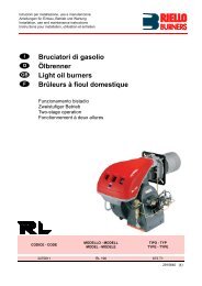
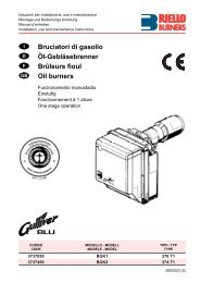
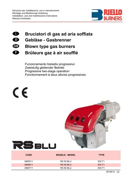
<strong>Bruciatori</strong> <strong>di</strong> <strong>gas</strong> <strong>ad</strong> <strong>aria</strong> <strong>soffiata</strong><br />
<strong>Gebläse</strong> - <strong>Gasbrenner</strong><br />
<strong>Blown</strong> <strong>type</strong> <strong>gas</strong> burners<br />
Brûleurs gaz à air soufflé<br />
Funzionamento bista<strong>di</strong>o progressivo<br />
Zweistufig gleitender Betrieb<br />
Progressive two-stage operation<br />
Fonctionnement à deux allures progressives<br />
CODE MODELE - MODEL TYPE<br />
3895511 RS 55 BLU 832 T1<br />
3895611 RS 65 BLU 833 T1<br />
3895711 RS 85 BLU 834 T1<br />
2915612 (3)
3<br />
INDICE<br />
DATI TECNICI . . . . . . . . . . . . . . . . . . . . . . . . . . . . . . . . . pagina 4<br />
Accessori . . . . . . . . . . . . . . . . . . . . . . . . . . . . . . . . . . . . . . . . . . . 4<br />
Descrizione bruciatore . . . . . . . . . . . . . . . . . . . . . . . . . . . . . . . . . 8<br />
Imballo - Peso. . . . . . . . . . . . . . . . . . . . . . . . . . . . . . . . . . . . . . . . 8<br />
Ingombro . . . . . . . . . . . . . . . . . . . . . . . . . . . . . . . . . . . . . . . . . . . 8<br />
Corredo . . . . . . . . . . . . . . . . . . . . . . . . . . . . . . . . . . . . . . . . . . . . 8<br />
Campi <strong>di</strong> lavoro. . . . . . . . . . . . . . . . . . . . . . . . . . . . . . . . . . . . . . 10<br />
Caldaia <strong>di</strong> prova . . . . . . . . . . . . . . . . . . . . . . . . . . . . . . . . . . . . . 10<br />
Caldaie commerciali . . . . . . . . . . . . . . . . . . . . . . . . . . . . . . . . . . 10<br />
Pressione <strong>gas</strong>. . . . . . . . . . . . . . . . . . . . . . . . . . . . . . . . . . . . . . . 12<br />
INSTALLAZIONE. . . . . . . . . . . . . . . . . . . . . . . . . . . . . . . . . . . . 14<br />
Piastra caldaia . . . . . . . . . . . . . . . . . . . . . . . . . . . . . . . . . . . . . . 14<br />
Lunghezza boccaglio . . . . . . . . . . . . . . . . . . . . . . . . . . . . . . . . . 14<br />
Fissaggio del bruciatore alla caldaia . . . . . . . . . . . . . . . . . . . . . 14<br />
Regolazione testa <strong>di</strong> combustione . . . . . . . . . . . . . . . . . . . . . . . 16<br />
Linea alimentazione <strong>gas</strong>. . . . . . . . . . . . . . . . . . . . . . . . . . . . . . . 18<br />
Impianto elettrico . . . . . . . . . . . . . . . . . . . . . . . . . . . . . . . . . . . . 20<br />
Regolazioni prima dell’accensione. . . . . . . . . . . . . . . . . . . . . . . 26<br />
Avviamento bruciatore . . . . . . . . . . . . . . . . . . . . . . . . . . . . . . . . 26<br />
Accensione bruciatore . . . . . . . . . . . . . . . . . . . . . . . . . . . . . . . . 26<br />
Regolazione bruciatore: . . . . . . . . . . . . . . . . . . . . . . . . . . . . . . . 28<br />
1 - Potenza all’accensione . . . . . . . . . . . . . . . . . . . . . . . . . . . . . 28<br />
2 - Potenza in 2° sta<strong>di</strong>o . . . . . . . . . . . . . . . . . . . . . . . . . . . . . . . 28<br />
3 - Potenza in 1° sta<strong>di</strong>o . . . . . . . . . . . . . . . . . . . . . . . . . . . . . . . 30<br />
4 - Potenze interme<strong>di</strong>e . . . . . . . . . . . . . . . . . . . . . . . . . . . . . . . . 30<br />
5 - Pressostato <strong>aria</strong> . . . . . . . . . . . . . . . . . . . . . . . . . . . . . . . . . . 32<br />
6 - Pressostato <strong>gas</strong> <strong>di</strong> minima . . . . . . . . . . . . . . . . . . . . . . . . . . 32<br />
Controllo presenza fiamma . . . . . . . . . . . . . . . . . . . . . . . . . . . . 32<br />
Funzionamento bruciatore . . . . . . . . . . . . . . . . . . . . . . . . . . . . . 34<br />
Controlli finali . . . . . . . . . . . . . . . . . . . . . . . . . . . . . . . . . . . . . . . 36<br />
Manutenzione. . . . . . . . . . . . . . . . . . . . . . . . . . . . . . . . . . . . . . . 36<br />
STATUS . . . . . . . . . . . . . . . . . . . . . . . . . . . . . . . . . . . . . . . . . . . 38<br />
Inconvenienti - Cause - Rime<strong>di</strong> . . . . . . . . . . . . . . . . . . . . . . . . . 40<br />
Avvertenza<br />
Le figure richiamate nel testo sono così in<strong>di</strong>cate:<br />
1)(A)<br />
=Particolare 1 della figura A nella stessa pagina del testo;<br />
1)(A)p.4 =Particolare 1 della figura A riportata a pagina 4.<br />
I<br />
INHALT<br />
TECHNISCHE ANGABEN . . . . . . . . . . . . . . . . . . . . . . . . . Seite 5<br />
Zubehör. . . . . . . . . . . . . . . . . . . . . . . . . . . . . . . . . . . . . . . . . . . . . 5<br />
Brennerbeschreibung . . . . . . . . . . . . . . . . . . . . . . . . . . . . . . . . . . 9<br />
Verpackung - Gewicht . . . . . . . . . . . . . . . . . . . . . . . . . . . . . . . . . . 9<br />
Abmessungen . . . . . . . . . . . . . . . . . . . . . . . . . . . . . . . . . . . . . . . . 9<br />
Ausstattung . . . . . . . . . . . . . . . . . . . . . . . . . . . . . . . . . . . . . . . . . . 9<br />
Regelbereiche . . . . . . . . . . . . . . . . . . . . . . . . . . . . . . . . . . . . . . . 11<br />
Prüfkessel . . . . . . . . . . . . . . . . . . . . . . . . . . . . . . . . . . . . . . . . . . 11<br />
Handelsübliche Kessel . . . . . . . . . . . . . . . . . . . . . . . . . . . . . . . . 11<br />
Gasdruck . . . . . . . . . . . . . . . . . . . . . . . . . . . . . . . . . . . . . . . . . . . 13<br />
INSTALLATION. . . . . . . . . . . . . . . . . . . . . . . . . . . . . . . . . . . . . . 15<br />
Kesselplatte. . . . . . . . . . . . . . . . . . . . . . . . . . . . . . . . . . . . . . . . . 15<br />
Flammrohrlänge . . . . . . . . . . . . . . . . . . . . . . . . . . . . . . . . . . . . . 15<br />
Befestigung des Brenners am Heizkessel. . . . . . . . . . . . . . . . . . 15<br />
Einstellung des Flammkopfs . . . . . . . . . . . . . . . . . . . . . . . . . . . . 17<br />
Gaszuleitung . . . . . . . . . . . . . . . . . . . . . . . . . . . . . . . . . . . . . . . . 19<br />
Elektroanlage . . . . . . . . . . . . . . . . . . . . . . . . . . . . . . . . . . . . . . . 21<br />
Einstellungen vor der Zündung . . . . . . . . . . . . . . . . . . . . . . . . . . 27<br />
Anfahren des Brenners . . . . . . . . . . . . . . . . . . . . . . . . . . . . . . . . 27<br />
Zündung des Brenners . . . . . . . . . . . . . . . . . . . . . . . . . . . . . . . . 27<br />
Brennereinstellung: . . . . . . . . . . . . . . . . . . . . . . . . . . . . . . . . . . . 29<br />
1 - Zündleistung. . . . . . . . . . . . . . . . . . . . . . . . . . . . . . . . . . . . . . 29<br />
2 - Leistung auf 2. Stufe . . . . . . . . . . . . . . . . . . . . . . . . . . . . . . . 29<br />
3 - Leistung auf 1. Stufe . . . . . . . . . . . . . . . . . . . . . . . . . . . . . . . 31<br />
4 - Zwischenleistungen . . . . . . . . . . . . . . . . . . . . . . . . . . . . . . . . 31<br />
5 - Luft-Druckwächter . . . . . . . . . . . . . . . . . . . . . . . . . . . . . . . . . 33<br />
6 - Gas-Mindestdruckwächter . . . . . . . . . . . . . . . . . . . . . . . . . . . 33<br />
Flammenüberwachung . . . . . . . . . . . . . . . . . . . . . . . . . . . . . . . . 33<br />
Brennerbetrieb . . . . . . . . . . . . . . . . . . . . . . . . . . . . . . . . . . . . . . 35<br />
Endkontrollen . . . . . . . . . . . . . . . . . . . . . . . . . . . . . . . . . . . . . . . 37<br />
Wartung. . . . . . . . . . . . . . . . . . . . . . . . . . . . . . . . . . . . . . . . . . . . 37<br />
STATUS . . . . . . . . . . . . . . . . . . . . . . . . . . . . . . . . . . . . . . . . . . . . 39<br />
Störungen - Ursachen - Abhilfen . . . . . . . . . . . . . . . . . . . . . . . . . 41<br />
Anmerkung<br />
Die Zeichnungen, auf <strong>di</strong>e im Text Bezug genommen wird, werden<br />
folgendermaßen bezeichnet:<br />
1)(A)<br />
=Detail 1 der Zeichnung A auf der gleichen Textseite;<br />
1)(A)p.4 =Detail 1 der Zeichnung A auf Seite 4.<br />
D<br />
CONTENTS<br />
TECHNICAL DATA . . . . . . . . . . . . . . . . . . . . . . . . . . . . . . page 6<br />
Accessories . . . . . . . . . . . . . . . . . . . . . . . . . . . . . . . . . . . . . . . . . 6<br />
Burner description . . . . . . . . . . . . . . . . . . . . . . . . . . . . . . . . . . . . 9<br />
Packaging - Weight. . . . . . . . . . . . . . . . . . . . . . . . . . . . . . . . . . . . 9<br />
Max. <strong>di</strong>mensions. . . . . . . . . . . . . . . . . . . . . . . . . . . . . . . . . . . . . . 9<br />
Standard equipment . . . . . . . . . . . . . . . . . . . . . . . . . . . . . . . . . . . 9<br />
Firing rates . . . . . . . . . . . . . . . . . . . . . . . . . . . . . . . . . . . . . . . . . 11<br />
Test boiler . . . . . . . . . . . . . . . . . . . . . . . . . . . . . . . . . . . . . . . . . . 11<br />
Commercial boilers. . . . . . . . . . . . . . . . . . . . . . . . . . . . . . . . . . . 11<br />
Gas pressure . . . . . . . . . . . . . . . . . . . . . . . . . . . . . . . . . . . . . . . 13<br />
INSTALLATION . . . . . . . . . . . . . . . . . . . . . . . . . . . . . . . . . . . . . 15<br />
Boiler plate . . . . . . . . . . . . . . . . . . . . . . . . . . . . . . . . . . . . . . . . . 15<br />
Blast tube length . . . . . . . . . . . . . . . . . . . . . . . . . . . . . . . . . . . . 15<br />
Securing the burner to the boiler . . . . . . . . . . . . . . . . . . . . . . . . 15<br />
Combustion he<strong>ad</strong> setting . . . . . . . . . . . . . . . . . . . . . . . . . . . . . . 17<br />
Gas line . . . . . . . . . . . . . . . . . . . . . . . . . . . . . . . . . . . . . . . . . . . 19<br />
Electrical system . . . . . . . . . . . . . . . . . . . . . . . . . . . . . . . . . . . . 21<br />
Adjustments before firing . . . . . . . . . . . . . . . . . . . . . . . . . . . . . . 27<br />
Burner starting . . . . . . . . . . . . . . . . . . . . . . . . . . . . . . . . . . . . . . 27<br />
Burner firing . . . . . . . . . . . . . . . . . . . . . . . . . . . . . . . . . . . . . . . . 27<br />
Burner calibration: . . . . . . . . . . . . . . . . . . . . . . . . . . . . . . . . . . . 29<br />
1 - Firing output . . . . . . . . . . . . . . . . . . . . . . . . . . . . . . . . . . . . . 29<br />
2 - 2nd stage output . . . . . . . . . . . . . . . . . . . . . . . . . . . . . . . . . . 29<br />
3 -1st stage output . . . . . . . . . . . . . . . . . . . . . . . . . . . . . . . . . . . 31<br />
4 - Interme<strong>di</strong>ates outputs . . . . . . . . . . . . . . . . . . . . . . . . . . . . . . 31<br />
5 - Air pressure switch . . . . . . . . . . . . . . . . . . . . . . . . . . . . . . . . 33<br />
6 - Minimum <strong>gas</strong> pressure switch. . . . . . . . . . . . . . . . . . . . . . . . 33<br />
Flame present check . . . . . . . . . . . . . . . . . . . . . . . . . . . . . . . . . 33<br />
Burner operation. . . . . . . . . . . . . . . . . . . . . . . . . . . . . . . . . . . . . 35<br />
Final checks . . . . . . . . . . . . . . . . . . . . . . . . . . . . . . . . . . . . . . . . 37<br />
Maintenance. . . . . . . . . . . . . . . . . . . . . . . . . . . . . . . . . . . . . . . . 37<br />
STATUS . . . . . . . . . . . . . . . . . . . . . . . . . . . . . . . . . . . . . . . . . . . 39<br />
Fault - Probable cause - Suggested remedy . . . . . . . . . . . . . . . 42<br />
N.B.<br />
Figures mentioned in the text are identified as follows:<br />
1)(A)<br />
=part 1 of figure A, same page as text;<br />
1)(A)p.4 =part 1 of figure A, page number 4.<br />
GB<br />
INDEX<br />
DONNÉES TECHNIQUES . . . . . . . . . . . . . . . . . . . . . . . . . page 7<br />
Accesoires. . . . . . . . . . . . . . . . . . . . . . . . . . . . . . . . . . . . . . . . . . . 7<br />
Description brûleur . . . . . . . . . . . . . . . . . . . . . . . . . . . . . . . . . . . . 9<br />
Emballage - Poids . . . . . . . . . . . . . . . . . . . . . . . . . . . . . . . . . . . . . 9<br />
Encombrement . . . . . . . . . . . . . . . . . . . . . . . . . . . . . . . . . . . . . . . 9<br />
Equipement standard . . . . . . . . . . . . . . . . . . . . . . . . . . . . . . . . . . 9<br />
Plages de puissance . . . . . . . . . . . . . . . . . . . . . . . . . . . . . . . . . . 11<br />
Chau<strong>di</strong>ère d’essai . . . . . . . . . . . . . . . . . . . . . . . . . . . . . . . . . . . . 11<br />
Chau<strong>di</strong>ères commerciales. . . . . . . . . . . . . . . . . . . . . . . . . . . . . . 11<br />
Pression du gaz. . . . . . . . . . . . . . . . . . . . . . . . . . . . . . . . . . . . . . 13<br />
INSTALLATION. . . . . . . . . . . . . . . . . . . . . . . . . . . . . . . . . . . . . . 15<br />
Plaque chau<strong>di</strong>ère . . . . . . . . . . . . . . . . . . . . . . . . . . . . . . . . . . . . 15<br />
Longueur buse . . . . . . . . . . . . . . . . . . . . . . . . . . . . . . . . . . . . . . 15<br />
Fixation du brûleur à la chau<strong>di</strong>ère. . . . . . . . . . . . . . . . . . . . . . . . 15<br />
Réglage tête de combustion . . . . . . . . . . . . . . . . . . . . . . . . . . . . 17<br />
Ligne alimentation gaz . . . . . . . . . . . . . . . . . . . . . . . . . . . . . . . . 19<br />
Installation électrique . . . . . . . . . . . . . . . . . . . . . . . . . . . . . . . . . 21<br />
Réglages avant l’allumage . . . . . . . . . . . . . . . . . . . . . . . . . . . . . 27<br />
Démarrage brûleur . . . . . . . . . . . . . . . . . . . . . . . . . . . . . . . . . . . 27<br />
Allumage brûleur . . . . . . . . . . . . . . . . . . . . . . . . . . . . . . . . . . . . . 27<br />
Réglage brûleur: . . . . . . . . . . . . . . . . . . . . . . . . . . . . . . . . . . . . . 29<br />
1 - Puissance à l’allumage . . . . . . . . . . . . . . . . . . . . . . . . . . . . . 29<br />
2 - Puissance en 2ème allure . . . . . . . . . . . . . . . . . . . . . . . . . . . 29<br />
3 - Puissance en 1ère allure . . . . . . . . . . . . . . . . . . . . . . . . . . . . 31<br />
4 - Puissances intermé<strong>di</strong>ares . . . . . . . . . . . . . . . . . . . . . . . . . . . 31<br />
5 - Pressostat de l’air. . . . . . . . . . . . . . . . . . . . . . . . . . . . . . . . . . 33<br />
6 - Pressostat gaz seuil minimum . . . . . . . . . . . . . . . . . . . . . . . . 33<br />
Contrôle présence flamme . . . . . . . . . . . . . . . . . . . . . . . . . . . . . 33<br />
Fonctionnement brûleur . . . . . . . . . . . . . . . . . . . . . . . . . . . . . . . 35<br />
Contrôles finaux . . . . . . . . . . . . . . . . . . . . . . . . . . . . . . . . . . . . . 37<br />
Entretien . . . . . . . . . . . . . . . . . . . . . . . . . . . . . . . . . . . . . . . . . . . 37<br />
STATUS . . . . . . . . . . . . . . . . . . . . . . . . . . . . . . . . . . . . . . . . . . . . 39<br />
Inconvénients - Causes - Rimèdes . . . . . . . . . . . . . . . . . . . . . . . 43<br />
Attention<br />
Les figures rappelées dans le texte sont ainsi in<strong>di</strong>quées:<br />
1)(A)<br />
=Détail 1 de la figure A dans la même page du texte;<br />
1)(A)p.4 =Détail 1 de la figure A page 4.<br />
F
DATI TECNICI<br />
I<br />
MODELLO RS 55 BLU RS 65 BLU RS 85 BLU<br />
TIPO 832 T1 833 T1 834 T1<br />
POTENZA (1) 2° sta<strong>di</strong>o kW 407 - 640<br />
616 - 814<br />
790 - 1000<br />
Mcal/h 350 - 550<br />
530 - 700<br />
680 - 860<br />
min. 1° sta<strong>di</strong>o kW 204<br />
308<br />
400<br />
Mcal/h 176<br />
265<br />
344<br />
COMBUSTIBILE<br />
GAS NATURALE: G20 - G21 - G22 - G23 - G25<br />
G20 G25 G20 G25 G20 G25<br />
- potere calorifico inferiore kWh/Nm 3<br />
Mcal/Nm 3 10<br />
8,6<br />
- densità assoluta kg/Nm 3 0,71 0,78 0,71 0,78 0,71 0,78<br />
- portata massima Nm 3 /h 64 74,5 81,4 94,5 100 116<br />
- pressione alla portata massima (2) mbar 7,1 9,2 11 14,3 12,6 16,4<br />
FUNZIONAMENTO<br />
• Intermittente (min. 1 arresto in 24 ore).<br />
• Bista<strong>di</strong>o (alta e bassa fiamma) e monosta<strong>di</strong>o (tutto - niente).<br />
IMPIEGO STANDARD<br />
Caldaie: <strong>ad</strong> acqua, a vapore, <strong>ad</strong> olio <strong>di</strong>atermico<br />
TEMPERATURA AMBIENTE °C 0 - 40<br />
TEMPERATURA ARIA COMBURENTE °C max 60<br />
ALIMENTAZIONE ELETTRICA<br />
V<br />
Hz<br />
230 - 400 con neutro +/-10%<br />
50 - trifase ~<br />
MOTORE ELETTRICO<br />
TRASFORMATORE D’ACCENSIONE<br />
rpm<br />
W<br />
V<br />
A<br />
V1 - V2<br />
I1 - I2<br />
(1) Con<strong>di</strong>zioni <strong>di</strong> riferimento: Temperatura ambiente 20°C - Pressione barometrica 1000 mbar - Altitu<strong>di</strong>ne 100 m s.l.m.<br />
(2) Pressione alla presa 16)(A)p.8 con pressione zero in camera <strong>di</strong> combustione, con la ghiera del <strong>gas</strong> 2)(B)p.12 aperta ed alla potenza massima<br />
del bruciatore<br />
(3) Pressione sonora misurata nel laboratorio combustione del costruttore, con bruciatore funzionante su caldaia <strong>di</strong> prova, alla potenza massima.<br />
8,6<br />
7,4<br />
2800<br />
1100<br />
220/240 - 380/415<br />
4,8 - 2,8<br />
230 V - 1 x 8 kV<br />
1 A - 20 mA<br />
10<br />
8,6<br />
8,6<br />
7,4<br />
2800<br />
1500<br />
220/240 - 380/415<br />
5,9 - 3,4<br />
10<br />
8,6<br />
8,6<br />
7,4<br />
2800<br />
2200<br />
220/240 - 380/415<br />
8,8 - 5,1<br />
POTENZA ELETTRICA ASSORBITA W max 1400 1800 2600<br />
GRADO DI PROTEZIONE IP 44<br />
CONFORMITÀ DIRETTIVE CEE 90/396 - 89/336 - 73/23 - 98/37<br />
RUMOROSITÀ (3) dBA 75 77 78,5<br />
OMOLOGAZIONE CE 0085AS0431 0085AS0431 0085AS0431<br />
PAESE<br />
SE - FI - AT - GR - DK -ES - GB - IT - IE - PT - IS - CH - NO<br />
DE<br />
NL<br />
FR<br />
BE<br />
LU<br />
CATEGORIA<br />
I 2H<br />
I 2ELL<br />
I 2L<br />
I 2Er<br />
I 2E(R)B<br />
I 2E<br />
ACCESSORI (su richiesta):<br />
• RAMPE GAS SECONDO NORMA EN 676 (complete <strong>di</strong> valvole, regolatore <strong>di</strong> pressione e filtro): vedere a pagina 18.<br />
Importante:<br />
L’installatore è responsabile per l’eventuale aggiunta <strong>di</strong> organi <strong>di</strong> sicurezza non previsti in questo manuale.<br />
4
TECHNISCHE ANGABEN<br />
D<br />
MODELL RS 55 BLU RS 65 BLU RS 85 BLU<br />
TYP 832 T1 833 T1 834 T1<br />
LEISTUNG (1) 2. Stufe kW 407 - 640<br />
616 - 814<br />
790 - 1000<br />
Mcal/h 350 - 550<br />
530 - 700<br />
680 - 860<br />
min. 1. Stufe kW 204<br />
308<br />
400<br />
Mcal/h 176<br />
265<br />
344<br />
BRENNSTOFF<br />
ERDGAS: G20 - G21 - G22 - G23 - G25<br />
G20 G25 G20 G25 G20 G25<br />
- Unterer Heizwert Hu kWh/Nm 3<br />
Mcal/kg<br />
10<br />
8,6<br />
8,6<br />
7,4<br />
10<br />
8,6<br />
8,6<br />
7,4<br />
10<br />
8,6<br />
8,6<br />
7,4<br />
- Rein<strong>di</strong>chte kg/Nm 3 0,71 0,78 0,71 0,78 0,71 0,78<br />
- Höchstdurchsatz Nm 3 /h 64 74,5 81,4 94,5 100 116<br />
- Druck bei Höchstdurchsatz (2) mbar 7,1 9,2 11 14,3 12,6 16,4<br />
BETRIEB<br />
• Aussetzend (min. 1 Halt in 24 Std).<br />
• Zweistufig (hohe und niedrige Flamme) - einstufig (alles - nichts).<br />
STANDARDEINSATZ<br />
Heizkessel: mit Wasser, Dampf, <strong>di</strong>athermischem Öl<br />
RAUMTEMPERATUR °C 0 - 40<br />
TEMPERATUR VERBRENNUNGSLUFT °C max 60<br />
ELEKTRISCHE SPEISUNG<br />
V<br />
Hz<br />
230 - 400 mit Nulleiter ~ +/-10%<br />
50 - dreiphasig<br />
ELEKTROMOTOR<br />
ZÜNDTRANSFORMATOR<br />
rpm<br />
W<br />
V<br />
A<br />
V1 - V2<br />
I1 - I2<br />
2800<br />
1100<br />
220/240 - 380/415<br />
4,8 - 2,8<br />
230 V - 1 x 8 kV<br />
1 A - 20 mA<br />
2800<br />
1500<br />
220/240 - 380/415<br />
5,9 - 3,4<br />
2800<br />
220/0<br />
220/240 - 380/415<br />
8,8 - 5,1<br />
ELEKTRISCHE LEISTUNGSAUFNAHME W max 1400 1800 2600<br />
SCHUTZART IP 44<br />
CE-NORMGERECHT 90/396 - 89/336 - 73/23 - 98/37<br />
SCHALLDRUCKPEGEL (3) dBA 75 77 78,5<br />
OMOLOGAZIONE CE 0085AS0431 0085AS0431 0085AS0431<br />
(1) Bezugsbe<strong>di</strong>ngungen: Raumtemperatur 20°C - Barometrischer Druck 1000 mbar - Höhe 100 m ü.d.M.<br />
(2) Druck am Anschluß 16)(A)S.8 bei druckloser Brennkammer, geöffneter Gasscheibe 2)(B)S.12 und bei Höchstleistung des Brenners<br />
(3) Schalldruck, im Brennprüflabor des Herstellers mit Brenner auf Prüfkessel bei Höchstleistung.<br />
LAND<br />
SE - FI - AT - GR - DK -ES - GB - IT - IE - PT - IS - CH - NO<br />
DE<br />
NL<br />
FR<br />
BE<br />
LU<br />
KATEGORIE<br />
I 2H<br />
I 2ELL<br />
I 2L<br />
I 2Er<br />
I 2E(R)B<br />
I 2E<br />
ZUBEHÖR (auf Wunsch):<br />
• GASARMATUREN GEMÄß NORM EN 676 (mit Ventilen, Druckregler und Filter): siehe Seite 18.<br />
Wichtiger Hinweis:<br />
Der Installateur haftet für den eventuellen Zusatz von Sicherheitsteilen, <strong>di</strong>e nicht in <strong>di</strong>eser Betriebsanleitung vorgesehen sind.<br />
5
TECHNICAL DATA<br />
GB<br />
MODEL RS 55 BLU RS 65 BLU RS 85 BLU<br />
TYP 832 T1 833 T1 834 T1<br />
OUTPUT (1) 2nd stage kW 407 - 640<br />
616 - 814<br />
790 - 1000<br />
Mcal/h 350 - 550<br />
530 - 700<br />
680 - 860<br />
min. 1st stage kW 204<br />
308<br />
400<br />
Mcal/h 176<br />
265<br />
344<br />
FUEL<br />
NATURAL GAS: G20 - G21 - G22 - G23 - G25<br />
G20 G25 G20 G25 G20 G25<br />
- net calorific value kWh/Nm 3<br />
Mcal/Nm 3 10<br />
8.6<br />
- absolute density kg/Nm 3 0.71 0.78 0.71 0.78 0.71 0.78<br />
- max. delivery Nm 3 /h 64 74.5 81.4 94.5 100 116<br />
- pressure at max. delivery mbar 7.1 9.2 11 14.3 12.6 16.4<br />
OPERATION<br />
• On-Off (1 stop min each 24 hours).<br />
• Two-stage (high and low flame) and single stage (all - nothing)<br />
STANDARD APPLICATIONS<br />
Boilers: water, steam, <strong>di</strong>athermic oil<br />
AMBIENT TEMPERATUR °C 0 - 40<br />
COMBUSTION AIR TEMPERATURE °C max 60<br />
ELECTRICAL SUPPLY<br />
V<br />
Hz<br />
230 - 400 with neutral +/-10%<br />
50 - three-phaes ~<br />
ELECTRIC MOTOR<br />
IGNITION TRANSFORMER<br />
rpm<br />
W<br />
V<br />
A<br />
V1 - V2<br />
I1 - I2<br />
(1) Reference con<strong>di</strong>tions: Ambient temperature 20°C - Barometric pressure 1000 mbar - Altitude 100 m s.l.m.<br />
(2) Pressure at test point 16)(A)p.8, with zero pressure in the combustion chambre, with open <strong>gas</strong> ring 2)(B)p.12 an maximum burner output<br />
(2) Sound pressure measured in manufacturer’s combustion laboratory, with burner operating on test boiler and at maximum rated output.<br />
8.6<br />
7.4<br />
2800<br />
1100<br />
220/240 - 380/415<br />
4.8 - 2.8<br />
230 V - 1 x 8 kV<br />
1 A - 20 mA<br />
10<br />
8.6<br />
8.6<br />
7.4<br />
2800<br />
1500<br />
220/240 - 380/415<br />
5.9 - 3.4<br />
10<br />
8.6<br />
8.6<br />
7.4<br />
2800<br />
2200<br />
220/240 - 380/415<br />
8.8 - 5.1<br />
ELECTRICAL POWER CONSUMPTION W max 1400 1800 2600<br />
ELECTRICAL PROTECTION IP 44<br />
IN CONFORMITY WITH EEC DIRECTIVES 90/396 - 89/336 - 73/23 - 98/37<br />
NOISE LEVELS (2) dBA 75 77 78.5<br />
APPROVAL CE 0085AS0431 0085AS0431 0085AS0431<br />
COUNTRY<br />
SE - FI - AT - GR - DK -ES - GB - IT - IE - PT - IS - CH - NO<br />
DE<br />
NL<br />
FR<br />
BE<br />
LU<br />
CATEGORY<br />
I 2H<br />
I 2ELL<br />
I 2L<br />
I 2Er<br />
I 2E(R)B<br />
I 2E<br />
ACCESSORIES (optional):<br />
• GAS TRAIN ACCORDING TO REGULATION EN 676 (with valve, pressure governor and filter): see page 18.<br />
Important:<br />
The installer is responsible for the <strong>ad</strong><strong>di</strong>tion of any safety device not forseen in the present manual.<br />
6
DONNEES TECHNIQUES<br />
F<br />
MODELE RS 55 BLU RS 65 BLU RS 85 BLU<br />
TYPE 832 T1 833 T1 834 T1<br />
PUISSANCE (1) 2ème allure kW 407 - 640<br />
616 - 814<br />
790 - 1000<br />
Mcal/h 350 - 550<br />
530 - 700<br />
680 - 860<br />
min. 1ère allure kW 204<br />
308<br />
400<br />
Mcal/h 176<br />
265<br />
344<br />
COMBUSTIBLE<br />
GAZ NATUREL: G20 - G21 - G22 - G23 - G25<br />
G20 G25 G20 G25 G20 G25<br />
- pouvoir calorifique inférieur kWh/Nm 3<br />
Mcal/Nm 3 10<br />
8,6<br />
- densité absolue kg/Nm 3 0,71 0,78 0,71 0,78 0,71 0,78<br />
- pression au débit max. Nm 3 /h 64 74,5 81,4 94,5 100 116<br />
- pression au débit max. (2) mbar 7,1 9,2 11 14,3 12,6 16,4<br />
FONCTIONNEMENT<br />
• Intermittent (1 arrêt min en 24 heures)<br />
• 2 allures (flamme haute et basse) et une allure (tout - rien)<br />
EMPLOI STANDARD<br />
Chau<strong>di</strong>ères à eau, à vapeur, à huile <strong>di</strong>athermique<br />
TEMPERATURE AMBIANTE °C 0 - 40<br />
TEMPERATURE AIR COMBURANT °C max 60<br />
ALIMENTATION ELECTRIQUES<br />
V<br />
Hz<br />
230 - 400 avec neutre +/-10%<br />
50 - triphasée ~<br />
MOTEUR ELECTRIQUE<br />
TRANSFORMATEUR D’ALLUMAGE<br />
rpm<br />
W<br />
V<br />
A<br />
V1 - V2<br />
I1 - I2<br />
(1) Con<strong>di</strong>tions de référence: Température ambiante 20°C - Pression barométrique 1000 mbar - Altitude 100 m au-dessus du niveau de la mer.<br />
(2) Pression à la prise 16)(A)p.8, avec une pression nulle dans la chambre de combustion, avec la bague du gaz 2)(B)p.12 ouverte et à la puissance<br />
maximum du brûleur.<br />
(3) Pression acoustique mesurée dans le laboratoire combustion du constructeur, le brûleur fonctionnant sur une chau<strong>di</strong>ère d’essai à la puissance<br />
maximum.<br />
8,6<br />
7,4<br />
2800<br />
1100<br />
220/240 - 380/415<br />
4,8 - 2,8<br />
230 V - 1 x 8 kV<br />
1 A - 20 mA<br />
10<br />
8,6<br />
8,6<br />
7,4<br />
2800<br />
1500<br />
220/240 - 380/415<br />
5,9 - 3,4<br />
10<br />
8,6<br />
8,6<br />
7,4<br />
2800<br />
2200<br />
220/240 - 380/415<br />
8,8 - 5,1<br />
PUISSANCE ELECTRIQUE ABSORBEE W max 1400 1800 2600<br />
DEGRE DE PROTECTION IP 44<br />
CONFORMÉMENT AUX DIRECTIVES CEE 90/396 - 89/336 - 73/23 - 98/37<br />
NIVEAU DE BRUIT (2) dBA 75 77 78,5<br />
HOMOLOGATION CE 0085AS0431 0085AS0431 0085AS0431<br />
PAYS<br />
SE - FI - AT - GR - DK -ES - GB - IT - IE - PT - IS - CH - NO<br />
DE<br />
NL<br />
FR<br />
BE<br />
LU<br />
CATEGORIE<br />
I 2H<br />
I 2ELL<br />
I 2L<br />
I 2Er<br />
I 2E(R)B<br />
I 2E<br />
ACCESSOIRES (sur demande):<br />
• RAMPES GAZ SELON LA NORME EN 676 (avec vannes, regulateur de pression et filtre): voir p. 18.<br />
Attention:<br />
Si l’installateur ajoute des organes de sécurité non prévus dans ce manuel, il en assume la responsabilité.<br />
7
(A)<br />
mm A B C kg<br />
RS 55 BLU 1190 740 692 70<br />
RS 65 BLU 1190 740 692 73<br />
RS 85 BLU 1190 740 692 76<br />
(B)<br />
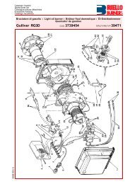
DESCRIZIONE BRUCIATORE (A)<br />
1 Testa <strong>di</strong> combustione<br />
2 Elettrodo <strong>di</strong> accensione<br />
3 Vite per regolazione testa <strong>di</strong> combustione<br />
4 Manicotto<br />
5 Servomotore, comanda la farfalla del <strong>gas</strong> e,<br />
tramite una camma a profilo v<strong>aria</strong>bile, la serranda<br />
dell’<strong>aria</strong>.<br />
Durante la sosta del bruciatore la serranda<br />
dell’<strong>aria</strong> è completamente chiusa per ridurre<br />
al minimo le <strong>di</strong>spersioni termiche della caldaia<br />
dovute al tiraggio del camino che<br />
richiama l’<strong>aria</strong> dalla bocca <strong>di</strong> aspirazione del<br />
ventilatore<br />
6 Spina-presa sul cavo della sonda <strong>di</strong> ionizzazione<br />
7 Contattore motore e relè termico con pulsante<br />
<strong>di</strong> sblocco<br />
8 STATUS<br />
9 Morsettiera<br />
10 Passacavi per i collegamenti elettrici a cura<br />
dell’installatore<br />
11 Due interruttori elettrici:<br />
- uno per “acceso - spento bruciatore”<br />
- uno per “1° - 2° sta<strong>di</strong>o”<br />
12 Apparecchiatura elettrica con avvisatore<br />
luminoso <strong>di</strong> blocco e pulsante <strong>di</strong> sblocco<br />
13 Visore fiamma<br />
14 Pressostato <strong>aria</strong> <strong>di</strong> minima<br />
(tipo <strong>di</strong>fferenziale)<br />
15 Guide per apertura bruciatore ed ispezione<br />
alla testa <strong>di</strong> combustione<br />
16 Presa <strong>di</strong> pressione <strong>gas</strong> e vite fissa testa<br />
17 Presa <strong>di</strong> pressione <strong>aria</strong><br />
18 Sonda per il controllo presenza fiamma<br />
19 Serranda <strong>aria</strong><br />
20 Ingresso <strong>aria</strong> nel ventilatore<br />
21 Viti per il fissaggio ventilatore al manicotto<br />
22 Condotto arrivo <strong>gas</strong><br />
23 Valvola farfalla <strong>gas</strong><br />
24 Flangia per il fissaggio alla caldaia<br />
25 Disco <strong>di</strong> stabilità fiamma<br />
Vi sono due possibilità <strong>di</strong> blocco del bruciatore:<br />
Blocco apparecchiatura: l’accensione del pulsante<br />
dell’apparecchiatura 12)(A) avverte che il<br />
bruciatore è in blocco.<br />
Per sbloccare premere il pulsante.<br />
Blocco motore: per sbloccare premere il pulsante<br />
del relè termico 7)(A).<br />
IMBALLO - PESO (B) - misure in<strong>di</strong>cative<br />
• L’ imballo del bruciatore appoggia su una<br />
pedana in legno particolarmente <strong>ad</strong>atta ai carrelli<br />
elevatori. Le <strong>di</strong>mensioni <strong>di</strong> ingombro<br />
dell'imballo sono riportate nella tabella (B).<br />
• Il peso del bruciatore completo <strong>di</strong> imballo è<br />
in<strong>di</strong>cato nella tabella (B).<br />
INGOMBRO (C) - misure in<strong>di</strong>cative<br />
L'ingombro del bruciatore è riportato in fig. (C).<br />
Tener presente che per ispezionare la testa <strong>di</strong><br />
combustione il bruciatore deve essere aperto<br />
arretrandone la parte posteriore sulle guide.<br />
L'ingombro del bruciatore aperto è in<strong>di</strong>cato dalla<br />
quota I.<br />
mm A B C D E F G H I L M N O<br />
RS 55 BLU 511 296 215 555 840 255 189 430 1161 214 134 221 2”<br />
RS 65 BLU 527 312 215 555 840 255 189 430 1161 214 134 221 2”<br />
RS 85 BLU 553 338 215 555 840 255 189 430 1161 214 134 221 2”<br />
CORREDO<br />
1 - Flangia per rampa <strong>gas</strong><br />
1 - Guarnizione per flangia<br />
4 - Viti per fissare la flangia M 10 x 35<br />
1 - Schermo termico<br />
4 - Viti per fissare la flangia del bruciatore alla<br />
caldaia: M 12 x 35<br />
1 - Istruzione<br />
1 - Catalogo ricambi<br />
(C)<br />
8
BRENNERBESCHREIBUNG (A)<br />
1 Flammkopf<br />
2 Zündelektrode<br />
3 Einstellschraube des Flammkopfes<br />
4 Gasanschluß-Muffe<br />
5 Stellantrieb zur Steuerung der Gasdrossel<br />
und, über einen Nocken mit v<strong>aria</strong>blem Profil,<br />
der Luftklappe.<br />
Bei Brennerstillstand ist <strong>di</strong>e Luftklappe<br />
geschlossen, um <strong>di</strong>e Wärmeverluste des<br />
Kessels durch den Kaminzug mit Luftnachführung<br />
von der Saugöffnung des <strong>Gebläse</strong>s<br />
zu vermeiden<br />
6 Steckanschluß am Kabel der Ionisationssonde<br />
7 Motorschütz und Überstromauslöser mit Entriegelungsschalter<br />
8 STATUS<br />
9 Klemmenbrett<br />
10 Kabeldurchgänge für <strong>di</strong>e Elektroanschlüsse<br />
vom Installateur<br />
11 Zwei Schalter:<br />
- einer für “Brenner eingeschaltet-ausgeschaltet”<br />
- einer für “1. - 2. Stufe”<br />
12 Steuergerät mit Kontrollampe für Störabschaltung<br />
und Entriegelungsschalter<br />
13 Flammen-Sichtfenster<br />
14 Mindestluftdruckwächter<br />
(Differentialtyp)<br />
15 Gleitschienen zur Öffnung des Brenners und<br />
für <strong>di</strong>e Kontrolle des Flammkopfs<br />
16 Gasdruckentnahmestelle und Befestigungsschraube<br />
des Flammkopfes<br />
17 Luftdruckentnahmestelle<br />
18 Flammenfühler<br />
19 Luftklappe<br />
20 Lufteinlaß zum <strong>Gebläse</strong><br />
21 Befestigungsschraube des <strong>Gebläse</strong>s an der<br />
Gasanschluß-Muffe<br />
22 Gaszuleitung<br />
23 Gasdrossel<br />
24 Befestigungsflansch am Kessel<br />
25 Stauscheibe<br />
Die Störabschaltungen des Brenners können<br />
zweierlei Art sein:<br />
Störabschaltung des Gerätes: Das Aufleuchten<br />
des Druckknopfes des Gerätes 12)(A) weist auf<br />
eine Störabschaltung des Brenners hin.<br />
Zur Entriegelung den Druckknopf drücken.<br />
Störabschaltung des Motors: Entriegelung<br />
durch Drükken auf den Druckknopf des Überstromauslösers<br />
7)(A).<br />
VERPACKUNG - GEWICHT (B) - Richtwerte<br />
• Der Brenner steht auf einem besonders für<strong>di</strong>e<br />
Handhabung mit Hubwagen geeignetem<br />
Holzrahmen. Die Außenabmessungen der Verpackung<br />
sind in Tabelle (B) aufgeführt.<br />
• Das Gesamtgewicht des Brenners einschließlich<br />
Verpackung wird aus Tabelle (B)<br />
ersichtlich (B).<br />
ABMESSUNGEN (C) - Richtwerte<br />
Die Brennerabmessungen sind in der Abb. (C)<br />
angeführt.<br />
Zur Inspektion des Flammkopfes muß der Brenner<br />
zurückgeschoben und nach oben<br />
geschwenkt werden.<br />
Die Abmessungen des offenen Brenners, ohne<br />
Verkleidung, sind unter I aufgeführt.<br />
AUSSTATTUNG<br />
1 - Flansch für Gasarmaturen<br />
1 - Dichtung für Flansch<br />
4 - Schrauben für <strong>di</strong>e Befestigung des M10 x<br />
35 Flansches<br />
1 - Wärmeschild<br />
4 - Schrauben für <strong>di</strong>e Befestigung des Brennerflanschs<br />
am Kessel: M 12 x 35<br />
1 - Anleitung<br />
1 - Ersatzteile Katalog<br />
BURNER DESCRIPTION (A)<br />
1 Combustion he<strong>ad</strong><br />
2 Ignition electrode<br />
3 Screw for combustion he<strong>ad</strong> <strong>ad</strong>justment<br />
4 Sleeve<br />
5 Servomotor controlling the <strong>gas</strong> butterfly valve<br />
and of air gate valve (by means of a v<strong>aria</strong>ble<br />
profile cam mechanism).<br />
When the burner is not operating the air gate<br />
valve is fully closed in order to reduce heat<br />
<strong>di</strong>spersion from the boiler due to the flue<br />
draught which draws air from the fan suction<br />
inlet.<br />
6 Plug-socket on ionisation proble cable<br />
7 Motor contactor and thermal cut-out with<br />
reset button<br />
8 STATUS<br />
9 Terminal strip<br />
10 Fairle<strong>ad</strong>s for electrical connections by<br />
installer<br />
11 Two switches:<br />
- one “burner off-on”<br />
- one for “1st - 2nd stage operation”<br />
12 Control box with lock-out pilot light and lockout<br />
reset button<br />
13 Flame inspection window<br />
14 Minimum air pressure switch<br />
(<strong>di</strong>fferential operating <strong>type</strong>)<br />
15 Slide bars for opening the burner and<br />
inspecting the combustion he<strong>ad</strong><br />
16 Gas pressure test point and he<strong>ad</strong> fixing<br />
screw<br />
17 Air pressure test point<br />
18 Flame sensor probe<br />
19 Air gate valve<br />
20 Air inlet to fan<br />
21 Screws securing fan to sleeve<br />
22 Gas input pipework<br />
23 Gas butterfly valve<br />
24 Boiler mounting flange<br />
25 Flame stability <strong>di</strong>sk<br />
Two <strong>type</strong>s of burner failure may occur:<br />
Control Box Lock-out: if the control box 12)(A)<br />
pushbutton lights up, it in<strong>di</strong>cates that the burner<br />
is in lock-out.<br />
To reset, press the pushbutton.<br />
Motor trip: release by pressing the pushbutton<br />
on thermal relay 7)(A).<br />
PACKAGING - WEIGHT (B) - Approximate<br />
measurements<br />
• The burners stands on a wooden base which<br />
can be lifted by fork-lifts. Outer <strong>di</strong>mensions of<br />
packaging are in<strong>di</strong>cated in (B).<br />
• The weight of the burner complete with packaging<br />
is in<strong>di</strong>cated in Table (B).<br />
MAX. DIMENSIONS (C) - Approximate measurements<br />
The maximum <strong>di</strong>mensions of the burner are<br />
given in (C).<br />
Bear in mind that inspection of the combustion<br />
he<strong>ad</strong> requires the burner to be opened and the<br />
rear part withdrawn on the slide bars.<br />
The maximum <strong>di</strong>mension of the burner, without<br />
casing, when open is give by measurement I.<br />
STANDARD EQUIPMENT<br />
1 - Gas train flange<br />
1 - Flange <strong>gas</strong>ket<br />
4 - Flange fixing screws M 10 x 35<br />
1 - Thermal insulation screen<br />
4 - Screws to secure the burner flange to the<br />
boiler: M 12 x 35<br />
1 - Instruction booklet<br />
1 - Spare parts list<br />
DESCRIPTION BRULEUR (A)<br />
1 Tête de combustion<br />
2 Electrode d'allumage<br />
3 Vis pour réglage tête de combustion<br />
4 Manchon<br />
5 Servomoteur de commande de la vanne<br />
papillon du gaz et, par came à profil v<strong>aria</strong>ble,<br />
du volet d'air. Lors de l'arrêt du brûleur ce<br />
volet d'air est complètement fermé afin de<br />
réduire le plus possible les <strong>di</strong>spersions thermiques<br />
de la chau<strong>di</strong>ère causées par le tirage<br />
du conduit de rappel d'air sur la bouche<br />
d'aspiration du ventilateur.<br />
6 Fiche prise sur câble sonde d’ionisation<br />
7 Contacteur moteur et relais thermique avec<br />
bouton de déblocage<br />
8 STATUS<br />
9 Bornier<br />
10 Passe-câbles pour les connexions électriques<br />
aux soins de l’installateur<br />
11 Deux interrupteurs électriques:<br />
- un pour brûleur “allumé - éteint”<br />
- un pour “1ère - 2ème allure”<br />
12 Coffret de sécurité avec signal lumineux de<br />
blocage et bouton de déblocage<br />
13 Viseur flamme<br />
14 Pressostat air seul minimum<br />
(<strong>type</strong> <strong>di</strong>fférentiel)<br />
15 Guides pour ouverture brûleur et inspection<br />
de la tête de combustion<br />
16 Prise de pression gaz et vis de fixation tête<br />
17 Prise de pression air<br />
18 Sonde de contrôle présence flamme<br />
19 Volet d'air<br />
20 Entrée d’air dans le ventilateur<br />
21 Vis de fixation ventilateur au manchon<br />
22 Canalisation d’arrive du gaz<br />
23 Vanne papillon gaz<br />
24 Bride de fixation à la chau<strong>di</strong>ère<br />
25 Disque de stabilité de la flamme<br />
Il existe deux <strong>type</strong>s de blocage du brûleur:<br />
Blocage coffret: l'allumage du bouton du coffret<br />
de sécurité 12)(A) avertit que le brûleur s'est<br />
bloqué.<br />
Pour le débloquer appuyer sur le bouton.<br />
Blocage moteur: pour le débloquer appuyer sur<br />
le bouton-poussoir du relais thermique 7)(A).<br />
EMBALLAGE - POIDS (B) - Mesures in<strong>di</strong>catives<br />
• Le brûleur est placé sur une palette qui peut<br />
être soulevée par des chariots transpalettes.<br />
Les <strong>di</strong>mensions d’encombrement de l’emballage<br />
sont reportées dans le tableau (B).<br />
• Le poids du brûleur avec son emballage est<br />
in<strong>di</strong>qué dans le tab. (B).<br />
ENCOMBREMENT (C) - Mesures in<strong>di</strong>catives<br />
L'encombrement du brûleur est in<strong>di</strong>qué dans le<br />
tab. (C).<br />
Il faut tenir compte du fait que pour inspecter la<br />
tête de combustion, le brûleur doit être ouvert,<br />
la partie arrière reculée sur les guides. L'encombrement<br />
du brûleur ouvert, sans carter, est in<strong>di</strong>qué<br />
par la cote I.<br />
EQUIPEMENT STANDARD<br />
1 - Bride pour rampe gaz<br />
1 - Joint pour bride<br />
4 - Vis de fixation bride M 10 x 35<br />
1 - Ecran thermique<br />
4 - Vis pour fixer la bride du brûleur à la chau<strong>di</strong>ère:<br />
M 12 x 35<br />
1 - Instructions<br />
1 - Catalogue pièces détachées<br />
9
CAM. COMB. / FEUERRAUM mbar<br />
COMB. CHAMBER / CHAMB. COMB.<br />
CAM. COMB. / FEUERRAUM mbar<br />
COMB. CHAMBER / CHAMB. COMB.<br />
CAM. COMB. / FEUERRAUM mbar<br />
COMB. CHAMBER / CHAMB. COMB.<br />
RS 55 BLU<br />
RS 65 BLU<br />
RS 85 BLU<br />
CAMPI DI LAVORO (A)<br />
I bruciatori RS 55-65-85 BLU possono funzionare<br />
in due mo<strong>di</strong>: monosta<strong>di</strong>o o bista<strong>di</strong>o.<br />
La POTENZA MASSIMA va scelta entro l’ area A.<br />
La POTENZA MINIMA non deve essere inferiore<br />
al limite minimo del <strong>di</strong>agramma:<br />
RS 55 BLU =204 kW<br />
RS 65 BLU =308 kW<br />
RS 85 BLU =400 kW<br />
Attenzione:<br />
il CAMPO DI LAVORO è stato ricavato alla temperatura<br />
ambiente <strong>di</strong> 20 °C, alla pressione barometrica<br />
<strong>di</strong> 1000 mbar (circa 100 m s.l.m.) e con<br />
la testa <strong>di</strong> combustione regolata come in<strong>di</strong>cato a<br />
p. 16.<br />
CALDAIA DI PROVA (B)<br />
I campi <strong>di</strong> lavoro sono stati ricavati in speciali<br />
caldaie <strong>di</strong> prova, secondo la norma EN 676.<br />
Riportiamo in (B) <strong>di</strong>ametro e lunghezza della<br />
camera <strong>di</strong> combustione <strong>di</strong> prova.<br />
Esempio: Potenza 650 Mcal/h:<br />
<strong>di</strong>ametro 60 cm - lunghezza 2 m.<br />
CALDAIE COMMERCIALI (C) - IMPORTANTE<br />
I bruciatori RS 55 - 65 - 85 BLU sono <strong>ad</strong>atti per<br />
funzionare sia su caldaie <strong>ad</strong> inversione <strong>di</strong><br />
fiamma, sia su caldaie con camera <strong>di</strong> combustione<br />
a deflusso dal fondo (tre giri <strong>di</strong> fumo)<br />
sulle quali si ottengono i migliori risultati <strong>di</strong><br />
basse emissioni <strong>di</strong> NO x .<br />
Lo spessore massimo del portello anteriore<br />
della caldaia non deve superare 200 mm (ve<strong>di</strong><br />
fig. C).<br />
L’abbinamento è assicurato quando la caldaia è<br />
omologata CE; per caldaie o forni con camere <strong>di</strong><br />
combustione <strong>di</strong> <strong>di</strong>mensioni molto <strong>di</strong>verse da<br />
quelle riportate dal <strong>di</strong>agramma (B) sono consigliate<br />
verifiche preliminari.<br />
(A)<br />
CAM. COMB. / FEUERRAUM m<br />
COMB. CHAMBER / CHAMB. COMB.<br />
(B)<br />
200 mm MAX<br />
(C)<br />
10
REGELBEREICHE (A)<br />
Die Brenner RS 55-65-85 BLU können auf zwei<br />
Arten funktionieren: ein - oder zweistufig.<br />
Die HÖCHSTLEISTUNG wird innerhalb des<br />
Felds A gewählt.<br />
Die MINDESTLEISTUNG soll nicht niedriger<br />
sein als <strong>di</strong>e Mindestgrenze des Diagramms.<br />
RS 55 BLU =204 kW<br />
RS 65 BLU =308 kW<br />
RS 85 BLU =400 kW<br />
Achtung:<br />
der REGELBEREICH wurde bei einer Raumtemperatur<br />
von 20 °C, einem barometrischen<br />
Druck von 1000 mbar (ungefähr 100 m ü.d.M.)<br />
und einem wie auf Seite 16 eingestelltem<br />
Flammkopf gemessen.<br />
PRÜFKESSEL (B)<br />
Die Regelbereiche wurden an speziellen Prüfkesseln<br />
entsprechend Norm EN 676 ermittelt.<br />
In (B) sind Durchmesser und Länge der Prüf-<br />
Brennkammer angegeben.<br />
Beispiel:<br />
Leistung 650 Mcal/h:<br />
Durchmesser = 60 cm, Länge = 2 m.<br />
HANDELSÜBLICHE KESSEL (C) - ACHTUNG<br />
Die Brenner RS 55 - 65 - 85 BLU sind für den Betrieb<br />
sowohl an Kesseln mit Flammeninversion<br />
als auch an Kesseln mit Brennkammer mit Abfluss<br />
vom Boden her (drei Rauchwindungen) geeignet,<br />
an denen mit Bezug auf niedrige NOx<br />
Emissionen <strong>di</strong>e besten Ergebnisse erhalten werden.<br />
Die Höchststärke der Kesselvordertür darf 200<br />
mm nicht überschreiten (siehe Abb. C).<br />
Die Kombination ist sicher, wenn der Kessel CEtypgeprüft<br />
ist; für Kessel oder Öfen mit Brennkammern,<br />
deren Abmessungen von jenen im<br />
Schaubild (B) stark abweichen, werden Vorprüfungen<br />
empfohlen.<br />
FIRING RATES (A)<br />
The RS 55-65-85 BLU model burners can work<br />
in two way: one-stage and two-stage.<br />
MAXIMUM OUTPUT must be selected in area<br />
A.<br />
MINIMUM OUTPUT must not be lower than the<br />
minimum limit shown in the <strong>di</strong>agram.<br />
RS 55 BLU =204 kW<br />
RS 65 BLU =308 kW<br />
RS 85 BLU =400 kW<br />
Important:<br />
The FIRING RATE area values have been<br />
obtained considering a surroun<strong>di</strong>ng temperature<br />
of 20 °C, and an atmospheric pressure of 1000<br />
mbar (approx. 100 m above sea level) and with<br />
the combustion he<strong>ad</strong> <strong>ad</strong>justed as shown on<br />
page 16.<br />
TEST BOILER (B)<br />
The firing rates were set in relation to special<br />
test boilers, accor<strong>di</strong>ng to EN 676 regulations.<br />
Figure (B) in<strong>di</strong>cates the <strong>di</strong>ameter and length of<br />
the test combustion chamber.<br />
Example:<br />
Output 650 Mcal/h:<br />
<strong>di</strong>ameter = 60 cm; length<br />
COMMERCIAL BOILERS (C) - IMPORTANT<br />
The RS 55 - 65 - 85 BLU burners are suitable for<br />
operation on either flame-inversion boilers or<br />
boilers with combustion chambers featuring flow<br />
from the base (three flue passes) on which the<br />
best results are obtained in terms of low NOx<br />
emissions.<br />
The maximum thickness of the boiler’s front door<br />
must not exceed 200 mm (see fig. C).<br />
The burner-boiler match is assured where the<br />
boiler is EC <strong>type</strong>-approved; for boilers and furnaces<br />
with combustion chambers featuring <strong>di</strong>mensions<br />
<strong>di</strong>ffering considerably from those<br />
given in the <strong>di</strong>agram (B), it is <strong>ad</strong>visable to perform<br />
preliminary tests.<br />
PLAGES DE PUISSANCE (A)<br />
Les brûleur RS 55-65-85 BLU peuvent fonctionner<br />
de deux façons: à une allure ou à deux allures.<br />
La PUISSANCE MAXIMUM doit être choisie<br />
dans la plage A.<br />
La PUISSANCE MINIMUM ne doit pas être inférieure<br />
à la limite minimum du <strong>di</strong>agramme.<br />
RS 55 BLU =204 kW<br />
RS 65 BLU =308 kW<br />
RS 85 BLU =400 kW<br />
Attention:<br />
La PLAGE DE PUISSANCE a été calculée à<br />
une température ambiante de 20 °C, à une<br />
pression barométrique de 1000 mbars (environ<br />
100 m au-dessus du niveau de la mer) et avec<br />
la tête de combustion réglée comme in<strong>di</strong>que la<br />
p. 16.<br />
CHAUDIERE D’ESSAI (B)<br />
Les plages de puissance ont été établies sur<br />
des chaiuières d’essai spéciales, selon la<br />
norme EN 676. Nous reportons fig.(B) le <strong>di</strong>amètre<br />
et la longueur de la chambre de combustion<br />
d’essai.<br />
Exempe:<br />
Puissance 650 Mcal/h:<br />
<strong>di</strong>amètre 60 cm - longueur 2 m.<br />
CHAUDIERES COMMERCIALES (C) - ATTENTION<br />
Les brûleurs RS 55 - 65 - 85 BLU peuvent fonctionner<br />
sur des chau<strong>di</strong>ères avec inversion de<br />
flamme ou à trois parcours de gaz. Sur ces <strong>type</strong>s<br />
de chau<strong>di</strong>ères sont obtenus les meilleurs résultats<br />
de basse émissions NOx.<br />
L’épaisseur maximale de la porte chau<strong>di</strong>ère ne<br />
peut pas supérer 200 mm (voir fig. C).<br />
La combinaison chau<strong>di</strong>ère-brûleur est assurée si<br />
la chau<strong>di</strong>ère est homologuée CE. Pour des<br />
chau<strong>di</strong>ère ou fours avec chambre de combustion<br />
dont les <strong>di</strong>mensions dérogent beaucoup du <strong>di</strong>agramme<br />
(B), il est conseillé de vérifier préliminairement<br />
la combinaison.<br />
11
RS 55 BLU<br />
RS 65 BLU<br />
RS 85 BLU<br />
(A)<br />
kW 1 2<br />
Ø 1”1/4<br />
3970144<br />
Ø 1”1/2<br />
3970145<br />
Dp (mbar)<br />
Ø 1”1/2<br />
3970180<br />
Dp (mbar)<br />
Dp (mbar)<br />
3<br />
Ø 2”<br />
3970146<br />
3970160<br />
Ø 2”<br />
3970181<br />
3970182<br />
DN 65<br />
3970147<br />
3970161<br />
407 2,3 0,2 14,0 10,0 7,0 4,0 4,3 -<br />
440 2,9 0,2 16,0 12,0 8,0 4,5 4,8 -<br />
470 3,7 0,2 18,0 13,0 9,0 5,0 5,3 -<br />
500 4,3 0,2 19,0 14,0 10,0 5,8 6,0 -<br />
530 5,0 0,3 21,0 16,0 11,0 6,5 6,6 -<br />
560 5,7 0,3 23,0 18,0 12,0 7,0 7,3 -<br />
590 6,3 0,3 25,0 20,0 13,0 7,7 8,0 -<br />
640 7,1 0,3 28,0 22,0 15,0 9,0 9,0 -<br />
kW 1 2<br />
Ø 1”1/4<br />
3970144<br />
Ø 1”1/2<br />
3970145<br />
Ø 1”1/2<br />
3970180<br />
3<br />
Ø 2”<br />
3970146<br />
3970160<br />
Ø 2”<br />
3970181<br />
3970182<br />
DN 65<br />
3970147<br />
3970161<br />
616 4,8 0,3 25,0 20,0 14,0 8,0 8,3 -<br />
640 5,3 0,3 28,0 22,0 15,0 9,0 9,0 -<br />
670 6,3 0,4 30,0 23,0 16,0 9,5 9,5 3,5<br />
700 7,3 0,4 32,0 25,0 17,0 10,5 10,5 3,8<br />
730 8,3 0,4 34,0 27,0 18,0 11,5 11,5 4,2<br />
760 9,3 0,5 36,0 29,0 19,0 12,0 12,0 4,4<br />
790 10,3 0,5 38,0 31,0 20,0 12,8 13,0 4,6<br />
814 11,0 0,5 40,0 33,0 21,0 13,5 13,5 5,0<br />
kW 1 2<br />
Ø 1”1/2<br />
3970145<br />
Ø 1”1/2<br />
3970180<br />
Ø 2”<br />
3970146<br />
3970160<br />
3<br />
Ø 2”<br />
3970181<br />
3970182<br />
DN 65<br />
3970147<br />
3970161<br />
DN 80<br />
3970148<br />
3970162<br />
790 7,2 0,5 31,0 20,0 12,8 13,0 4,6 -<br />
820 8,0 0,5 33,0 21,5 13,5 13,5 5,0 -<br />
850 8,7 0,5 35,0 23,0 15,0 14,0 5,2 -<br />
880 9,5 0,5 37,0 24,0 15,5 14,5 5,5 -<br />
910 10,3 0,6 39,0 25,0 16,0 15,0 5,8 -<br />
940 11,0 0,6 41,0 26,0 16,3 16,0 6,2 -<br />
970 11,8 0,7 43,0 27,0 17,5 17,0 6,5 4,5<br />
1000 12,6 0,7 45,0 28,0 19,0 18,0 7,0 5<br />
PRESSIONE GAS<br />
Le tabelle a lato in<strong>di</strong>cano le per<strong>di</strong>te <strong>di</strong> carico<br />
minime lungo la linea <strong>di</strong> alimentazione del <strong>gas</strong><br />
in funzione della potenza del bruciatore in 2°<br />
sta<strong>di</strong>o.<br />
Colonna 1<br />
Per<strong>di</strong>ta <strong>di</strong> carico testa <strong>di</strong> combustione.<br />
Pressione del <strong>gas</strong> misurata alla presa 1)(B),<br />
con:<br />
• Camera <strong>di</strong> combustione a 0 mbar;<br />
• Bruciatore funzionante in 2° sta<strong>di</strong>o;<br />
• Ghiera del <strong>gas</strong> 2)(B)p. 16 regolata come <strong>di</strong>agramma<br />
(C)p. 16.<br />
Colonna 2<br />
Per<strong>di</strong>ta <strong>di</strong> carico farfalla <strong>gas</strong> 2)(B) con apertura<br />
massima: 90°.<br />
Colonna 3<br />
Per<strong>di</strong>ta <strong>di</strong> carico rampa 3)(B) comprendente:<br />
valvola <strong>di</strong> regolazione VR, valvola <strong>di</strong> sicurezza<br />
VS (entrambe con apertura massima), regolatore<br />
<strong>di</strong> pressione R, filtro F.<br />
I valori riportati nelle tabelle si riferiscono a:<br />
<strong>gas</strong> naturale G 20 PCI 10 kWh/Nm 3 (8,6 Mcal/Nm 3 )<br />
Con:<br />
<strong>gas</strong> naturale G 25 PCI 8,6 kWh/Nm 3 (7,4 Mcal/Nm 3 )<br />
moltiplicare i valori delle tabelle per 1,3.<br />
Per conoscere la potenza approssimativa alla<br />
quale sta funzionando il bruciatore in 2° sta<strong>di</strong>o:<br />
- Sottrarre dalla pressione del <strong>gas</strong> alla presa<br />
1)(B) la pressione in camera <strong>di</strong> combustione.<br />
- Trovare nella tabella relativa al bruciatore<br />
considerato, colonna 1, il valore <strong>di</strong> pressione<br />
più vicino al valore desiderato.<br />
- Leggere sulla sinistra la potenza corrispondente.<br />
Esempio - RS 65 BLU:<br />
• Funzionamento in 2° sta<strong>di</strong>o<br />
• Gas naturale G 20 PCI 10 kWh/Nm 3<br />
• Ghiera del <strong>gas</strong> 2)(B)p. 16 regolata come <strong>di</strong>agramma<br />
(C)p. 16.<br />
• Pressione del <strong>gas</strong> alla presa 1)(B) =11,3 mbar<br />
• Pressione in camera <strong>di</strong> combustione =3,0 mbar<br />
11,3 - 3,0 =8,3 mbar<br />
Alla pressione 8,3 mbar, colonna 1, corrisponde<br />
nella tabella RS 65 BLU una potenza in 2° sta<strong>di</strong>o<br />
<strong>di</strong> 730 kW.<br />
Questo valore serve come prima approssimazione;<br />
la portata effettiva va misurata al contatore.<br />
Per conoscere invece la pressione del <strong>gas</strong><br />
necess<strong>aria</strong> alla presa 1)(B), fissata la potenza<br />
alla quale si desidera funzioni il bruciatore in 2°<br />
sta<strong>di</strong>o:<br />
- Trovare nella tabella relativa al bruciatore<br />
considerato il valore <strong>di</strong> potenza più vicino al<br />
valore desiderato.<br />
- Leggere sulla destra, colonna 1, la pressione<br />
alla presa 1)(B).<br />
- Sommare a questo valore la presunta pressione<br />
in camera <strong>di</strong> combustione.<br />
Esempio - RS 65 BLU:<br />
• Potenza desiderata in 2° sta<strong>di</strong>o: 730 kW<br />
• Gas naturale G 20 PCI 10 kWh/Nm 3<br />
• Ghiera del <strong>gas</strong> 2)(B)p. 16 regolata come <strong>di</strong>agramma<br />
(C)p. 16.<br />
• Pressione del <strong>gas</strong> alla potenza <strong>di</strong> 730 kW,<br />
dalla tabella RS 65 BLU, colonna 1=8,3 mbar<br />
• Pressione in camera <strong>di</strong> combustione =3,0 mbar<br />
8,3 + 3,0 =11,3 mbar<br />
pressione necess<strong>aria</strong> alla presa 1)(B).<br />
(B)<br />
12
GASDRUCK<br />
In den nebenstehenden Tabellen werden <strong>di</strong>e<br />
Mindestströmungsverluste entlang der Gaszuleitung<br />
in Abhängigkeit der Brennerleistung auf<br />
der 2. Stufe angezeigt.<br />
Spalte 1<br />
Strömungsverlust Flammkopf.<br />
Gasdruck an der Entnahmestelle 1)(B) gemessen,<br />
bei:<br />
• Brennkammer auf 0 mbar;<br />
• Brennerbetrieb auf der 2. Stufe;<br />
• Gemäß Diagramm (C)S. 16 eingestellter Gasscheibe<br />
2)(B)S. 16.<br />
Spalte 2<br />
Strömungsverlust Gasdrossel 2)(B) bei maximaler<br />
Öffnung: 90°.<br />
Spalte 3<br />
Strömungsverlust Armaturen 3)(B) bestehend<br />
aus: Regelventil VR, Sicherheitsventil VS (beide<br />
bei maximaler Öffnung), Druckregler R, Filter F.<br />
Die Tabellenwerte beziehen sich auf:<br />
Erd<strong>gas</strong>-Hu 10 kWh/Nm 3 (8,6 Mcal/Nm 3 )<br />
Bei:<br />
Erd<strong>gas</strong>-Hu 8,6 kWh/Nm 3 (7,4 Mcal/Nm 3 ) e<br />
Tabellenwerte mit 1,3 multiplizieren.<br />
Zur Ermittlung der ungefähren Brennerleistung<br />
im Betrieb auf der 2. Stufe:<br />
- Vom Gasdruck an der Entnahmestelle 1)(B)<br />
den Druck in der Brennkammer abziehen.<br />
- In der Tabelle des betreffenden Brenners,<br />
unter Spalte 1, den der Subtraktion nächsten<br />
Wert ablesen.<br />
- Die entsprechende Leistung links ablesen.<br />
Beispiel - RS 65 BLU:<br />
• Betrieb auf 2. Stufe<br />
• Erd<strong>gas</strong> Hu 10 kWh/Nm 3<br />
• Gemäß Diagramm (C)S.16 eingestellte<br />
Gasscheibe 2)(B)S.16.<br />
• Gasdruck an der Entnahmestelle 1)(B) =11,3 mbar<br />
• Brennkammerdruck<br />
=3,0 mbar<br />
11,3 - 3 =8,3 mbar<br />
Dem Druck von 8,3 mbar, Spalte 1, entspricht<br />
in der Tabelle RS 65 BLU eine Leistung auf der<br />
2. Stufe von 730 kW.<br />
Dieser Wert <strong>di</strong>ent als erste Näherung; der tatsächliche<br />
Durchsatz wird am Zähler abgelesen.<br />
Zur Ermittlung des für den an der Entnahmestelle<br />
1)(B) erforderlichen Gasdruckes, nachdem<br />
<strong>di</strong>e Brennerleistung auf 2. Stufe festgelegt<br />
wurde:<br />
- In der Tabelle des betreffenden Brenners <strong>di</strong>e<br />
dem gewünschten Wert nächste Leistungsangabe<br />
ablesen.<br />
- Rechts, unter der Spalte 1, den Druck an der<br />
Entnahmestelle 1)(B) ablesen.<br />
- Diesen Wert mit dem angenommenen Druck<br />
in der Brennkammer <strong>ad</strong><strong>di</strong>eren.<br />
Esempio - RS 65 BLU:<br />
• Gewünschte Leistung auf 2. Stufe: 730 kW<br />
• Erd<strong>gas</strong> Hu 10 kWh/Nm 3<br />
• Gemäß Diagramm (C)S.16 <strong>di</strong>e Gasscheibe<br />
2)(B)S.16 einstellen.<br />
• Gasdruck bei 730 kW Leistung, aus Tabelle<br />
RS 65 BLU, Spalte 1<br />
=8,3 mbar<br />
• Brennkammerdruck<br />
=3,0 mbar<br />
8,3 + 3 =11,3 mbar<br />
Erforderlicher Druck an der Entnahmestelle<br />
1)(B).<br />
GAS PRESSURE<br />
The <strong>ad</strong>jacent tables show minimum pressure<br />
losses along the <strong>gas</strong> supply line depen<strong>di</strong>ng on<br />
the burner output in 2nd stage operation.<br />
Column 1<br />
Pressure loss at combustion he<strong>ad</strong>.<br />
Gas pressure measured at test point 1)(B), with:<br />
• Combustion chamber at 0 mbar;<br />
• Burner operating in 2nd stage;<br />
• Gas ring 2)(B)p.16 <strong>ad</strong>justed as in<strong>di</strong>cated in<br />
<strong>di</strong>agram (C)p. 16.<br />
Column 2<br />
Pressure loss at <strong>gas</strong> butterfly valve 2)(B) with<br />
maximum opening: 90°.<br />
Column 3<br />
Pressure loss of <strong>gas</strong> train 3)(B) includes: <strong>ad</strong>justment<br />
valve VR, safety valve VS (both fully open),<br />
pressure governor R, filter F.<br />
The values shown in the various tables refer to:<br />
natural <strong>gas</strong> G 20 PCI 10 kWh/Nm 3 (8,6 Mcal/Nm 3 )<br />
Con:<br />
<strong>gas</strong> naturale G 25 PCI 8,6 kWh/Nm 3 (7,4 Mcal/Nm 3 )<br />
multiply tabulated values by 1,3.<br />
Calculate the approximate 2nd stage output of<br />
the burner thus:<br />
- subtract the combustion chamber pressure<br />
from the <strong>gas</strong> pressure measured at test point<br />
1)(B).<br />
- Find the nearest pressure value to your result<br />
in column 1 of the table for the burner in question.<br />
- Re<strong>ad</strong> off the correspon<strong>di</strong>ng output on the left.<br />
Example - RS 65 BLU:<br />
• 2nd stage operation<br />
• Natural <strong>gas</strong> G 20 PCI 10 kWh/Nm 3<br />
• Gas ring 2)(B)p. 16 <strong>ad</strong>justed as in<strong>di</strong>cated in<br />
<strong>di</strong>agram (C)p. 16.<br />
• Gas pressure at test point 1)(B) =11,3 mbar<br />
• Pressure in combustion chamber =3,0 mbar<br />
11,3 - 3 =8,3 mbar<br />
A 2nd stage output of 730 kW shown in Table<br />
RS 65 BLU corresponds to 8,3 mbar pressure,<br />
column 1.<br />
This value serves as a rough guide, the effective<br />
delivery must be measured at the <strong>gas</strong> meter.<br />
To calculate the required <strong>gas</strong> pressure at test<br />
point 1)(B), set the output required from the<br />
burner in 2nd stage operation:<br />
- find the nearest output value in the table for<br />
the burner in question.<br />
- Re<strong>ad</strong> off the pressure at test point 1)(B) on<br />
the right in column 1.<br />
- Add this value to the estimated pressure in<br />
the combustion chamber.<br />
Example - RS 65 BLU:<br />
• Required burner output in 2nd stage operation:<br />
730 kW<br />
• Natural <strong>gas</strong> G 20 PCI 10 kWh/Nm 3<br />
• Gas ring 2)(B)p. 16 <strong>ad</strong>justed as in<strong>di</strong>cated in<br />
<strong>di</strong>agram (C)p. 16.<br />
• Gas pressure at burner output of 730 kW, taken<br />
from table RS 65 BLU, column 1 = 8,3 mbar<br />
• Pressure in combustion chamber = 3,0 mbar<br />
8,3 + 3 =11,3 mbar<br />
pressure required at test point 1)(B).<br />
PRESSION DU GAZ<br />
Les tableaux ci-contre in<strong>di</strong>quent les pertes de<br />
charge minimales sur la ligne d'alimentation en<br />
gaz en fonction de la puissance du brûleur en<br />
2ème allure.<br />
Colonne 1<br />
Perte de charge tête de combustion.<br />
Pression du gaz mesurée à la prise 1)(B), avec:<br />
• Chambre de combustion à 0 mbar;<br />
• Brûleur fonctionnant en 2ème allure;<br />
• Bague du gaz 2)(B)p.16 réglée selon le <strong>di</strong>agramme<br />
(C)p. 16.<br />
Colonne 2<br />
Perte de charge vanne papillon gaz 2)(B) avec<br />
ouverture maximum: 90°.<br />
Colonne 3<br />
Perte de charge de la rampe gaz 3)(B) comprenant:<br />
vanne de régulation VR, vanne de sécurité<br />
VS (ayant chacune une ouverture maximum),<br />
régulateur de pression R, filtre F.<br />
Les valeurs reportées sur les tableaux se réfèrent<br />
à:<br />
gaz naturel G 20 PCI 10 kWh/Nm 3 (8,6 Mcal/Nm 3 )<br />
Avec:<br />
gaz naturel G 25 PCI 8,6 kWh/Nm 3 (7,4 Mcal/Nm 3 )<br />
multiplier les valeurs des tableaux par 1,3.<br />
Pour connaître la puissance approximative à<br />
laquelle le brûleur fonctionne en 2ème allure:<br />
- Soustraire la pression dans la chambre de<br />
combustion de la pression du gaz à la prise<br />
1)(B).<br />
- Repérer la valeur la plus proche du résultat<br />
obtenu sur le tableau relatif au brûleur considéré,<br />
colonne 1.<br />
- Lire la puissance correspondante sur la gauche.<br />
Exemple - RS 65 BLU:<br />
• Fonctionnement en 2ème allure<br />
• Gaz naturel G 20 PCI 10 kWh/Nm 3<br />
• Bague du gaz 2)(B)p.16 réglée selon le <strong>di</strong>agramme<br />
(C)p. 16.<br />
• Pression du gaz à la prise 1)(B) =11,3 mbar<br />
• Pression en chambre de combustion =3,0 mbar<br />
11,3 - 3 =8,3 mbar<br />
Sur le tableau RS 65 BLU la pression de 8,3<br />
mbar, colonne 1, correspond une puissance en<br />
2ème allure 730 kW.<br />
Cette valeur sert de première approximation; le<br />
débit effectif est mesuré sur le compteur.<br />
Par contre, pour connaître la pression du gaz<br />
nécessaire à la prise 1)(B), après avoir fixé la<br />
puissance de fonctionnement du brûleur en<br />
2ème allure:<br />
- Repérer la puissance la plus proche à la<br />
valeur voulue dans le tableau relatif au brûleur<br />
concerné.<br />
- Lire la pression à la prise 1)(B) sur la droite,<br />
colonne 1.<br />
- Ajouter à cette valeur la pression estimée<br />
dans la chambre de combustion.<br />
Exemple - RS 65 BLU:<br />
• Puissance désirée en 2ème allure: 730 kW<br />
• Gaz naturel G 20 PCI 10 kWh/Nm 3<br />
• Bague du gaz 2)(B)p. 16 réglée selon le <strong>di</strong>agramme<br />
(C)p. 16.<br />
• Pression du gaz à la puissance de 730 kW, sur<br />
le tableau RS 65 BLU, colonne 1 =8,3 mbar<br />
• Pression dans la chambre de comb.=3,0 mbar<br />
8,3 + 3 =11,3 mbar<br />
pression nécessaire à la prise 1)(B).<br />
13
INSTALLAZIONE<br />
mm A B C<br />
RS 55 BLU 195 275-325 M 12<br />
RS 65 BLU 195 275-325 M 12<br />
RS 85 BLU 195 275-325 M 12<br />
(A)<br />
PIASTRA CALDAIA (A)<br />
Forare la piastra <strong>di</strong> chiusura della camera <strong>di</strong><br />
combustione come in (A). La posizione dei fori<br />
filettati può essere tracciata utilizzando lo<br />
schermo termico a corredo del bruciatore.<br />
LUNGHEZZA BOCCAGLIO (B)<br />
La lunghezza del boccaglio va scelta secondo le<br />
in<strong>di</strong>cazioni del costruttore della caldaia e, in<br />
ogni caso, deve essere maggiore dello spessore<br />
della porta della caldaia, completa <strong>di</strong> refrattario.<br />
Le lunghezze, L (mm), <strong>di</strong>sponibili sono:<br />
Boccaglio 12): RS 55 BLU RS 65 BLU RS 85 BLU<br />
255 255 255<br />
Per le caldaie con giro dei fumi anteriore 15), o<br />
con camera <strong>ad</strong> inversione <strong>di</strong> fiamma, eseguire<br />
una protezione in materiale refrattario 13), tra<br />
refrattario caldaia 14) e boccaglio 12).<br />
La protezione deve consentire al boccaglio <strong>di</strong><br />
essere estratto.<br />
Per le caldaie con il frontale raffreddato <strong>ad</strong><br />
acqua non è necessario il rivestimento refrattario<br />
13)-14)(B), se non vi è espressa richiesta del<br />
costruttore della caldaia.<br />
(B)<br />
(C)<br />
SONDA - FÜHLER<br />
PROBE - SONDE<br />
ELETTRODO - ELEKTRODE<br />
ELECTRODE - ELECTRODE<br />
FISSAGGIO DEL BRUCIATORE ALLA CAL-<br />
DAIA (B)<br />
Prima <strong>di</strong> fissare il bruciatore alla caldaia, verificare<br />
dall’apertura del boccaglio se la sonda e<br />
l’elettrodo sono correttamente posizionati come<br />
in (C).<br />
Separare quin<strong>di</strong> la testa <strong>di</strong> combustione dal<br />
resto del bruciatore, fig. (B).<br />
- Allentare le 4 viti 3) e togliere il cofano 1).<br />
- Sganciare lo snodo 7) dal settore gr<strong>ad</strong>uato 8).<br />
- Togliere le viti 2) dalle due guide 5).<br />
- Togliere le due viti 4) ed arretrare il bruciatore<br />
sulle guide 5) per circa 100 mm.<br />
- Disinserire i cavi <strong>di</strong> sonda ed elettrodo e quin<strong>di</strong><br />
sfilare del tutto il bruciatore dalle guide.<br />
Fissare la flangia 11)(B) alla piastra della caldaia<br />
interponendo lo schermo isolante 9)(B)<br />
dato a corredo. Utilizzare le 4 viti pure date a<br />
corredo dopo averne protetto la filettatura con<br />
prodotti antigrippanti.<br />
La tenuta bruciatore-caldaia deve essere ermetica.<br />
Se nel controllo precedente il posizionamento<br />
della sonda o dell’elettrodo non è risultato corretto,<br />
togliere la vite 1)(D), estrarre la parte<br />
interna 2)(D) della testa e provvedere alla loro<br />
taratura.<br />
Non ruotare la sonda ma lasciarla come in (C);<br />
un suo posizionamento vicino all’elettrodo<br />
d’accensione potrebbe danneggiare l’amplificatore<br />
dell’apparecchiatura.<br />
(D)<br />
14
INSTALLATION<br />
KESSELPLATTE (A)<br />
Die Abdeckplatte der Brennkammer wie in (A)<br />
gezeigt vorbohren. Die Position der Gewindebohrungen<br />
kann mit der zur Grundausstattung<br />
gehörenden Isolierplatte ermittelt werden.<br />
FLAMMROHRLÄNGE (B)<br />
Die Länge des Flammrohrs wird entsprechend<br />
der Angaben des Kesselherstellers gewählt und<br />
muß in jedem Fall länger sein, als <strong>di</strong>e Stärke der<br />
Kesseltür, einschließlich des Schamottesteins.<br />
Die verfügbaren Längen, (mm), sind:<br />
Flammrohr 12):RS 55 BLU RS 65 BLU RS 85 BLU<br />
255 255 255<br />
Für Heizkessel mit vorderem Rauchumlauf 15)<br />
oder mit Kammer mit Flammeninversion muß<br />
eine Schutzschicht aus feuerfestem Material<br />
13), zwischen Schamottestein 14) und Flammrohr<br />
12) eingeplant werden.<br />
Diese Schutzschicht muß so angelegt sein, daß<br />
das Flammrohr ausbaubar ist.<br />
Für <strong>di</strong>e Kessel mit wassergekühlter Frontseite<br />
ist <strong>di</strong>e Verkleidung mit feuerfestem Material 13)-<br />
14)(B) nicht notwen<strong>di</strong>g, sofern nicht ausdrücklich<br />
vom Kesselhersteller erfordert.<br />
BEFESTIGUNG DES BRENNERS AM HEIZ-<br />
KESSEL (B)<br />
Vor der Befestigung des Brenners am Heizkessel<br />
ist von der Öffnung des Flammrohrs aus zu<br />
überprüfen, ob der Fühler und <strong>di</strong>e Elektrode<br />
gemäß (C) in der richtigen Stellung sind.<br />
Dann den Flammkopf vom übrigen Brenner<br />
abtrennen, Abb (B):<br />
- Die 4 Schrauben 3) lockern und <strong>di</strong>e Verkleidung<br />
1) abnehmen.<br />
- Das Gelenk 7) des Skalensegments 8) ausrasten.<br />
- Die Schrauben 2) von den beiden Führungen<br />
5) entfernen.<br />
- Die zwei Schrauben 4) abnehmen und den<br />
Brenner auf den Gleitschienen 5) ca. 100 mm.<br />
nach ninten schieben.<br />
- Die Fuhler- und Elektrodenkabel abtretten und<br />
dann den Brenner komplett aus den Gleitschienen<br />
ziehen.<br />
Den Flansch 11)(B) an der Kesselplatte befestigen<br />
und den beigestellten Wärmeschild 9)(B)<br />
dazwischenlegen. Die 4 ebenfalls beigepackten<br />
Schrauben nach Auftragung von Freßschutzmitteln<br />
verwenden. Es muß <strong>di</strong>e Dichtheit von Brenner-Kessel<br />
gewährleistet sein.<br />
Falls bei der vorhergehenden Prüfung <strong>di</strong>e Positionierung<br />
des Fühlers oder der Elektrode sich<br />
als nicht richtig erweist, <strong>di</strong>e Schraube 1)(D)<br />
abnehmen, das Innenteil 2)(D) des Kopfs herausziehen<br />
und eine neue Einstellung vornehmen.<br />
Den Fühler nicht drehen, sondern wie in (C) lassen;<br />
seine Positionierung in der Nähe der Zündelektrode<br />
könnte den Geräteverstärker<br />
beschä<strong>di</strong>gen.<br />
INSTALLATION<br />
BOILER PLATE (A)<br />
Drill the combustion chamber locking plate as<br />
shown in (A). The position of the thre<strong>ad</strong>ed holes<br />
can be marked using the thermal screen supplied<br />
with the burner.<br />
BLAST TUBE LENGTH (B)<br />
The length of the blast tube must be selected<br />
accor<strong>di</strong>ng to the in<strong>di</strong>cations provided by the<br />
manufacturer of the boiler, and in any case it<br />
must be greater than the thickness of the boiler<br />
door complete with its fettling. The range of<br />
lengths available, (mm), is as follows:<br />
Blast tube 12): RS 55 BLU RS 65 BLU RS 85 BLU<br />
255 255 255<br />
For boilers with front flue passes 15) or flame<br />
inversion chambers, protective fettling in refractory<br />
material 13), must be inserted between the<br />
boiler's fettling 14) and the blast tube 12).<br />
This protective fettling must not compromise the<br />
extraction of the blast tube.<br />
For boilers having a water-cooled front the<br />
refractory fettling 13)-14)(B) is not required<br />
unless it is expressly requested by the boiler<br />
manufacturer.<br />
SECURING THE BURNER TO THE BOILER<br />
(B)<br />
Before securing the burner to the boiler, check<br />
through the blast tube opening to make sure<br />
that the flame sensor probe and the ignition<br />
electrode are correctly set in position, as shown<br />
in (C).<br />
Now detach the combustion he<strong>ad</strong> from the<br />
burner, fig. (B):<br />
- Loosen the four screws 3) and remove the<br />
cover 1).<br />
- Disengage the articulated coupling 7) from the<br />
gr<strong>ad</strong>uated sector 8)<br />
- Remove the screws 2) from the two slide bars<br />
5).<br />
- Remove the two screws 4) and pull the burner<br />
back on slide bars 5) by about 100 mm.<br />
- Disconnect the wires from the probe and the<br />
electrode and then pull the burner completely<br />
off the slide bars.<br />
Secure the flange 11)(B) to the boiler plate,<br />
interposing the thermal insulating screen 9)(B)<br />
supplied with the burner. Use the 4 screws, also<br />
supplied with the unit, after first protecting the<br />
thre<strong>ad</strong> with an anti-locking product.<br />
The seal between burner and boiler must be airtight.<br />
If you noticed any irregularities in positions of<br />
the probe or ignition electrode during the check<br />
mentioned above, remove screw 1)(D), extract<br />
the internal part 2)(D) of the he<strong>ad</strong> and proceed<br />
to set up the two components correctly.<br />
Do not attempt to turn the probe. Leave it in the<br />
position shown in (C) since if it is located too<br />
close to the ignition electrode the control box<br />
amplifier may be damaged.<br />
INSTALLATION<br />
PLAQUE CHAUDIERE (A)<br />
Percer la plaque de fermeture de la chambre de<br />
combustion comme sur la fig. (A). La position<br />
des trous filetés peut être tracée en utilisant<br />
l'écran thermique du brûleur.<br />
LONGUEUR BUSE (B)<br />
La longueur de la buse doit être choisie selon<br />
les in<strong>di</strong>cations du constructeur de la chau<strong>di</strong>ère,<br />
et elle doit en tout cas être supérieure à l'épaisseur<br />
de la porte de la chau<strong>di</strong>ère, matériau<br />
réfractaire compris. Les longueurs, (mm), <strong>di</strong>sponibles<br />
sont:<br />
Buse 12): RS 55 BLU RS 65 BLU RS 85 BLU<br />
255 255 255<br />
Pour les chau<strong>di</strong>ères avec circulation des fumées<br />
sur l'avant 15), ou avec chambre à inversion de<br />
flamme, réaliser une protection en matériau<br />
réfractaire 13), entre réfractaire chau<strong>di</strong>ère 14) et<br />
buse 12).<br />
La protection doit permettre l'extraction de la<br />
buse.<br />
Pour les chau<strong>di</strong>ères dont la partie frontale est<br />
refroi<strong>di</strong>e par eau, le revêtement réfractaire 13)-<br />
14)(B) n'est pas nécessaire, sauf in<strong>di</strong>cation<br />
expresse du constructeur de la chau<strong>di</strong>ère.<br />
FIXATION DU BRULEUR A LA CHAUDIERE<br />
(B)<br />
Avant de fixer le brûleur à la chau<strong>di</strong>ère, vérifier<br />
par l'ouverture de la buse si la sonde et l'électrode<br />
sont positionnées correctement comme<br />
in<strong>di</strong>qué en (C).<br />
Séparer ensuite la tête de combustion du reste<br />
du brûleur, fig. (B):<br />
- Desserrer les 4 vis 3) et retirer le coffret 1).<br />
- Décrocher la rotule 7) du secteur gr<strong>ad</strong>ué 8)<br />
- Retirer les vis 2) des deux guides 5).<br />
- Retirer les vis 4) et faire reculer le brûleur sur<br />
les guides 5) d'environ 100 mm.<br />
- Détacher les câbles de la sonde et de l'électrode,<br />
enlever ensuite complètement le brûleur<br />
des guides.<br />
Fixer la bride 11)(B) à la plaque de la chau<strong>di</strong>ère<br />
en interposant l'écran isolant 9)(B) fourni de<br />
série. Utiliser les 4 vis également de série après<br />
en avoir protégé le filetage par du produit antigrippant.<br />
L'étanchéité brûleur-chau<strong>di</strong>ère doit être parfaite.<br />
Si, lors du contrôle précédent, le positionnement<br />
de la sonde ou de l'électrode n'était pas<br />
correct, retirer la vis 1)(D), extraire la partie<br />
interne 2)(D) de la tête et tarer celles-ci. Ne pas<br />
faire pivoter la sonde mais la laisser en place<br />
comme in<strong>di</strong>qué en (C); son positionnement<br />
dans le voisinage de l'électrode d'allumage<br />
pourrait endommager l'amplificateur de l'appareil.<br />
15
REGOLAZIONE TESTA DI COMBUSTIONE<br />
A questo punto dell’installazione, boccaglio e<br />
manicotto sono fissati alla caldaia come in fig.<br />
(A). È quin<strong>di</strong> particolarmente agevole la regolazione<br />
delle testa <strong>di</strong> combustione, regolazione<br />
che <strong>di</strong>pende unicamente dalla potenza sviluppata<br />
dal bruciatore in 2° sta<strong>di</strong>o.<br />
Perciò, prima <strong>di</strong> regolare la testa <strong>di</strong> combustione,<br />
bisogna fissare questo valore.<br />
Sono previste due regolazioni della testa:<br />
• quella dell’<strong>aria</strong> R1;<br />
• quella del <strong>gas</strong> R2.<br />
Trovare nel <strong>di</strong>agramma (C) la tacca alla quale<br />
regolare sia <strong>aria</strong> che <strong>gas</strong> e quin<strong>di</strong>:<br />
Regolazione <strong>aria</strong> (A)<br />
Ruotare la vite 4)(A) fino a far collimare la tacca<br />
trovata con il piano anteriore 5)(A) della flangia.<br />
(A)<br />
(B)<br />
IMPORTANTE: Per facilitare la regolazione,<br />
allentare la vite 6)(A), regolare e poi<br />
bloccare.<br />
N° Tacche - Kerben - Notches - Encoches<br />
Regolazione <strong>gas</strong> (B)<br />
Allentare le 3 viti 1)(B) e ruotare la ghiera 2) fino<br />
a far collimare la tacca trovata con l’in<strong>di</strong>ce 3).<br />
Bloccare le 3 viti 1).<br />
Esempio<br />
RS 55 BLU, potenza bruciatore = 500 kW.<br />
Dal <strong>di</strong>agramma (C) risulta che per questa potenzialità<br />
le regolazioni sono:<br />
• <strong>aria</strong>: R1 = tacca 6;<br />
• <strong>gas</strong>: R2 = tacca 2.<br />
NOTA<br />
Il <strong>di</strong>agramma (C) in<strong>di</strong>ca una regolazione ottimale<br />
per una tipologia <strong>di</strong> caldaie secondo fig.<br />
(B) pag. 10.<br />
Se la pressione del <strong>gas</strong> lo permette, con la<br />
chiusura della ghiera 2)(B) si ottengono riduzioni<br />
sulla formazione <strong>di</strong> NOx.<br />
Continuando l’esempio precedente, a pag. 12 si<br />
vede che per un bruciatore RS 55 BLU con<br />
potenza <strong>di</strong> 500 kW occorrono 4,3 mbar <strong>di</strong> pressione<br />
alla presa 6)(A). Se questa pressione non<br />
è <strong>di</strong>sponibile, aprire la ghiera 2)(B) a 4 - 5 tacche.<br />
Controllare che la combustione sia sod<strong>di</strong>sfacente<br />
e priva <strong>di</strong> pulsazioni.<br />
Terminata la regolazione della testa, rimontare il<br />
bruciatore sulle guide 3)(D) a circa 100 mm dal<br />
manicotto 4)(D) - bruciatore nella posizione illustrata<br />
dalla fig. (B)p. 14 - inserire il cavo della<br />
sonda ed il cavo dell’elettrodo e quin<strong>di</strong> far scorrere<br />
il bruciatore fino al manicotto, bruciatore<br />
nella posizione illustrata dalla fig. (D).<br />
Rimettere le viti 2) sulle guide 3).<br />
Fissare il bruciatore al manicotto con le viti 1).<br />
Riagganciare lo snodo 7) al settore gr<strong>ad</strong>uato 6).<br />
Attenzione<br />
All’atto della chiusura del bruciatore sulle due<br />
guide, è opportuno tirare delicatamente verso<br />
l’esterno il cavo d’alta tensione ed il cavetto<br />
della sonda <strong>di</strong> rivelazione fiamma, fino a metterli<br />
in leggera tensione.<br />
(C)<br />
Potenza bruciatore in 2° sta<strong>di</strong>o<br />
Burner output in 2nd stage operation<br />
Brennerleistung 2. Stufe<br />
Puissance du brûleur en 2ème allure<br />
(D)<br />
16
EINSTELLUNG DES FLAMMKOPFS<br />
An <strong>di</strong>eser Stelle der Installation sind Flammrohr<br />
und Muffe gem. Abb. (A) am Kessel befestigt.<br />
Die Einstellung des Flammkopfs ist daher<br />
besonders bequem, sie hängt einzig und allein<br />
von der abgegebenen Brennerleistung auf der<br />
2. Stufe ab.<br />
Dieser Wert muß daher unbe<strong>di</strong>ngt vor der Einstellung<br />
des Flammkopfs festgelegt werden.<br />
Am Flammkopf sind zwei Einstellungen vorgesehen:<br />
• Lufteinstellung R1;<br />
• Gaseinstellung R2.<br />
Im Diagrammen (C) <strong>di</strong>e Kerbe ausfin<strong>di</strong>g<br />
machen, auf <strong>di</strong>e Luft und Gas einzustellen sind,<br />
dann:<br />
Lufteinstellung (A)<br />
Die Schraube 4)(A) verdrehen, bis <strong>di</strong>e gefundene<br />
Kerbe mit der Vorderfläche 5)(A) des Flansches<br />
zusammenfällt.<br />
WICHTIGER HINWEIS: Um <strong>di</strong>e Einstellung<br />
zu vereinfachen, <strong>di</strong>e Schraube 6)(A) lokkern,<br />
<strong>di</strong>e Einstellung vornehmen und<br />
anschließend <strong>di</strong>e Schraube wieder<br />
blockieren.<br />
Gaseinstellung (B)<br />
Die 3 Schrauben 1)(B) lockern und den Stellring<br />
2) soweit drehen, bis <strong>di</strong>e gefundene Kerbe mit<br />
dem Indexstift 3) zusammenfällt.<br />
Die 3 Schrauben 1) blockieren.<br />
Beispiel<br />
RS 55 BLU, Brennerleistung = 500 kW.<br />
Dem Diagramm (C) wird entnommen, daß <strong>di</strong>e<br />
Gas- und Lufteinstellungen für <strong>di</strong>esen Leistungsbereich<br />
sind:<br />
• Luft: R1 = Kerbe 6;<br />
• Gas: R2 = Kerbe 2.<br />
Merke<br />
Im Diagramm (C) wird eine optimale Einstellung<br />
für einen Heizkesseltyp wie in Abb. (B) S. 10<br />
gezeigt.<br />
Falls es der Gasdruck erlaubt, werden durch<br />
das Schließen von Stellring 2)(B) Reduzierungen<br />
der NOx Bildung erzielt.<br />
Entsprechend <strong>di</strong>esem Beispiel ist auf Seite 12<br />
ersichtlich, daß ein Brenner RS 55 BLU mit 500<br />
kW Leistung ca. 4,3 mbar Druck am Anschluß<br />
6)(A) erfordert. Liegt <strong>di</strong>eser Druck nicht an, den<br />
Stellring 2)(B) auf <strong>di</strong>e 4 - 5 Kerbe öffnen.<br />
Die Verbrennung muß zufriedenstellend und<br />
ohne Verpuffungen erfolgen.<br />
Nach Beendung der Flammkopfeinstellung den<br />
Brenner auf <strong>di</strong>e Gleitschienen 3)(D) in ca. 100<br />
mm Abstand zur Muffe 4)(D) - einbauen - Brennerposition<br />
in Abb. (B)S. 14 - das Fühler- und<br />
Elektrodenkabel einsetzen und anschließend<br />
den Brenner bis zur Muffe schieben, Brennerposition<br />
in Abb. (D).<br />
Die Schrauben 2) auf <strong>di</strong>e Gleitschienen 3) einsetzen.<br />
Den Brenner mit der Schraube 1) an der Muffe<br />
befestigen.<br />
Das Gelenk 7) wieder am Skalensegment 6)<br />
einhängen.<br />
Wichtiger Hinweis<br />
Beim Schließen des Brenners auf <strong>di</strong>e zwei<br />
Gleitschienen ist es ratsam, das Hochspannungskabel<br />
und das Kabel des Flammenfühlers<br />
vorsichtig nach außen zu ziehen, bis sie leicht<br />
gespannt sind.<br />
SETTING THE COMBUSTION HEAD<br />
Installation operations are now at the stage<br />
where the blast tube and sleeve are secured to<br />
the boiler as shown in fig. (A). It is now a very<br />
simple matter to set up the combustion he<strong>ad</strong>, as<br />
this depends solely on the output developed by<br />
the burner in 2nd stage operation.<br />
It is therefore essential to establish this value<br />
before procee<strong>di</strong>ng to set up the combustion<br />
he<strong>ad</strong>.<br />
There are two <strong>ad</strong>justments to make on the<br />
he<strong>ad</strong>:<br />
• air delivery R1;<br />
• <strong>gas</strong> delivery R2.<br />
In <strong>di</strong>agram (C) find the notch to use for <strong>ad</strong>justing<br />
the air and the <strong>gas</strong>, and then proceed as follows:<br />
Air <strong>ad</strong>justment (A)<br />
Turn screw 4)(A) until the notch identified is<br />
aligned with the front surface 5)(A) of the flange.<br />
IMPORTANT: In order to facilitate <strong>ad</strong>justment,<br />
loosen screw 6)(A), <strong>ad</strong>just and then<br />
tighten.<br />
Gas <strong>ad</strong>justment (B)<br />
Loosen the 3 screws 1)(B) and turn ring 2) until<br />
the notch identified is aligned with index 3).<br />
Tighten the 3 screws 1) fully down.<br />
Example<br />
RS 55 BLU, Burner output = 500 kW.<br />
If we consult <strong>di</strong>agram (C) we find that for this<br />
output the <strong>ad</strong>justments are:<br />
• air: R1 = notch 6;<br />
• <strong>gas</strong>: R2 = notch 2.<br />
Note<br />
Diagram (C) in<strong>di</strong>cates an optimal regulation for<br />
a <strong>type</strong> of boiler seen in fig. (B) page 10.<br />
If the pressure of <strong>gas</strong> allows it, by closing<br />
ring nut 2)(B) a reduction of the formation of<br />
NOx is obtained.<br />
Continuing with the previous example, page 12<br />
in<strong>di</strong>cates that for burner RS 55 BLU with output<br />
of 500 kW a pressure of approximately 4,3 mbar<br />
is necessary at test point 6)(A). If this pressure<br />
cannot be reached, open the ring 2)(B) to notch<br />
4 or 5.<br />
Make sure that the combustion characteristics<br />
are satisfactory and free of pulsations.<br />
Once you have finished setting up the he<strong>ad</strong>, refit<br />
the burner to the slide bars 3)(D) at approximately<br />
100 mm from the sleeve 4)(D) ” burner<br />
positioned as shown in fig. (B)p. 14 ” insert the<br />
flame detection probe cable and the ignition<br />
electrode cable and then slide the burner up to<br />
the sleeve so that it is positioned as shown in<br />
fig. (D).<br />
Refit screws 2) on slide bars 3).<br />
Secure the burner to the sleeve by tightening<br />
screw 1).<br />
Reconnect the articulation 7) to the gr<strong>ad</strong>uated<br />
sector 6).<br />
Important<br />
When fitting the burner on the two slide bars, it<br />
is <strong>ad</strong>visable to gently draw out the high tension<br />
cable and flame detection probe cable until they<br />
are slightly stretched.<br />
REGLAGE TETE DE COMBUSTION<br />
A ce st<strong>ad</strong>e de l'installation, buse et manchon<br />
sont fixés à la chau<strong>di</strong>ère comme in<strong>di</strong>qué sur la<br />
fig. (A). Le réglage de la tête de combustion est<br />
donc particulièrement facile, et dépend uniquement<br />
de la puissance développée par le brûleur<br />
en 2ème allure.<br />
C'est pourquoi, il faut fixer cette valeur avant de<br />
régler la tête de combustion.<br />
Deux réglages de la tête sont prévus:<br />
• le réglage de l'air R1;<br />
• réglage du gaz R2.<br />
Trouver sur le <strong>di</strong>agramme (C) l'encoche sur<br />
laquelle régler l'air et le gaz.<br />
Réglage de l'air (A)<br />
Faire pivoter la vis 4)(A) jusqu'à faire correspondre<br />
l'encoche trouvée avec le plan antérieur<br />
5)(A) de la bride.<br />
IMPORTANT: Pour faciliter le réglage, desserrer<br />
la vis 6)(A), régler et bloquer à nouveau<br />
la vis.<br />
Réglage du gaz (B)<br />
Desserrer les 3 vis 1)(B) et faire tourner la<br />
bague 2) jusqu'à faire correspondre l'encoche<br />
avec le repère 3).<br />
Bloquer les 3 vis 1).<br />
Exemple<br />
RS 55 BLU, puissance du brûleur = 500 kW.<br />
Le <strong>di</strong>agramme (C) in<strong>di</strong>que que pour cette puissance<br />
les réglages sont:<br />
• air: R1 = encoche 6;<br />
• gaz: R2 = encoche 2.<br />
Note<br />
Le <strong>di</strong>agramme (C) in<strong>di</strong>que un réglage parfait<br />
pour un <strong>type</strong> de chau<strong>di</strong>ère correspondant à la<br />
fig. (B) page 10.<br />
En serrant la bague 2)(B), si la pression du<br />
gaz le permet, on peut réduire la formation<br />
de NOx.<br />
Pour continuer l'exemple précédent, la page 12<br />
in<strong>di</strong>que que pour un brûleur RS 55 BLU de puissance<br />
500 kW il faut 4,3 mbar environ de pression<br />
à la prise 6)(A). Si cette pression n'est pas<br />
<strong>di</strong>sponible, ouvrir la bague 2)(B) de 4 ou 5 encoches.<br />
Contrôler que la combustion soit satisfaisante et<br />
sans sacc<strong>ad</strong>es.<br />
Une fois terminé le réglage de la tête, remonter<br />
le brûleur sur les guides 3)(D) à environ 100 mm<br />
du manchon 4)(D) ” brûleur dans la position<br />
illustrée fig. (B)p. 7 ” insérer les câbles de la<br />
sonde et de l'électrode et ensuite faire coulisser<br />
le brûleur jusqu'au manchon, brûleur dans la<br />
position illustrée fig. (D).<br />
Replacer les vis 2) sur les guides 3).<br />
Fixer le brûleur au manchon avec la vis 1).<br />
Raccrocher la rotule 7) au secteur gr<strong>ad</strong>ué 6).<br />
Attention<br />
Au moment de la fermeture du brûleur sur les<br />
deux guides, il faut tirer délicatement vers l'extérieur<br />
le câble de haute tension et le petit câble<br />
de la sonde de détection flamme, jusqu'à ce<br />
qu'ils soient légèrement tendus.<br />
17
(A)<br />
(B)<br />
BRUCIATORI E RELATIVE RAMPE GAS OMOLOGATE SECONDO NORMA EN 676<br />
BRENNER UND ZUGEHÖRIGE NACH EN 676 TYPGEPRÜFTE GASARMATUREN<br />
BURNERS AND RELEVANT GAS TRAINS APPROVED ACCORDING TO EN 676<br />
BRÛLEURS ET RELATIVES RAMPES GAZ HOMOLOGUEES SELON LA NORME EN 676<br />
RAMPE - GASARMATUREN<br />
GAS TRAINS - RAMPE GAZ L<br />
BRUCIATORE - BRENNER<br />
BURNER - BRÛLEUR<br />
13 14<br />
Ø C.T. Code RS 55 BLU RS 65 BLU RS 85 BLU Code Code<br />
1” 1/4 - 3970144 • • • 3010123 3010126<br />
1” 1/2 - 3970145 • • • 3010123 3000843<br />
1” 1/2 - 3970180 • • • 3010123 3000843<br />
2” - 3970146 • • • 3010123 -<br />
2” - 3970181 • • • 3010123 -<br />
2” ¨ 3970160 • • • - -<br />
2” ¨ 3970182 • • • - -<br />
DN 65 - 3970147 • • • 3010123 3000825<br />
DN 65 ¨ 3970161 • • • - 3000825<br />
DN 80 - 3970148 - • • 3010123 3000826<br />
DN 80 ¨ 3970162 - - • - 3000826<br />
(C)<br />
COMPONENTI RAMPA GAS L - BESTANDTEILE GASARMATUREN<br />
GAS TRAINS COMPONENTS - COMPOSANTS RAMPE GAZ<br />
Componenti - Bestandteile - Components - Composants<br />
CODE<br />
5 6 7 - 8<br />
3970144 Multiblock MB DLE 412<br />
3970145 GF 515/1 FRS 515 DMV-DLE 512/11<br />
3970180 Multiblock MB DLE 415<br />
3970146<br />
3970160<br />
GF 520/1 FRS 520 DMV-DLE 520/11<br />
3970181<br />
3970182<br />
Multiblock MB DLE 420<br />
3970147<br />
3970161<br />
GF 40065/3 FRS 5065 DMV-DLE 5065/11<br />
3970148<br />
3970162<br />
GF 40080/3 FRS 5080 DMV-DLE 5080/11<br />
LINEA ALIMENTAZIONE GAS<br />
• La rampa del <strong>gas</strong> va collegata all'attacco del<br />
<strong>gas</strong> 1)(A), tramite la flangia 2), la guarnizione<br />
3) e le viti 4) date a corredo del bruciatore.<br />
• La rampa può arrivare da destra o da sinistra,<br />
secondo como<strong>di</strong>tà, ve<strong>di</strong> fig. (A).<br />
• Le elettrovalvole 8)-9)(B) del <strong>gas</strong> devono<br />
essere il più vicino possibile al bruciatore in<br />
modo da assicurare l'arrivo del <strong>gas</strong> alla testa<br />
<strong>di</strong> combustione nel tempo <strong>di</strong> sicurezza <strong>di</strong> 3 s.<br />
• Assicurarsi che il campo <strong>di</strong> taratura del regolatore<br />
<strong>di</strong> pressione (colore della molla) comprenda<br />
la pressione necess<strong>aria</strong> al bruciatore.<br />
RAMPA GAS (B)<br />
E' omologata secondo norma EN 676 e viene<br />
fornita separatamente dal bruciatore con il<br />
co<strong>di</strong>ce in<strong>di</strong>cato in tab. (C).<br />
LEGENDA (B)<br />
1 - Condotto arrivo del <strong>gas</strong><br />
2 - Valvola manuale<br />
3 - Giunto antivibrante<br />
4 - Manometro con rubinetto a pulsante<br />
5 - Filtro<br />
6 - Regolatore <strong>di</strong> pressione (verticale)<br />
7 - Pressostato <strong>gas</strong> <strong>di</strong> minima<br />
8 - Elettrovalvola <strong>di</strong> sicurezza VS (verticale)<br />
9 - Elettrovalvola <strong>di</strong> regolazione VR (verticale)<br />
Due regolazioni:<br />
• portata d'accensione (apertura rapida)<br />
• portata massima (apertura lenta)<br />
10 - Guarnizione e flangia a corredo bruciatore<br />
11 - Farfalla regolazione <strong>gas</strong><br />
12 - Bruciatore<br />
13 - Dispositivo <strong>di</strong> controllo tenuta valvole 8)-9).<br />
Secondo la norma EN 676 il controllo <strong>di</strong><br />
tenuta è obbligatorio per i bruciatori con<br />
potenza massima superiore a 1200 kW.<br />
14 - Adattatore rampa-bruciatore.<br />
P1 - Pressione alla testa <strong>di</strong> combustione<br />
P2 - Pressione a valle del regolatore<br />
P3 - Pressione a monte del filtro<br />
L1 - Rampa <strong>gas</strong> fornita a parte con il co<strong>di</strong>ce<br />
in<strong>di</strong>cato in tab. (C).<br />
L1 - A cura dell'installatore<br />
LEGENDA TABELLA (C)<br />
C.T. = Dispositivo controllo tenuta valvole <strong>gas</strong> 8 - 9:<br />
- = Rampa priva del <strong>di</strong>spositivo <strong>di</strong> controllo<br />
tenuta; <strong>di</strong>spositivo che può<br />
essere or<strong>di</strong>nato a parte, ve<strong>di</strong> colonna<br />
13, e montato successivamente.<br />
¨= Rampa con il <strong>di</strong>spositivo <strong>di</strong> controllo<br />
tenuta montato.<br />
13 = Dispositivo <strong>di</strong> controllo tenuta valvole<br />
VPS.<br />
Fornito su richiesta separatamente dalla<br />
rampa <strong>gas</strong>.<br />
14 = Adattatore rampa-bruciatore.<br />
Fornito su richiesta separatamente dalla<br />
rampa <strong>gas</strong>.<br />
Nota<br />
Per la regolazione della rampa <strong>gas</strong> vedere le<br />
istruzioni che l'accompagnano.<br />
18
GASZULEITUNG<br />
• Gasarmaturen sind über Flansch 2), Dichtung<br />
3) und Schrauben 4), zur Brennerausstattung<br />
gehörend, mit dem Gasanschluß 1)(A) zu verbinden.<br />
• Die Armatur kann je nach Bedarf von rechts<br />
bzw. links zugeführt werden, s. Abb. (A).<br />
• Die Gasmagnetventile 8)-9)(B) sollen so nah<br />
wie möglich am Brenner liegen, damit <strong>di</strong>e<br />
Gaszufuhr zum Flammkopf innerhalb 3 Sekunden<br />
sichergestellt ist.<br />
• Überprüfen, ob der Einstellbereich des Druckreglers<br />
(Farbe der Feder) <strong>di</strong>e für den Brenner<br />
erforderlichen Druckwerte vorsieht.<br />
GASARMATUREN (B)<br />
Nach Norm EN 676 typgeprüft, wird gesondert<br />
mit dem in Tab. (C) angegebenen Code geliefert.<br />
ZEICHENERKLÄRUNG (B)<br />
1 - Gaszuleitung<br />
2 - Handbetätigtes Ventil<br />
3 - Kompensator<br />
4 - Manometer mit Druckknopfhahn<br />
5 - Filter<br />
6 - Druckregler (senkrecht)<br />
7 - Gas-Minimaldruckwächter<br />
8 - Sicherheitsmagnetventil VS (senkrecht)<br />
9 - Regelmagnetventil VR (senkrecht)<br />
Zwei Einstellungen:<br />
• Zünddurchsatz (schnellöffnend)<br />
• Max. Durchsatz (langsamöffnend)<br />
10 - Dichtung und Flansch Brennergrundausstattung<br />
11 - Gas-Einstelldrossel<br />
12 - Brenner<br />
Dichtheitskontrolleinrichtung der Gasventile<br />
8)-9). Laut Norm EN 676 ist <strong>di</strong>e Dichtheitskontrolle<br />
für Brenner mit<br />
Höchstleistung über 1200 kW Pflicht.<br />
13 - Passtück Armatur-Brenner.<br />
P1 - Druck am Flammkopf<br />
P2 - Druck nach dem Regler<br />
P3 - Druck vor dem Filter<br />
L1 - Gasarmatur gesondert mit dem in Tab. (C)<br />
angegebenen Code geliefert.<br />
L1 - Vom Installateur auszuführen<br />
ZEICHENERKLÄRUNG TABELLE (C)<br />
C.T.= Dichtheitskontrolleinrichtung der Gasventile<br />
8 - 9:<br />
- = Gasarmatur ohne Dichtheitskontrolleinrichtung;<br />
<strong>di</strong>e Einrichtung kann<br />
gesondert bestellt, siehe Spalte 13,<br />
und später eingebaut werden.<br />
¨= Gasarmatur mit der eingebauten<br />
Dichtheitskontrolleinrichtung VPS.<br />
13 = Dichtheitskontrolleinrichtung VPS der<br />
Gasventile.<br />
Auf Anfrage gesondert von der Gasarmatur<br />
lieferbar.<br />
14 = Passtück Armatur-Brenner.<br />
Auf Anfrage gesondert von der Gasarmatur<br />
lieferbar.<br />
Merke<br />
Zur Einstellung der Gasarmaturen siehe <strong>di</strong>e beigelegten<br />
Anleitungen.<br />
GAS LINE<br />
• The <strong>gas</strong> train must be connected to the <strong>gas</strong><br />
attachment 1)(A), using flange 2), <strong>gas</strong>ket 3)<br />
and screws 4) supplied with the burner.<br />
• The <strong>gas</strong> train can enter the burner from the<br />
right or left side, depen<strong>di</strong>ng on which is the<br />
most convenient, see fig. (A).<br />
• Gas solenoids 8)-9)(B) must be as close as<br />
possible to the burner to ensure <strong>gas</strong> reaches<br />
the combustion he<strong>ad</strong> within the safety time<br />
range of 3 s.<br />
• Make sure that the pressure governor calibration<br />
range (colour of the spring) comprises the<br />
pressure required by the burner.<br />
GAS TRAIN (B)<br />
It is <strong>type</strong>-approved accor<strong>di</strong>ng to EN 676 Standards<br />
and is supplied separately from the<br />
burner with the code in<strong>di</strong>cated in Table (C).<br />
KEY (B)<br />
1 - Gas input pipe<br />
2 - Manual valve<br />
3 - Vibration damping joint<br />
4 - Pressure gauge with pushbutton cock<br />
5 - Filter<br />
6 - Pressure governor (vertical)<br />
7 - Minimum <strong>gas</strong> pressure switch<br />
8 - Safety solenoid VS (vertical)<br />
9 - Adjustment solenoid VR (vertical)<br />
Two <strong>ad</strong>justments:<br />
• ignition delivery (rapid opening)<br />
• maximum delivery (slow opening)<br />
10 - Standard issue burner <strong>gas</strong>ket with flange<br />
11 - Gas <strong>ad</strong>justment butterfly valve<br />
12 - Burner<br />
13 - Gas valve 8)-9) leak detection control<br />
device.<br />
In accordance with EN 676 Standards, <strong>gas</strong><br />
valve leak detection control devices are<br />
compulsory for burners with maximum outputs<br />
of more than 1200 kW.<br />
14 - Gas train/burner <strong>ad</strong>aptor.<br />
P1 - Pressure at combustion he<strong>ad</strong><br />
P2 - Pressure down-line from the pressure governor<br />
P3 - Pressure up-line from the filter<br />
L1 - Gas train supplied separately with the code<br />
in<strong>di</strong>cated in Table (C)<br />
L1 - The responsibility of the installer<br />
KEY TO TABLE (C)<br />
C.T.= Gas valves 8) - 9) leak detection control<br />
devices:<br />
- = Gas train without <strong>gas</strong> valve leak<br />
detection control device; device that<br />
can be ordered separately and<br />
assembled subsequently (see Column<br />
13).<br />
¨= Gas train with assembled VPS valve<br />
leak detection control device.<br />
13 = VPS valve leak detection control device.<br />
Supplied separately from <strong>gas</strong> train on<br />
request.<br />
14 = Gas train/burner <strong>ad</strong>aptor.<br />
Supplied separately from <strong>gas</strong> train on<br />
request.<br />
Note<br />
See the accompanying instructions for the<br />
<strong>ad</strong>justment of the <strong>gas</strong> train.<br />
LIGNE ALIMENTATION GAZ<br />
• La rampe du gaz doit être reliée au raccord du<br />
gaz 1)(A), par la bride 2), le joint 3) et les vis 4)<br />
fournis de série avec le brûleur.<br />
• La rampe peut arriver par la droite ou par la<br />
gauche selon les cas, comme in<strong>di</strong>qué sur la<br />
fig. (A).<br />
• Les électrovannes 8)-9)(B) du gaz doivent être<br />
le plus près possible du brûleur de façon à<br />
assurer l'arrivée du gaz à la tête de combustion<br />
en un temps de sécurité de 3 s.<br />
• Contrôler que la plage de réglage du régulateur<br />
de pression (couleur du ressort) recouvre<br />
la pression nécessaire au brûleur.<br />
RAMPE GAZ (B)<br />
Elle est homologuée suivant la norme EN 676 et<br />
elle est fournie séparément du brûleur avec le<br />
code in<strong>di</strong>qué dans le tableau (C).<br />
LEGENDA (B)<br />
1 - Canalisation d'arrivée du gaz<br />
2 - Vanne manuelle<br />
3 - Joint anti-vibrations<br />
4 - Manomètre avec robinet à bouton poussoir<br />
5 - Filtre<br />
6 - Régulateur de pression (vertical)<br />
7 - Pressostat gaz de seuil minimum<br />
8 - Electrovanne de sécurité VS (verticale)<br />
9 - Electrovanne de régulation VR (verticale)<br />
Deux réglages:<br />
• débit d'allumage (ouverture rapide)<br />
• débit maximum (ouverture lente)<br />
10 - Joint et bride fournis avec le brûleur<br />
11 - Papillon réglage gaz<br />
12 - Brûleur<br />
13 - Dispositif de contrôle d'étanchéité vannes<br />
8)-9).<br />
Selon la norme EN 676, le contrôle d'étanchéité<br />
est obligatoire pour les brûleurs<br />
ayant une puissance maximale supérieure<br />
à 1200 kW.<br />
14 - Adaptateur rampe-brûleur.<br />
P1 - Pression à la tête de combustion<br />
P2 - Pression en aval du régulateur<br />
P3 - Pression en amont du filtre<br />
L1 - La rampe gaz est fournie à part avec le<br />
code in<strong>di</strong>qué dans le tab. (C).<br />
L1 - A la charge de l'installateur<br />
LEGENDE TABLEAU (C)<br />
C.T.= Dispositif de contrìle d'étanchéité vannes<br />
8)-9):<br />
- = Rampe sans <strong>di</strong>spositif de contrôle<br />
d'étanchéité; <strong>di</strong>spositif qui peut être<br />
commandé à part et monté par la<br />
suite, voir colonne 13.<br />
¨= Rampe avec <strong>di</strong>spositif de contrôle<br />
d'étanchéité VPS monté.<br />
13 = Dispositif VPS de contrôle d'étanchéité<br />
de la vanne.<br />
Fourni sur demande séparément de la<br />
rampe gaz.<br />
14 = Adaptateur rampe-brûleur.<br />
Fourni sur demande séparément de la<br />
rampe gaz.<br />
Note<br />
Pour le réglage de la rampe gaz voir les instructions<br />
qui l'accompagnent.<br />
19
IMPIANTO ELETTRICO ESEGUITO IN FABBRICA<br />
WERKSEITIG AUSGEFÜHRTE ELEKTROANLAGE<br />
ELECTRICAL EQUIPMENT FACTORY-SET<br />
INSTALLATION ELECTRIQUE REALISEE EN USINE<br />
RS 55 BLU - RS 65 BLU - RS 85 BLU<br />
IMPIANTO ELETTRICO<br />
IMPIANTO ELETTRICO eseguito in fabbrica<br />
SCHEMA (A)<br />
<strong>Bruciatori</strong> RS 55 - 65 - 85 BLU<br />
• I modelli RS 55 - 65 - 85 BLU lasciano la fabbrica<br />
previsti per alimentazione elettrica 400 V.<br />
• Se l'alimentazione è 230 V, cambiare il collegamento<br />
del motore (da stella a triangolo) e la<br />
taratura del relè termico.<br />
Legenda schema (A)<br />
CMV - Contattore motore<br />
F1 - Filtro contro ra<strong>di</strong>o<strong>di</strong>sturbi<br />
MMI 813 - Apparecchiatura elettrica<br />
I1 - Interruttore: bruciatore acceso-spento<br />
I2 - Interruttore: 1° - 2° sta<strong>di</strong>o<br />
MB - Morsettiera bruciatore<br />
MV - Motore ventilatore<br />
PA - Pressostato <strong>aria</strong><br />
RT - Relè termico<br />
SM - Servomotore<br />
SO - Sonda <strong>di</strong> ionizzazione<br />
SP - Spina-presa<br />
TA - Trasformatore d'accensione<br />
TB - Terra bruciatore<br />
U - STATUS<br />
(A)<br />
20
ELEKTROANLAGE<br />
ELEKTROANLAGE werkseitig ausgeführt<br />
SCHEMA (A)<br />
Brenner RS 55 - 65 - 85 BLU<br />
• Die Modelle RS 55 - 65 - 85 BLU werden<br />
werkseitig für 400 V Stromversorgung vorbereitet.<br />
• Falls <strong>di</strong>e Stromversorgung 230 V beträgt, den<br />
Motoranschluß (Stern- oder Dreieckschaltung)<br />
und <strong>di</strong>e Einstellung des Wärmerelais verändern.<br />
Erläuterung Schema (A)<br />
CMV - Motorkontaktgeber<br />
F1 - Funkentstörer<br />
MMI 813 - Steuergerät<br />
I1 - Schalter: Brenner "ein - aus"<br />
I2 - Schalter: "1. - 2. Stufe"<br />
MB - Klemmenbrett Brenner<br />
MV - <strong>Gebläse</strong>motor<br />
PA - Luftdruckwächter<br />
RT - Überstromauslöser<br />
SM - Stellantrieb<br />
SO - Ionisationssonde<br />
SP - Steckanschluß<br />
TA - Zündtransformator<br />
TB - Brennererdung<br />
U - STATUS<br />
ELECTRICAL SYSTEM<br />
ELECTRICAL SYSTEM as set up by the manufacturer<br />
LAYOUT (A)<br />
Burners RS 55 - 65 - 85 BLU<br />
• Models RS 55 - 65 - 85 BLU leave the factory<br />
preset for 400 V power supply.<br />
• If 230 V power supply is used, change the<br />
motor connection from star to delta and<br />
change the setting of the thermal cut-out as<br />
well.<br />
Key to Layout (A)<br />
CMV - Motor contactor<br />
F1 - Protection against ra<strong>di</strong>o interference<br />
MMI 813 - Control box<br />
I1 - Switch: burner off - on<br />
I2 - Switch: 1st - 2nd stage operation<br />
MB - Burner terminal strip<br />
MV - Fan motor<br />
PA - Air pressure switch<br />
RT - Thermal cut-out<br />
SM - Servomotor<br />
SO - Ionisation probe<br />
SP - Plug-socket<br />
TA - Ignition transformer<br />
TB - Burner ground<br />
U - STATUS<br />
INSTALLATION ELECTRIQUE<br />
INSTALLATION ELECTRIQUE effectué en<br />
usine<br />
SCHEMA (A)<br />
Brûleurs RS 55 - 65 - 85 BLU<br />
• Les modèles RS 55 - 65 - 85 BLU quittent<br />
l'usine prévus pour une alimentation électrique<br />
à 400 V.<br />
• Si l'alimentation est à 230 V, mo<strong>di</strong>fier le branchement<br />
du moteur (d'étoile à triangle) et le<br />
réglage du relais thermique.<br />
Légende schémas (A)<br />
CMV - Contacteur moteur<br />
F1 - Protection contre parasites ra<strong>di</strong>o<br />
MMI 813 - Coffret de sécurité<br />
I1 - Interrupteur: brûleur allumé - éteint<br />
I2 - Interrupteur: 1ère - 2ème allure<br />
MB - Porte-bornes brûleurs<br />
MV - Moteur ventilateur<br />
PA - Pressostat air<br />
RT - Relais thermique<br />
SM - Servomoteur<br />
SO - Sonde d'ionisation<br />
SP - Fiche-prise<br />
TA - Transformateur d'allumage<br />
TB - Mise à la terre brûleur<br />
U - STATUS<br />
21
COLLEGAMENTI ELETTRICI<br />
Usare cavi flessibili secondo norma EN 60 335-1:<br />
• se sotto guaina <strong>di</strong> PVC almeno tipo H05 VV-F<br />
• se sotto guaina <strong>di</strong> gomma almeno tipo H05<br />
RR-F.<br />
Tutti i cavi da collegare alla morsettiera 9)(A) del<br />
bruciatore vanno fatti passare dai passacavi.<br />
L'utilizzo dei passacavi può avvenire in vari<br />
mo<strong>di</strong>; a scopo esemplificativo in<strong>di</strong>chiamo il<br />
modo seguente:<br />
(A)<br />
RS 55 - 65 - 85 BLU senza controllo tenuta valvole <strong>gas</strong><br />
RS 55 - 65 - 85 BLU ohne Dichtheitskontrolle der Gasventile<br />
RS 55 - 65 - 85 BLU without leak detection control device<br />
RS 55 - 65 - 85 BLU sans <strong>di</strong>spositif de contrôle d'étanchéité<br />
1- Pg 13,5 Alimentazione trifase<br />
2- Pg 11 Alimentazione monofase<br />
3- Pg 11 Telecomando TL<br />
4- Pg 9 Telecomando TR<br />
5- Pg 13,5 Valvole <strong>gas</strong><br />
(Quando non è montato il controllo<br />
<strong>di</strong> tenuta RG1/CT o LDU 11)<br />
6- Pg 13,5 Pressostato <strong>gas</strong> o <strong>di</strong>spositivo per<br />
il controllo <strong>di</strong> tenuta valvole<br />
7- Pg 11 Forare, se si desidera aggiungere<br />
un bocchettone<br />
8- Pg 9 Forare, se si desidera aggiungere<br />
un bocchettone<br />
SCHEMA (B)<br />
Allacciamento elettrico bruciatori RS 55-65-<br />
85 BLU senza controllo tenuta valvole <strong>gas</strong><br />
(B)<br />
RS 55 - 65 - 85 BLU con controllo tenuta valvole <strong>gas</strong> VPS<br />
RS 55 - 65 - 85 BLU mit Dichtheitskontrolle VPS der Gasventile<br />
RS 55 - 65 - 85 BLU with VPS leak detection control device<br />
RS 55 - 65 - 85 BLU avec <strong>di</strong>spositif de contrôle d'étanchéité VPS<br />
SCHEMA (C)<br />
Allacciamento elettrico bruciatori RS 55-65-<br />
85 BLU con controllo tenuta valvole <strong>gas</strong><br />
Il controllo tenuta valvole <strong>gas</strong> avviene subito<br />
prima <strong>di</strong> ogni avviamento del bruciatore.<br />
Fusibile e sezione cavi schemi (B-C), ve<strong>di</strong> tab.<br />
(D).<br />
Sezione non in<strong>di</strong>cata: 1,5 mm 2<br />
Legenda schemi (B) - (C)<br />
IN - Interruttore elettrico per arresto manuale<br />
bruciatore<br />
XP - Spina per controllo <strong>di</strong> tenuta<br />
MB - Morsettiera bruciatore<br />
PG - Pressostato <strong>gas</strong> <strong>di</strong> min.<br />
S - Segnalazione <strong>di</strong> blocco a <strong>di</strong>stanza<br />
S1 - Segnalazione <strong>di</strong> blocco del controllo <strong>di</strong><br />
tenuta a <strong>di</strong>stanza<br />
TL - Telecomando <strong>di</strong> limite: ferma il bruciatore<br />
quando la temperatura o la pressione in<br />
caldaia raggiunge il valore max. prestabilito.<br />
TR - Telecomando <strong>di</strong> regolazione: comanda<br />
1°e 2° sta<strong>di</strong>o <strong>di</strong> funzionamento.<br />
Se si desidera che il bruciatore abbia un<br />
funzionamento monosta<strong>di</strong>o, sostituire TR<br />
con un ponte.<br />
TS - Telecomando <strong>di</strong> sicurezza: interviene in<br />
caso <strong>di</strong> TL guasto.<br />
VR - Valvola <strong>di</strong> regolazione<br />
VS - Valvola <strong>di</strong> sicurezza<br />
(C)<br />
RS 55 BLU RS 65 BLU RS 85 BLU<br />
230 V 400 V 230 V 400 V 230 V 400 V<br />
F A T10 T6 T16 T10 T16 T10<br />
L mm 2 1,5 1,5 1,5 1,5 1,5 1,5<br />
(D)<br />
22
HYDRAULIKANSCHLÜSSE<br />
Gemäß Norm EN 60 335-1 biegsame Kabel verwenden:<br />
• falls unter PVC-Mantel mindestens den Typ HO5<br />
VV-F verwenden.<br />
• falls unter Gummimantel mindestens den Typ HO5<br />
RR-F verwenden.<br />
Alle mit dem Klemmenbrett 9)(A) des Brenners<br />
zu verbindenden Kabel sind durch <strong>di</strong>e entsprechenden<br />
Kabeldurchgänge zu führen.<br />
Die Kabeldurchgänge und <strong>di</strong>e Vorbohrungen<br />
können auf verschiedene Arten genutzt werden.<br />
Als Beispiel führen wir <strong>di</strong>e folgenden Arten auf:<br />
1- Pg 13,5 Drehstromspeisung<br />
2- Pg 11 Einphasenspeisung<br />
3- Pg 11 TL-Regelung<br />
4- Pg 9 TR-Regelung<br />
5- Pg 13,5 Gasventile<br />
(wenn <strong>di</strong>e Dichtheitskontrolleinrichtung<br />
RG1/CT oder LDU 11<br />
nicht eingebaut ist)<br />
6- Pg 13,5 Gasdruckwächter oder Dichtheitskontrolle<br />
der Gasventile<br />
7- Pg 11 Bohren, falls man wünscht, noch<br />
einen Stutzen einzusetzen<br />
8- Pg 9 Bohren, falls man wünscht, noch<br />
einen Stutzen einzusetzen<br />
SCHEMA (B)<br />
Elektroanschluß der Brenner RS 55-65-85<br />
BLU ohne Dichtheitskontrolle der Gasventile<br />
SCHEMA (C)<br />
Elektroanschluß der Brenner RS 55-65-85<br />
BLU mit Dichtheitskontrolle VPS der Gasventile<br />
Die Dichtheitskontrolle der Gasventile erfolgt<br />
umgehend vor jedem Brennerstart.<br />
Sicherungen und Kabelquerschnitt Schemen<br />
(B-C), s. Tab. (D).<br />
Nicht angegebener Kabelquerschnitt: 1,5 mm 2<br />
ZEICHENERKLÄRUNG SCHEMEN (B) - (C)<br />
IN - Schalter für das manuelle Ausschalten<br />
des Brenners<br />
XP - Stecker für <strong>di</strong>e Dichtheitskontrolleinrichtung<br />
MB - Klemmenbrett Brenner<br />
PG - Gas-Mindestdruckwächter<br />
S - Störabschaltung-Fernmeldung<br />
S1 - Fernmeldung Störabschaltung Dichtheitskontrolle<br />
TL - Begrenzungsfernsteuerung:<br />
schaltet den Brenner aus, wenn <strong>di</strong>e Temperatur<br />
oder der Kesseldruck den festgelegten<br />
Höchstwert erreichen.<br />
TR - Einstell-Fernsteuerung: steuert 1. und 2.<br />
Betriebsstufe.<br />
Wird ein Einstufebetrieb des Brenners<br />
gewünscht, so ist TR zu überbrücken.<br />
TS - Sicherheitsfernsteuerung:<br />
tritt bei Defekt an TL in Aktion.<br />
VR - Regelventil<br />
VS - Sicherheitsventil<br />
ELECTRICAL CONNECTIONS<br />
Use flexible cables accor<strong>di</strong>ng to EN 60 335-1<br />
Regulations:<br />
• if in PVC sheath, use at least HO5 VV-F<br />
• if in rubber sheath, use at least H05 RR-F.<br />
All the wires to connect to the burner terminal<br />
strip 9)(A) must enter through the supplied fairle<strong>ad</strong>s.<br />
The fairle<strong>ad</strong>s and hole press-outs can be used<br />
in various ways; the following lists show one<br />
possible solution:<br />
1- Pg 13,5 Three-phase power supply<br />
2- Pg 11 Single-phase power supply<br />
3- Pg 11 Remote control device TL<br />
4- Pg 9 Remote control device TR<br />
5- Pg 13,5 Gas valves<br />
(when RG1/CT or LDU 11 leak<br />
detection control device is not fitted)<br />
6- Pg 13,5 Gas pressure switch or <strong>gas</strong> valve<br />
leak detection control device<br />
7- Pg 11 Open the hole, if a pipe union is to<br />
be <strong>ad</strong>ded<br />
8- Pg 9 Open the hole, if a pipe union is to<br />
be <strong>ad</strong>ded<br />
LAYOUT (B)<br />
Electrical connection RS 55-65-85 BLU burners<br />
without leak detection control device<br />
LAYOUT (C)<br />
Electrical connection RS 55-65-85 BLU burners<br />
with VPS leak detection control device<br />
Gas valve leak detection control takes place<br />
imme<strong>di</strong>ately before every burner start-up.<br />
Fuses and cables cross-section layouts (B) and<br />
(C), see table (D).<br />
Cross-section when not in<strong>di</strong>cated: 1,5 mm 2<br />
KEY TO LAYOUTS (B) - (C)<br />
IN - Burner manual stop switch<br />
XP - Plug for leak detection control device<br />
MB - Burner terminal strip<br />
PG - Min. <strong>gas</strong> pressure switch<br />
S - Remote lock-out signal<br />
S1 - Remote lock-out signal of leak detection<br />
control device<br />
TL - Lo<strong>ad</strong> limit remote control system: shuts<br />
down the burner when the boiler temperature<br />
or pressure reaches the preset value.<br />
TR - High-low mode lo<strong>ad</strong> remote control system:<br />
controls operating stages 1 and 2..<br />
If the burner is to be set up for single stage<br />
operation, replace of remote control<br />
device TR with a jumper.<br />
TS - Safety lo<strong>ad</strong> control system: operates when<br />
TL is faulty.<br />
VR - Adjustment valve<br />
VS - Safety valve<br />
BRANCHEMENTS ELECTRIQUES<br />
Utiliser des câbles flexibles selon la norme EN<br />
60 335-1:<br />
• si en gaine PVC, au moins <strong>type</strong> H05 VV-F<br />
• si en gaine caoutchouc, au moins <strong>type</strong> H05<br />
RR-F.<br />
Tous les câbles à raccorder au porte-bornes<br />
9)(A) du brûleur doivent passer par les passecâbles.<br />
L'utilisation des passe-câbles et des<br />
trous prédécoupés peut se faire de plusieurs<br />
façons; à titre d'exemple nous in<strong>di</strong>quons l'une<br />
de ces possibilités.<br />
1- Pg 13,5 Alimentation triphasée<br />
2- Pg 11 Alimentation monophasée<br />
3- Pg 11 Télécommande TL<br />
4- Pg 9 Télécommande TR<br />
5- Pg 13,5 Vannes gaz<br />
(lorsque le contrôle d'étanchéité<br />
RG1/CT ou LDU 11 n'est pas<br />
monté)<br />
6- Pg 13,5 Pressostat gaz ou contrôle d'étanchéité<br />
vannes gaz<br />
7- Pg 11 Percer, si l'on veut ajouter un<br />
presse-étoupe<br />
8- Pg 9 Percer, si l'on veut ajouter un<br />
presse-étoupe<br />
SCHEMA (B)<br />
Branchement électrique brûleurs RS 55-65-<br />
85 BLU sans <strong>di</strong>spositif de contrôle d'étanchéité<br />
SCHEMA (C)<br />
Branchement électrique brûleurs RS 55-65-<br />
85 BLU avec <strong>di</strong>spositif de contrôle d'étanchéité<br />
VPS<br />
Le contrôle d'étanchéité des vannes se fait juste<br />
avant chaque mise en marche du brûleur.<br />
Fusibles et section cables schemas (B-C), voir<br />
tab. (D).<br />
Section câbles non in<strong>di</strong>quée: 1,5 mm 2<br />
LEGENDE SCHEMAS (B) - (C)<br />
IN - Interrupteur électrique pour arrêt manuel<br />
brûleur<br />
XP - Fiche pour le contrôle d'étanchéité<br />
MB - Porte-bornes brûleur<br />
PG - Pressostat gaz seuil minimum<br />
S - Signalisation blocage brûleur à <strong>di</strong>stance<br />
S1 - Signalisation blocage contrôle d'étanchéité<br />
à <strong>di</strong>stance<br />
TL - Télécommande de limite: arrête le brûleur<br />
quand la température ou la pression dans<br />
la chau<strong>di</strong>ère a atteint la valeur fixée.<br />
TR - Télécommande de réglage: commande<br />
1ère et 2ème allure de fonctionnement.<br />
Si l'on désire un brûleur à fonctionnement<br />
à une seule allure, remplacer TR par un<br />
pontet.<br />
TS - Télécommande de sécurité: intervient<br />
quand le TL tombe en panne.<br />
VR - Vanne de réglage<br />
VS - Vanne de sécurité<br />
23
RS 55 - 65 - 85 BLU con controllo tenuta valvole <strong>gas</strong> RG1/CT RIELLO<br />
RS 55 - 65 - 85 BLU mit Dichtheitskontrolle der Gasventile RG1/CT RIELLO<br />
RS 55 - 65 - 85 BLU with RG1/CT RIELLO leak detection control device<br />
RS 55 - 65 - 85 BLU avec <strong>di</strong>spositif de contrôle d'étanchéité RG1/CT RIELLO<br />
SCHEMA (A)<br />
Allacciamento elettrico bruciatori RS 55-65-<br />
85 BLU con controllo tenuta valvole <strong>gas</strong><br />
RG1/CT RIELLO<br />
Il controllo tenuta valvole <strong>gas</strong> avviene subito<br />
prima <strong>di</strong> ogni avviamento del bruciatore.<br />
SCHEMA (B)<br />
Allacciamento elettrico bruciatori RS 55-65-<br />
85 BLU con controllo tenuta valvole <strong>gas</strong> LDU<br />
11 LANDIS<br />
Il controllo tenuta valvole <strong>gas</strong> avviene subito<br />
prima <strong>di</strong> ogni avviamento del bruciatore.<br />
(A)<br />
RS 55 - 65 - 85 BLU con controllo tenuta valvole <strong>gas</strong> LDU 11 LANDIS<br />
RS 55 - 65 - 85 BLU mit Dichtheitskontrolle der Gasventile LDU 11 LANDIS<br />
RS 55 - 65 - 85 BLU with LDU 11 LANDIS leak detection control device<br />
RS 55 - 65 - 85 BLU avec <strong>di</strong>spositif de contrôle d'étanchéité LDU 11 LANDIS<br />
(B)<br />
RELÈ TERMICO<br />
THERMORELAIS<br />
THERMAL RELAY<br />
RELAIS THERMIQUE<br />
(C)<br />
LEGENDA SCHEMI (A) - (B)<br />
IN - Interruttore elettrico per arresto manuale<br />
bruciatore<br />
MB - Morsettiera bruciatore<br />
PC - Pressostato <strong>gas</strong> per controllo <strong>di</strong> tenuta<br />
PG - Pressostato <strong>gas</strong> <strong>di</strong> min.<br />
S - Segnalazione <strong>di</strong> blocco a <strong>di</strong>stanza<br />
TL - Telecomando <strong>di</strong> limite: ferma il bruciatore<br />
quando la temperatura o la pressione in<br />
caldaia raggiunge il valore max. prestabilito.<br />
TR - Telecomando <strong>di</strong> regolazione: comanda<br />
1°e 2° sta<strong>di</strong>o <strong>di</strong> funzionamento.<br />
Se si desidera che il bruciatore abbia un<br />
funzionamento monosta<strong>di</strong>o, sostituire TR<br />
con un ponte.<br />
TS - Telecomando <strong>di</strong> sicurezza: interviene in<br />
caso <strong>di</strong> TL guasto.<br />
VR - Valvola <strong>di</strong> regolazione<br />
VS - Valvola <strong>di</strong> sicurezza<br />
Fusibili e sezione cavi schemi (A) e (B), ve<strong>di</strong><br />
tabella (D) pag. 22.<br />
Sezione cavi non in<strong>di</strong>cata: 1,5 mm 2<br />
SCHEMA (C)<br />
Taratura rele' termico 7)(A)p.8<br />
Serve <strong>ad</strong> evitare la bruciatura del motore per un<br />
forte aumento dell'assorbimento dovuto alla<br />
mancanza <strong>di</strong> una fase.<br />
• Se il motore è alimentato a stella, 400 V, il cursore<br />
va posizionato sul "MIN".<br />
• Se è alimentato a triangolo, 230 V, il cursore va<br />
posizionato sul "MAX".<br />
Se la scala del relè termico non comprende<br />
l'assorbimento <strong>di</strong> targa del motore a 400 V, la<br />
protezione è assicurata lo stesso.<br />
NOTE<br />
I bruciatori RS 55 - 65 - 85 BLU lasciano la fabbrica<br />
previsti per alimentazione elettrica 400 V.<br />
Se l'alimentazione è 230 V, cambiare il collegamento<br />
del motore (da stella a triangolo) e la<br />
taratura del relè termico.<br />
I bruciatori RS 55 - 65 - 85 BLU sono stati omologati<br />
per funzionamento intermittente. Ciò<br />
significa che devono fermarsi "per Norma"<br />
almeno 1 volta ogni 24 ore per permettere<br />
all'apparecchiatura elettrica <strong>di</strong> effettuare un controllo<br />
della propria efficienza all'avviamento.<br />
Normalmente l'arresto del bruciatore viene assicurato<br />
dal telecomando della caldaia.<br />
Se così non fosse è necessario applicare in<br />
serie a IN un interruttore orario che provveda<br />
all'arresto del bruciatore almeno 1 volta ogni 24<br />
ore.<br />
I bruciatori RS 55 - 65 - 85 BLU lasciano la fabbrica<br />
pre<strong>di</strong>sposti per funzionamento bista<strong>di</strong>o e<br />
quin<strong>di</strong> deve essere collegato il telecomando TR.<br />
Se si desidera, invece, che il bruciatore abbia un<br />
funzionamento monosta<strong>di</strong>o, inserire, in sostituzione<br />
del telecomando TR, un ponte tra i morsetti<br />
6 - 7 della morsettiera.<br />
ATTENZIONE: Non invertire il neutro con<br />
la fase nella linea <strong>di</strong> alimentazione elettrica.<br />
L’eventuale inversione comporterebbe<br />
un arresto in blocco per mancata<br />
accensione.<br />
24
SCHEMA (A)<br />
Elektroanschluß der Brenner RS 55-65-85<br />
BLU mit Dichtheitskontrolle der Gasventile<br />
RG1/CT RIELLO<br />
Die Dichtheitskontrolle der Gasventile erfolgt<br />
umgehend vor jedem Brennerstart.<br />
SCHEMA (B)<br />
Elektroanschluß der Brenner RS 55-65-85<br />
BLU mit Dichtheitskontrolle der Gasventile<br />
LDU 11 LANDIS<br />
Die Dichtheitskontrolle der Gasventile erfolgt<br />
umgehend vor jedem Brennerstart.<br />
ZeichenerklÑrung Schemen (A) - (B)<br />
IN - Schalter für das manuelle Ausschalten<br />
des Brenners<br />
MB - Klemmenbrett Brenner<br />
PC - Gasdruckwächter für Dichtheitskontrolle<br />
PG - Gas-Mindestdruckwächter<br />
S - Störabschaltung-Fernmeldung<br />
TL - Begrenzungsfernsteuerung: schaltet den<br />
Brenner aus, wenn <strong>di</strong>e Temperatur oder<br />
der Kesseldruck den festgelegten Höchstwert<br />
erreichen.<br />
TR - Einstell-Fernsteuerung: steuert 1. und 2.<br />
Betriebsstufe.<br />
Wird ein Einstufenbetrieb des Brenners<br />
gewünscht, so ist TR zu überbrücken.<br />
TS - Sicherheitsfernsteuerung: tritt bei Defekt<br />
an TL in Aktion.<br />
VR - Regelventil<br />
VS - Sicherheitsventil<br />
Sicherungen und Kabelquerschnitt Schemen<br />
(A) und (B), s. tab. (D) S. 22.<br />
Nicht angegebener Kabelquerschnitt: 1,5 mm 2<br />
SCHEMA (C)<br />
Einstellung Wärmerelais 7)(A)S.8<br />
Dieses schützt den Motor vor dem Durchbrennen<br />
wegen erhöhter Stromaufnahme infolge des<br />
Ausfallens einer Phase.<br />
• Wenn der Motor über eine Sternschaltung mit<br />
400 V- Spannung gesteuert wird, muß der Zeiger<br />
auf "MIN"- Stellung positioniert werden.<br />
• Bei Dreieck-Schaltung mit 230 V- Spannung,<br />
muß der Zeiger auf "MAX" gestellt werden.<br />
Obwohl <strong>di</strong>e Skala des Wärmerelais nicht <strong>di</strong>e<br />
Entnahmewerte vorsieht, <strong>di</strong>e auf dem Typenschild<br />
des 400 V-Motors angegeben sind, wird<br />
der Schutz trotzdem gewährleistet.<br />
VERMERKE<br />
Die Brenner RS 55 - 65 - 85 BLU werden werkseitig<br />
für 400 V Stromversorgung vorbereitet.<br />
Falls <strong>di</strong>e Stromversorgung 230 V beträgt, den<br />
Motoranschluß (Stern- oder Dreieckschaltung)<br />
und <strong>di</strong>e Einstellung des Wärmerelais verändern.<br />
Die Brenner RS 55 - 65 - 85 BLU sind für intermittierenden<br />
Betrieb baumustergeprüft. Das<br />
bedeutet, daß sie - laut Vorschrift - wenigstens<br />
einmal pro 24 Stunden ausgeschaltet werden<br />
müssen, damit <strong>di</strong>e elektrischen Einrichtungen<br />
auf ihre Funktionstüchtigkeit geprüft werden<br />
können. Der Brennerstillstand erfolgt üblicherweise<br />
über <strong>di</strong>e Fernsteuerung der Kesselanlage.<br />
Sollte <strong>di</strong>es nicht der Fall sein, muß an IN ein<br />
Zeitschalter reihengeschaltet werden, der einen<br />
Brennerstillstand einmal alle 24 Stunden<br />
gewährleistet.<br />
Die Brenner RS 55 - 65 - 85 BLU werden werkseitig<br />
auf den Zweistufen-Betrieb voreingestellt<br />
und sind daher an <strong>di</strong>e Fernsteuerung TR angeschlossen<br />
werden. Wird dagegen ein Einstufen-<br />
Betrieb erwünscht, so ist anstelle der Fernsteuerung<br />
TR eine Brückenschaltung zwischen<br />
Klemmen 6 und 7 des Klemmenbretts legen.<br />
ACHTUNG: Den Nulleiter nicht mit dem<br />
Phasenleiter in der Leitung der Stromversorgung<br />
vertauschen. Die Folge einer<br />
solchen Vertauschung wäre eine Störabschaltung<br />
wegen nicht erfolgter Zündung.<br />
LAYOUT (A)<br />
Electrical connection RS 55-65-85 BLU burners<br />
with RG1/CT RIELLO leak detection control<br />
device<br />
Gas valve leak detection control takes place<br />
imme<strong>di</strong>ately before every burner starting.<br />
SCHEMA (B)<br />
Electrical connection RS 55-65-85 BLU burners<br />
with LDU 11 LANDIS leak detection control<br />
device<br />
Gas valve leak detection control takes place<br />
imme<strong>di</strong>ately before every burner starting.<br />
Key to wiring layouts (A) - (B)<br />
IN - Burner manual stop switch<br />
MB - Burner terminal strip<br />
PC - Gas pressure switch for leak detection<br />
control device<br />
PG - Min. <strong>gas</strong> pressure switch<br />
S - Remote lock-out signal<br />
TL - Lo<strong>ad</strong> limit remote control system: shuts<br />
down the burner when the boiler temperature<br />
or pressure reaches the preset value.<br />
TR - High-low mode lo<strong>ad</strong> remote control system:<br />
controls operating stages 1 and 2.<br />
If the burner is to be set up for single stage<br />
operation, replace the remote control<br />
device TR with a jumper.<br />
TS - Safety lo<strong>ad</strong> control system: operates when<br />
TL is faulty.<br />
VR - Adjustment valve<br />
VS - Safety valve<br />
Fuses and cables cross-section layouts (A) and<br />
(B), see table (D) page 22.<br />
Cross-section when not in<strong>di</strong>cated: 1,5 mm 2<br />
LAYOUT (C)<br />
Calibration of thermal cut-out 7)(A)p.8<br />
This is required to avoid motor burn-out in the<br />
event of a significant increase in power absorption<br />
caused by a missing phase.<br />
• If the motor is star-powered, 400 V, the cursor<br />
should be positioned to "MIN".<br />
• If the motor is delta-powered, 230 V, the cursor<br />
should be positioned to "MAX".<br />
Even if the scale of the thermal cut-out does not<br />
include rated motor absorption at 400 V, protection<br />
is still ensured in any case.<br />
N.B.<br />
Burners RS 55 - 65 - 85 BLU leave the factory<br />
preset for 400 V power supply. If 230 V power<br />
supply is used, change the motor connection<br />
from star to delta and change the setting of the<br />
thermal cutout as well.<br />
The RS 55 - 65 - 85 BLU burners have been<br />
<strong>type</strong>- approved for intermittent operation. This<br />
means they should compulsorily be stopped at<br />
least once every 24 hours to enable the control<br />
box to perform checks of its own efficiency at<br />
start-up. Burner halts are normally provided for<br />
automatically by the boiler lo<strong>ad</strong> control system.<br />
If this is not the case, a time switch should be fitted<br />
in series to IN to provide for burner shutdown<br />
at least once every 24 hours.<br />
The RS 55 - 65 - 85 BLU burners are factory set<br />
for two-stage operation and must therefore be<br />
connected to control device TR.<br />
Alternatively, if single stage operation is<br />
required, inste<strong>ad</strong> of control device TR install a<br />
jumper le<strong>ad</strong> between terminals 6 and 7 of the<br />
terminal strip.<br />
WARNING: Do not invert the neutral with<br />
the phase wire in the electricity supply<br />
line. Inverting the wires will make the<br />
burner go into lock-out because of firing<br />
failure.<br />
SCHEMA (A)<br />
Branchement électrique brûleurs RS 55-65-<br />
85 BLU avec <strong>di</strong>spositif de contrôle d'étanchéité<br />
RG1/CT RIELLO<br />
Le contrôle d'étanchéité des vannes se fait juste<br />
avant chaque mise en marche du brûleur.<br />
SCHEMA (B)<br />
Branchement électrique brûleurs RS 55-65-<br />
85 BLU avec <strong>di</strong>spositif de contrôle d'étanchéité<br />
LDU LANDIS<br />
Le contrôle d'étanchéité des vannes se fait juste<br />
avant chaque mise en marche du brûleur.<br />
Légende schémas (A) - (B)<br />
IN - Interrupteur électrique pour arrêt manuel<br />
brûleur<br />
MB - Porte-bornes brûleur<br />
PC - Pressostat gaz pour contrôle d'étanchéité<br />
PG - Pressostat gaz seuil minimum<br />
S - Signalisation blocage brûleur à <strong>di</strong>stance<br />
TL - Télécommande de limite: arrête le brûleur<br />
quand la température ou la pression dans<br />
la chau<strong>di</strong>ère a atteint la valeur fixée.<br />
TR - Télécommande de réglage: commande<br />
1ère et 2ème allure de fonctionnement.<br />
Si l'on désire un brûleur à fonctionnement<br />
à une seule allure, remplacer TR par un<br />
pontet.<br />
TS - Télécommande de sécurité: intervient<br />
quand le TL tombe en panne.<br />
VR - Vanne de réglage<br />
VS - Vanne de sécurité<br />
Fusibles et section câbles schemas (A) e (B),<br />
voir tab. (D) page 22.<br />
Section câbles non in<strong>di</strong>quée: 1,5 mm 2<br />
SCHEMA (C)<br />
Réglage relais thermique 7)(A)p.8<br />
Sert à éviter que le moteur grille suite à une<br />
forte augmentation de l'absorption due à<br />
l'absence d'une phase.<br />
• Si le moteur est alimenté en étoile, 400 V, le<br />
curseur doit être placé sur "MIN".<br />
• S'il est alimenté en triangle, 230 V, le curseur<br />
doit être placé sur "MAX".<br />
Si l'échelle du relais thermique ne comprend<br />
pas l'absorption in<strong>di</strong>quée sur la plaque du<br />
moteur à 400 V, la protection est assurée quand<br />
même.<br />
NOTES<br />
Les modèles RS 55 - 65 - 85 BLU quittent<br />
l'usine prévus pour l'alimentation électrique à<br />
400 V. Si l'alimentation est à 230 V, changer la<br />
connexion du moteur (d'étoile à triangle) et le<br />
réglage du relais thermique.<br />
Les modèles RS 55 - 65 - 85 BLU ont été homologués<br />
pour fonctionner de façon intermittente.<br />
Cela veut <strong>di</strong>re qu'ils doivent s'arrêter selon les<br />
normes au moins 1 fois toutes les 24 heures<br />
pour permettre à le boîtier d'effectuer un contrôle<br />
de son efficacité au moment du démarrage.<br />
Normalement l'arrêt du brûleur est assuré<br />
par le thermostat de la chau<strong>di</strong>ère.<br />
S'il n'en était pas ainsi, il faudrait appliquer en<br />
série au IN un interrupteur horaire qui commanderait<br />
l'arrêt du brûleur au moins 1 fois toutes<br />
les 24 heures.<br />
Les modèles RS 55 - 65 - 85 BLU quittent<br />
l'usine déjà prévus pour le fonctionnement à 2<br />
allures, et la télécommande TR doit être reliée.<br />
Par contre, si l'on désire un fonctionnement à 1<br />
allure, remplacer la télécommande TR par un<br />
pontet entre les bornes 6 et 7 du porte-bornes.<br />
ATTENTION: Dans la ligne d'alimentation<br />
électrique, ne pas inverser le neutre avec<br />
la phase. L'inversion éventuelle provoquerait<br />
un blocage dû à l'absence d'allumage.<br />
25
PRESSOSTATO GAS DI MIN.<br />
GAS-MINDESTDRUCKWÄCHTER<br />
MIN GAS PRESSURE SWITCH<br />
PRESSOSTAT GAZ MINIMUM<br />
(A)<br />
PRESSOSTATO ARIA<br />
LUFT-DRUCKWÄCHTER<br />
AIR PRESSURE SWITCH<br />
PRESSOSTAT AIR<br />
(B)<br />
REGOLAZIONI PRIMA DELL'ACCENSIONE<br />
La regolazione della testa <strong>di</strong> combustione, <strong>aria</strong><br />
e <strong>gas</strong>, è già stata descritta a pag. 16.<br />
Altre regolazioni da fare sono:<br />
- Aprire le valvole manuali poste a monte della<br />
rampa del <strong>gas</strong>.<br />
- Regolare il pressostato <strong>gas</strong> <strong>di</strong> minima all'inizio<br />
scala (A).<br />
- Regolare il pressostato <strong>aria</strong> all'inizio scala<br />
(B).<br />
- Sfiatare l'<strong>aria</strong> dalla tubazione del <strong>gas</strong>.<br />
E' consigliabile portare all'esterno dell'e<strong>di</strong>ficio<br />
con un tubo in plastica l'<strong>aria</strong> sfiatata fino<br />
<strong>ad</strong> avvertire l'odore del <strong>gas</strong>.<br />
- Montare un manometro a U (C) sulla presa<br />
<strong>di</strong> pressione del <strong>gas</strong> del manicotto.<br />
Serve a ricavare approssimativamente la<br />
potenza del bruciatore in 2° sta<strong>di</strong>o me<strong>di</strong>ante<br />
le tabelle <strong>di</strong> pag. 12.<br />
- Collegare in parallelo alle due elettrovalvole<br />
del <strong>gas</strong> VR e VS due lampa<strong>di</strong>ne o tester per<br />
controllare il momento dell'arrivo della tensione.<br />
Questa operazione non è necess<strong>aria</strong> se<br />
ognuna delle due elettrovalvole è munita <strong>di</strong><br />
una spia luminosa che segnala la tensione<br />
elettrica.<br />
Prima <strong>di</strong> accendere il bruciatore, è opportuno<br />
regolare la rampa del <strong>gas</strong> in modo che l'accensione<br />
avvenga nelle con<strong>di</strong>zioni <strong>di</strong> massima sicurezza<br />
e cioè con una piccola portata <strong>di</strong> <strong>gas</strong>.<br />
(C)<br />
SERVOMOTORE - STELLANTRIEB - SERVOMOTOR - SERVOMOTREUR<br />
LEVA-HEBEL-LEVER-LEVIER<br />
NERA-SCHWARZER-BLACK-NOIR<br />
ROSSA-ROTER-RED-ROUGE<br />
ARANCIO-ORANGENER-ORANGE-ORANGE<br />
SERVOMOTORE (D)<br />
Il servomotore regola contemporaneamente la<br />
serranda dell'<strong>aria</strong>, tramite la camma a profilo<br />
v<strong>aria</strong>bile, e la farfalla del <strong>gas</strong>. L'angolo <strong>di</strong> rotazione<br />
sul servomotore è uguale all'angolo sul<br />
settore gr<strong>ad</strong>uato della farfalla <strong>gas</strong>. Il servomotore<br />
ruota <strong>di</strong> 90° in 15 s.<br />
Non mo<strong>di</strong>ficare la regolazione fatta in fabbrica<br />
alle 4 leve <strong>di</strong> cui è dotato; solo controllare che<br />
esse siano come sotto riportato:<br />
Leva rossa : 90°<br />
Limita la rotazione verso il massimo.<br />
A bruciatore funzionante in 2° sta<strong>di</strong>o la farfalla<br />
del <strong>gas</strong> deve risultare tutta aperta: 90°.<br />
Leva azzurra : 0°<br />
Limita la rotazione verso il minimo.<br />
A bruciatore spento la serranda dell'<strong>aria</strong> e la farfalla<br />
del <strong>gas</strong> devono risultare chiuse: 0°.<br />
Leva arancio : 15°<br />
Regola la posizione <strong>di</strong> accensione e potenza 1°<br />
sta<strong>di</strong>o.<br />
Leva nera : 85°<br />
Accende il LED <strong>di</strong> 2° sta<strong>di</strong>o (STATUS/LED<br />
PANEL)<br />
Una targhetta gr<strong>ad</strong>uata con 4 settori colorati evidenzia<br />
il punto d'intervento delle leve.<br />
AZZURRA-BLAUER-BLUE-BLEU<br />
(D)<br />
Bruciatore-Brenner-Burner-Brûleur<br />
1 2<br />
Sta<strong>di</strong>o-Stufe-Stage-Allure<br />
AVVIAMENTO BRUCIATORE<br />
Chiudere i telecoman<strong>di</strong> e mettere:<br />
• l'interruttore 1)(E) in posizione "Bruciatore<br />
acceso"<br />
• l'interruttore 2)(E) in posizione "1° STADIO"<br />
Appena il bruciatore si avvia controllare il senso<br />
<strong>di</strong> rotazione della girante del ventilatore dal<br />
visore fiamma 13)(A)p.8.<br />
Verificare che le lampa<strong>di</strong>ne o i tester collegati<br />
alle elettrovalvole, o le spie luminose sulle elettrovalvole<br />
stesse, in<strong>di</strong>chino assenza <strong>di</strong> tensione.<br />
Se segnalano tensione, fermare imme<strong>di</strong>atamente<br />
il bruciatore e controllare i collegamenti<br />
elettrici.<br />
Spento/Aus/Off/Eteint<br />
Acceso/Ein/On/Allumé<br />
(E)<br />
1.<br />
2.<br />
ACCENSIONE BRUCIATORE<br />
Dopo aver fatto quanto descritto al punto precedente,<br />
il bruciatore dovrebbe accendersi. Se<br />
invece il motore si avvia ma non compare la<br />
fiamma e l'apparecchiatura va in blocco, sbloccare<br />
ed attendere un nuovo tentativo d'avviamento.<br />
Se l'accensione continua a mancare può essere<br />
che il <strong>gas</strong> non arrivi alla testa <strong>di</strong> combustione<br />
entro il tempo <strong>di</strong> sicurezza <strong>di</strong> 3s. Aumentare<br />
allora la portata del <strong>gas</strong> all'accensione.<br />
L'arrivo del <strong>gas</strong> al manicotto è evidenziato dal<br />
manometro <strong>ad</strong> U (C).<br />
Ad accensione avvenuta, passare alla completa<br />
regolazione del bruciatore.<br />
26
EINSTELLUNGEN VOR DER ZÜNDUNG<br />
Die Einstellung des Flammkopfs, von Luft und<br />
Gas, ist bereits auf Seite 16 beschrieben worden.<br />
Weitere Einstellungen sind:<br />
- handbetätigte Ventile vor der Gasarmatur öffnen.<br />
- Den Gas-Mindestdruckwächter auf den Skalenanfangswert<br />
(A) einstellen.<br />
- Den Luft-Druckwächter auf den Skalenanfangswert<br />
(B) einstellen.<br />
- Die Luft aus der Gasleitung entlüften.<br />
Es wird empfohlen, <strong>di</strong>e abgelassene Luft<br />
über einen Kunststoffschlauch ins Freie<br />
abzuführen, bis der Gasgeruch wahrnehmbar<br />
ist.<br />
- Ein U Manometer (C) auf den Gasanschluß<br />
der Muffe einbauen.<br />
Hiermit wird <strong>di</strong>e ungefähre Brennerleistung<br />
auf 2. Stufe anhand der Tabellen auf Seite 12<br />
ermittelt.<br />
- Parallel zu den beiden Gas-Magnetventilen<br />
VR und VS zwei Glühbirnen oder einen<br />
Tester anschließen, um den Zeitpunkt der<br />
Spannungszufuhr zu überprüfen.<br />
Dieses Verfahren ist nicht notwen<strong>di</strong>g, falls <strong>di</strong>e<br />
beiden Magnetventile mit einer Kontrolllampe<br />
ausgestattet sind, <strong>di</strong>e <strong>di</strong>e Elektrospannung<br />
anzeigt.<br />
Vor dem Zünden des Brenners sind <strong>di</strong>e Gasarmaturen<br />
so einzustellen, daß <strong>di</strong>e Zündung unter<br />
Be<strong>di</strong>ngungen höchster Sicherheit bei einem<br />
geringen Gasdurchsatz erfolgt.<br />
STELLANTRIEB (D)<br />
Über den Nocken mit v<strong>aria</strong>blem Profil steuert<br />
der Stellantrieb gleichzeitig <strong>di</strong>e Luftklappe und<br />
<strong>di</strong>e Gasdrossel. Der Drehwinkel auf dem Stellantrieb<br />
entspricht dem Winkel auf dem Skalensegment<br />
der Gasdrossel. Der Stellantrieb führt<br />
in 15 s eine 90° Drehung aus.<br />
Die werkseitige Einstellung seiner 4 Hebel nicht<br />
verändern; es sollte nur <strong>di</strong>e Entsprechung zu<br />
folgenden Angaben überprüft werden:<br />
ROTER HEBEL : 90°<br />
Begrenzt <strong>di</strong>e Drehung zum Höchstwert.<br />
Bei Brennerbetrieb auf 2 . Stufe muß <strong>di</strong>e Gasdrossel<br />
ganz geöffnet sein: 90°.<br />
BLAUER HEBEL : 0°<br />
Begrenzt <strong>di</strong>e Drehung zum Mindestwert.<br />
Bei ausgeschaltetem Brenner müssen <strong>di</strong>e Luftklappe<br />
und <strong>di</strong>e Gasdrossel geschlossen sein:<br />
0°.<br />
ORANGENER HEBEL : 15°<br />
Regelt <strong>di</strong>e Zünd- und Leistungsposition auf der<br />
1. Stufe.<br />
SCHWARZER HEBEL : 85°<br />
Zündet <strong>di</strong>e zweistufige LED an (STATUS/LED<br />
PANEL)<br />
Ein Skalenschild mit 4 farbigen Sektoren verdeutlicht<br />
den Eingriffspunkt der Hebel.<br />
ANFAHREN DES BRENNERS<br />
Die Fernsteuerungen einschalten und:<br />
• Schalter 1)(E) in Stellung "Brenner gezündet"<br />
• Schalter 2)(E) in Stellung "1. STUFE" bringen<br />
Nach Anfahren des Brenners <strong>di</strong>e Drehrichtung<br />
des <strong>Gebläse</strong>r<strong>ad</strong>es durch das Sichtfenster<br />
13)(A)S. 8 überprüfen.<br />
Kontrollieren, daß an den an <strong>di</strong>e Magnetventile<br />
angeschlossenen Kontrollampen und Spannungsmessern,<br />
oder an den Kontrollampen auf<br />
den Magnetventilen , keine Spannung anliegt.<br />
Wenn Spannung vorhanden ist, sofort den<br />
Brenner ausschalten und <strong>di</strong>e Elektroanschlüsse<br />
überprüfen.<br />
ZÜNDUNG DES BRENNERS<br />
Wenn alle vorab angeführten Anleitungen<br />
beachtet worden sind, müßte der Brenner<br />
anfahren. Wenn hingegen der Motor läuft, aber<br />
<strong>di</strong>e Flamme nicht erscheint und eine Geräte-<br />
Störabschaltung erfolgt, entriegeln und das<br />
Anfahren wiederholen.<br />
Sollte <strong>di</strong>e Zündung immer noch nicht stattfinden,<br />
könnte <strong>di</strong>es davon abhängen, daß das Gas<br />
nicht innerhalb der vorbestimmten Sicherheitszeit<br />
von 3 s den Flammkopf erreicht. In <strong>di</strong>esem<br />
Fall den Gasdurchsatz bei Zündung erhöhen.<br />
Das U-Rohr-Manometer (C) zeigt den Gaseintritt<br />
an der Muffe an.<br />
Nach erfolgter Zündung den Brenner vollstän<strong>di</strong>g<br />
einstellen.<br />
ADJUSTMENTS BEFORE FIRST FIRING<br />
Adjustment of the combustion he<strong>ad</strong>, and air and<br />
<strong>gas</strong> deliveries has been illustrated on page 16.<br />
In <strong>ad</strong><strong>di</strong>tion, the following <strong>ad</strong>justments must also<br />
be m<strong>ad</strong>e:<br />
- Open manual valves up-line from the <strong>gas</strong><br />
train.<br />
- Adjust the minimum <strong>gas</strong> pressure switch to<br />
the start of the scale (A).<br />
- Adjust the air pressure switch to the zero<br />
position of the scale (B).<br />
- Purge the air from the <strong>gas</strong> line.<br />
Continue to purge the air (we recommend<br />
using a plastic tube routed outside the buil<strong>di</strong>ng)<br />
until <strong>gas</strong> is smelt.<br />
- Fit a U-<strong>type</strong> manometer (C) to the <strong>gas</strong> pressure<br />
test point on the sleeve.<br />
The manometer rea<strong>di</strong>ngs are used to calculate<br />
the 2nd stage operation burner power<br />
using the tables on page 12.<br />
- Connect two lamps or testers to the two <strong>gas</strong><br />
line solenoid valves VR and VS to check the<br />
exact moment at which voltage is supplied.<br />
This operation is unnecessary if each of the<br />
two solenoid valves is equipped with a pilot<br />
light that signals voltage passing through.<br />
Before starting up the burner it is good practice<br />
to <strong>ad</strong>just the <strong>gas</strong> train so that ignition takes<br />
place in con<strong>di</strong>tions of maximum safety, i.e. with<br />
<strong>gas</strong> delivery at the minimum.<br />
SERVOMOTOR (D)<br />
The servomotor provides simultaneous <strong>ad</strong>justment<br />
of the air gate valve, by means of the<br />
v<strong>aria</strong>ble profile cam, and the <strong>gas</strong> butterfly valve.<br />
The angle of rotation of the servomotor is equal<br />
to the angle on the gr<strong>ad</strong>uated sector controlling<br />
the <strong>gas</strong> butterfly valve. The servomotor rotates<br />
through 90 degrees in 15 seconds.<br />
Do not alter the factory setting for the 4 levers;<br />
simply check that they are set as in<strong>di</strong>cated<br />
below:<br />
Red lever : 90°<br />
Limits rotation toward maximum position.<br />
When the burner is in 2nd stage operation the<br />
<strong>gas</strong> butterfly valve must be fully open: 90°.<br />
Blue lever : 0°<br />
Limits rotation toward the minimum position.<br />
When the burner is shut down the air gate valve<br />
and the <strong>gas</strong> butterfly valve must be closed: 0°.<br />
Orange lever : 15°<br />
Adjusts the ignition position and the output in<br />
1st stage operation.<br />
Black lever : 85°<br />
Lights up the 2nd stage LED (STATUS/LED<br />
PANEL)<br />
A gr<strong>ad</strong>uated plate with 4 coloured sectors marks<br />
the lever operation point.<br />
BURNER STARTING<br />
Close the control devices and set:<br />
• switch 1)(E) to "Burner ON" position<br />
• switch 2)(E) to "1st STAGE" position<br />
As soon as the burner starts check the <strong>di</strong>rection<br />
of rotation of the fan bl<strong>ad</strong>e, looking through the<br />
flame inspection window 13)(A)p.8.<br />
Make sure that the lamps or testers connected<br />
to the solenoids, or pilot lights on the solenoids<br />
themselves, in<strong>di</strong>cate that no voltage is present.<br />
If voltage is present, then imme<strong>di</strong>ately stop the<br />
burner and check electrical connections.<br />
BURNER FIRING<br />
Having completed the checks in<strong>di</strong>cated in the<br />
previous hea<strong>di</strong>ng, the burner should fire. If the<br />
motor starts but the flame does not appear and<br />
the control box goes into lock-out, reset and wait<br />
for a new firing attempt.<br />
If firing is still not achieved, it may be that <strong>gas</strong> is<br />
not reaching the combustion he<strong>ad</strong> within the<br />
safety time period of 3 seconds. In this case<br />
increase <strong>gas</strong> firing delivery.<br />
The arrival of <strong>gas</strong> at the sleeve is in<strong>di</strong>cated by<br />
the U-<strong>type</strong> manometer (C).<br />
Once the burner has fired, now proceed with<br />
global calibration operations.<br />
27<br />
REGLAGES AVANT L'ALLUMAGE<br />
Le réglage de la tête de combustion, air et gaz,<br />
a déjà été décrit page 16.<br />
Les autres réglages à effectuer sont les suivants:<br />
- Ouvrir les vannes manuelles situées en<br />
amont de la rampe du gaz.<br />
- Régler le pressostat de seuil minimum gaz<br />
en début d'échelle (A).<br />
- Régler le pressostat air en début d'échelle (B).<br />
- Purger le conduit gaz de l'air.<br />
Il est conseillé d'évacuer l'air purgé en<br />
dehors des locaux par un tuyau en plastique<br />
jusqu'à ce que l'on sente l'odeur caractéristique<br />
du gaz.<br />
- Monter un manomètre en U (C) sur la prise<br />
de pression de gaz du manchon.<br />
Celui-ci servira à mesurer approximativement<br />
la puissance du brûleur en 2ème allure<br />
à l'aide du tableau page 12.<br />
- Raccorder en parallèle aux deux électrovannes<br />
de gaz VR et VS deux lampes ou testeurs<br />
pour contröler le moment de la mise<br />
sous tension.<br />
Cette opération n'est pas nécessaire si chacune<br />
des deux electrovannes est munie d'un<br />
voyant lumineux signalant la tension électrique.<br />
Avant d'allumer le brûleur, régler la rampe du<br />
gaz afin que l'allumage se fasse dans les con<strong>di</strong>tions<br />
de sécurité maximum, c'est à <strong>di</strong>re avec un<br />
débit de gaz très faible.<br />
SERVOMOTEUR (D)<br />
Le servomoteur règle en même temps le volet<br />
d'air par la came à profil v<strong>aria</strong>ble et la vanne<br />
papillon du gaz. L'angle de rotation sur le servomoteur<br />
est égal à l'angle sur le secteur gr<strong>ad</strong>ué<br />
de la vanne papillon gaz. Le servomoteur pivote<br />
de 90° en 15 secondes.<br />
Ne pas mo<strong>di</strong>fier le réglage des 4 leviers équipant<br />
l'appareil effectué en usine. Contrôler simplement<br />
que ces cames soient réglées comme<br />
suit:<br />
Levier rouge : 90°<br />
Limite la rotation vers le maximum.<br />
Le brûleur fonctionnant en 2ème allure, la vanne<br />
papillon doit être ouverte complètement: 90°.<br />
Levier bleu : 0°<br />
Limite la rotation vers le minimum.<br />
Brûleur éteint, le volet de l'air et la vanne<br />
papillon doivent être fermés: 0°.<br />
Levier orange : 15°<br />
Règle la position d'allumage et de puissance en<br />
1ère allure.<br />
Levier noir : 85°<br />
Allume le voyant lumineux de la 2ème allure<br />
(STATUS/LED PANEL)<br />
Une plaquette gr<strong>ad</strong>uée avec 4 secteurs colorés<br />
met en évidence le point d'intervention des<br />
leviers.<br />
DEMARRAGE BRULEUR<br />
Fermer les télécommandes et mettre:<br />
• l'interrupteur 1)(E) en position "Brûleur<br />
allumé"<br />
• l'interrupteur 2)(E) en position "1ère<br />
ALLURE"<br />
Dès que le brûleur démarre contrôler le sens de<br />
rotation du rotor turbine par le viseur flamme<br />
13)(A)p.8.<br />
Vérifier que les ampoules ou les testeurs raccordés<br />
aux électrovannes, ou les voyants sur<br />
les électrovannes, in<strong>di</strong>quent une absence de<br />
tension. S'ils signalent une tension, arrêter<br />
immé<strong>di</strong>atement le brûleur et contrôler les raccordements<br />
électriques.<br />
ALLUMAGE BRULEUR<br />
Après avoir effectué les opérations décrites au<br />
point précédent, le brûleur devrait s'allumer. Si<br />
le moteur démarre mais la flamme n'apparaît<br />
pas et le boîtier de contrôle se bloque, réarmer<br />
et faire une nouvelle tentative de démarrage.<br />
Si l'allumage ne se fait pas, il se peut que le gaz<br />
n'arrive pas à la tête de combustion dans le<br />
temps de sécurité de 3 s. Dans ce cas augmenter<br />
le débit du gaz à l'allumage. L'arrivée du gaz<br />
au manchon est mise en évidence par le manomètre<br />
en U (C).<br />
Quand l'allumage est fait, passer au réglage<br />
complet du brûleur.
Bruciatore-Brenner-Burner-Brûleur<br />
1 2<br />
Sta<strong>di</strong>o-Stufe-Stage-Allure<br />
REGOLAZIONE BRUCIATORE<br />
Per ottenere una regolazione ottimale del bruciatore<br />
è necessario effettuare l'analisi dei <strong>gas</strong><br />
<strong>di</strong> scarico della combustione all'uscita della caldaia.<br />
Regolare in successione:<br />
1 - Potenza all’accensione;<br />
2 - Potenza bruciatore in 2° sta<strong>di</strong>o;<br />
3 - Potenza bruciatore in 1° sta<strong>di</strong>o;<br />
4 - Potenze interme<strong>di</strong>e tra le due;<br />
5 - Pressostato <strong>aria</strong>;<br />
6 - Pressostato <strong>gas</strong> <strong>di</strong> minima.<br />
1 - POTENZA ALL’ACCENSIONE<br />
Secondo norma EN 676.<br />
<strong>Bruciatori</strong> con potenza MAX fino a 120 kW<br />
L'accensione può avvenire alla potenza max <strong>di</strong><br />
funzionamento. Esempio:<br />
• Potenza max <strong>di</strong> funzionamento: 120 kW<br />
• Potenza max all'accensione: 120 kW<br />
<strong>Bruciatori</strong> con potenza MAX oltre i 120 kW<br />
L'accensione deve avvenire <strong>ad</strong> una potenza<br />
ridotta rispetto alla potenza max <strong>di</strong> funzionamento.<br />
Se la potenza all'accensione non supera i 120<br />
kW, nessun calcolo è necessario. Se invece la<br />
potenza all'accensione supera i 120 kW, la<br />
norma stabilisce che il suo valore sia definito in<br />
funzione del tempo <strong>di</strong> sicurezza "ts" dell'apparecchiatura<br />
elettrica:<br />
• Per ts = 2s la potenza all'accensione deve<br />
essere uguale o inferiore a 1/2 della potenza<br />
massima <strong>di</strong> funzionamento.<br />
• Per ts = 3s la potenza all'accensione deve<br />
essere uguale o inferiore a 1/3 della potenza<br />
massima <strong>di</strong> funzionamento.<br />
Esempio: potenza MAX <strong>di</strong> funzionamento 600<br />
kW.<br />
La potenza all'accensione deve essere uguale o<br />
inferiore a:<br />
• 300 kW con ts = 2 s;<br />
• 200 kW con ts = 3 s.<br />
Per misurare la potenza all'accensione:<br />
- Scollegare la spina-presa 6)(A)p.8 sul cavo<br />
della sonda <strong>di</strong> ionizzazione (il bruciatore si<br />
accende e va in blocco dopo il tempo <strong>di</strong> sicurezza).<br />
- Eseguire 10 accensioni con blocchi consecutivi.<br />
- Leggere al contatore la quantità <strong>di</strong> <strong>gas</strong> bruciata.<br />
Questa quantità deve essere uguale o inferiore<br />
a quella data dalla formula:<br />
Spento/Aus/Off/Eteint<br />
Acceso/Ein/On/Allumé<br />
(A)<br />
1.<br />
2.<br />
Nm 3 /h (portata max. bruciatore)<br />
360<br />
Esempio per <strong>gas</strong> G 20 (10 kWh/Nm 3 ):<br />
Potenza max <strong>di</strong> funzionamento, 600 kW corrispondenti<br />
a 60 Nm 3 /h.<br />
Dopo 10 accensioni con blocco la portata letta<br />
al contatore deve essere uguale o minore <strong>di</strong>:<br />
60 : 360 = 0,166 Nm 3<br />
2 - POTENZA IN 2° STADIO<br />
La potenza in 2° sta<strong>di</strong>o va scelta entro il campo<br />
<strong>di</strong> lavoro riportato a pag. 10.<br />
Nella descrizione che precede abbiamo lasciato<br />
il bruciatore acceso, funzionante in 1° sta<strong>di</strong>o.<br />
Mettere ora l'interruttore 2)(A) in posizione 2°<br />
sta<strong>di</strong>o: il servomotore aprirà la serranda <strong>aria</strong> e,<br />
contemporaneamente, aprirà pure la farfalla del<br />
<strong>gas</strong> a 90°.<br />
Regolazione del <strong>gas</strong><br />
Misurare la portata del <strong>gas</strong> al contatore.<br />
A titolo orientativo può essere ricavata dalle<br />
tabelle <strong>di</strong> pag. 12, basta leggere la pressione<br />
del <strong>gas</strong> sul manometro a U, ve<strong>di</strong> fig. (C) a pag.<br />
26, e seguire le in<strong>di</strong>cazioni date a pag. 12.<br />
- Se bisogna ridurla, <strong>di</strong>minuire la pressione del<br />
<strong>gas</strong> in uscita e, se già al minimo, chiudere un<br />
po' la valvola <strong>di</strong> regolazione VR.<br />
- Se bisogna aumentarla, incrementare la pressione<br />
del <strong>gas</strong> in uscita.<br />
28
BRENNEREINSTELLUNG<br />
Für <strong>di</strong>e optimale Einstellung des Brenners sollten<br />
<strong>di</strong>e Ab<strong>gas</strong>e am Kesselausgang analysiert<br />
werden.<br />
Nacheinander einstellen:<br />
1 - Zündleistung;<br />
2 - Brennerleistung 2. Stufe;<br />
3 - Brennerleistung 1. Stufe;<br />
4 - Zwischenleistungen;<br />
5 - Luft-Druckwächter;<br />
6 - Gas-Mindestdruckwächter.<br />
1 - ZÜNDLEISTUNG<br />
Nach Norm EN 676.<br />
Brenner mit Höchstleistung bis 120 kW<br />
Die Zündung kann bei der höchsten Betriebsleistung<br />
erfolgen. Beispiel:<br />
• höchste Betriebsleistung: 120 kW<br />
• höchste Zündleistung:<br />
120 kW<br />
Brenner mit Höchstleistung über 120 kW<br />
Die Zündung hat bei einer verringerten Leistung<br />
im Vergleich zur höchsten Betriebsleistung zu<br />
erfolgen.<br />
Falls <strong>di</strong>e Zündleistung 120 kW nicht überschreitet,<br />
ist keine Berechnung erforderlich. Falls <strong>di</strong>e<br />
Zündleistung dagegen 120 kW überschreitet,<br />
legt <strong>di</strong>e Norm fest, daß ihr Wert in Abhängigkeit<br />
von der Sicherheitszeit "ts" des Steuergerätes<br />
definiert wird:<br />
• Für ts = 2s muß <strong>di</strong>e Zündleistung gleich oder<br />
unter 1/2 der höchsten Betriebsleistung liegen.<br />
• Für ts = 3s muß <strong>di</strong>e Zündleistung gleich oder<br />
unter 1/3 der höchsten Betriebsleistung liegen.<br />
Beispiel: höchste Betriebsleistung 600 kW.<br />
Die Zündleistung muß gleich oder unter sein:<br />
• 300 kW bei ts = 2 s;<br />
• 200 kW bei ts = 3 s.<br />
Zur Messung der Zündleistung:<br />
- Den Steckkontakt 6)(A)S.8 vom Kabel der<br />
Ionisationssonde abtrennen (der Brenner<br />
schaltet ein und geht nach der Sicherheitszeit<br />
in Störabschaltung).<br />
- 10 Zündungen mit darauffolgenden Störabschaltungen<br />
durchführen.<br />
- Am Zähler <strong>di</strong>e verbrennte Gasmenge ablesen.<br />
Diese Menge muß gleich oder unter jener<br />
sein, <strong>di</strong>e durch <strong>di</strong>e Formel gegeben wird:<br />
Nm 3 /h (Höchstleistung des Brenners)<br />
360<br />
Beispiel für Gas G 20 (10 kWh/Nm 3 ):<br />
Höchste Betriebsleistung, 600 kW gleich 60<br />
Nm 3 /h.<br />
Nach 10 Zündungen mit Störabschaltung muß<br />
der am Zähler abgelesene Durchsatz gleich<br />
oder unter:<br />
60 : 360 = 0,166 Nm 3<br />
2 - LEISTUNG 2. STUFE<br />
Die Leistung der 2. Stufe ist im Regelbereich auf<br />
Seite 10 auszuwählen.<br />
In der vorhergehenden Beschreibung ist der<br />
Brenner auf der 1. Stufe in Betrieb geblieben.<br />
Den Schalter 2)(A) nun auf Stellung 2. Stufe setzen:<br />
Der Stellantrieb öffnet gleichzeitig <strong>di</strong>e Luftklappe<br />
und <strong>di</strong>e Gasdrossel auf 90°.<br />
Gaseinstellung<br />
Den Gasdurchsatz am Zähler messen.<br />
Als Richtwert ist der Durchsatz aus den Tabellen<br />
auf Seite 12 zu entnehmen, einfach den<br />
Gasdruck am U-Manometer, s. Abb. (C) Seite<br />
26, ablesen und <strong>di</strong>e Hinweise auf Seite 12 befolgen.<br />
- Falls er herabgesetzt werden muß, den Austritts<strong>gas</strong>druck<br />
verringern, und, wenn er schon<br />
auf dem Mindestdruckwert ist, das Regelventil<br />
VR etwas schließen.<br />
- Falls er erhöht werden muß, den Austritts<strong>gas</strong>druck<br />
erhöhen.<br />
BURNER CALIBRATION<br />
The optimum calibration of the burner requires<br />
an analysis of the flue <strong>gas</strong>es at the boiler outlet.<br />
Adjust successively:<br />
1 - First firing output;<br />
2 - 2nd stage burner output;<br />
3 - 1st stage burner output;<br />
4 - Interme<strong>di</strong>ate outputs;<br />
5 - Air pressure switch;<br />
6 - Minimum <strong>gas</strong> pressure switch.<br />
1 - FIRING OUTPUT<br />
Accor<strong>di</strong>ng to EN 676 Regulations.<br />
Burners with max. output up to 120 kW<br />
Firing can be performed at the maximum operation<br />
output level. Example:<br />
• Max. operation output: 120 kW<br />
• Max. firing output:<br />
120 kW<br />
Burners with max. output above 120 kW<br />
Firing must be performed at a lower output than<br />
the max. operation output.<br />
If the firing output does not exceed 120 kW, no<br />
calculations are required. If firing output<br />
exceeds 120 kW, the regulations prescribe that<br />
the value be defined accor<strong>di</strong>ng to the control<br />
box safety time "ts":<br />
• For "ts" = 2s, firing output must be equal to or<br />
lower than 1/2 of max. operation output.<br />
• For "ts" = 3s, firing output must be equal to or<br />
lower than 1/3 of max. operation output.<br />
Example: MAX operation output of 600 kW.<br />
Firing output must be equal to or lower than:<br />
• 300 kW with ts = 2 s;<br />
• 200 kW with ts = 3 s.<br />
In order to measure the firing output:<br />
- Disconnect the plug-socket 6)(A)p.8 on the<br />
ionization probe cable (the burner will fire and<br />
then go into lock-out after the safety time has<br />
elapsed).<br />
- Perform 10 firings with consecutive lock-outs.<br />
- On the meter re<strong>ad</strong> the quantity of <strong>gas</strong> burned.<br />
This quantity must be equal to or lower than<br />
the quantity given by the formula:<br />
Nm 3 /h (max. burner delivery)<br />
360<br />
Example: for G 20 <strong>gas</strong> G 20 (10 kWh/Nm 3 ):<br />
Max. operation output: 600 kW correspon<strong>di</strong>ng to<br />
60 Nm 3 /h.<br />
After 10 firings with lock-outs, the delivery re<strong>ad</strong><br />
on the meter must be equal to or lower than:<br />
60 : 360 = 0,166 Nm 3<br />
2 - 2ND STAGE OUTPUT<br />
2nd stage output of the burner must be set<br />
within the firing rate range shown on page 10.<br />
In the above instructions we left the burner running<br />
in 1st stage operation. Now set switch 2)(A)<br />
to the 2nd stage position: the servomotor will<br />
open, simultaneously, the air gate valve and the<br />
<strong>gas</strong> butterfly valve to 90°.<br />
Gas calibration<br />
Measure the <strong>gas</strong> delivery at the meter.<br />
A guideline in<strong>di</strong>cation can be calculated from<br />
the tables on page 12, simply re<strong>ad</strong> off the <strong>gas</strong><br />
pressure on the U-<strong>type</strong> manometer, see fig. (C)<br />
on page 26, and follow the instructions on page<br />
12.<br />
- If delivery needs to be reduced, <strong>di</strong>minish outlet<br />
<strong>gas</strong> pressure and, if it is alre<strong>ad</strong>y very low,<br />
slightly close <strong>ad</strong>justment valve VR.<br />
- If delivery needs to be increased, increase<br />
outlet <strong>gas</strong> pressure.<br />
REGLAGE BRULEUR<br />
Pour obtenir un réglage optimal du brûleur, il<br />
faut effectuer l'analyse des gaz d'échappement<br />
de la combustion à la sortie de la chau<strong>di</strong>ère.<br />
Régler en succession:<br />
1 - Puissance à l'allumage;<br />
2 - Puissance brûleur en 2ème allure;<br />
3 - Puissance brûleur en 1ère allure;<br />
4 - Puissances intermé<strong>di</strong>aires entre les deux;<br />
5 - Pressostat air;<br />
6 - Pressostat seuil minimum du gaz.<br />
1 - PUISSANCE A L'ALLUMAGE<br />
Selon la norme EN 676.<br />
Brûleurs avec puissance MAX jusqu'à 120 kW<br />
L'allumage peut se faire à la puissance maximum<br />
de fonctionnement. Exemple:<br />
• Puissance maximum de fonctionnement:120 kW<br />
• Puissance maximum à l'allumage:120 kW<br />
Brûleurs à puissance MAX au delà des 120 kW<br />
L'allumage doit se faire à une puissance réduite<br />
par rapport à la puissance maximum de fonctionnement.<br />
Si la puissance à l'allumage ne dépasse pas les<br />
120 kW, aucun calcul n'est nécessaire. Au contraire,<br />
si la puissance à l'allumage dépasse les<br />
120 kW, la norme établit que sa valeur soit définie<br />
en fonction du temps de sécurité "ts" du coffret<br />
de sécurité:<br />
• Pour ts = 2s la puissance à l'allumage doit<br />
être égale ou inférieure à 1/2 de la puissance<br />
maximum de fonctionnement.<br />
• Pour ts = 3s la puissance à l'allumage doit<br />
être égale ou inférieure à 1/3 de la puissance<br />
maximum de fonctionnement.<br />
Exemple: puissance MAX de fonctionnement<br />
600 kW.<br />
La puissance à l'allumage doit être égale ou<br />
inférieure à:<br />
• 300 kW avec ts = 2 s;<br />
• 200 kW avec ts = 3 s.<br />
Pour mesurer la puissance à l'allumage:<br />
- Débrancher la fiche-prise 6)(A)p.8 sur le câble<br />
de la sonde d'ionisation (le brûleur s'allume et<br />
se bloque après le temps de sécurité).<br />
- Exécuter 10 allumages avec blocages consécutifs.<br />
- Lire au compteur la quantité de gaz brûlée.<br />
Cette quantité doit être égale ou inférieure à<br />
celle donnée par la formule:<br />
Nm 3 /h (débit max. brûleur)<br />
360<br />
Exemple pour du gaz G 20 (10 kWh/Nm 3 ):<br />
Puissance maximum de fonctionnement, 600<br />
kW correspondants à 60 Nm 3 /h.<br />
Après 10 allumages avec blocage le débit lu au<br />
compteur doit être égal ou inférieur à:<br />
60 : 360 = 0,166 Nm 3<br />
2 - PUISSANCE EN 2EME ALLURE<br />
La puissance en 2ème allure doit être choisie<br />
dans la plage in<strong>di</strong>quée page 10.<br />
La description ci-dessus s'entend brûleur<br />
allumé fonctionnant en 1ère allure. Placer maintenant<br />
l'interrupteur 2)(A) en position 2ème<br />
allure: le servomoteur ouvrira le volet d'air et<br />
simultanément le papillon de gaz à 90°.<br />
Réglage du gaz<br />
Mesurer le débit du gaz sur le compteur.<br />
A titre in<strong>di</strong>catif, ce débit peut être trouvé sur les<br />
tableaux page 12. Il suffit de lire la pression du<br />
gaz sur le manomètre en U, comme in<strong>di</strong>qué fig.<br />
(C) page 26, et de suivre les in<strong>di</strong>cations page<br />
12.<br />
- S'il est nécessaire de la réduire, <strong>di</strong>minuer la<br />
pression du gaz en sortie et, si elle est déjà<br />
au minimum, fermer un peu la vanne de<br />
réglage VR.<br />
- S'il est nécessaire de l'augmenter, accroître<br />
la pression du gaz en sortie.<br />
29
1 Servomotore<br />
2 Coperchio camme<br />
3 Camma a profilo v<strong>aria</strong>bile<br />
4 Viti per la regolazione del profilo iniziale<br />
5 Viti per la regolazione del profilo finale<br />
6 Settore gr<strong>ad</strong>uato farfalla <strong>gas</strong><br />
7 In<strong>di</strong>ce del settore gr<strong>ad</strong>uato 6<br />
1 Servomotor<br />
2 Cam cover<br />
3 Adjustable profile cam<br />
4 Cam starting profile <strong>ad</strong>justment screws<br />
5 Cam end profile <strong>ad</strong>justment screws<br />
6 Gr<strong>ad</strong>uated sector for <strong>gas</strong> butterfly valve<br />
7 Index for gr<strong>ad</strong>uated sector 6<br />
(A)<br />
LEVA-HEBEL-LEVER-LEVIER<br />
NERA-SCHWARZER-BLACK-NOIR<br />
ROSSA-ROTER-RED-ROUGE<br />
ARANCIO-ORANGENER-ORANGE-ORANGE<br />
AZZURRA-BLAUER-BLUE-BLEU<br />
1 Stellantrieb<br />
2 Nockendeckel<br />
3 Nocken mit v<strong>aria</strong>blem Profil<br />
4 Einstellschrauben für Anfangprofil des Nocken<br />
5 Einstellschrauben für Endprofil des Nocken<br />
6 Skalensegment Gasdrossel<br />
7 Zeiger des Skalensegments 6<br />
1 Servomoteur<br />
2 Couvercle cames<br />
3 Came à profil v<strong>aria</strong>ble<br />
4 Vis de régulation du profil initial<br />
5 Vis de régulation du profil final<br />
6 Secteur gr<strong>ad</strong>ué vanne papillon gaz<br />
7 Index du secteur gr<strong>ad</strong>ué 6<br />
Regolazione dell'<strong>aria</strong><br />
V<strong>aria</strong>re in progressione il profilo finale della<br />
camma 3)(A) agendo sulle viti 5).<br />
- Per aumentare la portata d’<strong>aria</strong> avvitare le<br />
viti.<br />
- Per <strong>di</strong>minuire la portata d’<strong>aria</strong> svitare le viti.<br />
3 - POTENZA IN 1° STADIO<br />
La potenza in 1° sta<strong>di</strong>o va scelta entro il campo<br />
<strong>di</strong> lavoro riportato a pag. 10.<br />
Mettere l'interruttore 2)(A)p. 28 in posizione 1°<br />
sta<strong>di</strong>o: il servomotore 1)(A) chiuderà la serranda<br />
<strong>aria</strong> e, contemporaneamente, chiuderà pure la<br />
farfalla del <strong>gas</strong> fino a 15°, cioè fino alla regolazione<br />
fatta in fabbrica.<br />
Regolazione del <strong>gas</strong><br />
Misurare la portata del <strong>gas</strong> al contatore.<br />
- Se bisogna <strong>di</strong>minuirla, ridurre un poco<br />
l'angolo della leva arancio (B) con piccoli spostamenti<br />
successivi, cioè portarsi dall'angolo<br />
15° a 13° - 11°....<br />
- Se bisogna aumentarla, passare in 2° sta<strong>di</strong>o<br />
azionando l'interruttore 2)(A)p. 28 ed aumentare<br />
un poco l'angolo della leva arancio con<br />
piccoli spostamenti successivi, cioè portarsi<br />
dall'angolo 15° a 17° - 19°....<br />
Quin<strong>di</strong> ritornare in 1° sta<strong>di</strong>o e misurare la portata<br />
del <strong>gas</strong>.<br />
NOTA<br />
Il servomotore segue la regolazione della leva<br />
arancio solo quando si riduce l'angolo. Se<br />
invece bisogna aumentare l'angolo, è necessario<br />
passare in 2° sta<strong>di</strong>o, aumentare l'angolo e<br />
ritornare in 1° sta<strong>di</strong>o per verificare l'effetto della<br />
regolazione.<br />
Regolazione dell'<strong>aria</strong><br />
V<strong>aria</strong>re in progressione il profilo iniziale della<br />
camma 3)(A) agendo sulle viti 4). Possibilmente<br />
non ruotare la prima vite: è quella che deve portare<br />
la serranda dell'<strong>aria</strong> alla totale chiusura.<br />
4 - POTENZE INTERMEDIE<br />
Regolazione del <strong>gas</strong><br />
Non occorre alcuna regolazione<br />
Regolazione dell'<strong>aria</strong><br />
Spegnere il bruciatore agendo sull'interruttore<br />
1)(A)p.28, ed intervenire sulle viti interme<strong>di</strong>e<br />
della camma in modo che l'inclinazione della<br />
camma stessa sia progressiva.<br />
Fare attenzione <strong>di</strong> non spostare le viti alle estremità<br />
della camma precedentemente regolate<br />
per l'apertura della serranda in 1° e 2° sta<strong>di</strong>o.<br />
NOTA<br />
Una volta terminata la regolazione delle potenze<br />
"2° sta<strong>di</strong>o - 1° sta<strong>di</strong>o - interme<strong>di</strong>e", ricontrollare<br />
l'accensione: deve avere una rumorosità pari a<br />
quella del funzionamento successivo. Nel caso<br />
invece <strong>di</strong> pulsazioni, ridurre la portata all'accensione.<br />
(B)<br />
30
Lufteinstellung<br />
Über <strong>di</strong>e Schrauben 5) das Endprofil des Nokken<br />
3) (A) verändern.<br />
- Zur Erhöhung des Luftdurchsatzes <strong>di</strong>e<br />
Schrauben zudrehen.<br />
- Zur Reduzierung des Luftdurchsatzes <strong>di</strong>e<br />
Schrauben abdrehen.<br />
3 - LEISTUNG 1. STUFE<br />
Die Leistung der 1. Stufe ist im Regelbereich auf<br />
Seite 10 auszuwählen.<br />
Schalter 2)(A)S. 28 in Stellung 1. Stufe setzen:<br />
Der Stellantrieb 1)(A) schließt <strong>di</strong>e Luftklappe<br />
und gleichzeitig <strong>di</strong>e Gasdrossel auf 15°, d.h. auf<br />
<strong>di</strong>e werkseitige Einstellung.<br />
Gaseinstellung<br />
Den Gasdurchsatz am Zähler messen.<br />
- Zur Abnahme den orangenen Hebel (B) mit<br />
kleinen Verstellungen progressiv reduzieren,<br />
d.h. vom Winkel 15° auf 13° - 11°....<br />
- Zur Steigerung durch Schalter 2)(A)S. 28 auf<br />
2. Stufe übergehen und den orangenen Hebel<br />
mit kleinen Verstellungen progressiv vergrößern,<br />
d.h. vom Winkel 15° auf 17° - 19°....<br />
Daraufhin erneut auf 1. Stufe zurückfahren<br />
und den Gasdurchsatz messen.<br />
Merke<br />
Der Stellantrieb folgt der Einstellung des orangenen<br />
Hebel nur bei Reduzierung des Winkels.<br />
Bei Vergrößerung des Winkels muß man zuerst<br />
auf 2. Stufe schalten, hier den Winkel steigern<br />
und dann auf <strong>di</strong>e 1. Stufe zurückkehren, um <strong>di</strong>e<br />
Wirksamkeit der Einstellung zu prüfen.<br />
Lufteinstellung<br />
Das Anfangsprofil des Nocken 3)(A) über <strong>di</strong>e<br />
Schrauben 4) verändern. Die erste Schraube<br />
möglichst nicht verdrehen, mit <strong>di</strong>eser wird <strong>di</strong>e<br />
Luftklappe ganz geschlossen.<br />
4 - ZWISCHENLEISTUNGEN<br />
Gaseinstellung<br />
Keine Einstellung ist erforderlich<br />
Lufteinstellung<br />
Brenner durch Schalter 1)(A)S.28 abschalten,<br />
<strong>di</strong>e Zwischenschrauben des Nocken so einstellen,<br />
daß <strong>di</strong>e Nockenneigung gleitend ist.<br />
Darauf achten, daß <strong>di</strong>e Schrauben an den<br />
Enden des vorab eingestellten Nocken für <strong>di</strong>e<br />
Öffnung der Luftklappe auf der 1. und 2. Stufe<br />
nicht versetzt werden.<br />
Merke<br />
Nach Einstellung der Leistungen 2. - 1. - ZWI-<br />
SCHENSTUFE ist <strong>di</strong>e Zündung nochmals zu<br />
überprüfen. Der Schalldruckpegel muß dem der<br />
anschließenden Betriebsphase entsprechen.<br />
Bei Verpuffungen sollte der Zünddurchsatz<br />
reduziert werden.<br />
Adjusting air delivery<br />
Progressively <strong>ad</strong>just the end profile of cam 3)(A)<br />
by turning the screws 5).<br />
- Turn the screws clockwise to increase air<br />
delivery.<br />
- Turn the screws counter-clockwise to reduce<br />
air delivery.<br />
3 - 1ST STAGE OUTPUT<br />
Burner power in 1st stage operation must be<br />
selected within the firing rate range shown on<br />
page 10.<br />
Set the switch 2)(A)p. 28 to the 1st stage position:<br />
the servomotor 1)(A) will close the air gate<br />
valve and, at the same time, closes the <strong>gas</strong> butterfly<br />
valve down to 15°, i.e. down to the original<br />
factory setting.<br />
Adjusting <strong>gas</strong> delivery<br />
Measure the delivery of <strong>gas</strong> from the <strong>gas</strong> meter.<br />
- If this value is to be reduced, decrease the<br />
angle of the orange lever (B) slightly by procee<strong>di</strong>ng<br />
a little at a time until the angle is<br />
changed from 15° to 13° - 11°....<br />
- If it is necessary to increase the mains pressure,<br />
move to 2nd stage operation by altering<br />
the setting of switch 2)(A)p. 28 and increase<br />
the angle of the orange lever, procee<strong>di</strong>ng a little<br />
at a time until the angle is changed from<br />
15° to 17° - 19°....<br />
At this point return to 1st stage operation and<br />
measure <strong>gas</strong> delivery.<br />
Note<br />
The servomotor follows the <strong>ad</strong>justment of the<br />
orange lever only when the angle is reduced. If,<br />
however the angle must be increased, switch to<br />
2nd stage operation, increase the angle and<br />
then return to 1st stage operation to check the<br />
effect of the <strong>ad</strong>justment.<br />
Adjustment of air delivery<br />
Progressively <strong>ad</strong>just the starting profile of cam<br />
3)(A) by turning the screws 4). It is preferable<br />
not to turn the first screw since this is used to<br />
set the air gate valve to its fully-closed position.<br />
4 - INTERMEDIATE OUTPUTS<br />
Adjustment of <strong>gas</strong> delivery<br />
No <strong>ad</strong>justment of <strong>gas</strong> delivery is required<br />
Adjustment of air delivery<br />
Switch off the burner using switch 1)(A)p.28 and<br />
turn the central screws of the cam so that the<br />
cam offers a progressive gra<strong>di</strong>ent.<br />
Do not alter the position of the screws at each<br />
end of the cam track, which have alre<strong>ad</strong>y been<br />
<strong>ad</strong>justed for 1st and 2nd stage air gate valve<br />
control.<br />
N.B.<br />
Once you have finished <strong>ad</strong>justing outputs 2ND<br />
STAGE - 1ST STAGE - INTERMEDIATE, check<br />
ignition once again: noise emission at this stage<br />
must be identical to the following stage of operation.<br />
If you notice any sign of pulsations, reduce<br />
the ignition stage delivery.<br />
Réglage air<br />
Mo<strong>di</strong>fier en progression le profil final de la came<br />
3)(A) en agissant sur les vis 5).<br />
- Pour augmenter le débit d'air serrer les vis.<br />
- Pour <strong>di</strong>minuer celui-ci, desserrer les vis.<br />
3 - PUISSANCE EN 1ERE ALLURE<br />
La puissance en 1ère allure doit être choisie<br />
dans la plage in<strong>di</strong>quée page 10.<br />
Mettre l'interrupteur 2)(A)p. 28 en position 1ère<br />
allure: le servomoteur 1)(A) fermera le volet d'air<br />
et, simultanément, fermera la vanne-papillon de<br />
gaz jusqu'à 15°, c'est à <strong>di</strong>re jusqu'à la valeur<br />
tarée en usine.<br />
Réglage du gaz<br />
Mesurer le débit du gaz au compteur.<br />
- S'il faut <strong>di</strong>minuer ce débit, réduire légèrement<br />
l'angle du levier orange (B) par de légers<br />
déplacements successifs, c'est-à-<strong>di</strong>re aller de<br />
l'angle 15° à 13° - 11°....<br />
- S'il faut l'augmenter, passer en 2ème allure<br />
en agissant sur l'interrupteur 2)(A)p. 28 et<br />
augmenter légèrement l'angle du levier<br />
orange par de légers déplacements successifs,<br />
c'est-à-<strong>di</strong>re aller de l'angle 15° à 17° -<br />
19°....<br />
Revenir ensuite en 1ère allure et mesurer le<br />
débit du gaz.<br />
Note<br />
Le servomoteur suit le réglage du levier orange<br />
uniquement lorsque l'angle est réduit. Si l'on<br />
désire augmenter cet angle, il est nécessaire de<br />
passer en 2ème allure, d'augmenter l'angle et<br />
de revenir en 1ère allure pour contröler l'effet<br />
des réglages.<br />
Réglage de l'air<br />
Mo<strong>di</strong>fier en progression le profil initial de la<br />
came 3)(A) en agissant sur les vis 4). Si possible,<br />
ne pas serrer la première vis: il s'agit de la<br />
vis qui ferme complètement le volet de l'air.<br />
4 - PUISSANCES INTERMEDIAIRES<br />
Réglage du gaz<br />
Le réglage n'est pas nécessaire<br />
Réglage de l'air<br />
Eteindre le brûleur en actionnant l'interrupteur<br />
1)(A) p.28 et intervenir sur les vis intermé<strong>di</strong>aires<br />
de la came pour que l'inclinaison de celle-ci soit<br />
progressive. Faire attention de ne pas déplacer<br />
les vis aux extrémités de la came, celles-ci ont<br />
été réglées au préalable pour l'ouverture du<br />
volet en 1ère et 2ème allure.<br />
Note<br />
Dès que le réglage des puissances 2EME<br />
ALLURE - 1ERE ALLURE - INTERMEDIAIRES<br />
est terminé, contrôler l'allumage. Celui-ci doit<br />
produire un son identique au son du fonctionnement<br />
qui s'ensuit. En cas de sacc<strong>ad</strong>es, réduire<br />
le débit à l'allumage<br />
31
PRESSOSTATO ARIA 14)(A)p. 8<br />
LUFT-DRUCKWÄCHTER 14)(A)S. 8<br />
AIR PRESSURE SWITCH 14)(A)p. 8<br />
PRESSOSTAT AIR 14)(A)p. 8<br />
(A)<br />
PRESSOSTATO GAS DI MINIMA 7)(B)p. 18<br />
GAS-MINDESTDRUCKWÄCHTER 7)(B)S. 18<br />
MIN. GAS PRESSURE SWITCH 7)(B)p. 18<br />
PRESSOSTAT GAZ MINIMUM 7)(B)p. 18<br />
(B)<br />
(C)<br />
5 - PRESSOSTATO ARIA (A)<br />
Eseguire la regolazione del pressostato <strong>aria</strong><br />
dopo aver effettuato tutte le altre regolazioni del<br />
bruciatore con il pressostato <strong>aria</strong> regolato a inizio<br />
scala (A).<br />
Con il bruciatore funzionante in 1° sta<strong>di</strong>o<br />
aumentare la pressione <strong>di</strong> regolazione girando<br />
lentamente in senso orario l'apposita manopolina<br />
fino al blocco del bruciatore.<br />
Girare quin<strong>di</strong> la manopolina in senso antiorario<br />
<strong>di</strong> un valore pari a circa il 20% del valore regolato<br />
e verificare successivamente il corretto<br />
avviamento del bruciatore.<br />
Se il bruciatore blocca nuovamente, girare<br />
ancora un poco la manopolina in senso antiorario.<br />
Attenzione : per norma, il pressostato <strong>aria</strong> deve<br />
impe<strong>di</strong>re che il CO nei fumi superi l' 1% (10.000<br />
ppm).<br />
Per accertarsi <strong>di</strong> ciò, inserire un analizzatore<br />
della combustione nel camino, chiudere lentamente<br />
la bocca <strong>di</strong> aspirazione del ventilatore<br />
(per esempio con un cartone) e verificare che<br />
avvenga il blocco del bruciatore prima che il CO<br />
nei fumi superi l'1%.<br />
Il pressostato <strong>aria</strong> installato può funzionare in<br />
maniera "<strong>di</strong>fferenziale" se collegato con due<br />
tubi. Qualora una forte depressione in camera <strong>di</strong><br />
combustione, in fase <strong>di</strong> preventilazione, non<br />
consenta al pressostato <strong>aria</strong> <strong>di</strong> commutare, la<br />
commutazione si può ottenere applicando un<br />
secondo tubicino tra pressostato <strong>aria</strong> e bocca <strong>di</strong><br />
aspirazione del ventilatore. In tal modo il pressostato<br />
funzionerà come pressostato <strong>di</strong>fferenziale.<br />
Attenzione: l'uso del pressostato <strong>aria</strong> con funzionamento<br />
<strong>di</strong>fferenziale è consentito solo in<br />
applicazioni industriali e dove le norme permettono<br />
che il pressostato <strong>aria</strong> controlli solo il funzionamento<br />
del ventilatore, senza limite <strong>di</strong><br />
riferimento per quanto riguarda il CO.<br />
6 - PRESSOSTATO GAS DI MINIMA (B)<br />
Eseguire la regolazione del pressostato <strong>gas</strong> <strong>di</strong><br />
minima dopo aver effettuato tutte le altre regolazioni<br />
del bruciatore con il pressostato regolato a<br />
inizio scala (B).<br />
Con il bruciatore funzionante in 2° sta<strong>di</strong>o,<br />
aumentare la pressione <strong>di</strong> regolazione girando<br />
lentamente in senso orario l'apposita manopolina<br />
fino all'arresto del bruciatore.<br />
Girare quin<strong>di</strong> in senso antiorario la manopolina<br />
<strong>di</strong> 2 mbar e ripetere l'avviamento del bruciatore<br />
per verificarne la regolarità.<br />
Se il bruciatore si arresta nuovamente, girare<br />
ancora in senso antiorario <strong>di</strong> 1 mbar.<br />
CONTROLLO PRESENZA FIAMMA (C)<br />
Il bruciatore è dotato del sistema <strong>ad</strong> ionizzazione<br />
per controllare la presenza della fiamma.<br />
La corrente minima per far funzionare l'apparecchiatura<br />
è <strong>di</strong> 5 mA. Il bruciatore fornisce una<br />
corrente nettamente superiore, tale da non<br />
richiedere normalmente alcun controllo. Qualora,<br />
tuttavia, si voglia misurare la corrente <strong>di</strong><br />
ionizzazione bisogna <strong>di</strong>sinserire la spina-presa<br />
6)(A)p.8 posta sul cavo della sonda <strong>di</strong> ionizzazione<br />
ed inserire un microamperometro per corrente<br />
continua da 100 mA fondo scala.<br />
Attenzione alla polarità.<br />
32
5 - LUFTDRUCKWÄCHTER (A)<br />
Die Einstellung des Luftdruckwächters erfolgt<br />
nach allen anderen Brennereinstellungen; der<br />
Druckwächter wird auf Skalenbeginn (A) eingestellt.<br />
Bei Brennerbetrieb auf 1. Stufe den Einstelldruck<br />
durch Drehen des dafür bestimmten<br />
Drehknopfs im Uhrzeigersinn langsam erhöhen<br />
bis eine Störabschaltung erfolgt.<br />
Dann den Drehknopf im Gegenuhrzeigersinn<br />
um 1 mbar zurückdrehen und den Brenner wieder<br />
anfahren, um zu überprüfen, ob <strong>di</strong>eser ordnungsgemäß<br />
arbeitet.<br />
Sollte eine Störabschaltung eintreten, den<br />
Drehknopf um weitere 0,5 mbar zurückdrehen.<br />
Achtung: als Regel gilt, daß der Luftdruckwächter<br />
verhindern muß, daß das CO im<br />
Ab<strong>gas</strong> 1% (10.000 ppm) überschreitet.<br />
Um das sicherzustellen, einen Verbrennungsanalysator<br />
in den Kamin einfügen, <strong>di</strong>e Ansaugöffnung<br />
des <strong>Gebläse</strong>s langsam schließen (zum<br />
Beispiel mit Pappe) und prüfen, daß <strong>di</strong>e Störabschaltung<br />
des Brenners erfolgt, bevor das CO in<br />
den Ab<strong>gas</strong>en 1% überschreitet.<br />
Der eingebaute Luft-Druckwächter ist ein Differentialschalter.<br />
Falls ein starker Unterdruck in<br />
der Brennkammer bei der Vorbelüftung es dem<br />
Luftdruckwächter nicht gestatten sollte, sich in<br />
Schließstellung zu bringen, ein Rohr zwischen<br />
Luft-Druckwächter und Ansaugöffnung des<br />
<strong>Gebläse</strong>s anbringen.<br />
Achtung: Der Gebrauch des Luft-<br />
Druckwächters (Differentialbetrieb) ist nur für<br />
Industrieanwendungen zugelassen. Er ist auch<br />
dort zugelassen, wo laut nationaler Vorschriften<br />
der Luft-Druckwächter nur den <strong>Gebläse</strong>betrieb<br />
überwacht.<br />
6 - GAS-MINIMALDRUCKWÄCHTER (B)<br />
Die Einstellung des Gas-Minimaldruckwächters<br />
erfolgt nach allen anderen Brennereinstellungen,<br />
wobei der Wächter auf Skalenbeginn (B)<br />
eingestellt wird.<br />
Bei Brennerbetrieb auf 2. Stufe den Einstelldruck<br />
durch Drehen des dafür bestimmten<br />
Drehknopfs im Uhrzeigersinn langsam erhöhen,<br />
bis der Brenner ausschaltet.<br />
Dann den Drehknopf gegen den Uhrzeigersinn<br />
um 2 mbar zurückdrehen und den Brenner wieder<br />
anfahren, um zu überprüfen, ob <strong>di</strong>eser ordnungsgemäß<br />
arbeitet. Sollte der Brenner wieder<br />
ausschalten, den Drehknopf noch einmal gegen<br />
den Uhrzeigersinn um 1 mbar drehen.<br />
FLAMMENÜBERWACHUNG (C)<br />
Der Brenner ist mit einem Ionisationsgerät zur<br />
Flammenüberwachung ausgerüstet. Der erforderliche<br />
Mindeststrom beträgt 5 mA. Da der<br />
Brenner einen weitaus höheren Strom erreicht,<br />
sind normalerweise keine Kontrollen nötig. Will<br />
man den Ionisationsstrom messen, muß der<br />
Steckanschluß 6)(A)S.8 am Kabel der Ionisationssonde<br />
ausgeschaltet und ein Gleichstrom-<br />
Mikroamperemeter, Meßbereich 100 mA, eingeschaltet<br />
werden. Auf richtige Polung achten!<br />
5 - AIR PRESSURE SWITCH (A)<br />
Adjust the air pressure switch after having performed<br />
all other burner <strong>ad</strong>justments with the air<br />
pressure switch set to the start of the scale (A).<br />
With the burner operating in 1st stage, increase<br />
<strong>ad</strong>justment pressure by slowly turning the relative<br />
knob clockwise until the burner locks out.<br />
Then turn the knob anti-clockwise by 1 mbar<br />
and repeat burner starting to ensure it is uniform.<br />
If the burner locks out again, turn the knob anticlockwise<br />
again by 0.5 mbar.<br />
Attention : as a rule, the air pressure switch<br />
must limit the CO in the fumes to less than 1%<br />
(10,000 ppm).<br />
To check this, insert a combustion analyser into<br />
the chimney, slowly close the fan suction inlet<br />
(for example with cardboard) and check that the<br />
burner locks out, before the CO in the fumes<br />
exceeds 1%.<br />
The air pressure switch is of the <strong>di</strong>fferential <strong>type</strong>.<br />
If a negative pressure in the combustion chamber<br />
during pre-purging prevents the air pressure<br />
switch from closing, fit a tube between the air<br />
pressure switch and the suction inlet of the fan.<br />
Attention: the use of the air pressure switch<br />
with <strong>di</strong>fferential operation is allowed only in<br />
industrial applications and in places where<br />
national rules enable the air pressure switch to<br />
control only fan operation.<br />
6 - MINIMUM GAS PRESSURE SWITCH (B)<br />
Adjust the minimum <strong>gas</strong> pressure switch after<br />
having performed all the other burner <strong>ad</strong>justments<br />
with the pressure switch set at the start of<br />
the scale (B).<br />
With the burner operating in 2nd stage, increase<br />
<strong>ad</strong>justment pressure by slowly turning the relative<br />
knob clockwise until the burner locks out.<br />
Then turn the knob anti-clockwise by 2 mbar<br />
and repeat burner starting to ensure it is uniform.<br />
If the burner locks out again, turn the knob anticlockwise<br />
again by 1 mbar.<br />
FLAME PRESENT CHECK (C)<br />
The burner is fitted with an ionisation system<br />
which ensures that a flame is present. The minimum<br />
current for plant operation is 5 mA. The<br />
burner provides a much higher current, so that<br />
controls are not normally required. However, if it<br />
is necessary to measure the ionisation current,<br />
<strong>di</strong>sconnect the plug-socket 6)(A)p.8 on the ionisation<br />
probe cable and insert a <strong>di</strong>rect current<br />
microamperometer with a base scale of 100<br />
mA. Carefully check polarities.<br />
5 - PRESSOSTAT DE L'AIR (A)<br />
Effectuer le réglage du pressostat de l'air après<br />
avoir effectué tous les autres réglages du brûleur<br />
avec le pressostat de l'air réglé en début<br />
d'échelle (A).<br />
Lorsque le brûleur fonctionne en 1ère allure,<br />
augmenter la pression de réglage en tournant<br />
lentement dans le sens des aiguilles d'une montre<br />
la petite molette prévue à cet effet jusqu'au<br />
blocage du brûleur.<br />
Tourner ensuite dans le sens contraire la petite<br />
molette de 1 mbar et répéter le démarrage du<br />
brûleur pour en vérifier la régularité.<br />
Si le brûleur se bloque à nouveau, tourner<br />
encore dans le sens inverse des aiguilles d'une<br />
montre de 0,5 mbar.<br />
Attention : comme le veut la norme, le pressostat<br />
de l'air doit empêcher que le CO dans les<br />
fumées dépasse 1% (10.000 ppm).<br />
Pour s'en rendre compte, insérer un analyseur<br />
de combustion dans le conduit, fermer lentement<br />
la bouche d'aspiration du ventilateur (par<br />
exemple avec un carton) et vérifier qu'il y ait blocage<br />
du brûleur, avant que le CO dans les<br />
fumées ne dépasse 1%.<br />
Le pressostat de l'air installé est du <strong>type</strong> <strong>di</strong>fférentiel.<br />
Lors de la phase de préventilation, si<br />
une forte dépression dans la chambre de combustion<br />
empêche le pressostat de l'air de se placer<br />
en position de fermeture, installer un tuyau<br />
entre le pressostat de l'air et la bouche d'aspiration<br />
du ventilateur.<br />
Attention: on ne peut utiliser le pressostat de<br />
l'air à fonctionnement <strong>di</strong>fférentiel que dans des<br />
applications industrielles et quand les normes<br />
nationales permettent que le pressostat de l'air<br />
ne contrôle que le fonctionnement du ventilateur.<br />
6 - PRESSOSTAT GAZ SEUIL MINIMUM (B)<br />
Effectuer le réglage du pressostat gaz seuil min.<br />
après avoir effectué tous les autres réglages du<br />
brûleur avec le pressostat réglé en début<br />
d'échelle (B).<br />
Lorsque le brûleur fonctionne en 2ème allure,<br />
augmenter la pression de réglage en tournant<br />
lentement dans le sens des aiguilles d'une montre<br />
la petite molette prévue à cet effet jusqu'à<br />
l'arrêt du brûleur.<br />
Tourner ensuite dans le sens contraire la petite<br />
molette de 2 mbar et répéter le démarrage du<br />
brûleur pour en vérifier la régularité.<br />
Si le brûleur s' arrête à nouveau, tourner encore<br />
dans le sens inverse aux aiguilles d'une montre<br />
de 1 mbar.<br />
CONTROLE PRESENCE FLAMME (C)<br />
Le brûleur est muni d'un système à ionisation<br />
pour contrôler la présence de la flamme. Pour<br />
faire fonctionner le boîtier de contrôle le courant<br />
minimum est de 5 mA. Le brûleur produit un<br />
courant nettement supérieur qui ne nécessite<br />
normalement d'aucun contrôle. Toutefois, si on<br />
veut mesurer le courant d'ionisation, il faut<br />
déconnecter la fiche-prise 6)(A)p.8 placée sur le<br />
câble de la sonde d'ionisation et connecter un<br />
microampèremètre pour courant continu de 100<br />
mA bas d'échelle. Attention à la polarité.<br />
33
ACCENSIONE REGOLARE<br />
ORDNUNGSGEMÄSSES<br />
(n° = secon<strong>di</strong> dall’istante 0) (n° = Sekunden ab Zeitpunkt 0)<br />
NORMAL FIRING<br />
ALLUMAGE REGULIER<br />
(n° = seconds from istant 0) (n° = secondes à partir de l’istant 0)<br />
(A)<br />
MANCATA ACCENSIONE<br />
NICHTZÜNDEN<br />
NO FIRING<br />
LE BRULEUR NE S’ALLUME PAS<br />
(B)<br />
FUNZIONAMENTO BRUCIATORE<br />
AVVIAMENTO BRUCIATORE (A)<br />
• : Chiusura telecomando TL<br />
Avvio servomotore: ruota verso destra<br />
fino all'angolo impostato sulla camma<br />
con leva arancio.<br />
Dopo circa 3s<br />
• 0s: Inizia il programma dell'apparecchiatura<br />
elettrica.<br />
• 9s: Avvio motore ventilatore.<br />
Avvio servomotore: ruota verso destra<br />
fino all'intervento del contatto sulla<br />
camma con leva rossa.<br />
La serranda <strong>aria</strong> si posiziona sulla<br />
potenza <strong>di</strong> 2° sta<strong>di</strong>o.<br />
• 21s: Fase <strong>di</strong> preventilazione con la portata<br />
d'<strong>aria</strong> della potenza <strong>di</strong> 2° sta<strong>di</strong>o.<br />
Durata 25s.<br />
• 46s: Avvio servomotore: ruota verso sinistra<br />
fino all'angolo impostato sulla<br />
camma con leva arancio.<br />
• 56s: Scocca la scintilla dall'elettrodo<br />
d'accensione.<br />
• 58s: La serranda dell'<strong>aria</strong> e la farfalla del<br />
<strong>gas</strong> si posizionano sulla potenza <strong>di</strong> 1°<br />
sta<strong>di</strong>o.<br />
• 59s: Si aprono la valvola <strong>di</strong> sicurezza VS e<br />
la valvola <strong>di</strong> regolazione VR, apertura<br />
rapida. Si accende la fiamma <strong>ad</strong> una<br />
piccola potenza, punto A.<br />
Segue un progressivo aumento della<br />
potenza, apertura lenta della valvola,<br />
fino alla potenza <strong>di</strong> 1° sta<strong>di</strong>o, punto B.<br />
• 61,5s: Si spegne la scintilla.<br />
• 65s: Se il telecomando TR è chiuso o sostituito<br />
da un ponte, il servomotore ruota<br />
ancora fino all'intervento della camma<br />
con leva rossa portando la serranda<br />
<strong>aria</strong> e la farfalla del <strong>gas</strong> in posizione 2°<br />
sta<strong>di</strong>o, tratto C-D.<br />
• 80s: Termina il programma dell'apparecchiatura<br />
elettrica, punto E.<br />
FUNZIONAMENTO A REGIME (A)<br />
Impianto dotato <strong>di</strong> un telecomando TR<br />
Terminato il ciclo <strong>di</strong> avviamento, il comando del<br />
servomotore passa al telecomando TR che controlla<br />
la pressione o la temperatura in caldaia,<br />
punto E.<br />
(L'apparecchiatura elettrica continua comunque<br />
a controllare la presenza della fiamma e la corretta<br />
posizione del pressostato <strong>aria</strong>).<br />
• Quando la temperatura o la pressione<br />
aumenta fino all'apertura <strong>di</strong> TR, il servomotore<br />
chiude farfalla del <strong>gas</strong> e serranda <strong>aria</strong> ed<br />
il bruciatore passa dal 2° al 1° sta<strong>di</strong>o <strong>di</strong> funzionamento,<br />
tratto F-G.<br />
• Quando la temperatura o la pressione <strong>di</strong>minuisce<br />
fino alla chiusura <strong>di</strong> TR, il servomotore<br />
apre farfalla del <strong>gas</strong> e serranda <strong>aria</strong> ed il bruciatore<br />
passa dal 1° al 2° sta<strong>di</strong>o <strong>di</strong> funzionamento.<br />
E così via.<br />
• L'arresto del bruciatore avviene quando la<br />
richiesta <strong>di</strong> calore è minore <strong>di</strong> quella fornita<br />
dal bruciatore in 1° sta<strong>di</strong>o, tratto H-I. Il telecomando<br />
TL si apre, il servomotore ritorna<br />
all'angolo 0° limitato dalla camma con leva<br />
azzurra. La serranda si chiude completamente<br />
per ridurre al minimo le <strong>di</strong>spersioni termiche.<br />
Impianto privo <strong>di</strong> TR, sostituito da un ponte<br />
L'avviamento del bruciatore avviene come nel<br />
caso precedente. Successivamente, se la temperatura<br />
o la pressione aumenta fino all'apertura<br />
<strong>di</strong> TL, il bruciatore si spegne (tratto A-A nel<br />
<strong>di</strong>agramma).<br />
MANCATA ACCENSIONE (B)<br />
Se il bruciatore non si accende si ha il blocco<br />
entro 3 s dall'apertura della valvola <strong>gas</strong> e 65 s<br />
dopo la chiusura <strong>di</strong> TL.<br />
SPEGNIMENTO DEL BRUCIATORE IN FUN-<br />
ZIONAMENTO<br />
Se la fiamma si spegne accidentalmente in funzionamento<br />
si ha il blocco del bruciatore entro<br />
1s.<br />
34
BRENNERBETRIEB<br />
ANFAHREN DES BRENNERS (A)<br />
• : Abschalten Fernsteuerung TL<br />
Anfahren Stellmotor: dreht nach<br />
rechts bis zum am Nocken mit orangenem<br />
Hebel eingestellten Winkel.<br />
Nach etwa 3s<br />
• 0s: Die Anlaufphase hat angefangen.<br />
• 9s: Anfahren <strong>Gebläse</strong>motor.<br />
Anfahren Stellmotor: dreht nach<br />
rechts bis zum Eingriff des Schaltstücks<br />
am Nocken mit roten Hebel.<br />
Die Luftklappe positioniert sich auf<br />
Leistung der 2. Stufe.<br />
• 21s: Vorbelüftungsphase bei Luftdurchsatz<br />
wie bei 2. Stufe Leistung.<br />
Dauer 25 Sekunden.<br />
• 46s: Anfahren Stellmotor: dreht nach links<br />
bis zum am Nocken mit orangenem<br />
Hebel eingestellten Winkel.<br />
• 56s: Funkenbildung an der Zündungselektrode.<br />
• 58s: Die Luftklappe und <strong>di</strong>e Gasdrossel<br />
positionieren sich auf 1. Stufe Leistung.<br />
• 59s: Das Sicherheitsmagnetventil VS und<br />
das Regelventil VR, schnellöffnend, öffnen<br />
sich und es erfolgt eine Flammenbildung<br />
mit niedriger Leistung, Punkt A.<br />
Es erfolgt eine progressive Steigerung<br />
der Leistung, mit langsamer Öffnung<br />
des Ventils bis zur Leistung, 1. Stufe,<br />
Punkt B.<br />
• 61,5s: Der Funke erlischt.<br />
• 65s: Ist <strong>di</strong>e Fernsteuerung TR geschlossen<br />
bzw. überbrückt, dreht der Stellantrieb<br />
bis zum Eingriff des Nocken mit<br />
roten Hebel weiter und bringt <strong>di</strong>e Luftklappe<br />
und <strong>di</strong>e Gasdrossel auf Position<br />
2. Stufe, Strecke C-D.<br />
• 80s: Das Programm des Steuergeräts ist<br />
beendet, Punkt E.<br />
DAUERBETRIEB (A)<br />
Anlage mit TR-Fernsteuerung TR<br />
Nach dem Anfahrzyklus geht <strong>di</strong>e Steuerung des<br />
Stellmotors zur TR-Fernsteuerung über, <strong>di</strong>e<br />
Temperatur oder den Druck im Kessel überwacht,<br />
Punkt E.<br />
(Das Steuergerät überwacht weiterhin das Vorhandensein<br />
der Flamme sowie <strong>di</strong>e richtige Stellung<br />
des Luftdruckwächters).<br />
• Wenn <strong>di</strong>e Temperatur oder der Druck bis zur<br />
Öffnung von TR zunimmt, schließt der Stellmotor<br />
<strong>di</strong>e Gasdrossel und <strong>di</strong>e Luftklappe und<br />
der Brenner geht von der 2. zur 1. Funktionsstufe<br />
über, Strecke F-G.<br />
• Wenn Temperatur oder Druck bis zum Verschluß<br />
von TR abnimmt, öffnet der Stellmotor<br />
<strong>di</strong>e Gasdrossel und <strong>di</strong>e Luftklappe und der<br />
Brenner geht von der 1. zur 2. Funktionsstufe<br />
über, und so weiter.<br />
• Das Ausschalten des Brenners erfolgt, wenn<br />
der Bedarf an Wärme kleiner als <strong>di</strong>e vom<br />
Brenner in der 1. Stufe gelieferte Menge ist,<br />
Strecke H-I. Die Fernsteuerung TL öffnet sich,<br />
der Stellantrieb kehrt auf den durch Nocken<br />
mit blauen Hebel begrenzten Winkel 0°<br />
zurück. Die Klappe schließt sich vollstän<strong>di</strong>g<br />
zwecks Reduzierung des Wärmeverlusts.<br />
Anlage ohne TR, mit Überbrückung<br />
Das Anfahren des Brenners erfolgt wie oben<br />
beschrieben. Wenn danach <strong>di</strong>e Temperatur oder<br />
der Druck bis zum Öffnen von TL zunimmt, geht<br />
der Brenner aus (Linie A-A des Diagramms).<br />
MANGELNDE ZÜNDUNG (B)<br />
Wenn der Brenner nicht zündet, erfolgt eine<br />
Störabschaltung innerhalb von 3 s ab dem Öffnen<br />
des Gasventils und 65 s nach dem Verschluß<br />
von TL.<br />
Die Kontrollampe des Geräts leuchet auf.<br />
ABSCHALTUNG WéHREND DES BRENNER-<br />
BETRIEBS<br />
Erlischt <strong>di</strong>e Flamme zufällig während des Brennerbetriebs,<br />
erfolgt nach 1 s <strong>di</strong>e Störabschaltung<br />
des Brenners.<br />
BURNER OPERATION<br />
BURNER STARTING (A)<br />
• : Control device TL closes TL<br />
Servomotor starts: it rotates to right up<br />
to the angle set on cam with orange<br />
lever.<br />
After about 3s<br />
• 0s: The control box starting cycle begins.<br />
• 9s: Fan motor starts.<br />
Servomotor starts: it rotates to right,<br />
until contact is m<strong>ad</strong>e on cam with red<br />
lever.<br />
The air gate valve is positioned to 2nd<br />
stage output.<br />
• 21s: Pre-purge stage with air delivery at<br />
2nd stage output.<br />
Duration 25 seconds.<br />
• 46s: Servomotor starts: it rotates to left up<br />
to the angle set on cam with orange<br />
lever.<br />
• 56s: Ignition electrode strikes a spark.<br />
• 58s: The air gate valve and the <strong>gas</strong> butterfly<br />
are positioned to 1st stage output.<br />
• 59s: Safety valve VS and <strong>ad</strong>justment valve<br />
VR (rapid opening) open. The flame is<br />
ignited at a low output level, point A.<br />
Output is then progressively<br />
increased, with the valve opening<br />
slowly up to 1st stage output, point B.<br />
• 61,5s: The spark goes out.<br />
• 65s: If remote control device TR is closed<br />
or if it has been replaced by a jumper,<br />
the servomotor will continue to turn<br />
until the cam with red lever come into<br />
operation, setting the air gate valve<br />
and the <strong>gas</strong> butterfly valve to the 2nd<br />
stage operation position, section C-D.<br />
• 80s: The control box starting cycle ends,<br />
point E.<br />
STEADY STATE OPERATION (A)<br />
System equipped with one control device TR<br />
Once the starting cycle has come to an end,<br />
control of the servomotor passes on to the control<br />
device TR that controls boiler temperature or<br />
pressure, point E.<br />
(The control box will continue, however, to monitor<br />
flame presence and the correct position of<br />
the air pressure switch).<br />
• When the temperature or the pressure<br />
increases until the control device TR opens,<br />
the servomotor closes the <strong>gas</strong> butterfly valve<br />
and the air gate valve and the burner passes<br />
from the 2nd to the 1st stage of operation,<br />
section F-G.<br />
• When the temperature or pressure decreases<br />
until the control device TR closes, the servomotor<br />
opens the <strong>gas</strong> butterfly valve and the<br />
air gate valve and the burner passes from the<br />
1st to the 2nd stage of operation, and so on.<br />
• The burner stops when the demand for heat<br />
is less than the amount of heat delivered by<br />
the burner in the 1st stage, section H-I. Control<br />
device TL now opens, the servomotor<br />
returns toward the 0° position, limited in this<br />
movement by cam with blue lever. The air<br />
gate valve closes completely to reduce heat<br />
losses to a minimum.<br />
Systems not equipped with control device TR<br />
(jumper wire installed)<br />
The burner is fired as described in the case<br />
above. If the temperature or pressure increase<br />
until control device TL opens, the burner shuts<br />
down (Section A-A in the <strong>di</strong>agram).<br />
FIRING FAILURE (B)<br />
If the burner does not fire, it goes into lock-out<br />
within 3 s of the opening of the <strong>gas</strong> solenoid<br />
valve and 65 s after the closing of control device<br />
TL.<br />
The control box pilot light will light up.<br />
BURNER FLAME GOES OUT DURING OPER-<br />
ATION<br />
If the flame should accidentally go out during<br />
operation, the burner will lock out within 1s.<br />
35<br />
FONCTIONNEMENT BRULEUR<br />
DEMARRAGE BRULEUR (A)<br />
• : Fermeture télécommande TL<br />
Démarrage servomoteur: il tourne<br />
vers la droite jusqu'à l'angle fixé sur la<br />
came avec levier orange.<br />
Après environ 3s<br />
• 0s: Le cycle de démarrage du coffret de<br />
sécurité est commencé.<br />
• 9s: Démarrage moteur ventilateur.<br />
Démarrage servomoteur: il tourne<br />
vers la droite jusqu'à l'intervention du<br />
contact sur la came avec levier rouge.<br />
Le volet d'air se positionne sur la puissance<br />
de 2ème allure.<br />
• 21s: Phase de préventilation avec le débit<br />
d'air de la puissance de 2ème allure.<br />
Durée 25 secondes.<br />
• 46s: Démarrage servomoteur: il tourne<br />
vers la gauche jusqu'à l'angle fixé sur<br />
la came avec levier orange.<br />
• 56s: L'étincelle jaillit de l'électrode d'allumage.<br />
• 58s: Le volet de l'air et le papillon réglage<br />
gaz se positionnent sur la puissance<br />
de 1ère allure.<br />
• 59s: La vanne de sécurité VS et la vanne<br />
de réglage VR, ouverture rapide,<br />
s'ouvrent; la flamme s'allume à une<br />
petite puissance, point A.<br />
On a ensuite une augmentation progressive<br />
du puissance, ouverture lente<br />
de la vanne de réglage, jusqu'à la<br />
puissance de 1ère allure, point B.<br />
• 61,5s: L'étincelle s'éteint.<br />
• 65s: Si la télécommande TR est fermée ou<br />
remplacée par un pontet, le servomoteur<br />
tourne encore jusqu'à intervention<br />
de la came avec levier rouge en plaçant<br />
le volet de l'air et la vanne<br />
papillon du gaz en position de 2ème<br />
allure, segment C-D.<br />
• 80s: Le cycle de démarrage du coffret de<br />
sécurité, point E, s'achève.<br />
FONCTIONNEMENT DE REGIME (A)<br />
Installation munie d'une télécommande TR<br />
Une fois le cycle de démarrage terminé, la commande<br />
du servomoteur passe à la télécommande<br />
TR qui contrôle la température ou la<br />
pression dans la chau<strong>di</strong>ère, point E.<br />
(Le coffret de sécurité continue néanmoins à<br />
vérifier la présence de la flamme et la position<br />
correcte du pressostat de l'air).<br />
• Quand la température, ou la pression, augmente<br />
jusqu'à l'ouverture de TR, le servomoteur<br />
ferme la vanne papillon du gaz et le volet<br />
de l'air, et le brûleur passe de la 2ème à la<br />
1ère allure de fonctionnement, segment F-G.<br />
• Quand la température, ou la pression, <strong>di</strong>minue<br />
jusqu'à la fermeture de TR, le servomoteur<br />
ouvre la vanne papillon du gaz et le volet<br />
de l'air, et le brûleur passe de la 1ère à la<br />
2ème allure de fonctionnement.<br />
Et ainsi de suite.<br />
• L'arrêt du brûleur a lieu quand la demande de<br />
chaleur est inférieure à celle fournie par le<br />
brûleur à la 1ère allure, segment H-I. La télécommande<br />
TL s'ouvre, le servomoteur revient<br />
à l'angle 0° limité par la came avec levier<br />
bleu. Le volet se ferme complètement pour<br />
réduire au minimum les <strong>di</strong>spersions thermiques.<br />
Installation sans TR, remplacée par un pontet<br />
Le démarrage du brûleur se fait comme dans le<br />
cas précédent. Par la suite, si la température, ou<br />
la pression, augmente jusqu'à l'ouverture de TL,<br />
le brûleur s'éteint (segment A-A dans le <strong>di</strong>agramme).<br />
ABSENCE D'ALLUMAGE (B)<br />
Si le brûleur ne s'allume pas, on a le blocage<br />
dans un délai de 3 s à partir de l'ouverture de<br />
l'électrovanne gaz et de 65 s après la fermeture<br />
de TL. Le voyant du coffret de sécurité s'allume.<br />
EXTINCTION BRULEUR EN FONCTIONNE-<br />
MENT<br />
Si la flamme s'éteint accidentellement en cours<br />
de fonctionnement, le brûleur se bloque en 1<br />
seconde.
VISORE FIAMMA - SICHTFENSTER FLAMME<br />
FLAME INSPECTION WINDOW - VISEUR FLAMME<br />
CONTROLLI FINALI (con bruciatore funzionante)<br />
• Scollegare un filo del pressostato <strong>gas</strong> <strong>di</strong><br />
minima:<br />
• Aprire il telecomando TL:<br />
• Aprire il telecomando TS:<br />
il bruciatore deve fermarsi<br />
• Scollegare il filo comune P del pressostato<br />
<strong>aria</strong>:<br />
• Scollegare il filo della sonda <strong>di</strong> ionizzazione<br />
il bruciatore deve fermarsi in blocco<br />
• Controllare che i bloccaggi meccanici dei<br />
<strong>di</strong>spositivi <strong>di</strong> regolazione siano ben serrati.<br />
MANUTENZIONE<br />
(A)<br />
APERTURA BRUCIATORE - BRENNERÖFFNUNG<br />
OPENING THE BURNER - OUVERTURE BRULEUR<br />
(B)<br />
Combustione<br />
Effettuare l'analisi dei <strong>gas</strong> <strong>di</strong> scarico della combustione.<br />
Gli scostamenti significativi rispetto al<br />
precedente controllo in<strong>di</strong>cheranno i punti dove<br />
più attenta dovrà essere l'operazione <strong>di</strong> manutenzione.<br />
Fughe <strong>di</strong> <strong>gas</strong><br />
Controllare che non vi siano fughe <strong>di</strong> <strong>gas</strong> sul<br />
condotto contatore-bruciatore.<br />
Filtro del <strong>gas</strong><br />
Sostituire il filtro del <strong>gas</strong> quando è sporco.<br />
Visore fiamma<br />
Pulire il vetrino del visore fiamma (A).<br />
Testa <strong>di</strong> combustione<br />
Aprire il bruciatore e verificare che tutte le parti<br />
della testa <strong>di</strong> combustione siano integre, non<br />
deformate dall'alta temperatura, prive <strong>di</strong> impurità<br />
provenienti dall'ambiente e correttamente<br />
posizionate. In caso <strong>di</strong> dubbio, smontare il<br />
gomito 5)(B).<br />
Bruciatore<br />
Controllare che non vi siano usure anomale o<br />
viti allentate nei cinematismi che comandano la<br />
serranda <strong>aria</strong> e la farfalla del <strong>gas</strong>. Così pure<br />
bloccate devono essere le viti che fissano i cavi<br />
nella morsettiera del bruciatore.<br />
Pulire esternamente il bruciatore, particolarmente<br />
gli sno<strong>di</strong> e la camma 3)(A)p. 30.<br />
Combustione<br />
Regolare il bruciatore se i valori della combustione<br />
trovati all'inizio dell'intervento non sod<strong>di</strong>sfano<br />
le Norme vigenti o, comunque, non<br />
corrispondono <strong>ad</strong> una buona combustione.<br />
Scrivere in una apposita scheda i nuovi valori<br />
della combustione, saranno utili per i successivi<br />
controlli.<br />
PER APRIRE IL BRUCIATORE (B):<br />
- Togliere tensione.<br />
- Allentare le viti 1) e togliere il cofano 2).<br />
- Sganciare lo snodo 7) dal settore gr<strong>ad</strong>uato 8).<br />
- Togliere le viti 3) ed arretrare il bruciatore<br />
sulle guide 4) per circa 100 mm. Disinserire i<br />
cavi <strong>di</strong> sonda ed elettrodo e quin<strong>di</strong> arretrare<br />
del tutto il bruciatore.<br />
A questo punto è possibile estrarre il <strong>di</strong>stributore<br />
del <strong>gas</strong> 5) dopo aver tolto la vite 6).<br />
PER CHIUDERE IL BRUCIATORE (B):<br />
- Spingere il bruciatore fino a circa 100 mm dal<br />
manicotto.<br />
- Reinserire i cavi e far scorrere il bruciatore<br />
fino a battuta.<br />
- Rimettere le viti 3) e tirare delicatamente<br />
verso l'esterno i cavi <strong>di</strong> sonda ed elettrodo,<br />
fino a metterli in leggera tensione.<br />
- Riagganciare lo snodo 7) al settore gr<strong>ad</strong>uato<br />
8).<br />
36
ENDKONTROLLEN (bei Brenner in Betrieb)<br />
• Einen Draht des Gas-Mindestdruckwächters<br />
abtrennen:<br />
• Fernsteuerung TL öffnen:<br />
• Fernsteuerung TS öffnen:<br />
der Brenner muß anhalten<br />
• Gemeinsamen Draht P des Luft-Druckwächters<br />
abtrennen:<br />
• Draht der Ionisationssonde abtrennen<br />
der Brenner muß in Stîrabschaltung anhalten<br />
• Überprüfen, ob <strong>di</strong>e mechanischen Sperren<br />
der Einstellvorrichtungen richtig klemmen.<br />
WARTUNG<br />
Verbrennung<br />
Die Ab<strong>gas</strong>e der Verbrennung analysieren.<br />
Bemerkenswerte Abweichungen im Vergleich<br />
zur vorherigen Überprüfung zeigen <strong>di</strong>e Stelle<br />
an, wo <strong>di</strong>e Wartung aufmerksamer ausgeführt<br />
werden soll.<br />
Gasun<strong>di</strong>chtigkeiten<br />
Die Zähler-Brenner-Leitung auf Gasun<strong>di</strong>chtigkeiten<br />
kontrollieren.<br />
Gasfilter<br />
Verschmutzten Gasfilter austauschen.<br />
Flammensichtfenster<br />
Das Sichtfenster (A) putzen.<br />
Flammkopf<br />
Den Brenner öffnen und überprüfen, ob alle<br />
Flammkopfteile unversehrt, nicht durch hohe<br />
Temperatur verformt, ohne Schmutzteile aus der<br />
Umgebung und richtig positioniert sind. Im<br />
Zweifelsfall den Schlitten 5)(B) ausbauen.<br />
Brenner<br />
Es ist zu überprüfen, ob ungewöhnlicher Verschleiß<br />
oder <strong>di</strong>e Lockerung der Schrauben in<br />
den Antriebselementen der Luftklappe und Gasdrossel<br />
vorliegen. Die Schrauben zur Befestigung<br />
der Kabel an das Klemmenbrett des<br />
Brenners müssen ebenfalls festgezogen sein.<br />
Den Brenner, und besonders <strong>di</strong>e Gelenke und<br />
den Nocken 3)(A)S. 30, von außen reinigen.<br />
Verbrennung<br />
Falls <strong>di</strong>e anfänglich festgestellten Verbrennungswerte<br />
nicht mit den geltenden Vorschriften<br />
übereinstimmen, oder jedenfalls nicht einer korrekten<br />
Verbrennung entsprechen, muß der<br />
Brenner neu eingestellt werden.<br />
Tragen Sie auf einem geeigneten Formular <strong>di</strong>e<br />
neuen Verbrennungswerte ein, <strong>di</strong>e für spätere<br />
Kontrollen nützlich sind.<br />
ÖFFNUNG DES BRENNERS (B):<br />
- Spannung unterbrechen.<br />
- Die Schrauben 1) herausdrehen und <strong>di</strong>e<br />
Brennerverkleidung 2) abnehmen.<br />
- Gelenk 7) aus dem Skalensegment 8) aushängen.<br />
- Die Schrauben 3) abnehmen und den Brenner<br />
auf den Führungen 4) ca. 100 mm nach<br />
hinten versetzen. Die Sonden- und Elektrodenkabel<br />
abtrennen und anschließend den<br />
Brenner ganz nach hinten versetzen.<br />
Nun kann der Gasverteiler 5) nach Entfernung<br />
von Schraube 6) herausgezogen werden.<br />
SCHLIEßEN DES BRENNERS (B):<br />
- Den Brenner auf einen Abstand von ca. 100<br />
mm zur Muffe vorschieben.<br />
- Die Kabel einsetzen und den Brenner bis zum<br />
Anschlag einschieben.<br />
- Die Schrauben 3) wieder einsetzen und <strong>di</strong>e<br />
Sonden- und Elektrodenkabel behutsam<br />
nach außen ziehen, bis sie leicht angespannt<br />
sind.<br />
- Gelenk 7) wieder an Skalensegment 8) einhängen.<br />
FINAL CHECKS (with burner running)<br />
• Disconnect one of the wires on the minimum<br />
<strong>gas</strong> pressure switch:<br />
• Open remote control device TL:<br />
• Open remote control device TS:<br />
the burner must stop<br />
• Disconnect the common wire P from the air<br />
pressure switch:<br />
• Disconnect the ionisation probe le<strong>ad</strong><br />
the burner must lock out<br />
• Make sure that the mechanical locking systems<br />
on the various <strong>ad</strong>justment devices are<br />
fully tightened.<br />
MAINTENANCE<br />
Combustion<br />
The optimum calibration of the burner requires<br />
an analysis of the flue <strong>gas</strong>es. Significant <strong>di</strong>fferences<br />
with respect to the previous measurements<br />
in<strong>di</strong>cate the points where more care<br />
should be exercised during maintenance.<br />
Gas leaks<br />
Make sure that there are no <strong>gas</strong> leaks on the<br />
pipework between the <strong>gas</strong> meter and the<br />
burner.<br />
Gas filter<br />
Change the <strong>gas</strong> filter when it is <strong>di</strong>rty.<br />
Flame inspection window<br />
Clean the flame inspection window (A).<br />
Combustion he<strong>ad</strong><br />
Open the burner and make sure that all components<br />
of the combustion he<strong>ad</strong> are in good con<strong>di</strong>tion,<br />
not deformed by the high temperatures,<br />
free of impurities from the surroun<strong>di</strong>ngs and correctly<br />
positioned. If in doubt, <strong>di</strong>sassemble the<br />
elbow fitting 5)(B).<br />
Burner<br />
Check for excess wear or loose screws in the<br />
mechanisms controlling the air gate valve and<br />
the <strong>gas</strong> butterfly valve. Also make sure that the<br />
screws securing the electrical le<strong>ad</strong>s in the<br />
burner terminal strip are fully tightened.<br />
Clean the outside of the burner, taking special<br />
care with the transmission joints and cam<br />
3)(A)p. 30.<br />
Combustion<br />
Adjust the burner if the combustion values found<br />
at the beginning of the operation do not comply<br />
with the regulations in force, or at any rate, do<br />
not correspond to good combustion. Use the<br />
appropriate card to record the new combustion<br />
values; they will be useful for subsequent controls.<br />
TO OPEN THE BURNER (B):<br />
- Switch off the electrical power.<br />
- Loosen screws 1) and withdraw cover 2).<br />
- Disengage the articulated coupling 7) from<br />
the gr<strong>ad</strong>uated sector 8).<br />
- Remove screws 3), and pull the burner back<br />
by about 100 mm on the slide bars 4). Disconnect<br />
the probe and electrode le<strong>ad</strong>s and<br />
then pull the burner fully back.<br />
Now extract the <strong>gas</strong> <strong>di</strong>stributor 5) after having<br />
removed the screw 6).<br />
TO CLOSE THE BURNER (B):<br />
- Push the burner until it is about 100 mm from<br />
the sleeve.<br />
- Re-connect the le<strong>ad</strong>s and slide in the burner<br />
until it comes to a stop.<br />
- Refit screws 3), and pull the probe and electrode<br />
le<strong>ad</strong>s gently out until they are slightly<br />
stretched.<br />
- Re-couple the articulated coupling 7) to the<br />
gr<strong>ad</strong>uated sector 8).<br />
CONTROLES FINAUX (brûleur en fonctionnement)<br />
• Débrancher un fil du pressostat de seuil minimum<br />
gaz:<br />
• Ouvrir la télécommande TL:<br />
• Ouvrir la télécommande TS:<br />
Le brûleur doit s'arrêter<br />
• Débrancher le fil commun P du pressostat de<br />
l'air:<br />
• Débrancher le fil de la sonde d'ionisation<br />
Le brûleur doit se bloquer<br />
• Contrôler que les blocages mécaniques des<br />
<strong>di</strong>spositifs de réglage soient bien serrés.<br />
ENTRETIEN<br />
Combustion<br />
Pour obtenir un réglage optimal du brûleur, il<br />
faut effectuer l'analyse des gaz d'échappement<br />
de la combustion à la sortie de la chau<strong>di</strong>ère. Les<br />
<strong>di</strong>fférences significatives par rapport au contrôle<br />
précédent in<strong>di</strong>queront les points où l'opération<br />
d'entretien devra être plus approfon<strong>di</strong>e.<br />
Fuites de gaz<br />
Contrôler l'absence de fuites de gaz sur le conduit<br />
compteur-brûleur.<br />
Filtre du gaz<br />
Remplacer le filtre du gaz lorsqu'il est encrassé.<br />
Viseur flamme<br />
Nettoyer la vitre du viseur de flamme (A).<br />
Tête de combustion<br />
Ouvrir le brûleur et contrôler que toutes les parties<br />
de la tête de combustion soient intactes, ne<br />
soient pas déformées par les températures élevées,<br />
qu'elles soient exemptes d'impuretés provenant<br />
du milieu ambiant et positionnées<br />
correctement. En cas de doute, démonter le<br />
coude 5)(B).<br />
Brûleur<br />
Vérifier qu'il n'y ait pas d'usure anormale ou de<br />
vis desserrée dans les mécanismes qui commandent<br />
le volet d'air et la vanne papillon de<br />
gaz. De même, les vis de fixation des câbles au<br />
porte-bornes du brûleur doivent être correctement<br />
serrées.<br />
Nettoyer extérieurement le brûleur, en particulier<br />
les rotules et la came 3)(A)p. 30.<br />
Combustion<br />
Régler le brûleur si les valeurs de la combustion<br />
trouvées au début de l'intervention ne satisfont<br />
pas les normes en vigueur ou ne correspondent<br />
pas à une bonne combustion.<br />
Reporter sur une fiche spéciale les nouvelles<br />
valeurs de la combustion; elles seront utiles<br />
pour les contrôles successifs.<br />
POUR OUVRIR LE BRULEUR (B):<br />
- Couper la tension.<br />
- Desserrer la vis 1) et extraire le coffret 2).<br />
- Décrocher la rotule 7) du secteur gr<strong>ad</strong>ué 8).<br />
- Retirer la vis 3) et repousser le brûleur sur les<br />
guides 4) d'environ 100 mm. Débrancher les<br />
câbles de la sonde et de l'électrode et faire<br />
reculer complètement le brûleur.<br />
On peut alors extraire le <strong>di</strong>stributeur de gaz 5)<br />
après en avoir retiré la vis 6).<br />
POUR FERMER LE BRULEUR (B):<br />
- Pousser le brûleur jusqu'à environ 100 mm du<br />
manchon.<br />
- Réinsérer les câbles et faire coulisser le brûleur<br />
jusqu'a la butée.<br />
- Replacer la vis 3) et tirer délicatement vers<br />
l'extérieur les câbles de la sonde et de l'électrode,<br />
jusqu'à les mettre légèrement en tension.<br />
- Réinsérer la rotule 7) du secteur gr<strong>ad</strong>ué 8).<br />
37
STATUS<br />
(A)<br />
LED lampeggiante<br />
LED acceso<br />
Tempo in secon<strong>di</strong><br />
La fase <strong>di</strong> avviamento è terminata<br />
Led flashing<br />
Led illuminated<br />
Time in seconds<br />
Burner start cycle is terminated<br />
Led blinkend<br />
Led erleuchtet<br />
Zeit in Sekunden<br />
Anfahrphase abgeschlossen<br />
Led clignotante<br />
Led allumée<br />
Temps en secondes<br />
La phase de démarrage est terminée<br />
STATUS<br />
• STATUS svolge tre funzioni:<br />
1 - INDICA SUL VISORE V LE ORE DI FUN-<br />
ZIONAMENTO ED IL NUMERO DI<br />
ACCENSIONI DEL BRUCIATORE<br />
Ore <strong>di</strong> funzionamento totali<br />
Premere il pulsante "h1".<br />
Ore <strong>di</strong> funzionamento in 2° sta<strong>di</strong>o<br />
Premere il pulsante "h2".<br />
Ore <strong>di</strong> funzionamento in 1° sta<strong>di</strong>o (calcolate)<br />
Ore totali ” ore in 2° sta<strong>di</strong>o.<br />
Numero <strong>di</strong> accensioni<br />
Premere il pulsante "count"<br />
Azzeramento ore <strong>di</strong> funzionamento e n° accensioni<br />
Premere contemporaneamente i tre pulsanti<br />
"reset"<br />
Memoria permanente<br />
Le ore <strong>di</strong> funzionamento ed il n° accensioni<br />
rimangono in memoria anche nel caso <strong>di</strong> interruzione<br />
elettrica.<br />
2 - INDICA I TEMPI DELLA FASE DI AVVIA-<br />
MENTO<br />
L'accensione dei led avviene con la seguente<br />
successione, ve<strong>di</strong> fig. A:<br />
CON TERMOSTATO TR CHIUSO:<br />
1 - Bruciatore spento, termostato TL aperto<br />
2 - Chiusura termostato TL<br />
3 - Avvio motore:<br />
inizia il conteggio in sec. nel visore V<br />
4 - Accensione bruciatore<br />
5 - Passaggio in 2° sta<strong>di</strong>o<br />
termina il conteggio in sec. nel visore V<br />
6 - Dopo 10 sec. da 5 appare I I I I sul visore:<br />
la fase <strong>di</strong> avviamento è terminata.<br />
CON TERMOSTATO TR APERTO:<br />
1 - Bruciatore spento, termostato TL aperto<br />
2 - Chiusura termostato TL<br />
3 - Avvio motore:<br />
inizia il conteggio in sec. nel visore V<br />
4 - Accensione bruciatore<br />
7 - Dopo 30 sec. da 4:<br />
termina il conteggio in sec. nel visore V<br />
8 - Dopo 10 sec. da 7 appare I I I I sul visore:<br />
la fase <strong>di</strong> avviamento 6 terminata.<br />
I tempi in secon<strong>di</strong> che appaiono sul visore V<br />
segnalano la successione delle varie fasi <strong>di</strong><br />
avviamento in<strong>di</strong>cate a pag. 34.<br />
3 - IN CASO DI GUASTO DEL BRUCIATORE,<br />
SEGNALA IL MOMENTO IN CUI QUESTO<br />
E' AVVENUTO<br />
Sono possibili 11 combinazioni <strong>di</strong> led accesi,<br />
ve<strong>di</strong> fig. (B).<br />
Per le cause del guasto vedere i numeri tra<br />
parentesi e, a pag. 40, il loro significato.<br />
1 . . . . . . . . . . . . . . (52)<br />
2 . . . . . . . . . . . . . . (14 ÷ 20)<br />
3 . . . . . . . . . . . . . . (12)<br />
4 . . . . . . . . . . . . . . (21 ÷ 39)<br />
5 . . . . . . . . . . . . . . (12)<br />
6 . . . . . . . . . . . . . . (49 ÷ 51)<br />
7 . . . . . . . . . . . . . . (12)<br />
8 . . . . . . . . . . . . . . (49 ÷ 51)<br />
9 . . . . . . . . . . . . . . (49 ÷ 51)<br />
10 . . . . . . . . . . . . . (12)<br />
11 . . . . . . . . . . . . . (12)<br />
Significato dei simboli:<br />
= Tensione presente<br />
= Blocco motore ventilatore (rosso)<br />
= Blocco bruciatore (rosso)<br />
= Funzionamento in 2° sta<strong>di</strong>o<br />
= Funzionamento in 1° sta<strong>di</strong>o<br />
= Carico raggiunto (Stand-by)<br />
38
STATUS<br />
• STATUS führt drei Funktionen aus:<br />
1 - ANZEIGE V MIT BETRIEBSSTUNDEN<br />
UND ANZAHL DER BRENNERZÜNDUN-<br />
GEN<br />
Gesamtbetriebsstunden<br />
Taste "h1" drücken.<br />
Betriebsstunden auf 2. Stufe<br />
Taste "h2" drücken.<br />
Betriebsstunden auf 1. Stufe (berechnet)<br />
Gesamtstunden ” Stunden auf 2. Stufe.<br />
Anzahl der Zündungen<br />
Taste "count" drücken<br />
Nullung Betriebsstunden sowie Anzahl der Zündungen<br />
Die drei "Reset"-Tasten gleichzeitig drücken<br />
Permanentspeicher<br />
Die Betriebsstunden sowie <strong>di</strong>e Anzahl der Zündungen<br />
bleiben auch im Fall eines Stromausfalls<br />
permanent gespeichert.<br />
2 - ZEIGT DIE ZEITEN DER ANFAHRPHASE<br />
AN<br />
Die Led leuchten in nachstehender Reihenfolge<br />
auf, siehe Abb. A:<br />
BEI GESCHLOSSENEM TR THERMOSTAT:<br />
1 - Brenner ausgeschaltet, TL Thermostat<br />
geöffnet<br />
2 - Schließung TL Thermostat<br />
3 - Motorstart:<br />
Zählung In Sek. auf Anzeige V beginnt<br />
4 - Brennerzündung<br />
5 - Übergang auf 2. Stufe<br />
Zählung In Sek. Auf Anzeige V endet<br />
6 - 10 Sek. nach 5 erscheint IIII auf der<br />
Anzeige: Anfahrphase ist abgeschlossen.<br />
BEI GEÖFFNETEM TR THERMOSTAT:<br />
1 - Brenner ausgeschaltet, TL Thermostat<br />
geöffnet<br />
2 - Schließung TL Thermostat<br />
3 - Motorstart:<br />
Zählung In Sek. auf Anzeige V Beginnt<br />
4 - Brennerzündung<br />
7 - 30 Sek. nach 4:<br />
Zählung In Sek. auf Anzeige V Endet<br />
8 - 10 Sek. nach 7 erscheint IIII auf der<br />
Anzeige: Anfahrphase ist abgeschlossen.<br />
Die Zeitangaben in Sekunden auf der Anzeige V<br />
verdeutlichen <strong>di</strong>e Abfolge der einzelnen auf<br />
Seite 35 angeführten Anfahrphase.<br />
3 - BEI STÖRUNG AM BRENNER WIRD DER<br />
ZEITPUNKT, AN DEM DIE STÖRUNG<br />
ERFOLGTE, ANGEZEIG<br />
11 Kombinationen erleuchteter LED sind möglich,<br />
s. Abb. (B).<br />
Für <strong>di</strong>e Störungsursachen <strong>di</strong>e in Klammern stehenden<br />
Zahlen vergleichen, auf Seite 41 finden<br />
Sie ihre Bedeutung.<br />
1 . . . . . . . . . . . . . . (52)<br />
2 . . . . . . . . . . . . . . (14 ÷ 20)<br />
3 . . . . . . . . . . . . . . (12)<br />
4 . . . . . . . . . . . . . . (21 ÷ 39)<br />
5 . . . . . . . . . . . . . . (12)<br />
6 . . . . . . . . . . . . . . (49 ÷ 51)<br />
7 . . . . . . . . . . . . . . (12)<br />
8 . . . . . . . . . . . . . . (49 ÷ 51)<br />
9 . . . . . . . . . . . . . . (49 ÷ 51)<br />
10 . . . . . . . . . . . . . (12)<br />
11 . . . . . . . . . . . . . (12)<br />
Bedeutung der Symbole:<br />
= Netzstrom ein<br />
= Störabschaltung <strong>Gebläse</strong>motor (rot)<br />
= Störabschaltung Brenner (rot)<br />
= Betrieb auf 2. Stufe<br />
= Betrieb auf 1. Stufe<br />
= Leistung erreicht (Stand-by)<br />
STATUS<br />
• The STATUS unit has three functions:<br />
1 - BURNER OPERATING HOURS AND THE<br />
NUMBER OF FIRINGS ARE SHOWN ON<br />
DISPLAY V<br />
Total operating hours<br />
Press button "h1".<br />
2nd stage operating hours<br />
Press button "h2".<br />
1st stage operating hours (calculated)<br />
Total hours ” 2nd stage operating hours<br />
Number of firings<br />
Press button "count".<br />
Resetting operating hours and number of firings<br />
Press the three "reset" buttons simultaneously<br />
Non-volatile memory<br />
The operating hours and the number of firings<br />
will remain in memory even in the case of electrical<br />
power failures.<br />
2 - INDICATES THE TIMES RELATIVE TO THE<br />
FIRING STAGE<br />
The leds illuminate in the following sequence,<br />
fig. A:<br />
WITH REMOTE CONTROL THERMOSTAT TR<br />
CLOSED:<br />
1 - Burner off, TL open<br />
2 - Control device TL closed<br />
3 - Motor start:<br />
seconds count starts on re<strong>ad</strong>-out V<br />
4 - Burner firing<br />
5 - Transition to 2nd stage<br />
seconds count stops on re<strong>ad</strong>-out V<br />
6 - 10 seconds after stage 5 the code IIII will<br />
appear on the re<strong>ad</strong>-out: this in<strong>di</strong>cates that<br />
the starting phase is terminated.<br />
WITH REMOTE CONTROL THERMOSTAT TR<br />
OPEN:<br />
1 - Burner off, TL open<br />
2 - Control device TL closed<br />
3 - Motor start:<br />
seconds count starts on re<strong>ad</strong>-out V<br />
4 - Burner firing<br />
7 - 30 seconds after stage 4:<br />
seconds count stops on re<strong>ad</strong>-out V<br />
8 - 10 seconds after stage 7 the code IIII will<br />
appear on the re<strong>ad</strong>-out: this in<strong>di</strong>cates that<br />
the starting phase is terminated.<br />
The times, in seconds, shown on re<strong>ad</strong>-out V,<br />
in<strong>di</strong>cate the succession of the various starting<br />
stages described on page 35.<br />
3 - IN THE CASE OF BURNER MALFUNC-<br />
TIONS, THE STATUS PANEL INDICATES<br />
THE EXACT TIME AT WHICH THE FAULT<br />
OCCURRED<br />
There are 11 possible combinations of illuminated<br />
leds, see fig. (B).<br />
For the causes of the malfunction refer to the<br />
numbers shown between brackets; see the legend<br />
on page 42 for interpretation of the numbers.<br />
1. . . . . . . . . . . . . . .(52)<br />
2. . . . . . . . . . . . . . .(14 ÷ 20)<br />
3. . . . . . . . . . . . . . .(12)<br />
4. . . . . . . . . . . . . . .(21 ÷ 39)<br />
5. . . . . . . . . . . . . . .(12)<br />
6. . . . . . . . . . . . . . .(49 ÷ 51)<br />
7. . . . . . . . . . . . . . .(12)<br />
8. . . . . . . . . . . . . . .(49 ÷ 51)<br />
9. . . . . . . . . . . . . . .(49 ÷ 51)<br />
10. . . . . . . . . . . . . .(12)<br />
11. . . . . . . . . . . . . .(12)<br />
Key to symbols:<br />
= Power on<br />
= Fan motor blocked (red)<br />
= Burner lock-out (red)<br />
= 2nd stage operation<br />
= 1st stage operation<br />
= Lo<strong>ad</strong> level reached (Stand-by)<br />
STATUS<br />
• STATUS accomplit trois fonctions:<br />
1 - INDIQUE SUR LE VISEUR V LES HEURES<br />
DE FONCTIONNEMENT ET LE NOMBRE<br />
D'ALLUMAGES DU BRULEUR<br />
Heures totales de fonctionnement<br />
Appuyer sur le bouton-poussoir "h1".<br />
Heures de fonctionnement en 2ème allure<br />
Appuyer sur le bouton-poussoir "h2".<br />
Heures de fonctionnement en 1ère allure<br />
Heures totales ” Heures en 2ème allure.<br />
Nombre d'allumages<br />
Appuyer sur le bouton-poussoir "count"<br />
R.A.Z heures de fonctionnement et nombre<br />
d'allumages<br />
Appuyer en même temps sur les trois boutonpoussoir<br />
de "reset"<br />
Mémoire permanente<br />
Les heures de fonctionnement et le nombre<br />
d'allumages restent en mémoire même dans le<br />
cas d'une interruption électrique.<br />
2 - INDIQUE LES TEMPS DE LA PHASE DE<br />
DEMARRAGE<br />
L'allumage des LED se fait dans la succession<br />
suivante, voir fig. A:<br />
THERMOSTAT TR FERME:<br />
1 - Brûleur éteint, thermostat TL ouvert<br />
2 - Fermeture thermostat TL<br />
3 - Démarrage moteur:<br />
début du comptage en s. dans le viseur V<br />
4 - Allumage brûleur<br />
5 - Passage en 2ème allure<br />
fin du comptage en s. dans le viseur V<br />
6 - Au bout de 10 s. après 5, IIII apparaît sur le<br />
viseur:<br />
la phase de démarrage est terminée.<br />
THERMOSTAT TR OUVERT:<br />
1 - Brûleur éteint, thermostat TL ouvert<br />
2 - Fermeture thermostat TL<br />
3 - Démarrage moteur:<br />
début du comptage en s.dans le viseur V<br />
4 - Allumage brûleur<br />
7 - Au bout de 30 s. après 4:<br />
fin du comptage en s. dans le viseur V<br />
8 - Au bout de 10 s. après 7, IIII apparaît sur le<br />
viseur:<br />
la phase de démarrage est terminée.<br />
Les temps en s. qui apparaissent sur le viseur V<br />
in<strong>di</strong>quent la succession des <strong>di</strong>fférentes phases<br />
de démarrage in<strong>di</strong>quées page 35.<br />
3 - EN CAS DE PANNE DU BRULEUR,<br />
SIGNALE LE MOMENT EXACT D'INTER-<br />
VENTION DE CETTE PANNE<br />
11 combinaisons de LED allumées possibles,<br />
voir fig. (B).<br />
Pour les causes de la panne voir les numéros<br />
entre parenthèses et, page 43, leur signification.<br />
1 . . . . . . . . . . . . . . (52)<br />
2 . . . . . . . . . . . . . . (14 ÷ 20)<br />
3 . . . . . . . . . . . . . . (12)<br />
4 . . . . . . . . . . . . . . (21 ÷ 39)<br />
5 . . . . . . . . . . . . . . (12)<br />
6 . . . . . . . . . . . . . . (49 ÷ 51)<br />
7 . . . . . . . . . . . . . . (12)<br />
8 . . . . . . . . . . . . . . (49 ÷ 51)<br />
9 . . . . . . . . . . . . . . (49 ÷ 51)<br />
10 . . . . . . . . . . . . . (12)<br />
11 . . . . . . . . . . . . . (12)<br />
Signification des symboles:<br />
= Tension présente<br />
= Blocage moteur ventilateur (rouge)<br />
= Blocage brûleur (rouge)<br />
= Fonctionnement en 2ème allure<br />
= Fonctionnement en 1ère allure<br />
= Charge atteinte (Stand-by)<br />
39
COLORE (1) INCONVENIENTE CAUSA PROBABILE RIMEDIO CONSIGLIATO<br />
BLU<br />
GIALLO<br />
GIALLO<br />
ROSSO<br />
VERDE<br />
Il bruciatore non si avvia 1 - Manca l'energia elettrica . . . . . . . . . . . . . . . . . . . . . . . . . . . Chiudere interruttori - Controllare collegamenti<br />
2 - Un telecomando <strong>di</strong> limite o <strong>di</strong> sicurezza aperto . . . . . . . . . Regolarlo o sostituirlo<br />
3 - Blocco apparecchiatura. . . . . . . . . . . . . . . . . . . . . . . . . . . . Sbloccare apparecchiatura<br />
4 - Fusibile <strong>di</strong> linea interrotto . . . . . . . . . . . . . . . . . . . . . . . . . . Sostituirlo<br />
5 - Collegamenti elettrici errati . . . . . . . . . . . . . . . . . . . . . . . . . Controllarli<br />
6 - Apparecchiatura elettrica <strong>di</strong>fettosa . . . . . . . . . . . . . . . . . . . Sostituirla<br />
7 - Manca il <strong>gas</strong> . . . . . . . . . . . . . . . . . . . . . . . . . . . . . . . . . . . . Aprire valvole manuali tra contatore e rampa<br />
8 - Pressione <strong>gas</strong> in rete insufficiente . . . . . . . . . . . . . . . . . . . Sentire AZIENDA DEL GAS<br />
9 - Pressostato <strong>gas</strong> <strong>di</strong> min. non chiude . . . . . . . . . . . . . . . . . . Regolarlo o sostituirlo<br />
10 - Teleruttore comando motore <strong>di</strong>fettoso . . . . . . . . . . . . . . . . Sostituirlo<br />
11 - Motore elettrico <strong>di</strong>fettoso. . . . . . . . . . . . . . . . . . . . . . . . . . . Sostituirlo<br />
12 - Blocco motore . . . . . . . . . . . . . . . . . . . . . . . . . . . . . . . . . . . Sboccare relè termico al ritorno delle tre fasi<br />
Il <strong>di</strong>sco 2) continua a ruotare 13 - Pressostato <strong>aria</strong> in posizione <strong>di</strong> funzionamento . . . . . . . . . Regolarlo o sostituirlo<br />
Il bruciatore si avvia e poi si arresta<br />
in blocco<br />
Superata la preventilazione ed il<br />
tempo <strong>di</strong> sicurezza il bruciatore va<br />
in blocco senza apparizione <strong>di</strong><br />
fiamma<br />
Il bruciatore va in blocco subito<br />
dopo apparizione fiamma<br />
Il bruciatore continua a ripetere il<br />
ciclo <strong>di</strong> avviamento senza blocco<br />
14 - Simulazione <strong>di</strong> fiamma . . . . . . . . . . . . . . . . . . . . . . . . . . . . Sostituire l'apparecchiatura<br />
Pressostato <strong>aria</strong> non commuta per pressione<br />
<strong>aria</strong> insufficiente:<br />
15 - Pressostato <strong>aria</strong> mal regolato . . . . . . . . . . . . . . . . . . . . . . . Regolarlo o sostituirlo<br />
16 - Tubetto presa pressione del pressostato ostruito . . . . . . . . Pulirlo<br />
17 - Testa mal regolata. . . . . . . . . . . . . . . . . . . . . . . . . . . . . . . . Regolarla<br />
18 - Alta depressione nel focolare . . . . . . . . . . . . . . . . . . . . . . . . . . . .Collegare pressostato <strong>aria</strong> all'aspirazione ventilatore<br />
19 - Av<strong>aria</strong> al circuito rivelazione fiamma . . . . . . . . . . . . . . . . . . Sostituire apparecchiatura<br />
20 - Valvole <strong>gas</strong> VS e VR non collegate o con bobina interrotta Controllare collegamenti o sostituire bobina<br />
21 - L'elettrovalvola VR fa passare poco <strong>gas</strong> . . . . . . . . . . . . . . . Aumentarlo<br />
22 - L'elettrovalvola VR o VS non si apre . . . . . . . . . . . . . . . . . . Sostituire bobina o pannello r<strong>ad</strong>drizzatore<br />
23 - Pressione <strong>gas</strong> troppo bassa . . . . . . . . . . . . . . . . . . . . . . . . Aumentarla al regolatore<br />
24 - Elettrodo d'accensione mal regolato . . . . . . . . . . . . . . . . . . Regolarlo, ve<strong>di</strong> fig. (C)p.14<br />
25 - Elettrodo a massa per isolante rotto . . . . . . . . . . . . . . . . . . Sostituirlo<br />
26 - Cavo alta tensione <strong>di</strong>fettoso . . . . . . . . . . . . . . . . . . . . . . . . Sostituirlo<br />
27 - Cavo alta tensione deformato da alta temperatura . . . . . . . Sostituirlo e proteggerlo<br />
28 - Trasformatore d' accensione <strong>di</strong>fettoso. . . . . . . . . . . . . . . . . Sostituirlo<br />
29 - Collegamenti elettrici valvole o trasformatore errati . . . . . . Controllarli<br />
30 - Apparecchiatura elettrica <strong>di</strong>fettosa . . . . . . . . . . . . . . . . . . . Sostituirla<br />
31 - Una valvola a monte della rampa <strong>gas</strong>, chiusa. . . . . . . . . . . Aprirla<br />
32 - Aria nei condotti . . . . . . . . . . . . . . . . . . . . . . . . . . . . . . . . . Sfiatarla<br />
33 - L'elettrovalvola VR fa passare poco <strong>gas</strong> . . . . . . . . . . . . . . . Aumentarlo<br />
34 - Sonda <strong>di</strong> ionizzazione mal regolata . . . . . . . . . . . . . . . . . . Regolarla, ve<strong>di</strong> fig. (C)p. 14<br />
35 - Collegamento elettrico sonda irregolare . . . . . . . . . . . . . . . Rifarlo<br />
36 - Ionizzazione insufficiente (inferiore a 5 mA) . . . . . . . . . . . . Controllare posizione sonda<br />
37 - Sonda a massa . . . . . . . . . . . . . . . . . . . . . . . . . . . . . . . . . . Allontanarla o sostituire cavo<br />
38 - Insufficiente messa a terra del bruciatore . . . . . . . . . . . . . . Rivedere messa a terra<br />
39 - Invertiti i collegamenti <strong>di</strong> fase e neutro . . . . . . . . . . . . . . . . Invertire<br />
40 - Apparecchiatura elettrica <strong>di</strong>fettosa . . . . . . . . . . . . . . . . . . . Sostituirla<br />
41 - La pressione del <strong>gas</strong> in rete è vicina al valore . . . . . . . . . . Ridurre la pressione<br />
sul quale è regolato il pressostato <strong>gas</strong> <strong>di</strong> min. Il calo <strong>di</strong> d'intervento del pressostato<br />
pressione repentino che segue l'apertura della valvola <strong>gas</strong> <strong>di</strong> minima.<br />
provoca l'apertura temporanea del pressostato stesso, Sostituire la cartuccia del filtro <strong>gas</strong><br />
subito la valvola chiude e si ferma il bruciatore<br />
La pressione torna <strong>ad</strong> aumentare , il pressostato richiude<br />
e fa ripetere il ciclo <strong>di</strong> avviamento.<br />
E così via.<br />
Accensione con pulsazioni 42 - Testa mal regolata. . . . . . . . . . . . . . . . . . . . . . . . . . . . . . . . Regolarla, ve<strong>di</strong> pag. 16<br />
43 - Elettrodo d'accensione mal regolato . . . . . . . . . . . . . . . . . . Regolarlo, ve<strong>di</strong> fig. (C)p.14<br />
44 - Serranda ventilatore mal regolata, troppa <strong>aria</strong> . . . . . . . . . . Regolarla<br />
45 - Potenza all'accensione troppo elevata . . . . . . . . . . . . . . . . Ridurla<br />
Il bruciatore non passa in 2° sta<strong>di</strong>o 46 - Telecomando TR non chiude. . . . . . . . . . . . . . . . . . . . . . . . Regolarlo o sostituirlo<br />
47 - Apparecchiatura elettrica <strong>di</strong>fettosa . . . . . . . . . . . . . . . . . . . Sostituirla<br />
48 - Servomotore <strong>di</strong>fettoso . . . . . . . . . . . . . . . . . . . . . . . . . . . . . Sostituirlo<br />
Blocco del bruciatore al passaggio 49 - Troppa <strong>aria</strong> o poco <strong>gas</strong> . . . . . . . . . . . . . . . . . . . . . . . . . . . . Regolare <strong>aria</strong> e <strong>gas</strong><br />
tra 1° e 2° sta<strong>di</strong>o o tra 2° e 1° sta<strong>di</strong>o<br />
In funzionamento il bruciatore si<br />
ferma in blocco<br />
Blocco all'arresto del bruciatore<br />
Bruciatore in sosta con serranda<br />
<strong>aria</strong> aperta<br />
50 - Sonda o cavo <strong>di</strong> ionizzazione a massa . . . . . . . . . . . . . . . Sostituire pezzi deteriorati<br />
51 - Guasto al pressostato <strong>aria</strong> . . . . . . . . . . . . . . . . . . . . . . . . . Sostituirlo<br />
52 - Permanenza <strong>di</strong> fiamma nella testa <strong>di</strong> combustione . . . . . . Eliminare permanenza <strong>di</strong> fiamma<br />
o simulazione <strong>di</strong> fiamma . . . . . . . . . . . . . . . . . . . . . . . . . . . o sostituire apparecchiatura<br />
53 - Servomotore <strong>di</strong>fettoso . . . . . . . . . . . . . . . . . . . . . . . . . . . . . Sostituirlo<br />
(1) L'apparecchiatura elettrica 1) ha un <strong>di</strong>sco 2) che gira durante il programma <strong>di</strong> avviamento, visibile dal lato inferiore dell'apparecchiatura. Quando il bruciatore non<br />
si avvia, o si ferma, a causa <strong>di</strong> un guasto, il colore che appare in corrispondenza dell'in<strong>di</strong>ce 3) segnala il tipo <strong>di</strong> inconveniente.<br />
40
FARBE (1) STÖRUNGEN MÖGLICHE URSACHEN EMPFOHLENE ABHILFEN<br />
BLAU<br />
GELB<br />
GELB<br />
ROT<br />
GRÜN<br />
Brenner geht nicht an 1 - Kein Strom. . . . . . . . . . . . . . . . . . . . . . . . . . . . . . . . . . . . . . Schalter schließen - Anschlüsse kontrollieren<br />
2 - Eine Grenz- oder Sicherheitsfernsteuerung offen. . . . . . . . Einstellen oder auswechseln<br />
3 - Geräteblock. . . . . . . . . . . . . . . . . . . . . . . . . . . . . . . . . . . . . Gerät Entriegeln<br />
4 - Leitungssicherung unterbrochen. . . . . . . . . . . . . . . . . . . . . Auswechseln<br />
5 - Falsche Elektroanschlüsse . . . . . . . . . . . . . . . . . . . . . . . . . Kontrollieren<br />
6 - Defektes Steuergerät . . . . . . . . . . . . . . . . . . . . . . . . . . . . . Auswechseln<br />
7 - Kein Gas . . . . . . . . . . . . . . . . . . . . . . . . . . . . . . . . . . . . . . . Die handbetätigten Ventile zwischen Zähler<br />
und Armaturen öffnen<br />
8 - Netz-Gasdruck nicht ausreichend . . . . . . . . . . . . . . . . . . . . Beim Gaswerk nachfragen<br />
9 - Gas-Mindestdruckwächter schließt nicht . . . . . . . . . . . . . . Einstellen oder ersetzen<br />
10 - Defekte Motor-Fernsteuerung . . . . . . . . . . . . . . . . . . . . . . Auswechseln<br />
11 - Defekter Elektro-Motor . . . . . . . . . . . . . . . . . . . . . . . . . . . . Auswechseln<br />
12 - Motorblock . . . . . . . . . . . . . . . . . . . . . . . . . . . . . . . . . . . . . . . . . . . . . . . .Überstromauslöser bei Drehstromrückkehr entriegeln<br />
Die Scheibe 2) dreht weiter 13 - Luftdruckwächter in Betriebsstellung . . . . . . . . . . . . . . . . . Einstellen oder auswechseln<br />
Der Brenner fährt an und es<br />
erfolgt eine Störabschaltung<br />
Störabschaltung des Brenners<br />
nach der Vorbelüftung, und der<br />
Sicherheitszeit ohne Flammenbildung<br />
Störabschaltung des Brenners<br />
sofort nach Bildung der Flamme<br />
Der Brenner wiederholt pausenlos<br />
<strong>di</strong>e Anfahrphase, ohne daß<br />
eine Störabschaltung eintritt<br />
14 - Flammensimulation . . . . . . . . . . . . . . . . . . . . . . . . . . . . . . . Gerät auswechseln<br />
Luft-Druckwächter schaltet nicht um,<br />
weil Luftdruck nicht ausreichend:<br />
15 - Luft-Druckwächter schlecht eingestellt . . . . . . . . . . . . . . . . Einstellen oder auswechseln<br />
16 - Druckentnahmerohr des Druckwächters verstopft . . . . . . . Reinigen<br />
17 - Flammkopf schlecht eingestellt . . . . . . . . . . . . . . . . . . . . . . Einstellen<br />
18 - Hoher Unterdruck im Feuerraum. . . . . . . . . . . . . . . . . . . . . Luft-Druckwächter an <strong>Gebläse</strong>-Ansaugöffnung<br />
anschließen<br />
19 - Störung Flammenüberwachung . . . . . . . . . . . . . . . . . . . . . Gerät auswechseln<br />
20 - Ventile VS-VR nicht verbunden oder mit unterbrochener Spule. . Anschlüsse überprüfen oder Spule auswechseln<br />
21 - Ungenügender Gasfluß durch das Magnetventil VR. . . . . . Steigern<br />
22 - Magnetventil VR bzw. VS öffnet nicht . . . . . . . . . . . . . . . . . Spule oder Gleichrichterplatte auswechseln<br />
23 - Gasdruck zu gering . . . . . . . . . . . . . . . . . . . . . . . . . . . . . . . Am Regler erhöhen<br />
24 - Zündelektrode schlecht eingestellt . . . . . . . . . . . . . . . . . . . Einstellen, s. Abb. (C) S. 14<br />
25 - Erdungs elektrode für Isolator kaputt . . . . . . . . . . . . . . . . . Auswechseln<br />
26 - Hochspannungskabel defekt. . . . . . . . . . . . . . . . . . . . . . . . Auswechseln<br />
27 - Hochspannungskabel durch hohe Temperatur verformt . . . Auswechseln und schützen<br />
28 - Defekter Zündtrafo . . . . . . . . . . . . . . . . . . . . . . . . . . . . . . . Auswechseln<br />
29 - Falsche Elektroanschlüsse Ventile oder Trafo . . . . . . . . . . . Kontrollieren<br />
30 - Defektes Steuergerät . . . . . . . . . . . . . . . . . . . . . . . . . . . . . Auswechseln<br />
31 - Ein Ventil vor den Gasarmaturen geschlossen . . . . . . . . . . Öffnen<br />
32 - Luft in den Leitungen. . . . . . . . . . . . . . . . . . . . . . . . . . . . . . Entlüften<br />
33 - Ungenügender Gasfluß durch das Magnetventil VR. . . . . . Steigern<br />
34 - Ionisationssonde schlecht eingestellt . . . . . . . . . . . . . . . . . Einstellen, s. Abb. (C) S. 14<br />
35 - Elektroanschluß der Sonde nicht in Ordnung . . . . . . . . . . . Neu ausführen<br />
36 - Ungenügende Ionisation (unter 5 mA) . . . . . . . . . . . . . . . . Sondenposition überprüfen<br />
37 - Sonde geerdet. . . . . . . . . . . . . . . . . . . . . . . . . . . . . . . . . . . Beseitigen oder Kabel auswechseln<br />
38 - Ungenügende Brennererdung. . . . . . . . . . . . . . . . . . . . . . . Erdung überprüfen<br />
39 - Phasen- und Nulleiteranschlüsse umgekehrt . . . . . . . . . . . Umkehren<br />
40 - Defektes Steuergerät . . . . . . . . . . . . . . . . . . . . . . . . . . . . . Auswechseln<br />
41 - Der Netz-Gasdruck stimmt beinahe mit dem . . . . . . . . . . . Den Eingriffsdruckwert des Gas-<br />
Einstellwert des Gas-Mindestdruckwächters überein Mindestdruckwächters<br />
Der plötzliche Druckabfall nach Ventilöffnung<br />
herabsetzen.<br />
verursacht eine zeitlich beschränkte Öffnung des Gasfiltereinsatz auswechseln<br />
Druckwächters, das Ventil schließt sofort und der<br />
Brenner schaltet sich aus. Der Druck steigt an, der<br />
Druckwächter schließt und setzt eine neue Anfahrphase<br />
in Gang. Diese Vorgänge wiederholen sich.<br />
Zündung mit Verpuffungen 42 - Kopf schlecht eingestellt . . . . . . . . . . . . . . . . . . . . . . . . . . . Einstellen, s. S. 17<br />
43 - Zündelektrode schlecht eingestellt . . . . . . . . . . . . . . . . . . . Einstellen, s. Abb. (C) S.14<br />
44 - <strong>Gebläse</strong>luftklappe falsch eingestellt, zuviel Luft . . . . . . . . . Einstellen<br />
45 - Zu hohe Zündleistung . . . . . . . . . . . . . . . . . . . . . . . . . . . . . Verringern<br />
Brenner geht nicht zur 2. Stufe<br />
über<br />
Störabschaltung des Brenners bei<br />
Übergang von 1. und 2. Stufe bzw.<br />
von 2. und 1. Stufe<br />
Die Störabschaltung erfolgt während<br />
des Brennerbetriebs<br />
Störabschaltung bei Brennerstillstand<br />
Bei Brennerstillstand Luftklappe<br />
geöffnet<br />
46 - TR-Fernsteuerung schließt nicht. . . . . . . . . . . . . . . . . . . . . Einstellen oder auswechseln<br />
47 - Defektes Steuergerät . . . . . . . . . . . . . . . . . . . . . . . . . . . . . Auswechseln<br />
48 - Defekter Stellantrieb . . . . . . . . . . . . . . . . . . . . . . . . . . . . . . Auswechseln<br />
49 - Zuviel Luft oder wenig Gas . . . . . . . . . . . . . . . . . . . . . . . . . Luft und Gas einstellen<br />
50 - Ionisationssonde oder -Kabel geerdet . . . . . . . . . . . . . . . . Beschä<strong>di</strong>gte Teile auswechseln<br />
51 - Störung am Luft-Druckwächter . . . . . . . . . . . . . . . . . . . . . . Auswechseln<br />
52 - Nicht erloschene Flamme im Flammkopf oder . . . . . . . . . . Flamme beseitigen oder<br />
Flammensimulation . . . . . . . . . . . . . . . . . . . . . . . . . . . . . . . Gerät ersetzen<br />
53 - Defekter Stellantrieb . . . . . . . . . . . . . . . . . . . . . . . . . . . . . . Auswechseln<br />
(1) Das Steuergerät 1) ist mit einer aus seinem unteren Teil sichtbaren Scheibe 2) ausgestattet, <strong>di</strong>e während der Anfahrphase dreht. Wenn der Brenner nicht anfährt<br />
oder er wegen einer Störung anhält, gibt <strong>di</strong>e Farbe neben dem Zeiger 3) <strong>di</strong>e Art von Störung an.<br />
41
COLOUR (1) FAULT PROBABLE CAUSE SUGGESTED REMEDY<br />
BLUE<br />
YELLOW<br />
YELLOW<br />
RED<br />
GREEN<br />
The burner does not start 1 - No electrical power supply . . . . . . . . . . . . . . . . . . . . . . . . . Close all switches - Check connections<br />
2 - A limiter or safety control device is open. . . . . . . . . . . . . . . Adjust or replace<br />
3 - Control box lock-out . . . . . . . . . . . . . . . . . . . . . . . . . . . . . . Reset control box<br />
4 - Control box fuses blown . . . . . . . . . . . . . . . . . . . . . . . . . . . Replace<br />
5 - Erroneous electrical connections . . . . . . . . . . . . . . . . . . . . Check connections<br />
6 - Defective control box. . . . . . . . . . . . . . . . . . . . . . . . . . . . . . Replace<br />
7 - No <strong>gas</strong> supply . . . . . . . . . . . . . . . . . . . . . . . . . . . . . . . . . . . Open the manual valves between meter and<br />
train<br />
8 - Mains <strong>gas</strong> pressure insufficient. . . . . . . . . . . . . . . . . . . . . . Contact your GAS COMPANY<br />
9 - Minimum <strong>gas</strong> pressure switch fails to close . . . . . . . . . . . . Adjust or replace<br />
10 - Defective motor remote control switch . . . . . . . . . . . . . . . . Replace<br />
11 - Defective electrical motor . . . . . . . . . . . . . . . . . . . . . . . . . . Replace<br />
12 - Motor protection tripped . . . . . . . . . . . . . . . . . . . . . . . . . . . Reset thermal cut-out when third phase is reconnected<br />
The <strong>di</strong>sk 2) keeps on rotating 13 - Air pressure switch in operating position . . . . . . . . . . . . . . Adjust or replace<br />
The burner starts and then locks<br />
out<br />
After pre-purge and safety time,<br />
the burner goes to lock-out and<br />
the flame does not appear<br />
The burner goes to lock-out right<br />
after flame appearance<br />
The burner repeats the starting<br />
cycle without lock out<br />
14 - Flame simulation . . . . . . . . . . . . . . . . . . . . . . . . . . . . . . . . . Replace control box<br />
Air pressure switch inoperative due to<br />
insufficient air pressure:<br />
15 - Air pressure switch <strong>ad</strong>justed b<strong>ad</strong>ly . . . . . . . . . . . . . . . . . . . Adjust or replace<br />
16 - Pressure switch pressure point pipe blocked . . . . . . . . . . . Clean<br />
17 - He<strong>ad</strong> wrongly <strong>ad</strong>justed . . . . . . . . . . . . . . . . . . . . . . . . . . . . Adjust<br />
18 - High negative draft in chamber . . . . . . . . . . . . . . . . . . . . . . Connect air pressure switch to fan suction inlet<br />
19 - Fault in flame detection circuit. . . . . . . . . . . . . . . . . . . . . . . Replace control box<br />
20 - VS and VR <strong>gas</strong> valves unconnected or with interrupted coilCheck connections or replace coil<br />
21 - The solenoid VR allows little <strong>gas</strong> through . . . . . . . . . . . . . . Increase<br />
22 - Solenoid valves VR or VS fail to open . . . . . . . . . . . . . . . . . Renew the coil or rectifier panel<br />
23 - Gas pressure too low . . . . . . . . . . . . . . . . . . . . . . . . . . . . . Increase pressure at governor<br />
24 - Ignition electrode wrongly <strong>ad</strong>justed. . . . . . . . . . . . . . . . . . . Adjust, see fig. (C)p.14<br />
25 - Electrode grounded due to broken insulation . . . . . . . . . . . Replace<br />
26 - High voltage cable defective . . . . . . . . . . . . . . . . . . . . . . . . Replace<br />
27 - High voltage cable deformed by high temperature . . . . . . . Replace and protect<br />
28 - Ignition transformer defective . . . . . . . . . . . . . . . . . . . . . . . Replace<br />
29 - Erroneous valve or transformer electrical connections . . . . Check<br />
30 - Control box defective. . . . . . . . . . . . . . . . . . . . . . . . . . . . . . Replace<br />
31 - A cock down-line of the <strong>gas</strong> train is closed . . . . . . . . . . . . . Open<br />
32 - Air in pipework. . . . . . . . . . . . . . . . . . . . . . . . . . . . . . . . . . . Bleed air<br />
33 - The solenoid VR allows little <strong>gas</strong> through . . . . . . . . . . . . . . Increase<br />
34 - Ionisation probe wrongly <strong>ad</strong>justed. . . . . . . . . . . . . . . . . . . . Adjust, see fig. (C)p. 14<br />
35 - Faulty electrical connections for probe . . . . . . . . . . . . . . . . Repeat connection<br />
36 - Insufficient ionisation (less than 5 mA) . . . . . . . . . . . . . . . . Check probe position<br />
37 - Probe grounded . . . . . . . . . . . . . . . . . . . . . . . . . . . . . . . . . Withdraw or replace cable<br />
38 - Burner poorly grounded . . . . . . . . . . . . . . . . . . . . . . . . . . . Check groun<strong>di</strong>ng<br />
39 - Phase and neutral wires inverted . . . . . . . . . . . . . . . . . . . . Correct by inverting<br />
40 - Defective control box. . . . . . . . . . . . . . . . . . . . . . . . . . . . . . Replace<br />
41 - Mains <strong>gas</strong> pressure is near the value to which the . . . . . . . Reduce operating pressure<br />
min. <strong>gas</strong> pressure switch <strong>gas</strong> is <strong>ad</strong>justed. The<br />
of minimum <strong>gas</strong> pressure<br />
repeated drop in pressure which follows valve<br />
switch.<br />
opening causes temporary opening of the pressure Replace <strong>gas</strong> filter<br />
switch itself, the valve imme<strong>di</strong>ately closes and the<br />
burner comes to a halt. Pressure increases again, the<br />
pressure switch closes again and the firing cycle is<br />
repeated. The sequence repeats endlessly.<br />
Ignition with pulsation 42 - Poorly <strong>ad</strong>justed he<strong>ad</strong>. . . . . . . . . . . . . . . . . . . . . . . . . . . . . . Adjust, see page 17<br />
43 - Ignition electrode wrongly <strong>ad</strong>justed. . . . . . . . . . . . . . . . . . . Adjust, see fig. (C)p.14<br />
44 - Poorly <strong>ad</strong>justed fan air gate: too much air . . . . . . . . . . . . . Adjust<br />
45 - Output during ignition phase is too high . . . . . . . . . . . . . . . Reduce<br />
The burner does not pass to 2nd<br />
stage<br />
Burner locks out at transition<br />
between 1st and 2nd stage or<br />
between 2nd and 1st stage<br />
During operation, the burner stops<br />
in lock out<br />
Lock out when burner stops<br />
Burner stops with air gate valve<br />
open<br />
46 - Remote control device TR does not close. . . . . . . . . . . . . . Adjust or replace<br />
47 - Defective control box. . . . . . . . . . . . . . . . . . . . . . . . . . . . . . Replace<br />
48 - Servomotor faulty . . . . . . . . . . . . . . . . . . . . . . . . . . . . . . . . Replace<br />
49 - Too much air or too little <strong>gas</strong> . . . . . . . . . . . . . . . . . . . . . . . . Adjust air and <strong>gas</strong><br />
50 - Probe or ionisation cable grounded . . . . . . . . . . . . . . . . . . Replace worn parts<br />
51 - Fault on air pressure switch . . . . . . . . . . . . . . . . . . . . . . . . Replace<br />
52 - Flame remains in combustion he<strong>ad</strong> . . . . . . . . . . . . . . . . . . Eliminate persistence of flame<br />
or flame simulation . . . . . . . . . . . . . . . . . . . . . . . . . . . . . . . or replace control box<br />
53 - Servomotor faulty . . . . . . . . . . . . . . . . . . . . . . . . . . . . . . . . Replace<br />
(1) The control box 1) is equipped with a <strong>di</strong>sk 2) that rotates during the starting phase and is visible from the lower side of control box. When the burner does not start,<br />
or locks out, because of a fault, the colour which appears in correspondence with index 3) signals the kind of inconvenience.<br />
42
COULEUR (1) INCONVENIENT CAUSE PROBABLE REMEDE CONSEILLE<br />
Le brûleur ne démarre pas 1 - Absence de courant électrique . . . . . . . . . . . . . . . . . . . . . . Fermer interrupteurs - éontrôler fusibles<br />
2 - Une télécommande de limite ou de sécurité est ouverte . . La régler ou la changer<br />
3 - Blocage coffret de sécurité . . . . . . . . . . . . . . . . . . . . . . . . . Débloquer le coffret<br />
4 - Fusible coffret interrompu . . . . . . . . . . . . . . . . . . . . . . . . . . Le remplacer<br />
5 - Branchements électriques mal faits . . . . . . . . . . . . . . . . . . Les contrôler<br />
6 - Coffret de sécurité défectueux . . . . . . . . . . . . . . . . . . . . . . Le remplacer<br />
7 - Le gaz manque . . . . . . . . . . . . . . . . . . . . . . . . . . . . . . . . . . Ouvrir les vannes manuelles entre compteur<br />
et rampe<br />
8 - Pression gaz réseau insuffisante . . . . . . . . . . . . . . . . . . . . Contacter la SOCIETE DU GAZ<br />
9 - Pressostat gaz seuil minimum ne ferme pas . . . . . . . . . . . Le régler ou le remplacer<br />
10 - Télérupteur commande moteur défectueux . . . . . . . . . . . . Le remplacer<br />
11 - Moteur électrique défectueux . . . . . . . . . . . . . . . . . . . . . . . Le remplacer<br />
12 - Blocage moteur . . . . . . . . . . . . . . . . . . . . . . . . . . . . . . . . . . Débloquer le relais thermique au retour des<br />
trois phases<br />
Le <strong>di</strong>sque 2) continue à tourner 13 - Pressostat air en position de fonctionnement . . . . . . . . . . Le régler ou le remplacer<br />
BLEU Le brûleur démarre et se bloque 14 - Simulation de flamme . . . . . . . . . . . . . . . . . . . . . . . . . . . . . Remplacer le coffret de sécurité<br />
Pressostat air ne commute pas parce que pression air<br />
insuffisante:<br />
15 - Pressostat air mal réglé . . . . . . . . . . . . . . . . . . . . . . . . . . . Le régler ou le remplacer<br />
16 - Tube prise pression du pressostat obstrué . . . . . . . . . . . . . Le nettoyer<br />
17 - Tête mal réglée . . . . . . . . . . . . . . . . . . . . . . . . . . . . . . . . . . La régler<br />
18 - Forte dépression dans le foyer . . . . . . . . . . . . . . . . . . . . . . Raccorder le pressostat air à l'aspiration ventilateur<br />
19 - Panne du circuit révélation flamme . . . . . . . . . . . . . . . . . . . Remplacer le coffret de sécurité<br />
20 - Vannes gaz VS et VR non branchées ou bobine interrompue Contrôler les branchements ou remplacer la<br />
bobine<br />
JAUNE<br />
JAUNE<br />
ROUGE<br />
VERT<br />
Après la préventilation et le temps<br />
de sécurité, le brûleur se bloque<br />
sans apparition de flamme<br />
Le brûleur se bloque tout de suite<br />
après l'apparition de la flamme<br />
Le brûleur continue à répéter le<br />
cycle de démarrage sans blocage<br />
21 - Electrovanne VR fait passer peu de gaz . . . . . . . . . . . . . . . Augmenter<br />
22 - L'électrovanne VR ou VS ne s'ouvre pas . . . . . . . . . . . . . . Remplacer bobinage ou panneau redresseur<br />
23 - Pression gaz trop faible. . . . . . . . . . . . . . . . . . . . . . . . . . . . L'augmenter au régulateur<br />
24 - Electrode d'allumage mal réglée. . . . . . . . . . . . . . . . . . . . . La régler, voir fig. (C)p.14<br />
25 - Electrode à la masse suite à rupture de l'isolant. . . . . . . . . La remplacer<br />
26 - Câble haute tension défectueux . . . . . . . . . . . . . . . . . . . . . Le remplacer<br />
27 - Câble haute tension déformé par haute température . . . . . Le remplacer et le protéger<br />
28 - Transformateur d'allumage défectueux . . . . . . . . . . . . . . . . Le remplacer<br />
29 - Branchements électriques vannes ou transformateur mal faits. Les contrôler<br />
30 - Coffret de sécurité défectueux . . . . . . . . . . . . . . . . . . . . . . Le remplacer<br />
31 - Une vanne en amont de la rampe de gaz est fermée . . . . . Ouvrir<br />
32 - Air dans les conduites . . . . . . . . . . . . . . . . . . . . . . . . . . . . . Purger<br />
33 - Electrovanne VR fait passer peu de gaz . . . . . . . . . . . . . . . Augmenter<br />
34 - Sonde d'ionisation mal réglée . . . . . . . . . . . . . . . . . . . . . . . La régler, voir fig. (C)p. 14<br />
35 - Raccordement électrique sonde défectueux. . . . . . . . . . . . Effectuer à nouveau le raccordement<br />
36 - Ionisation insuffisante (inférieure 5 mA) . . . . . . . . . . . . . . . Contrìler la position de la sonde<br />
37 - Sonde à la masse . . . . . . . . . . . . . . . . . . . . . . . . . . . . . . . . L'éloigner ou remplacer le câble<br />
38 - La mise à la terre du brûleur n'est pas suffisamment efficace Revoir la mise à la terre<br />
39 - Les branchements de phase et neutre sont inversés . . . . . Inverser<br />
40 - Coffret de sécurité défectueux . . . . . . . . . . . . . . . . . . . . . . Le remplacer<br />
41 - La pression du gaz de réseau est proche de la valeur . . . . Réduire la pression<br />
sur laquelle le pressostat gaz seuil minimum est réglé d'intervention du<br />
La chute de pression répétée qui suit l'ouverture de la pressostat gaz min.<br />
vanne provoque l'ouverture temporaire du pressostat, Remplacer cartouche filtre gaz<br />
la vanne se ferme aussitôt et le brûleur s'arrête.<br />
La pression augmente à nouveau, le pressostat se<br />
ferme et fait répéter le cycle de démarrage.<br />
Et ainsi de suite.<br />
Allumage par sacc<strong>ad</strong>es 42 - Tête mal réglée . . . . . . . . . . . . . . . . . . . . . . . . . . . . . . . . . . La régler, voir page 17<br />
43 - Electrode d'allumage mal réglée. . . . . . . . . . . . . . . . . . . . . La régler, voir fig. (C)p.14<br />
44 - Volet ventilateur mal réglé, trop d'air . . . . . . . . . . . . . . . . . . Le régler<br />
45 - Puissance à l'allumage trop élevée. . . . . . . . . . . . . . . . . . . La réduire<br />
Le brûleur ne passe pas à la 2ème<br />
allure<br />
Blocage du brûleur lors du passage<br />
entre 1ère et 2ème allure ou<br />
entre 2ème et 1ère allure<br />
Au cours du fonctionnement le<br />
brûleur se bloque<br />
Blocage à l'arrêt du brûleur<br />
Brûleur arrêté volet d'air ouvert<br />
46 - Télécommande TR ne ferme pas . . . . . . . . . . . . . . . . . . . . La régler ou la remplacer<br />
47 - Coffret de sécurité défectueux . . . . . . . . . . . . . . . . . . . . . . Le remplacer<br />
48 - Servomoteur défectueux . . . . . . . . . . . . . . . . . . . . . . . . . . . Remplacer<br />
49 - Trop d'air ou peu de gaz . . . . . . . . . . . . . . . . . . . . . . . . . . . Régler air et gaz<br />
50 - Sonde ou câble d'ionisation à la masse . . . . . . . . . . . . . . . Remplacer pièces endommagées<br />
51 - Défectueux pressostat d'air. . . . . . . . . . . . . . . . . . . . . . . . . Remplacer<br />
52 - Permanence de flamme dans la tête de combustion . . . . . Eliminer la permanence de flamme<br />
ou simulation de flamme . . . . . . . . . . . . . . . . . . . . . . . . . . . ou remplacer le coffret de sécurité<br />
53 - Servomoteur défectueux . . . . . . . . . . . . . . . . . . . . . . . . . . . Remplacer<br />
(1) Le coffret de sécurité 1) a un <strong>di</strong>sque 2) qui tourne pendant le programme de démarrage, visible du côté inférieur du coffret. Lorsque le brûleur ne démarre pas ou<br />
s'arràte, à cause d'une panne, la couleur qui apparaît en correspondance de l'index 3) signale le <strong>type</strong> de panne.<br />
43
R.B.L. Riello <strong>Bruciatori</strong> Legnago s.p.a.<br />
Via degli Alpini 1<br />
I - 37045 Legnago (VR)<br />
Tel.: +442 / 630111 Fax: +442 / 21980<br />
Con riserva <strong>di</strong> mo<strong>di</strong>fiche - Änderungen vorbehalten! - Subject mo<strong>di</strong>fications - Sous réserve de mo<strong>di</strong>fications