INSTALLATION INSTRUCTIONS 30" (76.2 CM) GAS ... - Jenn-Air
INSTALLATION INSTRUCTIONS 30" (76.2 CM) GAS ... - Jenn-Air
INSTALLATION INSTRUCTIONS 30" (76.2 CM) GAS ... - Jenn-Air

You also want an ePaper? Increase the reach of your titles
YUMPU automatically turns print PDFs into web optimized ePapers that Google loves.
WARNING<br />
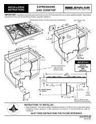
Make Gas Connection<br />
5. Use a ¹⁵⁄₁₆" combination wrench and an adjustable wrench to<br />
attach the flexible connector to the adapters. Check that<br />
connector is not kinked.<br />
A<br />
B<br />
C<br />
D<br />
Explosion Hazard<br />
Use a new CSA International approved gas supply line.<br />
Install a shut-off valve.<br />
Securely tighten all gas connections.<br />
If connected to LP, have a qualified person make sure<br />
gas pressure does not exceed 14" (36 cm) water<br />
column.<br />
Examples of a qualified person include:<br />
licensed heating personnel,<br />
authorized gas company personnel, and<br />
authorized service personnel.<br />
Failure to do so can result in death, explosion, or fire.<br />
A. Gas pressure regulator<br />
B. Use pipe-joint compound.<br />
C. Adapter (must have ½" male<br />
pipe thread)<br />
D. Flexible connector<br />
6. Gas supply pipe must not be more than 10" (25.4 cm) above<br />
the floor.<br />
H<br />
G<br />
E<br />
F<br />
E. Manual gas shutoff valve<br />
F. ½" or ¾" gas pipe<br />
G. Use pipe-joint compound.<br />
H. Adapter<br />
Typical flexible connection<br />
1. Open access panel by grasping sides and pulling upward,<br />
lifting out.<br />
2. Locate gas pressure regulator behind access panel.<br />
C<br />
A<br />
B<br />
A<br />
A. Gas pressure regulator<br />
3. Apply pipe-joint compound made for use with LP gas to the<br />
smaller thread ends of the flexible connector adapters (see B<br />
and G in the following illustration).<br />
4. Attach one adapter to the gas pressure regulator and the<br />
other adapter to the gas shutoff valve. Tighten both adapters.<br />
A. Flexible connector<br />
B. Manual shutoff valve<br />
C. 10" (25.4 cm) max. straight pipe<br />
Complete Connection<br />
1. Open the manual shutoff valve in the gas supply line. The<br />
valve is open when the handle is parallel to the gas pipe.<br />
A<br />
A. Closed valve<br />
B. Open valve<br />
B<br />
2. Test all connections by brushing on an approved<br />
noncorrosive leak-detection solution. If bubbles appear, a<br />
leak is indicated. Correct any leak found.<br />
3. Remove cooktop burner caps and grates from package<br />
containing parts. Align recess in burner caps with pins in<br />
burner base. Burner caps should be level when properly<br />
positioned. If burner caps are not properly positioned,<br />
surface burners will not light. Place burner grates over<br />
burners and caps.<br />
15