INSTALLATION INSTRUCTIONS 30" (76.2 CM) GAS ... - Jenn-Air
INSTALLATION INSTRUCTIONS 30" (76.2 CM) GAS ... - Jenn-Air
INSTALLATION INSTRUCTIONS 30" (76.2 CM) GAS ... - Jenn-Air

You also want an ePaper? Increase the reach of your titles
YUMPU automatically turns print PDFs into web optimized ePapers that Google loves.
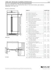
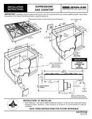
4. Install the Number .038 LP gas oven broil burner orifice hood,<br />
turning it clockwise 4 or 5 turns. Do not overtighten.<br />
.038 A<br />
A. Number .038 LP gas oven broil burner orifice hood<br />
5. Place the oven broil burner on the oven broil burner orifice<br />
hood. Insert the oven broil burner locator pin in the hole in the<br />
oven back.<br />
6. Position the oven broil burner against the roof of the oven<br />
cavity and attach with screw.<br />
A<br />
B<br />
C<br />
D<br />
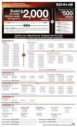
A B C<br />
A. Natural gas orifice spud<br />
B. Dual burner<br />
C. Single burner<br />
Use the following chart for correct LP gas orifice spud for each<br />
burner. Refer to the gas information plate on the right-hand side<br />
of the bottom oven frame for proper sizing of LP gas orifice<br />
spuds for each burner location.<br />
LP Gas Orifice Spud Chart<br />
Location Burner Rating Color Number<br />
Right Front 14,000 BTU Red 114L<br />
Right Rear 4,000 BTU Blue 64L<br />
Left Front 13,000 BTU Center: White<br />
Outer: Orange<br />
Left Rear 9,100 BTU Clear 91L<br />
Center: 55L<br />
Outer: 97L<br />
5. Replace the Natural gas orifice spud with the correct LP gas<br />
orifice spud. See the “LP Gas Orifice Spud Chart.” On dual<br />
burners (on some models), replace the center and outer spuds.<br />
6. Replace burner base and hand tighten the screws.<br />
7. Place LP burner choke into outer hole of dual burner (on<br />
some models).<br />
A. Oven broil burner orifice hood<br />
B. Oven broil burner<br />
C. Oven broil burner locator pin<br />
D. Oven broil burner locator hole<br />
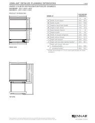
To Convert Surface Burners<br />
A<br />
1. If installed, remove the burner grates.<br />
2. Remove the burner caps.<br />
3. Using a Phillips screwdriver, remove the burner base.<br />
A<br />
B<br />
A. Burner cap<br />
B. Gas tube opening<br />
C. Burner base screws<br />
D. Burner base<br />
4. Apply masking tape to the end of a ⁹⁄₃₂" (7 mm) nut driver to<br />
help hold the Natural gas orifice spud in the nut driver while<br />
changing it. Press nut driver down onto the Natural gas orifice<br />
spud and remove by turning it counterclockwise and lifting<br />
out. Set Natural gas orifice spud aside.<br />
C<br />
D<br />
A. LP burner choke<br />
8. Replace burner cap.<br />
9. Repeat steps 1 through 8 for the remaining burners.<br />
10. Place Natural gas orifice spuds in plastic parts bag for future<br />
use and keep with package containing literature.<br />
11. Replace burner grates.<br />
12. Reinstall oven door. See the “Oven Door” section of the Use<br />
and Care Guide.<br />
13. Plug in range or reconnect power.<br />
14. Complete installation. See “Make Gas Connection” and<br />
“Electronic Ignition System” sections.<br />
Checking for proper cooktop burner flame is very important.<br />
The small inner cone should have a very distinct blue flame<br />
¼" to ½" long. The outer cone is not as distinct as the inner<br />
cone. LP gas flames have a slightly yellow tip.<br />
IMPORTANT: You may have to adjust the “LO” setting for<br />
each cooktop burner.<br />
23