Altivar 21 H - Schneider Electric
Altivar 21 H - Schneider Electric
Altivar 21 H - Schneider Electric

Create successful ePaper yourself
Turn your PDF publications into a flip-book with our unique Google optimized e-Paper software.
Connection diagrams<br />
Connections to meet the requirements of EMC standards<br />
2<br />
Principle<br />
b Grounds between the drive, motor and cable shielding must have<br />
"high-frequency" equipotentiality.<br />
b Use shielded cables with shielding connected to ground throughout<br />
360° at both ends for the motor cable and the control-command<br />
cables. Conduit or metal ducting can be used for part of the shielding<br />
length provided that there is no break in the continuity of the ground<br />
connection.<br />
b Ensure maximum separation between the power supply cable (line supply)<br />
and the motor cable.<br />
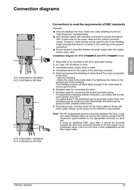
Installation diagram for ATV <strong>21</strong>HpppM3X and ATV <strong>21</strong>HpppN4 drives<br />
1<br />
3 8 6 7 4<br />
ATV <strong>21</strong>H075M3 to HD18M3X,<br />
ATV <strong>21</strong>H075N4 to HD18N4<br />
2<br />
5<br />
1 Steel plate to be mounted on the drive (grounded casing)<br />
2 UL Type 1/IP 20 <strong>Altivar</strong> <strong>21</strong> drive<br />
3 Unshielded power supply wires or cable<br />
4 Unshielded wires for the output of the fault relay contacts<br />
5 Attach and ground the shielding of cables 6 and 7 as close as possible<br />
to the drive:<br />
- Strip the shielding.<br />
- Attach the cable to the metal plate 1 by tightening the clamp on the<br />
stripped part of the shielding.<br />
The shielding must be clamped tightly enough to the metal plate to<br />
ensure good contact.<br />
6 Shielded cable for connecting the motor<br />
7 Shielded cable for connecting the control-command wiring.<br />
For applications requiring several conductors, use cables with a small<br />
cross-section (0.5 mm 2 ).<br />
For cables 6 and 7, the shielding must be grounded at both ends. The<br />
shielding must be continuous and intermediate terminals must be<br />
placed in EMC shielded metal boxes.<br />
8 Grounding screw. Use this screw for the motor cable on drives with<br />
lower power ratings, as the screw on the heatsink is inaccessible.<br />
ENGLISH<br />
8 8<br />
1<br />
5<br />
Note: The HF equipotential ground connection between the drive, motor<br />
and cable shielding does not remove the need to connect the PE<br />
conductors (green-yellow) to the appropriate terminals on each<br />
unit.<br />
If using an additional EMC input filter, it should be mounted<br />
beneath the drive and connected directly to the line supply via an<br />
unshielded cable. Link 3 on the drive is then established via the<br />
filter output cable.<br />
3 6 7 4<br />
ATV <strong>21</strong>HD22M3X, HD30M3X,<br />
ATV <strong>21</strong>HD22N4 to HD75N4<br />
1760794 09/2009 39