Bruciatori di gas ad aria soffiata Gebläse - Gasbrenner Blown type ...
Bruciatori di gas ad aria soffiata Gebläse - Gasbrenner Blown type ...
Bruciatori di gas ad aria soffiata Gebläse - Gasbrenner Blown type ...

You also want an ePaper? Increase the reach of your titles
YUMPU automatically turns print PDFs into web optimized ePapers that Google loves.
Istruzioni per installazione, uso e manutenzione<br />
Anleitungen fŸr Einbau, Betrieb und Wartung<br />
Installation, use and maintenance instructions<br />
Instructions pour installation, utilisation et entretien<br />
I<br />
D<br />
GB<br />
F<br />
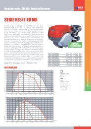
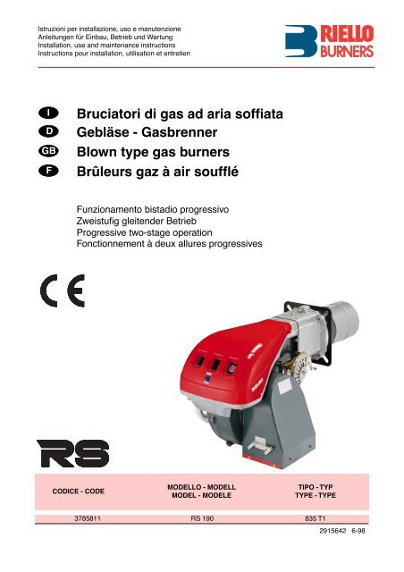
<strong>Bruciatori</strong> <strong>di</strong> <strong>gas</strong> <strong>ad</strong> <strong>aria</strong> sofÞata<br />
GeblŠse - <strong>Gasbrenner</strong><br />
<strong>Blown</strong> <strong>type</strong> <strong>gas</strong> burners<br />
Bržleurs gaz ˆ air soufߎ<br />
Funzionamento bista<strong>di</strong>o progressivo<br />
ZweistuÞg gleitender Betrieb<br />
Progressive two-stage operation<br />
Fonctionnement ˆ deux allures progressives<br />
CODICE - CODE<br />
MODELLO - MODELL<br />
MODEL - MODELE<br />
TIPO - TYP<br />
TYPE - TYPE<br />
3785811 RS 190 835 T1<br />
2915642 6-98
3<br />
INDICE<br />
DATI TECNICI . . . . . . . . . . . . . . . . . . . . . . . . . . . . . . . . . pagina 4<br />
Accessori . . . . . . . . . . . . . . . . . . . . . . . . . . . . . . . . . . . . . . . . . . . 4<br />
Descrizione bruciatore . . . . . . . . . . . . . . . . . . . . . . . . . . . . . . . . . 8<br />
Imballo - Peso. . . . . . . . . . . . . . . . . . . . . . . . . . . . . . . . . . . . . . . . 8<br />
Ingombro . . . . . . . . . . . . . . . . . . . . . . . . . . . . . . . . . . . . . . . . . . . 8<br />
Corredo . . . . . . . . . . . . . . . . . . . . . . . . . . . . . . . . . . . . . . . . . . . . 8<br />
Campo <strong>di</strong> lavoro . . . . . . . . . . . . . . . . . . . . . . . . . . . . . . . . . . . . . 10<br />
Caldaia <strong>di</strong> prova . . . . . . . . . . . . . . . . . . . . . . . . . . . . . . . . . . . . . 10<br />
Caldaie commerciali . . . . . . . . . . . . . . . . . . . . . . . . . . . . . . . . . . 10<br />
Pressione <strong>gas</strong>. . . . . . . . . . . . . . . . . . . . . . . . . . . . . . . . . . . . . . . 12<br />
INSTALLAZIONE. . . . . . . . . . . . . . . . . . . . . . . . . . . . . . . . . . . . 14<br />
Piastra caldaia . . . . . . . . . . . . . . . . . . . . . . . . . . . . . . . . . . . . . . 14<br />
Lunghezza boccaglio . . . . . . . . . . . . . . . . . . . . . . . . . . . . . . . . . 14<br />
Fissaggio del bruciatore alla caldaia . . . . . . . . . . . . . . . . . . . . . 14<br />
Regolazione testa <strong>di</strong> combustione . . . . . . . . . . . . . . . . . . . . . . . 16<br />
Linea alimentazione <strong>gas</strong>. . . . . . . . . . . . . . . . . . . . . . . . . . . . . . . 18<br />
Impianto elettrico . . . . . . . . . . . . . . . . . . . . . . . . . . . . . . . . . . . . 20<br />
Regolazioni prima dellÕaccensione. . . . . . . . . . . . . . . . . . . . . . . 26<br />
Servomotore. . . . . . . . . . . . . . . . . . . . . . . . . . . . . . . . . . . . . . . . 26<br />
Avviamento bruciatore . . . . . . . . . . . . . . . . . . . . . . . . . . . . . . . . 26<br />
Accensione bruciatore . . . . . . . . . . . . . . . . . . . . . . . . . . . . . . . . 26<br />
Regolazione bruciatore: . . . . . . . . . . . . . . . . . . . . . . . . . . . . . . . 28<br />
1 - Potenza allÕaccensione . . . . . . . . . . . . . . . . . . . . . . . . . . . . . 28<br />
2 - Potenza in 2° sta<strong>di</strong>o . . . . . . . . . . . . . . . . . . . . . . . . . . . . . . . 28<br />
3 - Potenza in 1° sta<strong>di</strong>o . . . . . . . . . . . . . . . . . . . . . . . . . . . . . . . 30<br />
4 - Potenze interme<strong>di</strong>e . . . . . . . . . . . . . . . . . . . . . . . . . . . . . . . . 30<br />
5 - Pressostato <strong>aria</strong> . . . . . . . . . . . . . . . . . . . . . . . . . . . . . . . . . . 32<br />
6 - Pressostato <strong>gas</strong> <strong>di</strong> minima . . . . . . . . . . . . . . . . . . . . . . . . . . 32<br />
Controllo presenza Þamma . . . . . . . . . . . . . . . . . . . . . . . . . . . . 32<br />
Funzionamento bruciatore . . . . . . . . . . . . . . . . . . . . . . . . . . . . . 34<br />
Controlli Þnali . . . . . . . . . . . . . . . . . . . . . . . . . . . . . . . . . . . . . . . 36<br />
Manutenzione. . . . . . . . . . . . . . . . . . . . . . . . . . . . . . . . . . . . . . . 36<br />
STATUS . . . . . . . . . . . . . . . . . . . . . . . . . . . . . . . . . . . . . . . . . . . 38<br />
Inconvenienti - Cause - Rime<strong>di</strong> . . . . . . . . . . . . . . . . . . . . . . . . . 40<br />
Avvertenza<br />
Le Þgure richiamate nel testo sono cos“ in<strong>di</strong>cate:<br />
1)(A)<br />
=Particolare 1 della Þgura A nella stessa pagina del testo;<br />
1)(A)p.4 =Particolare 1 della Þgura A riportata a pagina 4.<br />
I<br />
INHALT<br />
TECHNISCHE ANGABEN . . . . . . . . . . . . . . . . . . . . . . . . . Seite 5<br />
Zubehšr. . . . . . . . . . . . . . . . . . . . . . . . . . . . . . . . . . . . . . . . . . . . . 5<br />
Brennerbeschreibung . . . . . . . . . . . . . . . . . . . . . . . . . . . . . . . . . . 9<br />
Verpackung - Gewicht . . . . . . . . . . . . . . . . . . . . . . . . . . . . . . . . . . 9<br />
Abmessungen . . . . . . . . . . . . . . . . . . . . . . . . . . . . . . . . . . . . . . . . 9<br />
Ausstattung . . . . . . . . . . . . . . . . . . . . . . . . . . . . . . . . . . . . . . . . . . 9<br />
Regelbereich . . . . . . . . . . . . . . . . . . . . . . . . . . . . . . . . . . . . . . . . 11<br />
PrŸfkessel . . . . . . . . . . . . . . . . . . . . . . . . . . . . . . . . . . . . . . . . . . 11<br />
HandelsŸbliche Kessel . . . . . . . . . . . . . . . . . . . . . . . . . . . . . . . . 11<br />
Gasdruck. . . . . . . . . . . . . . . . . . . . . . . . . . . . . . . . . . . . . . . . . . . 13<br />
INSTALLATION . . . . . . . . . . . . . . . . . . . . . . . . . . . . . . . . . . . . . 15<br />
Kesselplatte. . . . . . . . . . . . . . . . . . . . . . . . . . . . . . . . . . . . . . . . . 15<br />
FlammrohrlŠnge . . . . . . . . . . . . . . . . . . . . . . . . . . . . . . . . . . . . . 15<br />
Befestigung des Brenners am Heizkessel. . . . . . . . . . . . . . . . . . 15<br />
Einstellung des Flammkopfs . . . . . . . . . . . . . . . . . . . . . . . . . . . . 17<br />
Gaszuleitung . . . . . . . . . . . . . . . . . . . . . . . . . . . . . . . . . . . . . . . . 19<br />
Elektroanlage . . . . . . . . . . . . . . . . . . . . . . . . . . . . . . . . . . . . . . . 21<br />
Einstellungen vor der ZŸndung . . . . . . . . . . . . . . . . . . . . . . . . . . 27<br />
Stellantrieb . . . . . . . . . . . . . . . . . . . . . . . . . . . . . . . . . . . . . . . . . 27<br />
Anfahren des Brenners . . . . . . . . . . . . . . . . . . . . . . . . . . . . . . . . 27<br />
ZŸndung des Brenners . . . . . . . . . . . . . . . . . . . . . . . . . . . . . . . . 27<br />
Brennereinstellung: . . . . . . . . . . . . . . . . . . . . . . . . . . . . . . . . . . . 29<br />
1 - ZŸndleistung . . . . . . . . . . . . . . . . . . . . . . . . . . . . . . . . . . . . . 29<br />
2 - Leistung auf 2. Stufe . . . . . . . . . . . . . . . . . . . . . . . . . . . . . . . 29<br />
3 - Leistung auf 1. Stufe . . . . . . . . . . . . . . . . . . . . . . . . . . . . . . . 31<br />
4 - Zwischenleistungen . . . . . . . . . . . . . . . . . . . . . . . . . . . . . . . . 31<br />
5 - Luft-DruckwŠchter . . . . . . . . . . . . . . . . . . . . . . . . . . . . . . . . . 33<br />
6 - Gas-MindestdruckwŠchter . . . . . . . . . . . . . . . . . . . . . . . . . . . 33<br />
FlammenŸberwachung . . . . . . . . . . . . . . . . . . . . . . . . . . . . . . . . 33<br />
Brennerbetrieb . . . . . . . . . . . . . . . . . . . . . . . . . . . . . . . . . . . . . . 35<br />
Endkontrollen . . . . . . . . . . . . . . . . . . . . . . . . . . . . . . . . . . . . . . . 37<br />
Wartung. . . . . . . . . . . . . . . . . . . . . . . . . . . . . . . . . . . . . . . . . . . . 37<br />
STATUS. . . . . . . . . . . . . . . . . . . . . . . . . . . . . . . . . . . . . . . . . . . . 39<br />
Stšrungen - Ursachen - Abhilfen. . . . . . . . . . . . . . . . . . . . . . . . . 41<br />
Anmerkung<br />
Die Zeichnungen, auf <strong>di</strong>e im Text Bezug genommen wird, werden<br />
folgenderma§en bezeichnet:<br />
1)(A)<br />
=Detail 1 der Zeichnung A auf der gleichen Textseite;<br />
1)(A)p.4 =Detail 1 der Zeichnung A auf Seite 4.<br />
D<br />
CONTENTS<br />
TECHNICAL DATA . . . . . . . . . . . . . . . . . . . . . . . . . . . . . . page 6<br />
Accessories . . . . . . . . . . . . . . . . . . . . . . . . . . . . . . . . . . . . . . . . . 6<br />
Burner description . . . . . . . . . . . . . . . . . . . . . . . . . . . . . . . . . . . . 9<br />
Packaging - Weight. . . . . . . . . . . . . . . . . . . . . . . . . . . . . . . . . . . . 9<br />
Max. <strong>di</strong>mensions. . . . . . . . . . . . . . . . . . . . . . . . . . . . . . . . . . . . . . 9<br />
Standard equipment . . . . . . . . . . . . . . . . . . . . . . . . . . . . . . . . . . . 9<br />
Firing rate . . . . . . . . . . . . . . . . . . . . . . . . . . . . . . . . . . . . . . . . . . 11<br />
Test boiler . . . . . . . . . . . . . . . . . . . . . . . . . . . . . . . . . . . . . . . . . . 11<br />
Commercial boilers. . . . . . . . . . . . . . . . . . . . . . . . . . . . . . . . . . . 11<br />
Gas pressure . . . . . . . . . . . . . . . . . . . . . . . . . . . . . . . . . . . . . . . 13<br />
INSTALLATION . . . . . . . . . . . . . . . . . . . . . . . . . . . . . . . . . . . . . 15<br />
Boiler plate . . . . . . . . . . . . . . . . . . . . . . . . . . . . . . . . . . . . . . . . . 15<br />
Blast tube length . . . . . . . . . . . . . . . . . . . . . . . . . . . . . . . . . . . . 15<br />
Securing the burner to the boiler . . . . . . . . . . . . . . . . . . . . . . . . 15<br />
Combustion he<strong>ad</strong> setting . . . . . . . . . . . . . . . . . . . . . . . . . . . . . . 17<br />
Gas line . . . . . . . . . . . . . . . . . . . . . . . . . . . . . . . . . . . . . . . . . . . 19<br />
Electrical system . . . . . . . . . . . . . . . . . . . . . . . . . . . . . . . . . . . . 21<br />
Adjustments before Þring . . . . . . . . . . . . . . . . . . . . . . . . . . . . . . 27<br />
Servomotor. . . . . . . . . . . . . . . . . . . . . . . . . . . . . . . . . . . . . . . . . 27<br />
Burner starting . . . . . . . . . . . . . . . . . . . . . . . . . . . . . . . . . . . . . . 27<br />
Burner Þring . . . . . . . . . . . . . . . . . . . . . . . . . . . . . . . . . . . . . . . . 27<br />
Burner calibration: . . . . . . . . . . . . . . . . . . . . . . . . . . . . . . . . . . . 29<br />
1 - Firing output . . . . . . . . . . . . . . . . . . . . . . . . . . . . . . . . . . . . . 29<br />
2 - 2nd stage output . . . . . . . . . . . . . . . . . . . . . . . . . . . . . . . . . . 29<br />
3 -1st stage output . . . . . . . . . . . . . . . . . . . . . . . . . . . . . . . . . . . 31<br />
4 - Interme<strong>di</strong>ates outputs . . . . . . . . . . . . . . . . . . . . . . . . . . . . . . 31<br />
5 - Air pressure switch . . . . . . . . . . . . . . . . . . . . . . . . . . . . . . . . 33<br />
6 - Minimum <strong>gas</strong> pressure switch. . . . . . . . . . . . . . . . . . . . . . . . 33<br />
Flame present check . . . . . . . . . . . . . . . . . . . . . . . . . . . . . . . . . 33<br />
Burner operation. . . . . . . . . . . . . . . . . . . . . . . . . . . . . . . . . . . . . 35<br />
Final checks . . . . . . . . . . . . . . . . . . . . . . . . . . . . . . . . . . . . . . . . 37<br />
Maintenance. . . . . . . . . . . . . . . . . . . . . . . . . . . . . . . . . . . . . . . . 37<br />
STATUS . . . . . . . . . . . . . . . . . . . . . . . . . . . . . . . . . . . . . . . . . . . 39<br />
Fault - Probable cause - Suggested remedy . . . . . . . . . . . . . . . 42<br />
N.B.<br />
Figures mentioned in the text are identiÞed as follows:<br />
1)(A)<br />
=part 1 of Þgure A, same page as text;<br />
1)(A)p.4 =part 1 of Þgure A, page number 4.<br />
GB<br />
INDEX<br />
DONNƒES TECHNIQUES . . . . . . . . . . . . . . . . . . . . . . . . . page 7<br />
Accesoires. . . . . . . . . . . . . . . . . . . . . . . . . . . . . . . . . . . . . . . . . . . 7<br />
Description bržleur . . . . . . . . . . . . . . . . . . . . . . . . . . . . . . . . . . . . 9<br />
Emballage - Poids . . . . . . . . . . . . . . . . . . . . . . . . . . . . . . . . . . . . . 9<br />
Encombrement . . . . . . . . . . . . . . . . . . . . . . . . . . . . . . . . . . . . . . . 9<br />
Equipement standard . . . . . . . . . . . . . . . . . . . . . . . . . . . . . . . . . . 9<br />
Plage de puissance. . . . . . . . . . . . . . . . . . . . . . . . . . . . . . . . . . . 11<br />
Chau<strong>di</strong> re dÕessai . . . . . . . . . . . . . . . . . . . . . . . . . . . . . . . . . . . . 11<br />
Chau<strong>di</strong> res commerciales. . . . . . . . . . . . . . . . . . . . . . . . . . . . . . 11<br />
Pression du gaz . . . . . . . . . . . . . . . . . . . . . . . . . . . . . . . . . . . . . 13<br />
INSTALLATION . . . . . . . . . . . . . . . . . . . . . . . . . . . . . . . . . . . . . 15<br />
Plaque chau<strong>di</strong> re . . . . . . . . . . . . . . . . . . . . . . . . . . . . . . . . . . . . 15<br />
Longueur buse . . . . . . . . . . . . . . . . . . . . . . . . . . . . . . . . . . . . . . 15<br />
Fixation du bržleur ˆ la chau<strong>di</strong> re. . . . . . . . . . . . . . . . . . . . . . . . 15<br />
RŽglage t te de combustion . . . . . . . . . . . . . . . . . . . . . . . . . . . . 17<br />
Ligne alimentation gaz . . . . . . . . . . . . . . . . . . . . . . . . . . . . . . . . 19<br />
Installation Žlectrique . . . . . . . . . . . . . . . . . . . . . . . . . . . . . . . . . 21<br />
RŽglages avant lÕallumage . . . . . . . . . . . . . . . . . . . . . . . . . . . . . 27<br />
Servomoteur . . . . . . . . . . . . . . . . . . . . . . . . . . . . . . . . . . . . . . . . 27<br />
DŽmarrage bržleur . . . . . . . . . . . . . . . . . . . . . . . . . . . . . . . . . . . 27<br />
Allumage bržleur . . . . . . . . . . . . . . . . . . . . . . . . . . . . . . . . . . . . . 27<br />
RŽglage bržleur: . . . . . . . . . . . . . . . . . . . . . . . . . . . . . . . . . . . . . 29<br />
1 - Puissance ˆ lÕallumage . . . . . . . . . . . . . . . . . . . . . . . . . . . . . 29<br />
2 - Puissance en 2 me allure . . . . . . . . . . . . . . . . . . . . . . . . . . . 29<br />
3 - Puissance en 1 re allure . . . . . . . . . . . . . . . . . . . . . . . . . . . . 31<br />
4 - Puissances intermŽ<strong>di</strong>ares . . . . . . . . . . . . . . . . . . . . . . . . . . . 31<br />
5 - Pressostat de lÕair . . . . . . . . . . . . . . . . . . . . . . . . . . . . . . . . . 33<br />
6 - Pressostat gaz seuil minimum . . . . . . . . . . . . . . . . . . . . . . . . 33<br />
Contrle prŽsence ßamme . . . . . . . . . . . . . . . . . . . . . . . . . . . . . 33<br />
Fonctionnement bržleur . . . . . . . . . . . . . . . . . . . . . . . . . . . . . . . 35<br />
Contrles Þnaux . . . . . . . . . . . . . . . . . . . . . . . . . . . . . . . . . . . . . 37<br />
Entretien . . . . . . . . . . . . . . . . . . . . . . . . . . . . . . . . . . . . . . . . . . . 37<br />
STATUS. . . . . . . . . . . . . . . . . . . . . . . . . . . . . . . . . . . . . . . . . . . . 39<br />
InconvŽnients - Causes - Rim des . . . . . . . . . . . . . . . . . . . . . . . 43<br />
Attention<br />
Les Þgures rappelŽes dans le texte sont ainsi in<strong>di</strong>quŽes:<br />
1)(A)<br />
=DŽtail 1 de la Þgure A dans la m me page du texte;<br />
1)(A)p.4 =DŽtail 1 de la Þgure A page 4.<br />
F
DATI TECNICI<br />
I<br />
MODELLO RS 190<br />
TIPO<br />
835 T1<br />
POTENZA (1) 2° sta<strong>di</strong>o kW 1279 - 2209<br />
Mcal/h 1100 - 1900<br />
min. 1° sta<strong>di</strong>o kW 470<br />
Mcal/h 405<br />
Potenza max. / Max. pressione in camera <strong>di</strong><br />
combustione con <strong>gas</strong> a pressione nominale:<br />
kW 2209<br />
¥ 20 mbar per G20;<br />
¥ 25 mbar per G25.<br />
mbar 0,8<br />
COMBUSTIBILE<br />
GAS NATURALE: G20 - G21 - G22 - G23 - G25<br />
G20 G25<br />
- potere caloriÞco inferiore kWh/Nm 3<br />
8,6<br />
Mcal/Nm 3 8,6 7,4<br />
- densitˆ assoluta kg/Nm 3 0,71 0,78<br />
- portata massima Nm 3 /h 220 257<br />
- pressione alla portata massima (2) mbar 14 18,2<br />
FUNZIONAMENTO<br />
¥ Intermittente (min. 1 arresto in 24 ore).<br />
¥ Bista<strong>di</strong>o (alta e bassa Þamma) e monosta<strong>di</strong>o (tutto - niente).<br />
IMPIEGO STANDARD<br />
Caldaie: <strong>ad</strong> acqua, a vapore, <strong>ad</strong> olio <strong>di</strong>atermico<br />
TEMPERATURA AMBIENTE °C 0 - 40<br />
TEMPERATURA ARIA COMBURENTE °C max 60<br />
ALIMENTAZIONE ELETTRICA<br />
V<br />
Hz<br />
230 - 400 con neutro ~ +/-10%<br />
50 - trifase<br />
MOTORE ELETTRICO<br />
rpm<br />
W<br />
V<br />
A<br />
2800<br />
4500<br />
220/240 - 380/415<br />
15,8 - 9,1<br />
TRASFORMATORE DÕACCENSIONE<br />
V1 - V2<br />
I1 - I2<br />
230 V - 1 x 8 kV<br />
1 A - 20 mA<br />
POTENZA ELETTRICA ASSORBITA W max 5400<br />
GRADO DI PROTEZIONE IP 44<br />
CONFORMITË DIRETTIVE CEE 90/396 - 89/336 - 73/23<br />
RUMOROSITË (3) dBA 83,1<br />
OMOLOGAZIONE CE 0085AT0042<br />
(1) Con<strong>di</strong>zioni <strong>di</strong> riferimento: Temperatura ambiente 20°C - Pressione barometrica 1000 mbar - Altitu<strong>di</strong>ne 100 m s.l.m.<br />
(2) Pressione alla presa 17)(A)p.8 con pressione zero in camera <strong>di</strong> combustione, con la ghiera del <strong>gas</strong> 2)(B)p.12 aperta ed alla potenza massima<br />
del bruciatore<br />
(3) Pressione sonora misurata nel laboratorio combustione del costruttore, con bruciatore funzionante su caldaia <strong>di</strong> prova, alla potenza massima.<br />
ACCESSORI (su richiesta):<br />
¥ KIT PER FUNZIONAMENTO A GPL.<br />
BRUCIATORE RS 190<br />
POTENZA kW 465 ¸ 2209<br />
CODICE 3010166<br />
¥ RAMPE GAS SECONDO NORMA EN 676 (complete <strong>di</strong> valvole, regolatore <strong>di</strong> pressione e Þltro): vedere a pagina 18.<br />
PAESE<br />
CATEGORIA<br />
IT - AT - GR - DK - FI - SE<br />
II 2H3B/P<br />
ES - GB - IE - PT<br />
II 2H3P<br />
NL<br />
II 2L3B/P<br />
FR<br />
II 2Er3P<br />
DE<br />
II 2ELL3B/P<br />
BE<br />
I 2E(R)B , I 3P<br />
4
TECHNISCHE ANGABEN<br />
D<br />
MODELL RS 190<br />
TYP<br />
835 T1<br />
LEISTUNG (1) 2. Stufe kW 1279 - 2209<br />
Mcal/h 1100 - 1900<br />
min. 1. Stufe kW 470<br />
Mcal/h 405<br />
Hšchstleistung / Hšchstdruck in der Brennkammer mit<br />
Gas bei Nenndruck:<br />
kW 2209<br />
¥ 20 mbar fŸr G20;<br />
¥ 25 mbar fŸr G25.<br />
mbar 0,8<br />
BRENNSTOFF<br />
ERDGAS: G20 - G21 - G22 - G23 - G25<br />
G20 G25<br />
- Unterer Heizwert Hu kWh/Nm 3<br />
Mcal/kg<br />
10<br />
8,6<br />
8,6<br />
7,4<br />
- Rein<strong>di</strong>chte kg/Nm 3 0,71 0,78<br />
- Hšchstdurchsatz Nm 3 /h 220 257<br />
- Druck bei Hšchstdurchsatz (2) mbar 14 18,2<br />
BETRIEB<br />
¥ Aussetzend (min. 1 Halt in 24 Std).<br />
¥ ZweistuÞg (hohe und niedrige Flamme) - einstuÞg (alles - nichts).<br />
STANDARDEINSATZ<br />
Heizkessel: mit Wasser, Dampf, <strong>di</strong>athermischem …l<br />
RAUMTEMPERATUR °C 0 - 40<br />
TEMPERATUR VERBRENNUNGSLUFT °C max 60<br />
ELEKTRISCHE SPEISUNG<br />
V<br />
Hz<br />
230 - 400 mit Nulleiter ~ +/-10%<br />
50 - dreiphasig<br />
ELEKTROMOTOR<br />
rpm<br />
W<br />
V<br />
A<br />
2800<br />
4500<br />
220/240 - 380/415<br />
15,8 - 9,1<br />
Z†NDTRANSFORMATOR<br />
V1 - V2<br />
I1 - I2<br />
230 V - 1 x 8 kV<br />
1 A - 20 mA<br />
ELEKTRISCHE LEISTUNGSAUFNAHME W max 5400<br />
SCHUTZART IP 44<br />
CE-NORMGERECHT 90/396 - 89/336 - 73/23<br />
SCHALLDRUCKPEGEL (3) dBA 83,1<br />
OMOLOGAZIONE CE 0085AT0042<br />
(1) Bezugsbe<strong>di</strong>ngungen: Raumtemperatur 20°C - Barometrischer Druck 1000 mbar - Hšhe 100 m Ÿ.d.M.<br />
(2) Druck am Anschlu§ 17)(A)S.8 bei druckloser Brennkammer, gešffneter Gasscheibe 2)(B)S.12 und bei Hšchstleistung des Brenners<br />
(3) Schalldruck, im BrennprŸßabor des Herstellers mit Brenner auf PrŸfkessel bei Hšchstleistung.<br />
ZUBEH…R (auf Wunsch):<br />
¥ KIT F†R FL†SSIGGAS-BETRIEB.<br />
BRENNER RS 190<br />
LEISTUNG kW 465 ¸ 2209<br />
CODE 3010166<br />
¥ GASARMATUREN GEM€§ NORM EN 676 (mit Ventilen, Druckregler und Filter): siehe Seite 18.<br />
LAND<br />
KATEGORIE<br />
IT - AT - GR - DK - FI - SE<br />
II 2H3B/P<br />
ES - GB - IE - PT<br />
II 2H3P<br />
NL<br />
II 2L3B/P<br />
FR<br />
II 2Er3P<br />
DE<br />
II 2ELL3B/P<br />
BE<br />
I 2E(R)B , I 3P<br />
5
TECHNICAL DATA<br />
GB<br />
MODEL RS 190<br />
TYP<br />
835 T1<br />
OUTPUT (1) 2nd stage kW 1279 - 2209<br />
Mcal/h 1100 - 1900<br />
min. 1st stage kW 470<br />
Mcal/h 405<br />
Max. output / max. pressure in combustion chamber with<br />
<strong>gas</strong> at nominal pressure:<br />
kW 2209<br />
¥ 20 mbar for G20;<br />
¥ 25 mbar for G25.<br />
mbar 0,8<br />
FUEL<br />
NATURAL GAS: G20 - G21 - G22 - G23 - G25<br />
G20 G25<br />
- net caloriÞc value kWh/Nm 3<br />
8.6<br />
Mcal/Nm 3 8.6 7.4<br />
- absolute density kg/Nm 3 0.71 0.78<br />
- max. delivery Nm 3 /h 220 257<br />
- pressure at max. delivery mbar 14 18.2<br />
OPERATION<br />
¥ On-Off (1 stop min each 24 hours).<br />
¥ Two-stage (high and low ßame) and single stage (all - nothing)<br />
STANDARD APPLICATIONS<br />
Boilers: water, steam, <strong>di</strong>athermic oil<br />
AMBIENT TEMPERATUR °C 0 - 40<br />
COMBUSTION AIR TEMPERATURE °C max 60<br />
ELECTRICAL SUPPLY<br />
V<br />
Hz<br />
230 - 400 with neutral ~ +/-10%<br />
50 - three-phaes<br />
ELECTRIC MOTOR<br />
rpm<br />
W<br />
V<br />
A<br />
2800<br />
4500<br />
220/240 - 380/415<br />
15.8 - 9.1<br />
IGNITION TRANSFORMER<br />
V1 - V2<br />
I1 - I2<br />
230 V - 1 x 8 kV<br />
1 A - 20 mA<br />
ELECTRICAL POWER CONSUMPTION W max 5400<br />
ELECTRICAL PROTECTION IP 44<br />
IN CONFORMITY WITH EEC DIRECTIVES 90/396 - 89/336 - 73/23<br />
NOISE LEVELS (2) dBA 83.1<br />
APPROVAL CE 0085AT0042<br />
(1) Reference con<strong>di</strong>tions: Ambient temperature 20°C - Barometric pressure 1000 mbar - Altitude 100 m s.l.m.<br />
(2) Pressure at test point 17)(A)p.8, with zero pressure in the combustion chambre, with open <strong>gas</strong> ring 2)(B)p.12 an maximum burner output<br />
(2) Sound pressure measured in manufacturerÕs combustion laboratory, with burner operating on test boiler and at maximum rated output.<br />
ACCESSORIES (optional):<br />
¥ KIT FOR LPG OPERATION<br />
BURNER RS 190<br />
OUTPUT kW 465 ¸ 2209<br />
CODE 3010166<br />
¥ GAS TRAIN ACCORDING TO REGULATION EN 676 (with valve, pressure governor and Þlter): see page 18.<br />
COUNTRY<br />
CATEGORY<br />
IT - AT - GR - DK - FI - SE<br />
II 2H3B/P<br />
ES - GB - IE - PT<br />
II 2H3P<br />
NL<br />
II 2L3B/P<br />
FR<br />
II 2Er3P<br />
DE<br />
II 2ELL3B/P<br />
BE<br />
I 2E(R)B , I 3P<br />
6
DONNES TECHNIQUES<br />
F<br />
MODELE RS 190<br />
TYPE<br />
835 T1<br />
PUISSANCE (1) 2 me allure kW 1279 - 2209<br />
Mcal/h 1100 - 1900<br />
min. 1 re allure kW 470<br />
Mcal/h 405<br />
Puissance max. / Pression max. dans la chambre de<br />
combustion avec gaz ˆ la pression nominale:<br />
kW 2209<br />
¥ 20 mbar pour G20;<br />
¥ 25 mbar pour G25.<br />
mbar 0,8<br />
COMBUSTIBLE<br />
GAZ NATUREL: G20 - G21 - G22 - G23 - G25<br />
G20 G25<br />
- pouvoir caloriÞque infŽrieur kWh/Nm 3<br />
8,6<br />
Mcal/Nm 3 8,6 7,4<br />
- densitŽ absolue kg/Nm 3 0,71 0,78<br />
- pression au dŽbit max. Nm 3 /h 220 257<br />
- pression au dŽbit max. (2) mbar 14 18,2<br />
FONCTIONNEMENT<br />
¥ Intermittent (1 arr t min en 24 heures)<br />
¥ 2 allures (ßamme haute et basse) et une allure (tout - rien)<br />
EMPLOI STANDARD<br />
Chau<strong>di</strong> res ˆ eau, ˆ vapeur, ˆ huile <strong>di</strong>athermique<br />
TEMPERATURE AMBIANTE °C 0 - 40<br />
TEMPERATURE AIR COMBURANT °C max 60<br />
ALIMENTATION ELECTRIQUES<br />
V<br />
Hz<br />
230 - 400 avec neutre ~ +/-10%<br />
50 - triphasŽe<br />
MOTEUR ELECTRIQUE<br />
rpm<br />
W<br />
V<br />
A<br />
2800<br />
4500<br />
220/240 - 380/415<br />
15,8 - 9,1<br />
TRANSFORMATEUR DÕALLUMAGE<br />
V1 - V2<br />
I1 - I2<br />
230 V - 1 x 8 kV<br />
1 A - 20 mA<br />
PUISSANCE ELECTRIQUE ABSORBEE W max 5400<br />
DEGRE DE PROTECTION IP 44<br />
CONFORMƒMENT AUX DIRECTIVES CEE 90/396 - 89/336 - 73/23<br />
NIVEAU DE BRUIT (2) dBA 83,1<br />
HOMOLOGATION CE 0085AT0042<br />
(1) Con<strong>di</strong>tions de rŽfŽrence: TempŽrature ambiante 20°C - Pression baromŽtrique 1000 mbar - Altitude 100 m au-dessus du niveau de la mer.<br />
(2) Pression ˆ la prise 17)(A)p.8, avec une pression nulle dans la chambre de combustion, avec la bague du gaz 2)(B)p.12 ouverte et ˆ la puissance<br />
maximum du bržleur.<br />
(3) Pression acoustique mesurŽe dans le laboratoire combustion du constructeur, le bržleur fonctionnant sur une chau<strong>di</strong> re dÕessai ˆ la puissance<br />
maximum.<br />
ACCESSOIRES (sur demande):<br />
¥ KIT POUR FONCTIONNEMENT AU GPL<br />
BRULEUR RS 190<br />
PUISSANCE kW 465 ¸ 2209<br />
CODE 3010166<br />
¥ RAMPES GAZ SELON LA NORME EN 676 (avec vannes, regulateur de pression et Þltre): voir p. 18.<br />
PAYS<br />
CATEGORIE<br />
IT - AT - GR - DK - FI - SE<br />
II 2H3B/P<br />
ES - GB - IE - PT<br />
II 2H3P<br />
NL<br />
II 2L3B/P<br />
FR<br />
II 2Er3P<br />
DE<br />
II 2ELL3B/P<br />
BE<br />
I 2E(R)B , I 3P<br />
7
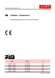
(A)<br />
mm A B C kg<br />
RS 190 1250 725 785 82<br />
(B)<br />
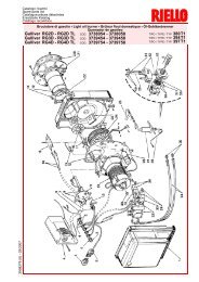
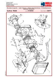
DESCRIZIONE BRUCIATORE (A)<br />
1 Testa <strong>di</strong> combustione<br />
2 Elettrodo <strong>di</strong> accensione<br />
3 Vite per regolazione testa <strong>di</strong> combustione<br />
4 Manicotto<br />
5 Servomotore, comanda la farfalla del <strong>gas</strong> e,<br />
tramite una camma a proÞlo v<strong>aria</strong>bile, la serranda<br />
dellÕ<strong>aria</strong>.<br />
Durante la sosta del bruciatore la serranda<br />
dellÕ<strong>aria</strong> completamente chiusa per ridurre<br />
al minimo le <strong>di</strong>spersioni termiche della caldaia<br />
dovute al tiraggio del camino che<br />
richiama lÕ<strong>aria</strong> dalla bocca <strong>di</strong> aspirazione del<br />
ventilatore<br />
6 Spina-presa sul cavo della sonda <strong>di</strong> ionizzazione<br />
7 Prolunghe per guide 16)<br />
8 Contattore motore e rel termico con pulsante<br />
<strong>di</strong> sblocco<br />
9 STATUS<br />
10 Morsettiera<br />
11 Passacavi per i collegamenti elettrici a cura<br />
dellÕinstallatore<br />
12 Due interruttori elettrici:<br />
- uno per Òacceso - spento bruciatoreÓ<br />
- uno per Ò1° - 2° sta<strong>di</strong>oÓ<br />
13 Apparecchiatura elettrica con avvisatore<br />
luminoso <strong>di</strong> blocco e pulsante <strong>di</strong> sblocco<br />
14 Visore Þamma<br />
15 Pressostato <strong>aria</strong> <strong>di</strong> minima<br />
(tipo <strong>di</strong>fferenziale)<br />
16 Guide per apertura bruciatore ed ispezione<br />
alla testa <strong>di</strong> combustione<br />
17 Presa <strong>di</strong> pressione <strong>gas</strong> e vite Þssa testa<br />
18 Presa <strong>di</strong> pressione <strong>aria</strong><br />
19 Sonda per il controllo presenza Þamma<br />
20 Serranda <strong>aria</strong><br />
21 Ingresso <strong>aria</strong> nel ventilatore<br />
22 Viti per il Þssaggio ventilatore al manicotto<br />
23 Condotto arrivo <strong>gas</strong><br />
24 Valvola farfalla <strong>gas</strong><br />
25 Flangia per il Þssaggio alla caldaia<br />
26 Disco <strong>di</strong> stabilitˆ Þamma<br />
Vi sono due possibilitˆ <strong>di</strong> blocco del bruciatore:<br />
Blocco apparecchiatura: lÕaccensione del pulsante<br />
dellÕapparecchiatura 13)(A) avverte che il<br />
bruciatore in blocco.<br />
Per sbloccare premere il pulsante.<br />
Blocco motore: per sbloccare premere il pulsante<br />
del rel termico 8)(A).<br />
IMBALLO - PESO (B) - misure in<strong>di</strong>cative<br />
¥ LÕ imballo del bruciatore appoggia su una<br />
pedana in legno particolarmente <strong>ad</strong>atta ai carrelli<br />
elevatori. Le <strong>di</strong>mensioni <strong>di</strong> ingombro<br />
dell'imballo sono riportate nella tabella (B).<br />
¥ Il peso del bruciatore completo <strong>di</strong> imballo<br />
in<strong>di</strong>cato nella tabella (B).<br />
INGOMBRO (C) - misure in<strong>di</strong>cative<br />
L'ingombro del bruciatore riportato in Þg. (C).<br />
Tener presente che per ispezionare la testa <strong>di</strong><br />
combustione il bruciatore deve essere aperto<br />
arretrandone la parte posteriore sulle guide.<br />
L'ingombro del bruciatore aperto in<strong>di</strong>cato dalla<br />
quota I.<br />
mm A B C D E F G H I L M N O<br />
RS 190 681 366 315 555 856 372 222 430 1312 230 150 186 DN80<br />
(C)<br />
CORREDO<br />
1 - Flangia per rampa <strong>gas</strong><br />
1 - Guarnizione per ßangia<br />
4 - Viti per Þssare la ßangia M 10 x 35<br />
1 - Schermo termico<br />
4 - Viti per Þssare la ßangia del bruciatore alla<br />
caldaia: M 12 x 35<br />
1 - Istruzione<br />
1 - Catalogo ricambi<br />
8
BRENNERBESCHREIBUNG (A)<br />
1 Flammkopf<br />
2 ZŸndelektrode<br />
3 Einstellschraube des Flammkopfes<br />
4 Gasanschlu§-Muffe<br />
5 Stellantrieb zur Steuerung der Gasdrossel<br />
und, Ÿber einen Nocken mit v<strong>aria</strong>blem ProÞl,<br />
der Luftklappe.<br />
Bei Brennerstillstand ist <strong>di</strong>e Luftklappe<br />
geschlossen, um <strong>di</strong>e WŠrmeverluste des<br />
Kessels durch den Kaminzug mit LuftnachfŸhrung<br />
von der Saugšffnung des GeblŠses<br />
zu vermeiden<br />
6 Steckanschlu§ am Kabel der Ionisationssonde<br />
7 VerlŠngerungen zu Gleitschienen 16)<br />
8 MotorschŸtz und †berstromauslšser mit Entriegelungsschalter<br />
9 STATUS<br />
10 Klemmenbrett<br />
11 KabeldurchgŠnge fŸr <strong>di</strong>e ElektroanschlŸsse<br />
vom Installateur<br />
12 Zwei Schalter:<br />
- einer fŸr ÒBrenner eingeschaltet-ausgeschaltetÓ<br />
- einer fŸr Ò1. - 2. StufeÓ<br />
13 SteuergerŠt mit Kontrollampe fŸr Stšrabschaltung<br />
und Entriegelungsschalter<br />
14 Flammen-Sichtfenster<br />
15 MindestluftdruckwŠchter<br />
(Differentialtyp)<br />
16 Gleitschienen zur …ffnung des Brenners und<br />
fŸr <strong>di</strong>e Kontrolle des Flammkopfs<br />
17 Gasdruckentnahmestelle und Befestigungsschraube<br />
des Flammkopfes<br />
18 Luftdruckentnahmestelle<br />
19 FlammenfŸhler<br />
20 Luftklappe<br />
21 Lufteinla§ zum GeblŠse<br />
22 Befestigungsschraube des GeblŠses an der<br />
Gasanschlu§-Muffe<br />
23 Gaszuleitung<br />
24 Gasdrossel<br />
25 Befestigungsßansch am Kessel<br />
26 Stauscheibe<br />
Die Stšrabschaltungen des Brenners kšnnen<br />
zweierlei Art sein:<br />
Stšrabschaltung des GerŠtes: Das Außeuchten<br />
des Druckknopfes des GerŠtes 13)(A) weist auf<br />
eine Stšrabschaltung des Brenners hin.<br />
Zur Entriegelung den Druckknopf drŸcken.<br />
Stšrabschaltung des Motors: Entriegelung<br />
durch DrŸkken auf den Druckknopf des †berstromauslšsers<br />
8)(A).<br />
VERPACKUNG - GEWICHT (B) - Richtwerte<br />
¥ Der Brenner steht auf einem besonders fŸr<strong>di</strong>e<br />
Handhabung mit Hubwagen geeignetem<br />
Holzrahmen. Die Au§enabmessungen der Verpackung<br />
sind in Tabelle (B) aufgefŸhrt.<br />
¥ Das Gesamtgewicht des Brenners einschlie§lich<br />
Verpackung wird aus Tabelle (B)<br />
ersichtlich (B).<br />
ABMESSUNGEN (C) - Richtwerte<br />
Die Brennerabmessungen sind in der Abb. (C)<br />
angefŸhrt.<br />
Zur Inspektion des Flammkopfes mu§ der Brenner<br />
zurŸckgeschoben und nach oben<br />
geschwenkt werden.<br />
Die Abmessungen des offenen Brenners, ohne<br />
Verkleidung, sind unter I aufgefŸhrt.<br />
AUSSTATTUNG<br />
1 - Flansch fŸr Gasarmaturen<br />
1 - Dichtung fŸr Flansch<br />
4 - Schrauben fŸr <strong>di</strong>e Befestigung des M10 x<br />
35 Flansches<br />
1 - WŠrmeschild<br />
4 - Schrauben fŸr <strong>di</strong>e Befestigung des Brennerßanschs<br />
am Kessel: M 12 x 35<br />
1 - Anleitung<br />
1 - Ersatzteile Katalog<br />
BURNER DESCRIPTION (A)<br />
1 Combustion he<strong>ad</strong><br />
2 Ignition electrode<br />
3 Screw for combustion he<strong>ad</strong> <strong>ad</strong>justment<br />
4 Sleeve<br />
5 Servomotor controlling the <strong>gas</strong> butterßy valve<br />
and of air gate valve (by means of a v<strong>aria</strong>ble<br />
proÞle cam mechanism).<br />
When the burner is not operating the air gate<br />
valve is fully closed in order to reduce heat<br />
<strong>di</strong>spersion from the boiler due to the ßue<br />
draught which draws air from the fan suction<br />
inlet.<br />
6 Plug-socket on ionisation proble cable<br />
7 Extensions for slide bars 16)<br />
8 Motor contactor and thermal cut-out with<br />
reset button<br />
9 STATUS<br />
10 Terminal strip<br />
11 Fairle<strong>ad</strong>s for electrical connections by<br />
installer<br />
12 Two switches:<br />
- one Òburner off-onÓ<br />
- one for Ò1st - 2nd stage operationÓ<br />
13 Control box with lock-out pilot light and lockout<br />
reset button<br />
14 Flame inspection window<br />
15 Minimum air pressure switch<br />
(<strong>di</strong>fferential operating <strong>type</strong>)<br />
16 Slide bars for opening the burner and<br />
inspecting the combustion he<strong>ad</strong><br />
17 Gas pressure test point and he<strong>ad</strong> Þxing<br />
screw<br />
18 Air pressure test point<br />
19 Flame sensor probe<br />
20 Air gate valve<br />
21 Air inlet to fan<br />
22 Screws securing fan to sleeve<br />
23 Gas input pipework<br />
24 Gas butterßy valve<br />
25 Boiler mounting ßange<br />
26 Flame stability <strong>di</strong>sk<br />
Two <strong>type</strong>s of burner failure may occur:<br />
Control Box Lock-out: if the control box 13)(A)<br />
pushbutton lights up, it in<strong>di</strong>cates that the burner<br />
is in lock-out.<br />
To reset, press the pushbutton.<br />
Motor trip: release by pressing the pushbutton<br />
on thermal relay 8)(A).<br />
PACKAGING - WEIGHT (B) - Approximate measurements<br />
¥ The burners stands on a wooden base which<br />
can be lifted by fork-lifts. Outer <strong>di</strong>mensions of<br />
packaging are in<strong>di</strong>cated in (B).<br />
¥ The weight of the burner complete with packaging<br />
is in<strong>di</strong>cated in Table (B).<br />
MAX. DIMENSIONS (C) - Approximate measurements<br />
The maximum <strong>di</strong>mensions of the burner are<br />
given in (C).<br />
Bear in mind that inspection of the combustion<br />
he<strong>ad</strong> requires the burner to be opened and the<br />
rear part withdrawn on the slide bars.<br />
The maximum <strong>di</strong>mension of the burner, without<br />
casing, when open is give by measurement I.<br />
STANDARD EQUIPMENT<br />
1 - Gas train ßange<br />
1 - Flange <strong>gas</strong>ket<br />
4 - Flange Þxing screws M 10 x 35<br />
1 - Thermal insulation screen<br />
4 - Screws to secure the burner ßange to the<br />
boiler: M 12 x 35<br />
1 - Instruction booklet<br />
1 - Spare parts list<br />
DESCRIPTION BRULEUR (A)<br />
1 T te de combustion<br />
2 Electrode d'allumage<br />
3 Vis pour rŽglage t te de combustion<br />
4 Manchon<br />
5 Servomoteur de commande de la vanne<br />
papillon du gaz et, par came ˆ proÞl v<strong>aria</strong>ble,<br />
du volet d'air. Lors de l'arr t du bržleur ce<br />
volet d'air est compl tement fermŽ aÞn de<br />
rŽduire le plus possible les <strong>di</strong>spersions thermiques<br />
de la chau<strong>di</strong> re causŽes par le tirage<br />
du conduit de rappel d'air sur la bouche<br />
d'aspiration du ventilateur.<br />
6 Fiche prise sur c‰ble sonde dÕionisation<br />
7 Rallonges pour guides 16)<br />
8 Contacteur moteur et relais thermique avec<br />
bouton de dŽblocage<br />
9 STATUS<br />
10 Bornier<br />
11 Passe-c‰bles pour les connexions Žlectriques<br />
aux soins de lÕinstallateur<br />
12 Deux interrupteurs Žlectriques:<br />
- un pour bržleur ÒallumŽ - ŽteintÓ<br />
- un pour Ò1 re - 2 me allureÓ<br />
13 Coffret de sŽcuritŽ avec signal lumineux de<br />
blocage et bouton de dŽblocage<br />
14 Viseur ßamme<br />
15 Pressostat air seul minimum<br />
(<strong>type</strong> <strong>di</strong>ffŽrentiel)<br />
16 Guides pour ouverture bržleur et inspection<br />
de la t te de combustion<br />
17 Prise de pression gaz et vis de Þxation t te<br />
18 Prise de pression air<br />
19 Sonde de contrle prŽsence ßamme<br />
20 Volet d'air<br />
21 EntrŽe dÕair dans le ventilateur<br />
22 Vis de Þxation ventilateur au manchon<br />
23 Canalisation dÕarrive du gaz<br />
24 Vanne papillon gaz<br />
25 Bride de Þxation ˆ la chau<strong>di</strong> re<br />
26 Disque de stabilitŽ de la ßamme<br />
Il existe deux <strong>type</strong>s de blocage du bržleur:<br />
Blocage coffret: l'allumage du bouton du coffret<br />
de sŽcuritŽ 13)(A) avertit que le bržleur s'est<br />
bloquŽ.<br />
Pour le dŽbloquer appuyer sur le bouton.<br />
Blocage moteur: pour le dŽbloquer appuyer sur<br />
le bouton-poussoir du relais thermique 8)(A).<br />
EMBALLAGE - POIDS (B) - Mesures in<strong>di</strong>catives<br />
¥ Le bržleur est placŽ sur une palette qui peut<br />
tre soulevŽe par des chariots transpalettes.<br />
Les <strong>di</strong>mensions dÕencombrement de lÕemballage<br />
sont reportŽes dans le tableau (B).<br />
¥ Le poids du bržleur avec son emballage est<br />
in<strong>di</strong>quŽ dans le tab. (B).<br />
ENCOMBREMENT (C) - Mesures in<strong>di</strong>catives<br />
L'encombrement du bržleur est in<strong>di</strong>quŽ dans le<br />
tab. (C).<br />
Il faut tenir compte du fait que pour inspecter la<br />
t te de combustion, le bržleur doit tre ouvert, la<br />
partie arri re reculŽe sur les guides. L'encombrement<br />
du bržleur ouvert, sans carter, est in<strong>di</strong>quŽ<br />
par la cote I.<br />
EQUIPEMENT STANDARD<br />
1 - Bride pour rampe gaz<br />
1 - Joint pour bride<br />
4 - Vis de Þxation bride M 10 x 35<br />
1 - Ecran thermique<br />
4 - Vis pour Þxer la bride du bržleur ˆ la chau<strong>di</strong><br />
re: M 12 x 35<br />
1 - Instructions<br />
1 - Catalogue pi ces dŽtachŽes<br />
9
CAM. COMB. / FEUERRAUM m<br />
COMB. CHAMBER / CHAMB. COMB. CAM. COMB. / FEUERRAUM mbar<br />
(A)<br />
COMB. CHAMBER / CHAMB. COMB.<br />
CAMPO DI LAVORO (A)<br />
Il bruciatore RS 190 pu˜ funzionare in due mo<strong>di</strong>:<br />
monosta<strong>di</strong>o o bista<strong>di</strong>o.<br />
La POTENZA MASSIMA va scelta entro lÕ area A.<br />
La POTENZA MINIMA non deve essere inferiore<br />
al limite minimo del <strong>di</strong>agramma:<br />
RS 190 = 470 kW<br />
Attenzione:<br />
il CAMPO DI LAVORO stato ricavato alla temperatura<br />
ambiente <strong>di</strong> 20 °C, alla pressione barometrica<br />
<strong>di</strong> 1000 mbar (circa 100 m s.l.m.) e con<br />
la testa <strong>di</strong> combustione regolata come in<strong>di</strong>cato a<br />
p. 16.<br />
CALDAIA DI PROVA (B)<br />
I campi <strong>di</strong> lavoro sono stati ricavati in speciali<br />
caldaie <strong>di</strong> prova, secondo la norma EN 676.<br />
Riportiamo in (B) <strong>di</strong>ametro e lunghezza della<br />
camera <strong>di</strong> combustione <strong>di</strong> prova.<br />
Esempio: Potenza 650 Mcal/h:<br />
<strong>di</strong>ametro 60 cm - lunghezza 2 m.<br />
CALDAIE COMMERCIALI (C)<br />
LÕabbinamento bruciatore-caldaia non pone problemi<br />
se la caldaia omologata CE e le <strong>di</strong>mensioni<br />
della sua camera <strong>di</strong> combustione sono<br />
vicine a quelle in<strong>di</strong>cate dal <strong>di</strong>agramma (B).<br />
Se invece il bruciatore deve essere applicato <strong>ad</strong><br />
una caldaia commerciale non omologata CE e/o<br />
con <strong>di</strong>mensioni della camera <strong>di</strong> combustione<br />
nettamente pi piccole <strong>di</strong> quelle in<strong>di</strong>cate dal <strong>di</strong>agramma<br />
(B), consultare i costruttori.<br />
(B)<br />
10
REGELBEREICH (A)<br />
Die Brenner RS 190 kann auf zwei Arten funktionieren:<br />
ein - oder zweistuÞg.<br />
Die H…CHSTLEISTUNG wird innerhalb des<br />
Felds A gewŠhlt.<br />
Die MINDESTLEISTUNG soll nicht niedriger<br />
sein als <strong>di</strong>e Mindestgrenze des Diagramms.<br />
RS 190 = 470 kW<br />
Achtung:<br />
der REGELBEREICH wurde bei einer Raumtemperatur<br />
von 20 °C, einem barometrischen<br />
Druck von 1000 mbar (ungefŠhr 100 m Ÿ.d.M.)<br />
und einem wie auf Seite 17 eingestelltem<br />
Flammkopf gemessen.<br />
PR†FKESSEL (B)<br />
Die Regelbereiche wurden an speziellen PrŸfkesseln<br />
entsprechend Norm EN 676 ermittelt.<br />
In (B) sind Durchmesser und LŠnge der PrŸf-<br />
Brennkammer angegeben.<br />
Beispiel:<br />
Leistung 650 Mcal/h:<br />
Durchmesser = 60 cm, LŠnge = 2 m.<br />
HANDELS†BLICHE KESSEL (C)<br />
Die Brenner-Kessel Kombination gibt keine Probleme,<br />
falls der Kessel "CE" - typgeprŸft ist und<br />
<strong>di</strong>e Abmessungen seiner Brennkammer sich<br />
den im Diagramm (B) angegebenen nŠhern.<br />
Falls der Brenner dagegen an einem handelsŸblichen<br />
Kessel angebracht werden mu§, der nicht<br />
"CE"-typgeprŸft ist und/oder mit Abmessungen<br />
der Brennkammer, <strong>di</strong>e entschieden kleiner als<br />
jene in Diagramm (B) angegebenen sind, sollte<br />
der Hersteller zu Rate gezogen werden.<br />
FIRING RATE (A)<br />
The RS 190 model burner can work in two way:<br />
one-stage and two-stage.<br />
MAXIMUM OUTPUT must be selected in area<br />
A.<br />
MINIMUM OUTPUT must not be lower than the<br />
minimum limit shown in the <strong>di</strong>agram.<br />
RS 190 = 470 kW<br />
Important:<br />
The FIRING RATE area values have been<br />
obtained considering a surroun<strong>di</strong>ng temperature<br />
of 20 °C, and an atmospheric pressure of 1000<br />
mbar (approx. 100 m above sea level) and with<br />
the combustion he<strong>ad</strong> <strong>ad</strong>justed as shown on<br />
page 17.<br />
TEST BOILER (B)<br />
The Þring rates were set in relation to special<br />
test boilers, accor<strong>di</strong>ng to EN 676 regulations.<br />
Figure (B) in<strong>di</strong>cates the <strong>di</strong>ameter and length of<br />
the test combustion chamber.<br />
Example:<br />
Output 650 Mcal/h:<br />
<strong>di</strong>ameter = 60 cm; length<br />
COMMERCIAL BOILERS (C)<br />
The burner/boiler combination does not pose<br />
any problems if the boiler is CE <strong>type</strong>-approved<br />
and its combustion chamber <strong>di</strong>mensions are<br />
similar to those in<strong>di</strong>cated in <strong>di</strong>agram (B).<br />
If the burner must be combined with a commercial<br />
boiler that has not been Ce <strong>type</strong>-approved<br />
and/or its combustion chamber <strong>di</strong>mensions are<br />
clearly smaller than those in<strong>di</strong>cated in <strong>di</strong>agram<br />
(B), consult the manufacturer.<br />
PLAGE DE PUISSANCE (A)<br />
Le bržleur RS 190 peut fonctionner de deux<br />
fa ons: ˆ une allure ou ˆ deux allures.<br />
La PUISSANCE MAXIMUM doit tre choisie<br />
dans la plage A.<br />
La PUISSANCE MINIMUM ne doit pas tre infŽrieure<br />
ˆ la limite minimum du <strong>di</strong>agramme.<br />
RS 190 = 470 kW<br />
Attention:<br />
La PLAGE DE PUISSANCE a ŽtŽ calculŽe ˆ<br />
une tempŽrature ambiante de 20 °C, ˆ une<br />
pression baromŽtrique de 1000 mbars (environ<br />
100 m au-dessus du niveau de la mer) et avec<br />
la t te de combustion rŽglŽe comme in<strong>di</strong>que la<br />
p. 17.<br />
CHAUDIERE DÕESSAI (B)<br />
Les plages de puissance ont ŽtŽ Žtablies sur<br />
des chaiui res dÕessai spŽciales, selon la norme<br />
EN 676. Nous reportons Þg.(B) le <strong>di</strong>am tre et la<br />
longueur de la chambre de combustion dÕessai.<br />
Exempe:<br />
Puissance 650 Mcal/h:<br />
<strong>di</strong>am tre 60 cm - longueur 2 m.<br />
CHAUDIERES COMMERCIALES (C)<br />
LÕaccouplement bržleur-chau<strong>di</strong> re ne pose<br />
aucun probl me si la chau<strong>di</strong> re est homologuŽe<br />
CE et si les <strong>di</strong>mensions de sa chambre de combustion<br />
sont proches de celles in<strong>di</strong>quŽes dans<br />
le <strong>di</strong>agramme (B).<br />
Par contre, si le bržleur doit tre accouplŽ ˆ une<br />
chau<strong>di</strong> re commerciale non homologuŽe CE,<br />
et/ou avec des <strong>di</strong>mensions de chambre de combustion<br />
plus petites que celles in<strong>di</strong>quŽes dans le<br />
<strong>di</strong>agramme (B), consulter le constructeur.<br />
11
RS 190<br />
Dp (mbar)<br />
3<br />
kW 1 2<br />
¯ 2Ó ¯ DN65 ¯ DN80 ¯ DN100<br />
1280 7,0 1,8 30,0 11,0 5,6 -<br />
1400 7,3 2,0 35,0 15,0 7,0 -<br />
1500 7,6 2,2 40,0 16,0 8,0 -<br />
1600 8,0 2,5 45,0 17,0 9,0 4,5<br />
1700 8,7 2,8 52,0 19,0 10,0 4,7<br />
1800 9,3 3,0 58,0 21,0 11,0 5,0<br />
1900 10,2 3,2 63,0 23,0 12,0 5,8<br />
2000 11,3 3,4 68,0 25,0 13,0 6,1<br />
2100 12,5 3,7 74,0 27,5 14,0 6,8<br />
2209 14,0 4,0 84,0 31,0 16,0 7,5<br />
(A)<br />
(B)<br />
PRESSIONE GAS<br />
Le tabelle a lato in<strong>di</strong>cano le per<strong>di</strong>te <strong>di</strong> carico<br />
minime lungo la linea <strong>di</strong> alimentazione del <strong>gas</strong> in<br />
funzione della potenza del bruciatore in 2° sta<strong>di</strong>o.<br />
Colonna 1<br />
Per<strong>di</strong>ta <strong>di</strong> carico testa <strong>di</strong> combustione.<br />
Pressione del <strong>gas</strong> misurata alla presa 1)(B),<br />
con:<br />
¥ Camera <strong>di</strong> combustione a 0 mbar;<br />
¥ Bruciatore funzionante in 2° sta<strong>di</strong>o;<br />
¥ Testa <strong>di</strong> combustione regolata come <strong>di</strong>agramma<br />
(C)p. 16.<br />
Colonna 2<br />
Per<strong>di</strong>ta <strong>di</strong> carico farfalla <strong>gas</strong> 2)(B) con apertura<br />
massima: 90°.<br />
Colonna 3<br />
Per<strong>di</strong>ta <strong>di</strong> carico rampa 3)(B) comprendente:<br />
valvola <strong>di</strong> regolazione VR, valvola <strong>di</strong> sicurezza<br />
VS (entrambe con apertura massima), regolatore<br />
<strong>di</strong> pressione R, Þltro F.<br />
I valori riportati nelle tabelle si riferiscono a:<br />
<strong>gas</strong> naturale G 20 PCI 10 kWh/Nm 3 (8,6 Mcal/Nm 3 )<br />
Con:<br />
<strong>gas</strong> naturale G 25 PCI 8,6 kWh/Nm 3 (7,4 Mcal/Nm 3 )<br />
moltiplicare i valori delle tabelle per 1,3.<br />
Per conoscere la potenza approssimativa alla<br />
quale sta funzionando il bruciatore in 2° sta<strong>di</strong>o:<br />
- Sottrarre dalla pressione del <strong>gas</strong> alla presa<br />
1)(B) la pressione in camera <strong>di</strong> combustione.<br />
- Trovare nella tabella (A), colonna 1, il valore<br />
<strong>di</strong> pressione pi vicino al valore desiderato.<br />
- Leggere sulla sinistra la potenza corrispondente.<br />
Esempio:<br />
¥ Funzionamento in 2° sta<strong>di</strong>o<br />
¥ Gas naturale G 20 PCI 10 kWh/Nm 3<br />
¥ Pressione del <strong>gas</strong> alla presa 1)(B) =11,0 mbar<br />
¥ Pressione in camera <strong>di</strong> combustione =3,0 mbar<br />
11,0 - 3,0 =8,0 mbar<br />
Alla pressione 8,0 mbar, colonna 1, corrisponde<br />
nella tabella (A) una potenza in 2° sta<strong>di</strong>o <strong>di</strong><br />
1600 kW.<br />
Questo valore serve come prima approssimazione;<br />
la portata effettiva va misurata al contatore.<br />
Per conoscere invece la pressione del <strong>gas</strong><br />
necess<strong>aria</strong> alla presa 1)(B), Þssata la potenza<br />
alla quale si desidera funzioni il bruciatore in 2°<br />
sta<strong>di</strong>o:<br />
- Trovare nella tabella (A) il valore <strong>di</strong> potenza<br />
pi vicino al valore desiderato.<br />
- Leggere sulla destra, colonna 1, la pressione<br />
alla presa 1)(B).<br />
- Sommare a questo valore la presunta pressione<br />
in camera <strong>di</strong> combustione.<br />
Esempio:<br />
¥ Potenza desiderata in 2° sta<strong>di</strong>o: 1600 kW<br />
¥ Gas naturale G 20 PCI 10 kWh/Nm 3<br />
¥ Pressione del <strong>gas</strong> alla potenza <strong>di</strong> 1600 kW,<br />
dalla tabella (A), colonna 1 =8,0 mbar<br />
¥ Pressione in camera <strong>di</strong> combustione =3,0 mbar<br />
8,0 + 3,0 =11,0 mbar<br />
pressione necess<strong>aria</strong> alla presa 1)(B).<br />
12
GASDRUCK<br />
In den nebenstehenden Tabellen werden <strong>di</strong>e<br />
Mindeststršmungsverluste entlang der Gaszuleitung<br />
in AbhŠngigkeit der Brennerleistung auf<br />
der 2. Stufe angezeigt.<br />
Spalte 1<br />
Stršmungsverlust Flammkopf.<br />
Gasdruck an der Entnahmestelle 1)(B) gemessen,<br />
bei:<br />
¥ Brennkammer auf 0 mbar;<br />
¥ Brennerbetrieb auf der 2. Stufe;<br />
¥ GemŠ§ Diagramm (C)S. 16 eingestellter<br />
Flammkopf.<br />
Spalte 2<br />
Stršmungsverlust Gasdrossel 2)(B) bei maximaler<br />
…ffnung: 90°.<br />
Spalte 3<br />
Stršmungsverlust Armaturen 3)(B) bestehend<br />
aus: Regelventil VR, Sicherheitsventil VS (beide<br />
bei maximaler …ffnung), Druckregler R, Filter F.<br />
Die Tabellenwerte beziehen sich auf:<br />
Erd<strong>gas</strong>-Hu 10 kWh/Nm 3 (8,6 Mcal/Nm 3 )<br />
Bei:<br />
Erd<strong>gas</strong>-Hu 8,6 kWh/Nm 3 (7,4 Mcal/Nm 3 ) e<br />
Tabellenwerte mit 1,3 multiplizieren.<br />
Zur Ermittlung der ungefŠhren Brennerleistung<br />
im Betrieb auf der 2. Stufe:<br />
- Vom Gasdruck an der Entnahmestelle 1)(B)<br />
den Druck in der Brennkammer abziehen.<br />
- In der Tabelle (A), unter Spalte 1, den der<br />
Subtraktion nŠchsten Wert ablesen.<br />
- Die entsprechende Leistung links ablesen.<br />
Beispiel:<br />
¥ Betrieb auf 2. Stufe<br />
¥ Erd<strong>gas</strong> Hu 10 kWh/Nm 3<br />
¥ Gasdruck an der Entnahmestelle 1)(B) =11,0 mbar<br />
¥ Brennkammerdruck =3,0 mbar<br />
11,0 - 3 =8,0 mbar<br />
Dem Druck von 8,0 mbar, Spalte 1, entspricht in<br />
der Tabelle (A) eine Leistung auf der 2. Stufe<br />
von 1600 kW.<br />
Dieser Wert <strong>di</strong>ent als erste NŠherung; der tatsŠchliche<br />
Durchsatz wird am ZŠhler abgelesen.<br />
Zur Ermittlung des fŸr den an der Entnahmestelle<br />
1)(B) erforderlichen Gasdruckes, nachdem<br />
<strong>di</strong>e Brennerleistung auf 2. Stufe festgelegt<br />
wurde:<br />
- In der Tabelle (A) <strong>di</strong>e dem gewŸnschten Wert<br />
nŠchste Leistungsangabe ablesen.<br />
- Rechts, unter der Spalte 1, den Druck an der<br />
Entnahmestelle 1)(B) ablesen.<br />
- Diesen Wert mit dem angenommenen Druck<br />
in der Brennkammer <strong>ad</strong><strong>di</strong>eren.<br />
Esempio:<br />
¥ GewŸnschte Leistung auf 2. Stufe: 1600 kW<br />
¥ Erd<strong>gas</strong> Hu 10 kWh/Nm 3<br />
¥ Gasdruck bei 1600 kW Leistung, aus Tabelle<br />
(A), Spalte 1<br />
=8,0 mbar<br />
¥ Brennkammerdruck =3,0 mbar<br />
8,0 + 3 =11,0 mbar<br />
Erforderlicher Druck an der Entnahmestelle<br />
1)(B).<br />
GAS PRESSURE<br />
The <strong>ad</strong>jacent tables show minimum pressure<br />
losses along the <strong>gas</strong> supply line depen<strong>di</strong>ng on<br />
the burner output in 2nd stage operation.<br />
Column 1<br />
Pressure loss at combustion he<strong>ad</strong>.<br />
Gas pressure measured at test point 1)(B), with:<br />
¥ Combustion chamber at 0 mbar;<br />
¥ Burner operating in 2nd stage;<br />
¥ Combustion he<strong>ad</strong> <strong>ad</strong>justed as in<strong>di</strong>cated in<br />
<strong>di</strong>agram (C)p. 16.<br />
Column 2<br />
Pressure loss at <strong>gas</strong> butterßy valve 2)(B) with<br />
maximum opening: 90°.<br />
Column 3<br />
Pressure loss of <strong>gas</strong> train 3)(B) includes: <strong>ad</strong>justment<br />
valve VR, safety valve VS (both fully open),<br />
pressure governor R, Þlter F.<br />
The values shown in the various tables refer to:<br />
natural <strong>gas</strong> G 20 PCI 10 kWh/Nm 3 (8,6 Mcal/Nm 3 )<br />
With:<br />
natural <strong>gas</strong> G 25 PCI 8,6 kWh/Nm 3 (7,4 Mcal/Nm 3 )<br />
multiply tabulated values by 1,3.<br />
Calculate the approximate 2nd stage output of<br />
the burner thus:<br />
- subtract the combustion chamber pressure<br />
from the <strong>gas</strong> pressure measured at test point<br />
1)(B).<br />
- Find the nearest pressure value to your result<br />
in column 1 of the table (A).<br />
- Re<strong>ad</strong> off the correspon<strong>di</strong>ng output on the left.<br />
Example:<br />
¥ 2nd stage operation<br />
¥ Natural <strong>gas</strong> G 20 PCI 10 kWh/Nm 3<br />
¥ Gas pressure at test point 1)(B) =11,0 mbar<br />
¥ Pressure in combustion chamber =3,0 mbar<br />
11,0 - 3 =8,0 mbar<br />
A 2nd stage output of 1600 kW shown in Table<br />
(A) corresponds to 8,0 mbar pressure, column<br />
1.<br />
This value serves as a rough guide, the effective<br />
delivery must be measured at the <strong>gas</strong> meter.<br />
To calculate the required <strong>gas</strong> pressure at test<br />
point 1)(B), set the output required from the<br />
burner in 2nd stage operation:<br />
- Find the nearest output value in the table (A).<br />
- Re<strong>ad</strong> off the pressure at test point 1)(B) on<br />
the right in column 1.<br />
- Add this value to the estimated pressure in<br />
the combustion chamber.<br />
Example:<br />
¥ Required burner output in 2nd stage operation:<br />
1600 kW<br />
¥ Natural <strong>gas</strong> G 20 PCI 10 kWh/Nm 3<br />
¥ Gas pressure at burner output of 1600 kW,<br />
taken from table (A), column 1 = 8,0 mbar<br />
¥ Pressure in combustion chamber = 3,0 mbar<br />
8,0 + 3 =11,0 mbar<br />
pressure required at test point 1)(B).<br />
PRESSION DU GAZ<br />
Les tableaux ci-contre in<strong>di</strong>quent les pertes de<br />
charge minimales sur la ligne d'alimentation en<br />
gaz en fonction de la puissance du bržleur en<br />
2 me allure.<br />
Colonne 1<br />
Perte de charge t te de combustion.<br />
Pression du gaz mesurŽe ˆ la prise 1)(B), avec:<br />
¥ Chambre de combustion ˆ 0 mbar;<br />
¥ Bržleur fonctionnant en 2 me allure;<br />
¥ T te de combustion rŽglŽe selon le <strong>di</strong>agramme<br />
(C)p. 16.<br />
Colonne 2<br />
Perte de charge vanne papillon gaz 2)(B) avec<br />
ouverture maximum: 90°.<br />
Colonne 3<br />
Perte de charge de la rampe gaz 3)(B) comprenant:<br />
vanne de rŽgulation VR, vanne de sŽcuritŽ<br />
VS (ayant chacune une ouverture maximum),<br />
rŽgulateur de pression R, Þltre F.<br />
Les valeurs reportŽes sur les tableaux se rŽf -<br />
rent ˆ:<br />
gaz naturel G 20 PCI 10 kWh/Nm 3 (8,6 Mcal/Nm 3 )<br />
Avec:<br />
gaz naturel G 25 PCI 8,6 kWh/Nm 3 (7,4 Mcal/Nm 3 )<br />
multiplier les valeurs des tableaux par 1,3.<br />
Pour conna”tre la puissance approximative ˆ<br />
laquelle le bržleur fonctionne en 2 me allure:<br />
- Soustraire la pression dans la chambre de<br />
combustion de la pression du gaz ˆ la prise<br />
1)(B).<br />
- RepŽrer la valeur la plus proche du rŽsultat<br />
obtenu sur le tableau (A), colonne 1.<br />
- Lire la puissance correspondante sur la gauche.<br />
Exemple:<br />
¥ Fonctionnement en 2 me allure<br />
¥ Gaz naturel G 20 PCI 10 kWh/Nm 3<br />
¥ Pression du gaz ˆ la prise 1)(B) =11,0 mbar<br />
¥ Pression en chambre de combustion =3,0 mbar<br />
11,0 - 3 =8,0 mbar<br />
Sur le tableau (A) la pression de 8,0 mbar,<br />
colonne 1, correspond une puissance en 2 me<br />
allure 1600 kW.<br />
Cette valeur sert de premi re approximation; le<br />
dŽbit effectif est mesurŽ sur le compteur.<br />
Par contre, pour conna”tre la pression du gaz<br />
nŽcessaire ˆ la prise 1)(B), apr s avoir ÞxŽ la<br />
puissance de fonctionnement du bržleur en<br />
2 me allure:<br />
- RepŽrer la puissance la plus proche ˆ la<br />
valeur voulue dans le tableau (A).<br />
- Lire la pression ˆ la prise 1)(B) sur la droite,<br />
colonne 1.<br />
- Ajouter ˆ cette valeur la pression estimŽe<br />
dans la chambre de combustion.<br />
Exemple:<br />
¥ Puissance dŽsirŽe en 2 me allure: 1600 kW<br />
¥ Gaz naturel G 20 PCI 10 kWh/Nm 3<br />
¥ Pression du gaz ˆ la puissance de 1600 kW,<br />
sur le tableau (A), colonne 1 =8,0 mbar<br />
¥ Pression dans la chambre de comb.=3,0 mbar<br />
8,0 + 3 =11,0 mbar<br />
pression nŽcessaire ˆ la prise 1)(B).<br />
13
INSTALLAZIONE<br />
mm A B C<br />
RS 190 230 325-368 M 16<br />
(A)<br />
PIASTRA CALDAIA (A)<br />
Forare la piastra <strong>di</strong> chiusura della camera <strong>di</strong><br />
combustione come in (A). La posizione dei fori<br />
Þlettati pu˜ essere tracciata utilizzando lo<br />
schermo termico a corredo del bruciatore.<br />
LUNGHEZZA BOCCAGLIO (B)<br />
La lunghezza del boccaglio va scelta secondo le<br />
in<strong>di</strong>cazioni del costruttore della caldaia e, in<br />
ogni caso, deve essere maggiore dello spessore<br />
della porta della caldaia, completa <strong>di</strong> refrattario.<br />
La lunghezza, L (mm), <strong>di</strong>sponibile 372 mm.<br />
Per le caldaie con giro dei fumi anteriore 15), o<br />
con camera <strong>ad</strong> inversione <strong>di</strong> Þamma, eseguire<br />
una protezione in materiale refrattario 13), tra<br />
refrattario caldaia 14) e boccaglio 12).<br />
La protezione deve consentire al boccaglio <strong>di</strong><br />
essere estratto.<br />
Per le caldaie con il frontale raffreddato <strong>ad</strong><br />
acqua non necessario il rivestimento refrattario<br />
13)-14)(B), se non vi espressa richiesta del<br />
costruttore della caldaia.<br />
(B)<br />
SONDA - F†HLER<br />
PROBE - SONDE<br />
ELETTRODO - ELEKTRODE<br />
ELECTRODE - ELECTRODE<br />
(C)<br />
FISSAGGIO DEL BRUCIATORE ALLA CAL-<br />
DAIA (B)<br />
Prima <strong>di</strong> Þssare il bruciatore alla caldaia, veriÞcare<br />
dallÕapertura del boccaglio se la sonda e<br />
lÕelettrodo sono correttamente posizionati come<br />
in (C).<br />
Separare quin<strong>di</strong> la testa <strong>di</strong> combustione dal<br />
resto del bruciatore, Þg. (B).<br />
- Allentare le 4 viti 3) e togliere il cofano 1).<br />
- Sganciare lo snodo 7) dal settore gr<strong>ad</strong>uato 8).<br />
- Togliere le viti 2) dalle due guide 5).<br />
- Togliere le due viti 4) ed arretrare il bruciatore<br />
sulle guide 5) per circa 100 mm.<br />
- Disinserire i cavi <strong>di</strong> sonda ed elettrodo e quin<strong>di</strong><br />
sÞlare del tutto il bruciatore dalle guide.<br />
Fissare la ßangia 11)(B) alla piastra della caldaia<br />
interponendo lo schermo isolante 9)(B)<br />
dato a corredo. Utilizzare le 4 viti pure date a<br />
corredo dopo averne protetto la Þlettatura con<br />
prodotti antigrippanti.<br />
La tenuta bruciatore-caldaia deve essere ermetica.<br />
Se nel controllo precedente il posizionamento<br />
della sonda o dellÕelettrodo non risultato corretto,<br />
togliere la vite 1)(D), estrarre la parte<br />
interna 2)(D) della testa e provvedere alla loro<br />
taratura.<br />
Non ruotare la sonda ma lasciarla come in (C);<br />
un suo posizionamento vicino allÕelettrodo<br />
dÕaccensione potrebbe danneggiare lÕampliÞcatore<br />
dellÕapparecchiatura.<br />
(D)<br />
14
INSTALLATION<br />
KESSELPLATTE (A)<br />
Die Abdeckplatte der Brennkammer wie in (A)<br />
gezeigt vorbohren. Die Position der Gewindebohrungen<br />
kann mit der zur Grundausstattung<br />
gehšrenden Isolierplatte ermittelt werden.<br />
FLAMMROHRL€NGE (B)<br />
Die LŠnge des Flammrohrs wird entsprechend<br />
der Angaben des Kesselherstellers gewŠhlt und<br />
mu§ in jedem Fall lŠnger sein, als <strong>di</strong>e StŠrke der<br />
KesseltŸr, einschlie§lich des Schamottesteins.<br />
Die verfŸgbare LŠnge, L (mm), ist 372 mm.<br />
FŸr Heizkessel mit vorderem Rauchumlauf 15)<br />
oder mit Kammer mit Flammeninversion mu§<br />
eine Schutzschicht aus feuerfestem Material<br />
13), zwischen Schamottestein 14) und Flammrohr<br />
12) eingeplant werden.<br />
Diese Schutzschicht mu§ so angelegt sein, da§<br />
das Flammrohr ausbaubar ist.<br />
FŸr <strong>di</strong>e Kessel mit wassergekŸhlter Frontseite<br />
ist <strong>di</strong>e Verkleidung mit feuerfestem Material 13)-<br />
14)(B) nicht notwen<strong>di</strong>g, sofern nicht ausdrŸcklich<br />
vom Kesselhersteller erfordert.<br />
BEFESTIGUNG DES BRENNERS AM HEIZ-<br />
KESSEL (B)<br />
Vor der Befestigung des Brenners am Heizkessel<br />
ist von der …ffnung des Flammrohrs aus zu<br />
ŸberprŸfen, ob der FŸhler und <strong>di</strong>e Elektrode<br />
gemŠ§ (C) in der richtigen Stellung sind.<br />
Dann den Flammkopf vom Ÿbrigen Brenner<br />
abtrennen, Abb (B):<br />
- Die 4 Schrauben 3) lockern und <strong>di</strong>e Verkleidung<br />
1) abnehmen.<br />
- Das Gelenk 7) des Skalensegments 8) ausrasten.<br />
- Die Schrauben 2) von den beiden FŸhrungen<br />
5) entfernen.<br />
- Die zwei Schrauben 4) abnehmen und den<br />
Brenner auf den Gleitschienen 5) ca. 100 mm.<br />
nach ninten schieben.<br />
- Die Fuhler- und Elektrodenkabel abtretten und<br />
dann den Brenner komplett aus den Gleitschienen<br />
ziehen.<br />
Den Flansch 11)(B) an der Kesselplatte befestigen<br />
und den beigestellten WŠrmeschild 9)(B)<br />
dazwischenlegen. Die 4 ebenfalls beigepackten<br />
Schrauben nach Auftragung von Fre§schutzmitteln<br />
verwenden. Es mu§ <strong>di</strong>e Dichtheit von Brenner-Kessel<br />
gewŠhrleistet sein.<br />
Falls bei der vorhergehenden PrŸfung <strong>di</strong>e Positionierung<br />
des FŸhlers oder der Elektrode sich<br />
als nicht richtig erweist, <strong>di</strong>e Schraube 1)(D)<br />
abnehmen, das Innenteil 2)(D) des Kopfs herausziehen<br />
und eine neue Einstellung vornehmen.<br />
Den FŸhler nicht drehen, sondern wie in (C) lassen;<br />
seine Positionierung in der NŠhe der ZŸndelektrode<br />
kšnnte den GerŠteverstŠrker<br />
beschŠ<strong>di</strong>gen.<br />
INSTALLATION<br />
BOILER PLATE (A)<br />
Drill the combustion chamber locking plate as<br />
shown in (A). The position of the thre<strong>ad</strong>ed holes<br />
can be marked using the thermal screen supplied<br />
with the burner.<br />
BLAST TUBE LENGTH (B)<br />
The length of the blast tube must be selected<br />
accor<strong>di</strong>ng to the in<strong>di</strong>cations provided by the<br />
manufacturer of the boiler, and in any case it<br />
must be greater than the thickness of the boiler<br />
door complete with its fettling. The length available,<br />
L (mm), is 372 mm.<br />
For boilers with front ßue passes 15) or ßame<br />
inversion chambers, protective fettling in refractory<br />
material 13), must be inserted between the<br />
boiler's fettling 14) and the blast tube 12).<br />
This protective fettling must not compromise the<br />
extraction of the blast tube.<br />
For boilers having a water-cooled front the<br />
refractory fettling 13)-14)(B) is not required<br />
unless it is expressly requested by the boiler<br />
manufacturer.<br />
SECURING THE BURNER TO THE BOILER<br />
(B)<br />
Before securing the burner to the boiler, check<br />
through the blast tube opening to make sure that<br />
the ßame sensor probe and the ignition electrode<br />
are correctly set in position, as shown in<br />
(C).<br />
Now detach the combustion he<strong>ad</strong> from the<br />
burner, Þg. (B):<br />
- Loosen the four screws 3) and remove the<br />
cover 1).<br />
- Disengage the articulated coupling 7) from the<br />
gr<strong>ad</strong>uated sector 8)<br />
- Remove the screws 2) from the two slide bars<br />
5).<br />
- Remove the two screws 4) and pull the burner<br />
back on slide bars 5) by about 100 mm.<br />
- Disconnect the wires from the probe and the<br />
electrode and then pull the burner completely<br />
off the slide bars.<br />
Secure the ßange 11)(B) to the boiler plate,<br />
interposing the thermal insulating screen 9)(B)<br />
supplied with the burner. Use the 4 screws, also<br />
supplied with the unit, after Þrst protecting the<br />
thre<strong>ad</strong> with an anti-locking product.<br />
The seal between burner and boiler must be airtight.<br />
If you noticed any irregularities in positions of<br />
the probe or ignition electrode during the check<br />
mentioned above, remove screw 1)(D), extract<br />
the internal part 2)(D) of the he<strong>ad</strong> and proceed<br />
to set up the two components correctly.<br />
Do not attempt to turn the probe. Leave it in the<br />
position shown in (C) since if it is located too<br />
close to the ignition electrode the control box<br />
ampliÞer may be damaged.<br />
INSTALLATION<br />
PLAQUE CHAUDIERE (A)<br />
Percer la plaque de fermeture de la chambre de<br />
combustion comme sur la Þg. (A). La position<br />
des trous ÞletŽs peut tre tracŽe en utilisant<br />
l'Žcran thermique du bržleur.<br />
LONGUEUR BUSE (B)<br />
La longueur de la buse doit tre choisie selon<br />
les in<strong>di</strong>cations du constructeur de la chau<strong>di</strong> re,<br />
et elle doit en tout cas tre supŽrieure ˆ l'Žpaisseur<br />
de la porte de la chau<strong>di</strong> re, matŽriau<br />
rŽfractaire compris. La longueur, L (mm), <strong>di</strong>sponible<br />
est 372 mm.<br />
Pour les chau<strong>di</strong> res avec circulation des fumŽes<br />
sur l'avant 15), ou avec chambre ˆ inversion de<br />
ßamme, rŽaliser une protection en matŽriau<br />
rŽfractaire 13), entre rŽfractaire chau<strong>di</strong> re 14) et<br />
buse 12).<br />
La protection doit permettre l'extraction de la<br />
buse.<br />
Pour les chau<strong>di</strong> res dont la partie frontale est<br />
refroi<strong>di</strong>e par eau, le rev tement rŽfractaire 13)-<br />
14)(B) n'est pas nŽcessaire, sauf in<strong>di</strong>cation<br />
expresse du constructeur de la chau<strong>di</strong> re.<br />
FIXATION DU BRULEUR A LA CHAUDIERE<br />
(B)<br />
Avant de Þxer le bržleur ˆ la chau<strong>di</strong> re, vŽriÞer<br />
par l'ouverture de la buse si la sonde et l'Žlectrode<br />
sont positionnŽes correctement comme<br />
in<strong>di</strong>quŽ en (C).<br />
SŽparer ensuite la t te de combustion du reste<br />
du bržleur, Þg. (B):<br />
- Desserrer les 4 vis 3) et retirer le coffret 1).<br />
- DŽcrocher la rotule 7) du secteur gr<strong>ad</strong>uŽ 8)<br />
- Retirer les vis 2) des deux guides 5).<br />
- Retirer les vis 4) et faire reculer le bržleur sur<br />
les guides 5) d'environ 100 mm.<br />
- DŽtacher les c‰bles de la sonde et de l'Žlectrode,<br />
enlever ensuite compl tement le bržleur<br />
des guides.<br />
Fixer la bride 11)(B) ˆ la plaque de la chau<strong>di</strong> re<br />
en interposant l'Žcran isolant 9)(B) fourni de<br />
sŽrie. Utiliser les 4 vis Žgalement de sŽrie apr s<br />
en avoir protŽgŽ le Þletage par du produit antigrippant.<br />
L'ŽtanchŽitŽ bržleur-chau<strong>di</strong> re doit tre parfaite.<br />
Si, lors du contrle prŽcŽdent, le positionnement<br />
de la sonde ou de l'Žlectrode n'Žtait pas correct,<br />
retirer la vis 1)(D), extraire la partie interne 2)(D)<br />
de la t te et tarer celles-ci. Ne pas faire pivoter<br />
la sonde mais la laisser en place comme in<strong>di</strong>quŽ<br />
en (C); son positionnement dans le voisinage<br />
de l'Žlectrode d'allumage pourrait<br />
endommager l'ampliÞcateur de l'appareil.<br />
15
REGOLAZIONE TESTA DI COMBUSTIONE<br />
A questo punto dellÕinstallazione, boccaglio e<br />
manicotto sono Þssati alla caldaia come in Þg.<br />
(B). é quin<strong>di</strong> particolarmente agevole la regolazione<br />
delle testa <strong>di</strong> combustione, regolazione<br />
che <strong>di</strong>pende unicamente dalla potenza sviluppata<br />
dal bruciatore in 2° sta<strong>di</strong>o.<br />
Perci˜, prima <strong>di</strong> regolare la testa <strong>di</strong> combustione,<br />
bisogna Þssare questo valore.<br />
Sono previste due regolazioni della testa.<br />
Regolazione <strong>aria</strong> (B) Vedere <strong>di</strong>agramma (C).<br />
Ruotare la vite 4)(B) Þno a far collimare la tacca<br />
trovata con il piano anteriore 5)(B) della ßangia.<br />
Regolazione <strong>gas</strong> (A)<br />
Quando il bruciatore viene installato per una<br />
potenzialitˆ in 2° sta<strong>di</strong>o £ 1300 Mcal/h (circa<br />
1500 kW) montare i <strong>di</strong>schi 1)-2)(A) dati a corredo<br />
togliendo il tubo interno 3)(A). In caso <strong>di</strong><br />
poca pressione del <strong>gas</strong> in rete, si pu˜ lasciare la<br />
testa in conÞgurazione standard limitando il<br />
minimo <strong>di</strong> modulazione a 450 Mcal/h (circa 520<br />
kW).<br />
Esempio<br />
Potenza bruciatore = 1370 Mcal/h.<br />
Dal <strong>di</strong>agramma (C) risulta che per questa potenzialitˆ<br />
la regolazione dellÕ<strong>aria</strong> va effettuata sulla<br />
tacca 3, come in Þg. (B).<br />
Continuando lÕesempio precedente, a pag. 12 si<br />
vede che per un bruciatore con potenza <strong>di</strong> 1370<br />
Mcal/h (1593 kW) occorrono 8 mbar circa <strong>di</strong><br />
pressione alla presa 6)(B).<br />
Terminata la regolazione della testa, rimontare il<br />
bruciatore sulle guide 3)(D) a circa 100 mm dal<br />
manicotto 4)(D) - bruciatore nella posizione illustrata<br />
dalla Þg. (B)p. 14 - inserire il cavo della<br />
sonda ed il cavo dellÕelettrodo e quin<strong>di</strong> far scorrere<br />
il bruciatore Þno al manicotto, bruciatore<br />
nella posizione illustrata dalla Þg. (D).<br />
Rimettere le viti 2) sulle guide 3).<br />
Fissare il bruciatore al manicotto con le viti 1).<br />
Riagganciare lo snodo 7) al settore gr<strong>ad</strong>uato 6).<br />
Attenzione<br />
AllÕatto della chiusura del bruciatore sulle due<br />
guide, opportuno tirare delicatamente verso<br />
lÕesterno il cavo dÕalta tensione ed il cavetto<br />
della sonda <strong>di</strong> rivelazione Þamma, Þno a metterli<br />
in leggera tensione.<br />
(A)<br />
(B)<br />
N° Tacche - Kerben - Notches - Encoches<br />
(C)<br />
Potenza bruciatore in 2° sta<strong>di</strong>o<br />
Burner output in 2nd stage operation<br />
Brennerleistung 2. Stufe<br />
Puissance du bržleur en 2 me allure<br />
(D)<br />
16
EINSTELLUNG DES FLAMMKOPFS<br />
An <strong>di</strong>eser Stelle der Installation sind Flammrohr<br />
und Muffe gem. Abb. (B) am Kessel befestigt.<br />
Die Einstellung des Flammkopfs ist daher<br />
besonders bequem, sie hŠngt einzig und allein<br />
von der abgegebenen Brennerleistung auf der<br />
2. Stufe ab.<br />
Dieser Wert mu§ daher unbe<strong>di</strong>ngt vor der Einstellung<br />
des Flammkopfs festgelegt werden.<br />
Am Flammkopf sind zwei Einstellungen vorgesehen.<br />
Lufteinstellung (B) Siehe Diagramm (C).<br />
Die Schraube 4)(B) verdrehen, bis <strong>di</strong>e gefundene<br />
Kerbe mit der Vorderߊche 5)(B) des Flansches<br />
zusammenfŠllt.<br />
Gaseinstellung (A)<br />
Wenn der Brenner fŸr eine Leistung von £ 1300<br />
Mcal/h (etwa 1500 kW) in der 2. Stufe installiert<br />
wird, sind <strong>di</strong>e mitgelieferten Scheiben 1)-2)(A) zu<br />
montieren und das Innenrohr 3)(A) muss entfernt<br />
werden. Bei wenig Gasdruck im Netz kann der<br />
Kopf in der Standardgestaltung bleiben, und das<br />
Modulationsminimum ist dann auf 450 Mcal/h<br />
(etwa 520 kW) zu begrenzen.<br />
Beispiel<br />
Brennerleistung = 1370 Mcal/h.<br />
Dem Diagramm (C) wird entnommen, da§ <strong>di</strong>e<br />
Lufteinstellung fŸr <strong>di</strong>esen Leistungsbereich auf<br />
der Kerbe 3 auszufŸhren sind, wie in Abb. (B)<br />
gezeigt.<br />
Entsprechend <strong>di</strong>esem Beispiel ist auf Seite 12<br />
ersichtlich, da§ ein Brenner mit 1370 Mcal/h<br />
(1593 kW) Leistung ca. 8 mbar Druck am<br />
Anschlu§ 6)(B) erfordert.<br />
Nach Beendung der Flammkopfeinstellung den<br />
Brenner auf <strong>di</strong>e Gleitschienen 3)(D) in ca. 100<br />
mm Abstand zur Muffe 4)(D) - einbauen - Brennerposition<br />
in Abb. (B)S. 14 - das FŸhler- und<br />
Elektrodenkabel einsetzen und anschlie§end<br />
den Brenner bis zur Muffe schieben, Brennerposition<br />
in Abb. (D).<br />
Die Schrauben 2) auf <strong>di</strong>e Gleitschienen 3) einsetzen.<br />
Den Brenner mit der Schraube 1) an der Muffe<br />
befestigen.<br />
Das Gelenk 7) wieder am Skalensegment 6)<br />
einhŠngen.<br />
Wichtiger Hinweis<br />
Beim Schlie§en des Brenners auf <strong>di</strong>e zwei Gleitschienen<br />
ist es ratsam, das Hochspannungskabel<br />
und das Kabel des FlammenfŸhlers<br />
vorsichtig nach au§en zu ziehen, bis sie leicht<br />
gespannt sind.<br />
SETTING THE COMBUSTION HEAD<br />
Installation operations are now at the stage<br />
where the blast tube and sleeve are secured to<br />
the boiler as shown in Þg. (B). It is now a very<br />
simple matter to set up the combustion he<strong>ad</strong>, as<br />
this depends solely on the output developed by<br />
the burner in 2nd stage operation.<br />
It is therefore essential to establish this value<br />
before procee<strong>di</strong>ng to set up the combustion<br />
he<strong>ad</strong>.<br />
There are two <strong>ad</strong>justments to make on the<br />
he<strong>ad</strong>.<br />
Air <strong>ad</strong>justment (B) See <strong>di</strong>agram (C).<br />
Turn screw 4)(B) until the notch identiÞed is<br />
aligned with the front surface 5)(B) of the ßange.<br />
Gas <strong>ad</strong>justment (A)<br />
When the burner is installed for an output in 2nd<br />
stage £ 1300 Mcal/h (circa 1500 kW) assemble<br />
the supplied <strong>di</strong>sks 1)-2)(A) removing the inner<br />
pipe 3)(A). If there is little <strong>gas</strong> in the network, the<br />
he<strong>ad</strong> may be left in standard conÞguration, limiting<br />
the minimum modulation to 450 Mcal/h<br />
(circa 520 kW).<br />
Example<br />
Burner output = 1370 Mcal/h.<br />
If we consult <strong>di</strong>agram (C) we Þnd that for this<br />
output, air must be <strong>ad</strong>justed using notch 3, as<br />
shown in Þg. (B).<br />
Continuing with the previous example, page 12<br />
in<strong>di</strong>cates that for burner with output of 1370<br />
Mcal/h (1593 kW) a pressure of approximately 8<br />
mbar is necessary at test point 6)(B).<br />
Once you have Þnished setting up the he<strong>ad</strong>, reÞt<br />
the burner to the slide bars 3)(D) at approximately<br />
100 mm from the sleeve 4)(D) - burner<br />
positioned as shown in Þg. (B)p. 14 - insert the<br />
ßame detection probe cable and the ignition<br />
electrode cable and then slide the burner up to<br />
the sleeve so that it is positioned as shown in<br />
Þg. (D).<br />
ReÞt screws 2) on slide bars 3).<br />
Secure the burner to the sleeve by tightening<br />
screw 1).<br />
Reconnect the articulation 7) to the gr<strong>ad</strong>uated<br />
sector 6).<br />
Important<br />
When Þtting the burner on the two slide bars, it<br />
is <strong>ad</strong>visable to gently draw out the high tension<br />
cable and ßame detection probe cable until they<br />
are slightly stretched.<br />
REGLAGE TETE DE COMBUSTION<br />
A ce st<strong>ad</strong>e de l'installation, buse et manchon<br />
sont ÞxŽs ˆ la chau<strong>di</strong> re comme in<strong>di</strong>quŽ sur la<br />
Þg. (B). Le rŽglage de la t te de combustion est<br />
donc particuli rement facile, et dŽpend uniquement<br />
de la puissance dŽveloppŽe par le bržleur<br />
en 2 me allure.<br />
C'est pourquoi, il faut Þxer cette valeur avant de<br />
rŽgler la t te de combustion.<br />
Deux rŽglages de la t te sont prŽvus.<br />
RŽglage de l'air (B) Voir <strong>di</strong>agramme (C).<br />
Faire pivoter la vis 4)(B) jusqu'ˆ faire correspondre<br />
l'encoche trouvŽe avec le plan antŽrieur<br />
5)(B) de la bride.<br />
RŽglage du gaz (A)<br />
Quand le bržleur est installŽ pour une puissance<br />
£ 1300 Mcal/h (environ 1500 kW) en<br />
2 me allure, monter les <strong>di</strong>sques 1)-2)(A) fournis<br />
de sŽrie en enlevant le tuyau interne 3)(A). Si le<br />
gaz du rŽseau a peu de pression, laisser la t te<br />
en conÞguration standard en limitant la modulation<br />
minimum ˆ 450 Mcal/h (environ 520 kW).<br />
Exemple<br />
Puissance du bržleur = 1370 Mcal/h.<br />
Le <strong>di</strong>agramme (C) in<strong>di</strong>que que pour cette puissance<br />
le rŽglage de lÕaie est effectuŽ sur lÕencoche<br />
3, comme in<strong>di</strong>quŽ sur la Þg. (B).<br />
Pour continuer l'exemple prŽcŽdent, la page 12<br />
in<strong>di</strong>que que pour un bržleur de puissance 1370<br />
Mcal/h (1593 kW) il faut 8 mbar environ de pression<br />
ˆ la prise 6)(B).<br />
Une fois terminŽ le rŽglage de la t te, remonter<br />
le bržleur sur les guides 3)(D) ˆ environ 100 mm<br />
du manchon 4)(D) - bržleur dans la position<br />
illustrŽe Þg. (B)p. 14 - insŽrer les c‰bles de la<br />
sonde et de l'Žlectrode et ensuite faire coulisser<br />
le bržleur jusqu'au manchon, bržleur dans la<br />
position illustrŽe Þg. (D).<br />
Replacer les vis 2) sur les guides 3).<br />
Fixer le bržleur au manchon avec la vis 1).<br />
Raccrocher la rotule 7) au secteur gr<strong>ad</strong>uŽ 6).<br />
Attention<br />
Au moment de la fermeture du bržleur sur les<br />
deux guides, il faut tirer dŽlicatement vers l'extŽrieur<br />
le c‰ble de haute tension et le petit c‰ble<br />
de la sonde de dŽtection ßamme, jusqu'ˆ ce<br />
qu'ils soient lŽg rement tendus.<br />
17
LINEA ALIMENTAZIONE GAS<br />
¥ La rampa pu˜ arrivare da destra o da sinistra,<br />
secondo como<strong>di</strong>tˆ.<br />
¥ Le elettrovalvole 8)-9)(A) del <strong>gas</strong> devono<br />
essere il pi vicino possibile al bruciatore in<br />
modo da assicurare l'arrivo del <strong>gas</strong> alla testa<br />
<strong>di</strong> combustione nel tempo <strong>di</strong> sicurezza <strong>di</strong> 3 s.<br />
¥ Assicurarsi che il campo <strong>di</strong> taratura del regolatore<br />
<strong>di</strong> pressione (colore della molla) comprenda<br />
la pressione necess<strong>aria</strong> al bruciatore.<br />
RAMPA GAS (A)<br />
E' omologata secondo norma EN 676 e viene<br />
fornita separatamente dal bruciatore con il<br />
co<strong>di</strong>ce in<strong>di</strong>cato in tab. (B).<br />
(A)<br />
BRUCIATORI E RELATIVE RAMPE GAS OMOLOGATE SECONDO NORMA EN 676<br />
BRENNER UND ZUGEH…RIGE NACH EN 676 TYPGEPR†FTE GASARMATUREN<br />
BURNERS AND RELEVANT GAS TRAINS APPROVED ACCORDING TO EN 676<br />
BRóLEURS ET RELATIVES RAMPES GAZ HOMOLOGUEES SELON LA NORME EN 676<br />
(B)<br />
RAMPE - GASARMATUREN<br />
GAS TRAINS - RAMPE GAZ L<br />
13 14<br />
¯ C.T. Code Code Code<br />
2Ó - 3970146 3010123 3010128<br />
2Ó ¨ 3970160 - 3010128<br />
DN 65 - 3970147 3010123 3000831<br />
DN 65 ¨ 3970161 - 3000831<br />
DN 80 - 3970148 3010123 3000832<br />
DN 80 ¨ 3970162 - 3000832<br />
DN 100 - 3970149 3010123 3010127<br />
DN 100 ¨ 3970163 - 3010127<br />
COMPONENTI RAMPA GAS L - BESTANDTEILE GASARMATUREN<br />
GAS TRAINS COMPONENTS - COMPOSANTS RAMPE GAZ<br />
Componenti - Bestandteile - Components - Composants<br />
¯<br />
5 6 7 - 8<br />
2Ó GF 520/1 FRS 520 DMV-DLE 520/11<br />
DN 65 GF 40065/3 FRS 5065 DMV-DLE 5065/11<br />
DN 80 GF 40080/3 FRS 5080 DMV-DLE 5080/11<br />
DN 100 GF40100/3 FRS 5100 DMV-DLE 5100/11<br />
LEGENDA (A)<br />
1 - Condotto arrivo del <strong>gas</strong><br />
2 - Valvola manuale<br />
3 - Giunto antivibrante<br />
4 - Manometro con rubinetto a pulsante<br />
5 - Filtro<br />
6 - Regolatore <strong>di</strong> pressione (verticale)<br />
7 - Pressostato <strong>gas</strong> <strong>di</strong> minima<br />
8 - Elettrovalvola <strong>di</strong> sicurezza VS (verticale)<br />
9 - Elettrovalvola <strong>di</strong> regolazione VR (verticale)<br />
Due regolazioni:<br />
¥ portata d'accensione (apertura rapida)<br />
¥ portata massima (apertura lenta)<br />
10 - Guarnizione a corredo bruciatore<br />
11 - Farfalla regolazione <strong>gas</strong> (DN80)<br />
12 - Bruciatore<br />
13 - Dispositivo <strong>di</strong> controllo tenuta valvole 8)-9).<br />
Secondo la norma EN 676 il controllo <strong>di</strong><br />
tenuta obbligatorio per i bruciatori con<br />
potenza massima superiore a 1200 kW.<br />
14 - Adattatore rampa-bruciatore.<br />
P1 - Pressione alla testa <strong>di</strong> combustione<br />
P2 - Pressione a valle del regolatore<br />
P3 - Pressione a monte del Þltro<br />
L - Rampa <strong>gas</strong> fornita a parte con il co<strong>di</strong>ce<br />
in<strong>di</strong>cato in tab. (B).<br />
L1 - A cura dell'installatore<br />
LEGENDA TABELLA (B)<br />
C.T. = Dispositivo controllo tenuta valvole <strong>gas</strong> 8 - 9:<br />
- = Rampa priva del <strong>di</strong>spositivo <strong>di</strong> controllo<br />
tenuta; <strong>di</strong>spositivo che pu˜<br />
essere or<strong>di</strong>nato a parte, ve<strong>di</strong> colonna<br />
13, e montato successivamente.<br />
¨= Rampa con il <strong>di</strong>spositivo <strong>di</strong> controllo<br />
tenuta montato.<br />
13 = Dispositivo <strong>di</strong> controllo tenuta valvole<br />
VPS.<br />
Fornito su richiesta separatamente dalla<br />
rampa <strong>gas</strong>.<br />
14 = Adattatore rampa-bruciatore.<br />
Fornito su richiesta separatamente dalla<br />
rampa <strong>gas</strong>.<br />
Nota<br />
Per la regolazione della rampa <strong>gas</strong> vedere le<br />
istruzioni che l'accompagnano.<br />
18
GASZULEITUNG<br />
¥ Die Armatur kann je nach Bedarf von rechts<br />
bzw. links zugefŸhrt werden.<br />
¥ Die Gasmagnetventile 8)-9)(A) sollen so nah<br />
wie mšglich am Brenner liegen, damit <strong>di</strong>e Gaszufuhr<br />
zum Flammkopf innerhalb 3 Sekunden<br />
sichergestellt ist.<br />
¥ †berprŸfen, ob der Einstellbereich des Druckreglers<br />
(Farbe der Feder) <strong>di</strong>e fŸr den Brenner<br />
erforderlichen Druckwerte vorsieht.<br />
GASARMATUREN (A)<br />
Nach Norm EN 676 typgeprŸft, wird gesondert<br />
mit dem in Tab. (B) angegebenen Code geliefert.<br />
ZEICHENERKL€RUNG (A)<br />
1 - Gaszuleitung<br />
2 - HandbetŠtigtes Ventil<br />
3 - Kompensator<br />
4 - Manometer mit Druckknopfhahn<br />
5 - Filter<br />
6 - Druckregler (senkrecht)<br />
7 - Gas-MinimaldruckwŠchter<br />
8 - Sicherheitsmagnetventil VS (senkrecht)<br />
9 - Regelmagnetventil VR (senkrecht)<br />
Zwei Einstellungen:<br />
¥ ZŸnddurchsatz (schnellšffnend)<br />
¥ Max. Durchsatz (langsamšffnend)<br />
10 - Dichtung Brennergrundausstattung<br />
11 - Gas-Einstelldrossel (DN80)<br />
12 - Brenner<br />
Dichtheitskontrolleinrichtung der Gasventile<br />
8)-9). Laut Norm EN 676 ist <strong>di</strong>e Dichtheitskontrolle<br />
fŸr Brenner mit<br />
Hšchstleistung Ÿber 1200 kW Pßicht.<br />
13 - PasstŸck Armatur-Brenner.<br />
P1 - Druck am Flammkopf<br />
P2 - Druck nach dem Regler<br />
P3 - Druck vor dem Filter<br />
L - Gasarmatur gesondert mit dem in Tab. (B)<br />
angegebenen Code geliefert.<br />
L1 - Vom Installateur auszufŸhren<br />
ZEICHENERKL€RUNG TABELLE (B)<br />
C.T. = Dichtheitskontrolleinrichtung der Gasventile<br />
8 - 9:<br />
- = Gasarmatur ohne Dichtheitskontrolleinrichtung;<br />
<strong>di</strong>e Einrichtung kann<br />
gesondert bestellt, siehe Spalte 13,<br />
und spŠter eingebaut werden.<br />
¨= Gasarmatur mit der eingebauten<br />
Dichtheitskontrolleinrichtung VPS.<br />
13 = Dichtheitskontrolleinrichtung VPS der<br />
Gasventile.<br />
Auf Anfrage gesondert von der Gasarmatur<br />
lieferbar.<br />
14 = PasstŸck Armatur-Brenner.<br />
Auf Anfrage gesondert von der Gasarmatur<br />
lieferbar.<br />
Merke<br />
Zur Einstellung der Gasarmaturen siehe <strong>di</strong>e beigelegten<br />
Anleitungen.<br />
GAS LINE<br />
¥ The <strong>gas</strong> train can enter the burner from the<br />
right or left side, depen<strong>di</strong>ng on which is the<br />
most convenient.<br />
¥ Gas solenoids 8)-9)(A) must be as close as<br />
possible to the burner to ensure <strong>gas</strong> reaches<br />
the combustion he<strong>ad</strong> within the safety time<br />
range of 3 s.<br />
¥ Make sure that the pressure governor calibration<br />
range (colour of the spring) comprises the<br />
pressure required by the burner.<br />
GAS TRAIN (A)<br />
It is <strong>type</strong>-approved accor<strong>di</strong>ng to EN 676 Standards<br />
and is supplied separately from the burner<br />
with the code in<strong>di</strong>cated in Table (B).<br />
KEY (A)<br />
1 - Gas input pipe<br />
2 - Manual valve<br />
3 - Vibration damping joint<br />
4 - Pressure gauge with pushbutton cock<br />
5 - Filter<br />
6 - Pressure governor (vertical)<br />
7 - Minimum <strong>gas</strong> pressure switch<br />
8 - Safety solenoid VS (vertical)<br />
9 - Adjustment solenoid VR (vertical)<br />
Two <strong>ad</strong>justments:<br />
¥ ignition delivery (rapid opening)<br />
¥ maximum delivery (slow opening)<br />
10 - Standard issue burner <strong>gas</strong>ket<br />
11 - Gas <strong>ad</strong>justment butterßy valve (DN80)<br />
12 - Burner<br />
13 - Gas valve 8)-9) leak detection control<br />
device.<br />
In accordance with EN 676 Standards, <strong>gas</strong><br />
valve leak detection control devices are<br />
compulsory for burners with maximum outputs<br />
of more than 1200 kW.<br />
14 - Gas train/burner <strong>ad</strong>aptor.<br />
P1 - Pressure at combustion he<strong>ad</strong><br />
P2 - Pressure down-line from the pressure governor<br />
P3 - Pressure up-line from the Þlter<br />
L - Gas train supplied separately with the code<br />
in<strong>di</strong>cated in Table (B)<br />
L1 - The responsibility of the installer<br />
KEY TO TABLE (B)<br />
C.T. = Gas valves 8) - 9) leak detection control<br />
devices:<br />
- = Gas train without <strong>gas</strong> valve leak<br />
detection control device; device that<br />
can be ordered separately and<br />
assembled subsequently (see Column<br />
13).<br />
¨= Gas train with assembled VPS valve<br />
leak detection control device.<br />
13 = VPS valve leak detection control device.<br />
Supplied separately from <strong>gas</strong> train on<br />
request.<br />
14 = Gas train/burner <strong>ad</strong>aptor.<br />
Supplied separately from <strong>gas</strong> train on<br />
request.<br />
Note<br />
See the accompanying instructions for the<br />
<strong>ad</strong>justment of the <strong>gas</strong> train.<br />
LIGNE ALIMENTATION GAZ<br />
¥ La rampe peut arriver par la droite ou par la<br />
gauche selon les cas.<br />
¥ Les Žlectrovannes 8)-9)(A) du gaz doivent tre<br />
le plus pr s possible du bržleur de fa on ˆ<br />
assurer l'arrivŽe du gaz ˆ la t te de combustion<br />
en un temps de sŽcuritŽ de 3 s.<br />
¥ Contrler que la plage de rŽglage du rŽgulateur<br />
de pression (couleur du ressort) recouvre<br />
la pression nŽcessaire au bržleur.<br />
RAMPE GAZ (A)<br />
Elle est homologuŽe suivant la norme EN 676 et<br />
elle est fournie sŽparŽment du bržleur avec le<br />
code in<strong>di</strong>quŽ dans le tableau (B).<br />
LEGENDA (A)<br />
1 - Canalisation d'arrivŽe du gaz<br />
2 - Vanne manuelle<br />
3 - Joint anti-vibrations<br />
4 - Manom tre avec robinet ˆ bouton poussoir<br />
5 - Filtre<br />
6 - RŽgulateur de pression (vertical)<br />
7 - Pressostat gaz de seuil minimum<br />
8 - Electrovanne de sŽcuritŽ VS (verticale)<br />
9 - Electrovanne de rŽgulation VR (verticale)<br />
Deux rŽglages:<br />
¥ dŽbit d'allumage (ouverture rapide)<br />
¥ dŽbit maximum (ouverture lente)<br />
10 - Joint fournis avec le bržleur<br />
11 - Papillon rŽglage gaz (DN80)<br />
12 - Bržleur<br />
13 - Dispositif de contrle d'ŽtanchŽitŽ vannes<br />
8)-9).<br />
Selon la norme EN 676, le contrle d'ŽtanchŽitŽ<br />
est obligatoire pour les bržleurs<br />
ayant une puissance maximale supŽrieure<br />
ˆ 1200 kW.<br />
14 - Adaptateur rampe-bržleur.<br />
P1 - Pression ˆ la t te de combustion<br />
P2 - Pression en aval du rŽgulateur<br />
P3 - Pression en amont du Þltre<br />
L - La rampe gaz est fournie ˆ part avec le<br />
code in<strong>di</strong>quŽ dans le tab. (B).<br />
L1 - A la charge de l'installateur<br />
LEGENDE TABLEAU (B)<br />
C.T. = Dispositif de contr“le d'ŽtanchŽitŽ vannes<br />
8)-9):<br />
- = Rampe sans <strong>di</strong>spositif de contrle<br />
d'ŽtanchŽitŽ; <strong>di</strong>spositif qui peut tre<br />
commandŽ ˆ part et montŽ par la<br />
suite, voir colonne 13.<br />
¨= Rampe avec <strong>di</strong>spositif de contrle<br />
d'ŽtanchŽitŽ VPS montŽ.<br />
13 = Dispositif VPS de contrle d'ŽtanchŽitŽ de<br />
la vanne.<br />
Fourni sur demande sŽparŽment de la<br />
rampe gaz.<br />
14 = Adaptateur rampe-bržleur.<br />
Fourni sur demande sŽparŽment de la<br />
rampe gaz.<br />
Note<br />
Pour le rŽglage de la rampe gaz voir les instructions<br />
qui l'accompagnent.<br />
19
IMPIANTO ELETTRICO ESEGUITO IN FABBRICA<br />
WERKSEITIG AUSGEF†HRTE ELEKTROANLAGE<br />
ELECTRICAL EQUIPMENT FACTORY-SET<br />
INSTALLATION ELECTRIQUE REALISEE EN USINE<br />
IMPIANTO ELETTRICO<br />
IMPIANTO ELETTRICO eseguito in fabbrica<br />
SCHEMA (A)<br />
Bruciatore RS 190<br />
¥ Il modello RS 190 lascia la fabbrica previsto<br />
per alimentazione elettrica 400 V.<br />
¥ Se l'alimentazione 230 V, cambiare il collegamento<br />
del motore (da stella a triangolo) e la<br />
taratura del rel termico.<br />
Legenda schema (A)<br />
CMV - Contattore motore<br />
F1 - Filtro contro ra<strong>di</strong>o<strong>di</strong>sturbi<br />
MMI 813 - Apparecchiatura elettrica<br />
I1 - Interruttore: bruciatore acceso-spento<br />
I2 - Interruttore: 1° - 2° sta<strong>di</strong>o<br />
MB - Morsettiera bruciatore<br />
MV - Motore ventilatore<br />
PA - Pressostato <strong>aria</strong><br />
RT - Rel termico<br />
SM - Servomotore<br />
SO - Sonda <strong>di</strong> ionizzazione<br />
SP - Spina-presa<br />
TA - Trasformatore d'accensione<br />
TB - Terra bruciatore<br />
U - STATUS<br />
(A)<br />
20
ELEKTROANLAGE<br />
ELEKTROANLAGE werkseitig ausgefŸhrt<br />
SCHEMA (A)<br />
Brenner RS 190<br />
¥ Die Modelle RS 190 wird werkseitig fŸr 400 V<br />
Stromversorgung vorbereitet.<br />
¥ Falls <strong>di</strong>e Stromversorgung 230 V betrŠgt, den<br />
Motoranschlu§ (Stern- oder Dreieckschaltung)<br />
und <strong>di</strong>e Einstellung des WŠrmerelais verŠndern.<br />
ErlŠuterung Schema (A)<br />
CMV - Motorkontaktgeber<br />
F1 - Funkentstšrer<br />
MMI 813 - SteuergerŠt<br />
I1 - Schalter: Brenner "ein - aus"<br />
I2 - Schalter: "1. - 2. Stufe"<br />
MB - Klemmenbrett Brenner<br />
MV - GeblŠsemotor<br />
PA - LuftdruckwŠchter<br />
RT - †berstromauslšser<br />
SM - Stellantrieb<br />
SO - Ionisationssonde<br />
SP - Steckanschlu§<br />
TA - ZŸndtransformator<br />
TB - Brennererdung<br />
U - STATUS<br />
ELECTRICAL SYSTEM<br />
ELECTRICAL SYSTEM as set up by the manufacturer<br />
LAYOUT (A)<br />
Burner RS 190<br />
¥ Models RS 190 leaves the factory preset for<br />
400 V power supply.<br />
¥ If 230 V power supply is used, change the<br />
motor connection from star to delta and<br />
change the setting of the thermal cut-out as<br />
well.<br />
Key to Layout (A)<br />
CMV - Motor contactor<br />
F1 - Protection against ra<strong>di</strong>o interference<br />
MMI 813 - Control box<br />
I1 - Switch: burner off - on<br />
I2 - Switch: 1st - 2nd stage operation<br />
MB - Burner terminal strip<br />
MV - Fan motor<br />
PA - Air pressure switch<br />
RT - Thermal cut-out<br />
SM - Servomotor<br />
SO - Ionisation probe<br />
SP - Plug-socket<br />
TA - Ignition transformer<br />
TB - Burner ground<br />
U - STATUS<br />
INSTALLATION ELECTRIQUE<br />
INSTALLATION ELECTRIQUE effectuŽ en<br />
usine<br />
SCHEMA (A)<br />
Bržleur RS 190<br />
¥ Le mod le RS 190 quitte l'usine prŽvu pour<br />
une alimentation Žlectrique ˆ 400 V.<br />
¥ Si l'alimentation est ˆ 230 V, mo<strong>di</strong>Þer le branchement<br />
du moteur (d'Žtoile ˆ triangle) et le<br />
rŽglage du relais thermique.<br />
LŽgende schŽmas (A)<br />
CMV - Contacteur moteur<br />
F1 - Protection contre parasites ra<strong>di</strong>o<br />
MMI 813 - Coffret de sŽcuritŽ<br />
I1 - Interrupteur: bržleur allumŽ - Žteint<br />
I2 - Interrupteur: 1 re - 2 me allure<br />
MB - Porte-bornes bržleurs<br />
MV - Moteur ventilateur<br />
PA - Pressostat air<br />
RT - Relais thermique<br />
SM - Servomoteur<br />
SO - Sonde d'ionisation<br />
SP - Fiche-prise<br />
TA - Transformateur d'allumage<br />
TB - Mise ˆ la terre bržleur<br />
U - STATUS<br />
21
COLLEGAMENTI ELETTRICI<br />
Usare cavi ßessibili secondo norma EN 60 335-1:<br />
¥ se sotto guaina <strong>di</strong> PVC almeno tipo H05 VV-F<br />
¥ se sotto guaina <strong>di</strong> gomma almeno tipo H05<br />
RR-F.<br />
Tutti i cavi da collegare alla morsettiera 9)(A) del<br />
bruciatore vanno fatti passare dai passacavi.<br />
L'utilizzo dei passacavi pu˜ avvenire in vari<br />
mo<strong>di</strong>; a scopo esempliÞcativo in<strong>di</strong>chiamo il<br />
modo seguente:<br />
(A)<br />
1- Pg 13,5 Alimentazione trifase<br />
2- Pg 11 Alimentazione monofase<br />
3- Pg 11 Telecomando TL<br />
4- Pg 9 Telecomando TR<br />
5- Pg 13,5 Valvole <strong>gas</strong><br />
(Quando non montato il controllo<br />
<strong>di</strong> tenuta RG1/CT o LDU 11)<br />
6- Pg 13,5 Pressostato <strong>gas</strong> o <strong>di</strong>spositivo per il<br />
controllo <strong>di</strong> tenuta valvole<br />
7- Pg 11 Forare, se si desidera aggiungere<br />
un bocchettone<br />
8- Pg 9 Forare, se si desidera aggiungere<br />
un bocchettone<br />
SCHEMA (B)<br />
Allacciamento elettrico bruciatore RS 190<br />
senza controllo tenuta valvole <strong>gas</strong><br />
(B)<br />
(C)<br />
SCHEMA (C)<br />
Allacciamento elettrico bruciatore RS 190<br />
con controllo tenuta valvole <strong>gas</strong> VPS<br />
Il controllo tenuta valvole <strong>gas</strong> avviene subito<br />
prima <strong>di</strong> ogni avviamento del bruciatore.<br />
Fusibile e sezione cavi schemi (B-C), ve<strong>di</strong> tab.<br />
(D).<br />
Sezione non in<strong>di</strong>cata: 1,5 mm 2<br />
Legenda schemi (B) - (C)<br />
IN - Interruttore elettrico per arresto manuale<br />
bruciatore<br />
XP - Spina per controllo <strong>di</strong> tenuta<br />
MB - Morsettiera bruciatore<br />
PG - Pressostato <strong>gas</strong> <strong>di</strong> min.<br />
S - Segnalazione <strong>di</strong> blocco a <strong>di</strong>stanza<br />
S1 - Segnalazione <strong>di</strong> blocco del controllo <strong>di</strong><br />
tenuta a <strong>di</strong>stanza<br />
TL - Telecomando <strong>di</strong> limite: ferma il bruciatore<br />
quando la temperatura o la pressione in<br />
caldaia raggiunge il valore max. prestabilito.<br />
TR - Telecomando <strong>di</strong> regolazione: comanda<br />
1°e 2° sta<strong>di</strong>o <strong>di</strong> funzionamento.<br />
Se si desidera che il bruciatore abbia un<br />
funzionamento monosta<strong>di</strong>o, sostituire TR<br />
con un ponte.<br />
TS - Telecomando <strong>di</strong> sicurezza: interviene in<br />
caso <strong>di</strong> TL guasto.<br />
VR - Valvola <strong>di</strong> regolazione<br />
VS - Valvola <strong>di</strong> sicurezza<br />
RS 190<br />
230 V 400 V<br />
F A T25 T20<br />
L mm 2 2,5 2,5<br />
(D)<br />
22
HYDRAULIKANSCHL†SSE<br />
GemŠ§ Norm EN 60 335-1 biegsame Kabel verwenden:<br />
¥ falls unter PVC-Mantel mindestens den Typ HO5<br />
VV-F verwenden.<br />
¥ falls unter Gummimantel mindestens den Typ HO5<br />
RR-F verwenden.<br />
Alle mit dem Klemmenbrett 9)(A) des Brenners<br />
zu verbindenden Kabel sind durch <strong>di</strong>e entsprechenden<br />
KabeldurchgŠnge zu fŸhren.<br />
Die KabeldurchgŠnge und <strong>di</strong>e Vorbohrungen<br />
kšnnen auf verschiedene Arten genutzt werden.<br />
Als Beispiel fŸhren wir <strong>di</strong>e folgenden Arten auf:<br />
1- Pg 13,5 Drehstromspeisung<br />
2- Pg 11 Einphasenspeisung<br />
3- Pg 11 TL-Regelung<br />
4- Pg 9 TR-Regelung<br />
5- Pg 13,5 Gasventile<br />
(wenn <strong>di</strong>e Dichtheitskontrolleinrichtung<br />
RG1/CT oder LDU 11<br />
nicht eingebaut ist)<br />
6- Pg 13,5 GasdruckwŠchter oder Dichtheitskontrolle<br />
der Gasventile<br />
7- Pg 11 Bohren, falls man wŸnscht, noch<br />
einen Stutzen einzusetzen<br />
8- Pg 9 Bohren, falls man wŸnscht, noch<br />
einen Stutzen einzusetzen<br />
SCHEMA (B)<br />
Elektroanschlu§ der Brenner RS 190 ohne<br />
Dichtheitskontrolle der Gasventile<br />
SCHEMA (C)<br />
Elektroanschlu§ der Brenner RS 190 mit<br />
Dichtheitskontrolle VPS der Gasventile<br />
Die Dichtheitskontrolle der Gasventile erfolgt<br />
umgehend vor jedem Brennerstart.<br />
Sicherungen und Kabelquerschnitt Schemen<br />
(B-C), s. Tab. (D).<br />
Nicht angegebener Kabelquerschnitt: 1,5 mm 2<br />
ZEICHENERKL€RUNG SCHEMEN (B) - (C)<br />
IN - Schalter fŸr das manuelle Ausschalten des<br />
Brenners<br />
XP - Stecker fŸr <strong>di</strong>e Dichtheitskontrolleinrichtung<br />
MB - Klemmenbrett Brenner<br />
PG - Gas-MindestdruckwŠchter<br />
S - Stšrabschaltung-Fernmeldung<br />
S1 - Fernmeldung Stšrabschaltung Dichtheitskontrolle<br />
TL - Begrenzungsfernsteuerung:<br />
schaltet den Brenner aus, wenn <strong>di</strong>e Temperatur<br />
oder der Kesseldruck den festgelegten<br />
Hšchstwert erreichen.<br />
TR - Einstell-Fernsteuerung: steuert 1. und 2.<br />
Betriebsstufe.<br />
Wird ein Einstufebetrieb des Brenners<br />
gewŸnscht, so ist TR zu ŸberbrŸcken.<br />
TS - Sicherheitsfernsteuerung:<br />
tritt bei Defekt an TL in Aktion.<br />
VR - Regelventil<br />
VS - Sicherheitsventil<br />
ELECTRICAL CONNECTIONS<br />
Use ßexible cables accor<strong>di</strong>ng to EN 60 335-1<br />
Regulations:<br />
¥ if in PVC sheath, use at least HO5 VV-F<br />
¥ if in rubber sheath, use at least H05 RR-F.<br />
All the wires to connect to the burner terminal<br />
strip 9)(A) must enter through the supplied fairle<strong>ad</strong>s.<br />
The fairle<strong>ad</strong>s and hole press-outs can be used<br />
in various ways; the following lists show one<br />
possible solution:<br />
1- Pg 13,5 Three-phase power supply<br />
2- Pg 11 Single-phase power supply<br />
3- Pg 11 Remote control device TL<br />
4- Pg 9 Remote control device TR<br />
5- Pg 13,5 Gas valves<br />
(when RG1/CT or LDU 11 leak<br />
detection control device is not Þtted)<br />
6- Pg 13,5 Gas pressure switch or <strong>gas</strong> valve<br />
leak detection control device<br />
7- Pg 11 Open the hole, if a pipe union is to<br />
be <strong>ad</strong>ded<br />
8- Pg 9 Open the hole, if a pipe union is to<br />
be <strong>ad</strong>ded<br />
LAYOUT (B)<br />
Electrical connection RS 190 burner without<br />
leak detection control device<br />
LAYOUT (C)<br />
Electrical connection RS 190 burner with<br />
VPS leak detection control device<br />
Gas valve leak detection control takes place<br />
imme<strong>di</strong>ately before every burner start-up.<br />
Fuses and cables cross-section layouts (B) and<br />
(C), see table (D).<br />
Cross-section when not in<strong>di</strong>cated: 1,5 mm 2<br />
KEY TO LAYOUTS (B) - (C)<br />
IN - Burner manual stop switch<br />
XP - Plug for leak detection control device<br />
MB - Burner terminal strip<br />
PG - Min. <strong>gas</strong> pressure switch<br />
S - Remote lock-out signal<br />
S1 - Remote lock-out signal of leak detection<br />
control device<br />
TL - Lo<strong>ad</strong> limit remote control system: shuts<br />
down the burner when the boiler temperature<br />
or pressure reaches the preset value.<br />
TR - High-low mode lo<strong>ad</strong> remote control system:<br />
controls operating stages 1 and 2..<br />
If the burner is to be set up for single stage<br />
operation, replace of remote control device<br />
TR with a jumper.<br />
TS - Safety lo<strong>ad</strong> control system: operates when<br />
TL is faulty.<br />
VR - Adjustment valve<br />
VS - Safety valve<br />
BRANCHEMENTS ELECTRIQUES<br />
Utiliser des c‰bles ßexibles selon la norme EN<br />
60 335-1:<br />
¥ si en gaine PVC, au moins <strong>type</strong> H05 VV-F<br />
¥ si en gaine caoutchouc, au moins <strong>type</strong> H05<br />
RR-F.<br />
Tous les c‰bles ˆ raccorder au porte-bornes<br />
9)(A) du bržleur doivent passer par les passec‰bles.<br />
L'utilisation des passe-c‰bles et des<br />
trous prŽdŽcoupŽs peut se faire de plusieurs<br />
fa ons; ˆ titre d'exemple nous in<strong>di</strong>quons l'une<br />
de ces possibilitŽs.<br />
1- Pg 13,5 Alimentation triphasŽe<br />
2- Pg 11 Alimentation monophasŽe<br />
3- Pg 11 TŽlŽcommande TL<br />
4- Pg 9 TŽlŽcommande TR<br />
5- Pg 13,5 Vannes gaz<br />
(lorsque le contrle d'ŽtanchŽitŽ<br />
RG1/CT ou LDU 11 n'est pas<br />
montŽ)<br />
6- Pg 13,5 Pressostat gaz ou contrle d'ŽtanchŽitŽ<br />
vannes gaz<br />
7- Pg 11 Percer, si l'on veut ajouter un<br />
presse-Žtoupe<br />
8- Pg 9 Percer, si l'on veut ajouter un<br />
presse-Žtoupe<br />
SCHEMA (B)<br />
Branchement Žlectrique bržleur RS 190 sans<br />
<strong>di</strong>spositif de contrle d'ŽtanchŽitŽ<br />
SCHEMA (C)<br />
Branchement Žlectrique bržleur RS 190 avec<br />
<strong>di</strong>spositif de contrle d'ŽtanchŽitŽ VPS<br />
Le contrle d'ŽtanchŽitŽ des vannes se fait juste<br />
avant chaque mise en marche du bržleur.<br />
Fusibles et section cables schemas (B-C), voir<br />
tab. (D).<br />
Section c‰bles non in<strong>di</strong>quŽe: 1,5 mm 2<br />
LEGENDE SCHEMAS (B) - (C)<br />
IN - Interrupteur Žlectrique pour arr t manuel<br />
bržleur<br />
XP - Fiche pour le contrle d'ŽtanchŽitŽ<br />
MB - Porte-bornes bržleur<br />
PG - Pressostat gaz seuil minimum<br />
S - Signalisation blocage bržleur ˆ <strong>di</strong>stance<br />
S1 - Signalisation blocage contrle d'ŽtanchŽitŽ<br />
ˆ <strong>di</strong>stance<br />
TL - TŽlŽcommande de limite: arr te le bržleur<br />
quand la tempŽrature ou la pression dans<br />
la chau<strong>di</strong> re a atteint la valeur ÞxŽe.<br />
TR - TŽlŽcommande de rŽglage: commande<br />
1 re et 2 me allure de fonctionnement.<br />
Si l'on dŽsire un bržleur ˆ fonctionnement<br />
ˆ une seule allure, remplacer TR par un<br />
pontet.<br />
TS - TŽlŽcommande de sŽcuritŽ: intervient<br />
quand le TL tombe en panne.<br />
VR - Vanne de rŽglage<br />
VS - Vanne de sŽcuritŽ<br />
23
SCHEMA (A)<br />
Allacciamento elettrico bruciatore RS 190<br />
con controllo tenuta valvole <strong>gas</strong> RG1/CT<br />
RIELLO<br />
Il controllo tenuta valvole <strong>gas</strong> avviene subito<br />
prima <strong>di</strong> ogni avviamento del bruciatore.<br />
SCHEMA (B)<br />
Allacciamento elettrico bruciatore RS 190<br />
con controllo tenuta valvole <strong>gas</strong> LDU 11<br />
LANDIS<br />
Il controllo tenuta valvole <strong>gas</strong> avviene subito<br />
prima <strong>di</strong> ogni avviamento del bruciatore.<br />
(A)<br />
(B)<br />
RELé TERMICO<br />
THERMORELAIS<br />
THERMAL RELAY<br />
RELAIS THERMIQUE<br />
(C)<br />
LEGENDA SCHEMI (A) - (B)<br />
IN - Interruttore elettrico per arresto manuale<br />
bruciatore<br />
MB - Morsettiera bruciatore<br />
PC - Pressostato <strong>gas</strong> per controllo <strong>di</strong> tenuta<br />
PG - Pressostato <strong>gas</strong> <strong>di</strong> min.<br />
S - Segnalazione <strong>di</strong> blocco a <strong>di</strong>stanza<br />
TL - Telecomando <strong>di</strong> limite: ferma il bruciatore<br />
quando la temperatura o la pressione in<br />
caldaia raggiunge il valore max. prestabilito.<br />
TR - Telecomando <strong>di</strong> regolazione: comanda<br />
1°e 2° sta<strong>di</strong>o <strong>di</strong> funzionamento.<br />
Se si desidera che il bruciatore abbia un<br />
funzionamento monosta<strong>di</strong>o, sostituire TR<br />
con un ponte.<br />
TS - Telecomando <strong>di</strong> sicurezza: interviene in<br />
caso <strong>di</strong> TL guasto.<br />
VR - Valvola <strong>di</strong> regolazione<br />
VS - Valvola <strong>di</strong> sicurezza<br />
Fusibili e sezione cavi schemi (A) e (B), ve<strong>di</strong><br />
tabella (D) pag. 22.<br />
Sezione cavi non in<strong>di</strong>cata: 1,5 mm 2<br />
SCHEMA (C)<br />
Taratura rele' termico 8)(A)p.8<br />
Serve <strong>ad</strong> evitare la bruciatura del motore per un<br />
forte aumento dell'assorbimento dovuto alla<br />
mancanza <strong>di</strong> una fase.<br />
¥ Se il motore alimentato a stella, 400 V, il cursore<br />
va posizionato sul "MIN".<br />
¥ Se alimentato a triangolo, 230 V, il cursore va<br />
posizionato sul "MAX".<br />
Se la scala del rel termico non comprende<br />
l'assorbimento <strong>di</strong> targa del motore a 400 V, la<br />
protezione assicurata lo stesso.<br />
NOTE<br />
Il bruciatore RS 190 lascia la fabbrica previsto<br />
per alimentazione elettrica 400 V. Se l'alimentazione<br />
230 V, cambiare il collegamento del<br />
motore (da stella a triangolo) e la taratura del<br />
rel termico.<br />
Il bruciatore RS 190 stato omologato per funzionamento<br />
intermittente. Ci˜ signiÞca che deve<br />
fermarsi "per Norma" almeno 1 volta ogni 24 ore<br />
per permettere all'apparecchiatura elettrica <strong>di</strong><br />
effettuare un controllo della propria efÞcienza<br />
all'avviamento. Normalmente l'arresto del bruciatore<br />
viene assicurato dal telecomando della<br />
caldaia.<br />
Se cos“ non fosse necessario applicare in<br />
serie a IN un interruttore orario che provveda<br />
all'arresto del bruciatore almeno 1 volta ogni 24<br />
ore.<br />
Il bruciatore RS 190 lascia la fabbrica pre<strong>di</strong>sposto<br />
per funzionamento bista<strong>di</strong>o e quin<strong>di</strong> deve<br />
essere collegato il telecomando TR.<br />
Se si desidera, invece, che il bruciatore abbia un<br />
funzionamento monosta<strong>di</strong>o, inserire, in sostituzione<br />
del telecomando TR, un ponte tra i morsetti<br />
6 - 7 della morsettiera.<br />
ATTENZIONE: Non invertire il neutro con<br />
la fase nella linea <strong>di</strong> alimentazione elettrica.<br />
LÕeventuale inversione comporterebbe<br />
un arresto in blocco per mancata<br />
accensione.<br />
24
SCHEMA (A)<br />
Elektroanschlu§ der Brenner RS 190 mit<br />
Dichtheitskontrolle der Gasventile RG1/CT<br />
RIELLO<br />
Die Dichtheitskontrolle der Gasventile erfolgt<br />
umgehend vor jedem Brennerstart.<br />
SCHEMA (B)<br />
Elektroanschlu§ der Brenner RS 190 mit<br />
Dichtheitskontrolle der Gasventile LDU 11<br />
LANDIS<br />
Die Dichtheitskontrolle der Gasventile erfolgt<br />
umgehend vor jedem Brennerstart.<br />
Zeichenerkl„rung Schemen (A) - (B)<br />
IN - Schalter fŸr das manuelle Ausschalten des<br />
Brenners<br />
MB - Klemmenbrett Brenner<br />
PC - GasdruckwŠchter fŸr Dichtheitskontrolle<br />
PG - Gas-MindestdruckwŠchter<br />
S - Stšrabschaltung-Fernmeldung<br />
TL - Begrenzungsfernsteuerung: schaltet den<br />
Brenner aus, wenn <strong>di</strong>e Temperatur oder<br />
der Kesseldruck den festgelegten Hšchstwert<br />
erreichen.<br />
TR - Einstell-Fernsteuerung: steuert 1. und 2.<br />
Betriebsstufe.<br />
Wird ein Einstufenbetrieb des Brenners<br />
gewŸnscht, so ist TR zu ŸberbrŸcken.<br />
TS - Sicherheitsfernsteuerung: tritt bei Defekt<br />
an TL in Aktion.<br />
VR - Regelventil<br />
VS - Sicherheitsventil<br />
Sicherungen und Kabelquerschnitt Schemen<br />
(A) und (B), s. tab. (D) S. 22.<br />
Nicht angegebener Kabelquerschnitt: 1,5 mm 2<br />
SCHEMA (C)<br />
Einstellung WŠrmerelais 8)(A)S.8<br />
Dieses schŸtzt den Motor vor dem Durchbrennen<br />
wegen erhšhter Stromaufnahme infolge des<br />
Ausfallens einer Phase.<br />
¥ Wenn der Motor Ÿber eine Sternschaltung mit<br />
400 V- Spannung gesteuert wird, mu§ der Zeiger<br />
auf "MIN"- Stellung positioniert werden.<br />
¥ Bei Dreieck-Schaltung mit 230 V- Spannung,<br />
mu§ der Zeiger auf "MAX" gestellt werden.<br />
Obwohl <strong>di</strong>e Skala des WŠrmerelais nicht <strong>di</strong>e<br />
Entnahmewerte vorsieht, <strong>di</strong>e auf dem Typenschild<br />
des 400 V-Motors angegeben sind, wird<br />
der Schutz trotzdem gewŠhrleistet.<br />
VERMERKE<br />
Der Brenner RS 190 wird werkseitig fŸr 400 V<br />
Stromversorgung vorbereitet. Falls <strong>di</strong>e Stromversorgung<br />
230 V betrŠgt, den Motoranschlu§<br />
(Stern- oder Dreieckschaltung) und <strong>di</strong>e Einstellung<br />
des WŠrmerelais verŠndern.<br />
Der Brenner RS 190 ist fŸr intermittierenden<br />
Betrieb baumustergeprŸft. Das bedeutet, da§ er<br />
- laut Vorschrift - mindestens einmal pro 24<br />
Stunden ausschalten mu§, damit das SteuergerŠt<br />
eine Kontrolle seiner LeistungsfŠhigkeit beim<br />
Anlassen ausfŸhren kann. Das Ausschalten des<br />
Brenners wird gewšhnlich durch <strong>di</strong>e Fernsteuerung<br />
des Heizkessels versichert.<br />
Sollte <strong>di</strong>es nicht der Fall sein, mu§ an IN ein<br />
Zeitschalter reihengeschaltet werden, der einen<br />
Brennerstillstand einmal alle 24 Stunden<br />
gewŠhrleistet.<br />
Der Brenner RS 190 wird werkseitig auf den<br />
Zweistufen-Betrieb voreingestellt und sind<br />
daher an <strong>di</strong>e Fernsteuerung TR angeschlossen<br />
werden. Wird dagegen ein Einstufen-Betrieb<br />
erwŸnscht, so ist anstelle der Fernsteuerung TR<br />
eine BrŸckenschaltung zwischen Klemmen 6<br />
und 7 des Klemmenbretts legen.<br />
ACHTUNG: Den Nulleiter nicht mit dem<br />
Phasenleiter in der Leitung der Stromversorgung<br />
vertauschen. Die Folge einer<br />
solchen Vertauschung wŠre eine Stšrabschaltung<br />
wegen nicht erfolgter ZŸndung.<br />
LAYOUT (A)<br />
Electrical connection RS 190 burner with<br />
RG1/CT RIELLO leak detection control<br />
device<br />
Gas valve leak detection control takes place<br />
imme<strong>di</strong>ately before every burner starting.<br />
SCHEMA (B)<br />
Electrical connection RS 190 burner with<br />
LDU 11 LANDIS leak detection control device<br />
Gas valve leak detection control takes place<br />
imme<strong>di</strong>ately before every burner starting.<br />
Key to wiring layouts (A) - (B)<br />
IN - Burner manual stop switch<br />
MB - Burner terminal strip<br />
PC - Gas pressure switch for leak detection<br />
control device<br />
PG - Min. <strong>gas</strong> pressure switch<br />
S - Remote lock-out signal<br />
TL - Lo<strong>ad</strong> limit remote control system: shuts<br />
down the burner when the boiler temperature<br />
or pressure reaches the preset value.<br />
TR - High-low mode lo<strong>ad</strong> remote control system:<br />
controls operating stages 1 and 2.<br />
If the burner is to be set up for single stage<br />
operation, replace the remote control<br />
device TR with a jumper.<br />
TS - Safety lo<strong>ad</strong> control system: operates when<br />
TL is faulty.<br />
VR - Adjustment valve<br />
VS - Safety valve<br />
Fuses and cables cross-section layouts (A) and<br />
(B), see table (D) page 22.<br />
Cross-section when not in<strong>di</strong>cated: 1,5 mm 2<br />
LAYOUT (C)<br />
Calibration of thermal cut-out 8)(A)p.8<br />
This is required to avoid motor burn-out in the<br />
event of a signiÞcant increase in power absorption<br />
caused by a missing phase.<br />
¥ If the motor is star-powered, 400 V, the cursor<br />
should be positioned to "MIN".<br />
¥ If the motor is delta-powered, 230 V, the cursor<br />
should be positioned to "MAX".<br />
Even if the scale of the thermal cut-out does not<br />
include rated motor absorption at 400 V, protection<br />
is still ensured in any case.<br />
N.B.<br />
Burner RS 190 leaves the factory preset for 400<br />
V power supply. If 230 V power supply is used,<br />
change the motor connection from star to delta<br />
and change the setting of the thermal cutout as<br />
well.<br />
The RS 190 burner has been <strong>type</strong>- approved for<br />
intermittent operation. This means it shoulds<br />
compulsorily be stopped at least once every 24<br />
hours to enable the control box to perform<br />
checks of its own efÞciency at start-up. Burner<br />
halts are normally provided for automatically by<br />
the boiler lo<strong>ad</strong> control system.<br />
If this is not the case, a time switch should be Þtted<br />
in series to IN to provide for burner shutdown<br />
at least once every 24 hours.<br />
The RS 190 burner is factory set for two-stage<br />
operation and must therefore be connected to<br />
control device TR.<br />
Alternatively, if single stage operation is<br />
required, inste<strong>ad</strong> of control device TR install a<br />
jumper le<strong>ad</strong> between terminals 6 and 7 of the<br />
terminal strip.<br />
WARNING: Do not invert the neutral with<br />
the phase wire in the electricity supply<br />
line. Inverting the wires will make the<br />
burner go into lock-out because of Þring<br />
failure.<br />
SCHEMA (A)<br />
Branchement Žlectrique bržleur RS 190 avec<br />
<strong>di</strong>spositif de contrle d'ŽtanchŽitŽ RG1/CT<br />
RIELLO<br />
Le contrle d'ŽtanchŽitŽ des vannes se fait juste<br />
avant chaque mise en marche du bržleur.<br />
SCHEMA (B)<br />
Branchement Žlectrique bržleur RS 190 avec<br />
<strong>di</strong>spositif de contrle d'ŽtanchŽitŽ LDU LAN-<br />
DIS<br />
Le contrle d'ŽtanchŽitŽ des vannes se fait juste<br />
avant chaque mise en marche du bržleur.<br />
LŽgende schŽmas (A) - (B)<br />
IN - Interrupteur Žlectrique pour arr t manuel<br />
bržleur<br />
MB - Porte-bornes bržleur<br />
PC - Pressostat gaz pour contrle d'ŽtanchŽitŽ<br />
PG - Pressostat gaz seuil minimum<br />
S - Signalisation blocage bržleur ˆ <strong>di</strong>stance<br />
TL - TŽlŽcommande de limite: arr te le bržleur<br />
quand la tempŽrature ou la pression dans<br />
la chau<strong>di</strong> re a atteint la valeur ÞxŽe.<br />
TR - TŽlŽcommande de rŽglage: commande<br />
1 re et 2 me allure de fonctionnement.<br />
Si l'on dŽsire un bržleur ˆ fonctionnement<br />
ˆ une seule allure, remplacer TR par un<br />
pontet.<br />
TS - TŽlŽcommande de sŽcuritŽ: intervient<br />
quand le TL tombe en panne.<br />
VR - Vanne de rŽglage<br />
VS - Vanne de sŽcuritŽ<br />
Fusibles et section c‰bles schemas (A) e (B),<br />
voir tab. (D) page 22.<br />
Section c‰bles non in<strong>di</strong>quŽe: 1,5 mm 2<br />
SCHEMA (C)<br />
RŽglage relais thermique 8)(A)p.8<br />
Sert ˆ Žviter que le moteur grille suite ˆ une<br />
forte augmentation de l'absorption due ˆ<br />
l'absence d'une phase.<br />
¥ Si le moteur est alimentŽ en Žtoile, 400 V, le<br />
curseur doit tre placŽ sur "MIN".<br />
¥ S'il est alimentŽ en triangle, 230 V, le curseur<br />
doit tre placŽ sur "MAX".<br />
Si l'Žchelle du relais thermique ne comprend<br />
pas l'absorption in<strong>di</strong>quŽe sur la plaque du<br />
moteur ˆ 400 V, la protection est assurŽe quand<br />
m me.<br />
NOTES<br />
Le mod le RS 190 quitte l'usine prŽvu pour l'alimentation<br />
Žlectrique ˆ 400 V. Si l'alimentation<br />
est ˆ 230 V, changer la connexion du moteur<br />
(d'Žtoile ˆ triangle) et le rŽglage du relais thermique.<br />
Le bržleur RS 190 a ŽtŽ homologuŽ pour fonctionner<br />
de fa on intermittente. Ce qui signiÞe<br />
qu'il doit s'arr ter selon les normes au moins 1<br />
fois toutes les 24 heures pour permettre ˆ le<br />
bo”tier d'effectuer un contrle de son efÞcacitŽ<br />
au moment du dŽmarrage. Normalement l'arr t<br />
du bržleur est assurŽ par le thermostat de la<br />
chau<strong>di</strong> re.<br />
S'il n'en Žtait pas ainsi, il faudrait appliquer en<br />
sŽrie au IN un interrupteur horaire qui commanderait<br />
l'arr t du bržleur au moins 1 fois toutes<br />
les 24 heures.<br />
Le mod le RS 190 quitte l'usine dŽjˆ prŽvu<br />
pour le fonctionnement ˆ 2 allures, et la tŽlŽcommande<br />
TR doit tre reliŽe.<br />
Par contre, si l'on dŽsire un fonctionnement ˆ 1<br />
allure, remplacer la tŽlŽcommande TR par un<br />
pontet entre les bornes 6 et 7 du porte-bornes.<br />
ATTENTION: Dans la ligne d'alimentation<br />
Žlectrique, ne pas inverser le neutre avec<br />
la phase. L'inversion Žventuelle provoquerait<br />
un blocage dž ˆ l'absence d'allumage.<br />
25
PRESSOSTATO GAS DI MIN.<br />
GAS-MINDESTDRUCKW€CHTER<br />
MIN GAS PRESSURE SWITCH<br />
PRESSOSTAT GAZ MINIMUM<br />
(A)<br />
PRESSOSTATO ARIA<br />
LUFT-DRUCKW€CHTER<br />
AIR PRESSURE SWITCH<br />
PRESSOSTAT AIR<br />
(B)<br />
REGOLAZIONI PRIMA DELL'ACCENSIONE<br />
La regolazione della testa <strong>di</strong> combustione, <strong>aria</strong> e<br />
<strong>gas</strong>, giˆ stata descritta a pag. 16.<br />
Altre regolazioni da fare sono:<br />
- Aprire le valvole manuali poste a monte della<br />
rampa del <strong>gas</strong>.<br />
- Regolare il pressostato <strong>gas</strong> <strong>di</strong> minima all'inizio<br />
scala (A).<br />
- Regolare il pressostato <strong>aria</strong> all'inizio scala<br />
(B).<br />
- SÞatare l'<strong>aria</strong> dalla tubazione del <strong>gas</strong>.<br />
E' consigliabile portare all'esterno dell'e<strong>di</strong>Þcio<br />
con un tubo in plastica l'<strong>aria</strong> sÞatata Þno<br />
<strong>ad</strong> avvertire l'odore del <strong>gas</strong>.<br />
- Montare un manometro a U (C) sulla presa <strong>di</strong><br />
pressione del <strong>gas</strong> del manicotto.<br />
Serve a ricavare approssimativamente la<br />
potenza del bruciatore in 2° sta<strong>di</strong>o me<strong>di</strong>ante<br />
la tabella <strong>di</strong> pag. 12.<br />
- Collegare in parallelo alle due elettrovalvole<br />
del <strong>gas</strong> VR e VS due lampa<strong>di</strong>ne o tester per<br />
controllare il momento dell'arrivo della tensione.<br />
Questa operazione non necess<strong>aria</strong> se<br />
ognuna delle due elettrovalvole munita <strong>di</strong><br />
una spia luminosa che segnala la tensione<br />
elettrica.<br />
Prima <strong>di</strong> accendere il bruciatore, opportuno<br />
regolare la rampa del <strong>gas</strong> in modo che l'accensione<br />
avvenga nelle con<strong>di</strong>zioni <strong>di</strong> massima sicurezza<br />
e cio con una piccola portata <strong>di</strong> <strong>gas</strong>.<br />
(C)<br />
SERVOMOTORE - STELLANTRIEB - SERVOMOTOR - SERVOMOTREUR<br />
SERVOMOTORE (D)<br />
Il servomotore regola contemporaneamente la<br />
serranda dell'<strong>aria</strong>, tramite la camma a proÞlo<br />
v<strong>aria</strong>bile, e la farfalla del <strong>gas</strong>. Il servomotore<br />
ruota <strong>di</strong> 130° in 15 s.<br />
Non mo<strong>di</strong>Þcare la regolazione fatta in fabbrica<br />
alle 4 leve <strong>di</strong> cui dotato; solo controllare che<br />
esse siano come sotto riportato:<br />
Camma I : 130°<br />
Limita la rotazione verso il massimo.<br />
A bruciatore funzionante in 2° sta<strong>di</strong>o la farfalla<br />
del <strong>gas</strong> deve risultare tutta aperta: 90°.<br />
Camma II : 0°<br />
Limita la rotazione verso il minimo.<br />
A bruciatore spento la serranda dell'<strong>aria</strong> e la farfalla<br />
del <strong>gas</strong> devono risultare chiuse: 0°.<br />
Camma III : 15°<br />
Regola la posizione <strong>di</strong> accensione e potenza 1°<br />
sta<strong>di</strong>o.<br />
Camma V : 125°<br />
Accende il LED <strong>di</strong> 2° sta<strong>di</strong>o (STATUS)<br />
(D)<br />
Bruciatore-Brenner-Burner-Bržleur<br />
Spento/Aus/Off/Eteint<br />
Acceso/Ein/On/AllumŽ<br />
(E)<br />
1 2<br />
Sta<strong>di</strong>o-Stufe-Stage-Allure<br />
1.<br />
2.<br />
AVVIAMENTO BRUCIATORE<br />
Chiudere i telecoman<strong>di</strong> e mettere:<br />
¥ l'interruttore 1)(E) in posizione "Bruciatore<br />
acceso"<br />
¥ l'interruttore 2)(E) in posizione "1° STADIO"<br />
Appena il bruciatore si avvia controllare il senso<br />
<strong>di</strong> rotazione della girante del ventilatore dal<br />
visore Þamma 14)(A)p.8.<br />
VeriÞcare che le lampa<strong>di</strong>ne o i tester collegati<br />
alle elettrovalvole, o le spie luminose sulle elettrovalvole<br />
stesse, in<strong>di</strong>chino assenza <strong>di</strong> tensione.<br />
Se segnalano tensione, fermare imme<strong>di</strong>atamente<br />
il bruciatore e controllare i collegamenti<br />
elettrici.<br />
ACCENSIONE BRUCIATORE<br />
Dopo aver fatto quanto descritto al punto precedente,<br />
il bruciatore dovrebbe accendersi. Se<br />
invece il motore si avvia ma non compare la<br />
Þamma e l'apparecchiatura va in blocco, sbloccare<br />
ed attendere un nuovo tentativo d'avviamento.<br />
Se l'accensione continua a mancare pu˜ essere<br />
che il <strong>gas</strong> non arrivi alla testa <strong>di</strong> combustione<br />
entro il tempo <strong>di</strong> sicurezza <strong>di</strong> 3s. Aumentare<br />
allora la portata del <strong>gas</strong> all'accensione.<br />
L'arrivo del <strong>gas</strong> al manicotto evidenziato dal<br />
manometro <strong>ad</strong> U (C).<br />
Ad accensione avvenuta, passare alla completa<br />
regolazione del bruciatore.<br />
26
EINSTELLUNGEN VOR DER Z†NDUNG<br />
Die Einstellung des Flammkopfs, von Luft und<br />
Gas, ist bereits auf Seite 17 beschrieben worden.<br />
Weitere Einstellungen sind:<br />
- handbetŠtigte Ventile vor der Gasarmatur šffnen.<br />
- Den Gas-MindestdruckwŠchter auf den Skalenanfangswert<br />
(A) einstellen.<br />
- Den Luft-DruckwŠchter auf den Skalenanfangswert<br />
(B) einstellen.<br />
- Die Luft aus der Gasleitung entlŸften.<br />
Es wird empfohlen, <strong>di</strong>e abgelassene Luft<br />
Ÿber einen Kunststoffschlauch ins Freie<br />
abzufŸhren, bis der Gasgeruch wahrnehmbar<br />
ist.<br />
- Ein U Manometer (C) auf den Gasanschlu§<br />
der Muffe einbauen.<br />
Hiermit wird <strong>di</strong>e ungefŠhre Brennerleistung<br />
auf 2. Stufe anhand der Tabelle auf Seite 12<br />
ermittelt.<br />
- Parallel zu den beiden Gas-Magnetventilen<br />
VR und VS zwei GlŸhbirnen oder einen<br />
Tester anschlie§en, um den Zeitpunkt der<br />
Spannungszufuhr zu ŸberprŸfen.<br />
Dieses Verfahren ist nicht notwen<strong>di</strong>g, falls <strong>di</strong>e<br />
beiden Magnetventile mit einer Kontrolllampe<br />
ausgestattet sind, <strong>di</strong>e <strong>di</strong>e Elektrospannung<br />
anzeigt.<br />
Vor dem ZŸnden des Brenners sind <strong>di</strong>e Gasarmaturen<br />
so einzustellen, da§ <strong>di</strong>e ZŸndung unter<br />
Be<strong>di</strong>ngungen hšchster Sicherheit bei einem<br />
geringen Gasdurchsatz erfolgt.<br />
STELLANTRIEB (D)<br />
†ber den Nocken mit v<strong>aria</strong>blem ProÞl steuert<br />
der Stellantrieb gleichzeitig <strong>di</strong>e Luftklappe und<br />
<strong>di</strong>e Gasdrossel. Der Stellantrieb fŸhrt in 15 s<br />
eine 130° Drehung aus.<br />
Die werkseitige Einstellung seiner 4 Hebel nicht<br />
verŠndern; es sollte nur <strong>di</strong>e Entsprechung zu<br />
folgenden Angaben ŸberprŸft werden:<br />
Nocken I : 130°<br />
Begrenzt <strong>di</strong>e Drehung zum Hšchstwert.<br />
Bei Brennerbetrieb auf 2 . Stufe mu§ <strong>di</strong>e Gasdrossel<br />
ganz gešffnet sein: 90°.<br />
Nocken II : 0°<br />
Begrenzt <strong>di</strong>e Drehung zum Mindestwert.<br />
Bei ausgeschaltetem Brenner mŸssen <strong>di</strong>e Luftklappe<br />
und <strong>di</strong>e Gasdrossel geschlossen sein:<br />
0°.<br />
Nocken III : 15°<br />
Regelt <strong>di</strong>e ZŸnd- und Leistungsposition auf der<br />
1. Stufe.<br />
Nocken V : 125°<br />
ZŸndet <strong>di</strong>e zweistuÞge LED an (STATUS)<br />
ANFAHREN DES BRENNERS<br />
Die Fernsteuerungen einschalten und:<br />
¥ Schalter 1)(E) in Stellung "Brenner gezŸndet"<br />
¥ Schalter 2)(E) in Stellung "1. STUFE" bringen<br />
Nach Anfahren des Brenners <strong>di</strong>e Drehrichtung<br />
des GeblŠser<strong>ad</strong>es durch das Sichtfenster<br />
14)(A)S. 8 ŸberprŸfen.<br />
Kontrollieren, da§ an den an <strong>di</strong>e Magnetventile<br />
angeschlossenen Kontrollampen und Spannungsmessern,<br />
oder an den Kontrollampen auf<br />
den Magnetventilen , keine Spannung anliegt.<br />
Wenn Spannung vorhanden ist, sofort den<br />
Brenner ausschalten und <strong>di</strong>e ElektroanschlŸsse<br />
ŸberprŸfen.<br />
Z†NDUNG DES BRENNERS<br />
Wenn alle vorab angefŸhrten Anleitungen<br />
beachtet worden sind, m٤te der Brenner<br />
anfahren. Wenn hingegen der Motor lŠuft, aber<br />
<strong>di</strong>e Flamme nicht erscheint und eine GerŠte-<br />
Stšrabschaltung erfolgt, entriegeln und das<br />
Anfahren wiederholen.<br />
Sollte <strong>di</strong>e ZŸndung immer noch nicht stattÞnden,<br />
kšnnte <strong>di</strong>es davon abhŠngen, da§ das Gas<br />
nicht innerhalb der vorbestimmten Sicherheitszeit<br />
von 3 s den Flammkopf erreicht. In <strong>di</strong>esem<br />
Fall den Gasdurchsatz bei ZŸndung erhšhen.<br />
Das U-Rohr-Manometer (C) zeigt den Gaseintritt<br />
an der Muffe an.<br />
Nach erfolgter ZŸndung den Brenner vollstŠn<strong>di</strong>g<br />
einstellen.<br />
ADJUSTMENTS BEFORE FIRST FIRING<br />
Adjustment of the combustion he<strong>ad</strong>, and air and<br />
<strong>gas</strong> deliveries has been illustrated on page 17.<br />
In <strong>ad</strong><strong>di</strong>tion, the following <strong>ad</strong>justments must also<br />
be m<strong>ad</strong>e:<br />
- Open manual valves up-line from the <strong>gas</strong><br />
train.<br />
- Adjust the minimum <strong>gas</strong> pressure switch to<br />
the start of the scale (A).<br />
- Adjust the air pressure switch to the zero<br />
position of the scale (B).<br />
- Purge the air from the <strong>gas</strong> line.<br />
Continue to purge the air (we recommend<br />
using a plastic tube routed outside the buil<strong>di</strong>ng)<br />
until <strong>gas</strong> is smelt.<br />
- Fit a U-<strong>type</strong> manometer (C) to the <strong>gas</strong> pressure<br />
test point on the sleeve.<br />
The manometer rea<strong>di</strong>ngs are used to calculate<br />
the 2nd stage operation burner power<br />
using the table on page 12.<br />
- Connect two lamps or testers to the two <strong>gas</strong><br />
line solenoid valves VR and VS to check the<br />
exact moment at which voltage is supplied.<br />
This operation is unnecessary if each of the<br />
two solenoid valves is equipped with a pilot<br />
light that signals voltage passing through.<br />
Before starting up the burner it is good practice<br />
to <strong>ad</strong>just the <strong>gas</strong> train so that ignition takes<br />
place in con<strong>di</strong>tions of maximum safety, i.e. with<br />
<strong>gas</strong> delivery at the minimum.<br />
SERVOMOTOR (D)<br />
The servomotor provides simultaneous <strong>ad</strong>justment<br />
of the air gate valve, by means of the<br />
v<strong>aria</strong>ble proÞle cam, and the <strong>gas</strong> butterßy valve.<br />
The servomotor rotates through 130 degrees in<br />
15 seconds.<br />
Do not alter the factory setting for the 4 levers;<br />
simply check that they are set as in<strong>di</strong>cated<br />
below:<br />
Cam I : 130°<br />
Limits rotation toward maximum position.<br />
When the burner is in 2nd stage operation the<br />
<strong>gas</strong> butterßy valve must be fully open: 90°.<br />
Cam II : 0°<br />
Limits rotation toward the minimum position.<br />
When the burner is shut down the air gate valve<br />
and the <strong>gas</strong> butterßy valve must be closed: 0°.<br />
Cam III : 15°<br />
Adjusts the ignition position and the output in 1st<br />
stage operation.<br />
Cam V : 125°<br />
Lights up the 2nd stage LED (STATUS)<br />
BURNER STARTING<br />
Close the control devices and set:<br />
¥ switch 1)(E) to "Burner ON" position<br />
¥ switch 2)(E) to "1st STAGE" position<br />
As soon as the burner starts check the <strong>di</strong>rection<br />
of rotation of the fan bl<strong>ad</strong>e, looking through the<br />
ßame inspection window 14)(A)p.8.<br />
Make sure that the lamps or testers connected<br />
to the solenoids, or pilot lights on the solenoids<br />
themselves, in<strong>di</strong>cate that no voltage is present.<br />
If voltage is present, then imme<strong>di</strong>ately stop the<br />
burner and check electrical connections.<br />
BURNER FIRING<br />
Having completed the checks in<strong>di</strong>cated in the<br />
previous hea<strong>di</strong>ng, the burner should Þre. If the<br />
motor starts but the ßame does not appear and<br />
the control box goes into lock-out, reset and wait<br />
for a new Þring attempt.<br />
If Þring is still not achieved, it may be that <strong>gas</strong> is<br />
not reaching the combustion he<strong>ad</strong> within the<br />
safety time period of 3 seconds. In this case<br />
increase <strong>gas</strong> Þring delivery.<br />
The arrival of <strong>gas</strong> at the sleeve is in<strong>di</strong>cated by<br />
the U-<strong>type</strong> manometer (C).<br />
Once the burner has Þred, now proceed with<br />
global calibration operations.<br />
REGLAGES AVANT L'ALLUMAGE<br />
Le rŽglage de la t te de combustion, air et gaz,<br />
a dŽjˆ ŽtŽ dŽcrit page 17.<br />
Les autres rŽglages ˆ effectuer sont les suivants:<br />
- Ouvrir les vannes manuelles situŽes en<br />
amont de la rampe du gaz.<br />
- RŽgler le pressostat de seuil minimum gaz<br />
en dŽbut d'Žchelle (A).<br />
- RŽgler le pressostat air en dŽbut d'Žchelle (B).<br />
- Purger le conduit gaz de l'air.<br />
Il est conseillŽ d'Žvacuer l'air purgŽ en<br />
dehors des locaux par un tuyau en plastique<br />
jusqu'ˆ ce que l'on sente l'odeur caractŽristique<br />
du gaz.<br />
- Monter un manom tre en U (C) sur la prise<br />
de pression de gaz du manchon.<br />
Celui-ci servira ˆ mesurer approximativement<br />
la puissance du bržleur en 2 me allure<br />
ˆ l'aide du tableau page 12.<br />
- Raccorder en parall le aux deux Žlectrovannes<br />
de gaz VR et VS deux lampes ou testeurs<br />
pour contršler le moment de la mise<br />
sous tension.<br />
Cette opŽration n'est pas nŽcessaire si chacune<br />
des deux electrovannes est munie d'un<br />
voyant lumineux signalant la tension Žlectrique.<br />
Avant d'allumer le bržleur, rŽgler la rampe du<br />
gaz aÞn que l'allumage se fasse dans les con<strong>di</strong>tions<br />
de sŽcuritŽ maximum, c'est ˆ <strong>di</strong>re avec un<br />
dŽbit de gaz tr s faible.<br />
SERVOMOTEUR (D)<br />
Le servomoteur r gle en m me temps le volet<br />
d'air par la came ˆ proÞl v<strong>aria</strong>ble et la vanne<br />
papillon du gaz. Le servomoteur pivote de 130°<br />
en 15 secondes.<br />
Ne pas mo<strong>di</strong>Þer le rŽglage des 4 leviers Žquipant<br />
l'appareil effectuŽ en usine. Contrler simplement<br />
que ces cames soient rŽglŽes comme<br />
suit:<br />
Came I : 130°<br />
Limite la rotation vers le maximum.<br />
Le bržleur fonctionnant en 2 me allure, la vanne<br />
papillon doit tre ouverte compl tement: 90°.<br />
Came II : 0°<br />
Limite la rotation vers le minimum.<br />
Bržleur Žteint, le volet de l'air et la vanne<br />
papillon doivent tre fermŽs: 0°.<br />
Came III : 15°<br />
R gle la position d'allumage et de puissance en<br />
1 re allure.<br />
Came V : 125°<br />
Allume le voyant lumineux de la 2 me allure<br />
(STATUS)<br />
DEMARRAGE BRULEUR<br />
Fermer les tŽlŽcommandes et mettre:<br />
¥ l'interrupteur 1)(E) en position "Bržleur<br />
allumŽ"<br />
¥ l'interrupteur 2)(E) en position "1 re ALLURE"<br />
D s que le bržleur dŽmarre contrler le sens de<br />
rotation du rotor turbine par le viseur ßamme<br />
14)(A)p.8.<br />
VŽriÞer que les ampoules ou les testeurs raccordŽs<br />
aux Žlectrovannes, ou les voyants sur les<br />
Žlectrovannes, in<strong>di</strong>quent une absence de tension.<br />
S'ils signalent une tension, arr ter immŽ<strong>di</strong>atement<br />
le bržleur et contrler les<br />
raccordements Žlectriques.<br />
ALLUMAGE BRULEUR<br />
Apr s avoir effectuŽ les opŽrations dŽcrites au<br />
point prŽcŽdent, le bržleur devrait s'allumer. Si<br />
le moteur dŽmarre mais la ßamme n'appara”t<br />
pas et le bo”tier de contrle se bloque, rŽarmer<br />
et faire une nouvelle tentative de dŽmarrage.<br />
Si l'allumage ne se fait pas, il se peut que le gaz<br />
n'arrive pas ˆ la t te de combustion dans le<br />
temps de sŽcuritŽ de 3 s. Dans ce cas augmenter<br />
le dŽbit du gaz ˆ l'allumage. L'arrivŽe du gaz<br />
au manchon est mise en Žvidence par le manom<br />
tre en U (C).<br />
Quand l'allumage est fait, passer au rŽglage<br />
complet du bržleur.<br />
27
Bruciatore-Brenner-Burner-Bržleur<br />
1 2<br />
Sta<strong>di</strong>o-Stufe-Stage-Allure<br />
REGOLAZIONE BRUCIATORE<br />
Per ottenere una regolazione ottimale del bruciatore<br />
necessario effettuare l'analisi dei <strong>gas</strong><br />
<strong>di</strong> scarico della combustione all'uscita della caldaia.<br />
Regolare in successione:<br />
1 - Potenza allÕaccensione;<br />
2 - Potenza bruciatore in 2° sta<strong>di</strong>o;<br />
3 - Potenza bruciatore in 1° sta<strong>di</strong>o;<br />
4 - Potenze interme<strong>di</strong>e tra le due;<br />
5 - Pressostato <strong>aria</strong>;<br />
6 - Pressostato <strong>gas</strong> <strong>di</strong> minima.<br />
1 - POTENZA ALLÕACCENSIONE<br />
Secondo norma EN 676.<br />
<strong>Bruciatori</strong> con potenza MAX Þno a 120 kW<br />
L'accensione pu˜ avvenire alla potenza max <strong>di</strong><br />
funzionamento. Esempio:<br />
¥ Potenza max <strong>di</strong> funzionamento: 120 kW<br />
¥ Potenza max all'accensione: 120 kW<br />
<strong>Bruciatori</strong> con potenza MAX oltre i 120 kW<br />
L'accensione deve avvenire <strong>ad</strong> una potenza<br />
ridotta rispetto alla potenza max <strong>di</strong> funzionamento.<br />
Se la potenza all'accensione non supera i 120<br />
kW, nessun calcolo necessario. Se invece la<br />
potenza all'accensione supera i 120 kW, la<br />
norma stabilisce che il suo valore sia deÞnito in<br />
funzione del tempo <strong>di</strong> sicurezza "ts" dell'apparecchiatura<br />
elettrica:<br />
¥ Per ts = 2s la potenza all'accensione deve<br />
essere uguale o inferiore a 1/2 della potenza<br />
massima <strong>di</strong> funzionamento.<br />
¥ Per ts = 3s la potenza all'accensione deve<br />
essere uguale o inferiore a 1/3 della potenza<br />
massima <strong>di</strong> funzionamento.<br />
Esempio: potenza MAX <strong>di</strong> funzionamento 600 kW.<br />
La potenza all'accensione deve essere uguale o<br />
inferiore a:<br />
¥ 300 kW con ts = 2 s;<br />
¥ 200 kW con ts = 3 s.<br />
Per misurare la potenza all'accensione:<br />
- Scollegare la spina-presa 6)(A)p.8 sul cavo<br />
della sonda <strong>di</strong> ionizzazione (il bruciatore si<br />
accende e va in blocco dopo il tempo <strong>di</strong> sicurezza).<br />
- Eseguire 10 accensioni con blocchi consecutivi.<br />
- Leggere al contatore la quantitˆ <strong>di</strong> <strong>gas</strong> bruciata.<br />
Questa quantitˆ deve essere uguale o inferiore<br />
a quella data dalla formula:<br />
Spento/Aus/Off/Eteint<br />
Acceso/Ein/On/AllumŽ<br />
(A)<br />
1.<br />
2.<br />
Nm 3 /h (portata max. bruciatore)<br />
360<br />
Esempio per <strong>gas</strong> G 20 (10 kWh/Nm 3 ):<br />
Potenza max <strong>di</strong> funzionamento, 600 kW corrispondenti<br />
a 60 Nm 3 /h.<br />
Dopo 10 accensioni con blocco la portata letta<br />
al contatore deve essere uguale o minore <strong>di</strong>:<br />
60 : 360 = 0,166 Nm 3<br />
2 - POTENZA IN 2° STADIO<br />
La potenza in 2° sta<strong>di</strong>o va scelta entro il campo<br />
<strong>di</strong> lavoro riportato a pag. 10.<br />
Nella descrizione che precede abbiamo lasciato<br />
il bruciatore acceso, funzionante in 1° sta<strong>di</strong>o.<br />
Mettere ora l'interruttore 2)(A) in posizione 2°<br />
sta<strong>di</strong>o: il servomotore aprirˆ la serranda <strong>aria</strong> e,<br />
contemporaneamente, aprirˆ pure la farfalla del<br />
<strong>gas</strong> a 90°.<br />
Regolazione del <strong>gas</strong><br />
Misurare la portata del <strong>gas</strong> al contatore.<br />
A titolo orientativo pu˜ essere ricavata dalla<br />
tabella <strong>di</strong> pag. 12, basta leggere la pressione<br />
del <strong>gas</strong> sul manometro a U, ve<strong>di</strong> Þg. (C) a pag.<br />
26, e seguire le in<strong>di</strong>cazioni date a pag. 12.<br />
- Se bisogna ridurla, <strong>di</strong>minuire la pressione del<br />
<strong>gas</strong> in uscita e, se giˆ al minimo, chiudere un<br />
po' la valvola <strong>di</strong> regolazione VR.<br />
- Se bisogna aumentarla, incrementare la pressione<br />
del <strong>gas</strong> in uscita.<br />
28
BRENNEREINSTELLUNG<br />
FŸr <strong>di</strong>e optimale Einstellung des Brenners sollten<br />
<strong>di</strong>e Ab<strong>gas</strong>e am Kesselausgang analysiert<br />
werden.<br />
Nacheinander einstellen:<br />
1 - ZŸndleistung;<br />
2 - Brennerleistung 2. Stufe;<br />
3 - Brennerleistung 1. Stufe;<br />
4 - Zwischenleistungen;<br />
5 - Luft-DruckwŠchter;<br />
6 - Gas-MindestdruckwŠchter.<br />
1 - Z†NDLEISTUNG<br />
Nach Norm EN 676.<br />
Brenner mit Hšchstleistung bis 120 kW<br />
Die ZŸndung kann bei der hšchsten Betriebsleistung<br />
erfolgen. Beispiel:<br />
¥ hšchste Betriebsleistung: 120 kW<br />
¥ hšchste ZŸndleistung: 120 kW<br />
Brenner mit Hšchstleistung Ÿber 120 kW<br />
Die ZŸndung hat bei einer verringerten Leistung<br />
im Vergleich zur hšchsten Betriebsleistung zu<br />
erfolgen.<br />
Falls <strong>di</strong>e ZŸndleistung 120 kW nicht Ÿberschreitet,<br />
ist keine Berechnung erforderlich. Falls <strong>di</strong>e<br />
ZŸndleistung dagegen 120 kW Ÿberschreitet,<br />
legt <strong>di</strong>e Norm fest, da§ ihr Wert in AbhŠngigkeit<br />
von der Sicherheitszeit "ts" des SteuergerŠtes<br />
deÞniert wird:<br />
¥ FŸr ts = 2s mu§ <strong>di</strong>e ZŸndleistung gleich oder<br />
unter 1/2 der hšchsten Betriebsleistung liegen.<br />
¥ FŸr ts = 3s mu§ <strong>di</strong>e ZŸndleistung gleich oder<br />
unter 1/3 der hšchsten Betriebsleistung liegen.<br />
Beispiel: hšchste Betriebsleistung 600 kW.<br />
Die ZŸndleistung mu§ gleich oder unter sein:<br />
¥ 300 kW bei ts = 2 s;<br />
¥ 200 kW bei ts = 3 s.<br />
Zur Messung der ZŸndleistung:<br />
- Den Steckkontakt 6)(A)S.8 vom Kabel der Ionisationssonde<br />
abtrennen (der Brenner schaltet<br />
ein und geht nach der Sicherheitszeit in Stšrabschaltung).<br />
- 10 ZŸndungen mit darauffolgenden Stšrabschaltungen<br />
durchfŸhren.<br />
- Am ZŠhler <strong>di</strong>e verbrennte Gasmenge ablesen.<br />
Diese Menge mu§ gleich oder unter jener<br />
sein, <strong>di</strong>e durch <strong>di</strong>e Formel gegeben wird:<br />
Nm 3 /h (Hšchstleistung des Brenners)<br />
360<br />
Beispiel fŸr Gas G 20 (10 kWh/Nm 3 ):<br />
Hšchste Betriebsleistung, 600 kW gleich 60<br />
Nm 3 /h.<br />
Nach 10 ZŸndungen mit Stšrabschaltung mu§<br />
der am ZŠhler abgelesene Durchsatz gleich<br />
oder unter:<br />
60 : 360 = 0,166 Nm 3<br />
2 - LEISTUNG 2. STUFE<br />
Die Leistung der 2. Stufe ist im Regelbereich auf<br />
Seite 10 auszuwŠhlen.<br />
In der vorhergehenden Beschreibung ist der<br />
Brenner auf der 1. Stufe in Betrieb geblieben.<br />
Den Schalter 2)(A) nun auf Stellung 2. Stufe setzen:<br />
Der Stellantrieb šffnet gleichzeitig <strong>di</strong>e Luftklappe<br />
und <strong>di</strong>e Gasdrossel auf 90°.<br />
Gaseinstellung<br />
Den Gasdurchsatz am ZŠhler messen.<br />
Als Richtwert ist der Durchsatz aus der Tabelle<br />
auf Seite 12 zu entnehmen, einfach den Gasdruck<br />
am U-Manometer, s. Abb. (C) Seite 26,<br />
ablesen und <strong>di</strong>e Hinweise auf Seite 13 befolgen.<br />
- Falls er herabgesetzt werden mu§, den Austritts<strong>gas</strong>druck<br />
verringern, und, wenn er schon<br />
auf dem Mindestdruckwert ist, das Regelventil<br />
VR etwas schlie§en.<br />
- Falls er erhšht werden mu§, den Austritts<strong>gas</strong>druck<br />
erhšhen.<br />
BURNER CALIBRATION<br />
The optimum calibration of the burner requires<br />
an analysis of the ßue <strong>gas</strong>es at the boiler outlet.<br />
Adjust successively:<br />
1 - First Þring output;<br />
2 - 2nd stage burner output;<br />
3 - 1st stage burner output;<br />
4 - Interme<strong>di</strong>ate outputs;<br />
5 - Air pressure switch;<br />
6 - Minimum <strong>gas</strong> pressure switch.<br />
1 - FIRING OUTPUT<br />
Accor<strong>di</strong>ng to EN 676 Regulations.<br />
Burners with max. output up to 120 kW<br />
Firing can be performed at the maximum operation<br />
output level. Example:<br />
¥ Max. operation output: 120 kW<br />
¥ Max. Þring output: 120 kW<br />
Burners with max. output above 120 kW<br />
Firing must be performed at a lower output than<br />
the max. operation output.<br />
If the Þring output does not exceed 120 kW, no<br />
calculations are required. If Þring output<br />
exceeds 120 kW, the regulations prescribe that<br />
the value be deÞned accor<strong>di</strong>ng to the control<br />
box safety time "ts":<br />
¥ For "ts" = 2s, Þring output must be equal to or<br />
lower than 1/2 of max. operation output.<br />
¥ For "ts" = 3s, Þring output must be equal to or<br />
lower than 1/3 of max. operation output.<br />
Example: MAX operation output of 600 kW.<br />
Firing output must be equal to or lower than:<br />
¥ 300 kW with ts = 2 s;<br />
¥ 200 kW with ts = 3 s.<br />
In order to measure the Þring output:<br />
- Disconnect the plug-socket 6)(A)p.8 on the<br />
ionization probe cable (the burner will Þre and<br />
then go into lock-out after the safety time has<br />
elapsed).<br />
- Perform 10 Þrings with consecutive lock-outs.<br />
- On the meter re<strong>ad</strong> the quantity of <strong>gas</strong> burned.<br />
This quantity must be equal to or lower than<br />
the quantity given by the formula:<br />
Nm 3 /h (max. burner delivery)<br />
360<br />
Example: for G 20 <strong>gas</strong> G 20 (10 kWh/Nm 3 ):<br />
Max. operation output: 600 kW correspon<strong>di</strong>ng to<br />
60 Nm 3 /h.<br />
After 10 Þrings with lock-outs, the delivery re<strong>ad</strong><br />
on the meter must be equal to or lower than:<br />
60 : 360 = 0,166 Nm 3<br />
2 - 2ND STAGE OUTPUT<br />
2nd stage output of the burner must be set<br />
within the Þring rate range shown on page 10.<br />
In the above instructions we left the burner running<br />
in 1st stage operation. Now set switch 2)(A)<br />
to the 2nd stage position: the servomotor will<br />
open, simultaneously, the air gate valve and the<br />
<strong>gas</strong> butterßy valve to 90°.<br />
Gas calibration<br />
Measure the <strong>gas</strong> delivery at the meter.<br />
A guideline in<strong>di</strong>cation can be calculated from<br />
the table on page 12, simply re<strong>ad</strong> off the <strong>gas</strong><br />
pressure on the U-<strong>type</strong> manometer, see Þg. (C)<br />
on page 26, and follow the instructions on page<br />
13.<br />
- If delivery needs to be reduced, <strong>di</strong>minish outlet<br />
<strong>gas</strong> pressure and, if it is alre<strong>ad</strong>y very low,<br />
slightly close <strong>ad</strong>justment valve VR.<br />
- If delivery needs to be increased, increase<br />
outlet <strong>gas</strong> pressure.<br />
REGLAGE BRULEUR<br />
Pour obtenir un rŽglage optimal du bržleur, il<br />
faut effectuer l'analyse des gaz d'Žchappement<br />
de la combustion ˆ la sortie de la chau<strong>di</strong> re.<br />
RŽgler en succession:<br />
1 - Puissance ˆ l'allumage;<br />
2 - Puissance bržleur en 2 me allure;<br />
3 - Puissance bržleur en 1 re allure;<br />
4 - Puissances intermŽ<strong>di</strong>aires entre les deux;<br />
5 - Pressostat air;<br />
6 - Pressostat seuil minimum du gaz.<br />
1 - PUISSANCE A L'ALLUMAGE<br />
Selon la norme EN 676.<br />
Bržleurs avec puissance MAX jusqu'ˆ 120 kW<br />
L'allumage peut se faire ˆ la puissance maximum<br />
de fonctionnement. Exemple:<br />
¥ Puissance maximum de fonctionnement:120 kW<br />
¥ Puissance maximum ˆ l'allumage:120 kW<br />
Bržleurs ˆ puissance MAX au delˆ des 120 kW<br />
L'allumage doit se faire ˆ une puissance rŽduite<br />
par rapport ˆ la puissance maximum de fonctionnement.<br />
Si la puissance ˆ l'allumage ne dŽpasse pas les<br />
120 kW, aucun calcul n'est nŽcessaire. Au contraire,<br />
si la puissance ˆ l'allumage dŽpasse les<br />
120 kW, la norme Žtablit que sa valeur soit dŽÞnie<br />
en fonction du temps de sŽcuritŽ "ts" du coffret<br />
de sŽcuritŽ:<br />
¥ Pour ts = 2s la puissance ˆ l'allumage doit<br />
tre Žgale ou infŽrieure ˆ 1/2 de la puissance<br />
maximum de fonctionnement.<br />
¥ Pour ts = 3s la puissance ˆ l'allumage doit<br />
tre Žgale ou infŽrieure ˆ 1/3 de la puissance<br />
maximum de fonctionnement.<br />
Exemple: puissance MAX de fonctionnement<br />
600 kW.<br />
La puissance ˆ l'allumage doit tre Žgale ou<br />
infŽrieure ˆ:<br />
¥ 300 kW avec ts = 2 s;<br />
¥ 200 kW avec ts = 3 s.<br />
Pour mesurer la puissance ˆ l'allumage:<br />
- DŽbrancher la Þche-prise 6)(A)p.8 sur le c‰ble<br />
de la sonde d'ionisation (le bržleur s'allume et<br />
se bloque apr s le temps de sŽcuritŽ).<br />
- ExŽcuter 10 allumages avec blocages consŽcutifs.<br />
- Lire au compteur la quantitŽ de gaz bržlŽe.<br />
Cette quantitŽ doit tre Žgale ou infŽrieure ˆ<br />
celle donnŽe par la formule:<br />
Nm 3 /h (dŽbit max. bržleur)<br />
360<br />
Exemple pour du gaz G 20 (10 kWh/Nm 3 ):<br />
Puissance maximum de fonctionnement, 600<br />
kW correspondants ˆ 60 Nm 3 /h.<br />
Apr s 10 allumages avec blocage le dŽbit lu au<br />
compteur doit tre Žgal ou infŽrieur ˆ:<br />
60 : 360 = 0,166 Nm 3<br />
2 - PUISSANCE EN 2EME ALLURE<br />
La puissance en 2 me allure doit tre choisie<br />
dans la plage in<strong>di</strong>quŽe page 10.<br />
La description ci-dessus s'entend bržleur allumŽ<br />
fonctionnant en 1 re allure. Placer maintenant<br />
l'interrupteur 2)(A) en position 2 me allure: le<br />
servomoteur ouvrira le volet d'air et simultanŽment<br />
le papillon de gaz ˆ 90°.<br />
RŽglage du gaz<br />
Mesurer le dŽbit du gaz sur le compteur.<br />
A titre in<strong>di</strong>catif, ce dŽbit peut tre trouvŽ sur le<br />
tableau page 12. Il sufÞt de lire la pression du<br />
gaz sur le manom tre en U, comme in<strong>di</strong>quŽ Þg.<br />
(C) page 26, et de suivre les in<strong>di</strong>cations page<br />
13.<br />
- S'il est nŽcessaire de la rŽduire, <strong>di</strong>minuer la<br />
pression du gaz en sortie et, si elle est dŽjˆ<br />
au minimum, fermer un peu la vanne de<br />
rŽglage VR.<br />
- S'il est nŽcessaire de l'augmenter, accro”tre la<br />
pression du gaz en sortie.<br />
29
1 Servomotore<br />
2 Servomotore 1) - camma 4): vincolati<br />
3 Servomotore 1) - camma 4): svincolati<br />
4 Camma a proÞlo v<strong>aria</strong>bile<br />
5 Viti per la regolazione del proÞlo iniziale<br />
6 Viti per Þssaggio regolazione<br />
7 Viti per la regolazione del proÞlo Þnale<br />
8 Settore gr<strong>ad</strong>uato farfalla <strong>gas</strong><br />
9 In<strong>di</strong>ce del settore gr<strong>ad</strong>uato 8<br />
10 Chiave per la regolazione della camma III<br />
1 Servomotor<br />
2 Servomotor 1) - Cam 4): engaged<br />
3 Servomotor 1) - Cam 4): <strong>di</strong>sengaged<br />
4 Adjustable proÞle cam<br />
5 Cam starting proÞle <strong>ad</strong>justment screws<br />
6 Adjustment Þxing screws<br />
7 Cam end proÞle <strong>ad</strong>justment screws<br />
8 Gr<strong>ad</strong>uated sector for <strong>gas</strong> butterßy valve<br />
9 Index for gr<strong>ad</strong>uated sector 8<br />
10 Key for cam III <strong>ad</strong>justment<br />
(A)<br />
1 Stellantrieb<br />
2 Stellantrieb 1) - Nocken 4): gesperrt<br />
3 Stellantrieb 1) - Nocken 4): entsperrt<br />
4 Nocken mit v<strong>aria</strong>blem ProÞl<br />
5 Einstellschrauben fŸr AnfangproÞl des Nocken<br />
6 Schrauben fŸr Einstellungsbefestigung<br />
7 Einstellschrauben fŸr EndproÞl des Nocken<br />
8 Skalensegment Gasdrossel<br />
9 Zeiger des Skalensegments 8<br />
10 SchlŸssel zur Einstellung der Nocken III<br />
1 Servomoteur<br />
2 Servomoteur 1) - Came 4): verrouillŽs<br />
3 Servomoteur 1) - Came 4): dŽverrouillŽs<br />
4 Came ˆ proÞl v<strong>aria</strong>ble<br />
5 Vis de rŽgulation du proÞl initial<br />
6 Vis de rŽtention du rŽglage<br />
7 Vis de rŽgulation du proÞl Þnal<br />
8 Secteur gr<strong>ad</strong>uŽ vanne papillon gaz<br />
9 Index du secteur gr<strong>ad</strong>uŽ 8<br />
10 Clavette pour le rŽglage de la came III<br />
Regolazione dell'<strong>aria</strong><br />
V<strong>aria</strong>re in progressione il proÞlo Þnale della<br />
camma 4)(A) agendo sulle viti 7).<br />
- Per aumentare la portata dÕ<strong>aria</strong> avvitare le viti.<br />
- Per <strong>di</strong>minuire la portata dÕ<strong>aria</strong> svitare le viti.<br />
3 - POTENZA IN 1° STADIO<br />
La potenza in 1° sta<strong>di</strong>o va scelta entro il campo<br />
<strong>di</strong> lavoro riportato a pag. 10.<br />
Mettere l'interruttore 2)(A)p. 28 in posizione 1°<br />
sta<strong>di</strong>o: il servomotore 1)(A) chiuderˆ la serranda<br />
<strong>aria</strong> e, contemporaneamente, chiuderˆ pure la<br />
farfalla del <strong>gas</strong> Þno a 15°, cio Þno alla regolazione<br />
fatta in fabbrica.<br />
Regolazione del <strong>gas</strong><br />
Misurare la portata del <strong>gas</strong> al contatore.<br />
- Se bisogna <strong>di</strong>minuirla, ridurre un poco<br />
l'angolo della camma III (B) con piccoli spostamenti<br />
successivi, cio portarsi dall'angolo<br />
15° a 13° - 11°....<br />
- Se bisogna aumentarla, passare in 2° sta<strong>di</strong>o<br />
azionando l'interruttore 2)(A)p. 28 ed aumentare<br />
un poco l'angolo camma III (B) con piccoli<br />
spostamenti successivi, cio portarsi<br />
dall'angolo 15° a 17° - 19°....<br />
Quin<strong>di</strong> ritornare in 1° sta<strong>di</strong>o e misurare la portata<br />
del <strong>gas</strong>.<br />
NOTA<br />
Il servomotore segue la regolazione della<br />
camma III solo quando si riduce l'angolo. Se<br />
invece bisogna aumentare l'angolo della<br />
camma, necessario passare in 2° sta<strong>di</strong>o,<br />
aumentare l'angolo e ritornare in 1° sta<strong>di</strong>o per<br />
veriÞcare l'effetto della regolazione.<br />
Per lÕeventuale regolazione della camma III,<br />
specie per i piccoli spostamenti, possibile utilizzare<br />
lÕapposita chiavetta 10)(B) trattenuta da<br />
una calamita sotto il servomotore.<br />
Regolazione dell'<strong>aria</strong><br />
V<strong>aria</strong>re in progressione il proÞlo iniziale della<br />
camma 4)(A) agendo sulle viti 5). Possibilmente<br />
non ruotare la prima vite: quella che deve portare<br />
la serranda dell'<strong>aria</strong> alla totale chiusura.<br />
4 - POTENZE INTERMEDIE<br />
Regolazione del <strong>gas</strong><br />
Non occorre alcuna regolazione<br />
Regolazione dell'<strong>aria</strong><br />
Spegnere il bruciatore agendo sull'interruttore<br />
1)(A)p.28, svincolare la camma 4)(A) dal servomotore,<br />
premendo e spostando verso destra il<br />
pulsante 3)(B), e veriÞcare pi volte ruotando a<br />
mano la camma 4) avanti ed in<strong>di</strong>etro che il movimento<br />
sia morbido e privo <strong>di</strong> imputamenti.<br />
Vincolare nuovamente la camma 4) al servomotore<br />
spostando verso sinistra il pulsante 2)(B).<br />
Per quanto possibile, fare attenzione <strong>di</strong> non spostare<br />
le viti alle estremitˆ della camma precedentemente<br />
regolate per l'apertura della<br />
serranda in 1° e 2° sta<strong>di</strong>o.<br />
A regolazione ultimata Þssare la stessa agendo<br />
sulle viti 6)(A).<br />
NOTA<br />
Una volta terminata la regolazione delle potenze<br />
"2° sta<strong>di</strong>o - 1° sta<strong>di</strong>o - interme<strong>di</strong>e", ricontrollare<br />
l'accensione: deve avere una rumorositˆ pari a<br />
quella del funzionamento successivo. Nel caso<br />
invece <strong>di</strong> pulsazioni, ridurre la portata all'accensione.<br />
(B)<br />
30
Lufteinstellung<br />
†ber <strong>di</strong>e Schrauben 7) das EndproÞl des Nokken<br />
4) (A) verŠndern.<br />
- Zur Erhšhung des Luftdurchsatzes <strong>di</strong>e<br />
Schrauben zudrehen.<br />
- Zur Reduzierung des Luftdurchsatzes <strong>di</strong>e<br />
Schrauben abdrehen.<br />
3 - LEISTUNG 1. STUFE<br />
Die Leistung der 1. Stufe ist im Regelbereich auf<br />
Seite 10 auszuwŠhlen.<br />
Schalter 2)(A)S. 28 in Stellung 1. Stufe setzen:<br />
Der Stellantrieb 1)(A) schlie§t <strong>di</strong>e Luftklappe<br />
und gleichzeitig <strong>di</strong>e Gasdrossel auf 15°, d.h. auf<br />
<strong>di</strong>e werkseitige Einstellung.<br />
Gaseinstellung<br />
Den Gasdurchsatz am ZŠhler messen.<br />
- Zur Abnahme den Nockenwinkel III (B) mit<br />
kleinen Verstellungen progressiv reduzieren,<br />
d.h. vom Winkel 15° auf 13° - 11°....<br />
- Zur Steigerung durch Schalter 2)(A)S. 28 auf<br />
2. Stufe Ÿbergehen und den Nockenwinkel III<br />
(B) mit kleinen Verstellungen progressiv vergrš§ern,<br />
d.h. vom Winkel 15° auf 17° - 19°....<br />
Daraufhin erneut auf 1. Stufe zurŸckfahren<br />
und den Gasdurchsatz messen.<br />
Merke<br />
Der Stellantrieb folgt der Einstellung von Nocken<br />
III nur bei Reduzierung des Winkels. Bei Vergrš-<br />
§erung des Winkels mu§ man zuerst auf 2. Stufe<br />
schalten, hier den Winkel steigern und dann auf<br />
<strong>di</strong>e 1. Stufe zurŸckkehren, um <strong>di</strong>e Wirksamkeit<br />
der Einstellung zu prŸfen.<br />
Zur Einstellung des Nocken III ist es besonders<br />
fŸr kleine Verschiebungen mšglich, den dazu<br />
bestimmten SchlŸssel 10)(B) zu verwenden, der<br />
durch einen Magnet unter dem Stellmotor gehalten<br />
wird.<br />
Lufteinstellung<br />
Das AnfangsproÞl des Nocken 4)(A) Ÿber <strong>di</strong>e<br />
Schrauben 5) verŠndern. Die erste Schraube<br />
mšglichst nicht verdrehen, mit <strong>di</strong>eser wird <strong>di</strong>e<br />
Luftklappe ganz geschlossen.<br />
4 - ZWISCHENLEISTUNGEN<br />
Gaseinstellung<br />
Keine Einstellung ist erforderlich<br />
Lufteinstellung<br />
Brenner durch Schalter 1)(A)S.28 abschalten,<br />
den Nocken 4)(A) durch Drucken und Verschieben<br />
nach rechts des Druckknopfs 3)(B) vom<br />
Stellantrieb entsperren, und den Nocken 4)<br />
mehrmals von Hand vor- und zurŸckdrehen. Die<br />
Bewegung mu§ sanft und ungehindert erfolgen.<br />
Den Nocken 4) durch Verschieben nach links<br />
des Druckknopfs 2)(B) am Stellantrieb wieder<br />
sperren.<br />
Darauf achten, da§ <strong>di</strong>e Schrauben an den<br />
Enden des vorab eingestellten Nocken fŸr <strong>di</strong>e<br />
…ffnung der Luftklappe auf der 1. und 2. Stufe<br />
nicht versetzt werden.<br />
Die Einstellung Ÿber <strong>di</strong>e Schrauben 6)(A) befestigen.<br />
Merke<br />
Nach Einstellung der Leistungen 2. - 1. - ZWI-<br />
SCHENSTUFE ist <strong>di</strong>e ZŸndung nochmals zu<br />
ŸberprŸfen. Der Schalldruckpegel mu§ dem der<br />
anschlie§enden Betriebsphase entsprechen.<br />
Bei Verpuffungen sollte der ZŸnddurchsatz<br />
reduziert werden.<br />
Adjusting air delivery<br />
Progressively <strong>ad</strong>just the end proÞle of cam 4)(A)<br />
by turning the screws 7).<br />
- Turn the screws clockwise to increase air<br />
delivery.<br />
- Turn the screws counter-clockwise to reduce<br />
air delivery.<br />
3 - 1ST STAGE OUTPUT<br />
Burner power in 1st stage operation must be<br />
selected within the Þring rate range shown on<br />
page 10.<br />
Set the switch 2)(A)p. 28 to the 1st stage position:<br />
the servomotor 1)(A) will close the air gate<br />
valve and, at the same time, closes the <strong>gas</strong> butterßy<br />
valve down to 15°, i.e. down to the original<br />
factory setting.<br />
Adjusting <strong>gas</strong> delivery<br />
Measure the delivery of <strong>gas</strong> from the <strong>gas</strong> meter.<br />
- If this value is to be reduced, decrease the<br />
angle of cam III (B) slightly by procee<strong>di</strong>ng a<br />
little at a time until the angle is changed from<br />
15° to 13° - 11°....<br />
- If it is necessary to increase the mains pressure,<br />
move to 2nd stage operation by altering<br />
the setting of switch 2)(A)p. 28 and increase<br />
the angle of the cam III (B), procee<strong>di</strong>ng a little<br />
at a time until the angle is changed from 15°<br />
to 17° - 19°....<br />
At this point return to 1st stage operation and<br />
measure <strong>gas</strong> delivery.<br />
Note<br />
The servomotor follows the <strong>ad</strong>justment of cam<br />
III only when the cam angle is reduced. If, however<br />
the angle must be increased, switch to 2nd<br />
stage operation, increase the angle and then<br />
return to 1st stage operation to check the effect<br />
of the <strong>ad</strong>justment.<br />
In order to <strong>ad</strong>just cam III, especially for Þne<br />
movements, the key 10)(B), held by a magnet<br />
under the servomotor, can be used.<br />
Adjustment of air delivery<br />
Progressively <strong>ad</strong>just the starting proÞle of cam<br />
4)(A) by turning the screws 5). It is preferable<br />
not to turn the Þrst screw since this is used to<br />
set the air gate valve to its fully-closed position.<br />
4 - INTERMEDIATE OUTPUTS<br />
Adjustment of <strong>gas</strong> delivery<br />
No <strong>ad</strong>justment of <strong>gas</strong> delivery is required<br />
Adjustment of air delivery<br />
Switch off the burner using switch 1)(A)p.28, <strong>di</strong>sengage<br />
the cam 4)(A) from the servomotor, by<br />
pressing the button 3)(B) and moving it to the<br />
right, and check more than once that the movement<br />
is soft and smooth, and does not grip, by<br />
rotating the cam 4) forward and backward by<br />
hand.<br />
Engage the cam 4) to the servomotor again by<br />
moving the button 2)(B) to the left.<br />
As far as is possible, try not to move those<br />
screws at the ends of the cam that were previously<br />
<strong>ad</strong>justed for 1st and 2nd stage air gate<br />
valve control.<br />
Finally Þx the <strong>ad</strong>justment by turning the screws<br />
6)(A).<br />
N.B.<br />
Once you have Þnished <strong>ad</strong>justing outputs 2ND<br />
STAGE - 1ST STAGE - INTERMEDIATE, check<br />
ignition once again: noise emission at this stage<br />
must be identical to the following stage of operation.<br />
If you notice any sign of pulsations, reduce<br />
the ignition stage delivery.<br />
RŽglage air<br />
Mo<strong>di</strong>Þer en progression le proÞl Þnal de la came<br />
4)(A) en agissant sur les vis 7).<br />
- Pour augmenter le dŽbit d'air serrer les vis.<br />
- Pour <strong>di</strong>minuer celui-ci, desserrer les vis.<br />
3 - PUISSANCE EN 1ERE ALLURE<br />
La puissance en 1 re allure doit tre choisie<br />
dans la plage in<strong>di</strong>quŽe page 10.<br />
Mettre l'interrupteur 2)(A)p. 28 en position 1 re<br />
allure: le servomoteur 1)(A) fermera le volet d'air<br />
et, simultanŽment, fermera la vanne-papillon de<br />
gaz jusqu'ˆ 15°, c'est ˆ <strong>di</strong>re jusqu'ˆ la valeur<br />
tarŽe en usine.<br />
RŽglage du gaz<br />
Mesurer le dŽbit du gaz au compteur.<br />
- S'il faut <strong>di</strong>minuer ce dŽbit, rŽduire lŽg rement<br />
l'angle de la came III (B) par de lŽgers dŽplacements<br />
successifs, c'est-ˆ-<strong>di</strong>re aller de<br />
l'angle 15° ˆ 13° - 11°....<br />
- S'il faut l'augmenter, passer en 2 me allure<br />
en agissant sur l'interrupteur 2)(A)p. 28 et<br />
augmenter lŽg rement l'angle de la came III<br />
(B) par de lŽgers dŽplacements successifs,<br />
c'est-ˆ-<strong>di</strong>re aller de l'angle 15° ˆ 17° - 19°....<br />
Revenir ensuite en 1 re allure et mesurer le<br />
dŽbit du gaz.<br />
Note<br />
Le servomoteur suit le rŽglage de la came III<br />
uniquement lorsque l'angle de la came est<br />
rŽduit. Si l'on dŽsire augmenter cet angle, il est<br />
nŽcessaire de passer en 2 me allure, d'augmenter<br />
l'angle et de revenir en 1 re allure pour<br />
contršler l'effet des rŽglages.<br />
Pour le rŽglage Žventuel de la came III, surtout<br />
pour de lŽgers dŽplacements, on peut utiliser la<br />
clavette 10)(B) prŽvue ˆ cet effet retenue par un<br />
aimant sous le servomoteur.<br />
RŽglage de l'air<br />
Mo<strong>di</strong>Þer en progression le proÞl initial de la<br />
came 4)(A) en agissant sur les vis 5). Si possible,<br />
ne pas serrer la premi re vis: il s'agit de la<br />
vis qui ferme compl tement le volet de l'air.<br />
4 - PUISSANCES INTERMEDIAIRES<br />
RŽglage du gaz<br />
Le rŽglage n'est pas nŽcessaire<br />
RŽglage de l'air<br />
Eteindre le bržleur en actionnant l'interrupteur<br />
1)(A) p.28, dŽtacher la came 4)(A) du servomoteur,<br />
en appuyant sur le bouton 3)(B) et en le<br />
dŽpla ant vers la droite, et contrler plusieurs<br />
fois, en tournant manuellement la came 4) vers<br />
lÕavant et vers lÕarriere, que le mouvement soit<br />
souple et sans accrocs.<br />
Si possible, faire attention de ne pas dŽplacer<br />
les vis aux extrŽmitŽs de la came, celles-ci ont<br />
ŽtŽ rŽglŽes au prŽalable pour l'ouverture du<br />
volet en 1 re et 2 me allure.<br />
Le rŽglage fait, retenir le rŽglage en agissant sur<br />
les vis 6)(A).<br />
Note<br />
D s que le rŽglage des puissances 2EME<br />
ALLURE - 1ERE ALLURE - INTERMEDIAIRES<br />
est terminŽ, contrler l'allumage. Celui-ci doit<br />
produire un son identique au son du fonctionnement<br />
qui s'ensuit. En cas de sacc<strong>ad</strong>es, rŽduire<br />
le dŽbit ˆ l'allumage.<br />
31
PRESSOSTATO ARIA 15)(A)p. 8<br />
LUFT-DRUCKW€CHTER 15)(A)S. 8<br />
AIR PRESSURE SWITCH 15)(A)p. 8<br />
PRESSOSTAT AIR 15)(A)p. 8<br />
(A)<br />
PRESSOSTATO GAS DI MINIMA 7)(B)p. 18<br />
GAS-MINDESTDRUCKW€CHTER 7)(B)S. 18<br />
MIN. GAS PRESSURE SWITCH 7)(B)p. 18<br />
PRESSOSTAT GAZ MINIMUM 7)(B)p. 18<br />
(B)<br />
(C)<br />
5 - PRESSOSTATO ARIA (A)<br />
Eseguire la regolazione del pressostato <strong>aria</strong><br />
dopo aver effettuato tutte le altre regolazioni del<br />
bruciatore con il pressostato <strong>aria</strong> regolato a inizio<br />
scala (A).<br />
Con il bruciatore funzionante in 1° sta<strong>di</strong>o<br />
aumentare la pressione <strong>di</strong> regolazione girando<br />
lentamente in senso orario l'apposita manopolina<br />
Þno al blocco del bruciatore.<br />
Girare quin<strong>di</strong> la manopolina in senso antiorario<br />
<strong>di</strong> un valore pari a circa il 20% del valore regolato<br />
e veriÞcare successivamente il corretto<br />
avviamento del bruciatore.<br />
Se il bruciatore blocca nuovamente, girare<br />
ancora un poco la manopolina in senso antiorario.<br />
Attenzione : per norma, il pressostato <strong>aria</strong> deve<br />
impe<strong>di</strong>re che il CO nei fumi superi l' 1% (10.000<br />
ppm) e che la pressione dellÕ<strong>aria</strong> scenda al <strong>di</strong><br />
sotto dellÕ80% del valore <strong>di</strong> regolazione.<br />
Per accertarsi <strong>di</strong> ci˜, inserire un analizzatore<br />
della combustione nel camino, chiudere lentamente<br />
la bocca <strong>di</strong> aspirazione del ventilatore<br />
(per esempio con un cartone) e veriÞcare che<br />
avvenga il blocco del bruciatore prima che il CO<br />
nei fumi superi l'1%.<br />
Il pressostato <strong>aria</strong> installato pu˜ funzionare in<br />
maniera "<strong>di</strong>fferenziale" se collegato con due<br />
tubi. Qualora una forte depressione in camera <strong>di</strong><br />
combustione, in fase <strong>di</strong> preventilazione, non<br />
consenta al pressostato <strong>aria</strong> <strong>di</strong> commutare, la<br />
commutazione si pu˜ ottenere applicando un<br />
secondo tubicino tra pressostato <strong>aria</strong> e bocca <strong>di</strong><br />
aspirazione del ventilatore. In tal modo il pressostato<br />
funzionerˆ come pressostato <strong>di</strong>fferenziale.<br />
Attenzione: l'uso del pressostato <strong>aria</strong> con funzionamento<br />
<strong>di</strong>fferenziale consentito solo in<br />
applicazioni industriali e dove le norme permettono<br />
che il pressostato <strong>aria</strong> controlli solo il funzionamento<br />
del ventilatore, senza limite <strong>di</strong><br />
riferimento per quanto riguarda il CO.<br />
6 - PRESSOSTATO GAS DI MINIMA (B)<br />
Eseguire la regolazione del pressostato <strong>gas</strong> <strong>di</strong><br />
minima dopo aver effettuato tutte le altre regolazioni<br />
del bruciatore con il pressostato regolato a<br />
inizio scala (B).<br />
Con il bruciatore funzionante in 2° sta<strong>di</strong>o,<br />
aumentare la pressione <strong>di</strong> regolazione girando<br />
lentamente in senso orario l'apposita manopolina<br />
Þno all'arresto del bruciatore.<br />
Girare quin<strong>di</strong> in senso antiorario la manopolina<br />
<strong>di</strong> 2 mbar e ripetere l'avviamento del bruciatore<br />
per veriÞcarne la regolaritˆ.<br />
Se il bruciatore si arresta nuovamente, girare<br />
ancora in senso antiorario <strong>di</strong> 1 mbar.<br />
CONTROLLO PRESENZA FIAMMA (C)<br />
Il bruciatore dotato del sistema <strong>ad</strong> ionizzazione<br />
per controllare la presenza della Þamma.<br />
La corrente minima per far funzionare l'apparecchiatura<br />
<strong>di</strong> 5 mA. Il bruciatore fornisce una<br />
corrente nettamente superiore, tale da non<br />
richiedere normalmente alcun controllo. Qualora,<br />
tuttavia, si voglia misurare la corrente <strong>di</strong><br />
ionizzazione bisogna <strong>di</strong>sinserire la spina-presa<br />
6)(A)p.8 posta sul cavo della sonda <strong>di</strong> ionizzazione<br />
ed inserire un microamperometro per corrente<br />
continua da 100 mA fondo scala.<br />
Attenzione alla polaritˆ.<br />
32
5 - LUFTDRUCKW€CHTER (A)<br />
Die Einstellung des LuftdruckwŠchters erfolgt<br />
nach allen anderen Brennereinstellungen; der<br />
DruckwŠchter wird auf Skalenbeginn (A) eingestellt.<br />
Bei Brennerbetrieb auf 1° Stufe den Einstelldruck<br />
durch Drehen des dafŸr bestimmten<br />
Drehknopfs im Uhrzeigersinn langsam erhšhen<br />
bis eine Stšrabschaltung erfolgt.<br />
Dann den Drehknopf gegen den Uhrzeigersinn<br />
um etwa 20% des eingestellten Druckwertes<br />
zurŸckdrehen und den Brenner wieder anfahren,<br />
um zu ŸberprŸfen, ob <strong>di</strong>eser ordnungsgemŠ§<br />
arbeitet.<br />
Sollte eine Stšrabschaltung eintreten, den Drehknopf<br />
ein bi§chen wieder noch zurŸckdrehen.<br />
Achtung: als Regel gilt, da§ der LuftdruckwŠchter<br />
verhindern mu§, da§ das CO im<br />
Ab<strong>gas</strong> 1% (10.000 ppm) Ÿberschreitet.<br />
Um das sicherzustellen, einen Verbrennungsanalysator<br />
in den Kamin einfŸgen, <strong>di</strong>e Ansaugšffnung<br />
des GeblŠses langsam schlie§en (zum<br />
Beispiel mit Pappe) und prŸfen, da§ <strong>di</strong>e Stšrabschaltung<br />
des Brenners erfolgt, bevor das CO in<br />
den Ab<strong>gas</strong>en 1% Ÿberschreitet.<br />
Der eingebaute Luft-DruckwŠchter ist ein Differentialschalter.<br />
Falls ein starker Unterdruck in<br />
der Brennkammer bei der VorbelŸftung es dem<br />
LuftdruckwŠchter nicht gestatten sollte, sich in<br />
Schlie§stellung zu bringen, ein Rohr zwischen<br />
Luft-DruckwŠchter und Ansaugšffnung des<br />
GeblŠses anbringen.<br />
Achtung: Der Gebrauch des Luft-<br />
DruckwŠchters (Differentialbetrieb) ist nur fŸr<br />
Industrieanwendungen zugelassen. Er ist auch<br />
dort zugelassen, wo laut nationaler Vorschriften<br />
der Luft-DruckwŠchter nur den GeblŠsebetrieb<br />
Ÿberwacht.<br />
6 - GAS-MINIMALDRUCKW€CHTER (B)<br />
Die Einstellung des Gas-MinimaldruckwŠchters<br />
erfolgt nach allen anderen Brennereinstellungen,<br />
wobei der WŠchter auf Skalenbeginn (B)<br />
eingestellt wird.<br />
Bei Brennerbetrieb auf 2. Stufe den Einstelldruck<br />
durch Drehen des dafŸr bestimmten<br />
Drehknopfs im Uhrzeigersinn langsam erhšhen,<br />
bis der Brenner ausschaltet.<br />
Dann den Drehknopf gegen den Uhrzeigersinn<br />
um 2 mbar zurŸckdrehen und den Brenner wieder<br />
anfahren, um zu ŸberprŸfen, ob <strong>di</strong>eser ordnungsgemŠ§<br />
arbeitet. Sollte der Brenner wieder<br />
ausschalten, den Drehknopf noch einmal gegen<br />
den Uhrzeigersinn um 1 mbar drehen.<br />
FLAMMEN†BERWACHUNG (C)<br />
Der Brenner ist mit einem IonisationsgerŠt zur<br />
FlammenŸberwachung ausgerŸstet. Der erforderliche<br />
Mindeststrom betrŠgt 5 mA. Da der<br />
Brenner einen weitaus hšheren Strom erreicht,<br />
sind normalerweise keine Kontrollen nštig. Will<br />
man den Ionisationsstrom messen, mu§ der<br />
Steckanschlu§ 6)(A)S.8 am Kabel der Ionisationssonde<br />
ausgeschaltet und ein Gleichstrom-<br />
Mikroamperemeter, Me§bereich 100 mA, eingeschaltet<br />
werden. Auf richtige Polung achten!<br />
5 - AIR PRESSURE SWITCH (A)<br />
Adjust the air pressure switch after having performed<br />
all other burner <strong>ad</strong>justments with the air<br />
pressure switch set to the start of the scale (A).<br />
With the burner operating in 1st stage, increase<br />
<strong>ad</strong>justment pressure by slowly turning the relative<br />
knob clockwise until the burner locks out.<br />
Then turn the knob anti-clockwise by about 20%<br />
of the set point and repeat burner starting to<br />
ensure it is correct.<br />
If the burner locks out again, turn the knob anticlockwise<br />
a little bit more.<br />
Attention : as a rule, the air pressure switch<br />
must limit the CO in the fumes to less than 1%<br />
(10,000 ppm).<br />
To check this, insert a combustion analyser into<br />
the chimney, slowly close the fan suction inlet<br />
(for example with cardboard) and check that the<br />
burner locks out, before the CO in the fumes<br />
exceeds 1%.<br />
The air pressure switch is of the <strong>di</strong>fferential <strong>type</strong>.<br />
If a negative pressure in the combustion chamber<br />
during pre-purging prevents the air pressure<br />
switch from closing, Þt a tube between the air<br />
pressure switch and the suction inlet of the fan.<br />
Attention: the use of the air pressure switch<br />
with <strong>di</strong>fferential operation is allowed only in<br />
industrial applications and in places where<br />
national rules enable the air pressure switch to<br />
control only fan operation.<br />
6 - MINIMUM GAS PRESSURE SWITCH (B)<br />
Adjust the minimum <strong>gas</strong> pressure switch after<br />
having performed all the other burner <strong>ad</strong>justments<br />
with the pressure switch set at the start of<br />
the scale (B).<br />
With the burner operating in 2nd stage, increase<br />
<strong>ad</strong>justment pressure by slowly turning the relative<br />
knob clockwise until the burner locks out.<br />
Then turn the knob anti-clockwise by 2 mbar<br />
and repeat burner starting to ensure it is uniform.<br />
If the burner locks out again, turn the knob anticlockwise<br />
again by 1 mbar.<br />
FLAME PRESENT CHECK (C)<br />
The burner is Þtted with an ionisation system<br />
which ensures that a ßame is present. The minimum<br />
current for plant operation is 5 mA. The<br />
burner provides a much higher current, so that<br />
controls are not normally required. However, if it<br />
is necessary to measure the ionisation current,<br />
<strong>di</strong>sconnect the plug-socket 6)(A)p.8 on the ionisation<br />
probe cable and insert a <strong>di</strong>rect current<br />
microamperometer with a base scale of 100 mA.<br />
Carefully check polarities.<br />
5 - PRESSOSTAT DE L'AIR (A)<br />
Effectuer le rŽglage du pressostat de l'air apr s<br />
avoir effectuŽ tous les autres rŽglages du bržleur<br />
avec le pressostat de l'air rŽglŽ en dŽbut<br />
d'Žchelle (A). Lorsque le bržleur fonctionne en<br />
1 re allure, augmenter la pression de rŽglage<br />
en tournant lentement dans le sens des aiguilles<br />
d'une montre la petite molette prŽvue ˆ cet effet<br />
jusqu'au blocage du bržleur.<br />
Tourner ensuite dans le sens contraire la petite<br />
molette du 20% du valeur reglŽ et rŽpŽter le<br />
dŽmarrage du bržleur pour en vŽriÞer la rŽgularitŽ.<br />
Si le bržleur se bloque ˆ nouveau, tourner<br />
encore un peu la petite molette dans le sens<br />
contraire aux aiguilles d'une montre.<br />
Attention : comme le veut la norme, le pressostat<br />
de l'air doit emp cher que le CO dans les<br />
fumŽes dŽpasse 1% (10.000 ppm).<br />
Pour s'en rendre compte, insŽrer un analyseur<br />
de combustion dans le conduit, fermer lentement<br />
la bouche d'aspiration du ventilateur (par<br />
exemple avec un carton) et vŽriÞer qu'il y ait blocage<br />
du bržleur, avant que le CO dans les<br />
fumŽes ne dŽpasse 1%.<br />
Le pressostat de l'air installŽ est du <strong>type</strong> <strong>di</strong>ffŽrentiel.<br />
Lors de la phase de prŽventilation, si<br />
une forte dŽpression dans la chambre de combustion<br />
emp che le pressostat de l'air de se placer<br />
en position de fermeture, installer un tuyau<br />
entre le pressostat de l'air et la bouche d'aspiration<br />
du ventilateur.<br />
Attention: on ne peut utiliser le pressostat de<br />
l'air ˆ fonctionnement <strong>di</strong>ffŽrentiel que dans des<br />
applications industrielles et quand les normes<br />
nationales permettent que le pressostat de l'air<br />
ne contrle que le fonctionnement du ventilateur.<br />
6 - PRESSOSTAT GAZ SEUIL MINIMUM (B)<br />
Effectuer le rŽglage du pressostat gaz seuil min.<br />
apr s avoir effectuŽ tous les autres rŽglages du<br />
bržleur avec le pressostat rŽglŽ en dŽbut<br />
d'Žchelle (B).<br />
Lorsque le bržleur fonctionne en 2 me allure,<br />
augmenter la pression de rŽglage en tournant<br />
lentement dans le sens des aiguilles d'une montre<br />
la petite molette prŽvue ˆ cet effet jusqu'ˆ<br />
l'arr t du bržleur.<br />
Tourner ensuite dans le sens contraire la petite<br />
molette de 2 mbar et rŽpŽter le dŽmarrage du<br />
bržleur pour en vŽriÞer la rŽgularitŽ.<br />
Si le bržleur s' arr te ˆ nouveau, tourner encore<br />
dans le sens inverse aux aiguilles d'une montre<br />
de 1 mbar.<br />
CONTROLE PRESENCE FLAMME (C)<br />
Le bržleur est muni d'un syst me ˆ ionisation<br />
pour contrler la prŽsence de la ßamme. Pour<br />
faire fonctionner le bo”tier de contrle le courant<br />
minimum est de 5 mA. Le bržleur produit un<br />
courant nettement supŽrieur qui ne nŽcessite<br />
normalement d'aucun contrle. Toutefois, si on<br />
veut mesurer le courant d'ionisation, il faut<br />
dŽconnecter la Þche-prise 6)(A)p.8 placŽe sur le<br />
c‰ble de la sonde d'ionisation et connecter un<br />
microamp rem tre pour courant continu de 100<br />
mA bas d'Žchelle. Attention ˆ la polaritŽ.<br />
33
ACCENSIONE REGOLARE<br />
ORDNUNGSGEM€SSES<br />
(n° = secon<strong>di</strong> dallÕistante 0) (n° = Sekunden ab Zeitpunkt 0)<br />
NORMAL FIRING<br />
ALLUMAGE REGULIER<br />
(n° = seconds from istant 0) (n° = secondes ˆ partir de lÕistant 0)<br />
(A)<br />
MANCATA ACCENSIONE<br />
NICHTZ†NDEN<br />
NO FIRING<br />
LE BRULEUR NE SÕALLUME PAS<br />
(B)<br />
FUNZIONAMENTO BRUCIATORE<br />
AVVIAMENTO BRUCIATORE (A)<br />
¥ : Chiusura telecomando TL<br />
Avvio servomotore: ruota verso destra<br />
Þno all'angolo impostato sulla camma<br />
con leva arancio.<br />
Dopo circa 3s<br />
¥ 0s: Inizia il programma dell'apparecchiatura<br />
elettrica.<br />
¥ 9s: Avvio motore ventilatore.<br />
Avvio servomotore: ruota verso destra<br />
Þno all'intervento del contatto sulla<br />
camma I (D)p. 26.<br />
La serranda <strong>aria</strong> si posiziona sulla<br />
potenza <strong>di</strong> 2° sta<strong>di</strong>o.<br />
¥ 24s: Fase <strong>di</strong> preventilazione con la portata<br />
d'<strong>aria</strong> della potenza <strong>di</strong> 2° sta<strong>di</strong>o.<br />
Durata 22s.<br />
¥ 46s: Avvio servomotore: ruota verso sinistra<br />
Þno all'angolo impostato sulla<br />
camma III (D)p. 26.<br />
¥ 56s: Scocca la scintilla dall'elettrodo<br />
d'accensione.<br />
¥ 58s: La serranda dell'<strong>aria</strong> e la farfalla del<br />
<strong>gas</strong> si posizionano sulla potenza <strong>di</strong> 1°<br />
sta<strong>di</strong>o.<br />
¥ 59s: Si aprono la valvola <strong>di</strong> sicurezza VS e<br />
la valvola <strong>di</strong> regolazione VR, apertura<br />
rapida. Si accende la Þamma <strong>ad</strong> una<br />
piccola potenza, punto A.<br />
Segue un progressivo aumento della<br />
potenza, apertura lenta della valvola,<br />
Þno alla potenza <strong>di</strong> 1° sta<strong>di</strong>o, punto B.<br />
¥ 61,5s: Si spegne la scintilla.<br />
¥ 65s: Se il telecomando TR chiuso o sostituito<br />
da un ponte, il servomotore ruota<br />
ancora Þno all'intervento della camma<br />
I (D)p. 26 portando la serranda <strong>aria</strong> e<br />
la farfalla del <strong>gas</strong> in posizione 2° sta<strong>di</strong>o,<br />
tratto C-D.<br />
¥ 80s: Termina il programma dell'apparecchiatura<br />
elettrica, punto E.<br />
FUNZIONAMENTO A REGIME (A)<br />
Impianto dotato <strong>di</strong> un telecomando TR<br />
Terminato il ciclo <strong>di</strong> avviamento, il comando del<br />
servomotore passa al telecomando TR che controlla<br />
la pressione o la temperatura in caldaia,<br />
punto E.<br />
(L'apparecchiatura elettrica continua comunque<br />
a controllare la presenza della Þamma e la corretta<br />
posizione del pressostato <strong>aria</strong>).<br />
¥ Quando la temperatura o la pressione<br />
aumenta Þno all'apertura <strong>di</strong> TR, il servomotore<br />
chiude farfalla del <strong>gas</strong> e serranda <strong>aria</strong> ed<br />
il bruciatore passa dal 2° al 1° sta<strong>di</strong>o <strong>di</strong> funzionamento,<br />
tratto F-G.<br />
¥ Quando la temperatura o la pressione <strong>di</strong>minuisce<br />
Þno alla chiusura <strong>di</strong> TR, il servomotore<br />
apre farfalla del <strong>gas</strong> e serranda <strong>aria</strong> ed il bruciatore<br />
passa dal 1° al 2° sta<strong>di</strong>o <strong>di</strong> funzionamento.<br />
E cos“ via.<br />
¥ L'arresto del bruciatore avviene quando la<br />
richiesta <strong>di</strong> calore minore <strong>di</strong> quella fornita<br />
dal bruciatore in 1° sta<strong>di</strong>o, tratto H-I. Il telecomando<br />
TL si apre, il servomotore ritorna<br />
all'angolo 0° limitato dalla camma II (D) p. 26.<br />
La serranda si chiude completamente per<br />
ridurre al minimo le <strong>di</strong>spersioni termiche.<br />
Impianto privo <strong>di</strong> TR, sostituito da un ponte<br />
L'avviamento del bruciatore avviene come nel<br />
caso precedente. Successivamente, se la temperatura<br />
o la pressione aumenta Þno all'apertura<br />
<strong>di</strong> TL, il bruciatore si spegne (tratto A-A nel<br />
<strong>di</strong>agramma).<br />
MANCATA ACCENSIONE (B)<br />
Se il bruciatore non si accende si ha il blocco<br />
entro 3 s dall'apertura della valvola <strong>gas</strong> e 65 s<br />
dopo la chiusura <strong>di</strong> TL.<br />
SPEGNIMENTO DEL BRUCIATORE IN FUN-<br />
ZIONAMENTO<br />
Se la Þamma si spegne accidentalmente in funzionamento<br />
si ha il blocco del bruciatore entro<br />
1s.<br />
34
BRENNERBETRIEB<br />
ANFAHREN DES BRENNERS (A)<br />
¥ : Abschalten Fernsteuerung TL<br />
Anfahren Stellmotor: dreht nach<br />
rechts bis zum am Nocken mit orangenem<br />
Hebel eingestellten Winkel.<br />
Nach etwa 3s<br />
¥ 0s: Die Anlaufphase hat angefangen.<br />
¥ 9s: Anfahren GeblŠsemotor.<br />
Anfahren Stellmotor: dreht nach<br />
rechts bis zum Eingriff des SchaltstŸcks<br />
am Nocken I (D) S. 26.<br />
Die Luftklappe positioniert sich auf<br />
Leistung der 2. Stufe.<br />
¥ 24s: VorbelŸftungsphase bei Luftdurchsatz<br />
wie bei 2. Stufe Leistung.<br />
Dauer 22 Sekunden.<br />
¥ 46s: Anfahren Stellmotor: dreht nach links<br />
bis zum am Nocken III (D) S. 26 eingestellten<br />
Winkel.<br />
¥ 56s: Funkenbildung an der ZŸndungselektrode.<br />
¥ 58s: Die Luftklappe und <strong>di</strong>e Gasdrossel<br />
positionieren sich auf 1. Stufe Leistung.<br />
¥ 59s: Das Sicherheitsmagnetventil VS und<br />
das Regelventil VR, schnellšffnend, šffnen<br />
sich und es erfolgt eine Flammenbildung<br />
mit niedriger Leistung, Punkt A.<br />
Es erfolgt eine progressive Steigerung<br />
der Leistung, mit langsamer …ffnung<br />
des Ventils bis zur Leistung, 1. Stufe,<br />
Punkt B.<br />
¥ 61,5s: Der Funke erlischt.<br />
¥ 65s: Ist <strong>di</strong>e Fernsteuerung TR geschlossen<br />
bzw. ŸberbrŸckt, dreht der Stellantrieb<br />
bis zum Eingriff des Nocken I (D) S. 26<br />
weiter und bringt <strong>di</strong>e Luftklappe und<br />
<strong>di</strong>e Gasdrossel auf Position 2. Stufe,<br />
Strecke C-D.<br />
¥ 80s: Das Programm des SteuergerŠts ist<br />
beendet, Punkt E.<br />
DAUERBETRIEB (A)<br />
Anlage mit TR-Fernsteuerung TR<br />
Nach dem Anfahrzyklus geht <strong>di</strong>e Steuerung des<br />
Stellmotors zur TR-Fernsteuerung Ÿber, <strong>di</strong>e<br />
Temperatur oder den Druck im Kessel Ÿberwacht,<br />
Punkt E.<br />
(Das SteuergerŠt Ÿberwacht weiterhin das Vorhandensein<br />
der Flamme sowie <strong>di</strong>e richtige Stellung<br />
des LuftdruckwŠchters).<br />
¥ Wenn <strong>di</strong>e Temperatur oder der Druck bis zur<br />
…ffnung von TR zunimmt, schlie§t der Stellmotor<br />
<strong>di</strong>e Gasdrossel und <strong>di</strong>e Luftklappe und<br />
der Brenner geht von der 2. zur 1. Funktionsstufe<br />
Ÿber, Strecke F-G.<br />
¥ Wenn Temperatur oder Druck bis zum Verschlu§<br />
von TR abnimmt, šffnet der Stellmotor<br />
<strong>di</strong>e Gasdrossel und <strong>di</strong>e Luftklappe und der<br />
Brenner geht von der 1. zur 2. Funktionsstufe<br />
Ÿber, und so weiter.<br />
¥ Das Ausschalten des Brenners erfolgt, wenn<br />
der Bedarf an WŠrme kleiner als <strong>di</strong>e vom<br />
Brenner in der 1. Stufe gelieferte Menge ist,<br />
Strecke H-I. Die Fernsteuerung TL šffnet sich,<br />
der Stellantrieb kehrt auf den durch Nocken II<br />
(D) S. 26 begrenzten Winkel 0° zurŸck. Die<br />
Klappe schlie§t sich vollstŠn<strong>di</strong>g zwecks<br />
Reduzierung des WŠrmeverlusts.<br />
Anlage ohne TR, mit †berbrŸckung<br />
Das Anfahren des Brenners erfolgt wie oben<br />
beschrieben. Wenn danach <strong>di</strong>e Temperatur oder<br />
der Druck bis zum …ffnen von TL zunimmt, geht<br />
der Brenner aus (Linie A-A des Diagramms).<br />
MANGELNDE Z†NDUNG (B)<br />
Wenn der Brenner nicht zŸndet, erfolgt eine<br />
Stšrabschaltung innerhalb von 3 s ab dem …ffnen<br />
des Gasventils und 65 s nach dem Verschlu§<br />
von TL.<br />
Die Kontrollampe des GerŠts leuchet auf.<br />
ABSCHALTUNG WŽHREND DES BRENNER-<br />
BETRIEBS<br />
Erlischt <strong>di</strong>e Flamme zufŠllig wŠhrend des Brennerbetriebs,<br />
erfolgt nach 1 s <strong>di</strong>e Stšrabschaltung<br />
des Brenners.<br />
BURNER OPERATION<br />
BURNER STARTING (A)<br />
¥ : Control device TL closes TL<br />
Servomotor starts: it rotates to right up<br />
to the angle set on cam with orange<br />
lever.<br />
After about 3s<br />
¥ 0s: The control box starting cycle begins.<br />
¥ 9s: Fan motor starts.<br />
Servomotor starts: it rotates to right,<br />
until contact is m<strong>ad</strong>e on cam I (D)<br />
p.26.<br />
The air gate valve is positioned to 2nd<br />
stage output.<br />
¥ 24s: Pre-purge stage with air delivery at<br />
2nd stage output.<br />
Duration 22 seconds.<br />
¥ 46s: Servomotor starts: it rotates to left up<br />
to the angle set on cam cam III (D)<br />
p.26.<br />
¥ 56s: Ignition electrode strikes a spark.<br />
¥ 58s: The air gate valve and the <strong>gas</strong> butterßy<br />
are positioned to 1st stage output.<br />
¥ 59s: Safety valve VS and <strong>ad</strong>justment valve<br />
VR (rapid opening) open. The ßame is<br />
ignited at a low output level, point A.<br />
Output is then progressively<br />
increased, with the valve opening<br />
slowly up to 1st stage output, point B.<br />
¥ 61,5s: The spark goes out.<br />
¥ 65s: If remote control device TR is closed<br />
or if it has been replaced by a jumper,<br />
the servomotor will continue to turn<br />
until the cam I (D) p.26 come into<br />
operation, setting the air gate valve<br />
and the <strong>gas</strong> butterßy valve to the 2nd<br />
stage operation position, section C-D.<br />
¥ 80s: The control box starting cycle ends,<br />
point E.<br />
STEADY STATE OPERATION (A)<br />
System equipped with one control device TR<br />
Once the starting cycle has come to an end,<br />
control of the servomotor passes on to the control<br />
device TR that controls boiler temperature or<br />
pressure, point E.<br />
(The control box will continue, however, to monitor<br />
ßame presence and the correct position of<br />
the air pressure switch).<br />
¥ When the temperature or the pressure<br />
increases until the control device TR opens,<br />
the servomotor closes the <strong>gas</strong> butterßy valve<br />
and the air gate valve and the burner passes<br />
from the 2nd to the 1st stage of operation,<br />
section F-G.<br />
¥ When the temperature or pressure decreases<br />
until the control device TR closes, the servomotor<br />
opens the <strong>gas</strong> butterßy valve and the<br />
air gate valve and the burner passes from the<br />
1st to the 2nd stage of operation, and so on.<br />
¥ The burner stops when the demand for heat<br />
is less than the amount of heat delivered by<br />
the burner in the 1st stage, section H-I. Control<br />
device TL now opens, the servomotor<br />
returns toward the 0° position, limited in this<br />
movement by cam II (D) p.26. The air gate<br />
valve closes completely to reduce heat losses<br />
to a minimum.<br />
Systems not equipped with control device TR<br />
(jumper wire installed)<br />
The burner is Þred as described in the case<br />
above. If the temperature or pressure increase<br />
until control device TL opens, the burner shuts<br />
down (Section A-A in the <strong>di</strong>agram).<br />
FIRING FAILURE (B)<br />
If the burner does not Þre, it goes into lock-out<br />
within 3 s of the opening of the <strong>gas</strong> solenoid<br />
valve and 65 s after the closing of control device<br />
TL.<br />
The control box pilot light will light up.<br />
BURNER FLAME GOES OUT DURING OPER-<br />
ATION<br />
If the ßame should accidentally go out during<br />
operation, the burner will lock out within 1s.<br />
FONCTIONNEMENT BRULEUR<br />
DEMARRAGE BRULEUR (A)<br />
¥ : Fermeture tŽlŽcommande TL<br />
DŽmarrage servomoteur: il tourne<br />
vers la droite jusqu'ˆ l'angle ÞxŽ sur la<br />
came avec levier orange.<br />
Apr s environ 3s<br />
¥ 0s: Le cycle de dŽmarrage du coffret de<br />
sŽcuritŽ est commencŽ.<br />
¥ 9s: DŽmarrage moteur ventilateur.<br />
DŽmarrage servomoteur: il tourne<br />
vers la droite jusqu'ˆ l'intervention du<br />
contact sur la came I (D) p.26.<br />
Le volet d'air se positionne sur la puissance<br />
de 2 me allure.<br />
¥ 24s: Phase de prŽventilation avec le dŽbit<br />
d'air de la puissance de 2 me allure.<br />
DurŽe 22 secondes.<br />
¥ 46s: DŽmarrage servomoteur: il tourne<br />
vers la gauche jusqu'ˆ l'angle ÞxŽ sur<br />
la came avec cam III (D) p.26.<br />
¥ 56s: L'Žtincelle jaillit de l'Žlectrode d'allumage.<br />
¥ 58s: Le volet de l'air et le papillon rŽglage<br />
gaz se positionnent sur la puissance<br />
de 1 re allure.<br />
¥ 59s: La vanne de sŽcuritŽ VS et la vanne<br />
de rŽglage VR, ouverture rapide,<br />
s'ouvrent; la ßamme s'allume ˆ une<br />
petite puissance, point A.<br />
On a ensuite une augmentation progressive<br />
du puissance, ouverture lente<br />
de la vanne de rŽglage, jusqu'ˆ la<br />
puissance de 1 re allure, point B.<br />
¥ 61,5s: L'Žtincelle s'Žteint.<br />
¥ 65s: Si la tŽlŽcommande TR est fermŽe ou<br />
remplacŽe par un pontet, le servomoteur<br />
tourne encore jusqu'ˆ intervention<br />
de la came I (D) p.26 en pla ant le<br />
volet de l'air et la vanne papillon du<br />
gaz en position de 2 me allure, segment<br />
C-D.<br />
¥ 80s: Le cycle de dŽmarrage du coffret de<br />
sŽcuritŽ, point E, s'ach ve.<br />
FONCTIONNEMENT DE REGIME (A)<br />
Installation munie d'une tŽlŽcommande TR<br />
Une fois le cycle de dŽmarrage terminŽ, la commande<br />
du servomoteur passe ˆ la tŽlŽcommande<br />
TR qui contrle la tempŽrature ou la<br />
pression dans la chau<strong>di</strong> re, point E.<br />
(Le coffret de sŽcuritŽ continue nŽanmoins ˆ<br />
vŽriÞer la prŽsence de la ßamme et la position<br />
correcte du pressostat de l'air).<br />
¥ Quand la tempŽrature, ou la pression, augmente<br />
jusqu'ˆ l'ouverture de TR, le servomoteur<br />
ferme la vanne papillon du gaz et le volet<br />
de l'air, et le bržleur passe de la 2 me ˆ la<br />
1 re allure de fonctionnement, segment F-G.<br />
¥ Quand la tempŽrature, ou la pression, <strong>di</strong>minue<br />
jusqu'ˆ la fermeture de TR, le servomoteur<br />
ouvre la vanne papillon du gaz et le volet<br />
de l'air, et le bržleur passe de la 1 re ˆ la<br />
2 me allure de fonctionnement.<br />
Et ainsi de suite.<br />
¥ L'arr t du bržleur a lieu quand la demande de<br />
chaleur est infŽrieure ˆ celle fournie par le<br />
bržleur ˆ la 1 re allure, segment H-I. La tŽlŽcommande<br />
TL s'ouvre, le servomoteur revient<br />
ˆ l'angle 0° limitŽ par la came II (D) p.26. Le<br />
volet se ferme compl tement pour rŽduire au<br />
minimum les <strong>di</strong>spersions thermiques.<br />
Installation sans TR, remplacŽe par un pontet<br />
Le dŽmarrage du bržleur se fait comme dans le<br />
cas prŽcŽdent. Par la suite, si la tempŽrature, ou<br />
la pression, augmente jusqu'ˆ l'ouverture de TL,<br />
le bržleur s'Žteint (segment A-A dans le <strong>di</strong>agramme).<br />
ABSENCE D'ALLUMAGE (B)<br />
Si le bržleur ne s'allume pas, on a le blocage<br />
dans un dŽlai de 3 s ˆ partir de l'ouverture de<br />
l'Žlectrovanne gaz et de 65 s apr s la fermeture<br />
de TL. Le voyant du coffret de sŽcuritŽ s'allume.<br />
EXTINCTION BRULEUR EN FONCTIONNE-<br />
MENT<br />
Si la ßamme s'Žteint accidentellement en cours<br />
de fonctionnement, le bržleur se bloque en 1<br />
seconde.<br />
35
VISORE FIAMMA - SICHTFENSTER FLAMME<br />
FLAME INSPECTION WINDOW - VISEUR FLAMME<br />
CONTROLLI FINALI (con bruciatore funzionante)<br />
¥ Scollegare un Þlo del pressostato <strong>gas</strong> <strong>di</strong><br />
minima:<br />
¥ Aprire il telecomando TL:<br />
¥ Aprire il telecomando TS:<br />
il bruciatore deve fermarsi<br />
¥ Scollegare il Þlo comune P del pressostato<br />
<strong>aria</strong>:<br />
¥ Scollegare il Þlo della sonda <strong>di</strong> ionizzazione<br />
il bruciatore deve fermarsi in blocco<br />
¥ Controllare che i bloccaggi meccanici dei<br />
<strong>di</strong>spositivi <strong>di</strong> regolazione siano ben serrati.<br />
MANUTENZIONE<br />
(A)<br />
APERTURA BRUCIATORE - BRENNER…FFNUNG<br />
OPENING THE BURNER - OUVERTURE BRULEUR<br />
(B)<br />
Combustione<br />
Effettuare l'analisi dei <strong>gas</strong> <strong>di</strong> scarico della combustione.<br />
Gli scostamenti signiÞcativi rispetto al<br />
precedente controllo in<strong>di</strong>cheranno i punti dove<br />
pi attenta dovrˆ essere l'operazione <strong>di</strong> manutenzione.<br />
Fughe <strong>di</strong> <strong>gas</strong><br />
Controllare che non vi siano fughe <strong>di</strong> <strong>gas</strong> sul<br />
condotto contatore-bruciatore.<br />
Filtro del <strong>gas</strong><br />
Sostituire il Þltro del <strong>gas</strong> quando sporco.<br />
Visore Þamma<br />
Pulire il vetrino del visore Þamma (A).<br />
Testa <strong>di</strong> combustione<br />
Aprire il bruciatore e veriÞcare che tutte le parti<br />
della testa <strong>di</strong> combustione siano integre, non<br />
deformate dall'alta temperatura, prive <strong>di</strong> impuritˆ<br />
provenienti dall'ambiente e correttamente<br />
posizionate. In caso <strong>di</strong> dubbio, smontare il<br />
gomito 5)(B).<br />
Bruciatore<br />
Controllare che non vi siano usure anomale o<br />
viti allentate nei cinematismi che comandano la<br />
serranda <strong>aria</strong> e la farfalla del <strong>gas</strong>. Cos“ pure<br />
bloccate devono essere le viti che Þssano i cavi<br />
nella morsettiera del bruciatore.<br />
Pulire esternamente il bruciatore, particolarmente<br />
gli sno<strong>di</strong> e la camma 4)(A)p. 30.<br />
Combustione<br />
Regolare il bruciatore se i valori della combustione<br />
trovati all'inizio dell'intervento non sod<strong>di</strong>sfano<br />
le Norme vigenti o, comunque, non<br />
corrispondono <strong>ad</strong> una buona combustione.<br />
Scrivere in una apposita scheda i nuovi valori<br />
della combustione, saranno utili per i successivi<br />
controlli.<br />
PER APRIRE IL BRUCIATORE (B):<br />
- Togliere tensione.<br />
- Allentare le viti 1) e togliere il cofano 2).<br />
- Sganciare lo snodo 7) dal settore gr<strong>ad</strong>uato 8).<br />
- Montare le due prolunghe sulle guide 4).<br />
- Togliere le viti 3) ed arretrare il bruciatore<br />
sulle guide 4) per circa 100 mm. Disinserire i<br />
cavi <strong>di</strong> sonda ed elettrodo e quin<strong>di</strong> arretrare<br />
del tutto il bruciatore.<br />
A questo punto possibile estrarre il <strong>di</strong>stributore<br />
del <strong>gas</strong> 5) dopo aver tolto la vite 6).<br />
PER CHIUDERE IL BRUCIATORE (B):<br />
- Spingere il bruciatore Þno a circa 100 mm dal<br />
manicotto.<br />
- Reinserire i cavi e far scorrere il bruciatore<br />
Þno a battuta.<br />
- Rimettere le viti 3) e tirare delicatamente<br />
verso l'esterno i cavi <strong>di</strong> sonda ed elettrodo,<br />
Þno a metterli in leggera tensione.<br />
- Riagganciare lo snodo 7) al settore gr<strong>ad</strong>uato<br />
8).<br />
- Smontare le due prolunghe dalle guide 4).<br />
36
ENDKONTROLLEN (bei Brenner in Betrieb)<br />
¥ Einen Draht des Gas-MindestdruckwŠchters<br />
abtrennen:<br />
¥ Fernsteuerung TL šffnen:<br />
¥ Fernsteuerung TS šffnen:<br />
der Brenner mu§ anhalten<br />
¥ Gemeinsamen Draht P des Luft-DruckwŠchters<br />
abtrennen:<br />
¥ Draht der Ionisationssonde abtrennen<br />
der Brenner mu§ in St”rabschaltung anhalten<br />
¥ †berprŸfen, ob <strong>di</strong>e mechanischen Sperren<br />
der Einstellvorrichtungen richtig klemmen.<br />
WARTUNG<br />
Verbrennung<br />
Die Ab<strong>gas</strong>e der Verbrennung analysieren.<br />
Bemerkenswerte Abweichungen im Vergleich<br />
zur vorherigen †berprŸfung zeigen <strong>di</strong>e Stelle<br />
an, wo <strong>di</strong>e Wartung aufmerksamer ausgefŸhrt<br />
werden soll.<br />
Gasun<strong>di</strong>chtigkeiten<br />
Die ZŠhler-Brenner-Leitung auf Gasun<strong>di</strong>chtigkeiten<br />
kontrollieren.<br />
GasÞlter<br />
Verschmutzten GasÞlter austauschen.<br />
Flammensichtfenster<br />
Das Sichtfenster (A) putzen.<br />
Flammkopf<br />
Den Brenner šffnen und ŸberprŸfen, ob alle<br />
Flammkopfteile unversehrt, nicht durch hohe<br />
Temperatur verformt, ohne Schmutzteile aus der<br />
Umgebung und richtig positioniert sind. Im Zweifelsfall<br />
den Schlitten 5)(B) ausbauen.<br />
Brenner<br />
Es ist zu ŸberprŸfen, ob ungewšhnlicher Verschlei§<br />
oder <strong>di</strong>e Lockerung der Schrauben in<br />
den Antriebselementen der Luftklappe und Gasdrossel<br />
vorliegen. Die Schrauben zur Befestigung<br />
der Kabel an das Klemmenbrett des<br />
Brenners mŸssen ebenfalls festgezogen sein.<br />
Den Brenner, und besonders <strong>di</strong>e Gelenke und<br />
den Nocken 4)(A)S. 30, von au§en reinigen.<br />
Verbrennung<br />
Falls <strong>di</strong>e anfŠnglich festgestellten Verbrennungswerte<br />
nicht mit den geltenden Vorschriften<br />
Ÿbereinstimmen, oder jedenfalls nicht einer korrekten<br />
Verbrennung entsprechen, mu§ der<br />
Brenner neu eingestellt werden.<br />
Tragen Sie auf einem geeigneten Formular <strong>di</strong>e<br />
neuen Verbrennungswerte ein, <strong>di</strong>e fŸr spŠtere<br />
Kontrollen nŸtzlich sind.<br />
…FFNUNG DES BRENNERS (B):<br />
- Spannung unterbrechen.<br />
- Die Schrauben 1) herausdrehen und <strong>di</strong>e<br />
Brennerverkleidung 2) abnehmen.<br />
- Gelenk 7) aus dem Skalensegment 8) aushŠngen.<br />
- Die zwei VerlŠngerungen auf den FŸhrungen<br />
4) montieren.<br />
- Die Schrauben 3) abnehmen und den Brenner<br />
auf den FŸhrungen 4) ca. 100 mm nach<br />
hinten versetzen. Die Sonden- und Elektrodenkabel<br />
abtrennen und anschlie§end den<br />
Brenner ganz nach hinten versetzen.<br />
Nun kann der Gasverteiler 5) nach Entfernung<br />
von Schraube 6) herausgezogen werden.<br />
SCHLIE§EN DES BRENNERS (B):<br />
- Den Brenner auf einen Abstand von ca. 100<br />
mm zur Muffe vorschieben.<br />
- Die Kabel einsetzen und den Brenner bis zum<br />
Anschlag einschieben.<br />
- Die Schrauben 3) wieder einsetzen und <strong>di</strong>e<br />
Sonden- und Elektrodenkabel behutsam nach<br />
au§en ziehen, bis sie leicht angespannt sind.<br />
- Gelenk 7) wieder an Skalensegment 8) einhŠngen.<br />
- Die zwei VerlŠngerungen aus den FŸhrungen<br />
4) abmontieren.<br />
FINAL CHECKS (with burner running)<br />
¥ Disconnect one of the wires on the minimum<br />
<strong>gas</strong> pressure switch:<br />
¥ Open remote control device TL:<br />
¥ Open remote control device TS:<br />
the burner must stop<br />
¥ Disconnect the common wire P from the air<br />
pressure switch:<br />
¥ Disconnect the ionisation probe le<strong>ad</strong><br />
the burner must lock out<br />
¥ Make sure that the mechanical locking systems<br />
on the various <strong>ad</strong>justment devices are<br />
fully tightened.<br />
MAINTENANCE<br />
Combustion<br />
The optimum calibration of the burner requires<br />
an analysis of the ßue <strong>gas</strong>es. SigniÞcant <strong>di</strong>fferences<br />
with respect to the previous measurements<br />
in<strong>di</strong>cate the points where more care<br />
should be exercised during maintenance.<br />
Gas leaks<br />
Make sure that there are no <strong>gas</strong> leaks on the<br />
pipework between the <strong>gas</strong> meter and the burner.<br />
Gas Þlter<br />
Change the <strong>gas</strong> Þlter when it is <strong>di</strong>rty.<br />
Flame inspection window<br />
Clean the ßame inspection window (A).<br />
Combustion he<strong>ad</strong><br />
Open the burner and make sure that all components<br />
of the combustion he<strong>ad</strong> are in good con<strong>di</strong>tion,<br />
not deformed by the high temperatures,<br />
free of impurities from the surroun<strong>di</strong>ngs and correctly<br />
positioned. If in doubt, <strong>di</strong>sassemble the<br />
elbow Þtting 5)(B).<br />
Burner<br />
Check for excess wear or loose screws in the<br />
mechanisms controlling the air gate valve and<br />
the <strong>gas</strong> butterßy valve. Also make sure that the<br />
screws securing the electrical le<strong>ad</strong>s in the<br />
burner terminal strip are fully tightened.<br />
Clean the outside of the burner, taking special<br />
care with the transmission joints and cam<br />
4)(A)p. 30.<br />
Combustion<br />
Adjust the burner if the combustion values found<br />
at the beginning of the operation do not comply<br />
with the regulations in force, or at any rate, do<br />
not correspond to good combustion. Use the<br />
appropriate card to record the new combustion<br />
values; they will be useful for subsequent controls.<br />
TO OPEN THE BURNER (B):<br />
- Switch off the electrical power.<br />
- Loosen screws 1) and withdraw cover 2).<br />
- Disengage the articulated coupling 7) from<br />
the gr<strong>ad</strong>uated sector 8).<br />
- Fit the two extensions onto the slide bars 4).<br />
- Remove screws 3), and pull the burner back<br />
by about 100 mm on the slide bars 4). Disconnect<br />
the probe and electrode le<strong>ad</strong>s and then<br />
pull the burner fully back.<br />
Now extract the <strong>gas</strong> <strong>di</strong>stributor 5) after having<br />
removed the screw 6).<br />
TO CLOSE THE BURNER (B):<br />
- Push the burner until it is about 100 mm from<br />
the sleeve.<br />
- Re-connect the le<strong>ad</strong>s and slide in the burner<br />
until it comes to a stop.<br />
- ReÞt screws 3), and pull the probe and electrode<br />
le<strong>ad</strong>s gently out until they are slightly<br />
stretched.<br />
- Re-couple the articulated coupling 7) to the<br />
gr<strong>ad</strong>uated sector 8).<br />
- Remove the two extensions from the slide<br />
bars 4).<br />
CONTROLES FINAUX (bržleur en fonctionnement)<br />
¥ DŽbrancher un Þl du pressostat de seuil minimum<br />
gaz:<br />
¥ Ouvrir la tŽlŽcommande TL:<br />
¥ Ouvrir la tŽlŽcommande TS:<br />
Le bržleur doit s'arr ter<br />
¥ DŽbrancher le Þl commun P du pressostat de<br />
l'air:<br />
¥ DŽbrancher le Þl de la sonde d'ionisation<br />
Le bržleur doit se bloquer<br />
¥ Contrler que les blocages mŽcaniques des<br />
<strong>di</strong>spositifs de rŽglage soient bien serrŽs.<br />
ENTRETIEN<br />
Combustion<br />
Pour obtenir un rŽglage optimal du bržleur, il<br />
faut effectuer l'analyse des gaz d'Žchappement<br />
de la combustion ˆ la sortie de la chau<strong>di</strong> re. Les<br />
<strong>di</strong>ffŽrences signiÞcatives par rapport au contrle<br />
prŽcŽdent in<strong>di</strong>queront les points o l'opŽration<br />
d'entretien devra tre plus approfon<strong>di</strong>e.<br />
Fuites de gaz<br />
Contrler l'absence de fuites de gaz sur le conduit<br />
compteur-bržleur.<br />
Filtre du gaz<br />
Remplacer le Þltre du gaz lorsqu'il est encrassŽ.<br />
Viseur ßamme<br />
Nettoyer la vitre du viseur de ßamme (A).<br />
T te de combustion<br />
Ouvrir le bržleur et contrler que toutes les parties<br />
de la t te de combustion soient intactes, ne<br />
soient pas dŽformŽes par les tempŽratures ŽlevŽes,<br />
qu'elles soient exemptes d'impuretŽs provenant<br />
du milieu ambiant et positionnŽes<br />
correctement. En cas de doute, dŽmonter le<br />
coude 5)(B).<br />
Bržleur<br />
VŽriÞer qu'il n'y ait pas d'usure anormale ou de<br />
vis desserrŽe dans les mŽcanismes qui commandent<br />
le volet d'air et la vanne papillon de<br />
gaz. De m me, les vis de Þxation des c‰bles au<br />
porte-bornes du bržleur doivent tre correctement<br />
serrŽes.<br />
Nettoyer extŽrieurement le bržleur, en particulier<br />
les rotules et la came 4)(A)p. 30.<br />
Combustion<br />
RŽgler le bržleur si les valeurs de la combustion<br />
trouvŽes au dŽbut de l'intervention ne satisfont<br />
pas les normes en vigueur ou ne correspondent<br />
pas ˆ une bonne combustion.<br />
Reporter sur une Þche spŽciale les nouvelles<br />
valeurs de la combustion; elles seront utiles<br />
pour les contrles successifs.<br />
POUR OUVRIR LE BRULEUR (B):<br />
- Couper la tension.<br />
- Desserrer la vis 1) et extraire le coffret 2).<br />
- DŽcrocher la rotule 7) du secteur gr<strong>ad</strong>uŽ 8).<br />
- Monter les deux rallonges sur les guides 4).<br />
- Retirer la vis 3) et repousser le bržleur sur les<br />
guides 4) d'environ 100 mm. DŽbrancher les<br />
c‰bles de la sonde et de l'Žlectrode et faire<br />
reculer compl tement le bržleur.<br />
On peut alors extraire le <strong>di</strong>stributeur de gaz 5)<br />
apr s en avoir retirŽ la vis 6).<br />
POUR FERMER LE BRULEUR (B):<br />
- Pousser le bržleur jusqu'ˆ environ 100 mm du<br />
manchon.<br />
- RŽinsŽrer les c‰bles et faire coulisser le bržleur<br />
jusqu'a la butŽe.<br />
- Replacer la vis 3) et tirer dŽlicatement vers<br />
l'extŽrieur les c‰bles de la sonde et de l'Žlectrode,<br />
jusqu'ˆ les mettre lŽg rement en tension.<br />
- RŽinsŽrer la rotule 7) du secteur gr<strong>ad</strong>uŽ 8).<br />
- DŽmonter les deux rallonges des guides 4).<br />
37
STATUS<br />
(A)<br />
LED lampeggiante<br />
LED acceso<br />
Tempo in secon<strong>di</strong><br />
La fase <strong>di</strong> avviamento<br />
terminata<br />
Led ßashing<br />
Led illuminated<br />
Time in seconds<br />
Burner start cycle is terminated<br />
Led blinkend<br />
Led erleuchtet<br />
Zeit in Sekunden<br />
Anfahrphase abgeschlossen<br />
Led clignotante<br />
Led allumŽe<br />
Temps en secondes<br />
La phase de dŽmarrage est terminŽe<br />
STATUS<br />
¥ STATUS svolge tre funzioni:<br />
1 - INDICA SUL VISORE V LE ORE DI FUN-<br />
ZIONAMENTO ED IL NUMERO DI ACCEN-<br />
SIONI DEL BRUCIATORE<br />
Ore <strong>di</strong> funzionamento totali<br />
Premere il pulsante "h1".<br />
Ore <strong>di</strong> funzionamento in 2° sta<strong>di</strong>o<br />
Premere il pulsante "h2".<br />
Ore <strong>di</strong> funzionamento in 1° sta<strong>di</strong>o (calcolate)<br />
Ore totali - ore in 2° sta<strong>di</strong>o.<br />
Numero <strong>di</strong> accensioni<br />
Premere il pulsante "count"<br />
Azzeramento ore <strong>di</strong> funzionamento e n° accensioni<br />
Premere contemporaneamente i tre pulsanti<br />
"reset"<br />
Memoria permanente<br />
Le ore <strong>di</strong> funzionamento ed il n° accensioni<br />
rimangono in memoria anche nel caso <strong>di</strong> interruzione<br />
elettrica.<br />
2 - INDICA I TEMPI DELLA FASE DI AVVIA-<br />
MENTO<br />
L'accensione dei led avviene con la seguente<br />
successione, ve<strong>di</strong> Þg. A:<br />
CON TERMOSTATO TR CHIUSO:<br />
1 - Bruciatore spento, termostato TL aperto<br />
2 - Chiusura termostato TL<br />
3 - Avvio motore:<br />
inizia il conteggio in sec. nel visore V<br />
4 - Accensione bruciatore<br />
5 - Passaggio in 2° sta<strong>di</strong>o<br />
termina il conteggio in sec. nel visore V<br />
6 - Dopo 10 sec. da 5 appare I I I I sul visore:<br />
la fase <strong>di</strong> avviamento terminata.<br />
CON TERMOSTATO TR APERTO:<br />
1 - Bruciatore spento, termostato TL aperto<br />
2 - Chiusura termostato TL<br />
3 - Avvio motore:<br />
inizia il conteggio in sec. nel visore V<br />
4 - Accensione bruciatore<br />
7 - Dopo 30 sec. da 4:<br />
termina il conteggio in sec. nel visore V<br />
8 - Dopo 10 sec. da 7 appare I I I I sul visore:<br />
la fase <strong>di</strong> avviamento terminata.<br />
I tempi in secon<strong>di</strong> che appaiono sul visore V<br />
segnalano la successione delle varie fasi <strong>di</strong><br />
avviamento in<strong>di</strong>cate a pag. 34.<br />
3 - IN CASO DI GUASTO DEL BRUCIATORE,<br />
SEGNALA IL MOMENTO IN CUI QUESTO<br />
E' AVVENUTO<br />
Sono possibili 11 combinazioni <strong>di</strong> led accesi,<br />
ve<strong>di</strong> Þg. (B).<br />
Per le cause del guasto vedere i numeri tra<br />
parentesi e, a pag. 40, il loro signiÞcato.<br />
1 . . . . . . . . . . . . . . (52)<br />
2 . . . . . . . . . . . . . . (14 ¸ 20)<br />
3 . . . . . . . . . . . . . . (12)<br />
4 . . . . . . . . . . . . . . (21 ¸ 39)<br />
5 . . . . . . . . . . . . . . (12)<br />
6 . . . . . . . . . . . . . . (49 ¸ 51)<br />
7 . . . . . . . . . . . . . . (12)<br />
8 . . . . . . . . . . . . . . (49 ¸ 51)<br />
9 . . . . . . . . . . . . . . (49 ¸ 51)<br />
10 . . . . . . . . . . . . . (12)<br />
11 . . . . . . . . . . . . . (12)<br />
SigniÞcato dei simboli:<br />
= Tensione presente<br />
= Blocco motore ventilatore (rosso)<br />
= Blocco bruciatore (rosso)<br />
= Funzionamento in 2° sta<strong>di</strong>o<br />
= Funzionamento in 1° sta<strong>di</strong>o<br />
= Carico raggiunto (Stand-by)<br />
38
STATUS<br />
¥ STATUS fŸhrt drei Funktionen aus:<br />
1 - ANZEIGE V MIT BETRIEBSSTUNDEN<br />
UND ANZAHL DER BRENNERZ†NDUN-<br />
GEN<br />
Gesamtbetriebsstunden<br />
Taste "h1" drŸcken.<br />
Betriebsstunden auf 2. Stufe<br />
Taste "h2" drŸcken.<br />
Betriebsstunden auf 1. Stufe (berechnet)<br />
Gesamtstunden Ó Stunden auf 2. Stufe.<br />
Anzahl der ZŸndungen<br />
Taste "count" drŸcken<br />
Nullung Betriebsstunden sowie Anzahl der ZŸndungen<br />
Die drei "Reset"-Tasten gleichzeitig drŸcken<br />
Permanentspeicher<br />
Die Betriebsstunden sowie <strong>di</strong>e Anzahl der ZŸndungen<br />
bleiben auch im Fall eines Stromausfalls<br />
permanent gespeichert.<br />
2 - ZEIGT DIE ZEITEN DER ANFAHRPHASE<br />
AN<br />
Die Led leuchten in nachstehender Reihenfolge<br />
auf, siehe Abb. A:<br />
BEI GESCHLOSSENEM TR THERMOSTAT:<br />
1 - Brenner ausgeschaltet, TL Thermostat<br />
gešffnet<br />
2 - Schlie§ung TL Thermostat<br />
3 - Motorstart:<br />
ZŠhlung In Sek. auf Anzeige V beginnt<br />
4 - BrennerzŸndung<br />
5 - †bergang auf 2. Stufe<br />
ZŠhlung In Sek. Auf Anzeige V endet<br />
6 - 10 Sek. nach 5 erscheint IIII auf der<br />
Anzeige: Anfahrphase ist abgeschlossen.<br />
BEI GE…FFNETEM TR THERMOSTAT:<br />
1 - Brenner ausgeschaltet, TL Thermostat<br />
gešffnet<br />
2 - Schlie§ung TL Thermostat<br />
3 - Motorstart:<br />
ZŠhlung In Sek. auf Anzeige V Beginnt<br />
4 - BrennerzŸndung<br />
7 - 30 Sek. nach 4:<br />
ZŠhlung In Sek. auf Anzeige V Endet<br />
8 - 10 Sek. nach 7 erscheint IIII auf der<br />
Anzeige: Anfahrphase ist abgeschlossen.<br />
Die Zeitangaben in Sekunden auf der Anzeige V<br />
verdeutlichen <strong>di</strong>e Abfolge der einzelnen auf<br />
Seite 35 angefŸhrten Anfahrphase.<br />
3 - BEI ST…RUNG AM BRENNER WIRD DER<br />
ZEITPUNKT, AN DEM DIE ST…RUNG<br />
ERFOLGTE, ANGEZEIG<br />
11 Kombinationen erleuchteter LED sind mšglich,<br />
s. Abb. (B).<br />
FŸr <strong>di</strong>e Stšrungsursachen <strong>di</strong>e in Klammern stehenden<br />
Zahlen vergleichen, auf Seite 41 Þnden<br />
Sie ihre Bedeutung.<br />
1 . . . . . . . . . . . . . . (52)<br />
2 . . . . . . . . . . . . . . (14 ¸ 20)<br />
3 . . . . . . . . . . . . . . (12)<br />
4 . . . . . . . . . . . . . . (21 ¸ 39)<br />
5 . . . . . . . . . . . . . . (12)<br />
6 . . . . . . . . . . . . . . (49 ¸ 51)<br />
7 . . . . . . . . . . . . . . (12)<br />
8 . . . . . . . . . . . . . . (49 ¸ 51)<br />
9 . . . . . . . . . . . . . . (49 ¸ 51)<br />
10 . . . . . . . . . . . . . (12)<br />
11 . . . . . . . . . . . . . (12)<br />
Bedeutung der Symbole:<br />
= Netzstrom ein<br />
= Stšrabschaltung GeblŠsemotor (rot)<br />
= Stšrabschaltung Brenner (rot)<br />
= Betrieb auf 2. Stufe<br />
= Betrieb auf 1. Stufe<br />
= Leistung erreicht (Stand-by)<br />
STATUS<br />
¥ The STATUS unit has three functions:<br />
1 - BURNER OPERATING HOURS AND THE<br />
NUMBER OF FIRINGS ARE SHOWN ON<br />
DISPLAY V<br />
Total operating hours<br />
Press button "h1".<br />
2nd stage operating hours<br />
Press button "h2".<br />
1st stage operating hours (calculated)<br />
Total hours Ó 2nd stage operating hours<br />
Number of Þrings<br />
Press button "count".<br />
Resetting operating hours and number of Þrings<br />
Press the three "reset" buttons simultaneously<br />
Non-volatile memory<br />
The operating hours and the number of Þrings<br />
will remain in memory even in the case of electrical<br />
power failures.<br />
2 - INDICATES THE TIMES RELATIVE TO THE<br />
FIRING STAGE<br />
The leds illuminate in the following sequence,<br />
Þg. A:<br />
WITH REMOTE CONTROL THERMOSTAT TR<br />
CLOSED:<br />
1 - Burner off, TL open<br />
2 - Control device TL closed<br />
3 - Motor start:<br />
seconds count starts on re<strong>ad</strong>-out V<br />
4 - Burner Þring<br />
5 - Transition to 2nd stage<br />
seconds count stops on re<strong>ad</strong>-out V<br />
6 - 10 seconds after stage 5 the code IIII will<br />
appear on the re<strong>ad</strong>-out: this in<strong>di</strong>cates that<br />
the starting phase is terminated.<br />
WITH REMOTE CONTROL THERMOSTAT TR<br />
OPEN:<br />
1 - Burner off, TL open<br />
2 - Control device TL closed<br />
3 - Motor start:<br />
seconds count starts on re<strong>ad</strong>-out V<br />
4 - Burner Þring<br />
7 - 30 seconds after stage 4:<br />
seconds count stops on re<strong>ad</strong>-out V<br />
8 - 10 seconds after stage 7 the code IIII will<br />
appear on the re<strong>ad</strong>-out: this in<strong>di</strong>cates that<br />
the starting phase is terminated.<br />
The times, in seconds, shown on re<strong>ad</strong>-out V,<br />
in<strong>di</strong>cate the succession of the various starting<br />
stages described on page 35.<br />
3 - IN THE CASE OF BURNER MALFUNC-<br />
TIONS, THE STATUS PANEL INDICATES<br />
THE EXACT TIME AT WHICH THE FAULT<br />
OCCURRED<br />
There are 11 possible combinations of illuminated<br />
leds, see Þg. (B).<br />
For the causes of the malfunction refer to the<br />
numbers shown between brackets; see the legend<br />
on page 42 for interpretation of the numbers.<br />
1. . . . . . . . . . . . . . . (52)<br />
2. . . . . . . . . . . . . . . (14 ¸ 20)<br />
3. . . . . . . . . . . . . . . (12)<br />
4. . . . . . . . . . . . . . . (21 ¸ 39)<br />
5. . . . . . . . . . . . . . . (12)<br />
6. . . . . . . . . . . . . . . (49 ¸ 51)<br />
7. . . . . . . . . . . . . . . (12)<br />
8. . . . . . . . . . . . . . . (49 ¸ 51)<br />
9. . . . . . . . . . . . . . . (49 ¸ 51)<br />
10. . . . . . . . . . . . . . (12)<br />
11. . . . . . . . . . . . . . (12)<br />
Key to symbols:<br />
= Power on<br />
= Fan motor blocked (red)<br />
= Burner lock-out (red)<br />
= 2nd stage operation<br />
= 1st stage operation<br />
= Lo<strong>ad</strong> level reached (Stand-by)<br />
STATUS<br />
¥ STATUS accomplit trois fonctions:<br />
1 - INDIQUE SUR LE VISEUR V LES HEURES<br />
DE FONCTIONNEMENT ET LE NOMBRE<br />
D'ALLUMAGES DU BRULEUR<br />
Heures totales de fonctionnement<br />
Appuyer sur le bouton-poussoir "h1".<br />
Heures de fonctionnement en 2 me allure<br />
Appuyer sur le bouton-poussoir "h2".<br />
Heures de fonctionnement en 1 re allure<br />
Heures totales Ó Heures en 2 me allure.<br />
Nombre d'allumages<br />
Appuyer sur le bouton-poussoir "count"<br />
R.A.Z heures de fonctionnement et nombre<br />
d'allumages<br />
Appuyer en m me temps sur les trois boutonpoussoir<br />
de "reset"<br />
MŽmoire permanente<br />
Les heures de fonctionnement et le nombre<br />
d'allumages restent en mŽmoire m me dans le<br />
cas d'une interruption Žlectrique.<br />
2 - INDIQUE LES TEMPS DE LA PHASE DE<br />
DEMARRAGE<br />
L'allumage des LED se fait dans la succession<br />
suivante, voir Þg. A:<br />
THERMOSTAT TR FERME:<br />
1 - Bržleur Žteint, thermostat TL ouvert<br />
2 - Fermeture thermostat TL<br />
3 - DŽmarrage moteur:<br />
dŽbut du comptage en s. dans le viseur V<br />
4 - Allumage bržleur<br />
5 - Passage en 2 me allure<br />
Þn du comptage en s. dans le viseur V<br />
6 - Au bout de 10 s. apr s 5, IIII appara”t sur le<br />
viseur:<br />
la phase de dŽmarrage est terminŽe.<br />
THERMOSTAT TR OUVERT:<br />
1 - Bržleur Žteint, thermostat TL ouvert<br />
2 - Fermeture thermostat TL<br />
3 - DŽmarrage moteur:<br />
dŽbut du comptage en s.dans le viseur V<br />
4 - Allumage bržleur<br />
7 - Au bout de 30 s. apr s 4:<br />
Þn du comptage en s. dans le viseur V<br />
8 - Au bout de 10 s. apr s 7, IIII appara”t sur le<br />
viseur:<br />
la phase de dŽmarrage est terminŽe.<br />
Les temps en s. qui apparaissent sur le viseur V<br />
in<strong>di</strong>quent la succession des <strong>di</strong>ffŽrentes phases<br />
de dŽmarrage in<strong>di</strong>quŽes page 35.<br />
3 - EN CAS DE PANNE DU BRULEUR,<br />
SIGNALE LE MOMENT EXACT D'INTER-<br />
VENTION DE CETTE PANNE<br />
11 combinaisons de LED allumŽes possibles,<br />
voir Þg. (B).<br />
Pour les causes de la panne voir les numŽros<br />
entre parenth ses et, page 43, leur signiÞcation.<br />
1 . . . . . . . . . . . . . . (52)<br />
2 . . . . . . . . . . . . . . (14 ¸ 20)<br />
3 . . . . . . . . . . . . . . (12)<br />
4 . . . . . . . . . . . . . . (21 ¸ 39)<br />
5 . . . . . . . . . . . . . . (12)<br />
6 . . . . . . . . . . . . . . (49 ¸ 51)<br />
7 . . . . . . . . . . . . . . (12)<br />
8 . . . . . . . . . . . . . . (49 ¸ 51)<br />
9 . . . . . . . . . . . . . . (49 ¸ 51)<br />
10 . . . . . . . . . . . . . (12)<br />
11 . . . . . . . . . . . . . (12)<br />
SigniÞcation des symboles:<br />
= Tension prŽsente<br />
= Blocage moteur ventilateur (rouge)<br />
= Blocage bržleur (rouge)<br />
= Fonctionnement en 2 me allure<br />
= Fonctionnement en 1 re allure<br />
= Charge atteinte (Stand-by)<br />
39
COLORE (1) INCONVENIENTE CAUSA PROBABILE RIMEDIO CONSIGLIATO<br />
BLU<br />
GIALLO<br />
GIALLO<br />
ROSSO<br />
VERDE<br />
Il bruciatore non si avvia 1 - Manca l'energia elettrica . . . . . . . . . . . . . . . . . . . . . . . . . . .Chiudere interruttori - Controllare collegamenti<br />
2 - Un telecomando <strong>di</strong> limite o <strong>di</strong> sicurezza aperto. . . . . . . . . .Regolarlo o sostituirlo<br />
3 - Blocco apparecchiatura. . . . . . . . . . . . . . . . . . . . . . . . . . . .Sbloccare apparecchiatura<br />
4 - Fusibile <strong>di</strong> linea interrotto . . . . . . . . . . . . . . . . . . . . . . . . . .Sostituirlo<br />
5 - Collegamenti elettrici errati . . . . . . . . . . . . . . . . . . . . . . . . .Controllarli<br />
6 - Apparecchiatura elettrica <strong>di</strong>fettosa . . . . . . . . . . . . . . . . . . .Sostituirla<br />
7 - Manca il <strong>gas</strong> . . . . . . . . . . . . . . . . . . . . . . . . . . . . . . . . . . . .Aprire valvole manuali tra contatore e rampa<br />
8 - Pressione <strong>gas</strong> in rete insufÞciente. . . . . . . . . . . . . . . . . . . .Sentire AZIENDA DEL GAS<br />
9 - Pressostato <strong>gas</strong> <strong>di</strong> min. non chiude. . . . . . . . . . . . . . . . . . .Regolarlo o sostituirlo<br />
10 - Teleruttore comando motore <strong>di</strong>fettoso . . . . . . . . . . . . . . . .Sostituirlo<br />
11 - Motore elettrico <strong>di</strong>fettoso . . . . . . . . . . . . . . . . . . . . . . . . . . .Sostituirlo<br />
12 - Blocco motore . . . . . . . . . . . . . . . . . . . . . . . . . . . . . . . . . . .Sboccare rel termico al ritorno delle tre fasi<br />
Il <strong>di</strong>sco 2) continua a ruotare 13 - Pressostato <strong>aria</strong> in posizione <strong>di</strong> funzionamento . . . . . . . . .Regolarlo o sostituirlo<br />
Il bruciatore si avvia e poi si arresta<br />
in blocco<br />
Superata la preventilazione ed il<br />
tempo <strong>di</strong> sicurezza il bruciatore va<br />
in blocco senza apparizione <strong>di</strong><br />
Þamma<br />
Il bruciatore va in blocco subito<br />
dopo apparizione Þamma<br />
Il bruciatore continua a ripetere il<br />
ciclo <strong>di</strong> avviamento senza blocco<br />
14 - Simulazione <strong>di</strong> Þamma . . . . . . . . . . . . . . . . . . . . . . . . . . . .Sostituire l'apparecchiatura<br />
Pressostato <strong>aria</strong> non commuta per pressione<br />
<strong>aria</strong> insufÞciente:<br />
15 - Pressostato <strong>aria</strong> mal regolato . . . . . . . . . . . . . . . . . . . . . . .Regolarlo o sostituirlo<br />
16 - Tubetto presa pressione del pressostato ostruito . . . . . . . .Pulirlo<br />
17 - Testa mal regolata . . . . . . . . . . . . . . . . . . . . . . . . . . . . . . . .Regolarla<br />
18 - Alta depressione nel focolare . . . . . . . . . . . . . . . . . . . . . . . . . . . .Collegare pressostato <strong>aria</strong> all'aspirazione ventilatore<br />
19 - Av<strong>aria</strong> al circuito rivelazione Þamma . . . . . . . . . . . . . . . . . .Sostituire apparecchiatura<br />
20 - Valvole <strong>gas</strong> VS e VR non collegate o con bobina interrotta Controllare collegamenti o sostituire bobina<br />
21 - L'elettrovalvola VR fa passare poco <strong>gas</strong> . . . . . . . . . . . . . . .Aumentarlo<br />
22 - L'elettrovalvola VR o VS non si apre . . . . . . . . . . . . . . . . . .Sostituire bobina o pannello r<strong>ad</strong>drizzatore<br />
23 - Pressione <strong>gas</strong> troppo bassa . . . . . . . . . . . . . . . . . . . . . . . .Aumentarla al regolatore<br />
24 - Elettrodo d'accensione mal regolato . . . . . . . . . . . . . . . . . .Regolarlo, ve<strong>di</strong> Þg. (C)p.14<br />
25 - Elettrodo a massa per isolante rotto . . . . . . . . . . . . . . . . . .Sostituirlo<br />
26 - Cavo alta tensione <strong>di</strong>fettoso . . . . . . . . . . . . . . . . . . . . . . . .Sostituirlo<br />
27 - Cavo alta tensione deformato da alta temperatura . . . . . . .Sostituirlo e proteggerlo<br />
28 - Trasformatore d' accensione <strong>di</strong>fettoso. . . . . . . . . . . . . . . . .Sostituirlo<br />
29 - Collegamenti elettrici valvole o trasformatore errati . . . . . .Controllarli<br />
30 - Apparecchiatura elettrica <strong>di</strong>fettosa . . . . . . . . . . . . . . . . . . .Sostituirla<br />
31 - Una valvola a monte della rampa <strong>gas</strong>, chiusa. . . . . . . . . . .Aprirla<br />
32 - Aria nei condotti . . . . . . . . . . . . . . . . . . . . . . . . . . . . . . . . .SÞatarla<br />
33 - L'elettrovalvola VR fa passare poco <strong>gas</strong> . . . . . . . . . . . . . . .Aumentarlo<br />
34 - Sonda <strong>di</strong> ionizzazione mal regolata. . . . . . . . . . . . . . . . . . .Regolarla, ve<strong>di</strong> Þg. (C)p. 14<br />
35 - Collegamento elettrico sonda irregolare . . . . . . . . . . . . . . .Rifarlo<br />
36 - Ionizzazione insufÞciente (inferiore a 5 mA) . . . . . . . . . . . .Controllare posizione sonda<br />
37 - Sonda a massa . . . . . . . . . . . . . . . . . . . . . . . . . . . . . . . . . .Allontanarla o sostituire cavo<br />
38 - InsufÞciente messa a terra del bruciatore . . . . . . . . . . . . . .Rivedere messa a terra<br />
39 - Invertiti i collegamenti <strong>di</strong> fase e neutro . . . . . . . . . . . . . . . .Invertire<br />
40 - Apparecchiatura elettrica <strong>di</strong>fettosa . . . . . . . . . . . . . . . . . . .Sostituirla<br />
41 - La pressione del <strong>gas</strong> in rete vicina al valore . . . . . . . . . .Ridurre la pressione<br />
sul quale regolato il pressostato <strong>gas</strong> <strong>di</strong> min. Il calo <strong>di</strong> d'intervento del pressostato<br />
pressione repentino che segue l'apertura della valvola <strong>gas</strong> <strong>di</strong> minima.<br />
provoca l'apertura temporanea del pressostato stesso, Sostituire la cartuccia del Þltro <strong>gas</strong><br />
subito la valvola chiude e si ferma il bruciatore.<br />
La pressione torna <strong>ad</strong> aumentare , il pressostato richiude<br />
e fa ripetere il ciclo <strong>di</strong> avviamento.<br />
E cos“ via.<br />
Accensione con pulsazioni 42 - Testa mal regolata . . . . . . . . . . . . . . . . . . . . . . . . . . . . . . . .Regolarla, ve<strong>di</strong> pag. 16<br />
43 - Elettrodo d'accensione mal regolato . . . . . . . . . . . . . . . . . .Regolarlo, ve<strong>di</strong> Þg. (C)p.14<br />
44 - Serranda ventilatore mal regolata, troppa <strong>aria</strong> . . . . . . . . . .Regolarla<br />
45 - Potenza all'accensione troppo elevata . . . . . . . . . . . . . . . .Ridurla<br />
Il bruciatore non passa in 2° sta<strong>di</strong>o 46 - Telecomando TR non chiude. . . . . . . . . . . . . . . . . . . . . . . .Regolarlo o sostituirlo<br />
47 - Apparecchiatura elettrica <strong>di</strong>fettosa . . . . . . . . . . . . . . . . . . .Sostituirla<br />
48 - Servomotore <strong>di</strong>fettoso . . . . . . . . . . . . . . . . . . . . . . . . . . . . .Sostituirlo<br />
Blocco del bruciatore al passaggio 49 - Troppa <strong>aria</strong> o poco <strong>gas</strong> . . . . . . . . . . . . . . . . . . . . . . . . . . . .Regolare <strong>aria</strong> e <strong>gas</strong><br />
tra 1° e 2° sta<strong>di</strong>o o tra 2° e 1° sta<strong>di</strong>o<br />
In funzionamento il bruciatore si<br />
ferma in blocco<br />
Blocco all'arresto del bruciatore<br />
Bruciatore in sosta con serranda<br />
<strong>aria</strong> aperta<br />
50 - Sonda o cavo <strong>di</strong> ionizzazione a massa . . . . . . . . . . . . . . .Sostituire pezzi deteriorati<br />
51 - Guasto al pressostato <strong>aria</strong> . . . . . . . . . . . . . . . . . . . . . . . . .Sostituirlo<br />
52 - Permanenza <strong>di</strong> Þamma nella testa <strong>di</strong> combustione . . . . . .Eliminare permanenza <strong>di</strong> Þamma<br />
o simulazione <strong>di</strong> Þamma . . . . . . . . . . . . . . . . . . . . . . . . . . .o sostituire apparecchiatura<br />
53 - Servomotore <strong>di</strong>fettoso . . . . . . . . . . . . . . . . . . . . . . . . . . . . .Sostituirlo<br />
(1) LÕapparecchiature elettrica 1) ha un <strong>di</strong>sco 2) che gira durante il programma <strong>di</strong> avviamento, visibile dal lato inferiore dellÕapparecchiatura. Quando il bruciatore non<br />
si avvia, o si ferma, a causa <strong>di</strong> un guasto, il colore che appare in corrispondenza dellÕin<strong>di</strong>ce 3) segnala il tipo <strong>di</strong> inconveniente.<br />
40
FARBE (1) ST…RUNGEN M…GLICHE URSACHEN EMPFOHLENE ABHILFEN<br />
BLAU<br />
GELB<br />
GELB<br />
ROT<br />
GR†N<br />
Brenner geht nicht an 1 - Kein Strom. . . . . . . . . . . . . . . . . . . . . . . . . . . . . . . . . . . . . .Schalter schlie§en - AnschlŸsse kontrollieren<br />
2 - Eine Grenz- oder Sicherheitsfernsteuerung offen . . . . . . . .Einstellen oder auswechseln<br />
3 - GerŠteblock . . . . . . . . . . . . . . . . . . . . . . . . . . . . . . . . . . . . .GerŠt Entriegeln<br />
4 - Leitungssicherung unterbrochen. . . . . . . . . . . . . . . . . . . . .Auswechseln<br />
5 - Falsche ElektroanschlŸsse . . . . . . . . . . . . . . . . . . . . . . . . .Kontrollieren<br />
6 - Defektes SteuergerŠt . . . . . . . . . . . . . . . . . . . . . . . . . . . . .Auswechseln<br />
7 - Kein Gas . . . . . . . . . . . . . . . . . . . . . . . . . . . . . . . . . . . . . . .Die handbetŠtigten Ventile zwischen ZŠhler<br />
und Armaturen šffnen<br />
8 - Netz-Gasdruck nicht ausreichend . . . . . . . . . . . . . . . . . . . .Beim Gaswerk nachfragen<br />
9 - Gas-MindestdruckwŠchter schlie§t nicht. . . . . . . . . . . . . . .Einstellen oder ersetzen<br />
10 - Defekte Motor-Fernsteuerung . . . . . . . . . . . . . . . . . . . . . .Auswechseln<br />
11 - Defekter Elektro-Motor . . . . . . . . . . . . . . . . . . . . . . . . . . . .Auswechseln<br />
12 - Motorblock . . . . . . . . . . . . . . . . . . . . . . . . . . . . . . . . . . . . . . . . . . . . . . . .†berstromauslšser bei DrehstromrŸckkehr entriegeln<br />
Die Scheibe 2) dreht weiter 13 - LuftdruckwŠchter in Betriebsstellung . . . . . . . . . . . . . . . . .Einstellen oder auswechseln<br />
Der Brenner fŠhrt an und es<br />
erfolgt eine Stšrabschaltung<br />
Stšrabschaltung des Brenners<br />
nach der VorbelŸftung, und der<br />
Sicherheitszeit ohne Flammenbildung<br />
Stšrabschaltung des Brenners<br />
sofort nach Bildung der Flamme<br />
Der Brenner wiederholt pausenlos<br />
<strong>di</strong>e Anfahrphase, ohne da§<br />
eine Stšrabschaltung eintritt<br />
14 - Flammensimulation . . . . . . . . . . . . . . . . . . . . . . . . . . . . . . .GerŠt auswechseln<br />
Luft-DruckwŠchter schaltet nicht um,<br />
weil Luftdruck nicht ausreichend:<br />
15 - Luft-DruckwŠchter schlecht eingestellt . . . . . . . . . . . . . . . .Einstellen oder auswechseln<br />
16 - Druckentnahmerohr des DruckwŠchters verstopft . . . . . . .Reinigen<br />
17 - Flammkopf schlecht eingestellt . . . . . . . . . . . . . . . . . . . . . .Einstellen<br />
18 - Hoher Unterdruck im Feuerraum. . . . . . . . . . . . . . . . . . . . .Luft-DruckwŠchter an GeblŠse-Ansaugšffnung<br />
anschlie§en<br />
19 - Stšrung FlammenŸberwachung . . . . . . . . . . . . . . . . . . . . .GerŠt auswechseln<br />
20 - Ventile VS-VR nicht verbunden oder mit unterbrochener Spule. .AnschlŸsse ŸberprŸfen oder Spule auswechseln<br />
21 - UngenŸgender Gasßu§ durch das Magnetventil VR . . . . . .Steigern<br />
22 - Magnetventil VR bzw. VS šffnet nicht . . . . . . . . . . . . . . . . .Spule oder Gleichrichterplatte auswechseln<br />
23 - Gasdruck zu gering . . . . . . . . . . . . . . . . . . . . . . . . . . . . . . .Am Regler erhšhen<br />
24 - ZŸndelektrode schlecht eingestellt . . . . . . . . . . . . . . . . . . .Einstellen, s. Abb. (C) S. 14<br />
25 - Erdungs elektrode fŸr Isolator kaputt . . . . . . . . . . . . . . . . .Auswechseln<br />
26 - Hochspannungskabel defekt . . . . . . . . . . . . . . . . . . . . . . . .Auswechseln<br />
27 - Hochspannungskabel durch hohe Temperatur verformt . . . Auswechseln und schŸtzen<br />
28 - Defekter ZŸndtrafo. . . . . . . . . . . . . . . . . . . . . . . . . . . . . . . .Auswechseln<br />
29 - Falsche ElektroanschlŸsse Ventile oder Trafo . . . . . . . . . . .Kontrollieren<br />
30 - Defektes SteuergerŠt . . . . . . . . . . . . . . . . . . . . . . . . . . . . .Auswechseln<br />
31 - Ein Ventil vor den Gasarmaturen geschlossen . . . . . . . . . .…ffnen<br />
32 - Luft in den Leitungen. . . . . . . . . . . . . . . . . . . . . . . . . . . . . . EntlŸften<br />
33 - UngenŸgender Gasßu§ durch das Magnetventil VR . . . . . .Steigern<br />
34 - Ionisationssonde schlecht eingestellt . . . . . . . . . . . . . . . . .Einstellen, s. Abb. (C) S. 14<br />
35 - Elektroanschlu§ der Sonde nicht in Ordnung . . . . . . . . . . .Neu ausfŸhren<br />
36 - UngenŸgende Ionisation (unter 5 mA) . . . . . . . . . . . . . . . .Sondenposition ŸberprŸfen<br />
37 - Sonde geerdet. . . . . . . . . . . . . . . . . . . . . . . . . . . . . . . . . . .Beseitigen oder Kabel auswechseln<br />
38 - UngenŸgende Brennererdung. . . . . . . . . . . . . . . . . . . . . . .Erdung ŸberprŸfen<br />
39 - Phasen- und NulleiteranschlŸsse umgekehrt . . . . . . . . . . .Umkehren<br />
40 - Defektes SteuergerŠt . . . . . . . . . . . . . . . . . . . . . . . . . . . . .Auswechseln<br />
41 - Der Netz-Gasdruck stimmt beinahe mit dem . . . . . . . . . . .Den Eingriffsdruckwert des Gas-<br />
Einstellwert des Gas-MindestdruckwŠchters Ÿberein MindestdruckwŠchters<br />
Der plštzliche Druckabfall nach Ventilšffnung<br />
herabsetzen.<br />
verursacht eine zeitlich beschrŠnkte …ffnung des GasÞltereinsatz auswechseln<br />
DruckwŠchters, das Ventil schlie§t sofort und der<br />
Brenner schaltet sich aus. Der Druck steigt an, der<br />
DruckwŠchter schlie§t und setzt eine neue Anfahrphase<br />
in Gang. Diese VorgŠnge wiederholen sich.<br />
ZŸndung mit Verpuffungen 42 - Kopf schlecht eingestellt . . . . . . . . . . . . . . . . . . . . . . . . . . .Einstellen, s. S. 17<br />
43 - ZŸndelektrode schlecht eingestellt . . . . . . . . . . . . . . . . . . .Einstellen, s. Abb. (C) S.14<br />
44 - GeblŠseluftklappe falsch eingestellt, zuviel Luft . . . . . . . . .Einstellen<br />
45 - Zu hohe ZŸndleistung . . . . . . . . . . . . . . . . . . . . . . . . . . . . .Verringern<br />
Brenner geht nicht zur 2. Stufe<br />
Ÿber<br />
Stšrabschaltung des Brenners<br />
bei †bergang von 1. und 2. Stufe<br />
bzw. von 2. und 1. Stufe<br />
Die Stšrabschaltung erfolgt wŠhrend<br />
des Brennerbetriebs<br />
Stšrabschaltung bei Brennerstillstand<br />
Bei Brennerstillstand Luftklappe<br />
gešffnet<br />
46 - TR-Fernsteuerung schlie§t nicht. . . . . . . . . . . . . . . . . . . . .Einstellen oder auswechseln<br />
47 - Defektes SteuergerŠt . . . . . . . . . . . . . . . . . . . . . . . . . . . . .Auswechseln<br />
48 - Defekter Stellantrieb . . . . . . . . . . . . . . . . . . . . . . . . . . . . . .Auswechseln<br />
49 - Zuviel Luft oder wenig Gas . . . . . . . . . . . . . . . . . . . . . . . . .Luft und Gas einstellen<br />
50 - Ionisationssonde oder -Kabel geerdet . . . . . . . . . . . . . . . .BeschŠ<strong>di</strong>gte Teile auswechseln<br />
51 - Stšrung am Luft-DruckwŠchter . . . . . . . . . . . . . . . . . . . . . .Auswechseln<br />
52 - Nicht erloschene Flamme im Flammkopf oder . . . . . . . . . .Flamme beseitigen oder<br />
Flammensimulation . . . . . . . . . . . . . . . . . . . . . . . . . . . . . . .GerŠt ersetzen<br />
53 - Defekter Stellantrieb . . . . . . . . . . . . . . . . . . . . . . . . . . . . . .Auswechseln<br />
(1) Das SteuergerŠt 1) ist mit einer aus seinem unteren Teil sichtbaren Scheibe 2) ausgestattet, <strong>di</strong>e wŠhrend der Anfahrphase dreht. Wenn der Brenner nicht anfŠhrt<br />
oder er wegen einer Stšrung anhŠlt, gibt <strong>di</strong>e Farbe neben dem Zeiger 3) <strong>di</strong>e Art von Stšrung an.<br />
41
COLOUR (1) FAULT PROBABLE CAUSE SUGGESTED REMEDY<br />
BLUE<br />
YELLOW<br />
YELLOW<br />
RED<br />
GREEN<br />
The burner does not start 1 - No electrical power supply . . . . . . . . . . . . . . . . . . . . . . . . .Close all switches - Check connections<br />
2 - A limiter or safety control device is open. . . . . . . . . . . . . . .Adjust or replace<br />
3 - Control box lock-out . . . . . . . . . . . . . . . . . . . . . . . . . . . . . .Reset control box<br />
4 - Control box fuses blown . . . . . . . . . . . . . . . . . . . . . . . . . . .Replace<br />
5 - Erroneous electrical connections . . . . . . . . . . . . . . . . . . . .Check connections<br />
6 - Defective control box . . . . . . . . . . . . . . . . . . . . . . . . . . . . . .Replace<br />
7 - No <strong>gas</strong> supply . . . . . . . . . . . . . . . . . . . . . . . . . . . . . . . . . . .Open the manual valves between meter and<br />
train<br />
8 - Mains <strong>gas</strong> pressure insufÞcient. . . . . . . . . . . . . . . . . . . . . .Contact your GAS COMPANY<br />
9 - Minimum <strong>gas</strong> pressure switch fails to close . . . . . . . . . . . .Adjust or replace<br />
10 - Defective motor remote control switch . . . . . . . . . . . . . . . .Replace<br />
11 - Defective electrical motor . . . . . . . . . . . . . . . . . . . . . . . . . .Replace<br />
12 - Motor protection tripped . . . . . . . . . . . . . . . . . . . . . . . . . . .Reset thermal cut-out when third phase is reconnected<br />
The <strong>di</strong>sk 2) keeps on rotating 13 - Air pressure switch in operating position . . . . . . . . . . . . . .Adjust or replace<br />
The burner starts and then locks<br />
out<br />
After pre-purge and safety time,<br />
the burner goes to lock-out and<br />
the ßame does not appear<br />
The burner goes to lock-out right<br />
after ßame appearance<br />
The burner repeats the starting<br />
cycle without lock out<br />
14 - Flame simulation . . . . . . . . . . . . . . . . . . . . . . . . . . . . . . . . .Replace control box<br />
Air pressure switch inoperative due to<br />
insufÞcient air pressure:<br />
15 - Air pressure switch <strong>ad</strong>justed b<strong>ad</strong>ly . . . . . . . . . . . . . . . . . . .Adjust or replace<br />
16 - Pressure switch pressure point pipe blocked . . . . . . . . . . .Clean<br />
17 - He<strong>ad</strong> wrongly <strong>ad</strong>justed . . . . . . . . . . . . . . . . . . . . . . . . . . . .Adjust<br />
18 - High negative draft in chamber . . . . . . . . . . . . . . . . . . . . . .Connect air pressure switch to fan suction inlet<br />
19 - Fault in ßame detection circuit. . . . . . . . . . . . . . . . . . . . . . .Replace control box<br />
20 - VS and VR <strong>gas</strong> valves unconnected or with interrupted coilCheck connections or replace coil<br />
21 - The solenoid VR allows little <strong>gas</strong> through . . . . . . . . . . . . . .Increase<br />
22 - Solenoid valves VR or VS fail to open . . . . . . . . . . . . . . . . .Renew the coil or rectiÞer panel<br />
23 - Gas pressure too low . . . . . . . . . . . . . . . . . . . . . . . . . . . . .Increase pressure at governor<br />
24 - Ignition electrode wrongly <strong>ad</strong>justed. . . . . . . . . . . . . . . . . . .Adjust, see Þg. (C)p.14<br />
25 - Electrode grounded due to broken insulation . . . . . . . . . . .Replace<br />
26 - High voltage cable defective . . . . . . . . . . . . . . . . . . . . . . . .Replace<br />
27 - High voltage cable deformed by high temperature . . . . . . .Replace and protect<br />
28 - Ignition transformer defective . . . . . . . . . . . . . . . . . . . . . . .Replace<br />
29 - Erroneous valve or transformer electrical connections . . . .Check<br />
30 - Control box defective. . . . . . . . . . . . . . . . . . . . . . . . . . . . . .Replace<br />
31 - A cock down-line of the <strong>gas</strong> train is closed . . . . . . . . . . . . .Open<br />
32 - Air in pipework. . . . . . . . . . . . . . . . . . . . . . . . . . . . . . . . . . . Bleed air<br />
33 - The solenoid VR allows little <strong>gas</strong> through . . . . . . . . . . . . . .Increase<br />
34 - Ionisation probe wrongly <strong>ad</strong>justed. . . . . . . . . . . . . . . . . . . .Adjust, see Þg. (C)p. 14<br />
35 - Faulty electrical connections for probe . . . . . . . . . . . . . . . .Repeat connection<br />
36 - InsufÞcient ionisation (less than 5 mA) . . . . . . . . . . . . . . . .Check probe position<br />
37 - Probe grounded. . . . . . . . . . . . . . . . . . . . . . . . . . . . . . . . . .Withdraw or replace cable<br />
38 - Burner poorly grounded . . . . . . . . . . . . . . . . . . . . . . . . . . .Check groun<strong>di</strong>ng<br />
39 - Phase and neutral wires inverted . . . . . . . . . . . . . . . . . . . .Correct by inverting<br />
40 - Defective control box . . . . . . . . . . . . . . . . . . . . . . . . . . . . . .Replace<br />
41 - Mains <strong>gas</strong> pressure is near the value to which the . . . . . . .Reduce operating pressure<br />
min. <strong>gas</strong> pressure switch <strong>gas</strong> is <strong>ad</strong>justed. The<br />
of minimum <strong>gas</strong> pressure<br />
repeated drop in pressure which follows valve<br />
switch.<br />
opening causes temporary opening of the pressure Replace <strong>gas</strong> Þlter<br />
switch itself, the valve imme<strong>di</strong>ately closes and the<br />
burner comes to a halt. Pressure increases again, the<br />
pressure switch closes again and the Þring cycle is<br />
repeated. The sequence repeats endlessly.<br />
Ignition with pulsation 42 - Poorly <strong>ad</strong>justed he<strong>ad</strong>. . . . . . . . . . . . . . . . . . . . . . . . . . . . . .Adjust, see page 17<br />
43 - Ignition electrode wrongly <strong>ad</strong>justed. . . . . . . . . . . . . . . . . . .Adjust, see Þg. (C)p.14<br />
44 - Poorly <strong>ad</strong>justed fan air gate: too much air . . . . . . . . . . . . .Adjust<br />
45 - Output during ignition phase is too high . . . . . . . . . . . . . . .Reduce<br />
The burner does not pass to 2nd<br />
stage<br />
Burner locks out at transition<br />
between 1st and 2nd stage or<br />
between 2nd and 1st stage<br />
During operation, the burner stops<br />
in lock out<br />
Lock out when burner stops<br />
Burner stops with air gate valve<br />
open<br />
46 - Remote control device TR does not close. . . . . . . . . . . . . .Adjust or replace<br />
47 - Defective control box . . . . . . . . . . . . . . . . . . . . . . . . . . . . . .Replace<br />
48 - Servomotor faulty . . . . . . . . . . . . . . . . . . . . . . . . . . . . . . . .Replace<br />
49 - Too much air or too little <strong>gas</strong> . . . . . . . . . . . . . . . . . . . . . . . .Adjust air and <strong>gas</strong><br />
50 - Probe or ionisation cable grounded . . . . . . . . . . . . . . . . . .Replace worn parts<br />
51 - Fault on air pressure switch. . . . . . . . . . . . . . . . . . . . . . . . .Replace<br />
52 - Flame remains in combustion he<strong>ad</strong> . . . . . . . . . . . . . . . . . .Eliminate persistence of ßame<br />
or ßame simulation . . . . . . . . . . . . . . . . . . . . . . . . . . . . . . .or replace control box<br />
53 - Servomotor faulty . . . . . . . . . . . . . . . . . . . . . . . . . . . . . . . .Replace<br />
(1) The control box 1) is equipped with a <strong>di</strong>sk 2) that rotates during the starting phase and is visible from the lower side of control box. When the burner does not start,<br />
or locks out, because of a fault, the colour which appears in correspondence with index 3) signals the kind of inconvenience.<br />
42
COULEUR (1) INCONVENIENT CAUSE PROBABLE REMEDE CONSEILLE<br />
Le bržleur ne dŽmarre pas 1 - Absence de courant Žlectrique . . . . . . . . . . . . . . . . . . . . . .Fermer interrupteurs - Žontrler fusibles<br />
2 - Une tŽlŽcommande de limite ou de sŽcuritŽ est ouverte . . La rŽgler ou la changer<br />
3 - Blocage coffret de sŽcuritŽ . . . . . . . . . . . . . . . . . . . . . . . . .DŽbloquer le coffret<br />
4 - Fusible coffret interrompu . . . . . . . . . . . . . . . . . . . . . . . . . .Le remplacer<br />
5 - Branchements Žlectriques mal faits . . . . . . . . . . . . . . . . . .Les contrler<br />
6 - Coffret de sŽcuritŽ dŽfectueux . . . . . . . . . . . . . . . . . . . . . .Le remplacer<br />
7 - Le gaz manque . . . . . . . . . . . . . . . . . . . . . . . . . . . . . . . . . .Ouvrir les vannes manuelles entre compteur<br />
et rampe<br />
8 - Pression gaz rŽseau insufÞsante . . . . . . . . . . . . . . . . . . . .Contacter la SOCIETE DU GAZ<br />
9 - Pressostat gaz seuil minimum ne ferme pas. . . . . . . . . . . .Le rŽgler ou le remplacer<br />
10 - TŽlŽrupteur commande moteur dŽfectueux . . . . . . . . . . . .Le remplacer<br />
11 - Moteur Žlectrique dŽfectueux . . . . . . . . . . . . . . . . . . . . . . .Le remplacer<br />
12 - Blocage moteur . . . . . . . . . . . . . . . . . . . . . . . . . . . . . . . . . .DŽbloquer le relais thermique au retour des<br />
trois phases<br />
Le <strong>di</strong>sque 2) continue ˆ tourner 13 - Pressostat air en position de fonctionnement . . . . . . . . . .Le rŽgler ou le remplacer<br />
BLEU Le bržleur dŽmarre et se bloque 14 - Simulation de ßamme . . . . . . . . . . . . . . . . . . . . . . . . . . . . .Remplacer le coffret de sŽcuritŽ<br />
Pressostat air ne commute pas parce que pression air<br />
insufÞsante:<br />
15 - Pressostat air mal rŽglŽ. . . . . . . . . . . . . . . . . . . . . . . . . . . .Le rŽgler ou le remplacer<br />
16 - Tube prise pression du pressostat obstruŽ . . . . . . . . . . . . .Le nettoyer<br />
17 - T te mal rŽglŽe . . . . . . . . . . . . . . . . . . . . . . . . . . . . . . . . . .La rŽgler<br />
18 - Forte dŽpression dans le foyer . . . . . . . . . . . . . . . . . . . . . .Raccorder le pressostat air ˆ l'aspiration ventilateur<br />
19 - Panne du circuit rŽvŽlation ßamme . . . . . . . . . . . . . . . . . . .Remplacer le coffret de sŽcuritŽ<br />
20 - Vannes gaz VS et VR non branchŽes ou bobine interrompue Contrler les branchements ou remplacer la<br />
bobine<br />
JAUNE<br />
JAUNE<br />
ROUGE<br />
VERT<br />
Apr s la prŽventilation et le temps<br />
de sŽcuritŽ, le bržleur se bloque<br />
sans apparition de ßamme<br />
Le bržleur se bloque tout de suite<br />
apr s l'apparition de la ßamme<br />
Le bržleur continue ˆ rŽpŽter le<br />
cycle de dŽmarrage sans blocage<br />
21 - Electrovanne VR fait passer peu de gaz . . . . . . . . . . . . . . .Augmenter<br />
22 - L'Žlectrovanne VR ou VS ne s'ouvre pas . . . . . . . . . . . . . .Remplacer bobinage ou panneau redresseur<br />
23 - Pression gaz trop faible. . . . . . . . . . . . . . . . . . . . . . . . . . . .L'augmenter au rŽgulateur<br />
24 - Electrode d'allumage mal rŽglŽe . . . . . . . . . . . . . . . . . . . . .La rŽgler, voir Þg. (C)p.14<br />
25 - Electrode ˆ la masse suite ˆ rupture de l'isolant. . . . . . . . .La remplacer<br />
26 - C‰ble haute tension dŽfectueux . . . . . . . . . . . . . . . . . . . . .Le remplacer<br />
27 - C‰ble haute tension dŽformŽ par haute tempŽrature . . . . .Le remplacer et le protŽger<br />
28 - Transformateur d'allumage dŽfectueux . . . . . . . . . . . . . . . .Le remplacer<br />
29 - Branchements Žlectriques vannes ou transformateur mal faits. Les contrler<br />
30 - Coffret de sŽcuritŽ dŽfectueux . . . . . . . . . . . . . . . . . . . . . .Le remplacer<br />
31 - Une vanne en amont de la rampe de gaz est fermŽe . . . . .Ouvrir<br />
32 - Air dans les conduites . . . . . . . . . . . . . . . . . . . . . . . . . . . . . Purger<br />
33 - Electrovanne VR fait passer peu de gaz . . . . . . . . . . . . . . .Augmenter<br />
34 - Sonde d'ionisation mal rŽglŽe . . . . . . . . . . . . . . . . . . . . . . .La rŽgler, voir Þg. (C)p. 14<br />
35 - Raccordement Žlectrique sonde dŽfectueux . . . . . . . . . . . .Effectuer ˆ nouveau le raccordement<br />
36 - Ionisation insufÞsante (infŽrieure 5 mA) . . . . . . . . . . . . . . .Contr“ler la position de la sonde<br />
37 - Sonde ˆ la masse . . . . . . . . . . . . . . . . . . . . . . . . . . . . . . . .L'Žloigner ou remplacer le c‰ble<br />
38 - La mise ˆ la terre du bržleur n'est pas sufÞsamment efÞcace Revoir la mise ˆ la terre<br />
39 - Les branchements de phase et neutre sont inversŽs . . . . .Inverser<br />
40 - Coffret de sŽcuritŽ dŽfectueux . . . . . . . . . . . . . . . . . . . . . .Le remplacer<br />
41 - La pression du gaz de rŽseau est proche de la valeur . . . .RŽduire la pression<br />
sur laquelle le pressostat gaz seuil minimum est rŽglŽ d'intervention du<br />
La chute de pression rŽpŽtŽe qui suit l'ouverture de la pressostat gaz min.<br />
vanne provoque l'ouverture temporaire du pressostat, Remplacer cartouche Þltre gaz<br />
la vanne se ferme aussitt et le bržleur s'arr te.<br />
La pression augmente ˆ nouveau, le pressostat se<br />
ferme et fait rŽpŽter le cycle de dŽmarrage.<br />
Et ainsi de suite.<br />
Allumage par sacc<strong>ad</strong>es 42 - T te mal rŽglŽe . . . . . . . . . . . . . . . . . . . . . . . . . . . . . . . . . .La rŽgler, voir page 17<br />
43 - Electrode d'allumage mal rŽglŽe . . . . . . . . . . . . . . . . . . . . .La rŽgler, voir Þg. (C)p.14<br />
44 - Volet ventilateur mal rŽglŽ, trop d'air . . . . . . . . . . . . . . . . . .Le rŽgler<br />
45 - Puissance ˆ l'allumage trop ŽlevŽe. . . . . . . . . . . . . . . . . . .La rŽduire<br />
Le bržleur ne passe pas ˆ la 2 me<br />
allure<br />
Blocage du bržleur lors du passage<br />
entre 1 re et 2 me allure ou<br />
entre 2 me et 1 re allure<br />
Au cours du fonctionnement le<br />
bržleur se bloque<br />
Blocage ˆ l'arr t du bržleur<br />
Bržleur arr tŽ volet d'air ouvert<br />
46 - TŽlŽcommande TR ne ferme pas . . . . . . . . . . . . . . . . . . . .La rŽgler ou la remplacer<br />
47 - Coffret de sŽcuritŽ dŽfectueux . . . . . . . . . . . . . . . . . . . . . .Le remplacer<br />
48 - Servomoteur dŽfectueux . . . . . . . . . . . . . . . . . . . . . . . . . . .Remplacer<br />
49 - Trop d'air ou peu de gaz . . . . . . . . . . . . . . . . . . . . . . . . . . .RŽgler air et gaz<br />
50 - Sonde ou c‰ble d'ionisation ˆ la masse . . . . . . . . . . . . . . .Remplacer pi ces endommagŽes<br />
51 - DŽfectueux pressostat d'air. . . . . . . . . . . . . . . . . . . . . . . . .Remplacer<br />
52 - Permanence de ßamme dans la t te de combustion . . . . .Eliminer la permanence de ßamme<br />
ou simulation de ßamme . . . . . . . . . . . . . . . . . . . . . . . . . . .ou remplacer le coffret de sŽcuritŽ<br />
53 - Servomoteur dŽfectueux . . . . . . . . . . . . . . . . . . . . . . . . . . .Remplacer<br />
(1) Le coffret de sŽcuritŽ 1) a un <strong>di</strong>sque 2) qui tourne pendant le programme de dŽmarrage, visible du ctŽ infŽrieur du coffret. Lorsque le bržleur ne dŽmarre pas ou<br />
s'arrˆte, ˆ cause d'une panne, la couleur qui appara”t en correspondance de l'index 3) signale le <strong>type</strong> de panne.<br />
43
R.B.L. Riello <strong>Bruciatori</strong> Legnago s.p.a.<br />
Via degli Alpini 1<br />
I - 37045 Legnago (VR)<br />
Tel.: +442 / 630111 Fax: +442 / 21980<br />
Con riserva <strong>di</strong> mo<strong>di</strong>Þche - €nderungen vorbehalten! - Subject mo<strong>di</strong>Þcations - Sous rŽserve de mo<strong>di</strong>Þcations