Betriebsanleitung Operating Instructions Instructions de ... - Andritz
Betriebsanleitung Operating Instructions Instructions de ... - Andritz
Betriebsanleitung Operating Instructions Instructions de ... - Andritz

You also want an ePaper? Increase the reach of your titles
YUMPU automatically turns print PDFs into web optimized ePapers that Google loves.
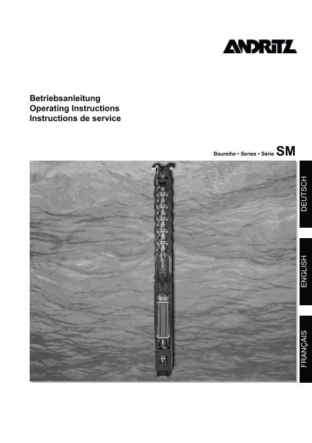
<strong>Betriebsanleitung</strong><br />
<strong>Operating</strong> <strong>Instructions</strong><br />
<strong>Instructions</strong> <strong>de</strong> service<br />
Baureihe • Series • Série SM<br />
FRANÇAIS<br />
ENGLISH<br />
DEUTSCH
Baureihe SM<br />
Inhaltsverzeichnis<br />
Seite<br />
1. Allgemein .................................................................................................................................4<br />
1.1 Einleitung ............................................................................................................................................................................. 4<br />
1.2 Benennung........................................................................................................................................................................... 4<br />
1.3 Fabrikschild .......................................................................................................................................................................... 4<br />
1.4 Sicherheitshinweise ............................................................................................................................................................. 4<br />
2. Unbedingt beachten................................................................................................................4<br />
2.1 Verwendungszweck ............................................................................................................................................................. 4<br />
2.2 Anfor<strong>de</strong>rungen beim Einsatz................................................................................................................................................ 5<br />
2.3 Anfor<strong>de</strong>rungen <strong>de</strong>r EG-Richtlinien ....................................................................................................................................... 6<br />
3. Transport und Lagerung.........................................................................................................6<br />
3.1 Transportieren...................................................................................................................................................................... 6<br />
3.2 Lagerung.............................................................................................................................................................................. 6<br />
3.3 Auspacken ........................................................................................................................................................................... 7<br />
3.4 Erste Überprüfung................................................................................................................................................................ 7<br />
4. Motor montieren ......................................................................................................................7<br />
4.1 Benötigtes Werkzeug ........................................................................................................................................................... 7<br />
4.2 Auffüllen <strong>de</strong>s Motors ............................................................................................................................................................ 7<br />
4.3 Zusammenbau von Motor und Pumpe (Aggregat)............................................................................................................... 7<br />
4.4 Motorkabel anschließen....................................................................................................................................................... 8<br />
5. Elektrischer Anschluss...........................................................................................................8<br />
DEUTSCH<br />
5.1 Voraussetzungen ................................................................................................................................................................. 8<br />
5.2 Energieversorgung............................................................................................................................................................... 8<br />
5.3 Motor anschließen................................................................................................................................................................ 9<br />
6. Inbetriebnahme......................................................................................................................10<br />
6.1 Voraussetzungen ............................................................................................................................................................... 10<br />
6.2 Prüfung vor <strong>de</strong>r Inbetriebnahme ........................................................................................................................................ 10<br />
6.3 Motor einschalten............................................................................................................................................................... 10<br />
6.4 Beim Testbetrieb................................................................................................................................................................ 10<br />
7. Wartung..................................................................................................................................11<br />
8.1 Allgemein ........................................................................................................................................................................... 11<br />
8.2 Elektrische Störungen........................................................................................................................................................ 11<br />
8. Störungen : Ursachen und Beseitigung..............................................................................11<br />
8.1 Allgemein ........................................................................................................................................................................... 11<br />
8.2 Elektrische Störungen........................................................................................................................................................ 11<br />
8.3 Mechanische o<strong>de</strong>r hydraulische Störungen....................................................................................................................... 11<br />
8.4 Störungen im Überblick...................................................................................................................................................... 12<br />
9. Anhang ...................................................................................................................................33<br />
9.1 Richtwerttabellen für Kühlmitteltemperaturen .................................................................................................................... 33<br />
9.2 Anschlussplan PT100 mit Ausgleichsleitung...................................................................................................................... 40<br />
3
Baureihe SM<br />
1. Allgemein<br />
1.1 Einleitung<br />
Wir gratulieren Ihnen zu Ihrer Entscheidung für unsere Unterwassermotoren.<br />
Mit diesem Motor haben Sie ein hochwertiges<br />
Qualitätsprodukt erstan<strong>de</strong>n, in <strong>de</strong>ren Entwicklung viele Jahre<br />
Erfahrung im Bereich <strong>de</strong>r Motorentechnik eingeflossen sind.<br />
Die folgen<strong>de</strong> Anleitung hilft Ihnen bei <strong>de</strong>r Inbetriebnahme und<br />
<strong>de</strong>m Betrieb <strong>de</strong>s Motors. Sollten Sie darüber hinaus weitere<br />
Unterstützung benötigen, wen<strong>de</strong>n Sie sich bitte an unser Werk.<br />
Um eine schnelle und reibungslose Bearbeitung zu ermöglichen,<br />
geben Sie bitte bei Rückfragen immer die Fabrikationsnummer<br />
<strong>de</strong>s Motors an. Sie fin<strong>de</strong>n diese min<strong>de</strong>stens 5-stellige<br />
Zahl auf <strong>de</strong>m Typenschild <strong>de</strong>s Motors bzw. an <strong>de</strong>r Außenseite<br />
<strong>de</strong>r oberen Gehäusekappe (oberes Motorlager).<br />
1.2 Benennung<br />
Baureihe<br />
Min. Brunnendurchmesser [Zoll]<br />
Motorausführung (Optional)<br />
T = Hochwärmebeständige Wicklung<br />
F = 60 Hz Ausführung<br />
R = Bergbau<br />
S = Son<strong>de</strong>rausführung<br />
Motornennleistung P 2 [kW]<br />
Polzahl<br />
1.3 Fabrikschild<br />
Wir empfehlen vor <strong>de</strong>m Einbau <strong>de</strong>s Motors die technischen<br />
Werte auf <strong>de</strong>m Fabrikschild in das nachfolgen<strong>de</strong> Feld zu übertragen.<br />
Damit haben Sie auch nach <strong>de</strong>m Einbau die wichtigsten<br />
Informationen immer schnell zur Hand.<br />
Typ<br />
Nr.<br />
Bj.<br />
1.4 Sicherheitshinweise<br />
Rep.<br />
~ Iso IP<br />
SM 8 T / 75 / 2<br />
Beispiel<br />
P 1 kW P 2 kW<br />
U<br />
V Hz<br />
I<br />
A cos <br />
n<br />
min -1<br />
Abbildung : Fabrikschild<br />
• Die Motoren dürfen nur unter genauer Beachtung dieser<br />
Anleitung verwen<strong>de</strong>t wer<strong>de</strong>n. Bewahren Sie diese Anleitung<br />
auf, damit sie Ihnen auch bei später auftreten<strong>de</strong>n<br />
Fragen zur Verfügung steht.<br />
• Beachten Sie ergänzend zu dieser <strong>Betriebsanleitung</strong> die<br />
separate <strong>Betriebsanleitung</strong> “Sicherheitshinweise”, alle<br />
Hinweise <strong>de</strong>r Vertragsdokumentation, sowie alle evtl.<br />
mitgelieferten Merkblätter und <strong>Betriebsanleitung</strong>en an<strong>de</strong>rer<br />
Komponenten (Pumpenbetriebsanleitung etc.).<br />
• Gefahren von elektrischem Strom müssen ausgeschaltet<br />
wer<strong>de</strong>n (entsprechend <strong>de</strong>n Bestimmungen<br />
<strong>de</strong>r VDE und <strong>de</strong>r Stromversorger).<br />
• Arbeiten am elektrischen System dürfen nur<br />
von qualifizierten Fachkräften durchgeführt<br />
wer<strong>de</strong>n.<br />
• Vor Wartungs- und Reparaturarbeiten muss<br />
<strong>de</strong>r Motor vollständig von <strong>de</strong>r elektrischen<br />
Spannungsversorgung getrennt wer<strong>de</strong>n.<br />
• Motoren o<strong>de</strong>r Aggregate die mit gesundheitsschädlichen<br />
Substanzen in Kontakt gekommen sind, müssen vor jeglichen<br />
Arbeiten <strong>de</strong>kontaminiert wer<strong>de</strong>n.<br />
Bei Einsendung zum Hersteller o<strong>de</strong>r zu einer Vertragswerkstätte<br />
müssen diese vor <strong>de</strong>m Versand <strong>de</strong>kontaminiert<br />
o<strong>de</strong>r <strong>de</strong>utlich sichtbar gekennzeichnet wer<strong>de</strong>n.<br />
• Unmittelbar nach<strong>de</strong>m die Arbeiten been<strong>de</strong>t sind, müssen<br />
alle Sicherheits- und Schutzeinrichtungen wie<strong>de</strong>r eingesetzt<br />
und in Betrieb genommen wer<strong>de</strong>n.<br />
• Die Betriebssicherheit <strong>de</strong>s ausgelieferten Motors ist nur<br />
gewährleistet, wenn <strong>de</strong>r Motor entsprechend <strong>de</strong>n Vorschriften<br />
und Grenzwerten <strong>de</strong>r Vertragsdokumentation<br />
(<strong>Betriebsanleitung</strong> etc.) eingesetzt wird. Die vorgegebenen<br />
Grenzwerte dürfen in keinem Fall überschritten wer<strong>de</strong>n.<br />
2. Unbedingt beachten<br />
2.1 Verwendungszweck<br />
Nachwickelbare, wassergefüllte Unterwassermotoren sind<br />
ausschließlich für <strong>de</strong>n Betrieb unter Wasser geeignet. Sie wer<strong>de</strong>n<br />
vorwiegend für <strong>de</strong>n Antrieb von Pumpen eingesetzt.<br />
Die Motoren wer<strong>de</strong>n standardmäßig in unbefülltem Zustand<br />
ausgeliefert. Um ausreichen<strong>de</strong> Schmierung und<br />
Kühlung <strong>de</strong>s Motors zu gewährleisten, muss unbedingt sichergestellt<br />
wer<strong>de</strong>n, dass <strong>de</strong>r Motor gemäß <strong>de</strong>n Herstellerhinweisen<br />
befüllt und untergetaucht wur<strong>de</strong>, bevor eine<br />
Inbetriebnahme erfolgt!<br />
2.1.1 Typische Einsatzbereiche<br />
Typische Einsatzbereiche für die mit Unterwassermotoren angetriebenen<br />
Pumpen sind:<br />
• Trinkwasserversorgung in Städten und Gemein<strong>de</strong>n.<br />
• Brunnen in Wasserwerken.<br />
• Wasserhaltung im Tief- und Bergbau.<br />
• Druckerhöhungsanlagen in <strong>de</strong>r Industrie<br />
(mit Pumpe im Druckmantel).<br />
2.1.2 Zulässige Medien<br />
Die Unterwassermotoren dürfen ausschließlich in reinen,<br />
dünnflüssigen Medien eingesetzt wer<strong>de</strong>n, wie zum Beispiel<br />
Trink- und Brauchwasser.<br />
4
Baureihe SM<br />
Generell ist die Eignung und Materialauswahl <strong>de</strong>r Motoren Aufgrund<br />
von Wasseranalysen o<strong>de</strong>r chem. Analysen durch <strong>de</strong>n<br />
Besteller zu prüfen. Dies kann wahlweise auch in Zusammenarbeit<br />
mit <strong>de</strong>m Motorhersteller erfolgen. Die Verantwortung für<br />
die richtige Materialauswahl liegt beim Besteller.<br />
2.1.5 Kühlmantel<br />
Kann die gefor<strong>de</strong>rte minimale Geschwindigkeit <strong>de</strong>s Kühlmittels<br />
nicht erreicht wer<strong>de</strong>n, z.B. wenn die Einlassöffnung <strong>de</strong>s Brunnens<br />
oberhalb <strong>de</strong>s Motors liegt o<strong>de</strong>r es sich um einen Brunnen<br />
mit großem Durchmesser han<strong>de</strong>lt, ist ein Kühlmantel erfor<strong>de</strong>rlich.<br />
Dieser sollte <strong>de</strong>n Motor komplett und die Wassereintrittsöffnung<br />
<strong>de</strong>r Pumpe <strong>de</strong>rart umschließen, dass eine<br />
Zwangskühlung <strong>de</strong>s Motors erfolgt (siehe Bild 1).<br />
Die Motoren dürfen ausschließlich in Medien eingesetzt<br />
wer<strong>de</strong>n, die in <strong>de</strong>r Vertragsdokumentation ausdrücklich<br />
zugelassen sind!<br />
2.1.3 Nicht zulässige Medien<br />
Auf keinen Fall dürfen die Unterwassermotoren in an<strong>de</strong>ren Medien<br />
eingesetzt wer<strong>de</strong>n,<br />
• insbeson<strong>de</strong>re nicht zur För<strong>de</strong>rung von Luft, explosiven Medien<br />
o<strong>de</strong>r Schmutzwasser.<br />
• Für <strong>de</strong>n Einsatz in aggressiven Medien stehen Motoren aus<br />
korrosionsbeständigen Materialien zur Verfügung.<br />
Die Verantwortung für die richtige Materialauswahl liegt beim<br />
Besteller.<br />
2.1.4 Kühlmitteltemperatur und Geschwindigkeit<br />
Im Betrieb wird die Motorbetriebswärme über <strong>de</strong>n Motormantel<br />
und eventuell angebaute Wärmetauscher an das umfließen<strong>de</strong><br />
Medium abgegeben.<br />
Abhängig von Fließgeschwindigkeit und <strong>de</strong>n zu erwarten<strong>de</strong>n<br />
Ablagerungen am Motormantel, darf die für diese Einsatzbedingung<br />
festgelegte maximale Kühlmitteltemperatur nicht<br />
überschritten wer<strong>de</strong>n, um eine optimale Kühlung zu gewährleisten.<br />
Angaben zu diesen Werten fin<strong>de</strong>n Sie in <strong>de</strong>r Regel in <strong>de</strong>r beiliegen<strong>de</strong>n<br />
Vertragsdokumentation.<br />
Für Standardmotoren fin<strong>de</strong>n Sie im Anhang dieser Anleitung<br />
Richtwerttabellen für die maximal zulässigen Kühlmitteltemperaturen<br />
in Abhängigkeit verschie<strong>de</strong>ner Einsatzbedingungen.<br />
Empfohlen wird eine Kühlmittelgeschwindigkeit von min<strong>de</strong>stens<br />
> 0,5 m/s entlang <strong>de</strong>m Motor.<br />
Sollten die erfor<strong>de</strong>rlichen Informationen nicht gefun<strong>de</strong>n wer<strong>de</strong>n,<br />
o<strong>de</strong>r Unklarheiten bestehen, so wen<strong>de</strong>n Sie sich bitte an<br />
<strong>de</strong>n Motorhersteller.<br />
Der Einsatz bei höheren Mediumtemperaturen o<strong>de</strong>r niedrigeren<br />
Fließgeschwindigkeiten ist nur nach Rückfrage mit<br />
<strong>de</strong>m Hersteller o<strong>de</strong>r bei ausdrücklichem Vermerk in <strong>de</strong>r<br />
Vertragsdokumentation zulässig. An<strong>de</strong>rnfalls kann dies<br />
zur Überhitzung und Beschädigung <strong>de</strong>s Motors führen.<br />
Bild 1: Kühlmantel<br />
Die Kühlmittelgeschwindigkeit ergibt sich aus <strong>de</strong>m Brunnendurchmesser<br />
und <strong>de</strong>r För<strong>de</strong>rmenge <strong>de</strong>r Pumpe.<br />
Berechnung <strong>de</strong>r Fließgeschwindigkeit:<br />
V = Fließgeschwindigkeit<br />
Q = För<strong>de</strong>rmenge [m³/h]<br />
D = Brunnendurchmesser [mm]<br />
d = Motordurchmesser [mm]<br />
2.2 Anfor<strong>de</strong>rungen beim Einsatz<br />
• Die maximale Eintauchtiefe unterhalb <strong>de</strong>s Wasserspiegels<br />
darf 350 m nicht überschreiten.<br />
• Größere Eintauchtiefen auf Anfrage.<br />
• Die maximal zulässige Schalthäufigkeit <strong>de</strong>s Motors darf<br />
nicht überschritten wer<strong>de</strong>n. Vor <strong>de</strong>m erneuten Einschalten ist<br />
eine festgelegte Schaltpause einzuhalten . Ansonsten erfolgt<br />
eine Überhitzung und Beschädigung <strong>de</strong>r Wicklung!<br />
Die folgen<strong>de</strong> Tabelle zeigt die gelten<strong>de</strong>n Werte für Schalthäufigkeiten<br />
und Schaltpausen:<br />
Typ<br />
V Qx 353,<br />
68<br />
= 2 2<br />
D - d<br />
[ m/<br />
s]<br />
Schalthäufigkeit<br />
[Schaltungen<br />
pro h]<br />
Stillstandszeit<br />
[min]<br />
SM8 15 2<br />
SM8T, SM8F,<br />
SM8FT<br />
10 2<br />
SM9, SM9T,<br />
SM9F, SM9FT<br />
8 3<br />
SM10, SM10T,<br />
SM10F, SM10FT<br />
8 3<br />
SM12, SM12T,<br />
SM12F, SM12FT<br />
8 3<br />
SM14, SM14T,<br />
SM14F, SM14FT<br />
4 5<br />
Tabelle 1: Schalthäufigkeiten und Stillstandszeiten<br />
• Die Abführung <strong>de</strong>r Motorbetriebswärme an das För<strong>de</strong>rmedium<br />
erfolgt über die Motoroberfläche. Der Einsatz in Medien,<br />
bei <strong>de</strong>nen die Gefahr von Ablagerungen besteht, ist nur zulässig,<br />
wenn dies in <strong>de</strong>r Vertragsdokumentation berücksichtigt<br />
ist.<br />
DEUTSCH<br />
5
Baureihe SM<br />
• Auf <strong>de</strong>m Motor dürfen keine zusätzlichen Anstriche aufgebracht<br />
wer<strong>de</strong>n, da diese die Wärmeabführung <strong>de</strong>s Motors beeinträchtigen.<br />
• Der Motor ist in <strong>de</strong>r Regel nach <strong>de</strong>n Vorgaben <strong>de</strong>r Bestellung<br />
für die direkte (DOL) o<strong>de</strong>r Stern-Dreieck Einschaltung geeignet.<br />
Einschaltung per Sanftanlaufgerät bzw. Betrieb über<br />
Frequenzumformer sind nur zulässig, wenn dies ausdrücklich<br />
in <strong>de</strong>r Vertragsdokumentation zugelassen ist. Die Benutzung<br />
eines Sanftanlaufgerätes o<strong>de</strong>r eines Frequenzumformers<br />
erfor<strong>de</strong>rt eine spezielle Motorauslegung bzw. Anfor<strong>de</strong>rungen<br />
an die Geräte (Sanftanlaufgerät, Frequenzumformer<br />
etc.) und <strong>de</strong>ren Einstellungen.<br />
• Die Motoren sind für <strong>de</strong>n vertikalen Einbau (Wellenen<strong>de</strong><br />
nach oben angeordnet) geeignet. Ein horizontaler Einbau<br />
darf nur erfolgen, wenn dies ausdrücklich in <strong>de</strong>r Vertragsdokumentation<br />
zugelassen ist.<br />
• Planen Sie unbedingt ein Rückschlagventil im Steigrohr<br />
ein, falls nicht bereits in <strong>de</strong>r Pumpe ein solches eingebaut ist.<br />
Wir empfehlen <strong>de</strong>n Einsatz eines fe<strong>de</strong>rbelasteten Rückschlagventils.<br />
• Bei Brunnen mit variablem Wasserzufluss empfiehlt sich <strong>de</strong>r<br />
Einbau eines Niveauwächters, um einen Trockenlauf von<br />
Motor und Pumpe zu verhin<strong>de</strong>rn.<br />
<strong>de</strong>s Frequenzumrichters sicherstellen, dass die beson<strong>de</strong>ren<br />
Gegebenheiten bei Unterwassermotoren berücksichtigt wer<strong>de</strong>n.<br />
• Energie- und Steuerleitung zwischen Motor und Brunnenkopf<br />
müssen getrennt voneinan<strong>de</strong>r verlegt und dort über einen Anschlusskasten<br />
verklemmt wer<strong>de</strong>n. Dabei sind Steuerleitungen<br />
in abgeschirmter Ausführung einzusetzen.<br />
• Weiterführen<strong>de</strong> Leitungen zwischen Anschlusskasten und<br />
Schaltanlage sind bauseits mit abgeschirmten Anschlusseitungen<br />
auszuführen.<br />
2.3 Anfor<strong>de</strong>rungen <strong>de</strong>r EG-Richtlinien<br />
Bei <strong>de</strong>n Unterwassermotoren han<strong>de</strong>lt es sich um eine Komponente<br />
gemäß <strong>de</strong>r EG-Richtline „Maschinen“. Sie dürfen <strong>de</strong>n<br />
Motor daher erst dann in Betrieb nehmen, wenn Sie<br />
• eine vollständige Maschine hergestellt haben, z.B. durch<br />
die Verbindung mit <strong>de</strong>r anzutreiben<strong>de</strong>n Pumpe,<br />
• die in <strong>de</strong>n anwendbaren EG-Richtlinien gefor<strong>de</strong>rten Schutzanfor<strong>de</strong>rungen<br />
erfüllt haben,<br />
• die Einhaltung <strong>de</strong>r Schutzanfor<strong>de</strong>rungen durch die EG-Konformitätserklärung<br />
bescheinigt<br />
• und nach außen hin durch Anbringen <strong>de</strong>s CE-Zeichens<br />
kenntlich gemacht haben!<br />
3. Transport und Lagerung<br />
Trockenlauf führt umgehend zu Defekten an Motor und<br />
Pumpe.<br />
2.2.1 Spezielle Anfor<strong>de</strong>rungen -<br />
Einschaltung mit Sanftanlaufgerät<br />
• Startspannung: U A ≥ 70 % <strong>de</strong>r Bemessungsspannung<br />
• Hochlauf-Zeit/Rampe: Voreinstellung auf t H ≤ 5 s<br />
(die tatsächliche Zeit bis zum Erreichen <strong>de</strong>r Bemessungsdrehzahl<br />
ist dann 2 - 3 s).<br />
• Auslaufzeit/Rampe: Voreinstellung t A ≤ 5 s.Wenn möglich,<br />
dann sollte auf die Auslauf-Rampe ganz verzichtet wer<strong>de</strong>n.<br />
• Das Sanftanlaufgerät muss nach <strong>de</strong>m Hochlauf durch ein<br />
Schütz überbrückt wer<strong>de</strong>n, um Leistungsverluste im Sanftanlaufgerät<br />
und im Motor zu vermei<strong>de</strong>n. Insbeson<strong>de</strong>re hierzu<br />
bitte Rückfrage beim Lieferanten <strong>de</strong>s Sanftanlaufgeräts.<br />
2.2.2 Spezielle Anfor<strong>de</strong>rungen -<br />
Betrieb mit Frequenz-Umrichter<br />
• Bedingt durch höhere elektrische Verluste im Motor, muss bei<br />
<strong>de</strong>r Motorauslegung eine Leistungsreserve von min<strong>de</strong>stens<br />
10 % eingeplant wer<strong>de</strong>n.<br />
• Min<strong>de</strong>st-Betriebsfrequenz: f min = 30 Hz<br />
Auf ausreichen<strong>de</strong> Kühlmittelgeschwindigkeit entlang <strong>de</strong>m<br />
Motor ist zu achten.<br />
• Maximale Betriebsfrequenz: f max = Nennfrequenz Motor<br />
Die Nennfrequenz <strong>de</strong>s Motors beträgt je nach Motorausführung<br />
50 bzw. 60 Hz! Diese können Sie <strong>de</strong>m Typenschild o<strong>de</strong>r<br />
<strong>de</strong>r Vertragsdokumentation entnehmen. Nennfrequenz und<br />
Nennleistung <strong>de</strong>s Motors darf nicht überschritten wer<strong>de</strong>n.<br />
• Hochlauf-Zeit (f = 0 bis f min ): t H = 3 s.<br />
• Auslauf-Zeit (f = f min bis 0 ): t A = 3 s.<br />
• Der Motorbemessungsstrom darf nicht überschritten wer<strong>de</strong>n.<br />
• Maximal zulassiger Spannungsanstieg ≤ 500 V/µs.<br />
Maximal zulässige Spannungsspitze gegen Er<strong>de</strong> bei PVC-<br />
Isolation ≤ 800 V und bei PE2/PA-Isolation ≤ 1000 V.<br />
Hinweis: Diese Grenzwerte wer<strong>de</strong>n in <strong>de</strong>r Regel mit Hilfe eines<br />
Sinusfilters bzw. du / dt -Filters erreicht.<br />
• Das Steuer- und Regelverfahren <strong>de</strong>s Frequenzumrichters<br />
muss einer linearen U / f -Kennliniensteuerung entsprechen.<br />
Bei an<strong>de</strong>ren Steuer- und Regelprinzipien muss <strong>de</strong>r Hersteller<br />
3.1 Transportieren<br />
Verletzungsgefahr<br />
• Gewicht und Schwerpunkt beachten.<br />
• Benutzen Sie nur geeignetes Transportmittel und<br />
Hebezeug mit ausreichen<strong>de</strong>r Tragkraft.<br />
• Motor beim Transport nicht kippen.<br />
• Treten Sie nicht unter schweben<strong>de</strong> Lasten.<br />
• Zugbelastungen an Anschluss- und Steuerkabeln<br />
vermei<strong>de</strong>n.<br />
• Bei Einsatz von Ketten und Stahlseilen besteht die<br />
Gefahr <strong>de</strong>s Verrutschens.<br />
Motor beim Handling und Transport nicht gegen feste Hin<strong>de</strong>rnisse<br />
schlagen lassen!<br />
3.2 Lagerung<br />
Unterwassermotoren stellen spezielle Anfor<strong>de</strong>rungen an die<br />
Lagerung, da bestimmte Motorbauteile Aufgrund technischer<br />
Randbedingungen nicht aus korrosionsbeständigen Werkstoffen<br />
gerfertigt wer<strong>de</strong>n können. Die Nichteinhaltung dieser Anfor<strong>de</strong>rungen<br />
führt zu Schä<strong>de</strong>n am Motor. Von <strong>de</strong>r richtigen<br />
Lagerung <strong>de</strong>s Motors ist die spätere einwandfreie Funktion abhängig.<br />
• Die Lieferung <strong>de</strong>r Motoren erfolgt standardmäßig ohne<br />
Motorfüllung. Ist dies <strong>de</strong>r Fall, muss <strong>de</strong>r Motor sofort<br />
nach Erhalt mit sauberem Trinkwasser (kein <strong>de</strong>stilliertes<br />
Wasser) aufgefüllt wer<strong>de</strong>n!<br />
• Lagerraum : Staubfrei, trocken, gegen Hitze und Frost<br />
gesichert.<br />
• Lagern Sie <strong>de</strong>n Motor nicht im Bereich direkter Sonneneinstrahlung<br />
o<strong>de</strong>r an<strong>de</strong>rer Wärmequellen. Auf keinen Fall darf<br />
<strong>de</strong>r Motor auf über 60 °C erhitzt wer<strong>de</strong>n. An<strong>de</strong>rnfalls kann<br />
die Motorflüssigkeit durch Aus<strong>de</strong>hnung entweichen. Der Motor<br />
wür<strong>de</strong> hierdurch späteren Scha<strong>de</strong>n nehmen.<br />
• Bei Lagerung <strong>de</strong>s Motors bei Temperaturen unter <strong>de</strong>m Gefrierpunkt<br />
ist ein Frostschutz notwendig. Kontaktieren Sie<br />
hierzu <strong>de</strong>n Hersteller. Der Einsatz falscher, nicht zulässiger<br />
Frostschutzmittel kann <strong>de</strong>n Motor erheblich beschädigen.<br />
6
Baureihe SM<br />
• Motor stehend (Wellenen<strong>de</strong> nach oben) lagern!<br />
Sorgen Sie bei stehen<strong>de</strong>r Lagerung dafür, dass <strong>de</strong>r Motor<br />
nicht umfallen kann.<br />
• Monatlich Motorwelle drehen. Lage <strong>de</strong>r Welle zum vorhergehen<strong>de</strong>n<br />
Zustand verän<strong>de</strong>rn.<br />
3.3 Auspacken<br />
Lieferung auf Vollständigkeit und Unversehrtheit überprüfen.<br />
Lassen Sie festgestellte Mängel vom Transportunternehmen<br />
auf <strong>de</strong>m Orginal-Frachtbrief bestätigen und unterrichten Sie<br />
uns unverzüglich darüber.<br />
Verletzungsgefahr<br />
• Nehmen Sie <strong>de</strong>n Motor vorsichtig aus <strong>de</strong>r Verpakkung,<br />
um Schä<strong>de</strong>n zu vermei<strong>de</strong>n.<br />
• Gewicht und Schwerpunkt beachten.<br />
• Benutzen Sie nur geeignetes Hebezeug mit ausreichen<strong>de</strong>r<br />
Tragkraft.<br />
• Treten Sie nicht unter schweben<strong>de</strong> Lasten.<br />
• Schützen Sie die Motorkabel vor mechanischer<br />
Einwirkung.<br />
3.4 Erste Überprüfung<br />
Prüfen Sie nach <strong>de</strong>m Auspacken, ob äußerlich Beschädigungen<br />
sichtbar sind, zum Beispiel<br />
• am Gehäusebo<strong>de</strong>n<br />
• am Gehäuse (Stator)<br />
• an <strong>de</strong>r oberen und unteren Gehäusekappe (Motorlager)<br />
• am Anschluss- o<strong>de</strong>r Steuerkabel<br />
Wenn Sie Schä<strong>de</strong>n feststellen, dürfen Sie <strong>de</strong>n Motor<br />
nicht montieren o<strong>de</strong>r in Betrieb nehmen. Bei beschädigtem<br />
Motor besteht Verletzungs- und<br />
Lebensgefahr.<br />
4. Motor montieren<br />
4.2.1 Motorflüssigkeit einfüllen<br />
Verletzungsgefahr!<br />
Sorgen Sie dafür, dass <strong>de</strong>r Motor während <strong>de</strong>s Vorgangs<br />
nicht umfallen kann.<br />
• Motor in senkrechte Lage bringen.<br />
• Der Motor ist grundsätzlich in senkrechter Lage aufzufüllen!<br />
• Verschlussschraube <strong>de</strong>r Auffüll- und Entlüftungsöffnung<br />
entfernen.<br />
• Trichter (Winkeltrichter) in die Auffüllöffnung einsetzen.<br />
• Motor über Trichter mit Wasser drucklos befüllen, bis das<br />
Wasser aus <strong>de</strong>r Füllöffnung tritt.<br />
• Füllstand nach 2 Stun<strong>de</strong>n Wartezeit erneut kontrollieren. Der<br />
Füllvorgang ist solange durchzuführen, bis das Wasser in <strong>de</strong>r<br />
Auffüll- und Entlüftungsöffnung blasenfrei stehen bleibt.<br />
• Verschlussschraube mit Dichtung sind wie<strong>de</strong>r dicht<br />
einzudrehen.<br />
4.3 Zusammenbau von Motor und Pumpe (Aggregat)<br />
Verwen<strong>de</strong>n Sie <strong>de</strong>n Motor niemals mit beschädigten<br />
Pumpen o<strong>de</strong>r Teilen. Wegen <strong>de</strong>r hohen<br />
Antriebskräfte kann es an<strong>de</strong>renfalls zu Unfällen<br />
kommen. Es besteht Verletzungs- und Lebensgefahr!<br />
4.3.1 Vorbereiten<strong>de</strong> Prüfungen<br />
• Entfernen Sie ggf. <strong>de</strong>n Wellenschutz.<br />
• Drehen Sie die Motorwelle vor <strong>de</strong>m Zusammenbau mit <strong>de</strong>r<br />
Hand o<strong>de</strong>r mit einem Hilfswerkzeug durch. Es darf nur geeignetes<br />
Hilfswerkzeug eingesetzt wer<strong>de</strong>n um mechanische Beschädiungen<br />
an <strong>de</strong>r Welle zu verhin<strong>de</strong>rn. Die Welle muss<br />
nach Überwindung <strong>de</strong>r Haftreibung frei laufen. Falls nicht,<br />
muss die Ursache ermittelt wer<strong>de</strong>n.<br />
• Achten Sie darauf, dass die Oberflächen <strong>de</strong>r zu verbin<strong>de</strong>n<strong>de</strong>n<br />
Teile schmutz- und staubfrei sind.<br />
DEUTSCH<br />
4.1 Benötigtes Werkzeug<br />
Für die erfor<strong>de</strong>rlichen Überprüfungen und eine einwandfreie<br />
Montage benötigen Sie folgen<strong>de</strong> Werkzeuge und Instrumente:<br />
• Isolationsmessgerät mit 500 Volt Prüfspannung bzw. 5000<br />
Volt Prüfspannung für Hochspannungsmotoren mit mehr als<br />
3000 Volt Betriebsspannung. Anzeige bis min<strong>de</strong>stens 200<br />
MOhm.<br />
• Geeignetes Werkzeug für die Befüllung und <strong>de</strong>n Zusammenbau<br />
<strong>de</strong>s Motors (Wasserbehälter, Trichter, Schraubenschlüssel,<br />
Drehmomentschlüssel etc.).<br />
4.2 Auffüllen <strong>de</strong>s Motors<br />
• Vor <strong>de</strong>r Installation muss <strong>de</strong>r Motor mit sauberem Trinkwasser<br />
(kein <strong>de</strong>stilliertes Wasser) aufgefüllt wer<strong>de</strong>n.<br />
• Wur<strong>de</strong> <strong>de</strong>r Motor mit Motorfüllung geliefert o<strong>de</strong>r bereits<br />
zur Lagerung gefüllt, muss die Motorfüllung vor <strong>de</strong>r Installation<br />
kontrolliert wer<strong>de</strong>n. Wenn die Prüfung ergeben<br />
hat, dass Motorflüssigkeit fehlt, können Sie sauberes<br />
Trinkwasser (kein <strong>de</strong>stilliertes Wasser) nachfüllen.<br />
• Verwen<strong>de</strong>n Sie bitte Füllwasser mit einem PH-Wert zwischen<br />
7 und 7,5, sowie 7...8 <strong>de</strong>utschem Härtegrad, 10-20mg/l Nitrat.<br />
Schwebstoffe und Sand dürfen nicht enthalten sein. Passen<strong>de</strong><br />
Messgeräte sind auf Anfrage erhältlich.<br />
• Für die Lagerung konservierte bzw. mit Frostschutz gefüllte<br />
Motoren müssen vor <strong>de</strong>m Einsatz in Trinkwasser entleert, gespült,<br />
gereinigt und anschließend wie<strong>de</strong>r mit sauberem Trinkwasser<br />
gefüllt wer<strong>de</strong>n.<br />
4.3.2 Zusammenbau<br />
4.3.2.1 Motoren mit NEMA-Kupplung (SM8, SM9)<br />
• Bestreichen Sie das Innenteil <strong>de</strong>r Kupplung mit einem wasserfesten,<br />
säurefreien Fett (z.B. Mobil FM 102, Texaco Cygnus<br />
2661, Gleitmo 746). Das Fett minimiert die Reibung und<br />
bietet einen zusätzlichen Schutz gegen das Eindringen von<br />
Sand.<br />
• Achten Sie beim Zusammenfügen von Motor und Pumpe darauf,<br />
dass die Verzahnung durch einen O-Ring umfasst wird.<br />
Dieser O-Ring verhin<strong>de</strong>rt ein Eindringen von Sand und<br />
Schmutz in die Wellenverzahnung.<br />
• Richten Sie die Pumpen- und Motorwelle gegeneinan<strong>de</strong>r aus,<br />
und führen Sie Pumpe und Motor zusammen.<br />
• Die Pumpen- und Motorwellen dürfen keine starre Verbindung<br />
(Kupplung) in Axialrichtung haben.<br />
• Die Kupplung soll auf <strong>de</strong>r Pumpenwelle befestigt sein und auf<br />
<strong>de</strong>r Motorwelle gleiten.<br />
• Benutzen Sie nur Befestigungschrauben <strong>de</strong>r entsprechen<strong>de</strong>n<br />
Güteklasse und Abmessungen, die vom Pumpenhersteller<br />
vorgeschrieben und zugelassen sind.<br />
• Halten Sie die vom Pumpenhersteller vorgeschriebenen Anzugsdrehmomente<br />
ein.<br />
• Verschrauben Sie <strong>de</strong>n Motor mit <strong>de</strong>m Aggregat und ziehen<br />
Sie die Befestigungsschrauben vorschriftsmäßig über Kreuz<br />
an.<br />
7
Baureihe SM<br />
4.3.2.2 Motoren mit Wellenkupplung<br />
(SM10, SM12, SM14)<br />
Die Montage von Motor und Pumpe erfor<strong>de</strong>rt spezielle Kenntnisse<br />
über die Einstellung <strong>de</strong>r Pumpe und sollte entsprechend<br />
<strong>de</strong>n Anfor<strong>de</strong>rungen <strong>de</strong>r Pumpe vorgenommen wer<strong>de</strong>n.<br />
Bei <strong>de</strong>r Montage ist auf ausreichen<strong>de</strong> Dimensionierung <strong>de</strong>r<br />
Verbindungselemente und Freigängigkeit <strong>de</strong>s Rotors zu achten.<br />
4.3.3 Abschließen<strong>de</strong> Prüfungen<br />
Sollte die Kupplungsstelle beim Betrieb frei zugänglich sein,<br />
müssen Sie diese unbedingt gegen Berührung schützen!<br />
4.4 Motorkabel anschließen<br />
• Das Kabel darf auf keinen Fall scharfe Kanten berühren<br />
können.<br />
• Verlegen Sie das Kabel entlang <strong>de</strong>r Pumpe und schützen Sie<br />
es vor Beschädigungen mit <strong>de</strong>r Kabelschutzschiene. Beachten<br />
Sie hierzu auch die Angaben <strong>de</strong>s Pumpenherstellers.<br />
4.4.1 Anschluss <strong>de</strong>s Erdleiters<br />
• Prüfen Sie ob die Motoren mit Erdleiter ausgeliefert wur<strong>de</strong>n.<br />
Dies hängt von <strong>de</strong>r bestellten Anschlussvariante <strong>de</strong>s Motors<br />
ab.<br />
• Bauseits ist für <strong>de</strong>n fachgerechten Anschluss eines Erdleiters<br />
zu sorgen. Besitzt <strong>de</strong>r Motor keinen Erdleiter so ist an <strong>de</strong>r<br />
oberen Gehäusekappe <strong>de</strong>s Motors eine entsprechen<strong>de</strong> Erdungsklemme<br />
vorhan<strong>de</strong>n, an <strong>de</strong>r ein seperater Erdleiter fachgerecht<br />
angeschlossen wer<strong>de</strong>n muss.<br />
4.4.2 Motorkabel verlängern<br />
Das mitgelieferte Motorkabel kann bauseits verlängert wer<strong>de</strong>n.<br />
Verwen<strong>de</strong>n Sie hierzu nur Verlängerungskabel<br />
- <strong>de</strong>ren Material für <strong>de</strong>n Einsatz geeignet sind.<br />
- die für in Ihrem Medium auftreten<strong>de</strong>n Temperaturen zugelassen<br />
sind.<br />
- die einen für die Bedingungen (Leistung, Kabellänge, etc.)<br />
ausreichen<strong>de</strong>n Querschnitt aufweisen.<br />
• Achten Sie bei <strong>de</strong>r Auswahl <strong>de</strong>s Kabels sowohl auf eine entsprechen<strong>de</strong><br />
Spannungsfestigkeit, als auch auf die Eignung<br />
für das Medium (insbeson<strong>de</strong>re bei Trinkwasser). Prüfen Sie<br />
bei <strong>de</strong>r Auswahl <strong>de</strong>n Spannungsabfall auf <strong>de</strong>m Kabel um die<br />
Vorgaben <strong>de</strong>r Toleranzen <strong>de</strong>r Versorgungsspannung am Motor<br />
einzuhalten! Nichtbeachtung kann eine Beschädigung <strong>de</strong>s<br />
Motors durch Überhitzung hervorrufen.<br />
• Für die richtige Auswahl und Dimensionierung <strong>de</strong>s Kabels ist<br />
<strong>de</strong>r Installateur verantwortlich!<br />
• Schützen Sie die Verbindungsstelle <strong>de</strong>r Kabel gegen das Eindringen<br />
von Wasser. Hierfür sind am Markt Schrumpfschläuche,<br />
Vergussmassen o<strong>de</strong>r fertige Kabelgarnituren<br />
erhältlich.<br />
• Beachten Sie die Anleitung <strong>de</strong>s jeweiligen Lieferanten über<br />
<strong>de</strong>n Umgang mit <strong>de</strong>m Isoliermaterial.<br />
• Das Kabel ist an je<strong>de</strong>r Steigrohrleitung mit Kabelbän<strong>de</strong>rn<br />
o<strong>de</strong>r Kabelschellen sorgfältig zu befestigen. Je nach Größe<br />
und Schwere <strong>de</strong>s Kabels muss die Befestigung min<strong>de</strong>stens in<br />
3 m Abstand o<strong>de</strong>r kürzer erfolgen. Das Kabel darf keiner<br />
Zugbelastung ausgesetzt wer<strong>de</strong>n.<br />
• Beachten Sie in diesem Zusammenhang auch die Hinweise<br />
<strong>de</strong>s Pumpenherstellers.<br />
• Das Kabel ist beim Einbau (und auch beim Ziehen<br />
<strong>de</strong>s Aggregates) sorgfältig aufgerollt o<strong>de</strong>r ausgelegt<br />
zu lagern, damit bei einem evtl. Absturz <strong>de</strong>r<br />
Pumpe in <strong>de</strong>n Brunnenschacht keine Personeno<strong>de</strong>r<br />
Sachschä<strong>de</strong>n, durch das zwangsläufig mitgerissene<br />
Kabel, auftreten können.<br />
• Es ist darauf zu achten, dass keine Personen in<br />
die aufgerollte Kabelspirale treten.<br />
4.4.3 Isolationswi<strong>de</strong>rstand messen<br />
Führen Sie diese Messung durch, bevor und während das fertig<br />
montierte Aggregat am Einsatzort abgesenkt wird.<br />
• Verbin<strong>de</strong>n Sie das eine Messkabel mit <strong>de</strong>m Erdleiter während<br />
<strong>de</strong>m Absenken.<br />
• Das an<strong>de</strong>re Messkabel verbin<strong>de</strong>n Sie nun nacheinan<strong>de</strong>r mit<br />
je<strong>de</strong>r A<strong>de</strong>r <strong>de</strong>s angeschlossenen Motorkabels - jedoch nicht<br />
mit <strong>de</strong>m Erdleiter.<br />
• Achten Sie darauf, dass die Kontaktstellen sauber sind.<br />
• Der Motor ist in Ordnung, wenn <strong>de</strong>r Isolationswi<strong>de</strong>rstand <strong>de</strong>n<br />
Wert in <strong>de</strong>r nachfolgen<strong>de</strong>n Tabelle nicht unterscheitet. Für<br />
eine korrekte Messung muss <strong>de</strong>r Motor vollständig sein.<br />
Motorzustand<br />
Neuer Motor<br />
Installierter / Reparierter Motor<br />
5. Elektrischer Anschluss<br />
5.1 Voraussetzungen<br />
Dieses Kapitel setzt voraus, dass<br />
• <strong>de</strong>r Motor ordnungsgemäß mit <strong>de</strong>r Pumpe zusammengebaut<br />
ist, wie im Kapitel 4 beschrieben.<br />
• <strong>de</strong>r Isolationswi<strong>de</strong>rstand gemessen und für einwandfrei befun<strong>de</strong>n<br />
wur<strong>de</strong>, wie im Kapitel 4 beschrieben.<br />
• das fertigmontierte Aggregat ordnungsgemäß am Einsatzort<br />
installiert ist, wie in <strong>de</strong>r Anleitung <strong>de</strong>s Pumpenherstellers beschrieben.<br />
Zu Ihrer Sicherheit!<br />
• Arbeiten am elektrischen System dürfen nur von<br />
qualifizierten Fachkäften durchgeführt wer<strong>de</strong>n.<br />
• Bevor Sie irgendwelche Anschlussarbeiten ausführen,<br />
stellen Sie unbedingt erst sicher, dass<br />
auf <strong>de</strong>r gesamten Anlage keinerlei elektrische<br />
Spannung anliegt und niemand versehentlich die<br />
Spannung wie<strong>de</strong>r einschalten kann, während an<br />
<strong>de</strong>r Anlage noch gearbeitet wird.<br />
• Arbeiten Sie niemals an elektrischen Anlagen,<br />
während ein Gewitter aufzieht o<strong>de</strong>r stattfin<strong>de</strong>t.<br />
Durch Blitzschlag können gefährliche Überspannungen<br />
auftreten.<br />
• Wenn Sie diese Hinweise nicht beachten, besteht<br />
akute Lebensgefahr durch einen elektrischen<br />
Schlag.<br />
5.2 Energieversorgung<br />
Spannung<br />
> 1000 Volt<br />
500 MOhm<br />
200 MOhm<br />
Tabelle 2: Isolationswi<strong>de</strong>rstän<strong>de</strong><br />
Die Energieversorgung muss min<strong>de</strong>stens <strong>de</strong>n folgen<strong>de</strong>n Anfor<strong>de</strong>rungen<br />
entsprechen, um Schä<strong>de</strong>n am Motor und unerwünschte<br />
Netzrückwirkungen zu vermei<strong>de</strong>n.<br />
8
Baureihe SM<br />
5.2.1 Energieversorgung durch Netzanschluss<br />
Folgen<strong>de</strong> Toleranzen dürfen nicht überschritten wer<strong>de</strong>n, da<br />
sonst <strong>de</strong>r Motor beschädigt wer<strong>de</strong>n kann:<br />
• Die Spannungstoleranz muss insgesamt in einem Bereich<br />
von -10% bis +6% von <strong>de</strong>r Nennspannung liegen (an <strong>de</strong>n Motorklemmen<br />
gemessen).<br />
• Die Abweichung eines Motorstromes vom Mittelwert aller drei<br />
Ströme darf max. 10% nicht überschreiten.<br />
• Im Betrieb darf <strong>de</strong>r Mittelwert aller 3 Phasenströme <strong>de</strong>n<br />
Nennstrom <strong>de</strong>s Motors nicht überschreiten.<br />
5.3.2 Erdung<br />
4<br />
M<br />
3~<br />
PE<br />
5.3 Motor anschließen<br />
• Beachten Sie hierzu auch die Angaben auf <strong>de</strong>m Typenschild<br />
am Motor und dimensionieren Sie danach die elektrische Anlage.<br />
• Die folgen<strong>de</strong>n Anschlussbeispiele beziehen sich ausschließlich<br />
auf <strong>de</strong>n Motor selber - sie sind keine Empfehlung hinsichtlich<br />
<strong>de</strong>r vorgeschalteten Steuerelemente!<br />
• Für eine fachlich einwandfreie Planung und Ausführung <strong>de</strong>r<br />
Installation ist <strong>de</strong>r Installateur verantwortlich.<br />
5.3.1 Absicherung und Motorschutz<br />
• Planen Sie einen externen Netzschalter (1) ein, um die Anlage<br />
je<strong>de</strong>rzeit spannungsfrei schalten zu können - zum Beispiel<br />
bei Gefahr o<strong>de</strong>r bei Arbeiten an <strong>de</strong>r Anlage.<br />
• Planen Sie bauseits Sicherungen (2) für je<strong>de</strong> einzelne<br />
Phase ein.<br />
• Planen Sie einen Motorschutzschalter (3) ein, wie in <strong>de</strong>r Anschlussbeschreibung<br />
erläutert.<br />
• Planen Sie auch eine Not-Aus-Abschaltung ein, soweit dies<br />
für Ihren Verwendungszweck vorgeschrieben o<strong>de</strong>r erfor<strong>de</strong>rlich<br />
ist!<br />
Bild 3: Erdung<br />
• Der Motor muss geer<strong>de</strong>t wer<strong>de</strong>n. Berücksichtigen Sie bei<br />
<strong>de</strong>r Dimensionierung <strong>de</strong>r Erdverbindung (4) insbeson<strong>de</strong>re<br />
die Motorleistung.<br />
• Fachliche Regeln hierzu fin<strong>de</strong>n Sie in EN 60034-1 und<br />
IEC 364-5-54.<br />
5.3.3 Überspannungsschutz<br />
L1<br />
L2<br />
L3<br />
5<br />
DEUTSCH<br />
L1<br />
L2<br />
L3<br />
PE<br />
1<br />
2<br />
3<br />
U = schwarz<br />
V = braun<br />
W = blau<br />
I> I> I><br />
U V W<br />
M<br />
3~<br />
PE<br />
4<br />
Bild 2: Absicherung und Motorschutz<br />
Bild 4: Überspannungsschutz<br />
• Berücksichtigen Sie in <strong>de</strong>r Spannungszuführung einen entsprechen<strong>de</strong>n<br />
Überspannungsschutz (Blitzschutz) (5).<br />
5.3.4 Anschluss <strong>de</strong>s 3-Phasen Motors<br />
• Die Motoren sind für die Drehrichtung entgegen <strong>de</strong>m Uhrzeigersinn<br />
(bei Draufsicht auf die Motorwelle) geeignet. Drehrichtung<br />
im Uhrzeigersinn ist nur dann zulässig, wenn dies<br />
in <strong>de</strong>r Vertragsdokumentation ausdrücklich erlaubt ist.<br />
• Je nach Anschluss dreht <strong>de</strong>r Motor entgegen <strong>de</strong>m Uhrzeigersinn<br />
o<strong>de</strong>r im Uhrzeigersinn.<br />
• Schließen Sie <strong>de</strong>n Motor so an, dass die Drehrichtung <strong>de</strong>s<br />
Motors mit <strong>de</strong>r Drehrichtung <strong>de</strong>r Pumpe übereinstimmt.<br />
• Der Motor dreht:<br />
- entgegen <strong>de</strong>m Uhrzeigersinn (Standard), wenn bei <strong>de</strong>r<br />
Leiterfolge L1-L2-L3 ein Rechtsfeld vorhan<strong>de</strong>n ist (dies<br />
können Sie mit einem Drehfeldtester überprüfen) und Sie<br />
<strong>de</strong>n Motor wie unten gekennzeichnet anschließen<br />
(L1-U,L2-V,L3-W).<br />
- im Uhrzeigersinn, wenn bei <strong>de</strong>r Leiterfolge L1-L2-L3 ein<br />
Linksfeld vorhan<strong>de</strong>n ist (dies können Sie mit einem Drehfeldtester<br />
überprüfen) und Sie <strong>de</strong>n Motor wie unten gekennzeichnet<br />
anschließen (L1-U,L2-V,L3-W).<br />
• Durch die Vertauschung von zwei Leitern kann die Drehrichtung<br />
verän<strong>de</strong>rt wer<strong>de</strong>n.<br />
• Ein Motorschutzschalter (Überlastrelais) ist unbedingt erfor<strong>de</strong>rlich!<br />
Verwen<strong>de</strong>n Sie hierfür nur:<br />
- elektromagnetische Schnellauslöser.<br />
- thermische Auslöser mit einer Temperaturkompensation<br />
von 20 °C bis 40 °C <strong>de</strong>r Auslöseklasse 10A o<strong>de</strong>r 10 nach<br />
EN 60947-4-1, bei <strong>de</strong>nen die Auslösezeit bei 500% I N in-<br />
9
Baureihe SM<br />
nerhalb von 10 Sekun<strong>de</strong>n erfolgt (ausgehend vom kalten<br />
Zustand <strong>de</strong>r Bimetalle), und die phasenausfallempfindlich<br />
sind.<br />
• Stellen Sie das Motorschutzgerät auf <strong>de</strong>n Wert <strong>de</strong>s gemessenen<br />
Betriebsstromes ein, jedoch maximal auf Motornennstrom<br />
I N (gem. Motortypenschild). Wir empfehlen eine<br />
Einstellung auf max. 90% <strong>de</strong>s Motornennstromes.<br />
• Ein Unterspannungsschutz ist vorzusehen.<br />
L1<br />
L2<br />
L3<br />
PE<br />
• Um Messfehler bei langen Leitungswegen zu vermei<strong>de</strong>n,<br />
müssen bei einer Kabellänge größer 50 Meter Ausgleichsleitungen<br />
eingesetzt wer<strong>de</strong>n. Ein geeignetes Auslösegerät mit<br />
3-Leiterkompensation ist zu verwen<strong>de</strong>n. Anschlusspläne für<br />
PT100 mit Ausgleichsleitungen fin<strong>de</strong>n Sie im Anhang dieser<br />
Anleitung.<br />
6. Inbetriebnahme<br />
6.1 Voraussetzungen<br />
Dieses Kapitel setzt voraus, dass<br />
• <strong>de</strong>r Motor ordnungsgemäß mit <strong>de</strong>r Pumpe zusammengebaut<br />
ist, wie im Kapitel 4 beschrieben.<br />
• <strong>de</strong>r Isolationswi<strong>de</strong>rstand gemessen und für einwandfrei befun<strong>de</strong>n<br />
wur<strong>de</strong>, wie im Kapitel 4 beschrieben.<br />
• das fertigmontierte Aggregat ordnungsgemäß am Einsatzort<br />
installiert ist, wie in <strong>de</strong>r Anleitung <strong>de</strong>s Pumpenherstellers beschrieben.<br />
• <strong>de</strong>r Motor ordnungsgemäß angeschlossen und abgesichert<br />
ist, wie im Kapitel 5 beschrieben.<br />
6.2 Prüfung vor <strong>de</strong>r Inbetriebnahme<br />
L1<br />
L2<br />
L3<br />
PE<br />
U V W<br />
M<br />
3~<br />
PE<br />
Bild 5: Direktanlauf<br />
Bevor Sie <strong>de</strong>n Motor in Betrieb nehmen stellen Sie unbedingt<br />
erst sicher, dass<br />
• <strong>de</strong>r Motor vollständig untergetaucht ist. Der Motor darf nur<br />
unter Wasser betrieben wer<strong>de</strong>n.<br />
• das Steigrohr entlüftet ist, um Wasserschläge beim Anlaufen<br />
zu vermei<strong>de</strong>n. An<strong>de</strong>rnfalls können sowohl das Aggregat<br />
als auch die För<strong>de</strong>rleitungen beschädigt wer<strong>de</strong>n.<br />
• die vom Pumpenhersteller gefor<strong>de</strong>rten Bedingungen zur Inbetriebnahme<br />
erfüllt sind.<br />
• alle elektrischen Anschlüsse und Schutzeinrichtungen überprüft<br />
und Absicherungen ordnungsgemäß eingestellt sind.<br />
• keine Gefahrenstellen mehr frei zugänglich sind, insbeson<strong>de</strong>re<br />
keine drehen<strong>de</strong>n Teile, Ansaugstellen o<strong>de</strong>r Druckausgänge<br />
sowie elektrische Anschlüsse.<br />
• die Medientemperatur bei Motoren mit Wasserfüllung nicht<br />
unter 0 °C sinkt.<br />
An<strong>de</strong>rnfalls dürfen Sie <strong>de</strong>n Motor nicht in Betrieb nehmen, weil<br />
Unfallgefahr besteht und <strong>de</strong>r Motor beschädigt wer<strong>de</strong>n kann!<br />
U1V1W1<br />
M<br />
3~<br />
U2V2W2<br />
Bild 6: Stern-Dreieck-Anlauf<br />
5.3.5 Thermische Überwachung<br />
• Bei thermischer Überwachung mit Temperatursensoren<br />
PT100 ist das passen<strong>de</strong> Auslösegerät zu verwen<strong>de</strong>n.<br />
• Bei Motoren für Frequenzumrichterbetrieb müssen Steuerleitungen<br />
in abgeschirmter Ausführung eingesetzt wer<strong>de</strong>n. Der<br />
Schirm ist dabei auf bei<strong>de</strong>n Kabelen<strong>de</strong>n auf Masse zu legen.<br />
PE<br />
6.3 Motor einschalten<br />
Wenn Sie alle vorstehend genannten Punkte überprüft und <strong>de</strong>ren<br />
Einhaltung sichergestellt haben, können Sie nun <strong>de</strong>n Motor<br />
einschalten.<br />
Messen Sie sofort nach <strong>de</strong>m Einschalten:<br />
• <strong>de</strong>n Betriebsstrom <strong>de</strong>s Motors in je<strong>de</strong>r Phase.<br />
• die Netzspannung bei laufen<strong>de</strong>m Motor.<br />
• <strong>de</strong>n Stand <strong>de</strong>s zu för<strong>de</strong>rn<strong>de</strong>n Mediums.<br />
Schalten Sie <strong>de</strong>n Motor sofort ab, wenn<br />
• eine Überschreitung <strong>de</strong>s Nennstroms gemäß <strong>de</strong>r Angaben<br />
auf <strong>de</strong>m Leistungsschild eintritt.<br />
• Spannungstoleranzen von mehr als +6%/-10% gegenüber<br />
<strong>de</strong>r Nennspannung gemessen wer<strong>de</strong>n. Bei schwachen Versorgungsnetzen<br />
empfehlen wir <strong>de</strong>n Einbau eines Spannungswächters!<br />
• ein Trockenlaufen droht. Bei unregelmäßigem Zulauf wird<br />
<strong>de</strong>r Einbau eines Niveauwächters erfor<strong>de</strong>rlich, um einen<br />
Trockenlauf zu verhin<strong>de</strong>rn.<br />
• Die Abweichung eines Motorstromes vom Mittelwert aller<br />
drei Ströme größer als 10% beträgt.<br />
6.4 Beim Testbetrieb<br />
Je<strong>de</strong>s Anlaufen belastet <strong>de</strong>n Motor. Insbeson<strong>de</strong>re eine hohe<br />
Schalthäufigkeit verkürzt die Lebensdauer <strong>de</strong>s Motors!<br />
10
Baureihe SM<br />
Stellen Sie daher sicher, dass auch beim Testbetrieb die unter<br />
Punkt 2.2 angegebenen Werte zur Schalthäufigkeit nicht<br />
überschritten wer<strong>de</strong>n. Auch die zugehörige Stillstandszeit ist<br />
einzuhalten!<br />
Es ist sicherzustellen, dass durch die Schaltanlage keine Flatterschaltungen<br />
auftreten können.<br />
7. Wartung<br />
• Unterwassermotoren sind wartungsfrei.<br />
• Um Funktionsstörungen durch Ablagerungen zu vermei<strong>de</strong>n<br />
sollte <strong>de</strong>r Motor im Brunnen min<strong>de</strong>stens einmal pro Woche<br />
für 5 Minuten in Betrieb genommen wer<strong>de</strong>n. Der Motor muss<br />
dabei vollständig untergetaucht sein.<br />
• Wir empfehlen zur rechtzeitigen Erkennung von Funktionsstörungen<br />
die Durchführung und Protokollierung <strong>de</strong>r folgen<strong>de</strong>n<br />
Tests:<br />
- Versorgungsspannung<br />
- Stromaufnahme<br />
- Isolationsmessung<br />
- Betriebsstun<strong>de</strong>n<br />
- Vorgaben <strong>de</strong>s Pumpenherstellers (För<strong>de</strong>rmenge, För<strong>de</strong>rdruck<br />
etc.)<br />
Die Stromaufnahme ist <strong>de</strong>r wichtigste Wert für die Funktionsüberwachung<br />
<strong>de</strong>s Motors. Bei größeren Abweichungen in <strong>de</strong>r<br />
Stromaufnahme vom Sollwert muss die Ursache ermittelt<br />
wer<strong>de</strong>n. Eine zu hohe Stromaufnahme ist schädlich für<br />
<strong>de</strong>n Motor!<br />
8. Störungen : Ursachen und Beseitigung<br />
8.1 Allgemein<br />
Zu Ihrer Sicherheit!<br />
Beachten Sie insbeson<strong>de</strong>re die hier aufgeführten Sicherheitshinweise.<br />
An<strong>de</strong>renfalls besteht Unfall- und<br />
Lebensgefahr!<br />
• Nehmen Sie keine an<strong>de</strong>ren Arbeiten am Motor vor, außer<br />
<strong>de</strong>n hier beschriebenen. An<strong>de</strong>rnfalls kann <strong>de</strong>r Motor beschädigt<br />
wer<strong>de</strong>n und die Betriebssicherheit <strong>de</strong>r Anlage ist<br />
nicht mehr gewährleistet. Wegen <strong>de</strong>r zum Teil sehr hohen<br />
Antriebs- und För<strong>de</strong>rkräfte können erhebliche Unfallgefahren<br />
entstehen. Es besteht auch Lebensgefahr durch einen<br />
elektrischen Schlag.<br />
• Zur Störungssuche und -behebung an <strong>de</strong>r ganzen Anlage beachten<br />
Sie unbedingt auch die entsprechen<strong>de</strong>n Hinweise in<br />
<strong>de</strong>r Anleitung <strong>de</strong>s Pumpenherstellers!<br />
• Führen Sie keinerlei Verän<strong>de</strong>rungen o<strong>de</strong>r Umbauten am<br />
Motor o<strong>de</strong>r <strong>de</strong>ssen elektrischen Anschlüssen durch. An<strong>de</strong>rnfalls<br />
ist die Sicherheit <strong>de</strong>s Motors nicht mehr gewährleistet.<br />
• Arbeiten Sie nur im Stillstand! Es sind keinerlei Arbeiten<br />
o<strong>de</strong>r Kontrollen während <strong>de</strong>s laufen<strong>de</strong>n Betriebs erfor<strong>de</strong>rlich.<br />
• Arbeiten am elektrischen System dürfen nur von qualifizierten<br />
Fachkäften durchgeführt wer<strong>de</strong>n.<br />
• Schalten Sie die Anlage spannungsfrei, bevor Sie die hier<br />
beschriebenen Arbeiten ausführen.<br />
• Stellen Sie sicher, dass niemand versehentlich die Spannung<br />
wie<strong>de</strong>r einschalten kann, während an <strong>de</strong>r Anlage<br />
noch gearbeitet wird!<br />
• Arbeiten Sie niemals an elektrischen Anlagen, wenn ein Gewitter<br />
aufzieht o<strong>de</strong>r stattfin<strong>de</strong>t.<br />
• Sorgen Sie dafür, dass unmittelbar nach Beendigung <strong>de</strong>r Arbeiten<br />
alle Sicherheits- und Schutzeinrichtungen wie<strong>de</strong>r<br />
vollständig angebracht und in Funktion gesetzt wer<strong>de</strong>n.<br />
8.2 Elektrische Störungen<br />
Bei elektrischen Störungen wie zum Beispiel wie<strong>de</strong>rholten Abschaltungen<br />
sollten Sie <strong>de</strong>n Isolationswi<strong>de</strong>rstand vom Fachmann<br />
überprüfen lassen.<br />
• Trennen Sie das Motoranschlusskabel von <strong>de</strong>r Anlage und<br />
messen Sie Motor und Kabel zunächst gemeinsam. Wenn<br />
<strong>de</strong>r Isolationswi<strong>de</strong>rstand <strong>de</strong>utlich geringer als <strong>de</strong>r Sollwert unter<br />
Punkt 4.4.3 ist, müssen Sie die Messung einzeln für das<br />
Kabel und <strong>de</strong>n Motor wie<strong>de</strong>rholen. Hierzu trennen Sie das<br />
Kabel ungefähr einen Meter vor <strong>de</strong>m Motor ab.<br />
• Liegt es am Kabel Dann schließen Sie ein neues Kabel an.<br />
• Liegt es am Motor Dann müssen Sie diesen vom Hersteller<br />
o<strong>de</strong>r einer autorisierten Fachwerkstatt instandsetzen lassen.<br />
Alternativ kann ein neuer Motor eingesetzt wer<strong>de</strong>n.<br />
• Liegt es we<strong>de</strong>r am Motor, noch am Kabel Dann sollten<br />
Sie die elektrische Anlage prüfen lassen.<br />
8.3 Mechanische o<strong>de</strong>r hydraulische Störungen<br />
Bei mechanischen o<strong>de</strong>r hydraulischen Störungen wie zum Beispiel<br />
ungewöhnlichen Geräuschen, Störungen im Rundlauf <strong>de</strong>r<br />
Pumpe o<strong>de</strong>r ein zu häufiges Ein- und Ausschalten <strong>de</strong>r Pumpe<br />
ist die Störungsursache am Aggregat zu suchen.<br />
• Nehmen Sie hierzu die Anleitung <strong>de</strong>s Pumpenherstellers zu<br />
Hilfe, um die Ursache zu fin<strong>de</strong>n.<br />
DEUTSCH<br />
11
Baureihe SM<br />
8.4 Störungen im Überblick<br />
In <strong>de</strong>r nachfolgen<strong>de</strong>n Tabelle fin<strong>de</strong>n Sie mögliche Störungen am Motor und Hinweise zu <strong>de</strong>ren Beseitigung.<br />
Zur Diagnose von Störungen an <strong>de</strong>r Pumpe verwen<strong>de</strong>n Sie bitte die <strong>Betriebsanleitung</strong> <strong>de</strong>s Pumpenherstellers.<br />
Störung Störungsursache Fehler Beseitigung<br />
1. Motorschutzschalter<br />
löst aus<br />
2. Pumpe läuft<br />
nicht an<br />
3. Pumpe läuft mit<br />
verringerter<br />
Leistung<br />
a) Motorschutzschalter zu<br />
niedrig justiert.<br />
Falscher Wert eingestellt.<br />
Unterspannung / Falsche Frequenz.<br />
b) Stromaufnahme <strong>de</strong>s Motors<br />
Ausfall einer Phase.<br />
ist zu hoch.<br />
Motor läuft schwergängig<br />
(niedrige Drehzahl).<br />
a) Störung in <strong>de</strong>r<br />
Versorgungsspannung.<br />
b) Trockenlaufschutz hat<br />
ausgelöst<br />
c) Falsche Einstellung <strong>de</strong>s<br />
Frequenzumrichters /<br />
Sanftanlaufgeräts.<br />
Keine Stromzufuhr.<br />
Sicherungen durchgebrannt.<br />
Motorkabel beschädigt.<br />
Motorsicherung hat ausgelöst.<br />
Wasserstand zu niedrig.<br />
Motor arbeitet nicht im richtigen<br />
Betriebsbereich.<br />
Einstellung <strong>de</strong>s richtigen Werts.<br />
Übereinstimmung <strong>de</strong>r Spannung und Frequenz<br />
mit <strong>de</strong>m Typenschild prüfen.<br />
Sicherung und Motorkabel auf Beschädigung<br />
prüfen.<br />
Pumpe- und Motorwelle auf Freigängigkeit<br />
prüfen.<br />
Verbindung mit <strong>de</strong>m Versorgungsunternehmen<br />
aufnehmen.<br />
Durchgebrannte Sicherungen auswechseln.<br />
Wenn diese erneut durchbrennen muss die<br />
elektrische Installation und das Kabel überprüft<br />
wer<strong>de</strong>n.<br />
Defektes Kabel ersetzen.<br />
Ursache für die Auslösung <strong>de</strong>s<br />
Motorschutzschalters prüfen und beseitigen.<br />
Schutzschaltung wie<strong>de</strong>r in Betrieb nehmen.<br />
Wasserstand prüfen. Ist Wasserstand in<br />
Ordnung, Trockenlaufschutz prüfen.<br />
Einstellen <strong>de</strong>s richtigen Betriebsbereichs.<br />
a) Drehrichtung <strong>de</strong>s Motors. Falsche Drehrichtung. Drehrichtung än<strong>de</strong>rn.<br />
Tabelle 3: Störungen<br />
12
Series SM<br />
Contents<br />
Page<br />
1. General information ..............................................................................................................14<br />
1.1 Introduction ........................................................................................................................................................................ 14<br />
1.2 Designation ........................................................................................................................................................................ 14<br />
1.3 Factory plate ...................................................................................................................................................................... 14<br />
1.4 Safety instructions.............................................................................................................................................................. 14<br />
2. Important - observe strictly ..................................................................................................14<br />
2.1 Inten<strong>de</strong>d use ...................................................................................................................................................................... 14<br />
2.2 Requirements for operation................................................................................................................................................ 15<br />
2.3 Requirements of the EC Directives .................................................................................................................................... 16<br />
3. Transport and storage ..........................................................................................................16<br />
3.1 Transport............................................................................................................................................................................ 16<br />
3.2 Storage............................................................................................................................................................................... 16<br />
3.3 Unpacking .......................................................................................................................................................................... 17<br />
3.4 Initial checks....................................................................................................................................................................... 17<br />
4. Installing the motor ...............................................................................................................17<br />
4.1 Required tools.................................................................................................................................................................... 17<br />
4.2 Filling the motor.................................................................................................................................................................. 17<br />
4.3 Assembling the motor and pump assembly ....................................................................................................................... 17<br />
4.4 Connecting the motor cable ............................................................................................................................................... 17<br />
5. Electrical connection ............................................................................................................18<br />
5.1 Assumptions....................................................................................................................................................................... 18<br />
5.2 Power supply...................................................................................................................................................................... 18<br />
5.3 Connecting the motor......................................................................................................................................................... 18<br />
6. Commissioning......................................................................................................................20<br />
6.1 Assumptions....................................................................................................................................................................... 20<br />
6.2 Checks before putting the motor into operation ................................................................................................................. 20<br />
6.3 Switching the motor on....................................................................................................................................................... 20<br />
6.4 In test operation ................................................................................................................................................................. 20<br />
ENGLISH<br />
7. Maintenance...........................................................................................................................20<br />
8.1 General .............................................................................................................................................................................. 20<br />
8.2 Electrical faults ................................................................................................................................................................... 21<br />
8. Faults: Causes and remedial action ....................................................................................20<br />
8.1 General .............................................................................................................................................................................. 20<br />
8.2 Electrical faults ................................................................................................................................................................... 21<br />
8.3 Mechanical or hydraulic faults............................................................................................................................................ 21<br />
8.4 Overview of faults............................................................................................................................................................... 22<br />
9. Appendix ................................................................................................................................33<br />
9.1 Gui<strong>de</strong> value tables for coolant temperatures ..................................................................................................................... 33<br />
9.2 Connection diagram PT100 with equalising line ................................................................................................................ 40<br />
13
Series SM<br />
1. General information<br />
1.1 Introduction<br />
We congratulate you for choosing our submersible motors.<br />
With this motor you have acquired a high-quality product which<br />
has been <strong>de</strong>veloped based on many years of experience in the<br />
field of motor technology.<br />
The following instructions will assist you in commissioning and<br />
operating your motor. If you require any additional support,<br />
please contact us at our factory.<br />
To ensure a quick and trouble-free response, please always inclu<strong>de</strong><br />
the motor's serial number with any queries. This number<br />
always has at least 5 digits, and can be found on the motor's<br />
rating plate and on the outsi<strong>de</strong> of the upper housing cover (upper<br />
motor bearing).<br />
1.2 Designation<br />
Series<br />
Min. well diameter [inches]<br />
Motor variant (optional)<br />
T = highly heat-resistant winding<br />
F = 60 Hz version<br />
R = mining<br />
S = special version<br />
Rated motor power P 2 [kW]<br />
Number of poles<br />
1.3 Factory plate<br />
Before installing the motor, we recommend copying the<br />
technical values on the factory plate into the following field. This<br />
way you will always have the most important information available<br />
quickly, even after installation.<br />
Typ<br />
Nr.<br />
Bj.<br />
1.4 Safety instructions<br />
Rep.<br />
~ Iso IP<br />
SM 8 T / 75 / 2<br />
Example<br />
P 1 kW P 2 kW<br />
U<br />
V Hz<br />
I<br />
A cos <br />
n<br />
min -1<br />
Illustration : Factory plate<br />
• The motors may only be used if these instructions are<br />
followed exactly. Keep these instructions in a safe place<br />
so that they will be available if questions come up later.<br />
• In addition to these operating instructions, also observe<br />
the separate "Safety instructions" manual, all of the instructions<br />
in the contract documentation, and any information<br />
sheets and operating instructions for any other<br />
components inclu<strong>de</strong>d in the <strong>de</strong>livery (pump operating instructions,<br />
etc.).<br />
• The risk of electric shocks must be eliminated<br />
(in accordance with VDE regulations and the<br />
regulations of your power utility).<br />
• Work on the electrical system may only be carried<br />
out by qualified specialists.<br />
• The motor must be completely isolated from<br />
the electric power supply before any maintenance<br />
or repair work.<br />
• Motors or assemblies that have come in contact with hazardous<br />
substances must be <strong>de</strong>contaminated before any<br />
work is performed.<br />
They must be <strong>de</strong>contaminated or clearly and conspicuously<br />
labelled before being sent back to the manufacturer<br />
or to an authorised repair shop.<br />
• All safety and protective equipment must be refitted and<br />
reactivated immediately after conclusion of the work.<br />
• The operational safety of the supplied motor is only ensured<br />
if the motor is used in accordance with the specifications<br />
and limit values in the contract documentation<br />
(operating instructions, etc.). Never exceed the specified<br />
limit values.<br />
2. Important - observe strictly<br />
2.1 Inten<strong>de</strong>d use<br />
Rewindable, water-filled submersible motors are suitable only<br />
for operation un<strong>de</strong>rwater. They are primarily used to drive<br />
pumps.<br />
As standard, the motors are shipped in an unfilled state. In<br />
or<strong>de</strong>r to guarantee a<strong>de</strong>quate lubrication and cooling of the<br />
motor, it must be ensured that the motor is filled and submerged<br />
in accordance with the manufacturer's instructions<br />
before it is put into operation!<br />
2.1.1 Typical areas of use<br />
Typical areas of use for pumps driven with submersible motors<br />
are:<br />
• Drinking water supply in cities and other municipalities.<br />
• Wells in waterworks.<br />
• Water drainage in civil engineering and mining.<br />
• Booster stations in industry<br />
(with the pump in a pressure shroud).<br />
2.1.2 Permissible media<br />
The submersible motors may be used exclusively in pure, low<br />
viscosity media, such as drinking water and process water.<br />
14
Series SM<br />
As a general rule, the suitability and materials selection for the<br />
motors should be checked by the purchaser based on water<br />
analyses or chemical analyses. If <strong>de</strong>sired, this can also be done<br />
in cooperation with the motor manufacturer. The purchaser<br />
bears responsibility for selecting the correct materials.<br />
2.1.5 Cooling shroud<br />
If it is not possible to achieve the required minimum velocity of<br />
the coolant, e.g. if the inlet of the well is above the motor, or if<br />
the well has a very large diameter, then a cooling shroud is necessary.<br />
This should encase the entire motor and the water inlet<br />
of the pump in such a way that that forced cooling of the motor<br />
is ensured (see Figure 1).<br />
The motors may only be used in media explicitly approved<br />
in the contract documentation!<br />
2.1.3 Impermissible media<br />
Un<strong>de</strong>r no circumstances may the submersible motors be used<br />
in other media,<br />
• and especially not to pump air, explosive media or wastewater.<br />
• Motors ma<strong>de</strong> of corrosion-resistant materials are available for<br />
use in aggressive media.<br />
The purchaser bears responsibility for selecting the correct<br />
materials.<br />
2.1.4 Coolant temperature and velocity<br />
The heat generated during operation is transmitted through the<br />
motor shroud and any installed heat exchangers and into the<br />
surrounding media flow.<br />
Depending on the flow velocity and the expected sediments<br />
on the motor shroud, the maximum coolant temperature<br />
<strong>de</strong>fined for that operating condition may not be excee<strong>de</strong>d. Otherwise<br />
optimal cooling cannot be ensured.<br />
Information on these values are generally provi<strong>de</strong>d in the supplied<br />
contract documentation.<br />
For standard motors, please see the appendix to these instructions<br />
for gui<strong>de</strong> value tables with the maximum permissible<br />
coolant temperatures <strong>de</strong>pending on various operating conditions.<br />
The recommen<strong>de</strong>d coolant velocity is at least > 0.5 m/s along<br />
the motor.<br />
If you do not find the information you need, or if something is<br />
unclear, please consult the motor manufacturer.<br />
Operation with higher media temperatures or lower flow<br />
velocities is only permitted after consultation with the<br />
manufacturer, or if it is explicitly noted in the contract documentation.<br />
Otherwise this may lead to overheating and<br />
damage to the motor.<br />
Figure 1: Cooling shroud<br />
The coolant velocity can be calculated based on the well diameter<br />
and the <strong>de</strong>livery rate of the pump.<br />
Calculating the flow velocity:<br />
V = flow velocity<br />
Q = <strong>de</strong>livery rate [m³/h]<br />
D = well diameter [mm]<br />
d = motor diameter [mm]<br />
2.2 Requirements for operation<br />
• The maximum submersion <strong>de</strong>pth un<strong>de</strong>r the surface of the<br />
water must not exceed 350 m.<br />
• Greater submersion <strong>de</strong>pths on request.<br />
• The maximum permissible frequency of operations of the<br />
motor may not be excee<strong>de</strong>d. A <strong>de</strong>fined pause must be observed<br />
before switching on again. Otherwise overheating<br />
and damage to the winding will occur!<br />
The following table shows the applicable values for frequency<br />
of operations and pauses:<br />
Type<br />
V Qx 353,<br />
68<br />
= 2 2<br />
D - d<br />
[ m/<br />
s]<br />
Frequency of<br />
operations<br />
[Operations per h]<br />
Pause<br />
[min]<br />
SM8 15 2<br />
SM8T, SM8F,<br />
SM8FT<br />
10 2<br />
SM9, SM9T,<br />
SM9F, SM9FT<br />
8 3<br />
SM10, SM10T,<br />
SM10F, SM10FT<br />
8 3<br />
SM12, SM12T,<br />
SM12F, SM12FT<br />
8 3<br />
SM14, SM14T,<br />
SM14F, SM14FT<br />
4 5<br />
Table 1: Frequency of operations and pauses<br />
• The heat generated by the motor during operation is<br />
transmitted to the medium being pumped via the surface of<br />
the motor. Operation in media where there is a danger of sediments<br />
is only permissible if this has been allowed for in the<br />
contract documentation.<br />
ENGLISH<br />
15
Series SM<br />
• No additional coatings may be applied to the motor, since<br />
they will compromise the heat transmission of the motor.<br />
• According to the specifications in the or<strong>de</strong>r, the motor is generally<br />
suitable for direct (DOL) or star-<strong>de</strong>lta starting. Starting<br />
via a soft-start <strong>de</strong>vice or operation via a frequency converter<br />
are only permissible if this is explicitly approved in the contract<br />
documentation. The use of a soft-start <strong>de</strong>vice or a<br />
frequency converter requires a special motor rating or special<br />
requirements for the <strong>de</strong>vices (soft-start <strong>de</strong>vice, frequency<br />
converter, etc.) and their settings.<br />
• The motors are suitable for vertical installation (with the<br />
shaft end pointing upwards). Horizontal installation is only<br />
possible if this is explicitly approved in the contract documentation.<br />
• If there is no check valve already integrated into the standpipe,<br />
be sure to provi<strong>de</strong> one! We recommend using a springloa<strong>de</strong>d<br />
check valve.<br />
• In wells with a variable water influx, we recommend installing<br />
a level switch to keep the motor and pump from running dry.<br />
Running dry will cause immediate damage to the motor<br />
and pump.<br />
2.2.1 Special requirements -<br />
starting with a soft-start <strong>de</strong>vice<br />
• Starting voltage: U A ≥ 70 % of the rated voltage<br />
• Acceleration time/ramp: preset to t H ≤ 5 s<br />
(the actual time to reach the rated speed is then 2 - 3 s).<br />
• Deceleration time/ramp: Preset to t A ≤ 5 s. If possible, the <strong>de</strong>celeration<br />
ramp should be omitted completely.<br />
• After acceleration, the soft-start <strong>de</strong>vice should be bypassed<br />
by means of a contactor to avoid loss of power in the soft-start<br />
<strong>de</strong>vice and in the motor. In particular, please consult the supplier<br />
of your soft-start <strong>de</strong>vice about this.<br />
2.2.2 Special requirements -<br />
operation with a frequency converter<br />
• Because of the higher electrical losses in the motor, the motor<br />
rating must be planned with a power reserve of at least 10%.<br />
• Minimum operating frequency: f min = 30 Hz<br />
Sufficient coolant velocity along the motor must be ensured.<br />
• Maximum operating frequency: f max = nominal frequency of<br />
the motor<br />
The nominal frequency of the motor is 50 or 60 Hz, <strong>de</strong>pending<br />
on the motor variant. This is shown on the rating plate or in<br />
the contract documentation. The nominal frequency and nominal<br />
power of the motor may not be excee<strong>de</strong>d.<br />
• Acceleration time (f = 0 to f min ): t H = 3 s.<br />
• Deceleration time (f = f min to 0 ): t A = 3 s.<br />
• The rated motor current may not be excee<strong>de</strong>d.<br />
• Maximum permissible voltage rise ≤ 500 V/µs.<br />
Maximum permissible voltage peak to earth with PVC insulation<br />
≤ 800 V and with PE2/PA insulation ≤ 1000 V.<br />
Note: These limit values are generally achieved with the aid<br />
of a sinusoidal filer or du / dt filter.<br />
• The open-loop and closed-loop control response of the frequency<br />
converter must correspond to a linear U / f characteristic<br />
control. For other open-loop and closed-loop control<br />
principles, the manufacturer of the frequency converter must<br />
guarantee that the particular characteristics of submersible<br />
motors are taken into account.<br />
• The power and control cables between the motor and the<br />
wellhead must be laid separately from each other, and connected<br />
there via a terminal box. The control cables must be<br />
shiel<strong>de</strong>d.<br />
• Outgoing cables from the terminal boxes to the switching station<br />
must be executed by the customer with shiel<strong>de</strong>d connecting<br />
cables.<br />
2.3 Requirements of the EC Directives<br />
Submersible motors are components subject to the EC "Machinery"<br />
Directive. This means that you may only put the motor<br />
into operation if you<br />
• have create a complete machine , e.g. through connection<br />
with the driving pump,<br />
• have fulfilled the safety requirements in the applicable EC<br />
Directives,<br />
• have certified compliance with the safety requirements by<br />
means of an EC Declaration of Conformity,<br />
• and have ma<strong>de</strong> this visible externally by applying the CE<br />
mark.<br />
3. Transport and storage<br />
3.1 Transport<br />
Risk of injury<br />
• Pay attention to weight and centre of gravity.<br />
• Only use suitable transport equipment and lifting<br />
tackle with sufficient carrying capacity.<br />
• Do not tilt the motor during transport.<br />
• Do not move un<strong>de</strong>r suspen<strong>de</strong>d loads.<br />
• Avoid tensile loads on connection cables and control<br />
cables.<br />
• When chains and steel cables are used, there is a<br />
danger of slipping.<br />
When handling and transporting the motor, do not let it crash<br />
into fixed objects!<br />
3.2 Storage<br />
Submersible motors require special storage conditions, because<br />
certain motor components cannot be manufactured of<br />
corrosion-resistant materials due to technical constraints. Failure<br />
to observe these requirements will result in damage to the<br />
motor. Subsequent proper functioning of the motor is <strong>de</strong>pen<strong>de</strong>nt<br />
on proper storage.<br />
• As standard, motors are supplied in an unfilled state. If<br />
this is the case, then the motor as soon as it is received<br />
the motor must be filled with clean drinking water (not<br />
distilled water)!<br />
• Storage location : Dust-free, dry, protected against heat and<br />
frost.<br />
• Do not store the motor in direct sunlight or other heat sources.<br />
Never let the motor be exposed to heat over 60 °C. Otherwise<br />
the motor fluid may expand and thus escape. This would<br />
result in damage to the motor later.<br />
• If the motor is stored at temperatures below freezing, frost<br />
protection is necessary. Contact the manufacturer about this.<br />
Using incorrect, non-approved antifreezes may cause significant<br />
damage to the motor.<br />
• Store the motor in the vertical position (with the shaft end<br />
upwards)<br />
When storing the motor in the vertical position, make sure that<br />
it cannot fall over.<br />
• Turn the motor shaft monthly. Change the position of the shaft<br />
relative to its previous state.<br />
16
Series SM<br />
3.3 Unpacking<br />
Check that the <strong>de</strong>livery is complete and undamaged. Any damage<br />
that is <strong>de</strong>tected should be confirmed on the original consignment<br />
note and reported to us immediately.<br />
Risk of injury<br />
• To avoid damage, remove the motor from the<br />
packaging carefully.<br />
• Pay attention to weight and centre of gravity.<br />
• Only use suitable lifting tackle with sufficient carrying<br />
capacity.<br />
• Do not move un<strong>de</strong>r suspen<strong>de</strong>d loads.<br />
• Protect the motor cable from mechanical damage.<br />
3.4 Initial checks<br />
After unpacking, check for any external damage, for example<br />
• on the un<strong>de</strong>rsi<strong>de</strong> of the housing<br />
• on the housing (stator)<br />
• on the upper and lower housing cover (motor bearing)<br />
• on the connecting or control cable<br />
If you <strong>de</strong>tect any damage, you may not install the<br />
motor or put it into operation. Damaged motors represent<br />
a risk of injury or <strong>de</strong>ath.<br />
4. Installing the motor<br />
4.1 Required tools<br />
You will need the following tools and instruments to carry out<br />
the necessary checks and to install the motor properly:<br />
• An insulation resistance meter with 500 volts test voltage or<br />
5000 volts test voltage for high-voltage motors with more than<br />
3000 volts of operating voltage. Display up to at least 200<br />
MOhm.<br />
• Suitable tools for filling and assembling the motor (container<br />
for water, funnel, spanner, torque wrench, etc.).<br />
• Wait 2 hours, then check the fill level again. Continue the filling<br />
process until the water in the filling and venting opening<br />
remains constant and without bubbles.<br />
• Re-tighten the screw plugs and seals.<br />
4.3 Assembling the motor and pump assembly<br />
Never use the motor with a damaged pump or<br />
components. Otherwise, the high driving force<br />
may lead to acci<strong>de</strong>nts. There is a risk of injury or<br />
<strong>de</strong>ath!<br />
4.3.1 Preparatory checks<br />
• If necessary, remove the shaft protection.<br />
• Before assembly, turn the motor shaft by hand or using an<br />
auxiliary tool. To avoid mechanical damage to the shaft, only<br />
suitable auxiliary tools may be used. The shaft must move<br />
freely after overcoming the static friction. If it does not, the<br />
cause must be <strong>de</strong>termined.<br />
• Please ensure that the surfaces of the parts to be connected<br />
are free of dirt and dust.<br />
4.3.2 Assembly<br />
4.3.2.1 Motors with a NEMA coupling (SM8, SM9)<br />
• Apply a waterproof, acid-free grease to the insi<strong>de</strong> part of the<br />
coupling (e.g. Mobil FM 102, Texaco Cygnus 2661, Gleitmo<br />
746). This grease minimises friction and provi<strong>de</strong>s additional<br />
protection against penetration by sand.<br />
• When joining the motor and pump, make sure that the toothing<br />
is enveloped by an O-ring. This O-ring prevents sand and<br />
dirt from penetrating into the shaft toothing.<br />
• Align the pump shaft with the motor shaft and move the pump<br />
and motor together.<br />
4.2 Filling the motor<br />
• Before installation, the motor must be filled with clean<br />
drinking water (not distilled water)!<br />
• If the motor was supplied with a motor filling or already<br />
filled for storage, then the motor filling must be checked<br />
before installation. If the check shows that there is no<br />
motor fluid, then you can top it up with clean drinking<br />
water (not distilled water).<br />
• Please fill with water with a pH value between 7 and 7.5, and<br />
from 7 to 8 hardness according to the German scale, 10-<br />
20mg/l nitrates. There must be no particulates or sand. Suitable<br />
instruments are available on request.<br />
• Before they can be used in drinking water, motors that have<br />
been preserved and/or filled with antifreeze must be emptied,<br />
rinsed, cleaned and then filled again with clean drinking water.<br />
4.2.1 Filling with motor fluid<br />
Risk of injury!<br />
Ensure that motor cannot fall over during this procedure.<br />
• Place the motor in the vertical position.<br />
• The motor must always be filled in the vertical position!<br />
• Remove screw plug from the filling and venting hole.<br />
• Insert funnel (angled funnel) into the filling hole.<br />
• Using the funnel, fill the motor with unpressured water until<br />
water flows out of the filling opening.<br />
• The pump shaft and motor shaft must not be connected rigidly<br />
(coupled) in the axial direction.<br />
• The coupling should be fastened on the pump shaft and<br />
should sli<strong>de</strong> on the motor shaft.<br />
• Use only fastening screws of the appropriate gra<strong>de</strong> and dimensions,<br />
which have been specified and approved by the<br />
pump manufacturer.<br />
• Observe the tightening torques specified by the pump manufacturer.<br />
• Screw the motor to the assembly and tighten the fastening<br />
screws in diagonally opposite sequence according to the<br />
specifications.<br />
4.3.2.2 Motors with shaft coupling<br />
(SM10, SM12, SM14)<br />
The installation of motors and pumps requires special knowledge<br />
of pump adjustment, and should be carried out according<br />
to the requirements of the specific pump.<br />
During installation, it must be ensured that the connecting elements<br />
are a<strong>de</strong>quately dimensioned and that the rotor can move<br />
freely.<br />
4.3.3 Final checks<br />
If the coupling point is freely accessible during operation, then<br />
it must be protected against contact!<br />
4.4 Connecting the motor cable<br />
• Never let the cable come in contact with sharp edges.<br />
ENGLISH<br />
17
Series SM<br />
• Lay the cable along the pump and protect it against damage<br />
using the cable protection rail. Also observe the instructions<br />
from the pump manufacturer.<br />
4.4.1 Connecting the earth conductor<br />
• Check whether the motors were supplied with earth conductors<br />
This <strong>de</strong>pends on which connection variant of the motor<br />
was or<strong>de</strong>red.<br />
• The customer must ensure proper connection of an earth<br />
conductor. If the motor does not have any earth conductor,<br />
then an appropriate earthing terminal must be present on the<br />
upper housing cover of the motor, which must be connected<br />
properly to a separate earth conductor.<br />
4.4.2 Extending the motor cable<br />
The supplied motor cable can be exten<strong>de</strong>d by the customer. To<br />
do this, use only extension cables<br />
- whose materials are suitable for the application.<br />
- which are approved for the temperatures occurring in your<br />
medium.<br />
- which have an a<strong>de</strong>quate cross-section for the conditions<br />
(power, cable length, etc.).<br />
• When selecting a cable, pay attention both to the appropriate<br />
electric strength and to suitability for the medium (especially<br />
for drinking water). When making a selection, check the<br />
voltage drop on the cable in or<strong>de</strong>r to maintain the tolerances<br />
of the supply voltage on the motor. Failure to observe this<br />
may lead to overheating and damage to the motor.<br />
• The installer is responsible for the proper selection and dimensioning<br />
of the cable.<br />
• Protect the connection point of the cable against penetration<br />
by water. There are shrink-fit sheaths, sealing compounds<br />
or prefabricated cable sets available on the market for this<br />
purpose.<br />
• Please observe the specific supplier's instructions for handling<br />
the insulating materials.<br />
• The cable must be fastened carefully to each standpipe using<br />
cable straps or cable clips. Depending on the size an weight<br />
of the cable, fastening must be carried out every 3m or less.<br />
The cable must not be subjected to any tensile load.<br />
• Also observe the instructions from the pump manufacturer in<br />
this regard.<br />
• When installing the cable (or when removing the<br />
assembly), the cable must be rolled up or laid out<br />
carefully, so that if the pump should fall into the<br />
well shaft there will be no injury to persons or damage<br />
to property because of the cables that will necessarily<br />
also fall into the well.<br />
• It must be ensured that no persons step on the<br />
coiled cables.<br />
4.4.3 Measuring the insulation resistance<br />
Carry out this measurement before the complete assembly is<br />
lowered at the place of use.<br />
• While it is being lowered, connect the first measurement cable<br />
to the earth conductor.<br />
• Then connect the other measurement cable in turn with each<br />
core of the connected motor cable - but not with the earth<br />
conductor.<br />
• Make sure that the contact points are clean.<br />
• The motor is OK if the insulation resistance is as least as high<br />
as the value in the following table. The motor must be complete<br />
for the measurement to be correct.<br />
Motor condition<br />
New motor<br />
Installed / repaired motor<br />
5. Electrical connection<br />
Voltage<br />
> 1000 volts<br />
500 MOhm<br />
200 MOhm<br />
Table 2: Insulation resistances<br />
5.1 Assumptions<br />
This chapter assumes that<br />
• the motor has been assembled properly with the pump, as<br />
<strong>de</strong>scribed in chapter 4.<br />
• the insulation resistance has been measured and assessed<br />
as proper, as <strong>de</strong>scribed in Chapter 4.<br />
• the completely installed assembly has been mounted properly<br />
at the place of use, as <strong>de</strong>scribed in the instructions of<br />
the pump manufacturer.<br />
For your safety!<br />
• Work on the electrical system may only be carried<br />
out by qualified specialists.<br />
• Before carrying out any connection work, first be<br />
make sure that the entire system is free of any<br />
electrical voltage and that no-one can switch the<br />
voltage on again unintentionally while work is still<br />
being carried out on the system.<br />
• Never work on electrical systems when thun<strong>de</strong>rstorms<br />
are approaching or are present. Lightning<br />
can cause dangerous voltage surges.<br />
• Failure to observe these instructions may result<br />
in acute danger to life due to electric<br />
shocks.<br />
5.2 Power supply<br />
The power supply must meet the following minimum requirements<br />
in or<strong>de</strong>r to prevent damage to the motor and un<strong>de</strong>sirable<br />
system perturbations.<br />
5.2.1 Power supply via mains connection<br />
The following tolerances must not be excee<strong>de</strong>d, since otherwise<br />
the motor will be damaged.<br />
• The voltage tolerance must generally remain in the range<br />
from -10% to +6% of the nominal voltage (measured at the<br />
motor terminals).<br />
• The <strong>de</strong>viation of a motor current from the average of all three<br />
currents must not exceed 10%.<br />
• In operation, the average value of all 3 phase currents must<br />
not exceed the nominal current of the motor.<br />
5.3 Connecting the motor<br />
• Also observe the specification on the rating plate, and dimension<br />
the electrical systems accordingly.<br />
• The following connection examples relate exclusively to the<br />
motor itself - they do not represent any recommendation with<br />
regard to the upstream control elements!<br />
• Technically proper planning and execution of the installation<br />
is the responsibility of the installer.<br />
5.3.1 Fusing and motor protection<br />
• Plan for an external power switch (1), so as to be able to disconnect<br />
the system from voltage at any time - for example in<br />
the event of danger or work on the system.<br />
• Plan fuses (2) for each individual phase.<br />
18
Series SM<br />
• Plan a motor protecting switch (3), as explained in the connection<br />
<strong>de</strong>scription.<br />
• Also plan an Emergency Stop cut-off, if this is specified or<br />
required for your application!<br />
5.3.2 Earthing<br />
L1<br />
L2<br />
L3<br />
PE<br />
1<br />
2<br />
3<br />
U = black<br />
V = brown<br />
W = blue<br />
I> I> I><br />
Figure 2: Fusing and motor protection<br />
4<br />
U V W<br />
M<br />
3~<br />
PE<br />
PE<br />
4<br />
5.3.4 Connecting the 3-phase motor<br />
• The motors are suitable for use in the anti-clockwise direction<br />
(viewing the motor shaft from above). A clockwise direction<br />
of rotation is only permissible if this is expressly permitted<br />
in the contract documentation.<br />
• The motor rotates anti-clockwise or clockwise, <strong>de</strong>pending<br />
on how it is connected.<br />
• Connect the motor in such a way that the direction of rotation<br />
of the motor is the same as the direction of rotation of the<br />
pump.<br />
• The motor rotates:<br />
- anti-clockwise (standard), if clockwise rotation is<br />
present with phase sequence L1-L2-L3 (you can check this<br />
using a rotating-field-tester), and you connect the motor as<br />
<strong>de</strong>signated below<br />
(L1-U,L2-V,L3-W).<br />
- clockwise, if anti-clockwise rotation is present with<br />
phase sequence L1-L2-L3 (you can check this using a rotating-field-tester),<br />
and you connect the motor as <strong>de</strong>signated<br />
below (L1-U,L2-V,L3-W).<br />
• The direction of rotation can be changed by exchanging the<br />
two wires.<br />
• A motor protecting switch (overload relay) is absolutely essential!<br />
Only use<br />
- electromagnetic instantaneous tripping relays here.<br />
- Thermal tripping relays with a temperature compensation<br />
of from 20 °C to 40 °C of the tripping class 10A or 10 according<br />
to EN 60947-4-1, with which the tripping time at 500%<br />
I N takes place within 10 seconds (starting with the bimetal in<br />
the cold state), and which are phase failure sensitive.<br />
• Adjust the motor protecting <strong>de</strong>vice to the value of the measured<br />
operating voltage, but at most to nominal motor current<br />
I N (acc. to the motor rating plate). We recommend a<br />
setting which is a max. of 90% of the nominal motor current.<br />
• Un<strong>de</strong>rvoltage protection must be provi<strong>de</strong>d.<br />
M<br />
3~<br />
L1<br />
L2<br />
L3<br />
PE<br />
ENGLISH<br />
Figure 3: Earthing<br />
• The motor must be earthed. When dimensioning the earth<br />
connection (4), pay particular attention to the motor power.<br />
• For technical rules in this regard, please see EN 60034-1 and<br />
IEC 364-5-54.<br />
5.3.3 Overvoltage protection<br />
L1<br />
L2<br />
L3<br />
5<br />
U V W<br />
M<br />
3~<br />
PE<br />
Figure 5: Direct starting<br />
Figure 4: Overvoltage protection<br />
• Provi<strong>de</strong> appropriate overvoltage protection (lightning protection)<br />
in the voltage supply (5).<br />
19
Series SM<br />
L1<br />
L2<br />
L3<br />
PE<br />
• the medium temperature for water-filled motors must not<br />
drop below 0 °C.<br />
Otherwise you must not put the motor into operation, because<br />
there is an acci<strong>de</strong>nt risk and the motor can be damaged.<br />
6.3 Switching the motor on<br />
U1V1W1<br />
M<br />
3~<br />
U2V2W2<br />
PE<br />
If you have checked all of the points mentioned above and ensured<br />
that they have been observed, you can then switch on the<br />
motor.<br />
Immediately after switching it on, measure the following:<br />
• the operating voltage of the motor in each phase.<br />
• the system voltage with the motor running.<br />
• the state of the medium being pumped.<br />
Switch the motor off immediately if<br />
• the nominal current is excee<strong>de</strong>d according to the rating<br />
plate.<br />
• voltage tolerances of more than +6%/-10% from the nominal<br />
voltage are measured. For weak supply mains, we recommend<br />
using a voltage monitor.<br />
• if there is a risk of dry running. If the influx is irregular, a level<br />
switch must be installed to prevent dry running.<br />
• if the <strong>de</strong>viation of a motor current from the average of all<br />
three currents exceeds 10%.<br />
5.3.5 Thermal monitoring<br />
• With thermal monitoring with PT100 temperature sensors,<br />
use a suitable triggering unit.<br />
• For motors for frequency converter operation, shiel<strong>de</strong>d control<br />
cables must be used. In this case the shield must be connected<br />
to earth at both ends of the cable.<br />
• To avoid measurement errors due to cables which are too<br />
long, equalising lines must be used when the cable length is<br />
greater than 50 metres. Use a suitable triggering unit with 3-<br />
line compensation. Connection diagrams for PT100 equalising<br />
lines are provi<strong>de</strong>d in the appendix to these instructions.<br />
6. Commissioning<br />
Figure 6: Star-<strong>de</strong>lta starting<br />
6.1 Assumptions<br />
This chapter assumes that<br />
• the motor has been assembled properly with the pump , as<br />
<strong>de</strong>scribed in chapter 4.<br />
• the insulation resistance has been measured and assessed<br />
as proper, as <strong>de</strong>scribed in Chapter 4.<br />
• the completely installed assembly has been mounted properly<br />
at the place of use, as <strong>de</strong>scribed in the instructions of<br />
the pump manufacturer.<br />
• the motor has been connected properly and fused, as <strong>de</strong>scribed<br />
in chapter 5.<br />
6.2 Checks before putting the motor into operation<br />
Before putting the motor into operation, first make sure that<br />
• the motor is fully submerged. The motor may only be operated<br />
un<strong>de</strong>rwater.<br />
• the standpipe is vented, in or<strong>de</strong>r to avoid water hammer during<br />
start-up. Otherwise both the assembly and the supply<br />
lines can be damaged.<br />
• the pump manufacturer's conditions for start-up must be fulfilled.<br />
• all electrical connections and safeguards must be checked<br />
and fuses must be set properly.<br />
• access to all danger areas must be prevented, in particular<br />
to rotating parts, intake points or pressure outlets and electrical<br />
connections.<br />
6.4 In test operation<br />
The motor is subjected to stress each time it is switched<br />
on. In particular, a high frequency of operations shortens the<br />
service life of the motor.<br />
For this reason it is important to ensure that the values for frequency<br />
of operations specified in section 2.2 are not excee<strong>de</strong>d,<br />
even in test operation. The associated pauses must also be<br />
observed.<br />
It must be ensured that the switching station does not cause<br />
any flutter switching.<br />
7. Maintenance<br />
• Submersible motors are maintenance-free.<br />
• In or<strong>de</strong>r to avoid malfunctions due to sediments, the motor<br />
should be operated in the well for at least 5 minutes per week.<br />
The motor must be completely submerged during this<br />
time.<br />
• In or<strong>de</strong>r to <strong>de</strong>tect malfunctions in good time, we recommend<br />
that you carry out and document the following tests:<br />
- Supply voltage<br />
- Power consumption<br />
- Insulation measurement<br />
- <strong>Operating</strong> hours<br />
- Specifications of the pump manufacturer (<strong>de</strong>livery rate, outlet<br />
pressure, etc.)<br />
The power consumption is the most important value for monitoring<br />
the function of the motor. If the current consumption<br />
<strong>de</strong>viates significantly from the specified value, then it is necessary<br />
to <strong>de</strong>termine the cause. Excessive current consumption<br />
will damage the motor!<br />
8. Faults: Causes and remedial action<br />
8.1 General<br />
For your safety!<br />
Pay special attention to the safety instructions provi<strong>de</strong>d<br />
here. Otherwise there is a risk of acci<strong>de</strong>nts<br />
and <strong>de</strong>ath!<br />
• Do not perform any work on the motor other than that <strong>de</strong>scribed<br />
here. Otherwise the motor may be damaged and the<br />
operational safety of the system will no longer be ensured.<br />
20
Series SM<br />
Some of the driving and pumping forces are very high, and<br />
can lead to significant acci<strong>de</strong>nt risks. There is also a risk<br />
of <strong>de</strong>ath from electric shocks.<br />
• For troubleshooting the entire system, be sure to observe the<br />
corresponding instructions from the pump manufacturer.<br />
• Do not make any changes or modifications to the motor<br />
or its electrical connections. Otherwise the safety of the<br />
motor can no longer be ensured.<br />
• Perform work only when the motor is stopped! No work or<br />
inspections are required which the motor is running.<br />
• Work on the electrical system may only be carried out by qualified<br />
specialists.<br />
• Disconnect the system from voltage before carrying out<br />
the work <strong>de</strong>scribed here.<br />
• Ensure that no-one can switch the voltage on again while<br />
the system is still in operation.<br />
• Never work on electrical systems when thun<strong>de</strong>rstorms are<br />
approaching or are present.<br />
• Make sure that all safety and protective equipment is refitted<br />
and reactivated completely immediately after conclusion<br />
of the work.<br />
8.2 Electrical faults<br />
In the event of electrical faults, for example repeated cut-offs,<br />
you should have the insulation resistance checked by a specialist.<br />
• Disconnect the motor connection cable from the system and<br />
first measure the motor and cable together. If the insulation<br />
resistance is significantly less that the value specified in Section<br />
4.4.3, then you have to repeat the measurement individually<br />
for the cable and the motor. To do this, isolate the cable<br />
about one metre upstream of the motor.<br />
• Is it a problem with the cable Then connect a new cable.<br />
• Is it a problem with the motor Then you have to have it repaired<br />
by the manufacturer or an authorised workshop. As an<br />
alternative you can use a new motor.<br />
• Is it a problem neither with the motor, nor with the cable<br />
Then you should have the electrical system checked.<br />
8.3 Mechanical or hydraulic faults<br />
In the event of mechanical or hydraulic faults, such as unusual<br />
noises, faults in concentricity of the pump, or if the pump switches<br />
on or off too frequently, then you should look for the cause<br />
of the fault in the assembly.<br />
• Please refer to the instructions from the pump manufacturer<br />
to find the cause.<br />
ENGLISH<br />
21
Series SM<br />
8.4 Overview of faults<br />
The following table shows possible faults in the motor and instructions for remedial action.<br />
To diagnose faults in the pump, please use the manufacturer's operating instructions.<br />
Fault Cause of fault Error Rectification<br />
1. Motor protecting<br />
switch trips<br />
2. Pump does not<br />
start<br />
3. Pump running<br />
with <strong>de</strong>creased<br />
output<br />
a) Motor protecting switch<br />
adjusted too low.<br />
b) Current consumption of the<br />
motor is too high.<br />
a) Fault in the supply voltage.<br />
b) Dry running protection has<br />
tripped.<br />
c) Incorrect setting of the<br />
frequency converter / softstart<br />
<strong>de</strong>vice.<br />
a) Direction of rotation of the<br />
motor.<br />
Wrong value set.<br />
Un<strong>de</strong>rvoltage / wrong frequency.<br />
Failure of a phase.<br />
Motor runs sluggishly<br />
(low rpm).<br />
No power supply.<br />
Fuses blown.<br />
Motor cable damaged.<br />
Motor fuse has tripped.<br />
Water level too low.<br />
The motor is not working in the right<br />
operating range.<br />
Wrong direction of rotation.<br />
Set the correct value.<br />
Check that the voltage and frequency<br />
correspond to the rating plate.<br />
Check fuse and motor cable for damage.<br />
Check that pump and motor shaft move freely.<br />
Contact your power utility.<br />
Exchange blown fuses. If they blow again, then<br />
the electrical installations and the cable have to<br />
be checked.<br />
Replace <strong>de</strong>fective cable.<br />
Check reason for tripping of the motor<br />
protecting switch and rectify. Reactivate<br />
protective circuit.<br />
Check water level. If the water level is OK,<br />
check dry running protection.<br />
Set motor to the correct operating range.<br />
Change direction of rotation.<br />
Table 3: Faults<br />
22
Série SM<br />
Table <strong>de</strong>s matières<br />
Page<br />
1. Généralités.............................................................................................................................24<br />
1.1 Introduction ........................................................................................................................................................................ 24<br />
1.2 Désignation ........................................................................................................................................................................ 24<br />
1.3 Plaque du constructeur ...................................................................................................................................................... 24<br />
1.4 Consignes <strong>de</strong> sécurité........................................................................................................................................................ 24<br />
2. À observer impérativement ..................................................................................................24<br />
2.1 Application.......................................................................................................................................................................... 24<br />
2.2 Exigences en matière <strong>de</strong> mise en œuvre........................................................................................................................... 25<br />
2.3 Exigences <strong>de</strong>s directives CE.............................................................................................................................................. 26<br />
3. Transport et stockage...........................................................................................................26<br />
3.1 Transport............................................................................................................................................................................ 26<br />
3.2 Stockage ............................................................................................................................................................................ 26<br />
3.3 Déballage........................................................................................................................................................................... 27<br />
3.4 Première vérification .......................................................................................................................................................... 27<br />
4. Monter le moteur ...................................................................................................................27<br />
4.1 Outillage nécessaire........................................................................................................................................................... 27<br />
4.2 Remplissage du moteur ..................................................................................................................................................... 27<br />
4.3 Assemblage du moteur et <strong>de</strong> la pompe (groupe)............................................................................................................... 27<br />
4.4 Brancher le câble du moteur.............................................................................................................................................. 28<br />
5. Raccor<strong>de</strong>ment électrique......................................................................................................28<br />
5.1 Conditions préalables......................................................................................................................................................... 28<br />
5.2 Alimentation en énergie ..................................................................................................................................................... 29<br />
5.3 Raccor<strong>de</strong>r le moteur........................................................................................................................................................... 29<br />
6. Mise en service......................................................................................................................30<br />
6.1 Conditions préalables......................................................................................................................................................... 30<br />
6.2 Contrôle avant la mise en service...................................................................................................................................... 30<br />
6.3 Mettre le moteur en marche............................................................................................................................................... 31<br />
6.4 En mo<strong>de</strong> d'essai................................................................................................................................................................. 31<br />
7. Entretien.................................................................................................................................31<br />
8.1 Généralités......................................................................................................................................................................... 31<br />
8.2 Pannes électriques............................................................................................................................................................. 31<br />
8. Défauts : Causes et dépannage ...........................................................................................31<br />
8.1 Généralités......................................................................................................................................................................... 31<br />
8.2 Pannes électriques............................................................................................................................................................. 31<br />
8.3 Pannes mécaniques ou électriques ................................................................................................................................... 31<br />
8.4 Aperçu <strong>de</strong>s différentes pannes .......................................................................................................................................... 32<br />
9. Annexe....................................................................................................................................33<br />
FRANÇAIS<br />
9.1 Tableaux <strong>de</strong>s valeurs <strong>de</strong> référence <strong>de</strong>s températures <strong>de</strong> liqui<strong>de</strong> <strong>de</strong> refroidissement........................................................ 33<br />
9.2 Schéma <strong>de</strong>s connexions PT100 avec ligne <strong>de</strong> compensation........................................................................................... 40<br />
23
Série SM<br />
1. Généralités<br />
1.1 Introduction<br />
Nous vous félicitations d'avoir choisi nos moteurs immergés.<br />
Avec ce moteur, vous avez acheté un produit <strong>de</strong> gran<strong>de</strong> qualité,<br />
résultat <strong>de</strong> nombreuses années d'expériences dans le domaine<br />
<strong>de</strong> la construction et <strong>de</strong> la technique <strong>de</strong>s moteurs.<br />
Les instructions <strong>de</strong> service suivantes vous ai<strong>de</strong>nt pour la mise<br />
en service et l'exploitation du moteur. Si toutefois vous <strong>de</strong>vriez<br />
avoir besoin d'une assistance supplémentaire, veuillez-vous<br />
adresser à notre usine.<br />
Afin <strong>de</strong> permettre un traitement rapi<strong>de</strong> et sans problèmes, en<br />
cas <strong>de</strong> questions, veuillez toujours indiquer le numéro <strong>de</strong> fabrication<br />
du moteur. Vous trouvez ce nombre d'au moins 5<br />
chiffres sur la plaque signalétique du moteur ou sur la face extérieure<br />
du couvercle supérieur du carter (palier <strong>de</strong> moteur supérieur).<br />
1.2 Désignation<br />
Série<br />
Diamètre <strong>de</strong> puits min. [pouces]<br />
Modèle du moteur (en option)<br />
T = enroulement résistant à la chaleur<br />
F = modèle 60 Hz<br />
R = exploitation minière<br />
S = modèle spécial<br />
Puissance du moteur P 2 [kW]<br />
Nombre <strong>de</strong> pôles<br />
1.3 Plaque du constructeur<br />
Avant <strong>de</strong> monter le monteur, nous vous recommandons <strong>de</strong> reporter<br />
les caractéristiques techniques sur la plaque du<br />
constructeur dans le champ suivant. Ainsi, même après le montage,<br />
vous aurez toujours les informations les plus importantes<br />
rapi<strong>de</strong>ment à portée <strong>de</strong> main.<br />
Typ<br />
Nr.<br />
Bj.<br />
1.4 Consignes <strong>de</strong> sécurité<br />
Rep.<br />
~ Iso IP<br />
SM 8 T / 75 / 2<br />
Exemple<br />
P 1 kW P 2 kW<br />
U<br />
V Hz<br />
I<br />
A cos <br />
n<br />
min -1<br />
Illustration : Plaque du constructeur<br />
• N'exploitez les moteurs qu'en observant <strong>de</strong> la manière la<br />
plus stricte les présentes instructions <strong>de</strong> service.<br />
Conservez les présentes instructions <strong>de</strong> service afin <strong>de</strong><br />
pouvoir les consulter plus tard en cas <strong>de</strong> questions.<br />
• Observez aussi, en plus <strong>de</strong>s présentes instructions <strong>de</strong><br />
service, les instructions <strong>de</strong> service spécifiques « Consignes<br />
<strong>de</strong> sécurité », toutes les recommandations <strong>de</strong> la documentation<br />
contractuelle ainsi que toutes les fiches<br />
techniques et instructions <strong>de</strong> service d'autres composants<br />
éventuellement fournies (instructions <strong>de</strong> service<br />
<strong>de</strong> la pompe, etc.).<br />
• Les risques dus au courant électrique doivent<br />
être impérativement exclus (conformément<br />
aux directives du VDE et <strong>de</strong>s distributeurs<br />
d'électricité).<br />
• Les travaux sur le système électrique doivent<br />
uniquement être effectués par <strong>de</strong>s spécialistes<br />
compétents.<br />
• Avant les travaux d'entretien et <strong>de</strong> réparation,<br />
le moteur doit être complètement débranché<br />
<strong>de</strong> la tension d'alimentation électrique.<br />
• Les moteurs ou les groupes entrés en contact avec <strong>de</strong>s<br />
substances dangereuses pour la santé doivent être décontaminées<br />
avant <strong>de</strong> commencer les travaux.<br />
En cas <strong>de</strong> retour au fabricant ou d'envoi dans un atelier<br />
<strong>de</strong> réparation agréé, ces <strong>de</strong>rniers doivent être décontaminés<br />
avant l'envoi ou i<strong>de</strong>ntifiés <strong>de</strong> manière clairement visible.<br />
• Immédiatement après la fin <strong>de</strong>s travaux, tous les dispositifs<br />
<strong>de</strong> sécurité et <strong>de</strong> protection doivent être remis en œuvre<br />
et en service.<br />
• La sécurité <strong>de</strong> fonctionnement du moteur fourni par nos<br />
soins est uniquement garantie si le moteur est exploité<br />
conformément aux prescriptions et aux valeurs seuils <strong>de</strong><br />
la documentation contractuelle (instructions <strong>de</strong> service,<br />
etc.) Les valeurs seuil prédéfinies ne doivent en aucun<br />
cas être dépassées.<br />
2. À observer impérativement<br />
2.1 Application<br />
Les moteurs immergés rebobinables remplis à l'eau sont exclusivement<br />
conçus pour l'exploitation sous l'eau. Ils sont essentiellement<br />
utilisés pour l'entraînement <strong>de</strong> pompes.<br />
Les moteurs sont livrés <strong>de</strong> série à l'état non rempli. Afin <strong>de</strong><br />
garantir une lubrification et un refroidissement suffisants<br />
du moteur, il faut impérativement s'assurer que le moteur<br />
a été rempli et immergé conformément aux indications du<br />
fabricant avant <strong>de</strong> le mettre en service !<br />
2.1.1 Domaines d'application typiques<br />
Les domaines d'application typiques pour les pompes entraînées<br />
par <strong>de</strong>s moteurs immergés sont les suivants :<br />
• l'adduction d'eau potable dans les villes et les communes.<br />
• les puits dans les usines <strong>de</strong> distribution d'eau.<br />
• l'exhaure dans les travaux publics et l'exploitation minière.<br />
• les installations d'augmentation <strong>de</strong> pression dans l'industrie<br />
(avec pompe dans la chemise pressurisée).<br />
2.1.2 Flui<strong>de</strong>s admissibles<br />
Les moteurs immergés doivent exclusivement être utilisés<br />
dans <strong>de</strong>s flui<strong>de</strong>s purs, très liqui<strong>de</strong>s, comme par exemple l'eau<br />
potable et l'eau industrielle.<br />
24
Série SM<br />
Généralement, l'exploitant est tenu <strong>de</strong> vérifier l'homologation et<br />
le choix <strong>de</strong> matériau <strong>de</strong>s moteurs en procédant à <strong>de</strong>s analyses<br />
<strong>de</strong> l'eau ou à <strong>de</strong>s analyses chimiques. Cela peut aussi se faire<br />
en collaboration avec le fabricant du moteur. La responsabilité<br />
du choix <strong>de</strong> matériau correct est du ressort <strong>de</strong> l'exploitant.<br />
Celle-ci est censée envelopper complètement le moteur et l'orifice<br />
d'entrée d'eau <strong>de</strong> la pompe <strong>de</strong> sorte à entraîner une réfrigération<br />
forcée du moteur (voir fig. 1).<br />
Les moteurs doivent exclusivement être mis en œuvre<br />
dans <strong>de</strong>s flui<strong>de</strong>s expressément homologués dans la documentation<br />
contractuelle !<br />
2.1.3 Flui<strong>de</strong>s non homologués<br />
En aucun cas, les moteurs immergés ne peuvent être mis en<br />
œuvre dans d'autres flui<strong>de</strong>s,<br />
• et surtout pas pour le refoulement d'air, <strong>de</strong> flui<strong>de</strong>s explosifs<br />
ou d'eaux usées.<br />
• Pour la mise en œuvre dans <strong>de</strong>s flui<strong>de</strong>s agressifs, il existe<br />
<strong>de</strong>s moteurs en matériaux résistants à la corrosion.<br />
L'exploitant est responsable du choix du bon matériau.<br />
2.1.4 Température du liqui<strong>de</strong> <strong>de</strong> refroidissement et<br />
vitesse<br />
En cours <strong>de</strong> service, la chaleur <strong>de</strong> fonctionnement du moteur<br />
est dissipée dans le flui<strong>de</strong> environnant par l'intermédiaire du<br />
chemisage du moteur et éventuellement <strong>de</strong>s échangeurs thermiques<br />
rapportés.<br />
En fonction <strong>de</strong> la vitesse d'écoulement et <strong>de</strong>s dépôts prévisibles<br />
sur le chemisage du moteur, la température maximale<br />
du liqui<strong>de</strong> <strong>de</strong> refroidissement définie pour ces conditions<br />
d'exploitation ne doit pas être dépassée, afin <strong>de</strong> garantir un refroidissement<br />
optimal.<br />
En règle générale, vous trouverez <strong>de</strong>s indications quant à ces<br />
valeurs dans la documentation contractuelle jointe.<br />
Pour les moteurs standard, vous trouverez en annexe <strong>de</strong> ces<br />
instructions <strong>de</strong> service, <strong>de</strong>s tableaux <strong>de</strong> valeurs <strong>de</strong> référence<br />
pour les températures maximales admissibles du liqui<strong>de</strong><br />
<strong>de</strong> refroidissement en fonction <strong>de</strong>s différentes conditions<br />
d'exploitation.<br />
Nous recommandons une vitesse <strong>de</strong> liqui<strong>de</strong> <strong>de</strong> refroidissement<br />
d'au moins > 0,5 m/s le long du moteur.<br />
Si vous ne trouvez pas les informations nécessaires ou si certains<br />
vous paraissent imprécis, veuillez vous adresser au fabricant<br />
du moteur.<br />
La mise en œuvre <strong>de</strong> températures plus élevées <strong>de</strong>s flui<strong>de</strong>s<br />
ou <strong>de</strong> vitesses d'écoulement plus faibles n'est possible<br />
qu'après accord du fabricant ou sur notification<br />
expresse dans la documentation contractuelle. Sinon, cela<br />
peut entraîner une surchauffe et une détérioration du moteur.<br />
2.1.5 Chemise réfrigérante<br />
Si la vitesse minimale exigée du liqui<strong>de</strong> <strong>de</strong> refroidissement ne<br />
peut pas être atteinte, p. ex. quand l'ouverture d'entrée du puits<br />
se trouve au-<strong>de</strong>ssus du moteur quant il s'agit d'un puits <strong>de</strong> diamètre<br />
important, une enveloppe réfrigérante est nécessaire.<br />
La vitesse du liqui<strong>de</strong> <strong>de</strong> refroidissement résulte du diamètre du<br />
puits et du débit <strong>de</strong> refoulement <strong>de</strong> la pompe.<br />
Calcul <strong>de</strong> la vitesse d'écoulement :<br />
V = vitesse d'écoulement<br />
Q = débit <strong>de</strong> refoulement [m³/h]<br />
D = diamètre du puits [mm]<br />
d = diamètre du moteur [mm]<br />
Fig. 1 : Chemise réfrigérante<br />
2.2 Exigences en matière <strong>de</strong> mise en œuvre<br />
• La profon<strong>de</strong>ur d'immersion maximale en <strong>de</strong>ssous du niveau<br />
<strong>de</strong> l'eau ne doit pas dépasser 350 m.<br />
• Profon<strong>de</strong>urs d'immersion plus importantes sur <strong>de</strong>man<strong>de</strong>.<br />
• La fréquence maximale <strong>de</strong> commutation du moteur ne doit<br />
pas être dépassée. Avant la nouvelle remise en marche, il<br />
convient <strong>de</strong> respecter une pause <strong>de</strong> commutation prédéfinie.<br />
Sinon, cela peut entraîner une surchauffe et une détérioration<br />
<strong>de</strong> l'enroulement !<br />
Le tableau suivant montre les valeurs en vigueur pour les fréquences<br />
<strong>de</strong> commutation et les pauses <strong>de</strong> commutation :<br />
Type<br />
V Qx 353,<br />
68<br />
= 2 2<br />
D - d<br />
[ m/<br />
s]<br />
Fréquence <strong>de</strong><br />
commutation<br />
[commutations<br />
par h]<br />
Pério<strong>de</strong> d'arrêt<br />
[min]<br />
SM8 15 2<br />
SM8T, SM8F,<br />
SM8FT<br />
10 2<br />
SM9, SM9T,<br />
SM9F, SM9FT<br />
8 3<br />
SM10, SM10T,<br />
SM10F, SM10FT<br />
8 3<br />
SM12, SM12T,<br />
SM12F, SM12FT<br />
8 3<br />
SM14, SM14T,<br />
SM14F, SM14FT<br />
4 5<br />
Tableau 1 : Fréquences <strong>de</strong> commutation et les pério<strong>de</strong>s d'arrêt<br />
FRANÇAIS<br />
25
Série SM<br />
• La dissipation <strong>de</strong> la chaleur <strong>de</strong> fonctionnement du moteur<br />
dans le flui<strong>de</strong> <strong>de</strong> refoulement s'effectue par la surface du<br />
moteur. La mise en œuvre dans <strong>de</strong>s flui<strong>de</strong>s présentant un<br />
danger <strong>de</strong> formation <strong>de</strong> dépôts, est uniquement autorisée si<br />
la documentation contractuelle l'autorise expressément.<br />
• Aucune couche <strong>de</strong> peinture supplémentaire ne doit être<br />
appliquée sur le moteur car elles nuisent à la dissipation <strong>de</strong><br />
chaleur du moteur.<br />
• En règle générale, selon les paramètres <strong>de</strong> la comman<strong>de</strong>, le<br />
moteur est approprié pour la commutation directe (DOL) ou<br />
étoile-triangle. Le démarrage par démarreur progressif ou<br />
le fonctionnement via convertisseur <strong>de</strong> fréquence ne sont<br />
autorisés que si expressément autorisé dans la documentation<br />
contractuelle. L'utilisation d'un démarreur progressif ou<br />
d'un convertisseur <strong>de</strong> fréquence nécessite une conception<br />
spéciale du moteur ou pose <strong>de</strong>s exigences aux appareils (démarreur<br />
progressif, convertisseur <strong>de</strong> fréquence, etc.) et à<br />
leurs réglages.<br />
• Les moteurs se prêtent au montage à la verticale (bout d'arbre<br />
d'entraînement orienté vers le haut). Un montage horizontal<br />
ne peut être effectué que s'il est expressément<br />
autorisé dans la documentation contractuelle.<br />
• Prévoyez impérativement un clapet antiretour dans la<br />
conduite ascendante si un tel dispositif n'est pas déjà intégré<br />
à la pompe. Nous recommandons l'utilisation d'un clapet antiretour<br />
commandé par ressort.<br />
• Pour les puits avec afflux d'eau variable, il est recommandé<br />
d'installer un contrôleur <strong>de</strong> niveau pour empêcher toute marche<br />
à sec du moteur et <strong>de</strong> la pompe.<br />
La marche à sec entraîne immédiatement <strong>de</strong>s défauts au<br />
niveau du moteur et <strong>de</strong> la pompe.<br />
2.2.1 Exigences spéciales -<br />
Démarrage avec démarreur progressif<br />
• Tension <strong>de</strong> démarrage : U A ≥ 70 % <strong>de</strong> la tension assignée<br />
• Temps <strong>de</strong> montée en régime/Rampe : Préréglage sur t H ≤ 5 s<br />
(la durée effective jusqu'à ce que la vitesse assignée soit atteinte<br />
est alors <strong>de</strong> 2 à 3 s).<br />
• Temps <strong>de</strong> ralentissement/Rampe: Préréglage t A ≤ 5 s. Si possible,<br />
il faudrait entièrement renoncer à la rampe <strong>de</strong> ralentissement.<br />
• Après la montée en régime, le démarreur progressif doit être<br />
shunté par un contacteur-disjoncteur afin d'éviter toute perte<br />
<strong>de</strong> puissance au niveau du démarreur progressif et du moteur.<br />
Et tout particulièrement, à ce propos, veuillez <strong>de</strong>man<strong>de</strong>r<br />
conseil au fournisseur du démarreur progressif.<br />
2.2.2 Exigences spéciales -<br />
Fonctionnement avec un convertisseur <strong>de</strong><br />
fréquence<br />
• En raison <strong>de</strong>s pertes électriques plus importantes dans le moteur,<br />
lors <strong>de</strong> la conception du moteur, il faut prévoir une réserve<br />
<strong>de</strong> puissance d'au moins 10 %.<br />
• Fréquence <strong>de</strong> fonctionnement minimale : f min = 30 Hz<br />
Veiller à une vitesse <strong>de</strong> liqui<strong>de</strong> <strong>de</strong> refroidissement suffisante<br />
le long du moteur.<br />
• Fréquence <strong>de</strong> fonctionnement maximale : f max = fréquence<br />
nominale du moteur<br />
Selon le modèle <strong>de</strong> moteur, la fréquence nominale du moteur<br />
est <strong>de</strong> 50 ou <strong>de</strong> 60 Hz ! Veuillez consulter la plaque signalétique<br />
ou la documentation contractuelle. La fréquence nominale<br />
et la puissance nominale du moteur ne doivent pas être<br />
dépassées.<br />
• Temps <strong>de</strong> montée en régime (f = 0 à f min ): t H = 3 s.<br />
• Temps <strong>de</strong> ralentissement (f = f min à 0 ): t A = 3 s.<br />
• Le courant assigné du moteur ne doit pas être dépassé.<br />
• Accroissement <strong>de</strong> tension maximale admissible ≤ 500 V/µs.<br />
Pic <strong>de</strong> tension maximal admissible par rapport à la terre avec<br />
isolation PVC ≤ 800 V et avec isolation PE2/PA ≤ 1000 V.<br />
Recommandation : En règle générale, ces valeurs limite sont<br />
atteintes à l'ai<strong>de</strong> d'un filtre sinusoïdal ou d'un filtre du / dt .<br />
• La procédure <strong>de</strong> comman<strong>de</strong> et <strong>de</strong> réglage du convertisseur<br />
<strong>de</strong> fréquence doit correspondre à une comman<strong>de</strong> caractéristique<br />
U / f linéaire. Avec d'autres principes <strong>de</strong> comman<strong>de</strong> et <strong>de</strong><br />
réglage, le fabricant du convertisseur <strong>de</strong> fréquence doit s'assurer<br />
que les conditions particulières aux moteurs immergés<br />
soient prises en compte.<br />
• Les lignes d'énergie et <strong>de</strong> comman<strong>de</strong> entre le moteur et la tête<br />
<strong>de</strong> forage doivent être posées séparément et branchés<br />
dans une boîte <strong>de</strong> jonction. Les lignes <strong>de</strong> comman<strong>de</strong> utilisées<br />
doivent être blindées.<br />
• Les lignes posées sur le site d'implantation entre la boîte <strong>de</strong><br />
jonction et le dispositif <strong>de</strong> commutation doivent être <strong>de</strong>s lignes<br />
<strong>de</strong> raccor<strong>de</strong>ment blindées.<br />
2.3 Exigences <strong>de</strong>s directives CE<br />
En ce qui concerne les moteurs immergés, il s'agit d'un composant<br />
conforme à la directive CE « Machines ». En conséquence,<br />
vous ne <strong>de</strong>vez mettre le moteur en service que lorsque<br />
• vous avez construit une machine complète , p. ex. en assurant<br />
la jonction avec la pompe à entraîner,<br />
• vous avez rempli les exigences <strong>de</strong> protection imposées aux<br />
termes <strong>de</strong>s directives CE applicables,<br />
• le respect <strong>de</strong>s exigences <strong>de</strong> protection est attesté par la déclaration<br />
<strong>de</strong> conformité CE<br />
• et que l'apposition du sigle CE l'i<strong>de</strong>ntifie <strong>de</strong> manière visible<br />
pour l'extérieur !<br />
3. Transport et stockage<br />
3.1 Transport<br />
Danger <strong>de</strong> blessure<br />
• Tenir compte du poids et du centre <strong>de</strong> gravité.<br />
• N'utiliser qu'un moyen <strong>de</strong> transport approprié et un<br />
engin <strong>de</strong> levage <strong>de</strong> charge portante suffisante.<br />
• Ne pas faire basculer le moteur lors du transport.<br />
• Ne pas stationner en <strong>de</strong>ssous <strong>de</strong> charges suspendues.<br />
• Eviter toute contrainte <strong>de</strong> traction au niveau <strong>de</strong>s<br />
câbles <strong>de</strong> raccor<strong>de</strong>ment et <strong>de</strong> comman<strong>de</strong>.<br />
• En cas d'utilisation <strong>de</strong> chaînes et <strong>de</strong> câbles en<br />
acier, attention aux risques <strong>de</strong> dérapage.<br />
Ne pas cogner le moteur contre <strong>de</strong>s obstacles soli<strong>de</strong>s lors <strong>de</strong> la<br />
manutention et du transport !<br />
3.2 Stockage<br />
Les moteurs immergés sons soumis à <strong>de</strong>s exigences spéciales<br />
en matière <strong>de</strong> stockage, car, en raison <strong>de</strong> conditions techniques<br />
marginales, certains composants du moteur ne peuvent<br />
pas être fabriqués en matériaux résistants à la corrosion. Tout<br />
non-respect <strong>de</strong> ces exigences entraîne <strong>de</strong>s dommages du moteur.<br />
Le parfait fonctionnement du moteur dépend <strong>de</strong> son bon<br />
positionnement.<br />
• La livraison <strong>de</strong>s moteurs s'effectue <strong>de</strong> série sans remplissage<br />
du moteur. Si c'est le cas, immédiatement après<br />
la réception, il faut remplir le moteur d'eau potable propre<br />
(pas d'eau distillée) !<br />
26
Série SM<br />
• Local <strong>de</strong> stockage : exempt <strong>de</strong> poussières, sec, protégé<br />
contre la chaleur et le gel.<br />
• Ne pas stocker le moteur dans une zone soumise à un ensoleillement<br />
direct ou à d'autres sources <strong>de</strong> chaleur. En aucun<br />
cas le moteur ne doit être chauffé à plus <strong>de</strong> 60 °C. Sinon,<br />
le liqui<strong>de</strong> du moteur pourrait s'en échapper par expansion. Ce<br />
qui pourrait causer <strong>de</strong>s dommages ultérieurs au moteur.<br />
• En cas <strong>de</strong> stockage du moteur à <strong>de</strong>s températures inférieures<br />
à zéro, un produit antigel est nécessaire. À ce propos,<br />
veuillez contacter le fabricant. L'utilisation <strong>de</strong> produits antigel<br />
incorrects, non autorisés peut gravement endommager le<br />
moteur.<br />
• Stocker le moteur à la verticale (bout d'arbre d'entraînement<br />
vers le haut) !<br />
Lors du stockage vertical, assurez-vous que le moteur ne<br />
puisse pas basculer.<br />
• Tourner l'arbre du moteur tous les mois. Rétablir la position<br />
précé<strong>de</strong>nte <strong>de</strong> l'arbre.<br />
3.3 Déballage<br />
Vérifier l'intégrité et l'absence <strong>de</strong> dommage <strong>de</strong> la livraison. Faire<br />
consigner par l'entreprise <strong>de</strong> transport les défauts constatés<br />
sur le bon <strong>de</strong> livraison d'origine et nous signaler lesdits défauts<br />
sans tar<strong>de</strong>r.<br />
Danger <strong>de</strong> blessure<br />
• Sortir le moteur <strong>de</strong> son emballage avec précaution<br />
afin d'éviter tout dommage.<br />
• Tenir compte du poids et du centre <strong>de</strong> gravité.<br />
• N'utiliser qu'un engin <strong>de</strong> levage approprié et <strong>de</strong><br />
charge portante suffisante.<br />
• Ne pas stationner en <strong>de</strong>ssous <strong>de</strong> charges suspendues.<br />
• Protéger les câbles du moteur <strong>de</strong> tout influence<br />
mécanique.<br />
3.4 Première vérification<br />
Après le déballage, vérifier si <strong>de</strong>s dommages sont visibles <strong>de</strong><br />
l'extérieur, par exemple<br />
• sur le fond du carter<br />
• sur le carter (stator)<br />
• sur le couvercle <strong>de</strong> carter supérieur et inférieur (palier du<br />
moteur)<br />
• sur les câbles <strong>de</strong> raccor<strong>de</strong>ment ou <strong>de</strong> comman<strong>de</strong><br />
Si <strong>de</strong>s dommages sont constatés, ne pas monter le<br />
moteur ni le mettre en service. Avec un moteur endommagé,<br />
il y a <strong>de</strong>s risques <strong>de</strong> blessures et pouvant<br />
être mortelles.<br />
4. Monter le moteur<br />
4.1 Outillage nécessaire<br />
Pour les vérifications nécessaires et un montage parfait, voici<br />
les outils et instruments dont vous avez besoin :<br />
• appareil <strong>de</strong> mesure d'isolement avec 500 Volts <strong>de</strong> tension<br />
d'essai ou 5000 Volts <strong>de</strong> tension d'essai pour les moteurs<br />
haute tension <strong>de</strong> plus <strong>de</strong> 3000 Volts <strong>de</strong> tension <strong>de</strong> service.<br />
Afficheur jusqu'à au moins 200 Mohm.<br />
• outillage approprié pour le remplissage et l'assemblage du<br />
moteur (récipient d'eau, entonnoir, clé plate, clé dynamométrique,<br />
etc.).<br />
4.2 Remplissage du moteur<br />
• Avant l'installation, le moteur doit être rempli d'eau potable<br />
propre (pas d'eau distillée).<br />
• Si le moteur a été livré avec plein d'eau ou qu'il a déjà été<br />
rempli pour les besoins du stockage, il faut contrôler le<br />
plein d'eau avant l'installation. Si la vérification met en<br />
évi<strong>de</strong>nce qu'il manque du liqui<strong>de</strong> moteur, vous pouvez<br />
ajouter <strong>de</strong> l'eau potable propre (pas d'eau distillée) et faire<br />
l'appoint.<br />
• Veuillez utiliser <strong>de</strong> l'eau <strong>de</strong> remplissage présentant un pH entre<br />
7 et 7,5, d'une dureté comprise entre 7 et 8 et contenant<br />
10 à 20 mg/l <strong>de</strong> nitrate. Il ne doit pas y avoir <strong>de</strong> sable ni <strong>de</strong><br />
matières en suspension. Appareils <strong>de</strong> mesure adaptés disponibles<br />
sur <strong>de</strong>man<strong>de</strong>.<br />
• Avant d'être mise en œuvre dans <strong>de</strong> l'eau potable, les moteurs<br />
conservés pour le stockage ou remplis d'antigel, doivent<br />
être vidés, rincés, nettoyés et remplis à nouveau d'eau potable<br />
propre.<br />
4.2.1 Remplissage du liqui<strong>de</strong> moteur<br />
Danger <strong>de</strong> blessure !<br />
Veillez à ce que le moteur ne puisse pas se renverser<br />
pendant la procédure.<br />
• Amener le moteur en position verticale.<br />
• Le moteur doit être systématiquement rempli en position verticale<br />
!<br />
• Retirer la vis <strong>de</strong> fermeture <strong>de</strong> l'orifice <strong>de</strong> remplissage et <strong>de</strong><br />
purge.<br />
• Insérer l'entonnoir (entonnoir coudé) dans l'orifice <strong>de</strong> remplissage.<br />
• Remplir le moteur d'eau non pressurisée par l'entonnoir jusqu'à<br />
ce que l'eau émerge <strong>de</strong> l'orifice <strong>de</strong> remplissage.<br />
• Au bout <strong>de</strong> 2 heures, contrôler à nouveau le niveau <strong>de</strong> remplissage.<br />
Poursuivre la procédure <strong>de</strong> remplissage jusqu'à ce<br />
que l'eau stagne sans bulles dans l'orifice <strong>de</strong> remplissage et<br />
<strong>de</strong> purge.<br />
• Revisser la vis <strong>de</strong> fermeture <strong>de</strong> manière étanche sans oublier<br />
le joint.<br />
4.3 Assemblage du moteur et <strong>de</strong> la pompe (groupe)<br />
Ne jamais utiliser le moteur avec <strong>de</strong>s pompes ou<br />
<strong>de</strong>s éléments endommagés. Sinon, les importantes<br />
forces d'entraînement pourraient provoquer<br />
<strong>de</strong>s acci<strong>de</strong>nts. Danger <strong>de</strong> blessures et <strong>de</strong><br />
mort !<br />
4.3.1 Vérifications préparatoires<br />
• Retirez éventuellement la protection d'arbre.<br />
• Avant l'assemblage, tournez l'arbre à la main ou à l'ai<strong>de</strong> d'un<br />
outil. Utiliser impérativement un outil approprié pour éviter <strong>de</strong><br />
causer <strong>de</strong>s dommages mécaniques sur l'arbre. Après avoir<br />
surmonté le frottement statique, l'arbre doit tourner librement.<br />
Dans le cas contraire, il faut déterminer la cause.<br />
• Veillez à ce que les surfaces <strong>de</strong>s éléments à relier soient<br />
exemptes <strong>de</strong> saleté et <strong>de</strong> poussière.<br />
4.3.2 Assemblage<br />
4.3.2.1 Moteurs avec accouplement NEMA (SM8, SM9)<br />
• Enduisez l'intérieur <strong>de</strong> l'accouplement d'une graisse hydrorésistante<br />
et sans aci<strong>de</strong>s (p. ex. Mobil FM 102, Texaco Cygnus<br />
2661, Gleitmo 746). La graisse minimise le frottement et offre<br />
une protection supplémentaire contre la pénétration du sable.<br />
• Lors <strong>de</strong> l'assemblage du moteur et <strong>de</strong> la pompe, veillez à ce<br />
que l'en<strong>de</strong>ntement soit recouvert par un joint torique. Ce joint<br />
torique empêche toute pénétration <strong>de</strong> sable et <strong>de</strong> saleté dans<br />
l'en<strong>de</strong>ntement <strong>de</strong> l'arbre.<br />
FRANÇAIS<br />
27
Série SM<br />
• Alignez l'arbre <strong>de</strong> la pompe par rapport à l'arbre du moteur et<br />
assemblez la pompe et le moteur.<br />
• Les arbres <strong>de</strong> la pompe et du moteur ne doivent pas constituer<br />
<strong>de</strong> liaison rigi<strong>de</strong> (accouplement) dans le sens axial.<br />
• L'accouplement doit être fixé sur l'arbre <strong>de</strong> la, pompe et doit<br />
coulisser sur l'arbre du moteur.<br />
• N'utiliser que <strong>de</strong>s vis <strong>de</strong> fixation <strong>de</strong> classe <strong>de</strong> qualité et <strong>de</strong><br />
dimensions correspondantes et prescrites et homologuées<br />
par le fabricant <strong>de</strong> la pompe.<br />
• Observez les couples <strong>de</strong> serrage prescrits par le fabricant<br />
<strong>de</strong> la pompe.<br />
• Vissez le moteur sur le groupe et serrer les vis <strong>de</strong> fixation en<br />
croix conformément aux prescriptions.<br />
4.3.2.2 Moteurs avec accouplement <strong>de</strong> l'arbre<br />
(SM10, SM12, SM14)<br />
Le montage du moteur et <strong>de</strong> la pompe nécessite <strong>de</strong>s connaissances<br />
spéciales relatives au réglage <strong>de</strong> la pompe et doit être<br />
effectué conformément aux exigences <strong>de</strong> la pompe.<br />
Lors du montage, il faut veiller au dimensionnement suffisant<br />
<strong>de</strong>s éléments <strong>de</strong> jonction et aux mouvements libres du rotor.<br />
4.3.3 Vérifications finales<br />
Si l'emplacement d'accouplement <strong>de</strong>vait être librement accessible<br />
en cours <strong>de</strong> service, vous <strong>de</strong>vez impérativement le protéger<br />
contre tout contact !<br />
4.4 Brancher le câble du moteur<br />
• Le câble ne doit en aucun cas se trouver en contact avec <strong>de</strong>s<br />
arêtes vives.<br />
• Posez le câble le long <strong>de</strong> la pompe et protégez-le <strong>de</strong> toute détérioration<br />
à l'ai<strong>de</strong> <strong>de</strong> la baguette <strong>de</strong> protection du câble. Pour<br />
ce faire, observez les indications du fabricant <strong>de</strong> la pompe.<br />
4.4.1 Branchement du conducteur <strong>de</strong> mise à la terre<br />
• Vérifiez si les moteurs ont été livrés avec un conducteur <strong>de</strong><br />
mise à la terre. Cela dépend <strong>de</strong> la variante <strong>de</strong> branchement<br />
du moteur.<br />
• Sur site, il faut veiller au branchement dans les règles d'un<br />
conducteur <strong>de</strong> mise à la terre. Si le moteur ne possè<strong>de</strong> pas<br />
<strong>de</strong> conducteur <strong>de</strong> mise à la terre, vous trouverez sur le couvercle<br />
<strong>de</strong> carter supérieur une borne <strong>de</strong> mise à la terre correspondante<br />
sur laquelle il faut brancher dans les règles un<br />
conducteur <strong>de</strong> mise à la terre distinct.<br />
4.4.2 Rallonge du câble du moteur<br />
Le câble du moteur fourni peut être rallongé sur site. Pour ce<br />
faire, utilisez uniquement <strong>de</strong>s rallonges<br />
- dont le matériau est compatible avec l'utilisation.<br />
- homologués pour les températures existantes dans votre<br />
flui<strong>de</strong>.<br />
- présentant une section suffisante pour les conditions (puissance,<br />
longueur du câble, etc.)..<br />
• Lors du choix du câble, tenez autant compte d'une résistance<br />
diélectrique correspondante que <strong>de</strong> la compatibilité<br />
avec le flui<strong>de</strong> (en particulier avec l'eau potable). Lors <strong>de</strong> votre<br />
choix, vérifiez la chute <strong>de</strong> tension sur le câble afin d'observer<br />
les consignes <strong>de</strong>s tolérances <strong>de</strong> la tension d'alimentation<br />
du moteur ! Toute non observation peut entraîner une détérioration<br />
du moteur due à la surchauffe.<br />
• C'est le monteur-électricien qui est responsable du choix et<br />
du dimensionnement correct du câble !<br />
• Protégez le point <strong>de</strong> jonction <strong>de</strong>s câbles contre toute pénétration<br />
possible d'eau. Pour ce faire, il existe sur le marché <strong>de</strong>s<br />
gaines thermorétractables, <strong>de</strong>s masses <strong>de</strong> scellement ou<br />
<strong>de</strong>s garnitures <strong>de</strong> câble prêtes à l'emploi.<br />
• Observez les instructions du fournisseur concerné sur l'utilisation<br />
du matériau isolant.<br />
• Fixer soigneusement le câble sur chaque conduite ascendante<br />
à l'ai<strong>de</strong> <strong>de</strong> serre-câbles ou <strong>de</strong> colliers pour câbles. Selon la<br />
taille et le poids du câble, la fixation doit s'effectuer au moins<br />
tous les 3 m, voire moins. Le câble ne doit en aucun cas<br />
être soumis à la moindre contrainte <strong>de</strong> traction.<br />
• Dans ce contexte, veuillez également observer les indications<br />
du fabricant <strong>de</strong> la pompe.<br />
• Lors du montage (et également lors <strong>de</strong> la traction<br />
du groupe), le câble doit être stocké soigneusement<br />
enroulé ou déposé, afin d'éviter, dans le cas<br />
d'une chute éventuelle <strong>de</strong> la pompe dans le puits,<br />
toute blessure corporelle ou dommage matériel,<br />
occasionné par le câble, forcément entraîné par le<br />
poids.<br />
• Il faut veiller à ce personne ne mette le pied dans<br />
la spirale <strong>de</strong> câble déroulée.<br />
4.4.3 Mesurer la résistance d'isolement<br />
Effectuez la mesure avant et pendant la <strong>de</strong>scente sur le site<br />
d'exploitation du groupe monté.<br />
• Pendant la <strong>de</strong>scente, reliez l'un <strong>de</strong>s câbles <strong>de</strong> mesure au<br />
conducteur <strong>de</strong> mise à la terre.<br />
• Puis, reliez l'autre câble <strong>de</strong> mesure l'un après l'autre avec<br />
chacun <strong>de</strong>s brins du câble moteur raccordé, mais pas avec<br />
le conducteur <strong>de</strong> mise à la terre.<br />
• Veillez à ce que les points <strong>de</strong> contact soient propres.<br />
• Le moteur est en ordre <strong>de</strong> marche quand la résistance d'isolement<br />
ne dépasse par la valeur indiquée dans le tableau suivant.<br />
Pour que la mesure soit correcte, le moteur doit être<br />
complet.<br />
Etat du moteur<br />
Moteur neuf<br />
Moteur installé/ réparé<br />
5. Raccor<strong>de</strong>ment électrique<br />
Tension<br />
> 1000 Volts<br />
500 MOhm<br />
200 MOhm<br />
Tableau 2 : Résistances d'isolement<br />
5.1 Conditions préalables<br />
Ce chapitre suppose que<br />
• le moteur est assemblé avec la pompe dans les règles,<br />
comme décrit au chapitre 4.<br />
• la résistance d'isolement a été mesurée et jugée parfaite,<br />
comme décrit au chapitre 4.<br />
28
Série SM<br />
• le groupe monté est installé sur le site d'exploitation dans<br />
les règles, comme décrit dans les instructions <strong>de</strong> service du<br />
fabricant <strong>de</strong> la pompe.<br />
Pour votre sécurité !<br />
• Les travaux sur le système électrique doivent uniquement<br />
être effectués par <strong>de</strong>s spécialistes compétents.<br />
• Avant d'effectuer le moindre travail <strong>de</strong> raccor<strong>de</strong>ment<br />
électrique, vous <strong>de</strong>vez impérativement<br />
vous assurer qu'il n'y a aucune tension électrique<br />
sur toute l'installation et que personne ne peut<br />
réactiver la tension <strong>de</strong> manière acci<strong>de</strong>ntelle alors<br />
que <strong>de</strong>s travaux sont encore en cours sur l'installation.<br />
• Ne jamais travailler sur l'installation électrique pendant<br />
qu'un orage approche ou a lieu. La foudre<br />
peut provoquer <strong>de</strong> dangereuses surtensions.<br />
• Si vous ne respectez pas ces recommandations,<br />
il y a un risque sérieux pour votre vie par<br />
électrocution.<br />
• Prévoyez un dispositif d'arrêt d'urgence dans la mesure où<br />
cela est prescrit ou nécessaire pour votre application !<br />
L1<br />
L2<br />
L3<br />
PE<br />
1<br />
2<br />
3<br />
I> I> I><br />
U V W<br />
PE<br />
4<br />
5.2 Alimentation en énergie<br />
L'alimentation en énergie doit au moins satisfaire les exigences<br />
suivantes pour éviter toute détérioration du moteur et <strong>de</strong>s réactions<br />
sur le réseau.<br />
U = noir<br />
V = marron<br />
W = bleu<br />
M<br />
3~<br />
5.2.1 Alimentation en énergie par raccor<strong>de</strong>ment au<br />
réseau<br />
Les tolérances suivantes ne doivent pas être dépassées car sinon<br />
le moteur pourrait être endommagé :<br />
• La tolérance <strong>de</strong> tension doit se situer au total dans une zone<br />
comprise entre -10% et +6% <strong>de</strong> la tension nominale (mesurée<br />
au niveau <strong>de</strong>s bornes du moteur).<br />
• L'écart par rapport au courant du moteur <strong>de</strong> la valeur moyenne<br />
<strong>de</strong>s trois courants ne doit pas dépasser 10 % max.<br />
• En cours <strong>de</strong> service, la valeur moyenne <strong>de</strong>s 3 courants <strong>de</strong><br />
phase ne doit pas dépasser le courant nominal du moteur.<br />
5.3 Raccor<strong>de</strong>r le moteur<br />
• Pour ce faire, observez les indications sur la plaque signalétique<br />
du moteur et dimensionnez l'installation électrique en<br />
conséquence.<br />
• Les 3 exemples suivants <strong>de</strong> raccor<strong>de</strong>ment se réfèrent exclusivement<br />
au moteur proprement dit, ils ne constituent pas une<br />
recommandation en ce qui concerne les éléments <strong>de</strong> comman<strong>de</strong><br />
commutés en aval.<br />
• C'est le monteur-électricien qui est responsable <strong>de</strong> la planification<br />
et <strong>de</strong> l'exécution parfaite <strong>de</strong> l'installation.<br />
5.3.1 Protection et contacteur <strong>de</strong> moteur<br />
• Prévoyez un interrupteur d'alimentation (1) externe afin <strong>de</strong><br />
pouvoir mettre à tout moment l'installation hors tension, par<br />
exemple en cas <strong>de</strong> danger ou <strong>de</strong> travaux sur l'installation.<br />
• Prévoyez l'installation sur site <strong>de</strong> fusibles (2) pour chacune<br />
<strong>de</strong>s différentes phases.<br />
• Prévoyez un disjoncteur-protecteur (3), comme expliqué<br />
dans la <strong>de</strong>scription suivante.<br />
5.3.2 Mise à la terre<br />
Fig. 2 : Protection et contacteur <strong>de</strong> moteur<br />
Fig. 3 : Mise à la terre<br />
• Le moteur doit être mis à la terre. Lors du dimensionnement<br />
<strong>de</strong> la connexion <strong>de</strong> mise à la terre (4), tenez tout particulièrement<br />
compte <strong>de</strong> la puissance du moteur.<br />
• Vous trouverez <strong>de</strong>s règles spécialisées à ce sujet dans les<br />
normes EN 60034-1 et IEC 364-5-54.<br />
5.3.3 Protection contre les surtensions<br />
L1<br />
L2<br />
L3<br />
5<br />
4<br />
M<br />
3~<br />
PE<br />
FRANÇAIS<br />
Fig. 4 : Protection contre les surtensions<br />
• Lors <strong>de</strong> l'application <strong>de</strong> la tension, observez une protection<br />
contre les surtensions (protection contre la foudre) (5) correspondante.<br />
29
Série SM<br />
5.3.4 Raccor<strong>de</strong>ment du moteur triphasé<br />
• Les moteurs sont conçus pour le sens <strong>de</strong> rotation contraire<br />
au sens <strong>de</strong>s aiguilles d'une montre (arbre du moteur vu<br />
d'en haut). Le sens <strong>de</strong> rotation dans le sens <strong>de</strong>s aiguilles<br />
d'une montre est uniquement autorisé si cela est expressément<br />
autorisé dans la documentation contractuelle.<br />
• Selon le raccor<strong>de</strong>ment, le moteur tourne dans le sens<br />
contraire <strong>de</strong>s aiguilles d'une montre ou dans le sens <strong>de</strong>s<br />
aiguilles d'une montre.<br />
• Raccor<strong>de</strong>z le moteur <strong>de</strong> manière à ce que le sens <strong>de</strong> rotation<br />
du moteur coïnci<strong>de</strong>nt avec le sens <strong>de</strong> rotation <strong>de</strong> la pompe.<br />
• Le moteur tourne :<br />
- dans le sens contraire <strong>de</strong>s aiguilles d'une montre (<strong>de</strong><br />
série), quand dans la séquence <strong>de</strong>s conducteurs L1-L2-L3,<br />
il existe un champ tournant à droite (vous pouvez le vérifier<br />
à l'ai<strong>de</strong> d'un instrument à champ magnétique rotatif) et<br />
que vous raccor<strong>de</strong>z le moteur comme illustré ci-<strong>de</strong>ssous<br />
(L1-U,L2-V,L3-W).<br />
- dans le sens <strong>de</strong>s aiguilles d'une montre (<strong>de</strong> série),<br />
quand dans la séquence <strong>de</strong>s conducteurs L1-L2-L3, il existe<br />
un champ tournant à gauche (vous pouvez le vérifier à<br />
l'ai<strong>de</strong> d'un instrument à champ magnétique rotatif) et que<br />
vous raccor<strong>de</strong>z le moteur comme illustré ci-<strong>de</strong>ssous<br />
(L1-U,L2-V,L3-W).<br />
• Vous pouvez changer le sens <strong>de</strong> rotation en intervertissant<br />
<strong>de</strong>ux conducteurs..<br />
• Un disjoncteur-protecteur (relais <strong>de</strong> surcharge) est impérativement<br />
nécessaire ! Utilisez pour ce faire uniquement :<br />
- <strong>de</strong>s déclencheurs électromagnétiques à action instantanée.<br />
- <strong>de</strong>s déclencheurs thermiques avec une compensation <strong>de</strong><br />
température <strong>de</strong> 20 °C à 40 °C <strong>de</strong> classe <strong>de</strong> déclenchement<br />
10A ou 10 selon EN 60947-4-1, pour lesquels le temps <strong>de</strong><br />
déclenchement pour 500% I N s'effectue en 10 secon<strong>de</strong>s<br />
(en partant <strong>de</strong> l'état froid <strong>de</strong>s bimétaux) et sensibles aux défaillances<br />
<strong>de</strong> phase.<br />
• Réglez le disjoncteur-protecteur sur la valeur du courant <strong>de</strong><br />
service assigné, mais au maximum sur le courant moteur<br />
I N (selon la plaque signalétique du moteur). Nous préconisons<br />
un réglage sur 90% max. du courant moteur.<br />
• Prévoir un disjoncteur à minimum <strong>de</strong> tension.<br />
L1<br />
L2<br />
L3<br />
PE<br />
L1<br />
L2<br />
L3<br />
PE<br />
U1V1W1<br />
M<br />
3~<br />
5.3.5 Surveillance thermique<br />
• En cas <strong>de</strong> surveillance thermique à l'ai<strong>de</strong> <strong>de</strong> son<strong>de</strong>s <strong>de</strong> température<br />
PT100, il faut utiliser l'appareil <strong>de</strong> déclenchement<br />
approprié.<br />
• Pour les moteurs fonctionnant avec convertisseur <strong>de</strong> fréquence,<br />
il faut mettre en œuvre <strong>de</strong>s lignes <strong>de</strong> comman<strong>de</strong> <strong>de</strong> type<br />
blindé. Le blindage doit être mis à la masse aux <strong>de</strong>ux extrémités<br />
du câble.<br />
• Afin d'éviter les erreurs <strong>de</strong> mesure en cas <strong>de</strong> gran<strong>de</strong>s longueurs<br />
<strong>de</strong> câble, avec <strong>de</strong>s longueurs <strong>de</strong> câble supérieures à<br />
50 mètres, il faut mettre en œuvre <strong>de</strong>s lignes <strong>de</strong> compensation.<br />
Utiliser un appareil <strong>de</strong> déclenchement approprié avec<br />
compensation à 3 conducteurs. Vous trouverez les schémas<br />
<strong>de</strong> connexion d'un PT100 avec lignes <strong>de</strong> compensation en<br />
annexe à ces instructions <strong>de</strong> service.<br />
6. Mise en service<br />
U2V2W2<br />
6.1 Conditions préalables<br />
Ce chapitre suppose que<br />
• le moteur est assemblé avec la pompe dans les règles,<br />
comme décrit au chapitre 4.<br />
• la résistance d'isolement a été mesurée et jugée parfaite,<br />
comme décrit au chapitre 4.<br />
• le groupe monté est installé sur le site d'exploitation dans<br />
les règles, comme décrit dans les instructions <strong>de</strong> service du<br />
fabricant <strong>de</strong> la pompe.<br />
• le moteur est raccordé et protégé dans les règles, comme<br />
décrit au chapitre 5.<br />
PE<br />
Fig. 6 : Démarrage étoile-triangle<br />
U V W<br />
M<br />
3~<br />
PE<br />
Fig. 5 : Démarrage direct<br />
6.2 Contrôle avant la mise en service<br />
Avant <strong>de</strong> mettre le moteur en service, veuillez d'abord impérativement<br />
vous assurer que<br />
• le moteur est intégralement immergé. Le moteur doit uniquement<br />
être exploité sous l'eau.<br />
• la conduite ascendante est purgée fin d'éviter les coups <strong>de</strong><br />
bélier au démarrage. Sinon, le groupe et les conduites <strong>de</strong> refoulement<br />
risquent d'être endommagées.<br />
• les conditions <strong>de</strong> mise en service imposées par le fabricant<br />
<strong>de</strong> la pompe sont satisfaites.<br />
30
Série SM<br />
• tous les raccor<strong>de</strong>ments et dispositifs <strong>de</strong> protection électriques<br />
sont vérifiés et que les protections par fusibles sont correctement<br />
réglées.<br />
• plus aucune zone <strong>de</strong> danger n'est librement accessible,<br />
en particulier aucune pièce rotative, aucune zone d'aspiration<br />
ou sortie sous pression et aucun branchement électrique.<br />
• la température du flui<strong>de</strong> ne chute pas <strong>de</strong>ssous <strong>de</strong> 0 °C pour<br />
les moteurs remplis d'eau.<br />
Sinon, vous ne <strong>de</strong>vez pas mettre le moteur en service en raison<br />
du risque d'acci<strong>de</strong>nt et <strong>de</strong> la possibilité <strong>de</strong> détérioration du<br />
moteur !<br />
6.3 Mettre le moteur en marche<br />
Une fois que vous avez vérifié tous les points précé<strong>de</strong>mment cités<br />
et que leur respect est garanti, vous pouvez mettre le moteur<br />
en marche.<br />
Immédiatement après le démarrage, mesurez :<br />
• le courant <strong>de</strong> service du moteur au niveau <strong>de</strong> chaque phase.<br />
• la tension <strong>de</strong> réseau, moteur en marche.<br />
• l'état du flui<strong>de</strong> à refouler.<br />
Coupez immédiatement le moteur si<br />
• un dépassement du courant nominal, selon les indications<br />
<strong>de</strong> la plaque signalétique, survient.<br />
• <strong>de</strong>s tolérances <strong>de</strong> tension <strong>de</strong> plus <strong>de</strong> +6%/-10% par rapport<br />
à la tension nominale sont constatées. Avec les réseaux<br />
d'alimentation <strong>de</strong> faible puissance, nous recommandons<br />
d'installer un dispositif <strong>de</strong> surveillance <strong>de</strong> la tension !<br />
• une marche à sec menace. En cas d'afflux irrégulier, le montage<br />
d'un contrôleur <strong>de</strong> niveau s'avère nécessaire pour éviter<br />
toute marche à sec.<br />
• l'écart d'un courant moteur par rapport à la valeur moyenne<br />
<strong>de</strong>s trois courants est supérieure à 10%.<br />
6.4 En mo<strong>de</strong> d'essai<br />
Tout démarrage sollicite le moteur. Et plus particulièrement,<br />
une gran<strong>de</strong> fréquence <strong>de</strong> commutation réduit la durée <strong>de</strong> vie du<br />
moteur !<br />
Assurez-vous donc <strong>de</strong> ne pas dépasser les valeurs indiquées<br />
au point 2.2 relatives à la fréquence <strong>de</strong> commutation, même<br />
en mo<strong>de</strong> d'essai. Respecter également la pério<strong>de</strong> d'arrêt correspondante<br />
!<br />
Il faut s'assurer que l'installation <strong>de</strong> commutation ne peut pas<br />
engendrer <strong>de</strong> commutations fréquentes.<br />
7. Entretien<br />
• Les moteurs immergés sont sans entretien.<br />
• Afin d'éviter les dysfonctionnements dus aux dépôts, il faut<br />
mettre en service le moteur dans le puits au moins une fois<br />
par semaine pendant 5 minutes. Le moteur doit être totalement<br />
immergé.<br />
• Pour détecter à temps les dysfonctionnements, nous vous recommandons<br />
d'effectuer les essais suivants et d'en consigner<br />
les résultats :<br />
- Tension d'alimentation<br />
- Consommation <strong>de</strong> courant<br />
- Mesure <strong>de</strong> l'isolement<br />
- Heures <strong>de</strong> service<br />
- Consignes du fabricant <strong>de</strong> la pompe (quantité refoulée,<br />
pression <strong>de</strong> refoulement, etc.)<br />
La consommation <strong>de</strong> courant est la valeur la plus importante<br />
pour surveiller le fonctionnement du moteur. En cas d'écarts<br />
importants <strong>de</strong> la consommation <strong>de</strong> courant par rapport à la<br />
valeur <strong>de</strong> consigne, il faut déterminer la cause. Une trop forte<br />
consommation <strong>de</strong> courant est nuisible au moteur !<br />
8. Défauts : Causes et dépannage<br />
8.1 Généralités<br />
Pour votre sécurité !<br />
Observez tout particulièrement les consignes <strong>de</strong> sécurité<br />
ci-après. Sinon, il y a un risque d'acci<strong>de</strong>nt et<br />
un danger <strong>de</strong> mort !<br />
• N'effectuez aucun autre travail sur le moteur que ceux<br />
décrits ci-après. Le moteur pourrait sinon être détruit et la<br />
sécurité <strong>de</strong> fonctionnement <strong>de</strong> l'installation ne serait plus garantie.<br />
En raison <strong>de</strong>s forces d'entraînement et <strong>de</strong> refoulement<br />
en partie très importantes, d'importants risques d'acci<strong>de</strong>nt<br />
peuvent être générés. Il existe aussi danger <strong>de</strong> mort par décharge<br />
électrique.<br />
• Pour rechercher et corriger les pannes sur la totalité <strong>de</strong> l'installation,<br />
veuillez impérativement observer les indications correspondantes<br />
dans les instructions <strong>de</strong> service du fabricant <strong>de</strong><br />
la pompe !<br />
• Ne procé<strong>de</strong>z à aucune modification ou transformation du<br />
moteur ou <strong>de</strong> ses raccor<strong>de</strong>ments électriques. Dans le cas<br />
contraire, la sécurité du moteur ne serait plus garantie.<br />
• Ne travaillez qu'à l'arrêt ! Aucun travail ni contrôle n'est nécessaire<br />
en cours <strong>de</strong> service.<br />
• Les travaux sur le système électrique doivent uniquement<br />
être effectués par <strong>de</strong>s spécialistes compétents.<br />
• Mettez l'installation hors tension, avant <strong>de</strong> procé<strong>de</strong>r aux<br />
travaux décrits ici.<br />
• Veuillez-vous assurer que personne ne peut réactiver involontairement<br />
la tension, alors que <strong>de</strong>s travaux sont encore<br />
en cours sur l'installation !<br />
• Ne jamais travailler sur l'installation électrique pendant qu'un<br />
orage approche ou a lieu.<br />
• Veuillez faire en sorte que, juste après la fin <strong>de</strong>s travaux ,<br />
tous les dispositifs <strong>de</strong> sécurité et <strong>de</strong> protection soient à<br />
nouveau intégralement remontés et à nouveau opérationnels.<br />
8.2 Pannes électriques<br />
En cas <strong>de</strong> pannes électriques comme par exemple, les déconnexions<br />
répétées, il faut faire vérifier la résistance d'isolement<br />
par un spécialiste.<br />
• Débranchez le câble <strong>de</strong> raccor<strong>de</strong>ment du moteur <strong>de</strong> l'installation<br />
et commencez par mesurer ensemble le moteur et le<br />
câble. Si la résistance d'isolement est sensiblement inférieure<br />
à la valeur <strong>de</strong> consigne donnée au point 4.4.3, vous <strong>de</strong>vez<br />
répéter la mesure séparément pour le câble et le moteur.<br />
Pour ce faire, coupez le câble environ un mètre avant le moteur.<br />
• Est-ce le câble qui est en cause Alors, branchez un nouveau<br />
câble.<br />
• Est-ce le moteur qui est en cause Vous <strong>de</strong>vez le faire réviser<br />
par le fabricant ou par un atelier <strong>de</strong> réparation agréé. Alternativement,<br />
il est possible <strong>de</strong> mettre en œuvre un moteur<br />
neuf.<br />
• Ni le câble ni le moteur ne sont en cause Vous <strong>de</strong>vez faire<br />
vérifier l'installation électrique.<br />
8.3 Pannes mécaniques ou électriques<br />
En cas <strong>de</strong> pannes mécaniques ou hydrauliques comme par<br />
exemple, <strong>de</strong>s bruits inhabituels, <strong>de</strong>s défauts <strong>de</strong> rotation <strong>de</strong> la<br />
pompe ou une activation/désactivation trop fréquente <strong>de</strong> la<br />
pompe, il faut rechercher la cause <strong>de</strong> la panne au niveau du<br />
groupe.<br />
• Pour ce faire, consultez les instructions <strong>de</strong> service du fabricant<br />
<strong>de</strong> la pompe pour déceler la cause.<br />
FRANÇAIS<br />
31
Série SM<br />
8.4 Aperçu <strong>de</strong>s différentes pannes<br />
Le tableau suivant regroupe les défauts possibles du moteur et <strong>de</strong>s indications quant à leur élimination.<br />
Pour le diagnostic <strong>de</strong>s pannes survenues sur la pompe, veuillez consulter les instructions <strong>de</strong> service du fabricant <strong>de</strong> la pompe.<br />
Panne Cause <strong>de</strong> la panne Elimination du défaut<br />
1. Disjoncteurcontacteur<br />
se déclenche<br />
2. La pompe ne<br />
démarre pas<br />
3. La pompe<br />
tourne à<br />
puissance<br />
réduite<br />
a) Disjoncteur-contacteur<br />
réglé trop bas.<br />
b) La consommation du<br />
moteur est trop élevée.<br />
a) Défaut <strong>de</strong> la tension<br />
d'alimentation.<br />
b) La protection contre la<br />
marche à vi<strong>de</strong> s'est<br />
déclenchée.<br />
c) Réglage incorrect du<br />
convertisseur <strong>de</strong> fréquence<br />
/ démarreur progressif.<br />
Valeur incorrecte réglée.<br />
Sous-tension / Fréquence incorrecte.<br />
Défaillance d'une phase.<br />
Le moteur tourne difficilement<br />
(faible vitesse <strong>de</strong> rotation).<br />
Pas d'alimentation en courant.<br />
Fusibles claqués.<br />
Câble du moteur endommagé.<br />
Le coupe-circuit du moteur s'est<br />
déclenché.<br />
Niveau d'eau trop bas.<br />
Le moteur ne travaille pas dans la plage<br />
<strong>de</strong> service correcte.<br />
Réglage <strong>de</strong> la valeur correcte.<br />
Vérifier la coïnci<strong>de</strong>nce <strong>de</strong> la tension et <strong>de</strong> la<br />
fréquence avec les valeurs <strong>de</strong> la plaque<br />
signalétique.<br />
Vérifier les fusibles et le câble du moteur quant<br />
aux dommages.<br />
Vérifier la rotation libre <strong>de</strong> l'arbre <strong>de</strong> la pompe<br />
et du moteur.<br />
Prendre contact avec la société distributrice<br />
d'électricité.<br />
Remplacer les fusibles claqués. Si ces<br />
<strong>de</strong>rniers claquent encore une fois, il faut<br />
vérifier l'installation électrique et le câble.<br />
Remplacer le câble défectueux.<br />
Vérifier et éliminer la cause du déclenchement<br />
du disjoncteur-protecteur. Remettre le circuit<br />
protecteur en service.<br />
Vérifier le niveau d'eau. Si le niveau d'eau est<br />
correct, vérifier la protection contre la marche à<br />
vi<strong>de</strong>.<br />
Réglage <strong>de</strong> la plage <strong>de</strong> service correcte.<br />
a) Sens <strong>de</strong> rotation du moteur. Sens <strong>de</strong> rotation incorrect. Modifier le sens <strong>de</strong> rotation.<br />
Tableau 3 : Pannes<br />
32
Baureihe | Series | Série SM<br />
9 Anhang<br />
9 Appendix<br />
9 Annexe<br />
9.1 Richtwerttabellen für<br />
Kühlmitteltemperaturen<br />
• Die nachfolgen<strong>de</strong>n Richtwerttabellen<br />
gelten nur für Motoren in Standardausführung.<br />
Sie zeigen die maximal zulässigen<br />
Kühlmitteltemperaturen in °C bei<br />
verschie<strong>de</strong>nen Betriebsbedingungen,<br />
unter Berücksichtigung <strong>de</strong>r Pumpenschubkraft<br />
auf das Spurlager.<br />
• Bei abweichen<strong>de</strong>n Motorausführungen<br />
o<strong>de</strong>r Betriebsbedingungen wen<strong>de</strong>n Sie<br />
sich bitte an <strong>de</strong>n Hersteller.<br />
• Durch <strong>de</strong>n Einsatz von Wärmetauschern<br />
in verschie<strong>de</strong>nen Größen können<br />
höhere Kühlmitteltemperaturen<br />
erreicht wer<strong>de</strong>n. Nähere Informationen<br />
über Wärmetauscher <strong>de</strong>s gelieferten<br />
Motors fin<strong>de</strong>n Sie in <strong>de</strong>r Vertragsdokumentation.<br />
9.1.1 Motortyp | Motor type | Type <strong>de</strong> moteur SM8-2<br />
Motortyp<br />
Motor type<br />
Type <strong>de</strong> moteur<br />
ohne<br />
without<br />
sans<br />
WA<br />
Sauberes Wasser, keine Ablagerungen am Motor<br />
Clean water, no sediments at motor<br />
Eau claire, pas <strong>de</strong> sédiments au moteur<br />
Wasser stehend<br />
bis leicht bewegt<br />
Water standing to<br />
slightly moving<br />
Eau stagnate à<br />
mouvant légèrement<br />
mit<br />
with<br />
avec<br />
WA 0,37m²<br />
mit<br />
with<br />
avec<br />
WA 0,8m²<br />
9.1 Gui<strong>de</strong> value tables for coolant<br />
temperatures<br />
• The following gui<strong>de</strong> value tables are<br />
only valid for motors in the standard<br />
version. They indicate the maximum<br />
permissible coolant temperature in °C<br />
for various operating conditions, and<br />
taking into account the pump's thrust<br />
against the thrust bearing.<br />
• For different motor variants or operating<br />
conditions, please consult the manufacturer.<br />
• Higher coolant temperatures can be<br />
achieved through the use of heat exchangers<br />
in various sizes. For more information<br />
on the heat exchangers of<br />
the supplied motor, please refer to the<br />
contract documentation.<br />
ohne<br />
without<br />
sans<br />
WA<br />
Wasser fließend<br />
Flowing water<br />
Eau coulante<br />
(v > 0,5 m/s)<br />
mit<br />
with<br />
avec<br />
WA 0,37m²<br />
mit<br />
with<br />
avec<br />
WA 0,8m²<br />
ohne<br />
without<br />
sans<br />
WA<br />
9.1 Tableaux <strong>de</strong>s valeurs <strong>de</strong><br />
référence <strong>de</strong>s températures <strong>de</strong><br />
liqui<strong>de</strong> <strong>de</strong> refroidissement<br />
• Les tableaux <strong>de</strong> valeurs <strong>de</strong> référence<br />
suivants concernent les moteurs dans<br />
leur version standard. Ils montrent les<br />
températures maximales admissibles<br />
du liqui<strong>de</strong> <strong>de</strong> refroidissement en °C,<br />
dans différentes conditions d'exploitation<br />
en tenant compte <strong>de</strong> la force <strong>de</strong><br />
poussée <strong>de</strong> la pompe sur la crapaudine.<br />
• Pour les versions <strong>de</strong> moteur ou les<br />
conditions d'exploitation divergentes,<br />
veuillez vous adresser au fabricant.<br />
• La mise en œuvre d'échangeurs thermiques<br />
<strong>de</strong> tailles différentes permet d'atteindre<br />
<strong>de</strong>s températures <strong>de</strong> liqui<strong>de</strong> <strong>de</strong><br />
refroidissement plus élevées. Vous<br />
trouverez <strong>de</strong> plus amples informations<br />
sur les échangeurs thermiques du moteur<br />
fourni dans la documentation<br />
contractuelle.<br />
Mäßig verschmutztes Wasser, Ablagerungen < 0,5 mm<br />
Slightly polluted water, sediments < 0,5 mm<br />
Eau polluée légèrement, sédiments < 0,5 mm<br />
Wasser stehend<br />
bis leicht bewegt<br />
Water standing to<br />
slightly moving<br />
Eau stagnate à<br />
mouvant légèrement<br />
mit<br />
with<br />
avec<br />
WA 0,37m²<br />
mit<br />
with<br />
avec<br />
WA 0,8m²<br />
ohne<br />
without<br />
sans<br />
WA<br />
Wasser fließend<br />
Flowing water<br />
Eau coulante<br />
(v > 0,5 m/s)<br />
mit<br />
with<br />
avec<br />
WA 0,37m²<br />
mit<br />
with<br />
avec<br />
WA 0,8m²<br />
SM8/30/2 24 32 38 33 39 43 - 18 27 20 28 35<br />
SM8/40/2 21 29 35 31 37 41 - 14 23 16 25 32<br />
SM8/52/2 17 25 32 30 34 39 - 9 18 12 21 28<br />
SM8/65/2 16 24 30 28 32 37 - 6 15 10 19 26<br />
SM8/75/2 16 23 29 26 32 36 - - 14 10 18 25<br />
SM8/85/2 13 20 26 24 30 35 - - 10 7 15 22<br />
SM8/95/2 12 19 25 24 29 34 - - 9 6 14 21<br />
SM8/105/2 11 18 24 23 28 33 - - 7 5 13 19<br />
WA = Wärmeaustauscher | heat exchanger | échangeur thermique; Axialschub | axial thrust | poussée axiale < 750 kg<br />
DEUTSCH<br />
ENGLISH<br />
9.1.2 Motortyp | Motor type | Type <strong>de</strong> moteur SM8T-2<br />
Motortyp<br />
Motor type<br />
Type <strong>de</strong> moteur<br />
ohne<br />
without<br />
sans<br />
WA<br />
Sauberes Wasser, keine Ablagerungen am Motor<br />
Clean water, no sediments at motor<br />
Eau claire, pas <strong>de</strong> sédiments au moteur<br />
Wasser stehend<br />
bis leicht bewegt<br />
Water standing to<br />
slightly moving<br />
Eau stagnate à<br />
mouvant légèrement<br />
mit<br />
with<br />
avec<br />
WA 0,37m²<br />
mit<br />
with<br />
avec<br />
WA 0,8m²<br />
ohne<br />
without<br />
sans<br />
WA<br />
Wasser fließend<br />
Flowing water<br />
Eau coulante<br />
(v > 0,5 m/s)<br />
mit<br />
with<br />
avec<br />
WA 0,37m²<br />
mit<br />
with<br />
avec<br />
WA 0,8m²<br />
ohne<br />
without<br />
sans<br />
WA<br />
Mäßig verschmutztes Wasser, Ablagerungen < 0,5 mm<br />
Slightly polluted water, sediments on motor < 0,5 mm<br />
Eau polluée légèrement, sédiments < 0,5 mm<br />
Wasser stehend<br />
bis leicht bewegt<br />
Water standing to<br />
slightly moving<br />
Eau stagnate à<br />
mouvant légèrement<br />
mit<br />
with<br />
avec<br />
WA 0,37m²<br />
mit<br />
with<br />
avec<br />
WA 0,8m²<br />
ohne<br />
without<br />
sans<br />
WA<br />
Wasser fließend<br />
Flowing water<br />
Eau coulante<br />
(v > 0,5 m/s)<br />
mit<br />
with<br />
avec<br />
WA 0,37m²<br />
mit<br />
with<br />
avec<br />
WA 0,8m²<br />
SM8T/30/2 37 46 52 47 53 58 - 32 41 33 42 49<br />
SM8T/37/2 37 45 51 46 53 57 - 30 39 32 41 48<br />
SM8T/45/2 37 44 50 46 52 57 - 29 38 32 40 47<br />
SM8T/56/2 38 45 50 47 52 56 - 30 37 33 41 47<br />
SM8T/67/2 34 41 47 44 50 54 - - 33 29 37 43<br />
SM8T/75/2 35 41 46 45 50 53 - - 32 29 37 43<br />
SM8T/86/2 31 37 43 42 47 52 - - 27 25 33 39<br />
SM8T/93/2 31 37 42 42 46 51 - - 27 25 32 38<br />
WA = Wärmeaustauscher | heat exchanger | échangeur thermique; Axialschub | axial thrust | poussée axiale < 750 kg<br />
FRANÇAIS<br />
33
Baureihe | Series | Série SM<br />
9.1.3 Motortyp | Motor type | Type <strong>de</strong> moteur SM8F-2<br />
Motortyp<br />
Motor type<br />
Type <strong>de</strong> moteur<br />
ohne<br />
without<br />
sans<br />
WA<br />
Sauberes Wasser, keine Ablagerungen am Motor<br />
Clean water, no sediments at motor<br />
Eau claire, pas <strong>de</strong> sédiments au moteur<br />
Wasser stehend<br />
bis leicht bewegt<br />
Water standing to<br />
slightly moving<br />
Eau stagnate à<br />
mouvant légèrement<br />
mit<br />
with<br />
avec<br />
WA 0,37m²<br />
mit<br />
with<br />
avec<br />
WA 0,8m²<br />
ohne<br />
without<br />
sans<br />
WA<br />
Wasser fließend<br />
Flowing water<br />
Eau coulante<br />
(v > 0,5 m/s)<br />
mit<br />
with<br />
avec<br />
WA 0,37m²<br />
9.1.4 Motortyp | Motor type | Type <strong>de</strong> moteur SM8FT-2<br />
9.1.5 Motortyp | Motor type | Type <strong>de</strong> moteur SM9-2<br />
mit<br />
with<br />
avec<br />
WA 0,8m²<br />
ohne<br />
without<br />
sans<br />
WA<br />
Mäßig verschmutztes Wasser, Ablagerungen < 0,5 mm<br />
Slightly polluted water, sediments on motor < 0,5 mm<br />
Eau polluée légèrement, sédiments < 0,5 mm<br />
Wasser stehend<br />
bis leicht bewegt<br />
Water standing to<br />
slightly moving<br />
Eau stagnate à<br />
mouvant légèrement<br />
mit<br />
with<br />
avec<br />
WA 0,37m²<br />
mit<br />
with<br />
avec<br />
WA 0,8m²<br />
ohne<br />
without<br />
sans<br />
WA<br />
Wasser fließend<br />
Flowing water<br />
Eau coulante<br />
(v > 0,5 m/s)<br />
mit<br />
with<br />
avec<br />
WA 0,37m²<br />
mit<br />
with<br />
avec<br />
WA 0,8m²<br />
SM8F/30/2 23 31 37 32 38 42 - 18 26 19 28 34<br />
SM8F/38/2 22 30 35 31 37 41 - 16 24 18 26 33<br />
SM8F/45/2 18 29 34 28 36 40 - 15 23 14 25 31<br />
SM8F/56/2 21 28 33 29 35 39 - 14 21 17 24 30<br />
SM8F/75/2 16 22 28 26 31 36 - 6 14 10 18 24<br />
SM8F/94/2 8 16 22 20 26 31 - - 5 2 11 18<br />
WA = Wärmeaustauscher | heat exchanger | échangeur thermique; Axialschub | axial thrust | poussée axiale < 750 kg<br />
Motortyp<br />
Motor type<br />
Type <strong>de</strong> moteur<br />
mit<br />
with<br />
avec<br />
WA 0,37m²<br />
Sauberes Wasser, keine Ablagerungen am Motor<br />
Clean water, no sediments at motor<br />
Eau claire, pas <strong>de</strong> sédiments au moteur<br />
Wasser stehend<br />
bis leicht bewegt<br />
Water standing to<br />
slightly moving<br />
Eau stagnate à<br />
mouvant légèrement<br />
mit<br />
with<br />
avec<br />
WA 0,8m²<br />
mit<br />
with<br />
avec<br />
WA 1,2m²<br />
mit<br />
with<br />
avec<br />
WA 0,37m²<br />
Wasser fließend<br />
Flowing water<br />
Eau coulante<br />
(v > 0,5 m/s)<br />
mit<br />
with<br />
avec<br />
WA 0,8m²<br />
mit<br />
with<br />
avec<br />
WA 1,2m²<br />
mit<br />
with<br />
avec<br />
WA 0,37m²<br />
Mäßig verschmutztes Wasser, Ablagerungen < 0,5 mm<br />
Slightly polluted water, sediments on motor < 0,5 mm<br />
Eau polluée légèrement, sédiments < 0,5 mm<br />
Wasser stehend<br />
bis leicht bewegt<br />
Water standing to<br />
slightly moving<br />
Eau stagnate à<br />
mouvant légèrement<br />
mit<br />
with<br />
avec<br />
WA 0,8m²<br />
mit<br />
with<br />
avec<br />
WA 1,2m²<br />
mit<br />
with<br />
avec<br />
WA 0,37m²<br />
Wasser fließend<br />
Flowing water<br />
Eau coulante<br />
(v > 0,5 m/s)<br />
mit<br />
with<br />
avec<br />
WA 0,8m²<br />
mit<br />
with<br />
avec<br />
WA 1,2m²<br />
SM8FT/30/2 46 52 55 53 57 60 - 41 46 43 49 53<br />
SM8FT/38/2 44 49 53 51 55 58 - 38 43 40 46 51<br />
SM8FT/45/2 43 48 52 49 54 57 - 36 42 39 45 49<br />
SM8FT/56/2 42 47 51 48 53 56 - 34 40 38 44 48<br />
SM8FT/75/2 36 42 46 45 49 52 - 27 33 31 38 42<br />
SM8FT/94/2 31 37 41 41 46 50 - - 26 26 33 37<br />
WA = Wärmeaustauscher | heat exchanger | échangeur thermique; Axialschub | axial thrust | poussée axiale < 750 kg<br />
Motortyp<br />
Motor type<br />
Type <strong>de</strong> moteur<br />
ohne<br />
without<br />
sans<br />
WA<br />
Sauberes Wasser, keine Ablagerungen am Motor<br />
Clean water, no sediments at motor<br />
Eau claire, pas <strong>de</strong> sédiments au moteur<br />
Wasser stehend<br />
bis leicht bewegt<br />
Water standing to<br />
slightly moving<br />
Eau stagnate à<br />
mouvant légèrement<br />
mit<br />
with<br />
avec<br />
WA 1,2m²<br />
mit<br />
with<br />
avec<br />
WA 1,6m²<br />
ohne<br />
without<br />
sans<br />
WA<br />
Wasser fließend<br />
Flowing water<br />
Eau coulante<br />
(v > 0,5 m/s)<br />
mit<br />
with<br />
avec<br />
WA 1,2m²<br />
mit<br />
with<br />
avec<br />
WA 1,6m²<br />
ohne<br />
without<br />
sans<br />
WA<br />
Mäßig verschmutztes Wasser, Ablagerungen < 0,5 mm<br />
Slightly polluted water, sediments on motor < 0,5 mm<br />
Eau polluée légèrement, sédiments < 0,5 mm<br />
Wasser stehend<br />
bis leicht bewegt<br />
Water standing to<br />
slightly moving<br />
Eau stagnate à<br />
mouvant légèrement<br />
mit<br />
with<br />
avec<br />
WA 1,2m²<br />
mit<br />
with<br />
avec<br />
WA 1,6m²<br />
ohne<br />
without<br />
sans<br />
WA<br />
Wasser fließend<br />
Flowing water<br />
Eau coulante<br />
(v > 0,5 m/s)<br />
mit<br />
with<br />
avec<br />
WA 1,2m²<br />
mit<br />
with<br />
avec<br />
WA 1,6m²<br />
SM9/115/2 8 25 29 19 33 35 - 11 16 2 21 25<br />
SM9/132/2 6 24 27 18 31 34 - 9 14 - 20 24<br />
SM9/150/2 5 22 25 17 29 33 - 6 11 - 18 21<br />
SM9/168/2 3 19 23 15 28 31 - - 8 - 15 19<br />
WA = Wärmeaustauscher | heat exchanger | échangeur thermique; Axialschub | axial thrust | poussée axiale < 750 kg<br />
34
Baureihe | Series | Série SM<br />
9.1.6 Motortyp | Motor type | Type <strong>de</strong> moteur SM9T-2<br />
Motortyp<br />
Motor type<br />
Type <strong>de</strong> moteur<br />
ohne<br />
without<br />
sans<br />
WA<br />
Sauberes Wasser, keine Ablagerungen am Motor<br />
Clean water, no sediments at motor<br />
Eau claire, pas <strong>de</strong> sédiments au moteur<br />
Wasser stehend<br />
bis leicht bewegt<br />
Water standing to<br />
slightly moving<br />
Eau stagnate à<br />
mouvant légèrement<br />
mit<br />
with<br />
avec<br />
WA 1,2m²<br />
mit<br />
with<br />
avec<br />
WA 1,6m²<br />
ohne<br />
without<br />
sans<br />
WA<br />
Wasser fließend<br />
Flowing water<br />
Eau coulante<br />
(v > 0,5 m/s)<br />
mit<br />
with<br />
avec<br />
WA 1,2m²<br />
9.1.7 Motortyp | Motor type | Type <strong>de</strong> moteur SM9F-2<br />
mit<br />
with<br />
avec<br />
WA 1,6m²<br />
ohne<br />
without<br />
sans<br />
WA<br />
Mäßig verschmutztes Wasser, Ablagerungen < 0,5 mm<br />
Slightly polluted water, sediments on motor < 0,5 mm<br />
Eau polluée légèrement, sédiments < 0,5 mm<br />
Wasser stehend<br />
bis leicht bewegt<br />
Water standing to<br />
slightly moving<br />
Eau stagnate à<br />
mouvant légèrement<br />
mit<br />
with<br />
avec<br />
WA 1,2m²<br />
mit<br />
with<br />
avec<br />
WA 1,6m²<br />
ohne<br />
without<br />
sans<br />
WA<br />
Wasser fließend<br />
Flowing water<br />
Eau coulante<br />
(v > 0,5 m/s)<br />
mit<br />
with<br />
avec<br />
WA 1,2m²<br />
mit<br />
with<br />
avec<br />
WA 1,6m²<br />
SM9T/110/2 27 45 48 39 52 55 - 31 36 21 41 45<br />
SM9T/125/2 29 45 49 40 53 55 - 31 36 - 42 45<br />
SM9T/145/2 24 41 45 36 48 52 - 25 30 - 37 41<br />
SM9T/160/2 22 39 43 35 48 51 - - 27 - 35 39<br />
WA = Wärmeaustauscher | heat exchanger | échangeur thermique; Axialschub | axial thrust | poussée axiale < 750 kg<br />
Motortyp<br />
Motor type<br />
Type <strong>de</strong> moteur<br />
ohne<br />
without<br />
sans<br />
WA<br />
Sauberes Wasser, keine Ablagerungen am Motor<br />
Clean water, no sediments at motor<br />
Eau claire, pas <strong>de</strong> sédiments au moteur<br />
Wasser stehend<br />
bis leicht bewegt<br />
Water standing to<br />
slightly moving<br />
Eau stagnate à<br />
mouvant légèrement<br />
mit<br />
with<br />
avec<br />
WA 1,2m²<br />
mit<br />
with<br />
avec<br />
WA 1,6m²<br />
ohne<br />
without<br />
sans<br />
WA<br />
Wasser fließend<br />
Flowing water<br />
Eau coulante<br />
(v > 0,5 m/s)<br />
mit<br />
with<br />
avec<br />
WA 1,2m²<br />
mit<br />
with<br />
avec<br />
WA 1,6m²<br />
ohne<br />
without<br />
sans<br />
WA<br />
Mäßig verschmutztes Wasser, Ablagerungen < 0,5 mm<br />
Slightly polluted water, sediments on motor < 0,5 mm<br />
Eau polluée légèrement, sédiments < 0,5 mm<br />
Wasser stehend<br />
bis leicht bewegt<br />
Water standing to<br />
slightly moving<br />
Eau stagnate à<br />
mouvant légèrement<br />
mit<br />
with<br />
avec<br />
WA 1,2m²<br />
mit<br />
with<br />
avec<br />
WA 1,6m²<br />
ohne<br />
without<br />
sans<br />
WA<br />
Wasser fließend<br />
Flowing water<br />
Eau coulante<br />
(v > 0,5 m/s)<br />
mit<br />
with<br />
avec<br />
WA 1,2m²<br />
mit<br />
with<br />
avec<br />
WA 1,6m²<br />
SM9F/120/2 - 23 27 16 31 34 - - 13 - 19 23<br />
SM9F/140/2 - 23 26 17 30 34 - - 12 - 19 23<br />
SM9F/160/2 - 20 24 15 28 32 - - 9 - 16 20<br />
SM9F/180/2 - 18 22 13 27 30 - - 5 - 13 17<br />
WA = Wärmeaustauscher | heat exchanger | échangeur thermique; Axialschub | axial thrust | poussée axiale < 750 kg<br />
DEUTSCH<br />
9.1.8 Motortyp | Motor type | Type <strong>de</strong> moteur SM9FT-2<br />
Motortyp<br />
Motor type<br />
Type <strong>de</strong> moteur<br />
ohne<br />
without<br />
sans<br />
WA<br />
Sauberes Wasser, keine Ablagerungen am Motor<br />
Clean water, no sediments at motor<br />
Eau claire, pas <strong>de</strong> sédiments au moteur<br />
Wasser stehend<br />
bis leicht bewegt<br />
Water standing to<br />
slightly moving<br />
Eau stagnate à<br />
mouvant légèrement<br />
mit<br />
with<br />
avec<br />
WA 1,2m²<br />
mit<br />
with<br />
avec<br />
WA 1,6m²<br />
ohne<br />
without<br />
sans<br />
WA<br />
Wasser fließend<br />
Flowing water<br />
Eau coulante<br />
(v > 0,5 m/s)<br />
mit<br />
with<br />
avec<br />
WA 1,2m²<br />
mit<br />
with<br />
avec<br />
WA 1,6m²<br />
ohne<br />
without<br />
sans<br />
WA<br />
Mäßig verschmutztes Wasser, Ablagerungen < 0,5 mm<br />
Slightly polluted water, sediments on motor < 0,5 mm<br />
Eau polluée légèrement, sédiments < 0,5 mm<br />
Wasser stehend<br />
bis leicht bewegt<br />
Water standing to<br />
slightly moving<br />
Eau stagnate à<br />
mouvant légèrement<br />
mit<br />
with<br />
avec<br />
WA 1,2m²<br />
mit<br />
with<br />
avec<br />
WA 1,6m²<br />
ohne<br />
without<br />
sans<br />
WA<br />
Wasser fließend<br />
Flowing water<br />
Eau coulante<br />
(v > 0,5 m/s)<br />
mit<br />
with<br />
avec<br />
WA 1,2m²<br />
mit<br />
with<br />
avec<br />
WA 1,6m²<br />
SM9FT/120/2 24 43 47 36 51 54 - 28 33 18 39 43<br />
SM9FT/140/2 24 43 46 37 50 54 - 27 32 - 39 43<br />
SM9FT/160/2 23 40 44 35 48 52 - 24 29 - 36 40<br />
SM9FT/180/2 20 38 42 33 47 50 - - 25 - 33 37<br />
WA = Wärmeaustauscher | heat exchanger | échangeur thermique; Axialschub | axial thrust | poussée axiale < 750 kg<br />
ENGLISH<br />
9.1.9 Motortyp | Motor type | Type <strong>de</strong> moteur SM10-2<br />
Motortyp<br />
Motor type<br />
Type <strong>de</strong> moteur<br />
mit<br />
with<br />
avec<br />
WA 0,4m²<br />
Sauberes Wasser, keine Ablagerungen am Motor<br />
Clean water, no sediments at motor<br />
Eau claire, pas <strong>de</strong> sédiments au moteur<br />
Wasser stehend<br />
bis leicht bewegt<br />
Water standing to<br />
slightly moving<br />
Eau stagnate à<br />
mouvant légèrement<br />
mit<br />
with<br />
avec<br />
WA 0,8m²<br />
mit<br />
with<br />
avec<br />
WA 1,2m²<br />
mit<br />
with<br />
avec<br />
WA 0,4m²<br />
Wasser fließend<br />
Flowing water<br />
Eau coulante<br />
(v > 0,5 m/s)<br />
mit<br />
with<br />
avec<br />
WA 0,8m²<br />
mit<br />
with<br />
avec<br />
WA 1,2m²<br />
mit<br />
with<br />
avec<br />
WA 0,4m²<br />
Mäßig verschmutztes Wasser, Ablagerungen < 0,5 mm<br />
Slightly polluted water, sediments on motor < 0,5 mm<br />
Eau polluée légèrement, sédiments < 0,5 mm<br />
Wasser stehend<br />
bis leicht bewegt<br />
Water standing to<br />
slightly moving<br />
Eau stagnate à<br />
mouvant légèrement<br />
mit<br />
with<br />
avec<br />
WA 0,8m²<br />
mit<br />
with<br />
avec<br />
WA 1,2m²<br />
mit<br />
with<br />
avec<br />
WA 0,4m²<br />
Wasser fließend<br />
Flowing water<br />
Eau coulante<br />
(v > 0,5 m/s)<br />
mit<br />
with<br />
avec<br />
WA 0,8m²<br />
mit<br />
with<br />
avec<br />
WA 1,2m²<br />
SM10/100/2 19 25 30 30 34 38 - - 16 14 21 27<br />
SM10/120/2 17 24 28 28 33 36 - - 13 12 19 24<br />
SM10/140/2 16 22 27 27 31 35 - - 10 10 17 22<br />
SM10/160/2 15 21 25 26 30 34 - - - 9 16 20<br />
SM10/180/2 14 20 24 25 30 33 - - - - 14 19<br />
SM10/200/2 12 18 22 24 28 31 - - - - 13 18<br />
SM10/220/2 9 15 20 22 26 30 - - - - 10 14<br />
WA = Wärmeaustauscher | heat exchanger | échangeur thermique; Axialschub | axial thrust | poussée axiale < 1100 kg<br />
FRANÇAIS<br />
35
Baureihe | Series | Série SM<br />
9.1.10 Motortyp | Motor type | Type <strong>de</strong> moteur SM10T-2<br />
Motortyp<br />
Motor type<br />
Type <strong>de</strong> moteur<br />
mit<br />
with<br />
avec<br />
WA 0,4m²<br />
Sauberes Wasser, keine Ablagerungen am Motor<br />
Clean water, no sediments at motor<br />
Eau claire, pas <strong>de</strong> sédiments au moteur<br />
Wasser stehend<br />
bis leicht bewegt<br />
Water standing to<br />
slightly moving<br />
Eau stagnate à<br />
mouvant légèrement<br />
mit<br />
with<br />
avec<br />
WA 0,8m²<br />
mit<br />
with<br />
avec<br />
WA 1,2m²<br />
mit<br />
with<br />
avec<br />
WA 0,4m²<br />
Wasser fließend<br />
Flowing water<br />
Eau coulante<br />
(v > 0,5 m/s)<br />
mit<br />
with<br />
avec<br />
WA 0,8m²<br />
9.1.11 Motortyp | Motor type | Type <strong>de</strong> moteur SM10F-2<br />
9.1.12 Motortyp | Motor type | Type <strong>de</strong> moteur SM10FT-2<br />
mit<br />
with<br />
avec<br />
WA 1,2m²<br />
mit<br />
with<br />
avec<br />
WA 0,4m²<br />
Mäßig verschmutztes Wasser, Ablagerungen < 0,5 mm<br />
Slightly polluted water, sediments on motor < 0,5 mm<br />
Eau polluée légèrement, sédiments < 0,5 mm<br />
Wasser stehend<br />
bis leicht bewegt<br />
Water standing to<br />
slightly moving<br />
Eau stagnate à<br />
mouvant légèrement<br />
mit<br />
with<br />
avec<br />
WA 0,8m²<br />
mit<br />
with<br />
avec<br />
WA 1,2m²<br />
mit<br />
with<br />
avec<br />
WA 0,4m²<br />
Wasser fließend<br />
Flowing water<br />
Eau coulante<br />
(v > 0,5 m/s)<br />
mit<br />
with<br />
avec<br />
WA 0,8m²<br />
mit<br />
with<br />
avec<br />
WA 1,2m²<br />
SM10T/90/2 40 46 50 50 54 57 22 31 37 35 42 47<br />
SM10T/110/2 38 44 48 47 52 55 19 27 34 33 39 44<br />
SM10T/130/2 36 42 46 46 51 54 16 25 31 31 37 42<br />
SM10T/150/2 35 40 44 45 50 52 14 22 28 29 35 40<br />
SM10T/170/2 34 39 43 44 48 51 13 20 27 28 34 39<br />
SM10T/190/2 32 37 41 43 47 50 10 18 24 26 32 37<br />
SM10T/210/2 29 34 38 40 45 50 - 13 20 23 30 33<br />
WA = Wärmeaustauscher | heat exchanger | échangeur thermique; Axialschub | axial thrust | poussée axiale < 1100 kg<br />
Motortyp<br />
Motor type<br />
Type <strong>de</strong> moteur<br />
mit<br />
with<br />
avec<br />
WA 0,8m²<br />
Sauberes Wasser, keine Ablagerungen am Motor<br />
Clean water, no sediments at motor<br />
Eau claire, pas <strong>de</strong> sédiments au moteur<br />
Wasser stehend<br />
bis leicht bewegt<br />
Water standing to<br />
slightly moving<br />
Eau stagnate à<br />
mouvant légèrement<br />
mit<br />
with<br />
avec<br />
WA 1,2m²<br />
mit<br />
with<br />
avec<br />
WA 1,6m²<br />
mit<br />
with<br />
avec<br />
WA 0,8m²<br />
Wasser fließend<br />
Flowing water<br />
Eau coulante<br />
(v > 0,5 m/s)<br />
mit<br />
with<br />
avec<br />
WA 1,2m²<br />
mit<br />
with<br />
avec<br />
WA 1,6m²<br />
mit<br />
with<br />
avec<br />
WA 0,8m²<br />
Mäßig verschmutztes Wasser, Ablagerungen < 0,5 mm<br />
Slightly polluted water, sediments on motor < 0,5 mm<br />
Eau polluée légèrement, sédiments < 0,5 mm<br />
Wasser stehend<br />
bis leicht bewegt<br />
Water standing to<br />
slightly moving<br />
Eau stagnate à<br />
mouvant légèrement<br />
mit<br />
with<br />
avec<br />
WA 1,2m²<br />
mit<br />
with<br />
avec<br />
WA 1,6m²<br />
mit<br />
with<br />
avec<br />
WA 0,8m²<br />
Wasser fließend<br />
Flowing water<br />
Eau coulante<br />
(v > 0,5 m/s)<br />
mit<br />
with<br />
avec<br />
WA 1,2m²<br />
mit<br />
with<br />
avec<br />
WA 1,6m²<br />
SM10F/110/2 22 27 32 32 36 39 - - 17 17 23 28<br />
SM10F/132/2 20 25 29 30 34 37 - - 14 15 21 25<br />
SM10F/154/2 18 23 27 29 32 36 - - 12 13 19 23<br />
SM10F/176/2 17 22 25 27 31 34 - - - 11 17 21<br />
SM10F/198/2 16 20 24 26 30 33 - - - - 15 20<br />
SM10F/219/2 14 19 23 25 29 31 - - - - 13 18<br />
SM10F/240/2 11 16 20 23 27 30 - - - - 11 15<br />
WA = Wärmeaustauscher | heat exchanger | échangeur thermique; Axialschub | axial thrust | poussée axiale < 1100 kg<br />
Motortyp<br />
Motor type<br />
Type <strong>de</strong> moteur<br />
mit<br />
with<br />
avec<br />
WA 0,8m²<br />
Sauberes Wasser, keine Ablagerungen am Motor<br />
Clean water, no sediments at motor<br />
Eau claire, pas <strong>de</strong> sédiments au moteur<br />
Wasser stehend<br />
bis leicht bewegt<br />
Water standing to<br />
slightly moving<br />
Eau stagnate à<br />
mouvant légèrement<br />
mit<br />
with<br />
avec<br />
WA 1,2m²<br />
mit<br />
with<br />
avec<br />
WA 1,6m²<br />
mit<br />
with<br />
avec<br />
WA 0,8m²<br />
Wasser fließend<br />
Flowing water<br />
Eau coulante<br />
(v > 0,5 m/s)<br />
mit<br />
with<br />
avec<br />
WA 1,2m²<br />
mit<br />
with<br />
avec<br />
WA 1,6m²<br />
mit<br />
with<br />
avec<br />
WA 0,8m²<br />
Mäßig verschmutztes Wasser, Ablagerungen < 0,5 mm<br />
Slightly polluted water, sediments on motor < 0,5 mm<br />
Eau polluée légèrement, sédiments < 0,5 mm<br />
Wasser stehend<br />
bis leicht bewegt<br />
Water standing to<br />
slightly moving<br />
Eau stagnate à<br />
mouvant légèrement<br />
mit<br />
with<br />
avec<br />
WA 1,2m²<br />
mit<br />
with<br />
avec<br />
WA 1,6m²<br />
mit<br />
with<br />
avec<br />
WA 0,8m²<br />
Wasser fließend<br />
Flowing water<br />
Eau coulante<br />
(v > 0,5 m/s)<br />
mit<br />
with<br />
avec<br />
WA 1,2m²<br />
mit<br />
with<br />
avec<br />
WA 1,6m²<br />
SM10FT/110/2 42 47 52 52 56 59 - - 37 37 43 48<br />
SM10FT/132/2 40 45 49 50 54 57 - - 34 35 41 45<br />
SM10FT/154/2 38 43 47 49 52 56 - - 32 33 39 43<br />
SM10FT/176/2 37 42 45 47 51 54 - - - 31 37 41<br />
SM10FT/198/2 36 40 44 46 50 53 - - - - 35 40<br />
SM10FT/219/2 34 39 43 45 49 51 - - - - 33 38<br />
SM10FT/240/2 31 36 40 43 47 50 - - - - 31 35<br />
WA = Wärmeaustauscher | heat exchanger | échangeur thermique; Axialschub | axial thrust | poussée axiale < 1100 kg<br />
36
Baureihe | Series | Série SM<br />
9.1.13 Motortyp | Motor type | Type <strong>de</strong> moteur SM12-2<br />
Motortyp<br />
Motor type<br />
Type <strong>de</strong> moteur<br />
mit<br />
with<br />
avec<br />
WA 0,8m²<br />
Sauberes Wasser, keine Ablagerungen am Motor<br />
Clean water, no sediments at motor<br />
Eau claire, pas <strong>de</strong> sédiments au moteur<br />
Wasser stehend<br />
bis leicht bewegt<br />
Water standing to<br />
slightly moving<br />
Eau stagnate à<br />
mouvant légèrement<br />
mit<br />
with<br />
avec<br />
WA 1,6m²<br />
mit<br />
with<br />
avec<br />
WA 2,4m²<br />
mit<br />
with<br />
avec<br />
WA 0,8m²<br />
Wasser fließend<br />
Flowing water<br />
Eau coulante<br />
(v > 0,5 m/s)<br />
mit<br />
with<br />
avec<br />
WA 1,6m²<br />
9.1.14 Motortyp | Motor type | Type <strong>de</strong> moteur SM12T-2<br />
mit<br />
with<br />
avec<br />
WA 2,4m²<br />
mit<br />
with<br />
avec<br />
WA 0,8m²<br />
Mäßig verschmutztes Wasser, Ablagerungen < 0,5 mm<br />
Slightly polluted water, sediments on motor < 0,5 mm<br />
Eau polluée légèrement, sédiments < 0,5 mm<br />
Wasser stehend<br />
bis leicht bewegt<br />
Water standing to<br />
slightly moving<br />
Eau stagnate à<br />
mouvant légèrement<br />
mit<br />
with<br />
avec<br />
WA 1,6m²<br />
mit<br />
with<br />
avec<br />
WA 2,4m²<br />
mit<br />
with<br />
avec<br />
WA 0,8m²<br />
Wasser fließend<br />
Flowing water<br />
Eau coulante<br />
(v > 0,5 m/s)<br />
mit<br />
with<br />
avec<br />
WA 1,6m²<br />
mit<br />
with<br />
avec<br />
WA 2,4m²<br />
SM12/150/2 22 30 35 32 37 41 - 14 22 17 26 31<br />
SM12/170/2 21 28 33 31 36 40 - 13 20 16 24 30<br />
SM12/200/2 19 26 31 29 35 39 - 9 17 13 22 27<br />
SM12/230/2 15 22 28 27 32 36 - - 12 9 18 24<br />
SM12/260/2 13 21 27 25 31 34 - - 10 8 16 22<br />
SM12/310/2 9 17 22 21 27 32 - - - - 11 18<br />
SM12/350/2 - 12 19 18 24 30 - - - - 7 13<br />
WA = Wärmeaustauscher | heat exchanger | échangeur thermique; Axialschub | axial thrust | poussée axiale < 1400 kg<br />
Motortyp<br />
Motor type<br />
Type <strong>de</strong> moteur<br />
mit<br />
with<br />
avec<br />
WA 0,8m²<br />
Sauberes Wasser, keine Ablagerungen am Motor<br />
Clean water, no sediments at motor<br />
Eau claire, pas <strong>de</strong> sédiments au moteur<br />
Wasser stehend<br />
bis leicht bewegt<br />
Water standing to<br />
slightly moving<br />
Eau stagnate à<br />
mouvant légèrement<br />
mit<br />
with<br />
avec<br />
WA 1,6m²<br />
mit<br />
with<br />
avec<br />
WA 2,4m²<br />
mit<br />
with<br />
avec<br />
WA 0,8m²<br />
Wasser fließend<br />
Flowing water<br />
Eau coulante<br />
(v > 0,5 m/s)<br />
mit<br />
with<br />
avec<br />
WA 1,6m²<br />
9.1.15 Motortyp | Motor type | Type <strong>de</strong> moteur SM12F-2<br />
mit<br />
with<br />
avec<br />
WA 2,4m²<br />
mit<br />
with<br />
avec<br />
WA 0,8m²<br />
Mäßig verschmutztes Wasser, Ablagerungen < 0,5 mm<br />
Slightly polluted water, sediments on motor < 0,5 mm<br />
Eau polluée légèrement, sédiments < 0,5 mm<br />
Wasser stehend<br />
bis leicht bewegt<br />
Water standing to<br />
slightly moving<br />
Eau stagnate à<br />
mouvant légèrement<br />
mit<br />
with<br />
avec<br />
WA 1,6m²<br />
mit<br />
with<br />
avec<br />
WA 2,4m²<br />
mit<br />
with<br />
avec<br />
WA 0,8m²<br />
Wasser fließend<br />
Flowing water<br />
Eau coulante<br />
(v > 0,5 m/s)<br />
mit<br />
with<br />
avec<br />
WA 1,6m²<br />
mit<br />
with<br />
avec<br />
WA 2,4m²<br />
SM12T/145/2 40 47 52 51 54 58 - 33 40 36 43 48<br />
SM12T/165/2 39 46 50 50 53 57 - 31 38 34 42 47<br />
SM12T/195/2 37 44 48 48 52 55 - 28 35 32 40 45<br />
SM12T/225/2 33 40 45 45 51 53 - - 30 28 36 41<br />
SM12T/250/2 33 40 45 43 50 52 - - 30 27 35 41<br />
SM12T/300/2 31 38 43 42 47 51 - - - - 33 38<br />
SM12T/340/2 - 34 39 38 44 50 - - - - 30 35<br />
WA = Wärmeaustauscher | heat exchanger | échangeur thermique; Axialschub | axial thrust | poussée axiale < 1400 kg<br />
Motortyp<br />
Motor type<br />
Type <strong>de</strong> moteur<br />
mit<br />
with<br />
avec<br />
WA 0,8m²<br />
Sauberes Wasser, keine Ablagerungen am Motor<br />
Clean water, no sediments at motor<br />
Eau claire, pas <strong>de</strong> sédiments au moteur<br />
Wasser stehend<br />
bis leicht bewegt<br />
Water standing to<br />
slightly moving<br />
Eau stagnate à<br />
mouvant légèrement<br />
mit<br />
with<br />
avec<br />
WA 1,6m²<br />
mit<br />
with<br />
avec<br />
WA 2,4m²<br />
mit<br />
with<br />
avec<br />
WA 0,8m²<br />
Wasser fließend<br />
Flowing water<br />
Eau coulante<br />
(v > 0,5 m/s)<br />
mit<br />
with<br />
avec<br />
WA 1,6m²<br />
mit<br />
with<br />
avec<br />
WA 2,4m²<br />
mit<br />
with<br />
avec<br />
WA 0,8m²<br />
Mäßig verschmutztes Wasser, Ablagerungen < 0,5 mm<br />
Slightly polluted water, sediments on motor < 0,5 mm<br />
Eau polluée légèrement, sédiments < 0,5 mm<br />
Wasser stehend<br />
bis leicht bewegt<br />
Water standing to<br />
slightly moving<br />
Eau stagnate à<br />
mouvant légèrement<br />
mit<br />
with<br />
avec<br />
WA 1,6m²<br />
mit<br />
with<br />
avec<br />
WA 2,4m²<br />
mit<br />
with<br />
avec<br />
WA 0,8m²<br />
Wasser fließend<br />
Flowing water<br />
Eau coulante<br />
(v > 0,5 m/s)<br />
mit<br />
with<br />
avec<br />
WA 1,6m²<br />
mit<br />
with<br />
avec<br />
WA 2,4m²<br />
SM12F/165/2 20 28 33 31 36 40 - 12 20 15 24 30<br />
SM12F/187/2 19 27 32 30 35 39 - 10 18 14 22 28<br />
SM12F/220/2 15 23 28 28 32 36 - 4 13 9 18 24<br />
SM12F/253/2 13 21 26 26 31 35 - - 10 7 16 22<br />
SM12F/286/2 12 19 25 23 30 33 - - 8 6 14 21<br />
SM12F/341/2 10 17 23 22 28 32 - - - - 12 18<br />
SM12F/385/2 - 13 19 18 25 30 - - - - 8 14<br />
WA = Wärmeaustauscher | heat exchanger | échangeur thermique; Axialschub | axial thrust | poussée axiale < 1400 kg<br />
DEUTSCH<br />
ENGLISH<br />
FRANÇAIS<br />
37
Baureihe | Series | Série SM<br />
9.1.16 Motortyp | Motor type | Type <strong>de</strong> moteur SM12FT-2<br />
Motortyp<br />
Motor type<br />
Type <strong>de</strong> moteur<br />
mit<br />
with<br />
avec<br />
WA 1,6m²<br />
Sauberes Wasser, keine Ablagerungen am Motor<br />
Clean water, no sediments at motor<br />
Eau claire, pas <strong>de</strong> sédiments au moteur<br />
Wasser stehend<br />
bis leicht bewegt<br />
Water standing to<br />
slightly moving<br />
Eau stagnate à<br />
mouvant légèrement<br />
mit<br />
with<br />
avec<br />
WA 2,4m²<br />
mit<br />
with<br />
avec<br />
WA 3,2m²<br />
mit<br />
with<br />
avec<br />
WA 1,6m²<br />
Wasser fließend<br />
Flowing water<br />
Eau coulante<br />
(v > 0,5 m/s)<br />
mit<br />
with<br />
avec<br />
WA 2,4m²<br />
9.1.17 Motortyp | Motor type | Type <strong>de</strong> moteur SM14-2<br />
9.1.18 Motortyp | Motor type | Type <strong>de</strong> moteur SM14T-2<br />
mit<br />
with<br />
avec<br />
WA 3,2m²<br />
mit<br />
with<br />
avec<br />
WA 1,6m²<br />
Mäßig verschmutztes Wasser, Ablagerungen < 0,5 mm<br />
Slightly polluted water, sediments on motor < 0,5 mm<br />
Eau polluée légèrement, sédiments < 0,5 mm<br />
Wasser stehend<br />
bis leicht bewegt<br />
Water standing to<br />
slightly moving<br />
Eau stagnate à<br />
mouvant légèrement<br />
mit<br />
with<br />
avec<br />
WA 2,4m²<br />
mit<br />
with<br />
avec<br />
WA 3,2m²<br />
mit<br />
with<br />
avec<br />
WA 1,6m²<br />
Wasser fließend<br />
Flowing water<br />
Eau coulante<br />
(v > 0,5 m/s)<br />
mit<br />
with<br />
avec<br />
WA 2,4m²<br />
mit<br />
with<br />
avec<br />
WA 3,2m²<br />
SM12FT/165/2 43 48 52 52 55 58 - 35 41 39 45 49<br />
SM12FT/187/2 42 47 51 51 54 57 - 33 39 37 43 48<br />
SM12FT/220/2 38 43 48 49 52 55 - 28 34 33 39 44<br />
SM12FT/253/2 36 41 46 47 51 53 - - 31 31 37 42<br />
SM12FT/286/2 34 40 45 44 50 52 - - 30 29 36 41<br />
SM12FT/341/2 32 38 42 43 47 51 - - - - 33 38<br />
SM12FT/385/2 - 34 39 40 44 50 - - - - 30 34<br />
WA = Wärmeaustauscher | heat exchanger | échangeur thermique; Axialschub | axial thrust | poussée axiale < 1400 kg<br />
Motortyp<br />
Motor type<br />
Type <strong>de</strong> moteur<br />
ohne<br />
without<br />
sans<br />
WA<br />
Sauberes Wasser, keine Ablagerungen am Motor<br />
Clean water, no sediments at motor<br />
Eau claire, pas <strong>de</strong> sédiments au moteur<br />
Wasser stehend<br />
bis leicht bewegt<br />
Water standing to<br />
slightly moving<br />
Eau stagnate à<br />
mouvant légèrement<br />
mit<br />
with<br />
avec<br />
WA 2m²<br />
mit<br />
with<br />
avec<br />
WA 4m²<br />
ohne<br />
without<br />
sans<br />
WA<br />
Wasser fließend<br />
Flowing water<br />
Eau coulante<br />
(v > 0,5 m/s)<br />
mit<br />
with<br />
avec<br />
WA 2m²<br />
mit<br />
with<br />
avec<br />
WA 4m²<br />
ohne<br />
without<br />
sans<br />
WA<br />
Mäßig verschmutztes Wasser, Ablagerungen < 0,5 mm<br />
Slightly polluted water, sediments on motor < 0,5 mm<br />
Eau polluée légèrement, sédiments < 0,5 mm<br />
Wasser stehend<br />
bis leicht bewegt<br />
Water standing to<br />
slightly moving<br />
Eau stagnate à<br />
mouvant légèrement<br />
mit<br />
with<br />
avec<br />
WA 2m²<br />
mit<br />
with<br />
avec<br />
WA 4m²<br />
ohne<br />
without<br />
sans<br />
WA<br />
Wasser fließend<br />
Flowing water<br />
Eau coulante<br />
(v > 0,5 m/s)<br />
mit<br />
with<br />
avec<br />
WA 2m²<br />
mit<br />
with<br />
avec<br />
WA 4m²<br />
SM14/210/2 - 29 39 19 37 44 - 14 28 - 25 36<br />
SM14/250/2 - 26 36 17 34 42 - 10 25 - 22 33<br />
SM14/290/2 - 25 35 16 33 41 - 8 23 - 20 32<br />
SM14/330/2 - 23 34 14 32 40 - - 21 - 18 30<br />
SM14/390/2 - 18 30 9 28 37 - - 15 - 13 26<br />
SM14/450/2 - 13 26 - 24 34 - - 9 - 7 21<br />
SM14/500/2 - 10 23 - 22 32 - - 6 - - 19<br />
WA = Wärmeaustauscher | heat exchanger | échangeur thermique; Axialschub | axial thrust | poussée axiale < 1500 kg<br />
Motortyp<br />
Motor type<br />
Type <strong>de</strong> moteur<br />
ohne<br />
without<br />
sans<br />
WA<br />
Sauberes Wasser, keine Ablagerungen am Motor<br />
Clean water, no sediments at motor<br />
Eau claire, pas <strong>de</strong> sédiments au moteur<br />
Wasser stehend<br />
bis leicht bewegt<br />
Water standing to<br />
slightly moving<br />
Eau stagnate à<br />
mouvant légèrement<br />
mit<br />
with<br />
avec<br />
WA 2m²<br />
mit<br />
with<br />
avec<br />
WA 4m²<br />
ohne<br />
without<br />
sans<br />
WA<br />
Wasser fließend<br />
Flowing water<br />
Eau coulante<br />
(v > 0,5 m/s)<br />
mit<br />
with<br />
avec<br />
WA 2m²<br />
mit<br />
with<br />
avec<br />
WA 4m²<br />
ohne<br />
without<br />
sans<br />
WA<br />
Mäßig verschmutztes Wasser, Ablagerungen < 0,5 mm<br />
Slightly polluted water, sediments on motor < 0,5 mm<br />
Eau polluée légèrement, sédiments < 0,5 mm<br />
Wasser stehend<br />
bis leicht bewegt<br />
Water standing to<br />
slightly moving<br />
Eau stagnate à<br />
mouvant légèrement<br />
mit<br />
with<br />
avec<br />
WA 2m²<br />
mit<br />
with<br />
avec<br />
WA 4m²<br />
ohne<br />
without<br />
sans<br />
WA<br />
Wasser fließend<br />
Flowing water<br />
Eau coulante<br />
(v > 0,5 m/s)<br />
mit<br />
with<br />
avec<br />
WA 2m²<br />
mit<br />
with<br />
avec<br />
WA 4m²<br />
SM14T/180/2 32 51 60 43 58 64 - 39 51 - 48 57<br />
SM14T/220/2 28 48 57 40 56 62 - 34 47 - 45 55<br />
SM14T/260/2 26 46 55 38 54 61 - 31 44 - 42 53<br />
SM14T/300/2 20 42 53 34 52 59 - - 40 - 38 49<br />
SM14T/350/2 18 40 51 32 50 57 - - 37 - 36 47<br />
SM14T/400/2 14 36 48 - 46 55 - - 33 - 31 44<br />
SM14T/450/2 11 33 45 - 44 53 - - 29 - - 41<br />
WA = Wärmeaustauscher | heat exchanger | échangeur thermique; Axialschub | axial thrust | poussée axiale < 1500 kg<br />
38
Baureihe | Series | Série SM<br />
9.1.19 Motortyp | Motor type | Type <strong>de</strong> moteur SM14F-2<br />
Motortyp<br />
Motor type<br />
Type <strong>de</strong> moteur<br />
ohne<br />
without<br />
sans<br />
WA<br />
Sauberes Wasser, keine Ablagerungen am Motor<br />
Clean water, no sediments at motor<br />
Eau claire, pas <strong>de</strong> sédiments au moteur<br />
Wasser stehend<br />
bis leicht bewegt<br />
Water standing to<br />
slightly moving<br />
Eau stagnate à<br />
mouvant légèrement<br />
mit<br />
with<br />
avec<br />
WA 2m²<br />
mit<br />
with<br />
avec<br />
WA 4m²<br />
ohne<br />
without<br />
sans<br />
WA<br />
Wasser fließend<br />
Flowing water<br />
Eau coulante<br />
(v > 0,5 m/s)<br />
mit<br />
with<br />
avec<br />
WA 2m²<br />
9.1.20 Motortyp | Motor type | Type <strong>de</strong> moteur SM14FT-2<br />
mit<br />
with<br />
avec<br />
WA 4m²<br />
ohne<br />
without<br />
sans<br />
WA<br />
Mäßig verschmutztes Wasser, Ablagerungen < 0,5 mm<br />
Slightly polluted water, sediments on motor < 0,5 mm<br />
Eau polluée légèrement, sédiments < 0,5 mm<br />
Wasser stehend<br />
bis leicht bewegt<br />
Water standing to<br />
slightly moving<br />
Eau stagnate à<br />
mouvant légèrement<br />
mit<br />
with<br />
avec<br />
WA 2m²<br />
mit<br />
with<br />
avec<br />
WA 4m²<br />
ohne<br />
without<br />
sans<br />
WA<br />
Wasser fließend<br />
Flowing water<br />
Eau coulante<br />
(v > 0,5 m/s)<br />
mit<br />
with<br />
avec<br />
WA 2m²<br />
mit<br />
with<br />
avec<br />
WA 4m²<br />
SM14F/230/2 - 25 36 14 34 42 - - 24 - 21 33<br />
SM14F/270/2 - 23 35 13 32 41 - - 23 - 20 32<br />
SM14F/320/2 - 21 33 12 31 40 - - 19 - 17 29<br />
SM14F/370/2 - 19 31 - 29 38 - - 17 - 14 27<br />
SM14F/430/2 - 14 27 - 25 35 - - 11 - - 23<br />
SM14F/490/2 - - 23 - 22 32 - - - - - 19<br />
WA = Wärmeaustauscher | heat exchanger | échangeur thermique; Axialschub | axial thrust | poussée axiale < 1500 kg<br />
Motortyp<br />
Motor type<br />
Type <strong>de</strong> moteur<br />
ohne<br />
without<br />
sans<br />
WA<br />
Sauberes Wasser, keine Ablagerungen am Motor<br />
Clean water, no sediments at motor<br />
Eau claire, pas <strong>de</strong> sédiments au moteur<br />
Wasser stehend<br />
bis leicht bewegt<br />
Water standing to<br />
slightly moving<br />
Eau stagnate à<br />
mouvant légèrement<br />
mit<br />
with<br />
avec<br />
WA 2m²<br />
mit<br />
with<br />
avec<br />
WA 4m²<br />
ohne<br />
without<br />
sans<br />
WA<br />
Wasser fließend<br />
Flowing water<br />
Eau coulante<br />
(v > 0,5 m/s)<br />
mit<br />
with<br />
avec<br />
WA 2m²<br />
mit<br />
with<br />
avec<br />
WA 4m²<br />
ohne<br />
without<br />
sans<br />
WA<br />
Mäßig verschmutztes Wasser, Ablagerungen < 0,5 mm<br />
Slightly polluted water, sediments on motor < 0,5 mm<br />
Eau polluée légèrement, sédiments < 0,5 mm<br />
Wasser stehend<br />
bis leicht bewegt<br />
Water standing to<br />
slightly moving<br />
Eau stagnate à<br />
mouvant légèrement<br />
mit<br />
with<br />
avec<br />
WA 2m²<br />
mit<br />
with<br />
avec<br />
WA 4m²<br />
ohne<br />
without<br />
sans<br />
WA<br />
Wasser fließend<br />
Flowing water<br />
Eau coulante<br />
(v > 0,5 m/s)<br />
mit<br />
with<br />
avec<br />
WA 2m²<br />
mit<br />
with<br />
avec<br />
WA 4m²<br />
SM14FT/230/2 - 45 56 34 54 62 - - 44 - 41 53<br />
SM14FT/270/2 - 43 55 33 52 61 - - 43 - 40 52<br />
SM14FT/320/2 - 41 53 32 51 60 - - 39 - 37 49<br />
SM14FT/370/2 - 39 51 - 50 58 - - 37 - 34 47<br />
SM14FT/430/2 - 34 47 - 45 55 - - 31 - - 43<br />
SM14FT/490/2 - - 43 - 42 52 - - - - - 39<br />
WA = Wärmeaustauscher | heat exchanger | échangeur thermique; Axialschub | axial thrust | poussée axiale < 1500 kg<br />
DEUTSCH<br />
FRANÇAIS<br />
ENGLISH<br />
39
Baureihe | Series | Série SM<br />
9.2 Anschlussplan PT100 mit Ausgleichsleitung<br />
Connection diagram PT100 with equalising line<br />
Schéma <strong>de</strong>s connexions PT100 avec ligne <strong>de</strong> compensation<br />
9.2.1 Option A - 5 A<strong>de</strong>rn | Option A - 5 cores | Option A - 5 brins<br />
Kabel<br />
Cable 10m<br />
Câbles<br />
Kabel<br />
Cable > 50m<br />
Câbles<br />
5<br />
1<br />
PT100<br />
Stand by<br />
3<br />
Stand by<br />
4<br />
Relais for<br />
PT100<br />
4<br />
PT100<br />
Stand by<br />
5<br />
1<br />
Common<br />
1<br />
1<br />
PT100<br />
active<br />
Relais for<br />
PT100<br />
PT100<br />
active<br />
2<br />
Active<br />
2<br />
3<br />
2<br />
3<br />
9.2.2 Option B - 7 A<strong>de</strong>rn | Option B - 7 cores | Option B - 7 brins<br />
Kabel<br />
Cable 10m<br />
Câbles<br />
Kabel<br />
Cable > 50m<br />
Câbles<br />
5<br />
6<br />
PT100<br />
Stand by<br />
3<br />
Stand by<br />
4<br />
Relais for<br />
PT100<br />
4<br />
PT100<br />
Stand by<br />
5<br />
1<br />
Common<br />
6<br />
1<br />
1<br />
PT100<br />
active<br />
Relais for<br />
PT100<br />
PT100<br />
active<br />
2<br />
Active<br />
2<br />
3<br />
2<br />
3<br />
40
Baureihe | Series | Série SM<br />
Für Ihre Notizen | For your notes | Pour vos notes<br />
FRANÇAIS<br />
ENGLISH<br />
DEUTSCH<br />
41
Baureihe | Series | Série SM<br />
Für Ihre Notizen | For your notes | Pour vos notes<br />
42
Technische Än<strong>de</strong>rungen vorbehalten<br />
We reserve the right to make technical changes<br />
Tous droits réservés pour actualisation technique<br />
ANDRITZ Ritz GmbH | Güglingstraße 50 | 73529 Schwäbisch Gmünd | Germany<br />
Phone +49 (0) 7171 609-0 | Fax +49 (0) 7171 609-287 | ritz@andritz.com | www.ritz.<strong>de</strong><br />
4006739/07.11