3397104_Easi+Lake-Troll HS_Manual_rd.pub - Cannon Downriggers
3397104_Easi+Lake-Troll HS_Manual_rd.pub - Cannon Downriggers
3397104_Easi+Lake-Troll HS_Manual_rd.pub - Cannon Downriggers

You also want an ePaper? Increase the reach of your titles
YUMPU automatically turns print PDFs into web optimized ePapers that Google loves.
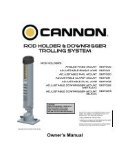
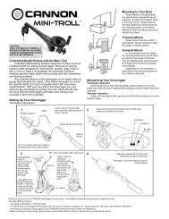
ATTACHING THE ROD HOLDER<br />
Attaching the Rod Holder<br />
The positive lock rod holder incorporates a<br />
locking disk that allows the rod holder to be<br />
aligned in 15 degree increments. Slide the rod<br />
holder tube into the clamp to the desired position<br />
within the recommended area (see below).<br />
Be sure the angled shoulders are facing up.<br />
Place the locking disk into the mating recess of<br />
the frame.<br />
Slip the clamp arms in place where the<br />
obround tab on the disk fits into the slot on the<br />
clamp. Slide the star washer between the arm of<br />
the clamp and the frame. Place the flat washer<br />
onto the bolt. Then insert the bolt with washer<br />
through the clamp by entering the disk, going<br />
through the frame, the star washer, and out the<br />
other side of the clamp. Tighten the nut to secure<br />
the rod holder. Reposition the rod holder by<br />
loosening the nut and adjusting the tilt.<br />
CAUTION: This rod holder is intended for use<br />
of up to 30 lb. test line only, and is not<br />
recommended for use with any tackle IGFA<br />
rated higher than 30 lb. A safety strap (not<br />
included) is recommended for all applications.<br />
The rod holder assembly is not warranted<br />
when used with tackle above 30 lbs.<br />
Equipment placed in the rod holders and the<br />
loss thereof is the responsibility of the user<br />
and is in no way warranted by JOHNSON<br />
OUTDOORS MARINE ELECTRONICS, INC..<br />
Mounting must be in acco<strong>rd</strong>ance with the<br />
above instructions and diagram to be<br />
warranted.<br />
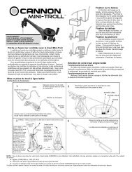
Mise en place du treuil à ligne lestée<br />
Fixation du bras<br />
Le bras s’insère dans le cadre du treuil. Vous<br />
devez vous assurer que le bras est maintenu<br />
solidement en l’appuyant fermement contre<br />
l’épaulement à l’intérieur du cadre et en serrant la vis<br />
de blocage du bras (vis autotaraudeuse de #8 x 1 po)<br />
de manière à ce qu’elle entre dans le trou sur le bras.<br />
La vis Phillips de ¾ po<br />
doit être insérée dans<br />
le trou du bras<br />
Fixation de votre treuil à ligne lestée<br />
Assemblage de la tête pivotante sur le bras<br />
Étalez les plaques latérales de la tête pivotante et<br />
faites glisser l’assemblage par dessus l’extrémité du<br />
bras. Enclenchez l'assemblage et installez deux vis de<br />
#4 x 1/2 po dans la tête pivotante.<br />
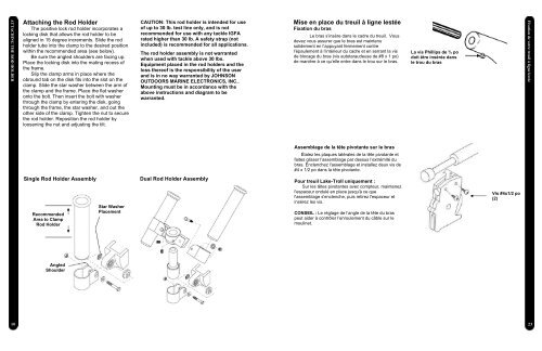
Single Rod Holder Assembly<br />
Recommended<br />
Area to Clamp<br />
Rod Holder<br />
Star Washer<br />
Placement<br />
Dual Rod Holder Assembly<br />
Pour treuil Lake-<strong>Troll</strong> uniquement :<br />
Sur les têtes pivotantes avec compteur, maintenez<br />
l'espaceur ondulé en place jusqu'à ce que<br />
l'assemblage s'enclenche, puis retirez l'espaceur et<br />
insérez les vis.<br />
CONSEIL : Le réglage de l’angle de la tête du bras<br />
peut aider à contrôler l’enroulement du câble sur le<br />
moulinet.<br />
Vis #4x1/2 po<br />
(2)<br />
Angled<br />
Shoulder<br />
10<br />
23