UNI-TROLL & EASI-TROLL - Cannon Downriggers
UNI-TROLL & EASI-TROLL - Cannon Downriggers
UNI-TROLL & EASI-TROLL - Cannon Downriggers
- No tags were found...
Create successful ePaper yourself
Turn your PDF publications into a flip-book with our unique Google optimized e-Paper software.
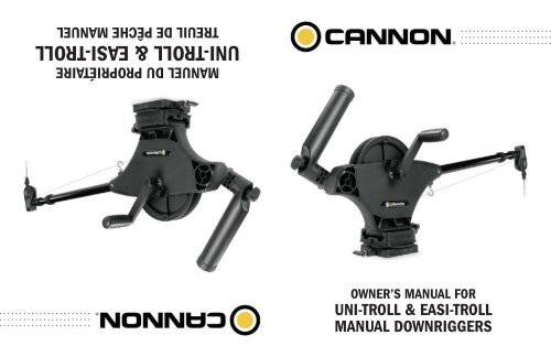
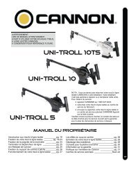
MANUEL DU PROPRIÉTAIRE<strong>UNI</strong>-<strong>TROLL</strong> & <strong>EASI</strong>-<strong>TROLL</strong>TREUIL DE PÊCHE MANUELOWNER’S MANUAL FOR<strong>UNI</strong>-<strong>TROLL</strong> & <strong>EASI</strong>-<strong>TROLL</strong>MANUAL DOWNRIGGERS
2Coup en arrière p. 13Déclencheur de Ligne p. 12Terminer le câble du treuil à ligne lestée p. 12Fixation des supports de cannes à pêche p. 11Crank Handles p. 10Poulie d’extrémité de bras p. 9Bras et du crochet à boule p. 8Mounting p. 6-7Installation p. 6Aperçu du Produit p. 5Table des matièresGarantie / Service d’information p. 4Introduction p. 3TABLE DES MATIÈRES.................................................................................................................................................2CONTENTS.................................................................................................................................................Introduction p. 3Warranty / Service Information p. 4Product Overview p. 5Installation p. 6Mounting p. 6-7Boom and Ball Hook p. 8Boom End Assembly p. 9Crank Handles p. 10Rod Holders p. 11Cable Termination p. 12Line Release p. 12Blowback Calculations p. 13Parts Lists p. 14Easi-Troll ST p. 14-15Easi-Troll ST/E p. 16-17Uni-Troll 5 ST p. 18-19Uni-Troll 5 ST/E p. 20-21Uni-Troll 10 STX p. 22-23Uni-Troll 10 STX/E p. 24-25Uni-Troll 10 STX-TS p. 26-27Uni-Troll 10 STX-TS/E p. 28-29Table of Contents
4Certains états n’autorisent pas les limitations sur la durée de la garantietacite ou sur l’exclusion ou les limitations des dommages indirects, parconséquent les limitations ou les exclusions ci-dessus peuvent ne pass’appliquer dans votre cas. Cette garantie vous donne des droits spécifiques reconnus par la loi et possiblement d’autres droits selon l’état.IL N’EXISTE AUCUNE GARANTIE EXPRESSE À PART CES GARAN-TIES LIMITÉES. JOHNSON OUTDOORS MARINE ELECTRONICS,INC. NIE TOUTE RESPONSABILITÉ POUR LES DOMMAGES ACCES-SOIRES ET INDIRECTS ET EN AUCUN CAS, UNE GARANTIE TACITE(SAUF POUR LE BRAS, LES MOULINETS ET TOUTES LES PIÈCESEN LEXAN®*), INCLUANT TOUTE GARANTIE TACITE DE QUALITÉMARCHANDE OU D’ADAPTABILITÉ À UN BUT EN PARTICULIER, SEPROLONGERA AU-DELÀ D’UN AN À PARTIR DE LA DATE D’ACHAT(ET DANS LE CAS DES COUVRE-BOTTES, VÊTEMENTS, LIGNEEN DACRON, ÉLASTIQUES, GOUPILLE DE SÉCURITÉ PIVOTANTE,POIDS ET CÂBLE MÉTALLIQUE, JOHNSON OUTDOORS MARINEELECTRONICS, INC. NIE TOUTES GARANTIES TACITES). CE DOCU-MENT CONSTITUE L’ENTENTE ENTIÈRE CONCLUE ENTRE LESPARTIES EN CE QUI CONCERNE LE SUJET DES PRÉSENTES; AU-CUNE EXONÉRATION NI AUCUNE MODIFICATION NE SERA VALIDEÀ MOINS QU’UNE COPIE ÉCRITE SOIT SIGNÉE PAR JOHNSONOUTDOORS MARINE ELECTRONICS, INC..LIMITATION ET EXCLUSION DES GARANTIES TACITES ET DE CER-TAINS DOMMAGESLorsque tout défaut, problème, perte ou dommage est survenu à la suited’un accident, d’un abus, de négligence, ou d’usage anormal ou de toutdéfaut de fournir un entretien raisonnable et nécessaire conformémentaux instructions dans le manuel du propriétaireLorsque le produit a été connecté, installé, combiné, altéré, réglé,entretenu, réparé ou manipulé d’une manière qui diffère des instructionsfournies avec le produitEXCLUSIONSCette garantie ne s’applique pas dans les circonstances suivantes :2) Tous les autres composants auront une garantie limitée d’unan à partir de la date d’achat au détail d’origine, à l’exceptiondes ARTICLES SUIVANTS QUI NE COMPORTENT AUCUNEGARANTIE : couvre-bottes, vêtements, ligne en Dacron, élastiques,goupille de sécurité pivotante, poids et câble métallique.Cette garantie limitée peut être appliquée seulement parl’acheteur d’origine; tous les acheteurs subséquents acquièrentle produit « tel quel » sans garantie limitée. La réparation oule remplacement du produit tel qu’indiqué dans cette garantielimitée constitue le recours unique et exclusif de l’acheteurd’origine et la responsabilité unique et exclusive de JohnsonOutdoors Marine Electronics, Inc. en cas de rupture de cettegarantie.Garantie / Service d'information1) Le bras, les moulinets et toutes les pièces incluant, sans s’y restreindre,les cadres et les bases pour qu’ils soient exempts detout défaut de fabrication et de main-d’œuvre lorsqu’ils sont exposésà une usure normale, pour la durée de vie de l’acheteurd’origine.GARANTIE LIMITÉE CANNON®.............................................................................................Johnson Outdoors Marine Electronics, Inc. garantit à l’acheteur d’origineque si le produit en question (voir les exclusions ci-dessous) présenteun défaut de fabrication ou de main-d’œuvre durant les périodes degarantie suivantes, Johnson Outdoors Marine Electronics, Inc. déciderade réparer ou de remplacer sans frais (aucun remboursement en argentne sera effectué) :4POLITIQUE SUR L’ENTRETIEN DE CANNON®..................................................................................APRÈS L’EXPIRATION DE LA PÉRIODE DE GARANTIE AP-PLICABLEAprès l’expiration de la période de garantie applicable, ou sil’une des exclusions ci-dessus s’applique, les produits <strong>Cannon</strong>®seront réparés et facturés pour les pièces et la main-d’œuvre.Toutes les réparations du fabricant réalisées après l’expirationde la période de garantie applicable portent une garantie limitéede 90 jours sous réserve des exclusions et limitations énoncéesci-dessus.POUR FAIRE VALOIR LA GARANTIE OU POUR OBTENIRDES RÉPARATIONS APRÈS L’EXPIRATION DE LA GARAN-TIEPour obtenir un entretien sous garantie aux États-Unis, letreuil ou le composant considéré comme étant défectueux etla preuve d’achat d’origine (incluant la date d’achat) doiventêtre présentés à un centre de service autorisé <strong>Cannon</strong>® ouau centre de service du fabricant <strong>Cannon</strong>® à Mankato, MN.À l’exception de ce qui est indiqué ci-dessous, tous les fraisencourus pour les appels de service, le transport ou la livraisonà destination ou en provenance du Centre de service autorisé<strong>Cannon</strong>® ou de l’usine <strong>Cannon</strong>®, la main-d’œuvre pour lofer,enlever, réinstaller ou regréer les produits pour le service sousgarantie, ou tout autre article similaire sont la responsabilitéunique et exclusive de l’acheteur. Les treuils à ligne lestéeachetés à l’extérieur des États-Unis (ou les composants de cestreuils) doivent être retournés franco de port avec la preuved’achat (incluant la date d’achat et le numéro de série) à uncentre de service autorisé <strong>Cannon</strong>® dans le pays où l’achat aété effectué. Le service sous garantie peut être offert en contactantun centre de service autorisé <strong>Cannon</strong>® fi gurant sur la listeci-jointe ou en contactant l’usine par téléphone au 1 800 2276433 ou par télécopieur au 1 800 527 4464. Si les réparationsrequises sont couvertes par la garantie, nous paierons les fraisde retour à toute destination situé à l’intérieur des États-Unis.VOUS NE DEVEZ PAS retourner votre treuil <strong>Cannon</strong> ® ou sescomposants à votre détaillant. Votre détaillant n’est pas autoriséà réparer ou à remplacer ces composants.Les composants principaux comme et le cadre principal doiventêtre retournés à Johnson Outdoors Marine Electronics, Inc. àMankato, Minnesota, ou à un centre de service autorisé <strong>Cannon</strong>® , pour la réparation ou le remplacement. Pour réduire lescoûts d’expédition, nous vous suggérons d’enlever les piècesamovibles comme le bras et les supports de cannes à pêche.Les petites pièces qui s’enlèvent facilement comme la poignéeet/ou le compteur peuvent être détachées du treuil et envoyéespour leur réparation ou remplacement.Conservez votre reçu ! Une preuve d’achat doit accompagnertout produit retourné.Adresse de retour :<strong>Cannon</strong>121 Power DriveMankato, MN 56001POUR VOTRE INFORMATION :Nº de sérieDate d’achatDétaillantCANNON LIMITED WARRANTY................................................................................................................Johnson Outdoors Marine Electronics, Inc. warrants to the originalpurchaser that if the accompanying product (see exclusions below)proves to be defective in material or workmanship within the followingwarranty periods, Johnson Outdoors Marine Electronics, Inc. will, atits option, either repair or replace same without charge (but no cashrefunds will be made):1) The boom and reels, plus all composite parts, including but notlimited to frames and bases, will be free from defects in materialsand workmanship, subject to normal wear and tear, for theoriginal purchaser’s lifetime.2) All other items will have 1-year limited warranties from thedate of original retail purchase, except THE FOLLOWINGITEMS THAT HAVE NO WARRANTY WHATSOEVER: bootcovers, clothing, Dacron line, rubber bands, swivel lock pin,weights, and wire cable.This limited warranty may be enforced only by the original purchaser;all subsequent purchasers acquire the product “as is”without any benefi t of this limited warranty. Repair or replacementof the product as set forth in this limited warranty shallbe the original purchaser’s sole and exclusive remedy andJohnson Outdoors Marine Electronics, Inc.’ sole and exclusiveliability for breach of this warranty.EXCLUSIONSThis warranty does not apply in the following circumstances:• When the product has been connected, installed, combined,altered, adjusted, serviced, repaired, or handled in a mannerother than according to the instructions furnished with theproduct• When any defect, problem, loss, or damage has resulted fromany accident, misuse, negligence, carelessness, or abnormaluse, or from any failure to provide reasonable and necessarymaintenance in accordance with the instructions of the owner’smanualLIMITATION AND EXCLUSION OF IMPLIED WARRANTIES ANDCERTAIN DAMAGES................................................................................................................THERE ARE NO EXPRESS WARRANTIES OTHER THAN THESELIMITED WARRANTIES. JOHNSON OUTDOORS MARINE ELEC-TRONICS, INC. DISCLAIMS LIABILITY FOR INCIDENTAL ANDCONSEQUENTIAL DAMAGES, AND IN NO EVENT SHALL ANY IM-PLIED WARRANTIES (EXCEPT ON THE BOOM, REELS, AND ALLCOMPOSITE PARTS), INCLUDING ANY IMPLIED WARRANTY OFMERCHANTABILITY OR FITNESS FOR PARTICULAR PURPOSE,EXTEND BEYOND ONE YEAR FROM THE DATE OF PURCHASE(AND IN THE CASE OF THE BOOT COVERS, CLOTHING, DACRONLINE, RUBBER BANDS, SWIVEL LOCK PIN, WEIGHTS, AND WIRECABLE, JOHNSON OUTDOORS MARINE ELECTRONICS, INC.DISCLAIMS ALL IMPLIED WARRANTIES). THIS WRITING CON-STITUTES THE ENTIRE AGREEMENT OF THE PARTIES WITHRESPECT TO THE SUBJECT MATTER HEREOF; NO WAIVER ORAMENDMENT SHALL BE VALID UNLESS IN WRITING SIGNED BYJOHNSON OUTDOORS MARINE ELECTRONICS, INC.Some states do not allow limitations on how long an implied warrantylasts or the exclusion or limitation of consequential damages, so theabove limitation or exclusion may not apply to you. This warranty givesyou specific legal rights, and you may also have other rights that varyfrom state to state.CANNON® SERVICE POLICY................................................................................................................AFTER THE APPLICABLE WARRANTY PERIODAfter the applicable warranty period, or, if one of the above exclusionsapplies, <strong>Cannon</strong> products will be repaired for a charge of parts pluslabor. All factory repairs, after the applicable warranty period, carrya 90-Day Limited Warranty, subject to the exclusions and limitationsstated above.TO ENFORCE WARRANTY OR TO OBTAIN REPAIRS AFTERWARRANTYTo obtain warranty service in the U.S., the downrigger or part believedto be defective and the proof of original purchase (including the date ofpurchase) must be presented to a <strong>Cannon</strong> Authorized Service Centeror to <strong>Cannon</strong>’s factory service center in Mankato, MN. Except asnoted below, any charges incurred for service calls, transportation orshipping/freight to/from the <strong>Cannon</strong> Authorized Service Center or <strong>Cannon</strong>’sfactory, labor to haul out, remove, re-install or re-rig productsfor warranty service, or any similar items are the sole and exclusiveresponsibility of the purchaser. <strong>Downriggers</strong> purchased outside of theU.S. (or parts of such downriggers) must be returned prepaid withproof of purchase (including the date of purchase and serial number)to any Authorized <strong>Cannon</strong> Service Center in the country of purchase.Warranty service can be arranged by contacting a <strong>Cannon</strong> AuthorizedService Center listed on the enclosed sheet, or by contacting thefactory at 1-800-227-6433 or Fax 1-800-527-4464. If the necessaryrepairs are covered by the warranty, we will pay the return shippingcharges to any destination within the United States.DO NOT return your <strong>Cannon</strong> downrigger or parts to your retailer. Yourretailer is not authorized to repair or replace them.Major parts, such as the main frame, must be returned to JohnsonOutdoors Marine Electronics, Inc. in Mankato, Minnesota, or a <strong>Cannon</strong>Authorized Service Center, for repair or replacement. To reduceshipping costs, we suggest removal of loose parts such as the boomand rod holders. Small parts that can be easily removed such as thehandle and/or the counter, may be removed from the downrigger andreturned for repair or replacement.Retain your sales receipt! Proof of purchase must accompanyproduct when returned.Return Address: <strong>Cannon</strong>121 Power DriveMankato, MN 56001FOR YOUR INFORMATION:Serial No.Date PurchasedStore Where PurchasedRETAIN THIS SECTION FOR YOUR RECORDSProduct Warranty
Product OverviewINTRODUCTION TO CON<strong>TROLL</strong>ED DEPTH FISHING........................................................................................................................................................................Undoubtedly there are many fi shermen familiar with the methods and use of controlled depth fi shing. During themid 1960’s the state of Michigan introduced Pacifi c salmon into the Great Lakes in an attempt to revitalize its sportfi shing industry. From this successful transplant, new fi shing techniques and equipment were developed. One suchmethod was controlled depth fishing which enabled fi shermen to place a lure at a desired depth by utilizing downriggers.Because of the varying factors (water temperature, thermocline, weather, tides, time of day, or time of year) it isnecessary for successful fi shing to maintain specifi c water depths that coincide with fi sh movements and feedingpatterns.One essential feature of the downrigger is the depth meter or gauge that indicates lure depth. This allows the anglerto control as well as return to specifi c depths where fi sh have been caught.Due to the success of controlled depth fi shing, downriggers are now being used throughout the world to catch awide variety of species in both fresh and salt water. Whether fishing for blues off Rhode Island, walleyes in LakeErie, sailfi sh off the coast of Florida, or stripers in Tennessee, the use of downriggers will make your fi shing moresuccessful and more enjoyable.3216745PARTS DESCRIPTION1. Reel This is used to spool the cable, available in lengths ranging from 150 to 400 feet.2. Boom This is used to extend the weight out from the body of the downrigger and has a pulley fi xedto its end. Boom lengths range from 24 to 53 inches.3. Swivel Head This relays the cable at the end of the boom to lower the weight.4. Cable This connects to the weight. Cable material is 150 lb. test stainless steel cable.5. Mounting Base This attaches to the boat, enabling you to place the downrigger where you choose.6. Rod Holder This holds your fi shing rods while trolling and may also be used for storing rods.57. Boom Clamps These lock the boom sections together after the boom has been extended or retracted.www.cannondownriggers.comINTRODUCTION À LA PÊCHE EN HAUTE MER CONTRÔLÉE........................................................................................................................................................................Sans aucun doute, il existe de nombreux pêcheurs qui sont familiers avec les méthodes et les activités de la pêche en hautemer. Au milieu des années 60, l’état du Michigan a introduit le saumon du Pacifique dans les Grands Lacs afin de revitaliserl’industrie de la pêche de loisir. Dans la foulée de cette transplantation réussie, de nouvelles techniques et de nouveauxéquipements de pêche ont été mis au point. Une des nouvelles méthodes a été la pêche en haute mer contrôlée qui permet aupêcheur d’aller porter le leurre à la profondeur voulue à l’aide d’un treuil à ligne lestée.À cause de divers facteurs (température de l’eau, thermocline, climat, marée, heure du jour ou période de l’année), il est nécessairepour réussir à pêcher de garder le leurre à des profondeurs spécifiques qui coïncident avec les mouvements des poissonset les habitudes d’alimentation.Une caractéristique importante du treuil à ligne lestée est le profondimètre qui permet de mesurer la profondeur du leurre. Ilpermet au pêcheur de contrôler la profondeur et de retourner à des profondeurs spécifiques où des poissons ont été trouvésprécédemment.En raison du succès de la pêche en haute mer contrôlée, les treuils à ligne lestée sont maintenant utilisés dans le monde entierpour pêcher une grande variété d’espèces en eau douce et en eau de mer. Que vous soyez à la pêche au tassergal près deRhode Island, au doré jaune sur le lac Érié, au voilier sur la côté de la Floride ou au bar rayé au Tennessee, vous aurez plus desuccès et de plaisir si vous utilisez un treuil à ligne lestée.2361475DESCRIPTION DES PIÈCES........................................................................................................................................................................1. Moulinet Il sert à embobiner le câble qui est offert en longueur allant de 46 à 122 m (150 à 400 pi).2. BrasIl sert à distancer le poids du treuil à ligne lestée et il comporte une poulie à son extrémité.Les longueurs des bras varient entre 61 et 135 cm (24 et 53 po).3. Tête pivotante Elle relais le câble à l’extrémité du bras afi n d’abaisser le poids.4. Câble Il est relié au poids. Il s’agit d’un câble de contrôle en acier inoxydable de 60 kg (150 lb).5. Socle de fixation Il est fi xé au bateau et il vous permet de placer le treuil à ligne lestée à l’endroit voulu.6. Support de cannes à pêche7. Brides de brasIl sert à tenir vos cannes à pêche pendant la pêche à la traîne et aussi à entreposer lescannes à pêche.Celles-ci bloquent l'ensemble des sections du bras après une manœuvre d'extension oude rétraction du bras.5www.cannondownriggers.comAperçu du Produit
6Arrows Indicate TypicalMounting LocationsEn raison de la grande variété de bateaux disponibles, la fi xation de votre treuil à ligne lestée peut causer undilemme. Il est essentiel d’avoir les accessoires de fi xation appropriés. <strong>Cannon</strong> offre une gamme complèted’accessoires de fixation pour vous aider à fixer votre treuil à ligne lestée sur tous les types de bateau.InstallationFIXATION DU TREUIL À LIGNE LESTÉE SUR LES BATEAUX........................................................................................................................................................................Un treuil à ligne lestée doit être fi xé à un endroit où il sera facile de l’utiliser et de l’observer. Vous voulez être capabled’observer votre canne à pêche et de réagir rapidement. Ainsi, le choix de l’emplacement de votre treuil à ligne lestéesur votre bateau compte pour 99 % du travail.DOWNRIGGER MOUNTING ON BOATS........................................................................................................................................................................A downrigger should be mounted wherever it is easy to operate and observe. You want to be able to seeyour fishing rod and to react quickly. So,choosing a good location to mount your downrigger on your boatis very important.Due to the great variety of boats available,mounting your downrigger can be a difficult decision. <strong>Cannon</strong>has a complete line of mounting and fishing accessories to aid in your fishing experience. Before makingany permanent changes to your boat consider what accessories might be used in your application.6Arrows Indicate TypicalMounting LocationsInstallation
INSTALLING THE BASE ON YOUR BOAT...........................................................................................InstallationDecks up to7/16” ThickDECKS UP TO 7/16” THICKWhere access to the underside of the deck is notavailable, the mounting base can be mounted usingwellnuts. Use the base as a template to mark locationsand drill four wellnut clearance holes. Mount the baseusing four 1/4-20 x 1-1/2” truss head screws and fourwellnuts. Tighten the screws so the wellnuts are fi rmlycompressed as pictured.Decks ThickerThan 7/16” ThickDECKS THICKER THAN 7/16”For decks thicker than 7/16”, or where the underside ofthe deck is accessible, mount the base with screws, nuts,and washers. Use the base as a template to mark thelocations and drill four 9/32” holes. Use four 1/4-20 x 2”truss head screws and four each fl at washers and nuts.Fasten the base to the deck as pictured.NOTE: Wellnuts SHOULD NOT be used on decksthicker than 7/16”.DECKS THINNER THAN 1/4”Use a <strong>Cannon</strong> deck plate (PN 2200693) to prevent defl ection and add stability to decks thinner than 1/4”. Usethe deck plate as a template to mark the hole locations.If access to the underside of the deck is not available, the deck plate can be mounted using screws and wellnuts.Use the deck plate as a template to mark locations and drill 4 wellnut clearance holes. Use four 1/4-20 x 1-1/2”fl at head screws and four wellnuts to mount deck plate. Tighten the screws so the wellnuts are fi rmly compressed.Where the underside is accessible, the deck plate can be mounted using screws, nuts, and washers. Drill 9/32”holes. Use four 1/4-20 x 1-1/2” flat head screws, nuts and washers (fl at and lock). Fasten plate to deck. To securethe mounting base to the deckplate use four 1/4-20 x 1” truss head screws.NOTE: When using the telescopic boom, we strongly recommend the use of a deck plate on all boats toprovide adequate stability for the downrigger.LOW-PROFILE SWIVEL BASEThe Low-Profi le Swivel Base mounting follows the same procedureas for the deck plate except that four 1/4”-20 x 1-1/2” truss headscrews are used to fasten the mounting base and four additional1/4”-20 x 2” truss head screws fix the swivel base to the boat deck.7www.cannondownriggers.comINSTALLATION DE LA BASE SUR VOTRE BATEAU..........................................................................................................PONTS JUSQU’À 7/16 PO D’ÉPAISSEURSi l’accès à la sous-face du pont n’est pas possible, labase peut être installée à l’aide d’écrous-douilles. Utilisezla base comme gabarit pour marquer l’emplacement etpercez quatre trous de 1/2 po. Fixez la base à l’aide dequatre vis à tête bombée large de 1/4-20 x 4 po et dequatre écrous-douilles. Serrez les vis pour que les écrousdouillessoient comprimés solidement, tel que montré.Decks up to7/16” ThickPONTS D’UNE ÉPAISSEUR SUPÉRIEURE À 7/16 POPour les ponts d’une épaisseur supérieure à 7/16 po, ou dontl’accès à la sous-face est accessible, fi xez la base avec les vis,écrous et rondelles. Utilisez la base comme gabarit pour marquerl’emplacement et percez quatre trous de 9/32 po. Utilisez quatrevis à tête bombée large de 1/4-20 x 4 po et quatre rondellesplates, quatre rondelles de frein et quatre écrous. Serrez la basesur le pont, tel que montré.Decks ThickerThan 7/16” ThickNOTA : Les écrous-douilles ne peuvent pas être utiliséssur des ponts d’une épaisseur supérieure à 7/16 po.PONTS D’UNE ÉPAISSEUR INFÉRIEURE À 1/4 POUtilisez une plaque de pont <strong>Cannon</strong> pour prévenir la courbure et procurer plus de stabilité aux quais d’une épaisseur inférieureà 1/4 po. Utilisez une plaque de pont comme gabarit pour marquer l’emplacement des trous.Si l’accès à la sous-face du pont n’est pas possible, la plaque de pont peut être installée à l’aide de vis et d’écrous-douilles.Percez des trous de 1/2 po. Utilisez quatre vis à tête fraisée de 1/4-20 x 2 po et quatre écrous-douilles pour installer la plaquede pont, tel que montré. Serrez les vis pour que les écrous-douilles soient comprimés solidement.Si la sous-face est accessible, la plaque de pont peut être fixée à l’aide de vis, d’écrous et de rondelles. Percez des trous de9/32 po. Utilisez un ensemble de fi xation de la plaque de pont <strong>Cannon</strong> comprenant quatre vis à tête fraisée 1/4-20 x 2 po,des écrous et des rondelles (plates et de frein). Fixez la plaque au pont, tel que montré. Pour attacher solidement la base à laplaque de pont, utilisez quatre vis à tête bombée large de 1/4-20 x 2 po.NOTA : Si vous utilisez un bras télescopique, nous vous recommandons fortement d’utiliser une plaque de pont sur tous lesbateaux pour stabiliser le treuil à ligne lestée adéquatement.LA BASE PIVOTANTE À PROFIL BASLa procédure de fi xation de la base pivotante à profi l bas est la même quecelle de la plaque de pont, sauf que quatre vis à tête bombée large de1/4 po-20 x 2 1/2 po sont utilisées pour fi xer la base et quatre vis à tête bombéelarge supplémentaires de 1/4 po-20 x 2 1/2 po servent à fi xer la basepivotante au pont du bateau.7www.cannondownriggers.comInstallation
FIGURE 48FIGURE 3Pour régler la longueur du bras (en ayant le bras étenduloin de vous), tournez les brides (voir l’élément n° 7 sur lapage 5) environ un quart de tour dans le sens antihorairepour déverrouiller et glissez la section du bras vers laposition désirée. Une fois en place, verrouillez les bridesen tournant dans le sens horaire jusqu’à ce qu’elles soientserrées.FIGURE 2***BRAS TÉLESCOPIQUE SEULEMENT***4) Insérez un boulon 1/4-20 x 2 po dans le nez du cadredu côté du moulinet. À l’aide d’un tournevis cruciforme,enfi lez le boulon dans le contre-écrou de nylon mentionnéà l’étape 3. Serrez le boulon jusqu’à voir son extrémitéalignée avec le haut de l’écrou. (Figure 4)3) Insérez le contre-écrou de nylon 1/4-20 dans la pochehexagonale sur le nez du cadre. (Figure 3)FIGURE 12) Retirez le boulon 1/4-20 x 2 po et le contre-écrou denylon 1/4-20 du sac de quincaillerie fourni. (Figure 2)1) Introduisez le bras dans le cadre (Figure 1) et alignezles trous du bras avec les trous du cadre. Remarque :les modèles Easi-Troll nécessitent l’adaptateur de brasfourni.InstallationINSTALLATION DU BRASET DU CROCHET À BOULE............................................................................................INSTALLING THE BOOM AND BALL HOOK............................................................................................1) Insert boom into frame (Figure 1) and line upholes in boom with holes in frame. Note:Easi-Troll units require the included boom adapter.2) Remove 1/4-20 x 2” bolt and 1/4-20 nylon locknutfrom included hardware bag assembly. (Figure 2)3) Insert the 1/4-20 nylon locknut into the hex pocketon the nose of the frame. (Figure 3)4) Insert 1/4-20 x 2” bolt into reel side of frame nose.With a Phillips head screw driver, thread bolt into nylonlocknut from step 3. Tighten bolt until the end of thebolt is fl ush with the top of the nut. (Figure 4)8**TELESCOPIC BOOM ONLY**To adjust the boom length (with the boom extendingaway from you) rotate the clamps (See item # 7 onpage 5) approximately ¼ turn counter-clockwise tounlock and slide the boom section to the desired position.Once in place, lock the clamps by rotating clockwise untiltight.FIGURE 1FIGURE 2FIGURE 3FIGURE 4Installation
InstallationBOOM END PULLEY.........................................................................................Telescopic Boom1) Remove boom end assembly from hardware bag.2) Remove #8 self tapping screw from hardware bag.3) Insert boom end post into end of the small tube of thetelescopic boom assembly. (Figure 5)4) Align hole in boom post with hole in small end tube.5) Secure boom end with #8 screw as shown. Tightenwith Phillips head screw driver by rotating clockwiseuntil tight. (Figure 6)9www.cannondownriggers.comFIGURE 5FIGURE 6FIGURE 5FIGURE 6POULIE D’EXTRÉMITE DE BRAS.........................................................................................Bras télescopique1) Prenez l'ensemble d'extrémité de bras du sac dequincaillerie.2) Prenez la vis autotaraudeuse #8 du sac de quincaillerie.3) Insérez la colonne d'extrémité du bras dans le boutdu petit tube de l'ensemble du bras télescopique.(Figure 5)4) Alignez le trou de la colonne du bras avec le trou dubout de tube.5) Fixez l'extrémité du bras à l'aide de la vis #8, commeillustré. Serrez à l'aide du tournevis cruciforme.(Figure 6)9www.cannondownriggers.comInstallation
10Poignée de la manivelleCoursesRessortPalier de butéeNOTA : Placez votre doigt sur le bord du palier et des courses. Cela permet d’enfiler la manivelle plus facilement jusqu’à ceque le ressort exerce une tension sur le patin d’embrayage.Installation........................................................................................................................................................................Assurez-vous que le palier de butée est bien intercalé entre ses deux courses. Le côté étroit du ressort du palier de butéedoit être installé en direction du palier. Glissez le palier avec les courses et le ressort par-dessus l’arbre de rochet. Ensuite,faites passer avec précaution la poignée de manivelle sur l’arbre et tournez la poignée dans le sens horaire jusqu’à ce quel’embrayage soit complètement serré.FIXATION DE LA POIGNÉE DE LA MANIVELLEATTACHING THE CRANK HANDLE ASSEMBLY........................................................................................................................................................................Make sure the thrust bearing is sandwiched between its two races. The thrust bearing spring should be orientedwhere the narrow end is toward the bearing. Slide the bearing with races and spring over the ratchet shaft. Then,carefully thread the crank handle onto the shaft and continue turning the handle clockwise until the clutch is fullytightenedNOTE: Place your fi ngertip on the edge of the bearing and races. This allows the crank to be threaded more easilyuntil the spring puts resistance on the clutch pad.Thrust BearingSpringRacesCrank HandleInstallation10
InstallationATTACHING THE ROD HOLDER(S).........................................................................................The locking rod holder(s) incorporate a locking toothdesign which can be easily adjusted every 15° with thesoft grip knob. **The unique two piece design allowsindependent adjustment of the rod holder and the rodholder arm in two axes. (Figure 7)FIGURE 7Caution: This rod holder is intended for use of up to 30lb. test line only and is not recommended for use withany tackle IGFA (International Game Fish Association)rated higher than 30 lb. A safety strap (not included) isrecommended for all applications.NOTE: The rod holder assembly is not coveredunder warranty when used with tackle above 30 lbs.Equipment placed in the rod holders and the lossthereof is the responsibility of the user and is in noway warranted by Johnson Outdoors, Inc. Mountingmust be in accordance with the above instructionsand pictures to comply with the product warranty.To install the rod holder(s):1) **Fasten rod holder to rod holder elbow usingsupplied spring and knob. (Figure 8)FIGURE 82 ) Attach the rod holder to the downrigger on the leftside using the supplied spring and knob. (Figure 9)The rod holder can be adjusted by loosening theknob until the locking teeth are free from each other.Rotate the rod holder or arm to the desired position andre-tighten knob.**Not applicable for Easi-Troll models.FIGURE 911www.cannondownriggers.comFIXATION DU/DES SUPPORT(S)DE CANNES À PÊCHE.........................................................................................Le(s) support(s) de canne à pêche à verrouillageintegrè (nt) un modèle de dent de verrouillage qui peutêtre facilement réglé par incréments de 15° à l'aide dubouton de la poignée à revêtement souple. **La conceptionunique à deux pièces facilite le réglage séparé dusupport de canne à pêche dt du bras de ce support endeux aces. (Figure 7)Attention: Ce support de canne à pêche est destinéà être utilisé avec une ligne de 30 livres uniquementet n'est pas recommandé pour une utilisation avecn'importe quel agrès IGFA (Internaional Game Fish Association)calibré à plus de 30 livres. L'utilisation d'uneattache de sécurité (non incluse) est recommandéepour toutes les applications.Nota: L'ensemble du support de canne à pêche n'estpas couvert par la garantie s'il est utilisé avec un agrèsde plus de 30 livres. L'equipement placé dans le supportde canne à pêche et la perte de celui-ci est la responsabilitéde l'utilisateur et n'est en aucun cas garantit parJohnson Outdoors, Inc. Le montage doit se faire suivantles instructions et images susmentionnées pour seconformer à la garantie du produit.Pour installer le(s) support(s) de canne à pêche:1) **Fixez le support de canne à pêche à son coude enutilisant le bouton à ressort fourni.2 ) Fixez le support de canne à pêche au treuil à lignelestée sur le côté gauche en utilisant le bouton à ressortfourni. (Figure 9)Le support de canne à pêche peuvent étre réglés endesserrant l'un des boutons jusqu'à libérer la dent deverrouillage. Faites piooter le support de canne à pêcheou le bras vers la position souhaitée et resserrez lebouton.** Non applicable pour Easi-Troll modèles.FIGURE 7FIGURE 8FIGURE 911www.cannondownriggers.comInstallation
12InstallationTERMINATING THE DOWNRIGGER CABLE........................................................................................................................................................................Cache en caoutchoucCâbleDéroulez environ 2 pi de câbleet faites-le passer dans lecache en caoutchouc.Examinez la partie supérieure du terminator etnotez l’ordre détaillé pour faire passer le câble.ENTRÉE CÂBLEENTRÉE CÂBLEAttachez auterminator.SORTIEÉmerillonagrafeConseil: nous vous recommandonsd’utiliser des pinces coupe-fil pourprocéder à cette partie du montage.Faites passerle câble dans leTROU A.Faites entrer sixpo de câble àl’intérieur. Faitespasser le câbleà l’intérieur de latête pivotante, puisdans la partie inférieuredu terminator.Faites sortir lecâble par le TROUB et faites-le passerdans le TROU C.Poussez le câblejusqu’à ce que sonextrémité entreen contact avecl’intérieur du crochetdu terminator.CONSEIL: Utilisez uniquement un câble droit, le câble ne doit pas êtreTROU Acourbé.Tendez lecâble enappuyant surle terminatorjusqu’àce qu’ilse ferme.Ensuite, tirezen haut et enbas pour tendrele câble.Veillez à ceque le câblepasse dansle crochet.Tête pivotanteGlissez le cache sur la partie supérieuredu terminator et faites un test en tirant surle câble.Le câble servira à attacher un poids pourla pêche <strong>Cannon</strong>.Conseil: Utilisez uniquement un câble droit lors de l'acheminement à travers le terminator. Un câble usé ou courbépeut devenir fatigué et peut se briser prématurément lors de la récupération de poids à la traîne.<strong>UNI</strong>-RELEASE DE CANNON........................................................................................................................................................................Le Uni-Release de <strong>Cannon</strong> s’attache directement surle poids du treuil à ligne lestée. Attachez la ligne surl’attache à l’extrémité du déclencheur et cliquez ensuitepour régler la tension. Le déclencheur peut être utiliséavec n’importe quelle ligne en eau douce ou en eau demer et peut être réglé à une tension de serrage de 1 à10 kg (2 à 22 lb) sur la ligne.FermerOuvrirRégler latensionPour changer la tension de déclenchement de la ligne,tournez le bouton de tension vers (+) pour l’augmenter ouvers (-) pour la réduire. La tension peut aussi varier selonl’emplacement de la ligne dans les pinces. La tension estplus élevée si la ligne est placée vers la charnière et latension est plus basse si la ligne est placée plus près del’ouverture. Pour ouvrir le déclencheur, étalez les brasde déclenchement avec le pouce et l’index en appliquantune pression sur les côtés.OuvrirLigne àpêchePadsTERMINATING THE DOWNRIGGER CABLE........................................................................................................................................................................TIP: Use only straight cable when routing thru the terminator. Worn or kinked cable can be stressedand may break prematurely when retrieving trolling weights.ATTACHING THE LINE RELEASE (<strong>UNI</strong>-RELEASE)........................................................................................................................................................................The <strong>Cannon</strong> Uni-Release attaches directly to thedownrigger weight. Attach fi shing line to the clipat the end of the release, and then click through aseries of increasing tension settings. The releasecan be used with any test line on salt or fresh waterand may be adjusted from 2 to 22 pounds of griptension on the line.To change line release tension, turn tension knobto (+) to increase or (-) to decrease. Tension alsomay vary according to where the line is placed inthe grips. Higher tension is on the line if it is setback toward the hinge, and lower if set closer to theopening. To open the release, spread the releasearms with thumb and forefi nger applying pressureto the sides.Installation12
Blowback ChartsBlowback Calculations8-Lb. Weight at 2, 4, and 6 MPH2 MPH4 MPHBLOWBACK.........................................................................................Simply stated, blowback is what happens to the downriggerweight when you pull it through the water behindyour boat. As your speed increases, so does the horizontaldistance between the weight and your downrigger.The faster you go, the farther the weight is behindyou. The farther the weight is behind you, the shallowerthe weight is.6 MPHActual Depth of Weight (ft.)The following charts provide you with blowback informationfor three sizes of <strong>Cannon</strong> downrigger weights pulledat three different speeds with no lures attached andwith no current. Current drag, water salinity and the useof non-<strong>Cannon</strong> products will affect your actual trollingdepth.Amount of Cable in Water (ft.)10-Lb. Weight at 2, 4, and 6 MPHAs an example, the fi rst chart shows that if you are trollingat 4 MPH with an 8 pound weight and you have 100FT. of cable in the water with no current; the downriggerball is actually at a depth of about 80 FT.2 MPH4 MPH6 MPHActualDepth of Weight (ft.)Amount of Cable in Water (ft.)12-Lb. Weight at 2, 4, and 6 MPH2 MPH4 MPH6 MPHActual Depth of Weight (ft.)13Amount of Cable in Water (ft.)www.cannondownriggers.comCOUP EN ARRIÈRE............................................................................En quelques mots, le coup en arrière est ce qui arriveau poids du treuil lorsque vous le tirez dans l’eauderrière votre bateau. Plus votre vitesse augmente,plus la distance horizontale entre le poids et votretreuil augmente. Plus vous allez vite, plus le poidss’éloigne derrière vous. Plus le poids s’éloigne derrièrevous, plus le poids se rapproche de la surfacede l’eau.Le tableau suivant contient de l’information sur lecoup en arrière pour trois dimensions de poids detreuil <strong>Cannon</strong> qui sont tirés à trois vitesses différentessans leurre et sans courant. La traînée du courant,la salinité de l’eau et l’utilisation de produits nonfabriqués par <strong>Cannon</strong> affecteront votre profondeur lade pêche à la traîne réelle.Par exemple, le premier tableau montre que si vouspêchez à la traîne à une vitesse de 6 km/h (4 mi/h)avec un poids de 4 kg (8 lb), et un câble de 30 m(100 pi) dans l’eau sans courant; la boule du treuilse trouve en fait à une profondeur de 24 m (80 pi)environ.12 livres Poids à 2, 4 et 6 mi/h2 mi/h4 mi/h6 mi/h13www.cannondownriggers.comCoup en arrièreProfondeur du poids réelle (pieds)Profondeur du poids réelle (pieds)Profondeur du poids réelle (pieds)Tableaux concernant le coup arrière8 livres Poids à 2, 4 et 6 mi/h2 mi/h4 mi/h6 mi/hLongueur du câble immergé (pieds)10 livres Poids à 2, 4 et 6 mi/h2 mi/h4 mi/h6 mi/hLongueur du câble immergé (pieds)Longueur du câble immergé (pieds)
Form No. 3397136 Rev B ECN 33050 4/13AVERTISSEMENT : Ce produit contient des produits chimiques considérés par l’état de la Californie comme étant cancérigènes et/ou toxiquespour le système reproducteur.Tous droits réservés 2012 Johnson Outdoors Marine Electronics, Inc.Conforme à 89/336/EEC (EMC) en vertu des normes EN 55022A, EN 50082-2 depuis 1996 LN V9677264Pour télécharger les manuels de produit ou acheter des produits <strong>Cannon</strong> d’un concessionnaire agréé, veuillez visiter notre page Internet àwww.cannondownriggers.com.CONSUMER & TECHNICAL SERVICEJohnson Outdoors Marine Electronics, Inc.121 Power DriveMankato, MN 56001Phone 1-800-227-6433Fax: 1-800-527-4464www.cannondownriggers.comCONSUMER & TECHNICAL SERVICEJohnson Outdoors Marine Electronics, Inc.121 Power DriveMankato, MN 56001Phone 1-800-227-6433Fax: 1-800-527-4464www.cannondownriggers.comTo download product manuals or purchase <strong>Cannon</strong> products from an authorized dealer, please visit our web page atwww.cannondownriggers.com©2012 Johnson Outdoors Marine Electronics, LLC. All rights reserved.Product conforms to EU EMC directive 204/108/EC and Machinery Directive 2006/42/EC.WARNING: This product contains chemical(s) known to the state of California to cause cancer and/or reproductive toxicity.Form No. 3397136 Rev B ECN 33050 4/13
Parts List*bag assembly pas indiqué sur le schéma*bag assembly not shown in diagram3317 3392033 TUBE, DUAL AXIS RD HLDR16 3392010 ASSY, BOOM TELESCOPIC, SS 33 9250003 HDW PIN 3/16 X 7/8 DOWEL * 2294894 BAG ASSEMBLY15 3391955 BASE-MOUNT, MAG ST 32 9100160 DOG RATCHET 48 9010004 HDW BEARING SWIVEL BASE (QTY: 2)14 3390101 KNOB-CANNON, SOFT GRIP 31 9040040 HDW BOLT 1/4-20 ROLLEDTHD HOOK 47 2372100 SCREW, #8-18 X 5/8 (QTY: 2)13 3392228 GEAR REEL (METRIC) 30 3391737 WASHER THRUST, 17-7 SS (qty: 2) 46 2287002 HDW SPRING RELEASE PIN12 3392229 GEAR COUNTER (METRIC) 29 9010280 HDW BEARING, THRUST 45 2277001 HDW RETAINER RELEASE NUT11 3321001 COVER-CLUTCH 28 9010001 BEARING NYLINER 44 2267006 PLATE - INDEXING 6 STOP16NOTES:www.cannondownriggers.com1901141 <strong>UNI</strong>-<strong>TROLL</strong> 10 STX-TS / E10 3320011 COUNTER 3 DIGIT 27 3994210 CRANK ARM/HANDLE ASM 43 2267005 PLATE, BASE (ROUGH)9 2373450 SCREW-#8-18 X 3/8" THRD CUT SS 26 3990200 ASSY-CNN, BOOM END 42 2267002 BRK PLATE SWIVEL8 2287002 HDW SPRING RELEASE PIN 25 3397930 REEL, ROUGH, 3.75" OD SS 41 2266001 HDW PIN RELEASE7 2263103 NUT-1/4-20 NYLOCK SS 24 3395634 DECAL-SIDE, BLACK 40 2249001 HDW KNB RELEASE PIN6 3391710 PAD - CLUTCH 23 3394722 INSERT, PUSH ON 39 2998905 ASSY - CNN SWIVEL BASE5 1264670 ASY CLUTCH PAD SM HOLE 22 3394702 INSERT, BASE, LO-PRO 38 3391904 ASSY-CNN, ROD HOLDER, UT4 1080001 SHAFT REEL ET/UT 21 3394200 ARM, DUAL AXIS-ROD HLDR 37 2200109 SALTWATER LINE RELEASE3 1000904 ASY SHAFT RATCHET UT6 20 3393480 SCREW-#10X1" PPH HI-LO SS 36 3392541 FRAME, MANUAL, DR, WHITE2 3391990 PLATE - CLUTCH/BRAKE REEL 19 3393461 SCREW-1/4-20 X 2" SS, PPH 35 9400070 HDW SPRING DOG1 3391995 PLATE - RATCHET BRAKE 18 3393000 RING, RETAINING, 1/4" SHAFT 34 9400040 HDW SPRING CRANKIn the U.S.A., replacement parts may be ordered directly from CANNON Parts Dept., 121 Power Drive, Mankato, Minnesota 56001. Be sure to provide the MODEL and SERIAL numbersof your downrigger when ordering parts. Please use the correct part numbers from the parts list. Payment for any parts ordered from the CANNON parts department, may be bycash, personal check, Discover Card, MasterCard or VISA. To order, call 1-800-227-6433 or FAX 1-800-527-4464.Si vous résidez aux Éstats-Unis, vous pouvez commander des pièces de rechange directement auprès du service des pièces de rechange de CANNON, 121 Power Drive, Mankato,Minnesota, 56001. Assurez-vous de faire référence au MODELE et aux numéros de SÉRIE de votre treuil lors de la commande de pièces de rechange. Veuillez utiliser les bonsnuméros de référence de la liste des pièces. Le paiement pour toute pièce commandée auprès du service des pièces de rechange de CANNON peut se faire en espèces, par chèquepersonnel, par Discover Card, Master Card ou VISA. Pour vos commandes, veuillez appeler par téléphone le 1-800-227-6433 ou par TÉLÉCOPIEUR 1-800-527-4464
17www.cannondownriggers.com1901141 <strong>UNI</strong>-<strong>TROLL</strong> 10 STX-TS / EParts List32
Parts List*bag assembly pas indiqué sur le schéma*bag assembly not shown in diagram3117 3392223 GEAR, 28 TOOTH16 3392222 GEAR, 56 TOOTH 33 9250003 HDW PIN 3/16 X 7/8 DOWEL * 2294894 BAG ASSEMBLY15 3392033 TUBE, DUAL AXIS RD HLDR 32 9100160 DOG RATCHET 48 9010004 HDW BEARING SWIVEL BASE (QTY: 2)14 3392010 ASSY, BOOM TELESCOPIC, SS 31 9040040 HDW BOLT 1/4-20 ROLLEDTHD HOOK 47 2372100 SCREW, #8-18 X 5/8 (QTY: 2)13 3391955 BASE-MOUNT, MAG ST 30 3391737 WASHER THRUST, 17-7 SS (qty: 2) 46 2287002 HDW SPRING RELEASE PIN12 3390101 KNOB-CANNON, SOFT GRIP 29 9010280 HDW BEARING, THRUST 45 2277001 HDW RETAINER RELEASE NUT11 3321001 COVER-CLUTCH 28 9010001 BEARING NYLINER 44 2267006 PLATE - INDEXING 6 STOPwww.cannondownriggers.com1901020 <strong>EASI</strong>-<strong>TROLL</strong> ST381901140 <strong>UNI</strong>-<strong>TROLL</strong> 10 STX TS10 2373450 SCREW-#8-18 X 3/8" THRD CUT SS 27 3994210 CRANK ARM/HANDLE ASM 43 2267005 PLATE, BASE (ROUGH)In the U.S.A., replacement parts may be ordered directly from CANNON Parts Dept., 121 Power Drive, Mankato, Minnesota 56001. Be sure to provide the MODEL and SERIAL numbersof your downrigger when ordering parts. Please use the correct part numbers from the parts list. Payment for any parts ordered from the CANNON parts department, may be bycash, personal check, Discover Card, MasterCard or VISA. To order, call 1-800-227-6433 or FAX 1-800-527-4464.9 2287002 HDW SPRING RELEASE PIN 26 3990200 ASSY-CNN, BOOM END 42 2267002 BRK PLATE SWIVEL8 2263103 NUT-1/4-20 NYLOCK SS 25 3397930 REEL, SS, 24" RETRIEVE 41 2266001 HDW PIN RELEASE7 3393130 NUT-HEX 1/4-20 SS 300SRS 24 3395634 DECAL-SIDE, BLACK 40 2249001 HDW KNB RELEASE PIN6 3391710 PAD - CLUTCH 23 3394722 INSERT, PUSH ON 39 2998905 ASSY - CNN SWIVEL BASE5 1080001 SHAFT REEL ET/UT 22 3394702 INSERT, BASE, LO-PRO 38 3391904 ASSY-CNN, ROD HOLDER, UT4 1000904 ASY SHAFT RATCHET UT6 21 3394200 ARM, DUAL AXIS-ROD HLDR 37 2200109 SALTWATER LINE RELEASE3 3391990 PLATE - CLUTCH/BRAKE REEL 20 3393480 SCREW-#10X1" PPH HI-LO SS 36 3392541 FRAME, MANUAL, DR, WHITE2 3391995 PLATE - RATCHET BRAKE 19 3393461 SCREW-1/4-20 X 2" SS, PPH 35 9400070 HDW SPRING DOG1 0220477 METER 3 DIGIT 18 3393000 RING, RETAINING, 1/4" SHAFT 34 9400040 HDW SPRING CRANKSi vous résidez aux Éstats-Unis, vous pouvez commander des pièces de rechange directement auprès du service des pièces de rechange de CANNON, 121 Power Drive, Mankato,Minnesota, 56001. Assurez-vous de faire référence au MODELE et aux numéros de SÉRIE de votre treuil lors de la commande de pièces de rechange. Veuillez utiliser les bonsnuméros de référence de la liste des pièces. Le paiement pour toute pièce commandée auprès du service des pièces de rechange de CANNON peut se faire en espèces, par chèquepersonnel, par Discover Card, Master Card ou VISA. Pour vos commandes, veuillez appeler par téléphone le 1-800-227-6433 ou par TÉLÉCOPIEUR 1-800-527-4464Parts List18
Parts List*bag assembly pas indiqué sur le schéma*bag assembly not shown in diagram15 3391955 BASE-MOUNT, MAG ST 30 9010280 HDW BEARING, THRUST14 3390101 KNOB-CANNON, SOFT GRIP 29 9010001 BEARING NYLINER13 3333004 GEAR REEL UT HP 28 3994210 CRANK ARM/HANDLE ASM12 3333003 GEAR COUNTER UT HP 27 3990200 ASY-CNN, BOOM END11 3321001 COVER-CLUTCH 26 3397904 REEL, ROUGH, 5.75" OD10 2373450 SCREW-#8-18 X 3/8" THRD CUT SS (qty: 3) 25 3395906 ADAPTER, BOOM END9 2287002 HDW SPRING RELEASE PIN 24 3395634 DECAL, SIDE, BLACK 39 3391906 ASSY-CNN, ROD HOLDER, ET19www.cannondownriggers.com1901140 <strong>UNI</strong>-<strong>TROLL</strong> 10 STX TS8 2263103 NUT-1/4-20 NYLOCK SS 23 3394722 INSERT, PUSH ON * 2294894 BAG ASSEMBLYIn the U.S.A., replacement parts may be ordered directly from CANNON Parts Dept., 121 Power Drive, Mankato, Minnesota 56001. Be sure to provide the MODEL and SERIAL numbersof your downrigger when ordering parts. Please use the correct part numbers from the parts list. Payment for any parts ordered from the CANNON parts department, may be bycash, personal check, Discover Card, MasterCard or VISA. To order, call 1-800-227-6433 or FAX 1-800-527-4464.7 3393130 NUT-HEX 1/4-20 SS, RIE COATED 22 3394702 INSERT, BASE, LO-PRO 37 2277002A LINE RELEASE1901020 <strong>EASI</strong>-<strong>TROLL</strong> ST6 3391710 PAD - CLUTCH 21 3392033 ROD HOLDER, DUAL AXIS SLEEVE 36 3392540 FRAME, MANUAL DR, BLACK5 1080001 SHAFT REEL ET/UT 20 3393480 SCREW-#10X1" PPH HI-LO SS (qty: 4) 35 9400070 HDW SPRING DOG4 1000904 ASY SHAFT RATCHET UT6 19 3393461 SCREW-1/4-20X2" SS, PPH 34 9400040 HDW SPRING CRANK3 3391990 PLATE - CLUTCH/BRAKE REEL 18 3393000 RING, RETAINING, 1/4" SHAFT 33 9250003 HDW PIN 3/16 X 7/8 DOWEL2 3391995 PLATE - RATCHET BRAKE 17 3392033 TUBE, DUAL AXIS ROD HOLDER 32 9100160 DOG RATCHET1 0220477 METER 3 DIGIT 16 3392017 BOOM, MANUAL DOWNRIGGER 31 9010310 HDW WASHER, THRUST, 410 SS (qty:2)Si vous résidez aux Éstats-Unis, vous pouvez commander des pièces de rechange directement auprès du service des pièces de rechange de CANNON, 121 Power Drive, Mankato,Minnesota, 56001. Assurez-vous de faire référence au MODELE et aux numéros de SÉRIE de votre treuil lors de la commande de pièces de rechange. Veuillez utiliser les bonsnuméros de référence de la liste des pièces. Le paiement pour toute pièce commandée auprès du service des pièces de rechange de CANNON peut se faire en espèces, par chèquepersonnel, par Discover Card, Master Card ou VISA. Pour vos commandes, veuillez appeler par téléphone le 1-800-227-6433 ou par TÉLÉCOPIEUR 1-800-527-4464Parts List30
Parts List*bag assembly pas indiqué sur le schéma*bag assembly not shown in diagram15 3390101 KNOB-CANNON, SOFT GRIP (qty:2) 30 9010280 HDW BEARING, THRUST14 3392226 GEAR REEL (METRIC) 29 9010001 BEARING NYLINER13 3392227 GEAR COUNTER (METRIC) 28 3994210 CRANK ARM/HANDLE ASM12 3321001 COVER-CLUTCH 27 3990200 ASSY-CNN, BOOM END11 3320011 COUNTER 3 DIGIT (METRIC) 26 3395906 ADAPTER, BOOM END10 2373450 SCREW-#8-18 X 3/8" THRD CUT SS (qty:3) 25 3395634 DECAL-SIDE, BLACK 39 3391906 ASSY-CNN, ROD HOLDER, ET21www.cannondownriggers.com1901131 <strong>UNI</strong>-<strong>TROLL</strong> 10 STX / E1901021 <strong>EASI</strong>-<strong>TROLL</strong> ST / E9 2287002 HDW SPRING RELEASE PIN 24 3394722 INSERT, PUSH ON 38 3395906 ADAPTER, BOOM ENDIn the U.S.A., replacement parts may be ordered directly from CANNON Parts Dept., 121 Power Drive, Mankato, Minnesota 56001. Be sure to provide the MODEL and SERIAL numbersof your downrigger when ordering parts. Please use the correct part numbers from the parts list. Payment for any parts ordered from the CANNON parts department, may be bycash, personal check, Discover Card, MasterCard or VISA. To order, call 1-800-227-6433 or FAX 1-800-527-4464.8 2263103 NUT-1/4-20 NYLOCK SS 23 3394702 INSERT, BASE, LO-PRO * 2294894 BAG ASSEMBLY7 3393130 NUT-HEX 1/4-20 SS, RIE COATED 22 3392033 ROD HOLDER, DUAL AXIS SLEEVE 37 2277002A LINE RELEASE6 3391710 PAD-CLUTCH 21 3393480 SCREW-#10-1" PPH HI-LO SS (qty: 4) 36 3392540 FRAME, MANUAL DR, BLACK5 1080001 SHAFT REEL ET/UT 20 3393461 SCREW-1/4-20 X 2" SS, PPH 35 9400070 HDW SPRING DOG4 1000904 ASY SHAFT RATCHET UT6 19 3393000 RING, RETAINING, 1/4" SHAFT 34 9400040 HDW SPRING CRANK3 3391990 PLATE - CLUTCH/BRAKE REEL 18 3392033 TUBE, DUAL AXIS RD HLDR 33 9250003 HDW PIN 3/16 X 7/8 DOWEL2 3391995 PLATE-RATCHET BRAKE 17 3392017 BOOM, MANUAL, DOWNRIGGER 32 9100160 DOG RATCHET1 3397904 REEL ROUGH 16 3391955 BASE-MOUNT, MAG ST 31 3391737 WASHER THRUST, 17-7 SS (qty:2)Si vous résidez aux Éstats-Unis, vous pouvez commander des pièces de rechange directement auprès du service des pièces de rechange de CANNON, 121 Power Drive, Mankato,Minnesota, 56001. Assurez-vous de faire référence au MODELE et aux numéros de SÉRIE de votre treuil lors de la commande de pièces de rechange. Veuillez utiliser les bonsnuméros de référence de la liste des pièces. Le paiement pour toute pièce commandée auprès du service des pièces de rechange de CANNON peut se faire en espèces, par chèquepersonnel, par Discover Card, Master Card ou VISA. Pour vos commandes, veuillez appeler par téléphone le 1-800-227-6433 ou par TÉLÉCOPIEUR 1-800-527-4464Parts List28
Parts List*bag assembly pas indiqué sur le schéma*bag assembly not shown in diagram17 3392223 GEAR, 28 TOOTH 34 9400040 HDW SPRING CRANK16 3392222 GEAR, 56 TOOTH 33 9250003 HDW PIN 3/16 X 7/8 DOWEL15 3392033 TUBE, DUAL AXIS RD HLDR 32 9100160 DOG RATCHET * 2294894 BAG ASSEMBLY14 3391955 BASE-MOUNT, MAG ST 31 9040040 HDW BOLT 1/4-20 ROLLEDTHD HOOK 48 9010004 HDW BEARING SWIVEL BASE (QTY: 2)13 3390101 KNOB-CANNON, SOFT GRIP 30 3391737 WASHER THRUST, 17-7 SS (qty: 2) 47 2372100 SCREW, #8-18 X 5/8 (QTY: 2)12 3321001 COVER-CLUTCH 29 9010280 HDW BEARING, THRUST 46 2287002 HDW SPRING RELEASE PIN11 2373450 SCREW-#8-18 X 3/8" THRD CUT SS 28 9010001 BEARING NYLINER 45 2277001 HDW RETAINER RELEASE NUT27www.cannondownriggers.com1901120 <strong>UNI</strong>-<strong>TROLL</strong> 5 ST1901130 <strong>UNI</strong>-<strong>TROLL</strong> 10 STX10 2287002 HDW SPRING RELEASE PIN 27 3994210 CRANK ARM/HANDLE ASM 44 2267006 PLATE - INDEXING 6 STOPIn the U.S.A., replacement parts may be ordered directly from CANNON Parts Dept., 121 Power Drive, Mankato, Minnesota 56001. Be sure to provide the MODEL and SERIAL numbersof your downrigger when ordering parts. Please use the correct part numbers from the parts list. Payment for any parts ordered from the CANNON parts department, may be bycash, personal check, Discover Card, MasterCard or VISA. To order, call 1-800-227-6433 or FAX 1-800-527-4464.9 2263103 NUT-1/4-20 NYLOCK SS 26 3990200 ASSY-CNN, BOOM END 43 2267005 PLATE, BASE (ROUGH)8 3393130 NUT-HEX 1/4-20 SS 300SRS 25 3397931 REEL, PLASTIC, 24" RETRIEVE 42 2267002 BRK PLATE SWIVEL7 2210821 ASM BOOM TELESCOPIC 24 3395634 DECAL-SIDE, BLACK 41 2266001 HDW PIN RELEASE6 3391710 PAD - CLUTCH 23 3394722 INSERT, PUSH ON 40 2249001 HDW KNB RELEASE PIN5 1080001 SHAFT REEL ET/UT 22 3394702 INSERT, BASE, LO-PRO 39 2998905 ASSY - CNN SWIVEL BASE4 1000904 ASY SHAFT RATCHET UT6 21 3394200 ARM, DUAL AXIS-ROD HLDR 38 3391904 ASSY-CNN, ROD HOLDER, UT3 3391990 PLATE - CLUTCH/BRAKE REEL 20 3393480 SCREW-#10X1 PPH HI-LO SS (qty: 4) 37 2277002A LINE RELEASE2 3391995 PLATE - RATCHET BRAKE 19 3393461 SCREW-1/4-20 X 2" SS, PPH 36 3392540 FRAME, MANUAL DR, BLACK1 0220477 METER 3 DIGIT 18 3393000 RING, RETAINING, 1/4" SHAFT 35 9400070 HDW SPRING DOGSi vous résidez aux Éstats-Unis, vous pouvez commander des pièces de rechange directement auprès du service des pièces de rechange de CANNON, 121 Power Drive, Mankato,Minnesota, 56001. Assurez-vous de faire référence au MODELE et aux numéros de SÉRIE de votre treuil lors de la commande de pièces de rechange. Veuillez utiliser les bonsnuméros de référence de la liste des pièces. Le paiement pour toute pièce commandée auprès du service des pièces de rechange de CANNON peut se faire en espèces, par chèquepersonnel, par Discover Card, Master Card ou VISA. Pour vos commandes, veuillez appeler par téléphone le 1-800-227-6433 ou par TÉLÉCOPIEUR 1-800-527-4464Parts List22
Parts List*bag assembly pas indiqué sur le schéma*bag assembly not shown in diagram15 3392033 TUBE, DUAL AXIS RD HLDR 30 9010280 HDW BEARING, THRUST14 3391955 BASE-MOUNT, MAG ST 29 9010001 BEARING NYLINER13 3390101 KNOB-CANNON, SOFT GRIP 28 3994210 CRANK ARM/HANDLE ASM12 3321001 COVER-CLUTCH 27 3990200 ASSY-CNN, BOOM END11 2373450 SCREW-#8-18 X 3/8" THRD CUT SS 26 3397931 REEL, PLASTIC, 24" RETRIEVE10 2290828 24" BOOM - HEAVY DUTY 25 3395905 ADAPTER, BOOM END * 2294894 BAG ASSEMBLY23www.cannondownriggers.com1901130 <strong>UNI</strong>-<strong>TROLL</strong> 10 STX1901120 <strong>UNI</strong>-<strong>TROLL</strong> 5 ST9 2287002 HDW SPRING RELEASE PIN 24 3395634 DECAL-SIDE, BLACK 39 3391904 ASSY-CNN, ROD HOLDER, UTIn the U.S.A., replacement parts may be ordered directly from CANNON Parts Dept., 121 Power Drive, Mankato, Minnesota 56001. Be sure to provide the MODEL and SERIAL numbersof your downrigger when ordering parts. Please use the correct part numbers from the parts list. Payment for any parts ordered from the CANNON parts department, may be bycash, personal check, Discover Card, MasterCard or VISA. To order, call 1-800-227-6433 or FAX 1-800-527-4464.8 2263103 NUT-1/4-20 NYLOCK SS 23 3394722 INSERT, PUSH ON 38 2277002A LINE RELEASE7 3393130 NUT-HEX 1/4-20 SS 300SRS 22 3394702 INSERT, BASE, LO-PRO 37 3392540 FRAME, MANUAL DR, BLACK6 3391710 PAD - CLUTCH 21 3394200 ARM, DUAL AXIS-ROD HLDR 36 9400070 HDW SPRING DOG5 1080001 SHAFT REEL ET/UT 20 3393480 SCREW-#10-1" PPH HI LO SS (qty: 4) 35 9400040 HDW SPRING CRANK4 1000904 ASY SHAFT RATCHET UT6 19 3393461 SCREW-1/4-20 X 2" SS, PPH 34 9250003 HDW PIIN 3/16 X 7/8 DOWEL3 3391990 PLATE - CLUTCH/BRAKE REEL 18 3393000 RING, RETAINING, 1/4" SHAFT 33 9100160 DOG RATCHET2 3391995 PLATE - RATCHET BRAKE 17 3392223 GEAR, 28 TOOTH 32 9040040 HDW BOLT 1/4-20 ROLLEDTHD HOOK1 0220477 METER 3 DIGIT 16 3392222 GEAR, 56 TOOTH 31 3391737 WASHER THRUST, 17-7 SS (qty: 2)Si vous résidez aux Éstats-Unis, vous pouvez commander des pièces de rechange directement auprès du service des pièces de rechange de CANNON, 121 Power Drive, Mankato,Minnesota, 56001. Assurez-vous de faire référence au MODELE et aux numéros de SÉRIE de votre treuil lors de la commande de pièces de rechange. Veuillez utiliser les bonsnuméros de référence de la liste des pièces. Le paiement pour toute pièce commandée auprès du service des pièces de rechange de CANNON peut se faire en espèces, par chèquepersonnel, par Discover Card, Master Card ou VISA. Pour vos commandes, veuillez appeler par téléphone le 1-800-227-6433 ou par TÉLÉCOPIEUR 1-800-527-4464Parts List26
Parts List*bag assembly pas indiqué sur le schéma*bag assembly not shown in diagram15 3392228 GEAR REEL (METRIC) 30 3391737 WASHER THRUST, 17-7 SS (qty: 2)14 3392229 GEAR COUNTER (METRIC) 29 9010280 HDW BEARING, THRUST13 3321001 COVER-CLUTCH 28 9010001 BEARING NYLINER12 3320011 COUNTER 3 DIGIT (METRIC) 27 3994210 CRANK ARM/HANDLE ASM11 2373450 SCREW-#8-18 X 3/8" THRD CUT SS 26 3990200 ASSY-CNN, BOOM END10 2290828 24" BOOM - HEAVY DUTY 25 3395905 ADAPTER, BOOM END25www.cannondownriggers.com1901121 <strong>UNI</strong>-<strong>TROLL</strong> 5 ST/ E1901121 <strong>UNI</strong>-<strong>TROLL</strong> 5 ST/ E9 2287002 HDW SPRING RELEASE PIN 24 3395634 DECAL-SIDE, BLACK * 2294894 BAG ASSEMBLYIn the U.S.A., replacement parts may be ordered directly from CANNON Parts Dept., 121 Power Drive, Mankato, Minnesota 56001. Be sure to provide the MODEL and SERIAL numbersof your downrigger when ordering parts. Please use the correct part numbers from the parts list. Payment for any parts ordered from the CANNON parts department, may be bycash, personal check, Discover Card, MasterCard or VISA. To order, call 1-800-227-6433 or FAX 1-800-527-4464.8 2263103 NUT-1/4-20 NYLOCK SS 23 3394722 INSERT, PUSH ON 38 3391904 ASSY-CNN, ROD HOLDER, UT7 3393130 NUT-HEX 1/4-20 SS 300SRS 22 3394702 INSERT, BASE, LO-PRO 37 2277002A LINE RELEASE6 3391710 PAD - CLUTCH 21 3394200 ARM, DUAL AXIS-ROD HLDR 36 3392540 FRAME, MANUAL DR, BLACK5 1080001 SHAFT REEL ET/UT 20 3393480 SCREW-#10X1" PPH HI-LO SS (qty: 4) 35 9400070 HDW SPRING DOG4 1000904 ASY SHAFT RATCHET UT6 19 3393461 SCREW-1/4-20 X 2" SS, PPH 34 9400040 HDW SPRING CRANK3 3391990 PLATE - CLUTCH/BRAKE REEL 18 3392033 TUBE, DUAL AXIS RD HLDR 33 9250003 HDW PIN 3/16 X 7/8 DOWEL2 3391995 PLATE - RATCHET BRAKE 17 3391955 BASE-MOUNT, MAG ST 32 9100160 DOG RATCHET1 3397931 REEL ROUGH 16 3390101 KNOB-CANNON, SOFT GRIP 31 9040040 HDW BOLT 1/4-20 ROLLEDTHD HOOKSi vous résidez aux Éstats-Unis, vous pouvez commander des pièces de rechange directement auprès du service des pièces de rechange de CANNON, 121 Power Drive, Mankato,Minnesota, 56001. Assurez-vous de faire référence au MODELE et aux numéros de SÉRIE de votre treuil lors de la commande de pièces de rechange. Veuillez utiliser les bonsnuméros de référence de la liste des pièces. Le paiement pour toute pièce commandée auprès du service des pièces de rechange de CANNON peut se faire en espèces, par chèquepersonnel, par Discover Card, Master Card ou VISA. Pour vos commandes, veuillez appeler par téléphone le 1-800-227-6433 ou par TÉLÉCOPIEUR 1-800-527-4464Parts List24


