Uni-Troll 10 - Cannon Downriggers
Uni-Troll 10 - Cannon Downriggers
Uni-Troll 10 - Cannon Downriggers
- No tags were found...
Create successful ePaper yourself
Turn your PDF publications into a flip-book with our unique Google optimized e-Paper software.
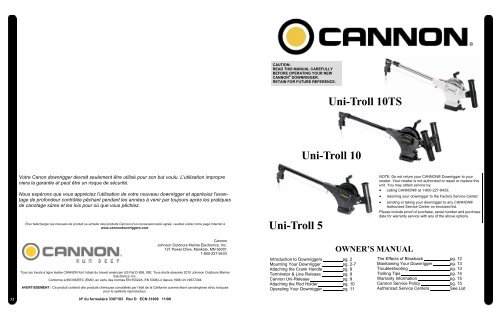
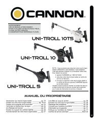
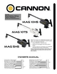
CAUTION:READ THIS MANUAL CAREFULLYBEFORE OPERATING YOUR NEWCANNON ® DOWNRIGGER.RETAIN FOR FUTURE REFERENCE.<strong>Uni</strong>-<strong>Troll</strong> <strong>10</strong>TS<strong>Uni</strong>-<strong>Troll</strong> <strong>10</strong>Votre Canon downrigger devrait seulement être utilisé pour son but voulu. L'utilisation impropreniera la garantie et peut être un risque de sécurité.Nous espérons que vous appréciez l'utilisation de votre nouveau downrigger et appréciez l'avantagede profondeur contrôlée pêchant pendant les années à venir par toujours après les pratiquesde canotage sûres et les lois pour où que vous pêchiez.Pour télécharger les manuels de produit ou acheter des produits <strong>Cannon</strong> d’un concessionnaire agréé, veuillez visiter notre page Internet àwww.cannondownriggers.com.<strong>Uni</strong>-<strong>Troll</strong> 5NOTE: Do not return your CANNON® Downrigger to yourretailer. Your retailer is not authorized to repair or replace thisunit. You may obtain service by:• calling CANNON® at 1-800-227-6433;• returning your downrigger to the Factory Service Center;• sending or taking your downrigger to any CANNON®Authorized Service Center on enclosed list.Please include proof of purchase, serial number and purchasedate for warranty service with any of the above options.<strong>Cannon</strong>Johnson Outdoors Marine Electronics, Inc.121 Power Drive, Mankato, MN 560011-800-227-6433Tous les treuils à ligne lestée CANNON font l’objet du brevet américain US Pat.D-269, 992. Tous droits réservés 20<strong>10</strong> Johnson Outdoors MarineElectronics, Inc.Conforme à 89/336/EEC (EMC) en vertu des normes EN 55022A, EN 50082-2 depuis 1996 LN V9677264AVERTISSEMENT : Ce produit contient des produits chimiques considérés par l’état de la Californie comme étant cancérigènes et/ou toxiquespour le système reproducteur.Introduction to <strong>Downriggers</strong> pg. 2Mounting Your Downrigger pg. 2-7Attaching the Crank Handle pg. 8Terminator & Line Release pg. 9<strong>Cannon</strong> <strong>Uni</strong>-Release pg. 9Attaching the Rod Holder pg. <strong>10</strong>Operating Your Downrigger pg. 11OWNER’S MANUALThe Effects of Blowback pg. 12Maintaining Your Downrigger pg. 13Troubleshooting pg. 13<strong>Troll</strong>ing Tips pg. 14Warranty Information pg. 15<strong>Cannon</strong> Service Policy pg. 15Authorized Service Centers See List32Nº du formulaire 3397<strong>10</strong>3 Rev D ECN 31809 11/09
Introduction to downriggersIntroduction to Controlled Depth FishingUndoubtedly there are many fishermenfamiliar with the methods and use of controlleddepth fishing. During the mid 1960's the state ofMichigan introduced Pacific salmon into the Greatlakes in an attempt to revitalize its sport fishingindustry. From this successful transplant, newfishing techniques and equipment weredeveloped. One such method was controlleddepth fishing which enabled fishermen to place alure at a desired depth by utilizing downriggers.Because of the varying factors (watertemperature, thermocline, weather, tides, time ofday, or time of year) it is necessary for successfulfishing to maintain specific water depths thatcoincide with fish movements and feedingpatterns.One essential feature of the downrigger isthe depth meter or gauge that indicates luredepth. This allows the angler to control as wellas return to specific depths where fish havebeen caught.Due to the success of controlled depthfishing, downriggers are now being usedthroughout the world to catch a wide variety ofspecies in both fresh and salt water. Whetherfishing for blues off Rhode Island, walleyes inLake Erie, sailfish off the coast of Florida, orstripers in Tennessee, the use of downriggerswill make your fishing more successful and moreenjoyable.GARANTIE LIMITÉE CANNON®Johnson Outdoors Marine Electronics, Inc. garantit à l’acheteurd’origine que si le produit en question (voir les exclusions ci-dessous)présente un défaut de fabrication ou de main-d’œuvre durant lespériodes de garantie suivantes, Johnson Outdoors MarineElectronics, Inc. décidera de réparer ou de remplacer sans frais(aucun remboursement en argent ne sera effectué) :1) Le bras, le moteur, les moulinets et toutes les pièces enLexan®*, incluant, sans s’y restreindre, les cadres et lesbases pour qu’ils soient exempts de tout défaut defabrication et de main-d’œuvre lorsqu’ils sont exposés à uneusure normale, pour la durée de vie de l’acheteur d’origine.2) Tous les autres composants auront une garantie limitée d’unan à partir de la date d’achat au détail d’origine, àl’exception des ARTICLES SUIVANTS QUI NECOMPORTENT AUCUNE GARANTIE : couvre-bottes,vêtements, ligne en Dacron, élastiques, goupille de sécuritépivotante, poids et câble métallique.Cette garantie limitée peut être appliquée seulement parl’acheteur d’origine; tous les acheteurs subséquentsacquièrent le produit « tel quel » sans garantie limitée. Laréparation ou le remplacement du produit tel qu’indiquédans cette garantie limitée constitue le recours unique etexclusif de l’acheteur d’origine et la responsabilité unique etexclusive de Johnson Outdoors Marine Electronics, Inc. encas de rupture de cette garantie.EXCLUSIONSCette garantie ne s’applique pas dans les circonstances suivantes :• Lorsque le produit a été connecté, installé, combiné, altéré,réglé, entretenu, réparé ou manipulé d’une manière quidiffère des instructions fournies avec le produit• Lorsque tout défaut, problème, perte ou dommage estsurvenu à la suite d’un accident, d’un abus, de négligence, oud’usage anormal ou de tout défaut de fournir un entretienraisonnable et nécessaire conformément aux instructionsdans le manuel du propriétairePOLITIQUE SUR L’ENTRETIEN DECANNON ®APRÈS L’EXPIRATION DE LA PÉRIODE DE GARANTIEAPPLICABLEAprès l’expiration de la période de garantie applicable, ou si l’unedes exclusions ci-dessus s’applique, les produits <strong>Cannon</strong>® serontréparés et facturés pour les pièces et la main-d’œuvre. Toutes lesréparations du fabricant réalisées après l’expiration de la période degarantie applicable portent une garantie limitée de 90 jours sousréserve des exclusions et limitations énoncées ci-dessus.POUR FAIRE VALOIR LA GARANTIE OU POUROBTENIR DES RÉPARATIONS APRÈS L’EXPIRATION DE LAGARANTIEPour obtenir un entretien sous garantie aux États-<strong>Uni</strong>s, le treuilou le composant considéré comme étant défectueux et la preuved’achat d’origine (incluant la date d’achat) doivent être présentés àun centre de service autorisé <strong>Cannon</strong>® ou au centre de service dufabricant <strong>Cannon</strong>® à Mankato, MN. À l’exception de ce qui estindiqué ci-dessous, tous les frais encourus pour les appels deservice, le transport ou la livraison à destination ou en provenance duCentre de service autorisé <strong>Cannon</strong>® ou de l’usine <strong>Cannon</strong>®, la maind’œuvrepour lofer, enlever, réinstaller ou regréer les produits pour leservice sous garantie, ou tout autre article similaire sont laresponsabilité unique et exclusive de l’acheteur. Les treuils à lignelestée achetés à l’extérieur des États-<strong>Uni</strong>s (ou les composants deces treuils) doivent être retournés franco de port avec la preuved’achat (incluant la date d’achat et le numéro de série) à un centre deservice autorisé <strong>Cannon</strong>® dans le pays où l’achat a été effectué. Leservice sous garantie peut être offert en contactant un centre deservice autorisé <strong>Cannon</strong>® figurant sur la liste ci-jointe ou encontactant l’usine par téléphone au 1 800 227 6433 ou partélécopieur au 1 800 527 4464. Si les réparations requises sontcouvertes par la garantie, nous paierons les frais de retour à toutedestination situé à l’intérieur des États-<strong>Uni</strong>s.Garantie et olitique sur l’entretien de <strong>Cannon</strong>Parts DescriptionAttach Line Releaseto Rear Hook onWeight1. Reel This is used to spool the cable, available in lengths ranging from 150 to 400 feet.2. Boom This is used to extend the weight out from the body of the downrigger and has a pulley fixedto its end. Boom lengths range from 24 to 53 inches.3. Swivel Head This relays the cable at the end of the boom to lower the weight.4. Weight This is used to maintain the depth at which you want to fish. Sizes of weights range from 4 to20 lbs.5. Cable This connects to the weight. Cable material is 150 lb. test stainless steel cable.6. Depth Meter This determines how much cable you have run out, enabling you to choose your trollingdepth.7. Mounting Base This attaches to the boat, enabling you to place the downrigger where you choose.LIMITATION ET EXCLUSION DES GARANTIES TACITES ET DECERTAINS DOMMAGESIL N’EXISTE AUCUNE GARANTIE EXPRESSE À PART CESGARANTIES LIMITÉES. JOHNSON OUTDOORS MARINEELECTRONICS, INC. NIE TOUTE RESPONSABILITÉ POUR LESDOMMAGES ACCESSOIRES ET INDIRECTS ET EN AUCUN CAS,UNE GARANTIE TACITE (SAUF POUR LE BRAS, LE MOTEUR,LES MOULINETS ET TOUTES LES PIÈCES EN LEXAN®*),INCLUANT TOUTE GARANTIE TACITE DE QUALITÉMARCHANDE OU D’ADAPTABILITÉ À UN BUT EN PARTICULIER,SE PROLONGERA AU-DELÀ D’UN AN À PARTIR DE LA DATED’ACHAT (ET DANS LE CAS DES COUVRE-BOTTES,VÊTEMENTS, LIGNE EN DACRON, ÉLASTIQUES, GOUPILLE DESÉCURITÉ PIVOTANTE, POIDS ET CÂBLE MÉTALLIQUE,JOHNSON OUTDOORS MARINE ELECTRONICS, INC. NIETOUTES GARANTIES TACITES). CE DOCUMENT CONSTITUEL’ENTENTE ENTIÈRE CONCLUE ENTRE LES PARTIES EN CEQUI CONCERNE LE SUJET DES PRÉSENTES; AUCUNEEXONÉRATION NI AUCUNE MODIFICATION NE SERA VALIDE ÀMOINS QU’UNE COPIE ÉCRITE SOIT SIGNÉE PAR JOHNSONOUTDOORS MARINE ELECTRONICS, INC..Certains états n’autorisent pas les limitations sur la durée de lagarantie tacite ou sur l’exclusion ou les limitations des dommagesindirects, par conséquent les limitations ou les exclusions ci-dessuspeuvent ne pas s’appliquer dans votre cas. Cette garantie vousdonne des droits spécifiques reconnus par la loi et possiblementd’autres droits selon l’état.* Lexan est une marque déposée de General Electric.VOUS NE DEVEZ PAS retourner votre treuil <strong>Cannon</strong> ® ou sescomposants à votre détaillant. Votre détaillant n’est pas autorisé àréparer ou à remplacer ces composants.Les composants principaux comme le moteur et le cadre principaldoivent être retournés à Johnson Outdoors Marine Electronics, Inc. àMankato, Minnesota, ou à un centre de service autorisé <strong>Cannon</strong> ® ,pour la réparation ou le remplacement. Pour réduire les coûtsd’expédition, nous vous suggérons d’enlever les pièces amoviblescomme le bras et les supports de cannes à pêche. Les petites piècesqui s’enlèvent facilement comme la poignée et/ou le compteurpeuvent être détachées du treuil et envoyées pour leur réparation ouremplacement.Conservez votre reçu ! Une preuve d’achat doit accompagnertout produit retourné.Adresse de retour :POUR VOTRE INFORMATION :<strong>Cannon</strong>121 Power DriveMankato, MN 56001Nº de sérieDate d’achatDétaillant28. Rod Holder This holds your fishing rods while trolling and may also be used for storing rods.CONSERVEZ CETTE SECTION DANS VOS REGISTRES31
Conseils pour la pêche à la traîne30Conseils pour la pêche à la traîne1) Testez vos leurres sur le côté du bateau avant deles diriger vers le bas et l’arrière. Cela vous permettrade vous assurer que le leurre s’agite et vacillecorrectement sans se renverser ni s’égarer. Certainsleurres peuvent être réglés avec précision pour créer unmouvement maximal. Par exemple, une légère courburede la queue d’une cuiller ou une torsion de l’hameçonsur le nez d’un bouchon peuvent affecter grandement laperformance du leurre.Aussi, si vous utilisez deux leurres ou plus, vousdevez vous assurer qu’elles sont compatibles. Lesleurres qui ne pas compatibles peuvent s’entremêler etcauser une perte de temps à les démêler. Vous devezles tester en premier pour éviter ce problème.2) Considérez différentes tailles, formes et couleursde leurres. Personne n’a réussi à trouver la raisonprécise qui incite le poisson à mordre à l’hameçon. Il n’ya aucun doute que des leurres de couleur, forme,mouvement et taille assortis aux fourrages (vairons,écrevisses, etc.) peuvent aider à inciter le poisson àmordre. Par contre, si les poissons comme un crapetarlequin, un achigan à petite bouche ou un saumonCoho protègent des zones de reproduction, ils peuventattaquer tout ce qui constitue une menace. Ainsi, desleurres de couleurs vives peuvent avoir plus de succèsque des leurres de couleurs ternes.3) Variez les vitesses de la pêche à la traîne. Sivous augmentez ou réduisez la vitesse du moteuroccasionnellement, vous changerez le mouvement desleurres et vous courrez la chance d’attirer des poissons.4) Variez les parcours de la pêche à la traîne et leslongueurs du plomb. La longueur de la lignedétermine comment le leurre se comportera et, danscertains cas, le mouvement qu’il créera. Pour débuter,placez des leurres à environ trois mètres (<strong>10</strong> pi) derrièreles poids du treuil à ligne lestée. Pour la pêche à latraîne avec une ligne plate, placez les leurres à environ15 m (50 pi) derrière le bateau et ensuite faites deschangements selon la réaction des poissons.Les parcours de la pêche à la traîne ont aussi unimpact sur le mouvement des leurres, c’est pourquoicertains pêcheurs à la ligne suivent un grand parcoursen S. Pendant les virages, la vitesse des leurresextérieurs augmentera momentanément alors que lesleurres intérieurs s’immobiliseront pendant un moment.Les poissons peuvent être attirés par des leurres quichangent de vitesses. Aussi, des parcours en dents descie permettent de couvrir une plus grande surface etgardent les leurres à l’extérieur du bouillonnement del’hélice, une considération importante pour les espècesbrunes et les autres espèces prudentes.5) Situez le poisson sur un plan vertical. Placez lesleurres à des endroits où des poissons peuvent setrouver. Les pêcheurs compétents appellent cesendroits des « zones de prise ». Elles comprennent lesrebords des lits, les structures le long du fond, lesdénivellations, les zones de températures préférées desespèces cibles et la thermocline.Rappelez-vous que les poissons se trouvent danscertaines zones pour certaines raisons (sources denourriture, endroit de protection, températurespréférées, etc.).6) Considérez des nœuds et émerillons spéciaux.Un bon émerillon à billes n’éliminera pas la torsion de laligne mais aidera à obtenir une performance maximaledu leurre. Plusieurs pêcheurs à la ligne ajoutent depetits émerillons aux anneaux brisés se trouvant déjàsur le leurre. Par contre, un émerillon peut réduire lemouvement d’un leurre sensible comme un Rapala.Certains pêcheurs attachent de petits anneauxaméliorés ou font des nœuds en boucle. Les nœuds enboucle en particulier peuvent améliorer les mouvementsverticaux et horizontaux des leurres. Tout bon manuelde pêche explique comment faire ces nœuds et d’autresnœuds.7) Considérez un déclencheur pour la pêche à latraîne avec une ligne plate. Un bon conseil est de fixerune section de câble de treuil ou de monofilamentrenforci au crochet ou à la poignée du ski situé sous letableau de la plupart des bateaux. À l’autre extrémité dumonofilament ou du câble, ajoutez une pince àdéclenchement. Après avoir placé le leurre à la distancevoulue, placez la canne dans son support, courbezensuite le bout et fixez la ligne dans le déclencheur.8) Ajoutez un protecteur contre les plantesaquatiques. Avez-vous des problèmes avec les plantesaquatiques qui s’accrochent sur les leurres ? Pensez àattacher une section de monofilament de 8 cm (3 po) àune distance de 0,3 m (1 pi) au-dessus du leurre. Lesfeuilles, petits végétaux et autres débris peuvent s’yaccrocher momentanément et ensuite tomber sur lecôté du leurre sans se mêler. Les leurres à l’épreuvedes végétaux sont aussi une autre bonne solution. Lescâbles de treuil sont des capteurs de végétaux efficacespour la pêche à la traîne du brochet, du maskinongé oude l’achigan dans les lacs infestés de végétaux.9) Ajoutez un hameçon à pointe. Lorsque le poissonmord presque et frappe les leurres sans s’accrocher,l’ajout d’un hameçon à pointe peut régler le problème. Ilsuffit d’attacher un hameçon triple à l’une desextrémités de la section de monofilament de <strong>10</strong> cm(4 po) et ensuite d’attacher l’hameçon supplémentairesur le dernier ensemble d’hameçons sur votre leurre.L’hameçon à pointe qui tire le leurre procure uneassurance supplémentaire.<strong>10</strong>) Gardez les hameçons affûtés. Parmi les meilleurspêcheurs, certains affûtent tous leurs hameçons aprèschaque prise. Les hameçons deviennent émoussés àcause de l’usage et de l’abus et probablement que plusde poissons sont perdus à cause des pointesémoussées que toute autre raison.Downrigger Mounting on BoatsA downrigger should be mounted where ever itis easy to operate and observe. You want to beable to see your fishing rod and to react quickly.So, choosing a good spot to mount yourdownrigger on your boat is 99% of the job.Due to the great variety of boats available,mounting your downrigger can be a dilemma.Having proper mounting accessories is essential.<strong>Cannon</strong> has a complete line of mountingaccessories to conveniently mount yourdownriggers on any boat.Mounting AccessoriesDeck Plates are necessary when extrastrength must be added to the base material ofthe boat and for attaching the downrigger to othermounting accessories.Gimbal Mounts are designed to fit mediumsizedflush mounted rod holders built into thegunwale of many larger fishing boats andcruisers. Only sturdy, high quality rod holdersshould be used for this temporary mountingsystem. Gimbal mounts are available in 9” or 12”post lengths.Clamp Mounts can be mounted at thejunction of two rail sections with the aid of two ¼"pieces of plywood. They will protect your rail fromany marks from the clamp and provide a non-slipsurface.ArrowsIndicateMountingLocationsDeck PlateClamp MountGimbal MountMOUNTING & SETUP3
MOUNTING & SETUPSide Rail MountingSide/Rail mounts can be mounted to awelded T-section. It can also be used at the tworail section butt joint. In both installations it isrecommended to use a non-slip material, suchas rubber or a thin wood sheet, between metalsurfaces.You can also use these for mounting to a verynarrow side gunwale. There is a plate providedfor back-up with bolts and washers. If thegunwale compartment is foamed in, thenwellnuts should be used. It is also recommendedto install two additional flat head screws throughthe top plate for stabilization (you will need todrill and countersink).Side/Rail on T-SectionSide/Rail on GunwaleRéglage du profondimètreLe profondimètre <strong>Cannon</strong> offre une mesure exacteet une fonction de réinitialisation facile. Pour leréinitialiser, vous n’avez qu’à glisser l’appareil loin dumoulinet jusqu’à ce que les engrenages soientdéclenchés. Faites tourner l’engrenage de l’appareilpour changer le réglage.NOTA : La profondeur de pêche réelle peut varierde la profondeur indiquée sur l’afficheur en raisonde la vitesse de la pêche à la traîne et du poids duboulet. (voir « Coup en arrière »)Entretien de votre treuil à lignelestéeAu début de chaque saison de pêche et plussouvent durant les périodes d'utilisation intensive,graissez légèrement le palier de butée, le relèvementde l'arbre du moulinet, la poulie à tête pivotante, laface du frein de rochet et le tourniquet du rochet.Dans le cas d'une utilisation en eau de mer, rincezcomplètement le treuil à l'eau fraîche après chaquevoyage et lubrifiez régulièrement. Remplacez le câbletous les deux ans au moins.Entretien et dépistage des problèmesDépistages de problèmesNOTE: In no case should this mount be usedon fiberglass ¼" thick or less unless it isfoamed in.Pedestal MountingPedestals are used wherever additional height isneeded for ease of operation or to clearobstructions, such as handrails.Caution: When using a pedestal mount or side/rail mount, do not extend thetelescopic boom on your <strong>Uni</strong>-<strong>Troll</strong>.The increased leverage will causeexcessive strain and possible failureof the mount.Pedestal for Additional HeightPROBLÈME :L’embrayage glisseSOLUTION :La vis de blocage sur le moulinet peut s’êtredesserrée sur l’arbre. Vous devez suivre lesinstructions ci-dessous :1) Déroulez le câble du moulinet.2) Enlevez la vis de blocage.3) Alignez le trou de la vis de blocage sur le moulinetavec le trou sur l’arbre du moulinet en insérant unetige de 3/16 po ou moins et tournez le moulinetjusqu’à ce que vous la sentiez tomber dans le troude l’arbre.4) Remplacez la vis de blocage et serrez-la jusqu’àce que vous ressentiez une résistance.5) En basculant légèrement le moulinet de l’arrièrevers l’avant tout en serrant la vis de blocage, vouspouvez la sentir s’enclencher dans le trou del’arbre. Le téton court sur la vis de blocage doitentrer dans le trou de l’arbre et ne doit passeulement être serré contre l’arbre du moulinet.429
Les effets du coup en arrièreCoup en arrièreEn quelques mots, le coup en arrière est ce quiarrive au poids du treuil lorsque vous le tirez dans l’eauderrière votre bateau. Plus votre vitesse augmente,plus la distance horizontale entre le poids et votre treuilaugmente. Plus vous allez vite, plus le poids s’éloignederrière vous. Plus le poids s’éloigne derrière vous,plus le poids se rapproche de la surface de l’eau.Le tableau suivant contient de l’information sur lecoup en arrière pour trois dimensions de poids de treuil<strong>Cannon</strong> qui sont tirés à trois vitesses différentes sansleurre et sans courant. La traînée du courant, la salinitéde l’eau et l’utilisation de produits non fabriqués par<strong>Cannon</strong> affecteront votre profondeur la de pêche à latraîne réelle.Par exemple, le premier tableau montre que si vouspêchez à la traîne à une vitesse de 6 km/h (4 mi/h)avec un poids de 4 kg (8 lb), et un câble de 30 m(<strong>10</strong>0 pi) dans l’eau sans courant; la boule du treuil setrouve en fait à une profondeur de 24 m (80 pi) environ.Profondeur du poids réelle (pieds)Tableaux concernant le coup arrière8 livres Poids à 2, 4 et 6 mi/h2 mi/h4 mi/h6 mi/hLongueur du câble immergé (pieds)<strong>10</strong> livres Poids à 2, 4 et 6 mi/hInstalling the Base on Your BoatDecks up to 7/16" thickWhere access to the underside of the deck isnot available, the mounting base can be mountedusing wellnuts. Use the base as a template to marklocations and drill four 1/2" holes. Mount the baseusing four 1/4"-20 x 1 1/2" truss head screws andfour wellnuts. Tighten the screws so the wellnuts arefirmly compressed as pictured.Decks thicker than 7/16"For decks thicker than 7/16", or where theunderside of the deck is accessible, mount the basewith screws, nuts, and washers. Use the base as atemplate to mark the locations and drill four 9/32"holes. Use four 1/4" -20 x 2 1/2" truss head screwsand four each flat washers, lock washers, and nuts.Fasten the base to the deck as pictured.NOTE: Wellnuts cannot be used on decks thickerthan 7/16".Outboard FacingSideorGunwaleDecksup to7/16"ThickNote LockingSlots in BaseBaseRearorSternStern FacingMOUNTING & SETUP2 mi/hProfondeur du poids réelle (pieds)4 mi/h6 mi/hLongueur du câble immergé (pieds)WellnutsBaseDecks Thicker Than 7/16"Washer, Lock Washer,and 1/4-20 Hex NutProfondeur du poids réelle (pieds)12 livres Poids à 2, 4 et 6 mi/h2 mi/h4 mi/h6 mi/h28Longueur du câble immergé (pieds)5
MOUNTING & SETUPDecks thinner than 1/4"Use a <strong>Cannon</strong> Deck Plate to preventdeflection and add stability to decks thinner than1/4". Use the deck plate as a template to mark thehole locations.If access to the underside of the deck is notavailable, the deck plate can be mounted usingscrews and wellnuts. Drill 1/2" holes. Use four1/4”-20 x 2" flat head screws and four wellnuts tomount deck plate as pictured. Tighten the screwsso the wellnuts are firmly compressed.Where the underside is accessible, mount thedeck plate using screws, nuts, and washers. Drill9/32" holes. Use four 1/4”-20 x 2" flat headscrews, nuts and washers (flat and lock). Fastenplate to deck as pictured. To secure the low-profilebase to the deckplate use four 1/4”-20 x 1 1/2"truss head screws.<strong>Cannon</strong> Deck PlateFonctionnement de votre treuil àligne lestéeAprès avoir installé le treuil à ligne lestée <strong>Cannon</strong>sur votre bateau, relâchez une longueur de ligne devotre canne à pêche et enroulez-la pour que le leurrese trouve à distance de 1,5 à 30 m (5 à <strong>10</strong>0 pi) dubateau. Ceci s’appelle une retombée.Attachez la ligne à pêche fermement dans ledéclencheur de ligne. Abaissez le poids à laprofondeur voulue, tel qu'indiqué sur le profondimètre.Placez la canne à pêche dans le support et embobinezla section lâche pour que votre canne à pêcheprésente une légère courbure. Lorsqu’un poissonmordra à l’hameçon, la ligne se séparera dudéclencheur. Vous serez alors libre de manipuler votrecanne à pêche pour capturer le poisson.Pour baisserle poidsFonctionnement de votre treuil à ligne lestéeDeck Up to 7/16" ThickWellnutBaseDeck Thicker Than 7/16"Washers, Screws,& NutsNOTE: When using the telescopic boom, we strongly recommend the use of a deck plate on allboats to provide adequate stability for the downrigger.Descente du poidsVous pouvez abaisser le poids pour la pêche àtraîne à une vitesse régulière en tournant doucementla poignée dans le sens antihoraire (dans le sensopposé au bras). En fonction de la manière dont voustournez la manivelle, vous pouvez faire descendre lepoids de pêche à la traîne aussi rapidement oulentement que vous voulez. Tournez la poignée de lamanivelle dans le sens horaire (vers le bras) jusqu'àentendre un déclic pour arrêter le poids. Vous pouvezainsi décider de laisser le poids descendre rapidementou lentement à une profondeur de la pêche à la traîneprédéterminée. Avec plusieurs treuils, vous pouvezfaire descendre tous les poids lentement, un à la fois,et ensuite les arrêter chacun à leur tour.Pour lever lepoidsFOR <strong>Uni</strong>-<strong>Troll</strong> <strong>10</strong> and <strong>Uni</strong>-<strong>Troll</strong> <strong>10</strong> TS:The Low-Profile Swivel Base mounting followsthe same procedure as for the deck plate exceptthat four 1/4"-20 x 1 1/2" truss head screws areused to fasten the mounting base and fouradditional 1/4"-20 x 2 1/2" truss head screws fix theswivel base to the boat deck.Mounting the Downrigger on the BaseSlide the bottom of the frame over the lip of thebase, with the boom outboard or facing the stern.Move the frame over the base until the latch clicksinto place. If properly seated, the frame shouldcompletely cover the base.CAUTION: If not fully seated, your downrigger canbe dislodged from the base.Tip: Periodically check base to ensure integrity. Thebase should be replaced at least every 5 years.Low-Profile Swivel BaseRemontée du poidsTournez la poignée de la manivelle dans le senshoraire (vers le bras) aussi rapidement que vous lesouhaitez pour remonter le poids.Réglage de la tension d'embrayageL'embrayage fait partie du mécanisme de lamanivelle. Tournez la poignée de la manivelle dans lesens horaire pour augmenter la traînée, et dans lesens antihoraire pour la diminuer.Avertissement : Retirez le poids du treuil avant denaviguer ou de le transporter dans une remorque.NOTA : si votre moulinet continue de glisser même sivous serrez solidement le bouton de réglage du frein,reportez-vous à la section de Dépistage desproblèmes dans ce livret.6Latch27
Fixation du support de cannes à pêcheFixation du support de cannes àpêcheLe support de cannes à pêche à autoverrouillagecomprend un disque de verrouillage qui permetd’aligner le support de cannes à pêche à desintervalles de 15 degrés. Faites glisser le tube dusupport de cannes à pêche dans la bride à la positionvoulue à l’intérieur de la partie recommandée (voir cidessous).Vous devez vous assurer que les épaulements àangle sont dirigés vers le haut. Placez le disque deverrouillage dans l’encoche d’assemblage sur le cadre.Faites glisser les bras de la bride en place àl’endroit où la languette sur le disque s’insère dansl’encoche sur la bride. Faites glisser la rondelle enétoile entre le bras de la bride et le cadre. Placez larondelle plate sur le boulon. Insérez ensuite le boulonavec la rondelle à travers la bride, le disque, le cadreet la rondelle en étoile pour qu’il sorte de l’autre côtéde la bride. Serrez l’écrou pour fixer le support decannes à pêche. Repositionnez le support de cannesen desserrant l’écrou et en réglant l’inclinaison.AVERTISSEMENT : Ce support de cannes à pêcheest conçu pour des lignes d’essai de 14 kg (30 lb)maximum seulement et son usage n’est pasrecommandé avec des apparaux cotés IGFA deplus de 14 kg (30 lb). Une courroie de sécurité(non incluse) est recommandée pour toutes lesapplications.Le support de cannes à pêche n’est pas garantis’il est utilisé avec des apparaux de plus de 14 kg(30 lb). L’équipement placé dans les supports àcannes à pêche et leur perte est la responsabilitéde l’utilisateur et ne sont pas garantis parJOHNSON OUTDOORS MARINE ELECTRONICS,INC.. La fixation doit être conforme auxinstructions et au diagramme ci-dessus pour êtregarantie.Setting Up Your DownriggerAttaching the BoomTelescopic BoomThe intermediate section of the telescopicboom must be extended approximately 5" beforethe boom locking screw can engage the hole inthe boom. Slip the boom end into the frame andalign the holes. Secure with boom locking screw.To adjust boom length, with the boomextending away from you, rotate clampsapproximately 1/4 turn counter - clockwise tounlock, and slide boom section to desired position.To lock, rotate clamp clock-wise until tight.TIP: Whenever downriggers with boom lengthsbeyond 24" are used, <strong>Cannon</strong>'s Retro-EaseWeight Retriever will make bringing in the weightsafe and easy. It attaches to the cable below theboom end allowing you to pull the weight toyourself without having to lean way out or collapsethe boom to reach the weight.The 3/4"-Long PhillipsScrew Must EngageHole in BoomClampsMOUNTING & SETUPAssemblage support de canne à pêche simpleEmplacementrecommandé pourfixer le support decanne à pêchePlacement de larondelle en étoileAssemblage support de canne à pêche doubleThe Standard 24 Inch Boom inserts into thedownrigger frame (see bottom diagram on page7). Be sure that the boom is held securely byseating it firmly against the shoulder inside thefame and fastening the boom locking screw suchthat it engages the hole in the boom.Assemble Swivel Head To BoomInsert the telescopic boom-end into the boomalignholes and fasten in place with a #8 x 5/8screw. Spread the swivel head side plates and slipthe assembly over the boom end axle. Snap theassembly together and install two #4 x 1/2" screwsinto the swivel head.Standard 24"BoomÉpaulement àangleTIP: Adjusting the angle of the boom head canhelp control cable wrap on the reel.#8 x 5/8"Screw (1)#4 x 1/2"Screws (2)267
Attaching the crank handleAttaching the Crank HandleAssemblyMake sure the thrust bearing is sandwichedbetween its two races. The thrust bearing springshould be oriented where the narrow end istoward the bearing. Slide the bearing with racesand spring over the ratchet shaft. Then, carefullythread the crank handle onto the shaft andcontinue turning the handle clockwise until theclutch is fully tightenedNOTE: Place your fingertip on the edge of thebearing and races. This allows the crank to bethreaded more easily until the spring putsresistance on the clutch pad.ThrustBearingTerminer le câble du treuil à ligne lestéeCache en caoutchoucCâbleConseil: nous vous recommandons d'utiliserdes pinces coupe-fil pour procéder à cettepartie du montage.Déroulez environ 2 pi de câbleet faites-le passer dans le cacheen caoutchouc.ÉmerillonagrafeCONSEIL: Utilisez uniquement un câble droit, le câble ne doit pas être courbé.Faites passer lecâble dans le TROUA.Faites entrer six pode câble à l'intérieur.Faites passer lecâble à l'intérieur dela tête pivotante, puisdans la partieinférieure duterminator.Faites sortir le câblepar le TROU B etfaites-le passer dansle TROU C. Poussezle câble jusqu'à ceque son extrémitéentre en contact avecl'intérieur du crochetdu terminator.TROU ATendez lecâble enappuyant surle terminatorjusqu'à ce qu'ilse ferme.Ensuite, tirezen haut et enbas pourtendre lecâble. Veillezà ce que lecâble passedans lecrochet.TêtepivotanteAttachez au terminator.Examinez la partie supérieure du terminator et notezl'ordre détaillé pour faire passer le câble.ENTRÉE CÂBLEENTRÉE CÂBLESORTIEGlissez le cache sur la partie supérieure duterminator et faites un test en tirant sur lecâble.Le câble servira à attacher un poids pour lapêche <strong>Cannon</strong>.Terminator et déclencheur de ligne et <strong>Uni</strong>-ReleaseSpring<strong>Uni</strong>-Release de <strong>Cannon</strong>Le <strong>Uni</strong>-Release de <strong>Cannon</strong> s’attache directementsur le poids du treuil à ligne lestée. Attachez la lignesur l’attache à l’extrémité du déclencheur et cliquezensuite pour régler la tension. Le déclencheur peut êtreutilisé avec n’importe quelle ligne en eau douce ou eneau de mer et peut être réglé à une tension de serragede 1 à <strong>10</strong> kg (2 à 22 lb) sur la ligne.FermerOuvrirRégler latensionLigne àpêcheRacesCrankHandlePour changer la tension de déclenchement de laligne, tournez le bouton de tension vers (+) pourl’augmenter ou vers (-) pour la réduire. La tension peutaussi varier selon l’emplacement de la ligne dans lespinces. La tension est plus élevée si la ligne est placéevers la charnière et la tension est plus basse si la ligneest placée plus près de l’ouverture. Pour ouvrir ledéclencheur, étalez les bras de déclenchement avec lepouce et l’index en appliquant une pression sur lescôtés.OuvrirPads825
Fixation de la poignée de la manivelleFixation de la poignée de lamanivelleAssurez-vous que le palier de butée est bienintercalé entre ses deux courses. Le ressort du palierde butée doit être tourné dans la même direction quel'extrémité étroite vers le palier. Glissez le palier avecles courses et le ressort par dessus l'arbre de rochet.Ensuite, faites passer avec précaution la poignée demanivelle sur l'arbre et tournez la poignée dans le senshoraire jusqu'à ce que l’embrayage soit complètementserré.NOTA : Placez votre doigt sur le bord du palier etdes courses. Cela permet d'enfiler la manivelleplus facilement jusqu'à ce que le ressort exerceune tension sur le patin d'embrayage.Terminating the Downrigger CableRubber CushionCableTip: A set of pliers with wire cutters isrecommended for this part of setup.Unwind about 2 feet of cableand thread the cable throughthe rubber cushion.Attach to terminator.Snap &SwivelExamine the top of the terminator and note theorder shown in the detail to run cable.CABLE INCABLE INCABLEOUTTERMINATOR & LINE RELEASELead cable intoHOLE A.Pull six inches ofcable through.Thread cablethrough swivel,then up intobottom of theterminator.Lead cable out ofHOLE B and intoHOLE C. Pushthe cable until itsend touches theinside of theterminator hook.TIP: Use only straight cable, not kinked.HOLE ATighten cableby squeezingterminator untilit snaps shut.Then pull at topand bottomuntil drawntight. Makesure that thecable threadsin groove ofthe hook.SwivelSlide the cushion over the top of theterminator and give it a test pull.The cable is set to attach a <strong>Cannon</strong><strong>Troll</strong>ing Weight.Palier debutéeRessort<strong>Cannon</strong> <strong>Uni</strong>-ReleaseThe <strong>Cannon</strong> <strong>Uni</strong>-Release attaches directly tothe downrigger weight. Attach fishing line to theclip at the end of the release, and then clickthrough a series of increasing tension settings.The release can be used with any test line on saltor fresh water and may be adjusted from 2 to 22pounds of grip tension on the line.CloseOpenTensionAdjustFishing LineCoursesPoignée de lamanivelleTo change line release tension, turn tension knobto (+) to increase or (-) to decrease. Tension alsomay vary according to where the line is placed inthe grips. Higher tension is on the line if it is setback toward the hinge, and lower if set closer tothe opening. To open the release, spread therelease arms with thumb and forefinger applyingpressure to the sides.OpenGripperPads249
ATTACHING THE ROD HOLDERAttaching the Rod HolderThe positive lock rod holder incorporates alocking disk that allows the rod holder to bealigned in 15 degree increments. Slide the rodholder tube into the clamp to the desired positionwithin the recommended area (see below).Be sure the angled shoulders are facing up.Place the locking disk into the mating recess ofthe frame.Slip the clamp arms in place where theobround tab on the disk fits into the slot on theclamp. Slide the star washer between the arm ofthe clamp and the frame. Place the flat washeronto the bolt. Then insert the bolt with washerthrough the clamp by entering the disk, goingthrough the frame, the star washer, and out theother side of the clamp. Tighten the nut to securethe rod holder. Reposition the rod holder byloosening the nut and adjusting the tilt.CAUTION: This rod holder is intended for useof up to 30 lb. test line only, and is notrecommended for use with any tackle IGFArated higher than 30 lb. A safety strap (notincluded) is recommended for allapplications.The rod holder assembly is not warrantedwhen used with tackle above 30 lbs.Equipment placed in the rod holders and theloss thereof is the responsibility of the userand is in no way warranted by JOHNSONOUTDOORS MARINE ELECTRONICS, INC..Mounting must be in accordance with theabove instructions and diagram to bewarranted.Mise en place du treuil à ligne lestéeFixation du brasBras télescopiqueLa partie intermédiaire du bras télescopique doitêtre allongée d’environ 13 cm (5 po) avant que la vis deblocage du bras puisse entrer dans le trou sur le bras.Faites glisser l’extrémité du bras dans le cadre etalignez les trous. Fixez à l’aide des vis de blocage dubras.Pour régler la longueur du bras, placez le bras loinde vous, faites tourner les brides d’environ 1/4 de tourdans le sens antihoraire pour les déverrouiller et faitesglisser la partie du bras à la position voulue. Pourverrouiller, faites tourner la bride dans le sens horairejusqu’à ce qu’elle soit serrée.CONSEIL : Si un treuil à ligne lestée avec un bras deplus de 61 cm (24 po) de long est utilisé, un dispositifde rappel de poids Retro-Ease de <strong>Cannon</strong> aidera àramener le poids de manière plus facile et sécuritaire. Ils’attache au câble situé sous l’extrémité du bras pourvous permettre de tirer le poids vers vous sans avoir àvous pencher excessivement vers l’avant ou à plier lebras pour atteindre le poids.La vis Phillips de¾ po doit être inséréedans le trou du brasBridesFixation de votre treuil à ligne lestéeSingle Rod Holder AssemblyDual Rod Holder AssemblyLe bras standard de 61 cm (24 po) s’insère dans lecadre du treuil à ligne lestée. Vous devez vous assurerque le bras soit maintenu solidement en l’appuyantfermement contre l’épaulement à l’intérieur du cadre eten serrant la vis de blocage du bras de manière à cequ’elle entre dans le trou sur le bras.Bras standardde 24 poRecommendedArea to ClampRod HolderStar WasherPlacementAssemblage de la tête pivotante sur le brasInsérez l’extrémité du bras télescopique dans lestrous d’alignement sur le bras et fixez avec une vis de#8 x 5/8 po. Étalez les plaques latérales de la têtepivotante et faites glisser l’assemblage par dessus l’axed’extrémité du bras. Enclenchez l'assemblage etinstallez deux vis de #4 x 1/2 po dans la tête pivotante.CONSEIL : Le réglage de l’angle de la tête du braspeut aider à contrôler l’enroulement du câble sur lemoulinet.AngledShoulderVis #8x5/8 po(1)Vis #4x1/2 po(2)<strong>10</strong>23
Fixation de votre treuil à ligne lestéePonts d’une épaisseur inférieure à 1/4 poUtilisez une plaque de pont <strong>Cannon</strong> pourprévenir la courbure et procurer plus de stabilitéaux quais d’une épaisseur inférieure à 1/4 po.Utilisez une plaque de pont comme gabarit pourmarquer l’emplacement des trous.Si l’accès à la sous-face du pont n’est paspossible, la plaque de pont peut être installée àl’aide de vis et d’écrous-douilles. Percez des trousde 1/2 po. Utilisez quatre vis à tête fraisée de 1/4-20 x 2 po et quatre écrous-douilles pour installerla plaque de pont, tel que montré. Serrez les vispour que les écrous-douilles soient compriméssolidement.Si la sous-face est accessible, la plaque depont peut être fixée à l’aide de vis, d’écrous et derondelles. Percez des trous de 9/32 po. Utilisez unensemble de fixation de la plaque de pont <strong>Cannon</strong>comprenant quatre vis à tête fraisée 1/4-20 x 2 po,des écrous et des rondelles (plates et de frein).Operating Your DownriggerAfter mounting the <strong>Cannon</strong> downrigger to yourboat, release some line from your rod and reel sothat the lure is anywhere from 5 to <strong>10</strong>0 feet behindthe boat. This is called drop back.Attach the fishing line firmly into the linerelease. Lower the weight to the desired depth asindicated on the depth meter. Place the fishing rodin the rod holder and reel up the slack so that yourrod has a slight bend in it. When a fish strikes thelure, the line will separate from the release. Thenyou will be free to fight the fish and bring it in onyour rod and reel.To LowerWeightOPERATING YOUR DOWNRIGGERPont jusqu’à 7/16 po d’épaisseurÉcrou-douilleBaseFixez la plaque au pont, tel que montré. Pour attacher solidement la base à la plaque de pont, utilisez quatre vis àtête bombée large de 1/4-20 x 2 po.NOTA : Si vous utilisez un bras télescopique, nousvous recommandons fortement d’utiliser une plaquede pont sur tous les bateaux pour stabiliser le treuil àligne lestée adéquatement.Pour les modèles <strong>Uni</strong>-<strong>Troll</strong> <strong>10</strong> et <strong>Uni</strong>-<strong>Troll</strong> <strong>10</strong> TS :La procédure de fixation de la base pivotante à profilbas est la même que celle de la plaque de pont, sauf quequatre vis à tête bombée large de 1/4 po-20 x 2 1/2 posont utilisées pour fixer la base et quatre vis à têtebombée large supplémentaires de 1/4 po-20 x 2 1/2 poservent à fixer la base pivotante au pont du bateau.Fixation du treuil sur la baseFaites glisser la partie inférieure du cadre par dessusle rebord de la base, avec le bras dirigé vers l’extérieur ouen face de la poupe. Déplacez le cadre sur la base jusqu'àce que le vérin s'enclenche avec un déclic. Lorsqu'il estplacé correctement, le cadre doit recouvrir complètementla base.AVERTISSEMENT : si le cadre n'est pas placécorrectement, votre treuil peut se déloger de la base.Base pivotante à profil basPlaque de pontPont d’une épaisseur supérieure à 7/16 poRondelles, rondelles deblocage, vis et écrousLowering the WeightYou can lower the trolling weight at a controlledrate by turning the crank handle gently counterclockwise(away from the boom). Depending onhow far you turn, you can let your trolling weightdescend as fast or as slowly as you wish. Turn thecrank handle clockwise (toward the boom) until ityou hear a click to stop the weight. This gives youcontrol to let it plunge rapidly or sink slowly to apredetermined trolling depth. With multipledownriggers, you could start all your weightscreeping down, one at a time, and then stop themeach in turn.Raising the WeightTurn the crank handle clockwise (toward theboom) as rapidly as you desire to retrieve thetrolling weight.Adjusting the Clutch TensionThe clutch is built into the crank mechanism.Turn crank handle clockwise to increase the dragand counterclockwise to reduce it.NOTE: In case your reel continues to slip nomatter how hard you tighten the crank see theTroubleshooting section of this booklet.CAUTION: Remove weight from downriggerbefore traveling either by water or transporting ontrailer.To RaiseWeight22Conseil : Vérifiez périodiquement l’intégrité de la base.La base doit être remplacée au moins à tous les 5 ans.Vérind'accrochage11
BlowbackBlowbackSimply stated, blowback is what happens tothe downrigger weight when you pull it through thewater behind your boat. As your speed increases,so does the horizontal distance between theweight and your downrigger. The faster you go,the farther the weight is behind you. The fartherthe weight is behind you, the shallower the weightis.The following charts provide you withblowback information for three sizes of <strong>Cannon</strong>downrigger weights pulled at three differentspeeds with no lures attached and with no current.Current drag, water salinity and the use of non-<strong>Cannon</strong> products will affect your actual trollingdepth.As an example, the first chart shows that if youare trolling at 4 MPH with an 8 pound weight andyou have <strong>10</strong>0 FT. of cable in the water with nocurrent; the downrigger ball is actually at a depthof about 80 FT.Actual Depth of Weight (ft.)Blowback Charts8-Lb. Weight at 2, 4, and 6 MPHAmount of Cable in Water (ft.)<strong>10</strong>-Lb. Weight at 2, 4, and 6 MPH2 MPH4 MPH6 MPH2 MPHInstallation de la base sur votrebateauPonts jusqu’à 7/16 po d’épaisseurSi l’accès à la sous-face du pont n’est pas possible,la base peut être installée à l’aide d’écrous-douilles.Utilisez la base comme gabarit pour marquerl’emplacement et percez quatre trous de 1/2 po. Fixez labase à l’aide de quatre vis à tête bombée large de 1/4-20x 4 po et de quatre écrous-douilles. Serrez les vis pourque les écrous-douilles soient comprimés solidement, telque montré.Ponts d’une épaisseur supérieure à 7/16 poPour les ponts d’une épaisseur supérieure à 7/16 po,ou dont l’accès à la sous-face est accessible, fixez labase avec les vis, écrous et rondelles. Utilisez la basecomme gabarit pour marquer l’emplacement et percezquatre trous de 9/32 po. Utilisez quatre vis à tête bombéelarge de 1/4-20 x 4 po et quatre rondelles plates, quatrerondelles de frein et quatre écrous. Serrez la base sur lepont, tel que montré. NOTA : Les écrous-douilles nepeuvent pas être utilisés sur des ponts d’une épaisseursupérieure à 7/16 po.Vers l'extérieurPartielatéraleou platbordFentes deblocage dansla baseVers la poupeArrièreoupoupePonts jusqu’à 7/16 po d’épaisseurBaseFixation de votre treuil à ligne lestéeActualDepth of Weight (ft.)4 MPH6 MPHÉcrous-douillesPonts d’une épaisseur supérieure à 7/16 poBaseAmount of Cable in Water (ft.)12-Lb. Weight at 2, 4, and 6 MPH2 MPHRondelle, rondelle deblocage et écrouhexagonal 1/4-20Actual Depth of Weight (ft.)4 MPH6 MPH12Amount of Cable in Water (ft.)21
Fixation de votre treuil à ligne lestéeFixation de la lisse latéraleLes supports de lisse latérale peuvent être fixéssur une section en T soudée. Ils peuvent aussi êtreutilisés sur le joint à franc bord de la section des deuxlisses. Pour ces deux types d’installation, il estrecommandé d’utiliser un matériel antidérapantcomme du caoutchouc ou un plaqué en bois minceentre les surfaces en métal.Vous pouvez aussi les utiliser pour la fixation surun plat-bord latéral très étroit. Une plaque d’appuiavec boulons et rondelles est fournie. Si lecompartiment du plat-bord est en mousse, vousdevrez utiliser des écrous-douilles. Il est aussirecommandé d’installer deux vis à tête fraiséesupplémentaires dans la plaque supérieure pour plusde stabilité (vous devrez percer et chasser).NOTA : Ce support ne doit pas en aucun cas êtrefixé sur une pièce en fibre de verre de ¼ pod’épaisseur ou moins, à moins qu’elle soitrecouverte de mousse.Lisse latérale sur une section en TLisse latérale sur un plat-bordAdjusting the Depth MeterThe <strong>Cannon</strong> Depth Meter provides non-slipaccuracy, plus easy resetting. To reset, just slidethe meter away from the reel until the gears aredisengaged. Spin meter gear to change setting.NOTE: Actual fishing depth may vary fromdepth shown on meter due to trolling speedand weight of cannon ball. (See "Blowback")Maintaining Your DownriggerAt the beginning of each fishing season andmore often during periods of heavy usage, lightlygrease the thrust bearing, reel shaft bearings,swivel head pulley, ratchet brake face, andratchet dog. When using for saltwater fishing,thoroughly rinse the entire downrigger with freshwater after each trip and lubricate on a frequentbasis. Replace the cable at least every two years.For repairs or servicing your downrigger referto the Warranty Information section of thisbooklet.maintaining & TROUBLE SHOOTINGTrouble ShootingFixation de socleLes socles sont utilisés lorsqu’une hauteursupplémentaire est requise pour faciliter lefonctionnement ou éviter les obstructions comme lesmains courantes.Avertissement: Si vous utilisez un support desocle et/ou un support de lisse, vous ne devezpas allonger le bras télescopique de votre Mag 20DT. L’effet de levier accru causera unecompression excessive et une défaillancepossible du support.Socle permettant une surélévationPROBLEM:Clutch slipsSOLUTION:The set screw in the reel may have comeloose off the shaft. Follow the instructionsbelow:1) Unwind the cable from the reel.2) Remove the set screw.3) Align the set screw hole in the reel with thehole in the reel shaft by inserting a 3/16" orsmaller rod and rotating the reel until you feelit drop into the shaft hole.4) Replace the set screw and tighten until youfeel resistance.5) By gently rocking the reel back and forth whiletightening the set screw, you can feel itengage in the shaft hole. The half dog pointon the set screw must enter the hole in theshaft; not just be tightened against the reelshaft.2013
TROLLING TIPSTen Good <strong>Troll</strong>ing Tips1) Test your lures over the boat side beforesending them down and back. Do this to makesure the lure wiggles and wobbles properly withoutgoing belly up or wandering off. Some lures can beadjusted, fine tuned actually, to impart maximumaction. For example, a slight bend in the tail of aspoon or twist of the hook eye in the nose of a plugcan make a noticeable difference in how the lureperforms.Also, when running two or more lures, make surethe offerings are compatible. Lures that run out ofharmony with each other are bound to tangle andthat means wasted time to straighten out the mess.Testing them first will avoid the problem.2) Consider different sizes, shapes, and colorsof lures. No one has ever figured out with precisionwhat makes a fish strike or snub a lure. There is nodoubt, that matching the forage (minnows, crayfish,etc.) in color, shape, action, and size can helptrigger those strikes from hungry fish. On the otherhand, if fish such as bluegills, small mouth bass orCoho salmon are protecting spawning beds, theymay attack whatever is threatening. So, brightcolors in lures may out produce bland colors.3) Vary trolling speeds. Goosing the engine nowand then or slowing to a crawl every so often willchange the action of the lures and may get fish tostrike them.4) Vary trolling patterns and lead lengths. Theamount of line you let out often determines howdeep the lure will run and, to some extent, whatdegree of action it will impart. For starters, considerrunning lures about ten feet behind downriggerweights. If flat line trolling, put them back about fiftyfeet, then experiment depending on what the fishdo.<strong>Troll</strong>ing patterns affect lure action too, that iswhy some anglers like to wheel a lazy S course.On turns, outside lures will speed up momentarilywhile inside lures hang for a moment or two. Fishmay nail lures that change speeds. Also, zigzagpatterns allow for more water coverage, plus itkeeps lures out of propeller boil, an importantconsideration for browns and other wary species.5) Locate fish on a vertical plane. Place lures inareas where fish might be. Skilled fishermen callthese areas the “strike zones”. They include theedges of the week beds, structure along bottom,drop-offs, preferred temperature of the targetspecies, and the thermocline. Remember that fishoccupy certain areas for certain reasons (sourcesof food, protective cover, preferred temperatures,etc.).6) Consider special knots and swivels. A goodball bearing swivel will all but eliminate line twistand will aid in getting maximum performance froma lure. Many anglers add the tiny swivels to splitrings already on the lure itself. On the other hand,a swivel may dampen the action of a sensitive lure,such as a Rapala. Some fisherman tie tinyimproved cinch or loop knots. Loop knots inparticular may enhance up and down and side toside action of lures. Any good fishing manual willexplain how to tie these and other knots.7) Consider releases for flatline trolling. Agood tip is to secure a piece of downrigger cable orheavy monofilament to the water ski hook orhandle below the transom of most boats. To theother end of the mono or cable, add a pinch-rrelease.After letting out your lure to the desiredistance, put the rod in its holder, then bend the tipand secure the fishing line in the release.8) Add a weed guard. Having trouble with weedshanging up lures? Consider tying a three-inchpiece of monofilament a foot above the lure.Leaves, smaller weeds and other debris may catchhere momentarily then fall off to the side of the lurewithout tangling. Weedless lures are another smartconsideration. Downrigger cables are effectiveweed catchers when trolling for pike, muskies, orbass in weed-infested lakes.9) Add a stinger hook. When fish short strike,slap at lures without becoming hooked, adding astinger hook can solve the problem. Simply tie atreble hook to one end of a four inch piece ofmonofilament and then tie the extra hook to thelast gang of hooks on your lure. The stinger hook,which trails the lure, provides extra insurance.<strong>10</strong>) Keep hooks sharp. Some of the bestfishermen sharpen all hooks after every fishcaught. Hooks get dull through both use andmisuse, and probably more fish are lost to dullpoints than anything else.Fixation du treuil à ligne lestée surles bateauxUn treuil à ligne lestée doit être fixé à un endroit oùil sera facile de l’utiliser et de l’observer. Vous voulezêtre capable d’observer votre canne à pêche et deréagir rapidement. Ainsi, le choix de l’emplacement devotre treuil à ligne lestée sur votre bateau compte pour99 % du travail.En raison de la grande variété de bateauxdisponibles, la fixation de votre treuil à ligne lestée peutcauser un dilemme. Il est essentiel d’avoir lesaccessoires de fixation appropriés. <strong>Cannon</strong> offre unegamme complète d’accessoires de fixation pour vousaider à fixer votre treuil à ligne lestée sur tous les typesde bateau.Accessoires de fixationLes pontets sont nécessaires pour ajouter unerobustesse supplémentaire au matériel de base dubateau et pour attacher le treuil à ligne lestée àd’autres accessoires de fixation.Les supports à cardan sont conçus pours’ajuster aux supports de cannes à pêche moyensencastrés dans le plat-bord de plusieurs bateaux depêche plus gros et de yachts à moteur. Seulement dessupports de cannes à pêche robustes et de qualitésupérieure doivent être utilisés avec ce système defixation temporaire. Les supports à cardan sontdisponibles avec des montants de 23 ou 40 cm (9 ou12 po) de long.Les supports de bride peuvent être installés à lajonction de deux sections de lisses à l’aide de deuxmorceaux de contreplaqué de ¼ po. Ils protégerontvotre lisse des marques de bride et procureront unesurface antidérapante.Les flèches indiquentl'emplacement pourl'installationPlaque de pontSupport à cardanSupport de brideFixation de votre treuil à ligne lestée1419
Introduction aux treuils à ligne lestéeIntroduction à la pêche en haute mercontrôléeSans aucun doute, il existe de nombreux pêcheursqui sont familiers avec les méthodes et les activités dela pêche en haute mer. Au milieu des années 60, l’étatdu Michigan a introduit le saumon du Pacifique dansles Grands Lacs afin de revitaliser l’industrie de lapêche de loisir. Dans la foulée de cette transplantationréussie, de nouvelles techniques et de nouveauxéquipements de pêche ont été mis au point. Une desnouvelles méthodes a été la pêche en haute mercontrôlée qui permet au pêcheur d’aller porter le leurreà la profondeur voulue à l’aide d’un treuil à ligne lestée.À cause de divers facteurs (température de l’eau,thermocline, climat, marée, heure du jour ou périodede l’année), il est nécessaire pour réussir à pêcher degarder le leurre à des profondeurs spécifiques quicoïncident avec les mouvements des poissons et leshabitudes d’alimentation.Description des piècesUne caractéristique importante du treuil à lignelestée est le profondimètre qui permet de mesurer laprofondeur du leurre. Il permet au pêcheur decontrôler la profondeur et de retourner à desprofondeurs spécifiques où des poissons ont ététrouvés précédemment.En raison du succès de la pêche en haute mercontrôlée, les treuils à ligne lestée sont maintenantutilisés dans le monde entier pour pêcher une grandevariété d’espèces en eau douce et en eau de mer.Que vous soyez à la pêche au tassergal près deRhode Island, au doré jaune sur le lac Érié, au voiliersur la côté de la Floride ou au bar rayé auTennessee, vous aurez plus de succès et de plaisir sivous utilisez un treuil à ligne lestée.1. Moulinet Il sert à embobiner le câble qui est offert en longueur allant de 46 à 122 m (150 à 400 pi).2. Bras Il sert à distancer le poids du treuil à ligne lestée et il comporte une poulie à son extrémité.Les longueurs des bras varient entre 61 et 135 cm (24 et 53 po).3. Tête pivotante Elle relais le câble à l’extrémité du bras afin d’abaisser le poids.Attachez le déclencheur deligne au crochet arrière surle poids4. Poids Il sert à maintenir la profondeur voulue pour la pêche. Les poids varient de 2 à 9 kg (4 à20 lb).5. Câble Il est relié au poids. Il s’agit d’un câble de contrôle en acier inoxydable de 60 kg (150 lb).6. Profondimètre Il indique la longueur de câble utilisée et il vous permet de choisir la profondeur voulue.CANNON® LIMITED WARRANTYJohnson Outdoors Marine Electronics, Inc. warrants to theoriginal purchaser that if the accompanying product (see exclusionsbelow) proves to be defective in material or workmanship within thefollowing warranty periods, Johnson Outdoors Marine Electronics,Inc. will, at its option, either repair or replace same without charge(but no cash refunds will be made):1) The boom, motor, and reels, plus all Lexan®* parts, includingbut not limited to frames and bases, will be free from defectsin materials and workmanship, subject to normal wear andtear, for the original purchaser's lifetime.2) All other items will have 1-year limited warranties from thedate of original retail purchase, except THE FOLLOWINGITEMS THAT HAVE NO WARRANTY WHATSOEVER: bootcovers, clothing, Dacron line, rubber bands, swivel lock pin,weights, and wire cable.This limited warranty may be enforced only by the originalpurchaser; all subsequent purchasers acquire the product "asis" without any benefit of this limited warranty. Repair orreplacement of the product as set forth in this limited warrantyshall be the original purchaser’s sole and exclusive remedyand Johnson Outdoors Marine Electronics, Inc.’s sole andexclusive liability for breach of this warranty.EXCLUSIONSThis warranty does not apply in the following circumstances:• When the product has been connected, installed, combined,altered, adjusted, serviced, repaired, or handled in a mannerother than according to the instructions furnished with theproduct• When any defect, problem, loss, or damage has resulted fromany accident, misuse, negligence, carelessness, or abnormaluse, or from any failure to provide reasonable and necessarymaintenance in accordance with the instructions of theowner's manualLIMITATION AND EXCLUSION OF IMPLIED WARRANTIES ANDCERTAIN DAMAGESTHERE ARE NO EXPRESS WARRANTIES OTHER THANTHESE LIMITED WARRANTIES. JOHNSON OUTDOORS MARINEELECTRONICS, INC.. DISCLAIMS LIABILITY FOR INCIDENTALAND CONSEQUENTIAL DAMAGES, AND IN NO EVENT SHALLANY IMPLIED WARRANTIES (EXCEPT ON THE BOOM, MOTOR,REELS, AND ALL LEXAN®* PARTS), INCLUDING ANY IMPLIEDWARRANTY OF MERCHANTABILITY OR FITNESS FORPARTICULAR PURPOSE, EXTEND BEYOND ONE YEAR FROMTHE DATE OF PURCHASE (AND IN THE CASE OF THE BOOTCOVERS, CLOTHING, DACRON LINE, RUBBER BANDS, SWIVELLOCK PIN, WEIGHTS, AND WIRE CABLE, JOHNSON OUTDOORSMARINE ELECTRONICS, INC. DISCLAIMS ALL IMPLIEDWARRANTIES). THIS WRITING CONSTITUTES THE ENTIREAGREEMENT OF THE PARTIES WITH RESPECT TO THESUBJECT MATTER HEREOF; NO WAIVER OR AMENDMENTSHALL BE VALID UNLESS IN WRITING SIGNED BY JOHNSONOUTDOORS MARINE ELECTRONICS, INC..Some states do not allow limitations on how long an implied warrantylasts or the exclusion or limitation of consequential damages, so theabove limitation or exclusion may not apply to you. This warrantygives you specific legal rights, and you may also have other rightsthat vary from state to state.CANNON ® SERVICE POLICYAFTER THE APPLICABLE WARRANTY PERIODAfter the applicable warranty period, or, if one of the aboveexclusions applies, <strong>Cannon</strong>® products will be repaired for a charge ofparts plus labor. All factory repairs, after the applicable warrantyperiod, carry a 90-Day Limited Warranty, subject to the exclusionsand limitations stated above.TO ENFORCE WARRANTY OR TOOBTAIN REPAIRS AFTER WARRANTYTo obtain warranty service in the U.S., the downrigger or partbelieved to be defective and the proof of original purchase (includingthe date of purchase) must be presented to a <strong>Cannon</strong>® AuthorizedService Center or to <strong>Cannon</strong>®’s factory service center in Mankato,MN. Except as noted below, any charges incurred for service calls,transportation or shipping/freight to/from the <strong>Cannon</strong>® AuthorizedService Center or <strong>Cannon</strong>®’s factory, labor to haul out, remove, reinstallor re-rig products for warranty service, or any similar items arethe sole and exclusive responsibility of the purchaser. <strong>Downriggers</strong>purchased outside of the U.S. (or parts of such downriggers) must bereturned prepaid with proof of purchase (including the date ofpurchase and serial number) to any Authorized <strong>Cannon</strong>® ServiceCenter in the country of purchase. Warranty service can be arrangedby contacting a <strong>Cannon</strong>® Authorized Service Center listed on theenclosed sheet, or by contacting the factory at 1-800-227-6433 orFax 1-800-527-4464. If the necessary repairs are covered by thewarranty, we will pay the return shipping charges to any destinationwithin the <strong>Uni</strong>ted States.DO NOT return your <strong>Cannon</strong> ® downrigger or parts to your retailer.Your retailer is not authorized to repair or replace them.Major parts, such as the motor and main frame, must be returnedto Johnson Outdoors Marine Electronics, Inc. in Mankato, Minnesota,or a <strong>Cannon</strong> ® Authorized Service Center, for repair or replacement.To reduce shipping costs, we suggest removal of loose parts such asthe boom and rod holders. Small parts that can be easily removedsuch as the handle and/or the counter, may be removed from thedownrigger and returned for repair or replacement.Retain your sales receipt! Proof of purchase must accompanyproduct when returned.Return Address: <strong>Cannon</strong>121 Power DriveMankato, MN 56001FOR YOUR INFORMATION:Serial No.Date PurchasedStore Where PurchasedRETAIN THIS SECTION FOR YOUR RECORDSLIMITED WARRANTY & SERVICE POLICY7. Socle defixationIl est fixé au bateau et il vous permet de placer le treuil à ligne lestée à l’endroit voulu.* Lexan is a registered trademark of General Electric.8. Support decannes à pêche Il sert à tenir vos cannes à pêche pendant la pêche à la traîne et aussi à entreposer lescannes à pêche.1815
AVERTISSEMENT :LIRE CE MANUEL ATTENTIVEMENTAVANT D’UTILISER VOTRE NOUVEAU TREUILÀ LIGNE LESTÉE CANNON®.À CONSERVER POUR RÉFÉRENCE FUTURE.<strong>Uni</strong>-<strong>Troll</strong> <strong>10</strong>TS<strong>Uni</strong>-<strong>Troll</strong> <strong>10</strong>Your <strong>Cannon</strong> downrigger should only be used for its intended purpose. Improper use will void thewarranty and may be a safety risk.We hope that you enjoy the use of your new downrigger and enjoy the benefit of controlled depthfishing for years to come by always following safe boating practices and laws for wherever youare fishing.To download product manuals or purchase <strong>Cannon</strong> products from an authorized dealer, please visit our web page atwww.cannondownriggers.com<strong>Uni</strong>-<strong>Troll</strong> 5NOTA : Vous ne devez pas retourner votre treuil à lignelestée CANNON® à votre détaillant. Votre détaillantn’est pas autorisé à réparer ou à remplacer cette unité.Pour obtenir du service :• appelez CANNON® au 1 800 227 6433;• retournez votre treuil à ligne lestée au centre deservice du fabricant;• envoyez ou apportez votre treuil à ligne lestée àun centre de service autorisé CANNON® figurantsur la liste ci-jointe.Veuillez inclure la preuve d’achat, le numéro de série etla date d’achat pour le service couvert par la garantiepour toutes les demandes de service ci-dessus.16All CANNON <strong>Downriggers</strong> are covered by US Pat.D-269,992.© 20<strong>10</strong> Johnson Outdoors Marine Electronics, Inc. All rights reserved.Conforms to 89/336/EEC (EMC) under standards EN 55022A, EN 50082-2 since 1996 LN V9677264WARNING: This product contains chemical(s) known to the state of California to cause cancer and/or reproductive toxicity.Form No. 3397<strong>10</strong>3 Rev D ECN 31809 11/09<strong>Cannon</strong>Johnson Outdoors Marine Electronics, Inc.121 Power Drive, Mankato, MN 560011-800-227-6433Introduction aux treuils à ligne lestée _________ pg. 18Fixation de votre treuil à ligne lestée ________pg. 18-23Fixation de la poignée de la manivelle ________ pg. 24Terminator et déclencheur de ligne ___________ pg. 25<strong>Uni</strong>-Release de <strong>Cannon</strong> ____________________ pg. 25Fixation du support de cannes à pêche ________ pg. 26Fonctionnement de votre treuil à ligne lestée____ pg. 27MANUEL DU PROPRIÉTAIRELes effets du coup en arrière ________________pg. 28Entretien de votre treuil à ligne lestée __________pg. 29Dépistage des problèmes ___________________pg. 29Conseils pour la pêche à la traîne ____________pg. 30Information sur la garantie __________________pg. 31Politique sur l’entretien de <strong>Cannon</strong> ____________pg. 31Centres de service autorisés ______________ See List17


