Mag 20DT/HS Manual - Cannon Downriggers
Mag 20DT/HS Manual - Cannon Downriggers
Mag 20DT/HS Manual - Cannon Downriggers

You also want an ePaper? Increase the reach of your titles
YUMPU automatically turns print PDFs into web optimized ePapers that Google loves.
CAUTION:<br />
READ THIS MANUAL CAREFULLY<br />
BEFORE OPERATING YOUR NEW CANNON ®<br />
DOWNRIGGER.<br />
RETAIN FOR FUTURE REFERENCE.<br />
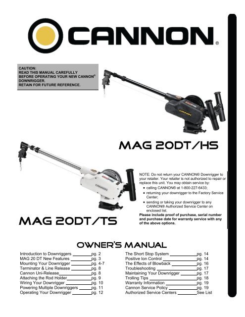
MAG <strong>20DT</strong>/<strong>HS</strong><br />
MAG <strong>20DT</strong>/ts<br />
NOTE: Do not return your CANNON® Downrigger to<br />
your retailer. Your retailer is not authorized to repair or<br />
replace this unit. You may obtain service by:<br />
• calling CANNON® at 1-800-227-6433;<br />
• returning your downrigger to the Factory Service<br />
Center;<br />
• sending or taking your downrigger to any<br />
CANNON® Authorized Service Center on<br />
enclosed list.<br />
Please include proof of purchase, serial number<br />
and purchase date for warranty service with any<br />
of the above options.<br />
Introduction to <strong>Downriggers</strong> pg. 2<br />
MAG 20 DT New Features pg. 3<br />
Mounting Your Downrigger pg. 4-7<br />
Terminator & Line Release pg. 8<br />
<strong>Cannon</strong> Uni-Release pg. 8<br />
Attaching the Rod Holder pg. 9<br />
Wiring Your Downrigger pg. 10<br />
Powering Multiple <strong>Downriggers</strong> pg. 11<br />
Operating Your Downrigger pg. 12<br />
OWNER’S MANUAL<br />
The Short Stop System pg. 14<br />
Positive Ion Control pg. 14<br />
The Effects of Blowback pg. 16<br />
Troubleshooting pg. 17<br />
Maintaining Your Downrigger pg. 17<br />
Trolling Tips pg. 18<br />
Warranty Information pg. 19<br />
<strong>Cannon</strong> Service Policy pg. 19<br />
Authorized Service Centers See List
Introduction to downriggers<br />
Introduction to Controlled Depth Fishing<br />
Undoubtedly there are many fishermen<br />
familiar with the methods and use of controlled<br />
depth fishing. During the mid 1960's the state of<br />
Michigan introduced Pacific salmon into the<br />
Great lakes in an attempt to revitalize its sport<br />
fishing industry. From this successful transplant,<br />
new fishing techniques and equipment were<br />
developed. One such method was controlled<br />
depth fishing which enabled fishermen to place a<br />
lure at a desired depth by utilizing downriggers.<br />
Because of the varying factors (water<br />
temperature, thermocline, weather, tides, time of<br />
day, or time of year) it is necessary for<br />
successful fishing to maintain specific water<br />
depths that coincide with fish movements and<br />
feeding patterns.<br />
One essential feature of the downrigger is<br />
the depth meter or gauge that indicates lure<br />
depth. This allows the angler to control as well<br />
as return to specific depths where fish have<br />
been caught.<br />
Due to the success of controlled depth<br />
fishing, downriggers are now being used<br />
throughout the world to catch a wide variety of<br />
species in both fresh and salt water. Whether<br />
fishing for blues off Rhode Island, walleyes in<br />
Lake Erie, sailfish off the coast of Florida, or<br />
stripers in Tennessee, the use of downriggers<br />
will make your fishing more successful and more<br />
enjoyable.<br />
Attach Line Release to<br />
Rear Hook on Weight<br />
Parts Description<br />
1. Reel This is used to spool the cable, available in lengths ranging from 150 to 400 feet.<br />
2. Boom This is used to extend the weight out from the body of the downrigger and has a pulley fixed<br />
to its end. Boom lengths range from 24 to 53 inches.<br />
3. Swivel Head This relays the cable at the end of the boom to lower the weight.<br />
4. Weight This is used to maintain the depth at which you want to fish. Sizes of weights range from 4 to<br />
20 lbs.<br />
5. Cable This connects to the weight. Cable material is 150 lb. test stainless steel cable.<br />
6. Depth Meter This determines how much cable you have run out, enabling you to choose your trolling<br />
depth.<br />
7. Mounting Base This attaches to the boat, enabling you to place the downrigger where you choose.<br />
2<br />
8. Rod Holder This holds your fishing rods while trolling and may also be used for storing rods.
<strong>Mag</strong> 20 DT New Features<br />
<strong>Mag</strong>num Power<br />
The <strong>Mag</strong> 20 DT/<strong>HS</strong> and <strong>Mag</strong> 20 DT/TS feature<br />
improved tolling weight capacity, retrieval rate,<br />
and quality. The <strong>Mag</strong> 20 DTs can now<br />
accommodate trolling weights up to 20lbs. The<br />
newly improved <strong>Mag</strong> 20 DTs also feature a high<br />
retrieval rate up to 250 feet per minute.<br />
<strong>Mag</strong> 20 DT/TS Features<br />
The <strong>Mag</strong> 20 DT/TS (Tournament Series) has an<br />
improved appearance featuring a sleek metallicwhite<br />
finish. An extremely durable stainless steel<br />
spool allows for you to outfit your downrigger with<br />
monofilament or “super line”, eliminating the fishspooking<br />
vibration and harmonics of conventional<br />
downrigger cables. With a heavy-duty, brushed<br />
stainless steel telescopic boom, adjustable rod<br />
holder, and an Off-Shore Release included, the<br />
<strong>Mag</strong> 20 DT/TS is designed specifically for<br />
tournament level fishing.<br />
Battery Alarm<br />
The <strong>Mag</strong> 20 DT will now beep every two<br />
seconds if the battery voltage drops below 9 volts.<br />
Remote Operation with <strong>Cannon</strong>Link<br />
Your <strong>Mag</strong> 20 DT has the ability to be operated<br />
remotely. Utilizing Humminbird Fishing systems<br />
featuring <strong>Cannon</strong>Link, you can control up to 6<br />
<strong>Mag</strong> 20 DT/<strong>HS</strong>s and/or <strong>Mag</strong> 20 DT/TSs<br />
simultaneously. <strong>Cannon</strong>Link gives you the ability<br />
to cycle downriggers up and down, bottom track,<br />
change depth, monitor speed and temp* (with<br />
<strong>Cannon</strong> Speed & Temp Sensor), and adjust<br />
Positive Ion Control from your Humminbird Fishing<br />
System (Matrix, 700, and 900 Series).<br />
<strong>Cannon</strong>Link Details<br />
The <strong>Mag</strong> <strong>20DT</strong>s connect to the Humminbird<br />
unit with the #019095 <strong>Mag</strong> 20 Master Cable. This<br />
cable has an eight-pin plug on one end and a fivepin<br />
plug on the other. The eight-pin plugs into the<br />
fish finder communication port. Additional <strong>Mag</strong> 20<br />
DTs are connected to each other in a chain with<br />
the #019634 <strong>Mag</strong> 20 Remote Cable. The last<br />
downrigger in the chain must be terminated with<br />
the #609198 Endcap plug that comes with the<br />
<strong>Mag</strong> 20 Master Cable. This plug completes the<br />
loop allowing the fish finder to get depth and mode<br />
information from the <strong>Mag</strong> 20 DTs. Additional<br />
information can be found with the Humminbird fish<br />
finder.<br />
The details of <strong>Cannon</strong>Link are described in full<br />
in your Humminbird owner’s manual. Any one or<br />
all <strong>Mag</strong> 20 DTs can perform these features with<br />
<strong>Cannon</strong>Link only from <strong>Cannon</strong>:<br />
• Set PIC voltage in 1/10ths of volts<br />
• Go to depth (feet or meters)<br />
• Adjustable descent and retrieve speeds<br />
• Cycle mode; includes upper depth, lower<br />
depth and time at depth<br />
• Bottom-contour following mode, includes wave<br />
height, distance above the bottom<br />
• All up (brings all the weights to the surface<br />
immediately)<br />
• Park height (allows you to set individual<br />
heights to park the ball above the water)<br />
• Disconnect alarm sounds if the remote cable<br />
is accidentally unplugged<br />
The <strong>Mag</strong> <strong>20DT</strong>s communicate through an<br />
optically isolated NMEA 0183 standard interface.<br />
Each unit is both a listener and a talker to the next<br />
unit in the chain. The endcap plug sends the last<br />
talker’s broadcast back to the first listener/talker,<br />
which is usually the fish finder. Only two sentence<br />
headers are used: the standard NMEA<br />
‘$SDDBT’ (SONAR Data Depth Below<br />
Transducer) for bottom following, and<br />
‘$PCMAG’ (Proprietary <strong>Cannon</strong> MAG) for system<br />
control. Several features have been included in<br />
the remote interface that would allow the electromechanical<br />
system to be used for other types of<br />
applications.<br />
NEW FEATURES<br />
*Note: The <strong>Cannon</strong>Link system outputs data from only one single<br />
Speed & Temp Sensor Fish.<br />
3
MOUNTING & SETUP<br />
Downrigger Mounting on Boats<br />
A downrigger should be mounted where ever it<br />
is easy to operate and observe. You want to be<br />
able to see your fishing rod and to react quickly.<br />
So, choosing a good spot to mount your<br />
downrigger on your boat is 99% of the job.<br />
Due to the great variety of boats available,<br />
mounting your downrigger can be a dilemma.<br />
Having proper mounting accessories is essential.<br />
<strong>Cannon</strong> has a complete line of mounting<br />
accessories to conveniently mount your<br />
downriggers on any boat.<br />
Arrows<br />
Indicate<br />
Mounting<br />
Locations<br />
Mounting Accessories<br />
Deck Plates are necessary when extra<br />
strength must be added to the base material of<br />
the boat and for attaching the downrigger to other<br />
mounting accessories.<br />
Gimbal Mounts are designed to fit mediumsized<br />
flush mounted rod holders built into the<br />
gunwale of many larger fishing boats and<br />
cruisers. Only sturdy, high quality rod holders<br />
should be used for this temporary mounting<br />
system. Gimbal mounts are available in 9” or 12”<br />
post lengths.<br />
Deck Plate<br />
Gimbal Mount<br />
Clamp Mounts can be mounted at the<br />
junction of two rail sections with the aid of two ¼”<br />
pieces of plywood. They will protect your rail from<br />
any marks from the clamp and provide a non-slip<br />
surface.<br />
Clamp Mount<br />
4
Side Rail Mounting<br />
Side/Rail mounts can be mounted to a<br />
welded T section. They can also be used at the<br />
two rail section butt joint. In both installations it is<br />
recommended to use a non-slip material, such<br />
as rubber or a thin wood sheet, between metal<br />
surfaces.<br />
You can also use these for mounting to a<br />
very narrow side gunwale. There is a plate<br />
provided for back-up with bolts and washers. If<br />
the gunwale compartment is foamed in, then<br />
wellnuts should be used. It is also recommended<br />
to install two additional flat head screws through<br />
the top plate for stabilization (you will need to<br />
drill and countersink).<br />
NOTE: In no case should this mount be used on<br />
fiberglass ¼" thick or less unless it is foamed in.<br />
Side/Rail on T-Section<br />
Side/Rail on Gunwale<br />
MOUNTING & SETUP<br />
Pedestal Mounting<br />
Pedestals are used wherever additional height is<br />
needed for ease of operation or to clear<br />
obstructions, such as handrails.<br />
Caution: When using a pedestal mount or<br />
side/rail mount, do not extend the telescopic<br />
boom on your <strong>Mag</strong> 20 DT. The increased<br />
leverage will cause excessive strain and<br />
possible failure of the mount.<br />
Pedestal for Additional Height<br />
5
MOUNTING & SETUP<br />
Installing the Base on Your Boat<br />
Decks up to 7/16" thick<br />
Where access to the underside of the deck is<br />
not available, the mounting base can be mounted<br />
using wellnuts. Use the base as a template to mark<br />
locations and drill four 1/2" holes. Mount the base<br />
using four 1/4-20 x 4" truss head screws and four<br />
wellnuts. Tighten the screws so the wellnuts are<br />
firmly compressed as pictured.<br />
Decks thicker than 7/16"<br />
For decks thicker than 7/16", or where the<br />
underside of the deck is accessible, mount the base<br />
with screws, nuts, and washers. Use the base as a<br />
template to mark the locations and drill four 9/32"<br />
holes. Use four 1/4-20 x 4" truss head screws and<br />
four each flat washers, lock washers, and nuts.<br />
Fasten the base to the deck as pictured. NOTE:<br />
Wellnuts cannot be used on decks thicker than<br />
7/16".<br />
Decks thinner than 1/4"<br />
Use a <strong>Cannon</strong> deck plate to prevent deflection<br />
and add stability to decks thinner than 1/4". Use the<br />
deck plate as a template to<br />
mark the hole locations.<br />
Decks up to<br />
7/16" Thick<br />
Decks Thicker<br />
Than 7/16" Thick<br />
Screws<br />
Base<br />
Wellnuts<br />
Base<br />
Washer, Lock Washer,<br />
and 1/4-20 Hex Nut<br />
Deck up to 7/16" Thick<br />
Deck Plate<br />
Deck Thicker Than 7/16”<br />
Wellnut<br />
If access to the underside of the deck is not<br />
available, the deck plate can be mounted using<br />
screws and wellnuts. Drill 1/2" holes. Use four 1/4-<br />
20 x 2" flat head screws and four wellnuts to mount<br />
deck plate as pictured. Tighten the screws so the<br />
wellnuts are firmly compressed.<br />
Where the underside is accessible, the deck<br />
plate can be mounted using screws, nuts, and<br />
washers. Drill 9/32" holes. Use four 1/4-20 x 2" flat<br />
head screws, nuts and washers (flat and lock).<br />
Fasten plate to deck as pictured. To secure the<br />
mounting base to the deckplate use four 1/4-20 x 2"<br />
truss head screws.<br />
Washers, Lock<br />
Washers, Screws,<br />
& Nuts<br />
NOTE: When using the telescopic boom, we<br />
strongly recommend the use of a deck plate<br />
on all boats to provide adequate stability for<br />
the downrigger.<br />
The Low-Profile Swivel Base mounting follows the<br />
same procedure as for the deck plate except that<br />
four 1/4”-20 x 2 1/2" truss head screws are used<br />
to fasten the mounting base and four additional<br />
1/4”-20 x 2 1/2" truss head screws fix the swivel<br />
base to the boat deck.<br />
Low-Profile Swivel Base<br />
6
Mounting the Downrigger on the Base<br />
Slide body over the lip of the base, with boom<br />
outboard or facing the stern. Lift Lock Knob to hold<br />
threaded shaft clear of base until body completely<br />
covers base. Turn Lock Knob clockwise to tighten<br />
the downrigger to the base.<br />
Tip: Periodically check base to ensure integrity.<br />
The base should be replaced at least every 5 years.<br />
Setting Up Your Downrigger<br />
Attaching the Boom<br />
Telescopic Boom<br />
The intermediate section of the telescopic boom<br />
must be extended approximately 5" before the<br />
boom locking screw can engage the hole in the<br />
boom. Slip the boom end into the frame and align<br />
the holes. Secure with boom locking screw.<br />
To adjust boom length, with the boom extending<br />
away from you, rotate clamps approximately 1/4<br />
turn counter - clockwise to unlock, and slide boom<br />
section to desired position. To lock, rotate clamp<br />
clock-wise until tight.<br />
The Standard 24 Inch Boom inserts into the<br />
downrigger frame. Be sure that the boom is held<br />
securely by seating it firmly against the shoulder<br />
inside the fame and fastening the boom locking<br />
screw such that it engages the hole in the boom.<br />
Assemble Swivel Head To Boom<br />
Insert the telescopic boom-end into the boomalign<br />
holes and fasten in place with a #8 x 5/8<br />
screw. Spread the swivel head side plates and<br />
slip the assembly over the boom end axle. Snap<br />
the assembly together and install two #4 x 1/2"<br />
screws into the swivel head.<br />
Lock Knob<br />
The Locking Screw Must<br />
Engage Hole in Boom<br />
Clamps<br />
Standard 24"<br />
Boom<br />
3/4"-Long Boom<br />
MOUNTING & SETUP<br />
TIP: Adjusting the angle of the boom head can help<br />
control cable wrap on the reel.<br />
TIP: Whenever downriggers with boom lengths<br />
beyond 24" are used, <strong>Cannon</strong>'s Retro-Ease<br />
Weight Retriever will make bringing in the weight<br />
safe and easy. It attaches to the cable below the<br />
boom end allowing you to pull the weight to yourself<br />
without having to lean way out or collapse the boom<br />
to reach the weight.<br />
Swivel Head<br />
Boom<br />
#8 x 5/8"<br />
Screw (1)<br />
#4 x 1/2"<br />
Screws (2)<br />
7
TERMINATOR & LINE RELEASE<br />
Terminating the Downrigger Cable<br />
Rubber Cushion<br />
Cable<br />
Tip: A set of pliers with wire cutters is<br />
recommended for this part of setup.<br />
Lead cable into<br />
HOLE A.<br />
Pull six inches of<br />
cable through.<br />
Thread cable<br />
through swivel,<br />
then up into<br />
bottom of the<br />
terminator.<br />
Lead cable out of<br />
HOLE B and into<br />
HOLE C. Push the<br />
cable until its end<br />
touches the inside<br />
of the terminator<br />
hook.<br />
HOLE A<br />
Unwind about 2 feet of cable<br />
and thread the cable through<br />
the rubber cushion.<br />
Attach to terminator.<br />
Snap &<br />
Swivel<br />
TIP: Use only straight cable, not kinked.<br />
Tighten cable<br />
by squeezing<br />
terminator<br />
until it snaps<br />
shut. Then<br />
pull at top and<br />
bottom until<br />
drawn tight.<br />
Make sure<br />
that the<br />
cable<br />
threads the<br />
hook.<br />
Swivel<br />
Examine the top of the terminator and note the<br />
order shown in the detail to run cable.<br />
CABLE IN<br />
CABLE IN<br />
CABLE OUT<br />
Slide the cushion over the top of the<br />
terminator and give it a test pull.<br />
The cable is set to attach a <strong>Cannon</strong><br />
Trolling Weight.<br />
<strong>Cannon</strong> Uni-Release<br />
The <strong>Cannon</strong> Uni-Release attaches directly to<br />
the downrigger weight. Attach fishing line to the<br />
clip at the end of the release, and then click<br />
through a series of increasing tension settings.<br />
The release can be used with any test line on salt<br />
or fresh water and may be adjusted from 2 to 22<br />
pounds of grip tension on the line.<br />
Close<br />
Open<br />
Tension<br />
Adjust<br />
Fishing Line<br />
To change line release tension, turn tension<br />
knob to (+) to increase or (-) to decrease. Tension<br />
also may vary according to where the line is<br />
placed in the grips. Higher tension is on the line if<br />
it is set back toward the hinge, and lower if set<br />
closer to the opening. To open the release, spread<br />
the release arms with thumb and forefinger<br />
applying pressure to the sides.<br />
Open<br />
Gripper<br />
Pads<br />
8
Attaching the Rod Holder<br />
The positive lock rod holder incorporates a<br />
locking disk that allows the rod holder to be<br />
aligned in 15 degree increments. Slide the rod<br />
holder tube into the clamp to the desired position<br />
within the recommended area (see below). Be<br />
sure the angled shoulders are facing up. Place<br />
the locking disk into the mating recess of the<br />
frame. Slip the clamp arms in place where the<br />
obround tab on the disk fits into the slot on the<br />
clamp. Slide the star washer between the arm of<br />
the clamp and the frame. Place the flat washer<br />
onto the bolt. Then insert the bolt with washer<br />
through the clamp by entering the disk, going<br />
through the frame, the star washer, and out the<br />
other side of the clamp. Tighten the nut to<br />
secure the rod holder. Reposition the rod holder<br />
by loosening the nut and adjusting the tilt.<br />
CAUTION: This rod holder is intended for use<br />
of up to 30 lb. test line only, and is not<br />
recommended for use with any tackle IGFA<br />
rated higher than 30 lb. A safety strap (not<br />
included) is recommended for all<br />
applications.<br />
The rod holder assembly is not warranted<br />
when used with tackle above 30 lbs.<br />
Equipment placed in the rod holders and the<br />
loss thereof is the responsibility of the user<br />
and is in no way warranted by JOHNSON<br />
OUTDOORS, INC. Mounting must be in<br />
accordance with the above instructions and<br />
diagram to be warranted.<br />
ATTACHING THE ROD HOLDER<br />
Single Rod Holder Assembly<br />
Dual Rod Holder Assembly<br />
Recommended<br />
Area to Clamp<br />
Rod Holder<br />
Star Washer<br />
Placement<br />
Angled<br />
Shoulder<br />
9
WIRING YOUR DOWNRIGGER<br />
Wiring Your Downrigger<br />
Your Boat's Electrical Condition<br />
It is important to make sure that your boat is<br />
properly set up before installing your <strong>Mag</strong> 20 DT<br />
with Positive Ion Control (PIC). Whenever a boat<br />
is in water, various submerged parts interact to<br />
create weak electrical currents. These weak<br />
electrical currents must be controlled to extend<br />
the life of the boat's metal parts and ensure a<br />
good fish catching environment.<br />
Check the zinc sacrificial anodes on your boat<br />
and on the outboard/outdrive. If they are more<br />
than 50% dissolved they should be replaced. Any<br />
coating of slime or growth should be cleaned off.<br />
All metal parts including the hull (if metal) must be<br />
interconnected by a grounding wire. This includes<br />
motor shafts, outdrives, and through hull fittings.<br />
If your boat and zincs are set up correctly, the<br />
voltage on the stainless steel downrigger wire of<br />
your <strong>Mag</strong> 20 DT should be positive when in<br />
contact with the water. The following tips can be<br />
useful:<br />
• Use <strong>Cannon</strong> vinyl coated lead weights. Lead,<br />
if not pure, can produce negative charges.<br />
• Use the trolling weight insulators supplied with<br />
your downrigger. This insulates your weight<br />
from the positive charge on the cable. This will<br />
also ensure that the trolling weight will stop at<br />
water level when retrieved.<br />
• The cable on your downrigger should be<br />
replaced every 2 years. Etching of the cable<br />
can weaken it physically and electrically.<br />
• In saltwater, make sure the sacrificial zincs<br />
are replaced when half dissolved. This<br />
ensures that the boat will run with a neutral or<br />
slightly positive charge. Clean zincs on a<br />
regular basis with a non-corrosive brush.<br />
• Always make sure the boat is properly<br />
grounded to the water. This will help ensure<br />
proper PIC voltage on the cable and that the<br />
Short Stop will function properly.<br />
Note: You must unplug the <strong>Mag</strong> 20 DT to check<br />
the natural voltage on the reel cable.<br />
Electrical Specifications & Wiring<br />
Instructions<br />
The <strong>Mag</strong> 20 DT is rated at 25 amps (full load),<br />
12 volts DC and is protected by a 30 amp manual<br />
reset circuit breaker (located under motor housing).<br />
Be sure to measure the battery voltage of your boat.<br />
WARNING! - DO NOT RUN THIS DOWNRIGGER<br />
ON A 24 VOLT BATTERY SYSTEM. THIS WILL<br />
DAMAGE THE UNIT AND VOID YOUR<br />
WARRANTY.<br />
Connecting to the Battery:<br />
It is strongly recommended that a fuse or<br />
manual-reset circuit breaker be installed at the<br />
battery on the positive lead of the power cable or<br />
that you connect the downrigger to a battery<br />
selector switch. (See Fuse and Wire Specifications)<br />
Connect the positive lead (RED) to the (+) post on<br />
your battery or the downrigger will not operate. Use<br />
the new quick disconnect plug to remove the<br />
downrigger without touching the battery.<br />
NOTE: It is strongly recommended to power your<br />
<strong>Mag</strong> 20 DT with a Deep-Cycle marine battery. Only<br />
run a <strong>Mag</strong> 20 DT from a Starter battery if is<br />
recharged by an alternator while trolling with the<br />
outboard motor.<br />
Tip: Control degradation of the power cables and<br />
limit corrosion by using <strong>Cannon</strong> Ox-Not antioxidant<br />
gel on all connections.<br />
10
FUSE / BREAKER SPECIFICATIONS:<br />
30 Amp, 32 Volt, waterproof, fast blow.<br />
WIRE SPECIFICATIONS:<br />
0-15 ft. (0-5 meters) 10 gauge<br />
15-25 ft. (5-8 meters) 8 gauge<br />
25-30 ft. (8-9 meters) 6 gauge<br />
CAUTION: When using wire longer than that<br />
provided with your unit, follow the above chart.<br />
When running more than 30 feet from the<br />
battery, contact a qualified electrician.<br />
Powering Multiple <strong>Downriggers</strong><br />
When operating multiple <strong>Mag</strong> 20 DTs, run a<br />
maximum of 2 downriggers per dedicated<br />
battery. The advanced features of the <strong>Mag</strong> 20 DT<br />
can keep the unit working virtually all the time. (See<br />
below for the recommended wiring setup.)<br />
Battery<br />
Battery<br />
Fuse Holder<br />
Circuit Breaker<br />
Red ( - )<br />
WIRING YOUR DOWNRIGGER<br />
NOTE: To ensure proper operation of your <strong>Mag</strong><br />
20 DT, ground its battery to your boat’s electrical<br />
system’s ground. Malfunctions with the PIC,<br />
communication between units, or loss of<br />
operation result from faulty grounding. Always<br />
check to see if your boat is properly grounded<br />
first.<br />
Red ( + )<br />
Black ( – )<br />
Connect<br />
Multiple<br />
Batteries in<br />
Parallel<br />
Typical Operating Time*:<br />
1 <strong>Mag</strong> 20 DT per battery – 24 hours.<br />
2 <strong>Mag</strong> 20 DTs per battery – 10 hours.<br />
*Time based on lab results using a 15lb weight<br />
and Deep-Cycle batteries. Actual run time will<br />
vary.<br />
FOR MAXIMUM PERFORMANCE:<br />
Use Minn Kota Group 27 or 31 sized, Deep-Cycle<br />
marine batteries. For extended battery life, add a<br />
Minn Kota on-board, DC alternator charger.<br />
11
OPERATING YOUR DOWNRIGGER<br />
Operating Your Downrigger<br />
After mounting the <strong>Cannon</strong> downrigger to your<br />
boat, release some line from your rod and reel so<br />
that the lure is anywhere from 5 to 100 feet<br />
behind the boat. Tthis is called drop back.<br />
Attach the fishing line firmly into the line<br />
release. Press and hold the toggle switch down to<br />
lower the weight to the desired depth as indicated<br />
on the depth meter. Place the fishing rod in the<br />
rod holder and reel up the slack so that your rod<br />
has a slight bend in it. When a fish strikes the<br />
lure, the line will separate from the release. Then<br />
you will be free to fight the fish and bring it in on<br />
your rod and reel.<br />
Lowering the Weight<br />
The <strong>Mag</strong> 20 DT can lower the trolling weight<br />
manually or powered.<br />
<strong>Manual</strong> Descent: Fast or Slow<br />
By turning the clutch knob gently clockwise<br />
(toward the boom), you can let your trolling weight<br />
descend as fast or as slowly as you wish. Turning<br />
the knob counterclockwise (away from the boom)<br />
stops the weight. This gives you control to let it<br />
plunge rapidly or sink slowly to a predetermined<br />
trolling depth. With multiple downriggers, you<br />
could start all your weights creeping down, one at<br />
a time, and then stop them each in turn.<br />
Clutch Knob<br />
To Lower<br />
Weight<br />
3-Position<br />
Motor Switch<br />
Powered Descent: One speed fits all<br />
Hold the toggle switch down until the weight<br />
reaches the desired depth and release. The motor<br />
will stop when switch is released or moved to the<br />
neutral position.<br />
3-Position<br />
Motor<br />
Switch<br />
12
NOTE: Make sure that the clutch is well tightened<br />
when using powered descent or ascent.<br />
NOTE: Actual fishing depth may vary from depth<br />
shown on meter due to trolling speed and weight of<br />
cannon ball. (See "Blowback")<br />
NOTE: If your reel continues to slip no matter how<br />
hard you tighten the brake adjust knob, try this<br />
suggestion.<br />
1. Unwind the cable from the reel and remove the<br />
set screw.<br />
2. Align set screw hole in reel with reel shaft hole<br />
by inserting 3/16" or smaller rod. Rotate the reel<br />
until you feel the rod drop into the shaft hole.<br />
3. Replace the set screw and tighten until you feel<br />
resistance.<br />
4. By gently rocking the reel back and forth while<br />
you finish tightening the set screw, you can feel<br />
it engage the shaft hole. The half dog point on<br />
the set screw MUST enter the shaft hole, not<br />
just be tightened against the shaft.<br />
Caution: The brake adjust knob (clutch) should<br />
be adjusted so that it is tight enough to hold the<br />
weight and the lure at the speed you are<br />
trolling. Over tightening may cause damage to<br />
your downrigger when weight hangs up on<br />
bottom structure or other obstacles.<br />
Raising the Weight<br />
Push the toggle switch up momentarily and<br />
release. The weight will rise until it reaches the<br />
surface and then automatically stop.<br />
If you want to raise the weight farther push the<br />
toggle switch up and hold until the weight reaches<br />
the desired position, then release.<br />
To stop the weight during ascent, push the<br />
toggle switch down momentarily (approximately 1<br />
second).<br />
Adjusting the Depth Meter<br />
The <strong>Cannon</strong> Depth Meter provides non-slip<br />
accuracy, plus easy resetting. To reset, just slide<br />
the meter away from the reel until the gears are<br />
disengaged. Spin meter gear to change setting.<br />
Raise<br />
Off<br />
Lower<br />
Depth Meter<br />
OPERATING YOUR DOWNRIGGER<br />
13
THE SHORT STOP SYSTEM<br />
The Short Stop System<br />
The Short Stop system is composed of three<br />
critical components: the electronic unit, the reel set<br />
screw, and the trolling weight insulator.<br />
While the downrigger cable is in the water, there<br />
is a minute electrical current that flows between the<br />
cable and the grounded metal boat components in<br />
the water. When the cable clears the water, this<br />
current flow will stop. The Short Stop system senses<br />
this interruption and turns off the motor. The trolling<br />
weight insulator is used to break the cable contact to<br />
the water while the weight is still in the water. The<br />
reel set screw allows the circuit path to be made<br />
through the structure of the downrigger.<br />
NOTE: It may be necessary to use two trolling<br />
weight insulators.<br />
Stopping the weight at water level eliminates the<br />
cable strain caused by bouncing weights or weights<br />
hitting the boom end. Stopping at water level will<br />
also keep the weight from hitting the boat hull.<br />
1/16"<br />
Short Stop System<br />
Cable<br />
Terminator<br />
The Positive Ion Control System<br />
Your boat has an electrical charge around the<br />
hull in water. If a boat is properly bonded and<br />
properly zinced, that charge should be slightly<br />
positive when measured from ground to the<br />
downrigger cable. Positive Ion Control (PIC) is the<br />
use of electricity to control that charge and its<br />
fluctuation so that it is always maintained at a<br />
specified set voltage.<br />
Weight<br />
Insulator<br />
The practice of setting up and maintaining a<br />
slight positive charge on fishing gear has been used<br />
by commercial fishermen for many years. This<br />
practice has enabled some fisherman to increase<br />
yield when used along with other good fishing and<br />
boating practices.<br />
14<br />
<strong>Cannon</strong>’s electric downriggers offer fishermen a<br />
big advantage in being able to stabilize and control<br />
the positive charge around their boat. Because of<br />
the Lexan® construction of the frame, <strong>Cannon</strong><br />
downriggers are insulated from your boat’s hull<br />
charge. When the stainless steel downrigger cable is<br />
lowered into the water, the natural ionization<br />
between the cable and the boat creates a positive<br />
charge of 0.7 to 0.9 volts in saltwater and 0.3 to 0.6<br />
volts in fresh water. This natural voltage is<br />
dependent upon salinity and mineral content of the<br />
water. Your actual voltage may vary.<br />
NOTICE: Short stop and Positive Ion<br />
Control features do not function when<br />
spooled with monofilament or super<br />
lines.
How the Positive Ion Control System Works<br />
The PIC system uses an internal circuit that<br />
passes the voltage through the drive train of the<br />
<strong>Mag</strong> 20 DT to the reel set screw. The set screw<br />
contacts the cable. Care must be taken to ensure<br />
contact between the cable and the set screw<br />
when replacing the cable.<br />
The positive Ion Control system applies a<br />
variable 0.2 to 1.2 volts on the trolling cable at all<br />
times. To adjust the Positive Ion Control, simply<br />
turn the PIC knob on the back of the <strong>Mag</strong> 20 DT<br />
housing (see below).<br />
Measuring the Natural Electrolysis and PIC<br />
Voltage on Your Boat<br />
A voltmeter with a scale of zero to one volt will<br />
measure the natural electrolysis. Place the ground<br />
lead of the meter on the motor or the battery<br />
ground. Place the positive lead on the stainless<br />
steel downrigger cable while it is in the water. The<br />
downrigger must be unplugged. The voltage you<br />
measure on the volt meter is your boat’s natural<br />
electrolysis voltage. Use the same set up to<br />
measure the PIC voltage; just plug in the <strong>Mag</strong> 20<br />
DT and adjust the PIC knob to the voltage<br />
desired.<br />
Data In<br />
Positive Ion Control<br />
(PIC) Knob<br />
Data Out<br />
POSITIVE ION CONTROL<br />
Using Positive Ion Control<br />
Positive Ion Control is very effective when<br />
trolling. The zone of attraction created at the<br />
downrigger wire will attract the fish. It is best to<br />
use a short drop back between the downrigger<br />
release and the lure. Drop backs of 10 to 20 ft. are<br />
typical. A drop back of 50 to 100 ft. will entirely<br />
negate the effects of the PIC circuit. Fishing<br />
depths greater than 125 ft. may require a slightly<br />
higher PIC voltage. If you return to shallow water<br />
fishing remember to turn the PIC voltage down<br />
again.<br />
The correct PIC setting for your best fishing<br />
advantage varies, depending on fish type and<br />
location. For example, the proper setting for Puget<br />
Sound Steelhead may not be effective for Great<br />
Lakes Steelhead. To fully benefit from PIC<br />
technology, it is important that you experiment<br />
with the PIC setting to find the proper voltage for<br />
the gamefish in your area. For more information<br />
on this subject, refer to “Secrets of Fishing with<br />
Electricity” by Ollie Rode.<br />
15
Blowback<br />
Blowback<br />
Simply stated, blowback is what happens to<br />
the downrigger weight when you pull it through the<br />
water behind your boat. As your speed increases,<br />
so does the horizontal distance between the<br />
weight and your downrigger. The faster you go,<br />
the farther the weight is behind you. The farther<br />
the weight is behind you, the shallower the weight<br />
is.<br />
The following charts provide you with<br />
blowback information for three sizes of <strong>Cannon</strong><br />
downrigger weights pulled at three different<br />
speeds with no lures attached and with no current.<br />
Current drag, water salinity and the use of non-<br />
<strong>Cannon</strong> products will affect your actual trolling<br />
depth.<br />
As an example, the first chart shows that if you<br />
are trolling at 4 MPH with an 8 pound weight and<br />
you have 100 FT. of cable in the water with no<br />
current; the downrigger ball is actually at a depth<br />
of about 80 FT.<br />
Actual Depth of Weight (ft.)<br />
Blowback Charts<br />
8-Lb. Weight at 2, 4, and 6 MPH<br />
Amount of Cable in Water (ft.)<br />
10-Lb. Weight at 2, 4, and 6 MPH<br />
2 MPH<br />
4 MPH<br />
6 MPH<br />
2 MPH<br />
ActualDepth of Weight (ft.)<br />
4 MPH<br />
6 MPH<br />
Amount of Cable in Water (ft.)<br />
12-Lb. Weight at 2, 4, and 6 MPH<br />
2 MPH<br />
Actual Depth of Weight (ft.)<br />
4 MPH<br />
6 MPH<br />
16<br />
Amount of Cable in Water (ft.)
Trouble Shooting<br />
PROBLEM:<br />
Up or down will not work.<br />
SOLUTION:<br />
Check the battery cable polarity then check<br />
the battery voltage. A properly connected and<br />
charged battery is important for safety and for<br />
proper operation of the downrigger.<br />
PROBLEM:<br />
The <strong>Mag</strong> 20 DT/<strong>HS</strong> \ <strong>Mag</strong> 20 DT/TS fails to<br />
continue running after toggle switch is pushed<br />
up and held momentarily, while cable is still in<br />
water, or is having problems with the PIC<br />
voltage.<br />
SOLUTION:<br />
Make sure your boat is properly bonded. A<br />
boat that is properly bonded has an electrical<br />
path from the negative battery terminal to all<br />
metal parts on the boat that contact water.<br />
Additionally, in saltwater the boat must be<br />
properly zinced to show a natural electrolysis<br />
voltage of 0.7 to 0.9 volts. The voltage supply<br />
to your downrigger must also be bonded to<br />
the boat.<br />
PROBLEM:<br />
Clutch slips<br />
SOLUTION:<br />
The set screw in the reel may have come<br />
loose off the shaft. Follow the instructions<br />
below:<br />
1) Unwind the cable from the reel.<br />
2) Remove the set screw.<br />
3) Align the set screw hole in the reel with the<br />
hole in the reel shaft by inserting a 3/16" or<br />
smaller rod and rotating the reel until you feel<br />
it drop into the shaft hole.<br />
4) Replace the set screw and tighten until you<br />
feel resistance.<br />
5) By gently rocking the reel back and forth while<br />
tightening the set screw, you can feel it<br />
engage in the shaft hole. The half dog point<br />
on the set screw must enter the hole in the<br />
shaft; not just be tightened against the reel<br />
shaft.<br />
6) The set screw should be about 1/16" above<br />
the top of the hole when it is properly seated<br />
(not so for TS models). The contact between<br />
the stainless steel cable and the set screw is<br />
important for proper operation of the Positive<br />
Ion Control system.<br />
Maintaining Your Downrigger<br />
Periodically, lightly grease the thrust bearing<br />
and bearing race found behind the clutch knob.<br />
Replace the cable at least every two years.<br />
There are no other user serviceable parts on<br />
the <strong>Mag</strong> 20 DTs. Your warranty will be void if<br />
the seal on your unit is broken. For repairs or<br />
servicing your downrigger refer to the<br />
Warranty Information section of this booklet.<br />
TROUBLESHOOTING & MAINTAINING<br />
17
TROLLING TIPS<br />
Ten Good Trolling Tips<br />
1) Test your lures over the boat side before<br />
sending them down and back. Do this to make<br />
sure the lure wiggles and wobbles properly<br />
without going belly up or wandering off. Some<br />
lures can be adjusted, fine tuned actually, to<br />
impart maximum action. For example, a slight<br />
bend in the tail of a spoon or twist of the hook eye<br />
in the nose of a plug can make a noticeable<br />
difference in how the lure performs.<br />
Also, when running two or more lures, make sure<br />
the offerings are compatible. Lures that run out of<br />
harmony with each other are bound to tangle and<br />
that means wasted time to straighten out the<br />
mess. Testing them first will avoid the problem.<br />
2) Consider different sizes, shapes, and colors<br />
of lures. No one has ever figured out with<br />
precision what makes a fish strike or snub a lure.<br />
There is no doubt, that matching the forage<br />
(minnows, crayfish, etc.) in color, shape, action,<br />
and size can help trigger those strikes from<br />
hungry fish. On the other hand, if fish such as<br />
bluegills, small mouth bass or Coho salmon are<br />
protecting spawning beds, they may attack<br />
whatever is threatening. So, bright colors in lures<br />
may out produce bland colors.<br />
3) Vary trolling speeds. Goosing the engine<br />
now and then or slowing to a crawl every so often<br />
will change the action of the lures and may get<br />
fish to strike them.<br />
4) Vary trolling patterns and lead lengths. The<br />
amount of line you let out often determines how<br />
deep the lure will run and, to some extent, what<br />
degree of action it will impart. For starters,<br />
consider running lures about ten feet behind<br />
downrigger weights. If flat line trolling, put them<br />
back about fifty feet, then experiment depending<br />
on what the fish do.<br />
Trolling patterns affect lure action too, that is<br />
why some anglers like to wheel a lazy S course.<br />
On turns, outside lures will speed up momentarily<br />
while inside lures hang for a moment or two. Fish<br />
may nail lures that change speeds. Also, zigzag<br />
patterns allow for more water coverage, plus it<br />
keeps lures out of propeller boil, an important<br />
consideration for browns and other wary species.<br />
5) Locate fish on a vertical plane. Place lures<br />
in areas where fish might be. Skilled fishermen<br />
call these areas the “strike zones”. They include<br />
the edges of the week beds, structure along<br />
bottom, drop-offs, preferred temperature of the<br />
target species, and the thermocline. Remember<br />
that fish occupy certain areas for certain reasons<br />
(sources of food, protective cover, preferred<br />
temperatures, etc.).<br />
6) Consider special knots and swivels. A<br />
good ball bearing swivel will all but eliminate line<br />
twist and will aid in getting maximum performance<br />
from a lure. Many anglers add the tiny swivels to<br />
split rings already on the lure itself. On the other<br />
hand, a swivel may dampen the action of a<br />
sensitive lure, such as a Rapala. Some fisherman<br />
tie tiny improved cinch or loop knots. Loop knots<br />
in particular may enhance up and down and side<br />
to side action of lures. Any good fishing manual<br />
will explain how to tie these and other knots.<br />
7) Consider releases for flatline trolling. A<br />
good tip is to secure a piece of downrigger cable<br />
or heavy monofilament to the water ski hook or<br />
handle below the transom of most boats. To the<br />
other end of the mono or cable, add a pinch-rrelease.<br />
After letting out your lure to the desire<br />
distance, put the rod in its holder, then bend the<br />
tip and secure the fishing line in the release.<br />
8) Add a weed guard. Having trouble with<br />
weeds hanging up lures Consider tying a threeinch<br />
piece of monofilament a foot above the lure.<br />
Leaves, smaller weeds and other debris may<br />
catch here momentarily then fall off to the side of<br />
the lure without tangling. Weedless lures are<br />
another smart consideration. Downrigger cables<br />
are effective weed catchers when trolling for pike,<br />
muskies, or bass in weed-infested lakes.<br />
9) Add a stinger hook. When fish short strike,<br />
slap at lures without becoming hooked, adding a<br />
stinger hook can solve the problem. Simply tie a<br />
treble hook to one end of a four inch piece of<br />
monofilament and then tie the extra hook to the<br />
last gang of hooks on your lure. The stinger hook,<br />
which trails the lure, provides extra insurance.<br />
10) Keep hooks sharp. Some of the best<br />
fishermen sharpen all hooks after every fish<br />
caught. Hooks get dull through both use and<br />
misuse, and probably more fish are lost to dull<br />
points than anything else.<br />
18
CANNON® LIMITED WARRANTY<br />
Johnson Outdoors Inc. warrants to the original purchaser that if the<br />
accompanying product (see exclusions below) proves to be defective<br />
in material or workmanship within the following warranty periods,<br />
Johnson Outdoors Inc. will, at its option, either repair or replace same<br />
without charge (but no cash refunds will be made):<br />
1) The boom, motor, and reels, plus all Lexan®* parts, including<br />
but not limited to frames and bases, will be free from defects in<br />
materials and workmanship, subject to normal wear and tear,<br />
for the original purchaser's lifetime.<br />
2) All other items will have 1-year limited warranties from the<br />
date of original retail purchase, except THE FOLLOWING<br />
ITEMS THAT HAVE NO WARRANTY WHATSOEVER: boot<br />
covers, clothing, Dacron line, rubber bands, swivel lock pin,<br />
weights, and wire cable.<br />
This limited warranty may be enforced only by the original<br />
purchaser; all subsequent purchasers acquire the product "as<br />
is" without any benefit of this limited warranty. Repair or<br />
replacement of the product as set forth in this limited warranty<br />
shall be the original purchaser’s sole and exclusive remedy<br />
and Johnson Outdoors Inc.’s sole and exclusive liability for<br />
breach of this warranty.<br />
EXCLUSIONS<br />
This warranty does not apply in the following circumstances:<br />
• When the product has been connected, installed, combined,<br />
altered, adjusted, serviced, repaired, or handled in a manner<br />
other than according to the instructions furnished with the<br />
product<br />
• When the motor housing is opened by anyone other than<br />
<strong>Cannon</strong> ® Authorized service repair personnel.<br />
• When any defect, problem, loss, or damage has resulted from<br />
any accident, misuse, negligence, carelessness, or abnormal<br />
use, or from any failure to provide reasonable and necessary<br />
maintenance in accordance with the instructions of the owner's<br />
manual<br />
LIMITATION AND EXCLUSION OF IMPLIED WARRANTIES AND<br />
CERTAIN DAMAGES<br />
THERE ARE NO EXPRESS WARRANTIES OTHER THAN<br />
THESE LIMITED WARRANTIES. JOHNSON OUTDOORS INC.<br />
DISCLAIMS LIABILITY FOR INCIDENTAL AND CONSEQUENTIAL<br />
DAMAGES, AND IN NO EVENT SHALL ANY IMPLIED<br />
WARRANTIES (EXCEPT ON THE BOOM, MOTOR, REELS, AND<br />
ALL LEXAN®* PARTS), INCLUDING ANY IMPLIED WARRANTY OF<br />
MERCHANTABILITY OR FITNESS FOR PARTICULAR PURPOSE,<br />
EXTEND BEYOND ONE YEAR FROM THE DATE OF PURCHASE<br />
(AND IN THE CASE OF THE BOOT COVERS, CLOTHING, DACRON<br />
LINE, RUBBER BANDS, SWIVEL LOCK PIN, WEIGHTS, AND WIRE<br />
CABLE, JOHNSON OUTDOORS INC. DISCLAIMS ALL IMPLIED<br />
WARRANTIES). THIS WRITING CONSTITUTES THE ENTIRE<br />
AGREEMENT OF THE PARTIES WITH RESPECT TO THE<br />
SUBJECT MATTER HEREOF; NO WAIVER OR AMENDMENT<br />
SHALL BE VALID UNLESS IN WRITING SIGNED BY JOHNSON<br />
OUTDOORS INC.<br />
Some states do not allow limitations on how long an implied warranty<br />
lasts or the exclusion or limitation of consequential damages, so the<br />
above limitation or exclusion may not apply to you. This warranty gives<br />
you specific legal rights, and you may also have other rights that vary<br />
from state to state.<br />
* Lexan is a registered trademark of General Electric.<br />
CANNON ® SERVICE POLICY<br />
AFTER THE APPLICABLE WARRANTY PERIOD<br />
After the applicable warranty period, or, if one of the above<br />
exclusions applies, <strong>Cannon</strong>® products will be repaired for a charge of<br />
parts plus labor. All factory repairs, after the applicable warranty<br />
period, carry a 90-Day Limited Warranty, subject to the exclusions and<br />
limitations stated above.<br />
TO ENFORCE WARRANTY OR TO<br />
OBTAIN REPAIRS AFTER WARRANTY<br />
To obtain warranty service in the U.S., the downrigger or part<br />
believed to be defective and the proof of original purchase (including<br />
the date of purchase) must be presented to a <strong>Cannon</strong>® Authorized<br />
Service Center or to <strong>Cannon</strong>®’s factory service center in Mankato,<br />
MN. Except as noted below, any charges incurred for service calls,<br />
transportation or shipping/freight to/from the <strong>Cannon</strong>® Authorized<br />
Service Center or <strong>Cannon</strong>®’s factory, labor to haul out, remove, reinstall<br />
or re-rig products for warranty service, or any similar items are<br />
the sole and exclusive responsibility of the purchaser. <strong>Downriggers</strong><br />
purchased outside of the U.S. (or parts of such downriggers) must be<br />
returned prepaid with proof of purchase (including the date of<br />
purchase and serial number) to any Authorized <strong>Cannon</strong>® Service<br />
Center in the country of purchase. Warranty service can be arranged<br />
by contacting a <strong>Cannon</strong>® Authorized Service Center listed on the<br />
enclosed sheet, or by contacting the factory at 1-800-227-6433 or Fax<br />
1-800-527-4464. If the necessary repairs are covered by the warranty,<br />
we will pay the return shipping charges to any destination within the<br />
United States.<br />
DO NOT return your <strong>Cannon</strong> ® downrigger or parts to your retailer.<br />
Your retailer is not authorized to repair or replace them.<br />
Major parts, such as the motor and main frame, must be returned<br />
to Johnson Outdoors Inc. in Mankato, Minnesota, or a <strong>Cannon</strong> ®<br />
Authorized Service Center, for repair or replacement. To reduce<br />
shipping costs, we suggest removal of loose parts such as the boom<br />
and rod holders. Small parts that can be easily removed such as the<br />
handle and/or the counter, may be removed from the downrigger and<br />
returned for repair or replacement.<br />
Retain your sales receipt! Proof of purchase must accompany<br />
product when returned.<br />
Return Address:<br />
FOR YOUR INFORMATION:<br />
Johnson Outdoors Inc.<br />
<strong>Cannon</strong> Division<br />
121 Power Drive<br />
Mankato, MN 56001<br />
Serial No.<br />
Date Purchased<br />
Store Where Purchased<br />
RETAIN THIS SECTION FOR YOUR RECORDS<br />
LIMITED WARRANTY & SERVICE POLICY<br />
19
ENVIRONMENTAL COMPLIANCE STATEMENT:<br />
It is the intention of Johnson Outdoors Inc. to be a responsible corporate citizen, operating in compliance with known and applicable<br />
environmental regulations, and a good neighbor in the communities where we make or sell our products.<br />
WEEE Directive:<br />
EU Directive 2002/96/EC “Waste of Electrical and Electronic Equipment Directive (WEEE)” impacts most distributors, sellers, and manufacturers<br />
of consumer electronics in the European Union. The WEEE Directive requires the producer of consumer electronics to take responsibility<br />
for the management of waste from their products to achieve environmentally responsible disposal during the product life cycle.<br />
WEEE compliance may not be required in your location for electrical & electronic equipment (EEE), nor may it be required for EEE designed<br />
and intended as fixed or temporary installation in transportation vehicles such as automobiles, aircraft, and boats. In some European Union<br />
member states, these vehicles are considered outside of the scope of the Directive, and EEE for those applications can be considered excluded<br />
from the WEEE Directive requirement.<br />
This symbol (WEEE wheelie bin) on product indicates the product must not be disposed of with other household refuse.<br />
It must be disposed of and collected for recycling and recovery of waste EEE.<br />
Johnson Outdoors Inc. will mark all EEE products in accordance with the WEEE Directive. It is our goal to comply in the collection,<br />
treatment, recovery, and environmentally sound disposal of those products; however, these requirement do vary within European<br />
Union member states. For more information about where you should dispose of your waste equipment for recycling and<br />
recovery and/or your European Union member state requirements, please contact your dealer or distributor from which your product<br />
was purchased.<br />
To download product manuals or purchase <strong>Cannon</strong> products from an authorized dealer, please visit our web page at<br />
www.cannondownriggers.com<br />
Johnson Outdoors, Inc. / <strong>Cannon</strong> Division<br />
121 Power Drive, Mankato, MN 56001<br />
1-800-227-6433<br />
© 2008 Johnson Outdoors, Inc. All rights reserved.<br />
All CANNON <strong>Downriggers</strong> are covered by US Pat.D-269, 992. Copyright 2006 Johnson Outdoors, Inc. All rights reserved.<br />
Conforms to 89/336/EEC (EMC) under standards EN 55022A, EN 50082-2 since 1996 LN V9677264<br />
WARNING: This product contains chemical(s) known to the state of California to cause cancer and/or reproductive toxicity.<br />
20<br />
Form No. 3397101 Rev D