CA1 ⢠CA1T - Full Compass
CA1 ⢠CA1T - Full Compass
CA1 ⢠CA1T - Full Compass

You also want an ePaper? Increase the reach of your titles
YUMPU automatically turns print PDFs into web optimized ePapers that Google loves.
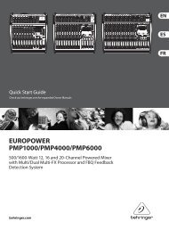
are meant for the connection of condenser type microphones that use 24V phantom<br />
power, dynamic microphones (30-600 ohms) or a high level sound source (e.g. AM/<br />
FM tuner, cassette desk, CD player, etc.). In case you are using it is necessary to use<br />
the switch (26).<br />
Note: Connecting unbalanced microphones to the amplifier when the phantom is<br />
switched on could lead to severe damage on the microphones and is therefore not<br />
2<br />
3<br />
1<br />
2<br />
3<br />
1<br />
Balanced<br />
Microphone<br />
3-pin XLR<br />
(seen from the soldered side)<br />
Unbalanced<br />
Microphone<br />
3-pin XLR<br />
(seen from the soldered side)<br />
Balanced<br />
Microphone<br />
Stereo Jack (TRS)<br />
Unbalanced<br />
Microphone<br />
1/4-inch Mono Phone Plug<br />
recommended. It is absolutely mandatory to perform any plugging or unplugging of<br />
microphone cables with the phantom power turned off. Also, make sure that the phantom<br />
power is turned off when using microphones that are not meant to be operated<br />
with phantom power. The voltage is present on pin2 and pin3 of the XLR-connector<br />
could lead to severe damages on the microphones. When in doubt, please consult<br />
the owner’s manual of the questionable microphone or contact your dealer before you<br />
perform any connections.<br />
24. AM Loop Antenna (<strong>CA1</strong>T Only)<br />
This antenna for receives AM frequency band waves.<br />
25. FM Antenna (<strong>CA1</strong>T Only)<br />
This antenna for receives FM frequency band waves.<br />
26. INPUT 2, INPUT 3 and INPUT 4 lnputs Sensitivity and XLR<br />
Phantom Power 24V Switch<br />
By turning these switchs to the LINE position INPUT 2, INPUT 3 and INPUT4 can be<br />
connected to an audio source with high level signal output. By turning these switches<br />
to the MIC position the INPUT 2, INPUT 3 and INPUT4 can be connected to a dynamic<br />
microphone with low impedance. By selecting the switch to the 24V position,<br />
connects the 24V phantom supply on the XLR (pin2 and pin3) of INPUT 2, INPUT 3<br />
and INPUT4. This is necessary to operate condenser type microphones which require<br />
this type of external supply.<br />
It is recommended to use this switch with the master volume set to minimum.<br />
27. lnput Sensitivity Switch (AUX1, AUX2)<br />
By setting these switches onto the “1” position the AUX1 and AUX2 inputs are suitable<br />
for connecting a CD-player. By setting these switches onto the “2” position the<br />
AUX1, AUX2 input is suitable for connecting an AM/FM radio signal output. By setting<br />
these switches onto the “3” position, the AUX1, AUX2 input are suitable for connecting<br />
to a desktop cassette player signal output. By setting these switches to the “4” position,<br />
the AUX1, AUX2 input are suitable for connected high-level signal outputs.<br />
28. Telephone Paging Input Level Control<br />
This control allows you to set the volume of the sound source that is connected to the<br />
9