S.A.S LECOMBLE & SCHMITT - PYI Inc.
S.A.S LECOMBLE & SCHMITT - PYI Inc.
S.A.S LECOMBLE & SCHMITT - PYI Inc.

You also want an ePaper? Increase the reach of your titles
YUMPU automatically turns print PDFs into web optimized ePapers that Google loves.
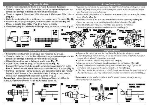
Par raccord à visser<br />
Séparer l’écrou tournant, la douille et la nipple du raccord du groupe.<br />
Visser la partie raccord sur les utilisations du groupe en respectant les<br />
couples de serrage indiqués (voir schéma de cablage).<br />
Tracer un repère à 21 mm pour ∅ int. 8 mm ou à 30 mm pour ∅ int. 10 mm<br />
(Fig. C).<br />
Huiler le bout du flexible et le bloquer en rotation sans l’écraser (Fig. D).<br />
Visser la douille jusqu’au repère, sens de rotation anti-horaire (Fig. D).<br />
Placer la douille dans l’étau (Fig. E) et huiler la nipple.<br />
Visser la nipple jusqu’à la limite du filetage, sens de rotation horaire (Fig. F).<br />
Screwed connection<br />
Separate the swivel nut, the sleeve and the nipple from the fitting for the power pack.<br />
Screw the fitting (union piece) in the power pack outlets as per the indicated torque<br />
(see hydraulic connection drawing).<br />
Mark a point of reference at 21 mm for 8 mm inner Ø tube or 30 mm for 10 mm<br />
inner Ø tube (Dwg C).<br />
Lubricate the end of the tube and immobilize it without squeezing it (Dwg D).<br />
Screw the sleeve up to the marking in anticlockwise direction (Dwg D).<br />
Immobilize the sleeve in a vice (Dwg E) and lubricate the nipple.<br />
Screw the nipple to the thread end in clockwise direction (Dwg F).<br />
Par raccord à sertir<br />
Séparer l’écrou tournant et la bague des raccords du groupe.<br />
Visser la partie raccords sur les utilisations du groupe en respectant les<br />
couples de serrage indiqués (voir schéma de cablage).<br />
Glisser l’écrou tournant et la bague sur le tube (Fig. G).<br />
Visser l’écrou tournant jusqu’en début de butée (Fig. H).<br />
Enfoncer fermement le tube dans le corps du raccord jusqu’en butée.<br />
Puis à l’aide d’une clé, serrer l’écrou tournant d’environ 1 ½ tour (Fig. I).<br />
Contrôle : démonter l’écrou tournant. Une collerette visible doit remplir<br />
l’espace situé devant la face avant de l’arête. La bague peut tourner,<br />
mais aucun déplacement axial n’est autorisé (Fig. J).<br />
Remontage : visser l’écrou tournant sur le raccord jusqu’en début de<br />
butée puis serrer d’environ 1/8 de tour à l’aide d’une clé.<br />
Crimp connection<br />
Separate the swivel nut and the ring from the fittings for the power pack.<br />
Screw the fittings (union pieces) in the power pack outlets as per the indicated<br />
torque. (See hydraulic connection drawing).<br />
Slip the swivel nut and the ring on the tube (Dwg G).<br />
Screw on the swivel nut until it makes contact. Do not tighten. (Dwg H).<br />
Firmly insert the tube inside the fitting until it comes to a stop. Tighten the<br />
swivel nut with a spanner by approximately 1 ½ turn (Dwg I).<br />
Checking: loosen the swivel nut. A visible flange must occupy the space in front of<br />
the edge front face. The ring can turn but no axial movement is allowed (Dwg J).<br />
Reassembly: screw on the swivel nut until it makes contact, then tighten it by<br />
about 1/8 turn with a spanner.<br />
17