submersible effluent & sewage pumps rl series - Red Lion
submersible effluent & sewage pumps rl series - Red Lion
submersible effluent & sewage pumps rl series - Red Lion
- No tags were found...

You also want an ePaper? Increase the reach of your titles
YUMPU automatically turns print PDFs into web optimized ePapers that Google loves.
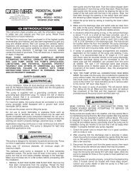
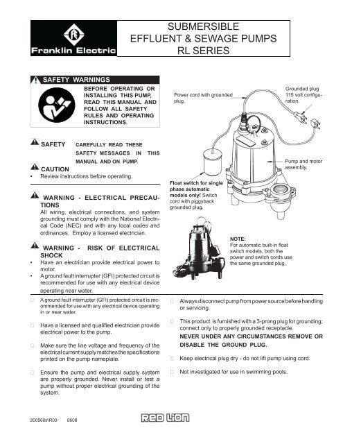
SUBMERSIBLEEFFLUENT & SEWAGE PUMPSRL SERIESSAFETY WARNINGSBEFORE OPERATING ORINSTALLING THIS PUMP,READ THIS MANUAL ANDFOLLOW ALL SAFETYRULES AND OPERATINGINSTRUCTIONS.Power cord with groundedplug,Grounded plug115 volt confi guration.SAFETY CAREFULLY READ THESESAFETY MESSAGES IN THISMANUAL AND ON PUMP.CAUTION• Review instructions before operating.WARNING - ELECTRICAL PRECAU-TIONSAll wiring, electrical connections, and systemgrounding must comply with the National ElectricalCode (NEC) and with any local codes andordinances. Employ a licensed electrician.WARNING - RISK OF ELECTRICALSHOCK• Have an electrician provide electrical power tomotor.• A ground fault interrupter (GFI) protected circuit isrecommended for use with any electrical deviceoperating near water.A ground fault interrupter (GFI) protected circuit is recommendedfor use with any electrical device operatingin or near water.Have a licensed and qualifi ed electrician provideelectrical power to the pump. Make sure the line voltage and frequency of theelectrical current supply matches the specificationsprinted on the pump nameplate.Float switch for singlephase automaticmodels only! Switchcord with piggybackgrounded plug.NOTE:For automatic built-in fl oatswitch models, both thepower and switch cords usethe same grounded plug.Pump and motorassembly.Always disconnect pump from power source before handlingor servicing.This product is furnished with a 3-prong plug for grounding;connect only to prope<strong>rl</strong>y grounded receptacle.NEVER UNDER ANY CIRCUMSTANCES REMOVE ORDISABLE THE GROUND PLUG.Keep electrical plug dry - do not lift pump using cord. Ensure the pump and electrical supply systemare prope<strong>rl</strong>y grounded. Never install or test apump without proper electrical grounding of thesystem.Not investigated for use in swimming pools.200560triR03 0608
EFFLUENT & SEWAGE APPLICATIONS - UP TO 3/4" & 2" SOLIDS HANDLING CAPABILITYThese <strong>pumps</strong> are for use in effl uent or raw <strong>sewage</strong> applicationswhere the total head required (including pipefriction losses) does not exceed the pump's maximumcapability. Sewage type <strong>pumps</strong> can be used in raw<strong>sewage</strong> or effl uent applications. Additionally, the maximum solids size, as shown inFig.1, must not be exceeded.INSTALLATION RECORDFor future reference, keep an accurate record of your installation. Be sure to record the installation data in the areaprovided below.Purchased from:Phone No. ( )Pump Model No.Pump Serial No.Date of Installation:Installation by:Phone No. ( )Pump Tank or Basin Size:Discharge Pipe size:Discharge Elevation:CapacityInchesFeetTABLE OF CONTENTSSafety, Regulatory and Electrical Warnings....................................................................................... Throughout manualApplication ............................................................................................................................................................. Page 2Installation Records and Table of Contents ........................................................................................................... Page 2Installation Information and Typical Installation Drawings ..................................................................... Pages 2, 3, 4 & 5Start Up and Operational Check............................................................................................................................ Page 6Safety Tips and Maintenance ................................................................................................................................ Page 6Troubleshooting ..................................................................................................................................................... Page 7Warranty ................................................................................................................................................................ Page 8PERFORMANCEPumpTypePumpModelSolidsHandling(inches) H.P. RPMTotal Head in Feet5 10 15 20 25Capacities in U.S. GPMEffl uent RL31ESA 11/16'' 1/3 1750 105 90 70 45 15 28Sewage RL52SA 2'' 1/2 1750 135 90 47 14 23RL52SVX 2'' 1/2 1750 112 80 40 18Shut-OffHead (ft).2
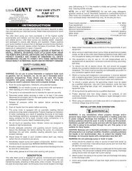
INSTALLATION1. WARNING -ELECTRICAL PRECAUTIONSBefore installation, check the national and localelectrical and plumbing codes/ordinances.... A pumpintended for use in a septic tank/sump or <strong>sewage</strong>installation requires that the tank/sump MUST BEVENTED IN ACCORDANCE WITH LOCAL PLUMB-ING CODES, and is NOT TO BE INSTALLED INLOCATIONS CLASSIFIED AS HAZARDOUS INACCORDANCE WITH THE NATIONAL ELECTRI-CAL CODE ANSI / NFPA 70-1990.These regulations are for your safety and protection.2. LOCATION:Installation of the pump must be made in a locationthat:a) Has adequate room for servicing and is of adequatesize (see page 5).b) Location is protected from freezing.c) Will require minimum lengths of piping to keepfriction losses as low as possible.d) Refer to Fig. 2 below for typical effl uent/<strong>sewage</strong>installation with automatic operation.Fig. 2TYPICAL EFFLUENT/SEWAGE SUMP INSTALLATIONAutomatic single phase 115 volt units illustratedIn FlowGround Fault Interrupter ProtectedCircuit 115 volt confi guration to matchyour pump 'Single Phase Only.' Locateminimum of 4' above fl oor level.See separate instructions for threephase models.ScumSwitch cord piggyback plug(automatic models only).Check ValveSeptic TankChamberPumpPowerCordBaffl eReliefHoleDischargeUnionTank VentTank/Basin sizeSee Table 1 on page 52" Discharge PipeSTARTSee separateinstructions withswitch for mountingand operation.The free lengthof cable mustbe at least 4" toallow free movementof the fl oat.'PumpableVolume 'START/STOP(See page 5)Must be atleast 24"3
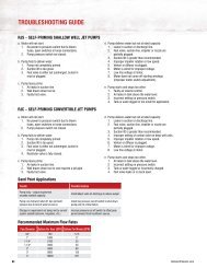
INSTALLATION3. SEPTIC TANK/SUMP PREPARATION ANDREQUIREMENTS:WARNING - ELECTRICAL PRECAUTIONSA SEPTIC SUMP CONDITION MAY EXIST. IFENTRY INTO SUMP IS NECESSARY, then fi rstprovide proper safety precautions per OSHA requirementsand secondly, DO NOT ENTER SUMP UNTILTHESE PRECAUTIONS ARE STRICTLY ADHEREDTO. Do not smoke or use sparkable electrical devicesor fl ame in a septic (gaseous) or possible septicsump. Do not install pump in location classifi ed as hazardousper National Electrical Code ANSI/NFPA 70- 1990. See Warning notes on page 3 of thismanual.a) Gas tight and prope<strong>rl</strong>y vented with national & localelectrical and plumbing codes.b) Level bottom of sump. DO NOT SET PUMP DI-RECTLY ON BOTTOM OF SUMP IF IT IS NOTSOLID. Raise the pump by using brick or concreteblocks beneath it.c) Make sure sump is clean and free of nails, gravel,string, cloth, debris, etc. before installing pump.Refer to Fig. 3 and associated Table to select a basin sizeor diameter and fl oat switch tether length that will allow asuffi cient pumpable volume to prevent short cycling.Ensure basin DEPTH is suffi cient to allow for the ON/OFFrange of the switch.Ground Fault Interrupter Protected Circuit, 115volt confi guration to match yourpump. Locate minimumof 4' above fl oor level.Pump PowerCordFig. 3TYPICAL EFFLUENT OR SEWAGETANK / BASIN INSTALLATIONAutomatic single phase 115 volt unit installationDischargeTank VentSwitch cord piggybackplug (automatic models only)Check ValveUnionTank/Basin sizeSee Table 1InletSTARTReliefHolePumpSTOPEffl uentPumpable VolumeSTART/STOP(See page 5)See separate instructions with switchfor mounting and operation. The freelength of cable must be at least 4"to allow free movement of the float.4
INSTALLATIONTABLE 1Approximate 'pumpable volume' (gallons) for variouscombinations of basin diameters and fl oat switch tethe<strong>rl</strong>engths.....Tether Length Of Float Switch (inches)Tank6 8 10 12 14 16BasinApprox. Float Switch Range (inches)Dia.(inches)10 12 16 18 22 25Pumped Volume (U.S. Gallons)18 11 13 17 20 - -24 20 23 31 35 43 4930 31 37 49 55 67 7636 44 53 70 79 97 11048 78 94 125 141 172 19560 122 147 196 220 269 30572 176 211 282 317 387 4404. PLUMBING: PUMP AND DISCHARGE PIPINGa) Use steel or plastic pipe for all connecting linesbetween pump and sewer outlet. Keep pipe lengthto a minimum to reduce friction losses. Pump isequipped with a 2" NPT female outlet - DO NOTREDUCE TO A SMALLER SIZE.NOTE: Fluid fl ow velocity in the pump's discharge linemust be at least two feet per second to carrythe effl uent without clogging. This is ensuredif pump fl ow is at least:• 21 GPM through a 2" pipe• 30 GPM through a 2-1/2" pipe• 46 GPM through a 3" pipeWARNING: Some city regulations DO NOT allowthe installation of a pump with plastic pipe. Check localregulations.b) A union or quick disconnect connection should beinstalled to facilitate pump removal if necessary. AFULL FLOW CHECK VALVE IS RECOMMENDEDAFTER THE UNION TO PREVENT BACKFLOWAFTER EACH PUMPING CYCLE.NOTE: When a check valve is used, drill a 1/8" or3/16" air relief hole in the discharge pipe.This hole should be located below the fl oo<strong>rl</strong>ine within the sealed pump unit and betweenthe pump and check valve (see Fig. 2 & 3).Without this relief hole, the pump can air lockand will not pump even though it will run.5. MOUNTING THE FLOAT SWITCH:AUTOMATIC OPERATION MODELS ONLYa) All automatic models; Single Phase 115 voltmodels come supplied with a float switch for mountingto the pump's discharge pipe and requires finaladjustment to suit your systems needs.b) The fl oat switch is equipped with a cord and 115volt grounded piggyback plug confi guration (dependingon the voltage rating of the model youhave). The switch provides automatic operationof the pump in water, effl uent and <strong>sewage</strong> applications.WARNING - RISK OF ELECTRICAL SHOCKc) The fl oat switch is packaged separately within thepump carton and includes the switch manufacturer'sassembly, adjustment, operation, safetyand cautionary instructions. Follow the manufacturer'sinstructions explicitly for properinstallation and operation. The free length ofcable must be at least 4" to allow free movementof the float.6. MANUAL MODELS:SINGLE PHASE 115 VAC MODELSa) Single Phase 115 volt manual models DO NOTINCLUDE A FLOAT SWITCH.b) The pump comes equipped with a power cord and115 volt grounded plug confi guration (dependingon the voltage rating of the model you have).c) Plug in or unplug pump power cord as needed intoground fault interrupter (GFI) protected circuit oruse with an approved motor control that matchesthe pump/motor input rated amperes. The motorcontrol must be prope<strong>rl</strong>y sized for the pump,installed and wired in compliance with the NationalElectrical Code (NEC) and any local codes andordinances.5
START UP AND OPERATIONAL CHECK7. AUTOMATIC MODELS (WITH FLOAT SWITCH)SINGLE PHASE 115 VAC MODELS:a) Connect the 3-prong grounded piggyback plug onthe fl oat switch cord into a 115 vac (depending onyour model) ground fault interrupter (GFI) receptacle.DO NOT REMOVE GROUND PRONG FROMPLUG. DO NOT USE AN EXTENSIONCORD.b) Connect the 3-prong grounded plug from thepump power cord into the piggy back receptacleon the back of switch plug. DO NOT REMOVEGROUND PRONG FROM PLUG. DO NOTUSE AN EXTENSION CORD.8. MANUAL MODELS:SINGLE PHASE 115 VAC MODELSa) Manually fi ll the tank/basin with water to check thepump's operation. DO NOT RUN DRY.b) Connect the 3-prong grounded plug on the pumppower cord into 115 VAC (depending on yourmodel) ground fault interrupter (GFI) receptacleor approved motor control. DO NOT REMOVEGROUND PRONG FROM PLUG. DO NOTUSE AN EXTENSION CORD.c) Cycle your system a few times to ensure that itsoperation is satisfactory. Replace tank/basin coverand double check to ensure that all systemcomponents/requirements are in place.c) Manually fi ll the tank/basin with water to check theswitch operation. DO NOT RUN DRY.d) Ensure that the fl oat switch hangs free and theSTART /STOP levels are satisfactory. The fl oatswitch MUST NOT COME IN CONTACT WITHSIDES OR BOTTOM OF TANK / BASIN.e) Cycle your system a few times to ensure thatits operation is satisfactory. Replace tank/basincover and double check to ensure that all systemcomponents/requirements are in place.SAFETY TIPS AND MAINTENANCE9. SAFETY TIPS WARNING:RISK OF ELECTRICAL SHOCK- BODILY INJURYa) Always wear rubber boots when you must unplugthe pump from the power supply.b) Never make adjustments or do maintenancechecks with power connected. Always disconnectyour pump from the electrical power supply beforebeginning ANY service.c) DO NOT SMOKE OR USE SPARKABLE ELEC-TRICAL DEVICES OR FLAME IN A SEPTIC(GASEOUS) SUMP.d) A SEPTIC SUMP CONDITION MAY EXIST. If entryinto sump is necessary, first provide proper safetyprecautions per OSHA requirements and secondly,DO NOT ENTER SUMP UNTIL THESE PRECAU-TIONS ARE STRICTLY ADHERED TO.e) NEVER REMOVE GROUND PRONG FROMANY POWER OR SWITCH PLUG. This is theground and is there for your safety.10. MAINTENANCE: YOUR PUMP IS CONSTRUCTEDSO THAT NO REGULAR MAINTENANCE IS REQUIREDSINCE THE PUMP IS COMPLETELY SELF LUBRICAT-ING. THE FOLLOWING ROUTINE CHECKING PRO-CEDURE IS RECOMMENDED TO BE CONDUCTEDEACH YEAR - AND ESPECIALLY IMPORTANT FOROCCASIONAL USE APPLICATIONS.a) Check power cords, switch cords and electricalservice outlets for damage and corrosion.b) Ensure there is no build up of sludge, sediment orblockage in the tank/basin to clog the pump.c) Manually raise and lower the fl oat switch to ensurecorrect pump operation (important for occasionaluse applications).d) Manually fi ll the tank/basin to check for correctswitch adjustment and system operation.6
11. TROUBLESHOOTING: FOLLOW ALL SAFETY TIPS, PROCEDURES AND WARNINGS PREVI-OUSLY IDENTIFIED IN THIS MANUAL BEFORE TROUBLESHOOTINGTHE SYSTEM.TROUBLESHOOTINGTROUBLE PROBABLE CAUSE CORRECTIVE ACTIONMotor does not run Blown fuse ReplaceTripped circuitResetDisconnected plug ReinstallCorroded plugClean prongsTripped ove<strong>rl</strong>oadAllow pump to cool, investigate cause (jammed impeller)Defective switchReplace switchDefective motorRepair pump or replace if necessaryFloat-improper position Check for freedom of movement and operating levelsMotor runs but flow reduced or none at all Impeller jammed Disassemble pump and cleanPlugged check valve Remove valve and cleanPartially blocked inlet Clean inletLine leakRepairWorn impellerRepair pump or replace if necessaryDefective motorRepair pump or replace if necessaryRuns continuously Plugged pump inlet CleanDefective switchReplace switchFloat obstructionAdjust position of pump or fl oatPlugged check valve Remove valve, clean or replaceNOTE: A plugged pump inlet can be mistaken for a faulty switch. If pump runs continuously or for extendedperiods between turn offs, check fi rst for a partially plugged pump inlet.SERVICE12. SERVICE:a) If your pump requires service it must be repaired byan authorized <strong>Red</strong> <strong>Lion</strong> service center or warrantywill be void. If a service center is not available,return your pump to the place of purchase.b) YOUR WARRANTY IS VOID IF...Pump has been used to pump hot water (above140°F).Pump has been dismantled by someone other than anauthorized service center.Power cord has been cut.Pump has been used to pump mud, cement, tar,abrasives or chemicals.7
LIMITED WARRANTYFor warranty consideration, Franklin Electric Company, Inc. and its subsidiaries (hereafter “the Company”) warrants that the products specified in this warrantyare free from defects in material or workmanship of the Company. During the time periods and subject to the terms and conditions hereinafter set forth,the Company will repair or replace to the original user or consumer any portion of this product which proves defective due to materials or workmanship of theCompany. At all times the Company shall have and possess the sole right and option to determine whether to repair or replace defective equipment, parts, orcomponents. The Company has the option to inspect any product returned under warranty to confirm that the warranty applies before repair or replacementunder warranty is approved. This warranty sets forth the Company’s sole obligation and purchaser’s exclusive remedy for defective product. Return defectiveproduct to the place of purchase for warranty consideration.WARRANTY PERIOD - PRODUCTS: 12 months from date of purchase by the user (No warranty on brushes, impeller or cam on models with brush-typemotors and/or flex-vane impellers). In the absence of suitable proof of the purchase date, the effective period of this warranty will begin on the product’sdate of manufacture.LABOR, ETC. COSTS: The Company shall IN NO EVENT be responsible or liable for the cost of field labor or other charges incurred by any customer inremoving and/or affixing any product, part or component thereof.PRODUCT IMPROVEMENTS: The Company reserves the right to change or improve its products or any portions thereof without being obligated to providesuch a change or improvement for units sold and/or shipped prior to such change or improvement.GENERAL TERMS AND CONDITIONS: This warranty shall not apply to damage due to acts of God, normal wear and tear, normal maintenance services andthe parts used in connection with such service, lightning or conditions beyond the control of the Company, nor shall it apply to products which, in the solejudgment of the Company, have been subject to negligence, abuse, accident, misapplication, tampering, alteration; nor due to improper installation, operation,maintenance or storage; nor to excess of recommended maximums as set forth in the instructions.Warranty will be VOID if any of the following conditions are found:1. Product is used for purposes other than those for which it was designed and manufactured2. Product not installed in accordance with applicable codes, ordinances, and good trade practices3. Product connected to voltage other than indicated on nameplate4. Pump exposed to but not limited to the following: sand, gravel, cement, grease, plaster, mud, tar, hydrocarbons, or hydrocarbon derivatives (oil, gasoline,solvents, etc.) or other abrasive or corrosive substances5. Pump has been used for pumping of liquids above 140°F6. Pump allowed to operate dry (fluid supply cut off)7. Sealed motor housing opened or product dismantled by customer8. Cord cut off to a length less than three feetDISCLAIMER: Any oral statements about the product made by the seller, the Company, the representatives or any other parties, do not constitute warranties,shall not be relied upon by the user, and are not part of the contract for sale. Seller’s and the Company’s only obligation, and buyer’s only remedy,shall be the replacement and/or repair by the Company of the product as described above. NEITHER SELLER NOR THE COMPANY SHALL BE LIABLE FORANY INJURY, LOSS OR DAMAGE, DIRECT, INCIDENTAL OR CONSEQUENTIAL (INCLUDING, BUT NOT LIMITED TO, INCIDENTAL OR CONSEQUENTIALDAMAGES FOR LOST PROFITS, LOST SALES, INJURY TO PERSON OR PROPERTY, OR ANY OTHER INCIDENTAL OR CONSEQUENTIAL LOSS), ARISINGOUT OF THE USE OR THE INABILITY TO USE THE PRODUCT, AND THE USER AGREES THAT NO OTHER REMEDY SHALL BE AVAILABLE TO IT. Beforeusing, the user shall determine the suitability of the product for his intended use, and user assumes all risk and liability whatsoever in connection therewith.THE WARRANTY AND REMEDY DESCRIBED IN THIS LIMITED WARRANTY IS AN EXCLUSIVE WARRANTY AND REMEDY AND IS IN LIEU OF ANY OTHERWARRANTY OR REMEDY, EXPRESSED OR IMPLIED, WHICH OTHER WARRANTIES AND REMEDIES ARE HEREBY EXPRESSLY EXCLUDED, INCLUDINGBUT NOT LIMITED TO ANY IMPLIED WARRANTY OF MERCHANTABILITY OR FITNESS FOR A PARTICULAR PURPOSE, TO THE EXTENT EITHER APPLIESTO A PRODUCT SHALL BE LIMITED IN DURATION TO THE PERIODS OF THE EXPRESSED WARRANTIES GIVEN ABOVE. Some states and countries donot allow the exclusion or limitations on how long an implied warranty lasts or the exclusion or limitation of incidental or consequential damages, so theabove exclusion or limitations may not apply to you. This warranty gives you specific legal rights, and you may also have other rights which vary from stateto state and country to country.Toll Free Help Hotline:1-800-667-1457RED LION51 Burmac Road, P.O. Box 429Winnipeg, Manitoba, CanadaR3C 3E4Phone: (877) 337-2650Fax: (204) 255-5214www.redlionproducts.com8
POMPES D'EFFLUENTS ETD'ÉGOUT SUBMERSIBLESRL SÉRIESCONSIGNES DE SÉCURITÉSÉCURITÉAVANT D'INSTALLER OUD'UTILISER CETTE POMPE,PRIÈRE DE LIRE LE PRÉSENTGUIDE ET SUIVRE TOUTESLES RÈGLES DE SÉCURITÉET INSTRUCTIONS D'UTILISATIONLIRE ATTENTIVEMENT LES AVISDE SÉCURITÉ SE TROUVANT DANSLE PRÉSENT MANUEL ET SUR LAPOMPE.MISES EN GARDE• Passez les instructions en revue avant d'utiliser lapompe.AVERTISSEMENT- PRÉCAUTIONS ÉLECTRIQUESTous câblage, connexions électriques et mise à la terre dessystémes doivent se conformer au Code National d'Electricité(NEC) et aux codes et ordonnances locaux. Employez unélectricien autorisé.AVERTISSEMENT- RISQUE DE CHOC ÉLECTRIQUE• Faire appel à un électricien pour l'alimentation électrique dumoteur.• Un interrupteur à circuit de terre protégé (GFI) est recommandépour l'utilisation de tout appareil électrique près del'eau.Cordon d'alimentation avecfi che munie d'une miseà la terre (les modèlestriphasés n'ont pas defiche).Interrupteur àflotteur pour lesmodèles automatiquesmonophasés seulement!Cordon d'interrupteur munid'un ensemble fi che-priseavec mise à la terre.NOTE:Pour les modèles munis d'uninterrupteur automatiqueintégré, la même fi che avecmise à terre s'utilise pou<strong>rl</strong>e cordon d'alimentation etcelui d'interrupteur.Fiche avecmise à la terrepour confi gurationsde 115 &230 VEnsemblepompe/moteurL’utilisation d’un circuit protégé d’interrupteur de défaut à laterre (GFI) est recommandée pour l’opération de tout appareilélectrique dans l’eau ou près de l’eau.Faites appel à un électricien agréé et compétent pour amene<strong>rl</strong>e courant électrique à la pompe.Assurez-vous que la tension de ligne et la fréquence del’alimentation en courant électrique correspondent auxcaractéristiques inscrites sur la plaque signalétique de lapompe.Débranchez toujours la pompe avant de la manipuler ou d’enfaire l’entretien.Ce produit (monophasé - unités de 115 & 230 V SEULEMENT)est muni d’une prise à trois broches dont une mise à la terre;ne branchez que dans un réceptacle avec mise à la terreconvenable. NE JAMAIS, POUR QUELQUE RAISONQUE CE SOIT, RETIRER LA MISE À LA TERRE OUMETTRE CELLE-CI HORS-FONCTION.Assurez-vous que la pompe et le système d’alimentation enélectricité sont correctement mis à la terre. Évitez d’installerou de mettre une pompe à l’essai, si le système n’est pasconvenablement mis à la terre.Gardez la fiche électrique sèche - évitez de soulever la pompepar le cordon.L'utilisation dans les piscines d'a pas été mise à l'épreuve.9
APPLICATIONS D'EFFLUENTS ET D' EAUX D'ÉGOUT - CAPACITÉ DE PASSAGE DE SOLIDESJUSQU'À 3/4 PO. ET DE 2 PO.Ces pompes sont conçues pour les applications d’<strong>effluent</strong>s oud'eaux d'égout brutes dont la hauteur totale exigée (incluantles pertes dues au frottement) ne dépasse pas la capacitémaximale des pompes. Les pompes de puisard peuvent êtreutilisées pour les applications d'effl uents ou d'eaux d'égoutbrutes.DOSSIER D’INSTALLATIONDe plus, la dimension maximale des solides, indiquée dansla fi gure 1 ci-dessous, ne doit être dépassée.À des fi ns de référence ultérieure, gardez à jour un dossier de votre installation. Assurez-vous d’inscrire les données dans l’espaceci-dessous.Acheté de :N° tél : ( )N° modèle/pompeN° série/pompeDate d’installationInstallation par :N° tél : ( )Dimension/réservoir/bassinDimension/tuyau de refoulementHauteur de refoulementCapacitéPoucesPiedsTABLE DES MATIÈRESSécurité - Réglementation - Mises en garde relatives à l’électricité ..................................................................... (dans tout le manuel)Application .................. ................................................................................................................................................................Page 2Dossiers d’installation et table des matières ...............................................................................................................................Page 2Instructions et graphiques d’installation.......................................................................................................................Pages 2, 3, 4 & 5Démarrage et vérifi cation du fonctionnement ..............................................................................................................................Page 6Conseils de sécurité et d’entretien ..............................................................................................................................................Page 7Dépannage ..........................................................................................................................................................................Pages 7 & 8Garantie .......................................................................................................................................................................................Page 8RENDEMENTPumpTypePumpModelSolidsHandling(inches) H.P. RPMTotal Head in Feet5 10 15 20 25Capacities in U.S. GPMEffl uent RL31ESA 11/16'' 1/3 1750 105 90 70 45 15 28Sewage RL52SA 2'' 1/2 1750 135 90 47 14 23RL52SVX 2'' 1/2 1750 112 80 40 18Shut-OffHead (ft).10
1. AVERTISSEMENT- PRÉCAUTIONS ÉLECTRIQUESAvant l’installation, consultez les ordonnances/codes nationauxet locaux en matière d’électricité et de plomberie.... Unepompe spécialement conçue pour utilisation dans une fosseseptique ou installation de pompage EXIGE que le réservoir/puisardSOIT MUNI D’UN DISPOSITIF D’AÉRATIONCONFORME AUX CODES DE PLOMBERIE LOCAUX,ET ELLE NE DOIT PAS ÊTRE INSTALLÉE DANS DESENDROITS CLASSIFIÉS COMME ÉTANT DANGEREUXEN VERTU DU CODE NATIONAL DE L’ÉLECTRICITÉANSI/NFPA 70-1990. Ces règlements visent à assurer votresécurité et votre protection.Interrupteur de défaut à la terre. Circuit de 115& 230 V. Configuration qui correspond à votrepompe 'monophasée seulement'. Trouvezun minimum de 4 pi. au-dessus du niveau dusol. Voir instructions séparées pour modèlestriphasés.EntréeCordond’alimentationde la pompeEnsemble fi che-prise du cordond’interrupteur (modèles automatiquesseulement).Clapet de retenueChambre de la fosse septiqueCouche fl ottanteSédimentsINSTALLATION2. EMPLACEMENT :ChicaneLa pompe doit être installée dans un endroit...a) D’une dimension convenable, où il y a suffi sammentd’espace pour effectuer les travaux d’entretien (voirpage 5).b) Protégé contre le gel.c) Nécessitant des longueurs minimales de tuyauterie pourminimiser les pertes dues au frottement.d) Voir figure 2 ci-dessous pour l’installation de pompesd’effl uents/eaux d'égout brutes conventionnelles àfonctionnement automatique.Fig. 2INSTALLATION DE POMPES D'EFFLUENTS/EAUX D'ÉGOUT BRUTES CONVENTIONELLESMonophasée automatique. Unités de 115 & 230 V. Voir illustrationTrou dedégagementRefoulementÉvent du réservoirRaccordDimension duréservoir/bassin.Voir tableau 1/ page5Tuyau derefoulementde 2 poSTARTARRÊTVoir instructionsséparées avecinterrupteur pourmontage etfonctionnement.Le montant decablage entre laflotte et le serrecâbledoit êtreun minimum de4" pour ne pasimpêcher le movementde la flotte.'Volumepompable'MARCHE/ARRÊT(Voir page 5)Doitmesurerau moins24 po3. FOSSE SEPTIQUE/PRÉPARATION DU PU-ISARD / EXIGENCES :AVERTISSEMENT- PRÉCAUTIONS ÉLECTRIQUESLA NÉCESSITÉ D’ENTRER DANS UN PUISARD PEUTS’AVÉRER PROBLÉMATIQUE. Vous devez d’abord fournirdes consignes de sécurité qui répondent aux exigences del’OSHA, puis ÉVITER D’ENTRER DANS UN PUISARDSANS VOUS ÊTRE RIGOUREUSEMENT CONFORMÉÀ CES CONSIGNES.11Évitez de fumer ou d'utiliser des appareils électriquessusceptibles de produire des étincelles ou une fl ammedans un puisard pouvant dégager des émanations degaz.Évitez d'installer une pompe dans un endroit classifi ecomme etant dangereux en vertu du code national del'electricite ANSI/NFPA 70-1990. Voir les notes relativesa la mise en garde a la page 3 du presentmanuel.a) Étanche au gaz et muni d’un évent conforme aux codesnationaux et locaux d’électricité et de plomberie.
INSTALLATIONb) Mettre le fond du puisard à niveau. NE PAS INSTALLERLA POMPE DIRECTEMENT AU FOND DU PUISARD SICELUI-CI N’EST PAS SOLIDE. Soulever la pompe avecdes blocs de brique ou de ciment.c) S’assurer que le puisard est propre et libre de clous, gravier,corde, linges, débris, avant d’installer la pompe.Voir fi g. 3 et le tableau associà pour choisir la dimension ou lediamètre du bassin et la longueur du cordon de l’interrupteur à fl otteurqui permettront un 'volume pompable' suffisant pour empêche<strong>rl</strong>es cycles courts. S’assurer que le bassin est assez passPROFOND pour admettre la distance de la course entre la positionMARCHE/ARRÊT de l’interrupteur.Fig. 3INSTALLATION D'UN RÉSERVOIR OU BASSIN D'EFFLUENTS / EAUX D'ÉGOUT BRUTES CONVENTIONNELInstallation d'une unité monophasé automatique de 115 ou 230 VInterrupteur de défaut à la terre. Circuitde 115 & 230 V.Confi guration qui correspondà votre pompe 'monophasée seulement'. Trouvez un minimumde 4 pi. au-dussus du niveau du sol.Voir instructions séparées pour modèles triphasés.Cordon d’alimentationde la pompeRefoulementÉvent du réservoirEnsemble fi che-prisedu cordon de l’interrupteur(modèles automatiquesseulement)Clapet de retenueRaccordDimension réservoir/bassinVoir tableau 1EntréeMARCHETrou dedégagementPompeARRÊTEffl uentVolume pompableMARCHE/ARRÊT(Voir page 5)Voir instructions séparéesavec interrupteur pour montage etfonctionnementLe montant de cablage entre la flotte et le serre-câble doit êtreun minimum de 4" pour ne pas impêcher le movement de laflotte.12
INSTALLATIONTABLEAU 1'Volume pompable' approximatif (gallons) pour diverse combinaisonsde diamètres de bassins et de longueurs de cordonsd'interrupteurs à fl otteur...DiamètreRéservoirLONGUEUR DU CORDON DEL'INTERRUPTEUR À FLOTTEUR [pouces]6 8 10 12 14 16Portée approx. de l’interrupteur [pouces]10 12 16 18 22 25Débit [en gallons US]18 11 13 17 20 - -24 20 23 31 35 43 4930 31 37 49 55 67 7636 44 53 70 79 97 11048 78 94 125 141 172 19560 122 147 196 220 269 30572 176 211 282 317 387 4404. PLOMBERIE :POMPE ET TUYAUTERIE DE REFOULEMENTa) Utiliser un tuyau d’acier ou de plastique pour toutes leslignes de raccord entre la pompe et le point de rejet del’égout. Gardez une longueur minimale de tuyau pourréduire les pertes dues au frottement. La pompe estéquipée d’un orifi ce taraudé de 2 po NPT - NE PASRÉDUIRE À UNE DIMENSION MOINDRE.REMARQUE :La vitesse d’écoulement dans la conduite de refoulementde la pompe doit être au moins de 2 pieds par secondepour entraîner l’effl uent sans colmatage. Pour ce faire,le débit de la pompe doit être au moins :• 21 gpm dans un tuyau de 2 po• 30 gpm dans un tuyau de 2 ½ po• 46 gpm dans un tuyau de 3 poAVERTISSEMENT : Dans certaines villes les règlementsne permettent pas l’installation d’une pompe avectuyauterie en plastique. Vérifiez les règlements locaux.b) Un raccord ou une connexion à démontage rapide devraientêtre installés pour faciliter l’enlèvement de la pompesi nécessaire. ON RECOMMANDE D’INSTALLER UNCLAPET DE RETENUE À GRAND DÉBIT À LA SUITEDU RACCORD POUR EMPÊCHER UN REFOULE-MENT APRÈS CHAQUE CYCLE DE POMPAGE.REMARQUE :Si vous utilisez un clapet de retenue, percez un trou dedégagement d’air de 1/8 po ou de 3/16 po dans le tuyaude refoulement. Ce trou devrait se trouver sous la lignede plancher à l’intérieur de l’unité de pompe étanche etentre la pompe et le clapet de retenue (voir fi g. 2 & 3).Sans ce trou de dégagement, la pompe peut créer unepoche d’air et ne pompera pas, même si elle continueà fonctionner.5. MONTAGE DE L’INTERRUPTEUR À FLOT-TEUR: POUR LES MODÈLES À FONCTION-NEMENT AUTOMATIQUE SEULEMENTa) Tous les modèles automatiques; les modèlesmonophasés de 115 et 230 V sont munis d’un interrupteurà fl otteur devant être raccordé au tuyau de refoulementde la pompe et ils nécessitent un réglage défi nitif quiconvient à votre système.b) L’interrupteur à fl otteur est équipé d’un cordon et d’uneconfiguration de 115 ou 230 V avec ensemble fiche-prisedont une mise à la terre (selon la capacité en voltagedu modèle que vous possédez). L’interrupteur permetle fonctionnement automatique de la pompe dans l’eauet dans les applications d’effl uents et eaux d’égout.AVERTISSEMENT- RISQUE DE CHOC ÉLECTRIQUEc) L’interrupteur à fl otteur est dans un emballage séparéà l’intérieur du carton de la pompe, et il comprend desinstructions relatives à l’assemblage de l’interrupteur,le réglage, le fonctionnement et les consignes desécurité...Suivez explicitement les instructionsdu fabricant pour obtenir une installation et unfonctionnement satisfaisants. Le montant decablage entre la flotte et le serre-câble doitêtre un minimum de 4" pour ne pas impêche<strong>rl</strong>e movement de la flotte.6. MODÈLES MANUELS :MODÈLES MONOPHASÉS DE 115 ET 230VCAa) Les modèles manuels monophasés de 115 ou 230V N’INCLUENT PAS L’INTERRUPTEUR À FLOT-TEUR.13
) La pompe est équipée d’un cordon d’alimentation etd’une fiche avec mise à la terre de 115 ou 230 V (selon lacapacité en voltage du modèle que vous possédez).c) Branchez le cordon d’alimentation de la pompe dans lecircuit protégé de l’interrupteur de défaut à la terre ouutilisez-le avec une commande de moteur approuvéequi correspond à l’intensité du courant de la pompe/dumoteur. La commande de moteur doit avoir une capacitéqui convient à la pompe et être installée et câbléeconformément au code national de l’électricité (NEC)et autres ordonnances ou codes locaux.7. MODÈLES MANUELS :MODÈLES TRIPHASÉS DE 230, 460 ET 575VCAa) Les modèles triphasés de 230, 460 et 575 V N’INCLUENTPAS L’INTERRUPTEUR À FLOTTEUR.b) La pompe est équipée d’un cordon d’alimentationtriphasé sans fiche pour utilisation avec une commandede moteur approuvée qui correspond à l’intensité ducourant de la pompe/du moteur et un disjoncteur desurcharge choisi ou adapté conformément aux instructionsdu fabricant.c) La commande du moteur triphasé doit avoir une capacitéqui convient à la pompe et être installée et câbléeconformément au code national de l’électricité (NEC)et autres ordonnances ou codes locaux.DÉMARRAGE ET VÉRIFICATION DU FONCTIONNEMENT8. MODÈLES AUTOMATIQUES (AVEC IN-TERRUPTEUR À FLOTTEUR) MODÈLESMONOPHASÉS DE 115 ET 230 VCA :9. MODÈLES MANUELS :MODÈLES MONOPHASÉS DE 115 ET 230VCAa) Branchez la fi che à trois broches ( dont une miseà la terre) du cordon de l’interrupteur à fl otteur dans leréceptacle d’interrupteur de défaut à la terre (GFI) de 115ou 230 VCA (selon le modèle que vous possédez).NE RETIREZ PAS LE CONTACT DE MISE À LATERRE DE LA FICHE. N’UTILISEZ PAS DE RAL-LONGE ÉLECTRIQUE.b) Branchez la fi che à trois broches ( dont une mise à laterre) du cordon d’alimentation de la pompe dans leréceptacle fi che-prise se trouvant à l’arrière de la fi chede l’interrupteur. NE RETIREZ PAS LE CONTACTDE MISE À LA TERRE DE LA FICHE. N’UTILISEZPAS DE RALLONGE ÉLECTRIQUE.c) Remplissez d’eau le réservoir/bassin manuellementpour vérifi er le fonctionnement de l’interrupteur. NEPAS FAIRE FONCTIONNER À SEC.d) Assurez-vous que l’interrupteur est libre de tout mouvementet que les niveaux marche/arrêt sont satisfaisants.L’interrupteur à flotteur NE DOIT PAS TOUCHERLES PAROIS OU LE FOND DU RÉSERVOIR /BASSIN.e) Faites effectuer quelques cycles à votre système pourvous assurer qu’il fonctionne de façon satisfaisante.Replacez le couvercle du réservoir/bassin et contrevérifiez pour vous assurer que tous les composantsdu système sont bien en place et qu’ils répondent auxexigences.14a) Remplissez d’eau le réservoir/bassin manuellementpour vérifi er le fonctionnement de la pompe. NE PASFAIRE FONCTIONNER À SEC.b) Branchez la fiche à trois broches (dont une mise à la terre)du cordon d’alimentation de la pompe dans le réceptacled’interrupteur de défaut à la terre (GFI) de 115 ou 230VCA ou dans la commande de moteur approuvée (selonle modèle que vous possédez). NE RETIREZ PAS LECONTACT DE MISE À LA TERRE DE LA FICHE.N’UTILISEZ PAS DE RALLONGE ÉLECTRIQUE.c) Faites effectuer quelques cycles à votre système pourvous assurer qu’il fonctionne de façon satisfaisante. Replacezle couvercle du réservoir/bassin et contre-vérifiezpour vous assurer que tous les composants du systèmesont bien en place et qu’ils répondent aux exigences.10. MODÈLES MANUELS:MODÈLES TRIPHASÉS DE 230, 460 ET 575VCAa) Remplissez d’eau le réservoir/bassin manuellement pourvérifi er le fonctionnement de la pompe (selon le modèleque vous possédez). NE PAS FAIRE FONCTIONNERÀ SEC.b) Après avoir connecté le cordon d’alimentation de lapompe à une commande de moteur triphasée et approuvée,de calibre adéquat et correctement mise à laterre, faites effectuer quelques cycles à votre systèmepour vous assurer qu’il fonctionne de façon satisfaisante.Replacez le couvercle du réservoir/bassin et contrevérifiez pour vous assurer que tous les composantsdu système sont bien en place et qu’ils répondent auxexigences.
CONSEILS DE SÉCURITÉ ET ENTRETIEN11. CONSEILS DE SÉCURITÉAVERTISSEMENT :RISQUE DE CHOC ÉLECTRIQUE- BLESSURES CORPORELLESa) Portez toujours des bottes de caoutchouc quand vous devezdébrancher la pompe de sa source d’alimentation.b) Ne faites jamais de réglages ou de vérifi cations demaintenance lorsqu’il y a du courant. Débranchez toujoursvotre pompe de sa source d’alimentation avantd’entreprendre TOUT travail d’entretien.c) ÉVITEZ DE FUMER OU D’UTILISER DES APPAREILSÉLECTRIQUES SUSCEPTIBLES DE PRODUIRE DESÉTINCELLES OU UNE FLAMME DANS UN PUISARDPOUVANT DÉGAGER DES ÉMANATIONS DE GAZ.d) LA NÉCESSITÉ D’ENTRER DANS UN PUISARD PEUTS’AVÉRER PROBLÉMATIQUE. Vous devez d’abordfournir des consignes de sécurité qui répondent auxexigences de l’OSHA, puis ÉVITER D’ENTRER DANSUN PUISARD SANS VOUS ÊTRE RIGOUREUSE-MENT CONFORMÉ À CES CONSIGNES.e) NE RETIREZ JAMAIS LE CONTACT DE MISE ÀLA TERRE D’UNE FICHE D’ALIMENTATION OUD’UN COMMUTATEUR À FICHE. Il s’agit de la miseà la terre et elle y est pour votre protection.12. ENTRETIEN : VOTRE POMPE NE NÉCESSITE AUCUNENTRETIEN RÉGULIER ÉTANT DONNÉ QU’ELLE ESTCOMPLÈTEMENT AUTO-LUBRIFIANTE. ON RECOM-MANDE D’EFFECTUER LES VÉRIFICATIONS PÉRI-ODIQUES SUIVANTES UNE FOIS L’AN - SURTOUT DANSLES CAS D’UTILISATION OCCASIONNELLE.a) Vérifi ez si les cordons d’alimentation, les cordonsd’interrupteurs et les prises de courant sont endommagésou corrodés.b) Assurez-vous que la pompe n’est pas bloquée en raisond’une accumulation de sédiments boueux dans leréservoir/bassin.c) Levez et baissez manuellement l’interrupteur à fl otteurpour vous assurer que la pompe fonctionne correctement(important dans les cas d’utilisation occasionnelle)d) Remplir le réservoir/bassin manuellement pour vérifi e<strong>rl</strong>’exactitude du réglage de l’interrupteur et le bon fonctionnementdu système.DÉPANNAGE13. DÉPANNAGE: SUIVRE LES CONSEILS DE SÉCURITÉ, LES PROCÉDURES ET LES MISES EN GARDEDÉCRITES DANS LE PRÉSENT GUIDE AVANT DE DIAGNOSTIQUER LA PANNEPROBLÈME CAUSE PROBABLE SOLUTIONLe moteur ne Fusible sautéRemplacerfonctionne pas Circuit d’enclenchementRéamorcerFiche débranchéeRéinstallerFiche corrodéeNettoyer les brochesDisjoncteur de surchargeLaisser refroidir la pompe, chercher la cause (roue de turbine bloquée)Interrupteur défectueuxRemplacer l’interrupteurMoteur défectueuxRemplacer ou réparer la pompePosition incorrecte du fl otteurVérifi er la liberté de mouvement et les niveaux de fonctionnementLe moteur Roue de turbine bloquéeDémonter et nettoyer la pompetourne mais Clapet de retenue colmatéRetirer et nettoyer le clapetle débit est Orifi ce d’aspiration partiellement bloqué Nettoyer l’orifi ce d’aspirationmoindre ouConduit fuyantRéparerinexistantRoue de turbine uséeRéparer ou remplacer la pompeMoteur défectueuxRéparer ou remplacer la pompeLe moteur tourne sans Orifi ce d’aspiration bloqué NettoyerarrêtInterrupteur défectueuxRemplacer l’interrupteurFlotteur obstruéRégler la position de la pompe ou de l’interrupteurClapet de retenue colmaté Retirer, nettoyer ou remplacer le clapetLa pompe fonctionne mais Il se peut que la pompe fonctionne MISE EN GARDE : S’assurer que la source d’alimentationle débit d’eau et la pressiondans le mauvais sens. La rotation est débranchée - EN POSITION ARRÊT correcte de la rouesont plus faibles que anti-horaire quand on regarde de turbine est - et inverser deux des FILS CONDUCTEURS àd’habitude. (unités triphaséesl’orifi ce d’aspiration dans le fond l’intérieur de la commande de moteur triphasée.seulement)de la pompe.REMARQUE : On peut facilement se tromper et penser que l’orifi ce d’aspiration de la pompe est bloqué, alors que c’est l’interrupteurqui est défectueux. Si la pompe fonctionne sans arrêt, ou qu’il s’écoule de longues périodes entre les arrêts cycliques, vérifi er d’abordsi l’orifi ce d’aspiration de la pompe est partiellement colmaté.15
14. SERVICE:a) Si votre pompe nécessite une réparation, adressez-vousà un centre de service MONARCH autorisé, sinon votre garantiesera nulle. S’il n’y a pas de centre de service près de chez vous,retournez votre pompe à l’endroit où vous l’avez achetée.b) VOTRE GARANTIE EST NULLE SI... Le cordon d’alimentation a été coupé.SERVICE La pompe a été utilisée pour pomper de la boue,du ciment, du goudron des matières abrasives ouchimiques. La pompe a été utilisée pour pomper de l’eau chaude(au-dessus de 140° F). La pompe a été démontée par un réparateur autre qu’uncentre de service autorisé.GARANTIE LIMITÉELors des requêtes en garantie, Franklin Electric Company, Inc. et ses filiales (ci-après appelée « l’Entreprise ») garantit les produits spécifiés dans cette garantiecontre tout défaut de matériaux et de main-d’œuvre. Pendant les périodes couvertes par la garantie et selon les conditions indiquées dans la présente,l’Entreprise réparera ou remplacera toute partie de ce produit présentant une défaillance liée aux matériaux ou à la main-d’œuvre, et ce uniquement auprèsdu premier utilisateur ou acheteur. En tout temps, l’Entreprise conserve le droit et l’option de déterminer si un équipement, des pièces ou des composantsdéfectueux doivent être réparés ou remplacés. L’Entreprise peut inspecter tout produit sous garantie qui lui est retourné afin de confirmer que la garanties’applique, avant d’approuver la réparation ou le remplacement. Cette garantie stipule l’unique obligation de l’Entreprise et le recours exclusif de l’acheteurpour un produit défectueux. Retourner le produit défectueux au détaillant pour les requêtes en garantie.PÉRIODE DE GARANTIE – PRODUITS : 12 mois à partir de la date d’achat par l’utilisateur. (Aucune garantie n’est offerte pour les balais, le rotor ou la camesur les modèles avec moteur à balais et/ou rotor flexible à palettes.) En l’absence d’une preuve adéquate de la date d’achat, la période d’application commenceraà partir de la date de fabrication.COÛTS DE MAIN-D’ŒUVRE, ETC. : EN AUCUN CAS l’Entreprise ne pourra être tenue responsable du coût de la main-d’œuvre ou d’autres frais encouruspar un client lors de la dépose et/ou de la réparation d’un produit, d’une partie ou d’un composant.AMÉLIORATIONS DU PRODUIT : L’Entreprise se réserve le droit de modifier ou d’améliorer ses produits, ou une quelconque de leur partie, sans obligationde fournir une telle modification ou amélioration aux appareils déjà vendus et/ou expédiés avant que de telles modifications ou améliorations n’aient étéapportées.CONDITIONS ET MODALITÉS GÉNÉRALES : Cette garantie ne couvre pas les dommages causés par une catastrophe naturelle, l’usure normale, la foudreou des conditions hors du contrôle de l’Entreprise; et elle ne couvre pas non plus les services d’entretien normaux et aux pièces usées associés à un telservice, ni les produits qui, selon le jugement exclusif de l’Entreprise, ont été exposés à la négligence, l’abus, un accident, une application inappropriée,une altération, une modification; ni aux dommages causés par une installation, une utilisation, un entretien ou un entreposage inadéquat; ni à une utilisationau-delà des maximums recommandés, comme il est indiqué dans les instructions.La garantie est NULLE si l’une des conditions suivantes s’applique :1. Le produit est utilisé pour des applications autres que celles pour lesquelles il a été conçu et fabriqué.2. Le produit n’est pas installé dans le respect des codes et règlements applicables et selon les bonnes pratiques acceptées dans l’industrie.3. Le produit a été branché à une tension autre que celle indiquée sur la plaque signalétique.4. La pompe a été exposée, entre autres, aux produits suivants : sable, gravier, ciment, graisse, plâtre, boue, goudron, hydrocarbures, dérivésd’hydrocarbure (huile, essence, solvants, etc.) ou autres substances abrasives ou corrosives.5. La pompe a été utilisée pour pomper des liquides dépassant 60 °C (140 °F).6. La pompe a fonctionné à sec (alimentation en liquide coupée).7. Le carter moteur scellé a été ouvert ou le produit a été démonté par le client.8. Le cordon a été coupé à une longueur inférieure à 0,9 m (3 pieds).AVIS DE NON-RESPONSABILITÉ : Toute déclaration verbale portant sur le produit, faite par le vendeur, l’Entreprise, les représentants ou toute autre partiene constitue pas une garantie et ne peut être considérée par l’utilisateur comme faisant partie du contrat de vente. La seule obligation du vendeur ou del’Entreprise et le seul recours de l’acheteur est le remplacement et/ou la réparation du produit par l’Entreprise, comme il est décrit ci-dessus. LE VENDEUROU L’ENTREPRISE NE PEUT ÊTRE TENU RESPONSABLE POUR TOUTE BLESSURE, PERTE OU DOMMAGE DIRECT, INDIRECT OU CONSÉCUTIF(INCLUANT MAIS SANS S’Y LIMITER LES DOMMAGES INDIRECTS OU CONSÉCUTIFS LIÉS À UNE PERTE DE PROFITS, UNE PERTE DE VENTES,DES BLESSURES OU DES DOMMAGES MATÉRIELS, OU TOUT AUTRE INCIDENT OU PERTE CONSÉCUTIVE), RÉSULTANT DE L’UTILISATION OU DEL’IMPOSSIBILITÉ D’UTILISER LE PRODUIT; DE PLUS, L’UTILISATEUR ACCEPTE QU’AUCUN AUTRE RECOURS N’EST DISPONIBLE. Avant de commencerà utiliser le produit, l’utilisateur doit déterminer si ce produit est adapté à l’usage prévu; et l’utilisateur assume tous les risques et toutes les responsabilitésqui sont liés à cette utilisation. LA GARANTIE ET LES MESURES CORRECTIVES DÉCRITES DANS LA PRÉSENTE GARANTIE LIMITÉE CONSTITUENT UNEGARANTIE ET DES MESURES CORRECTIVES EXCLUSIVES EN LIEU ET PLACE DE TOUTE AUTRE GARANTIE ET MESURE CORRECTIVE, EXPRESSEOU IMPLICITE; ET TOUTE AUTRE GARANTIE ET MESURE CORRECTIVE EST EXPRESSÉMENT EXCLUE, INCLUANT, MAIS SANS S’Y LIMITER, TOUTEGARANTIE IMPLICITE DE QUALITÉ MARCHANDE OU D’ADAPTATION À UN USAGE PARTICULIER. Certaines juridictions et certains pays interdisent lesexclusions ou les limitations de durée d’une garantie implicite ou l’exclusion ou la limitation des dommages indirects ou consécutifs; les limitations ou exclusionsci-dessus pourraient donc ne pas s’appliquer à votre cas. Cette garantie vous donne des droits légaux spécifiques et vous pourriez également jouird’autres droits qui varient selon la juridiction ou le pays.SERVICE A LA CLIENTELE:Ligne directe à 1-800-667-1457RED LION51 Burmac Road, P.O. Box 429Winnipeg, Manitoba, CanadaR3C 3E4Fax: (204) 255-5214www.redlionproducts.com16
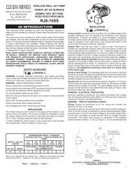
BOMBAS SUMERGIBLES PARASÓLIDOS Y AGUAS NEGRASRL SERIESADVERTENCIAS DE SEGURIDADLEA ESTE MANUAL YSIGA TODAS LAS NORMASDE SEGURIDAD ANTES DEINSTALAR U OPERAR ESTABOMBA.Cable eléctrico con enchufede contacto a tierra (losmodelos trifásicos notienen enchufe).Enchufe concontacto atierra paraconfi guracionesde 115y 230 voltios.SEGURIDADCUIDADOLEA CUIDADOSAMENTE ESTOS MEN-SAJES DE SEGURIDAD EN ESTEMANUAL Y EN LA BOMBA.• Revise cuidadosamente las instrucciones antes de usa<strong>rl</strong>a.Ensamblajede bomba ymotor.AVISO - PRECAUCIONES ELÉCTRICASTodo cableado, conexiones eléctricas y sistemas de contacto atierra deben cumplir con el Código Eléctrico Nacional (NEC) ycon cualquier código y ordenanza local. Contrate los serviciosde un electricista con licencia.AVISO - RIESGO DE DESCARGA ELÉCTRI-CA• Haga que un electricista conecte la electricidad al motor.• Se recomienda se use un circuito protegidopor un Interruptor con Falla a Tierra (GFI)Interruptor deflotador para losmodelos automáticos monofásicossolamente! Cable de interruptorcon enchufe incorporado concontacto a tierra.NOTA:Para los modelos con el interruptorfl otador integrado, se utilisa elmismo cable eléctrico con enchufede contacto por el cable de energíaeléctrica y él de interruptor.Se recomienda se use un circuito protegido con interruptorde contacto a tierra (GFI) con todo dispositivo eléctrico queopere en o cerca del agua.Este producto (Unidades Monofásicas - 115 y 230 voltiosSOLAMENTE) está provisto de un enchufe con tres clavijaspara hacer contacto a tierra, conéctelo solamente a unHaga que un electricista conecte la electricidad a la bomba.tomacorriente debidamente conectado a tierra. NUNCA,BAJO NINGUNA CIRCUNSTANCIA, QUITE NI ANULEAsegúrese que el voltaje y la frecuencia de la corrienteeléctrica concuerden con las especifi caciones impresas enla plancha de marca de la bombaAsegúrese que la bomba y el sistema de abastecimientoeléctrico estén debidamente conectados a tierra. Nuncainstale ni pruebe una bomba sin el debido contacto a tierradel sistema.EL ENCHUFE DE CONTACTO A TIERRA.Mantenga el enchufe seco, no levante la bomba usando elcable.No se ha investigado su uso para el área de piscinas.Desconecte siempre el enchufe de la fuente de poder antesde manipula<strong>rl</strong>a.17
APLICACIÓN PARA EFLUENTES Y DESAGÜES - CAPACIDAD PARA SÓLIDOS HASTA 3/4 PULGA-DAS Y 2 PULGADASEstas bombas son para usarse en aplicaciones para efluenteso desagüe sin tratar donde la presión total requerida (incluyendolas pérdidas por fricción) no excedan la capacidad dela bomba. Las bombas del tipo para desagües se puedenusar en aplicaciones efl uentes o desagüe sin tratar.Además, no se debe exceder el tamaño máximo de lossólidos . Vea la Fig.1.REGISTRO DE INSTALACIÓNGuarde un registro exacto de su instalación para referencias futuras. Asegúrese de registrar la información de la instalación en elárea proporcionada enseguida.Comprada de:Número telefónico: ( )Bomba modelo No.Bomba serie No.Fecha de instalación:Instalada por:Número telefónico: ( )Tamaño del tanque o letrina:Tamaño de descarga de la tubería:Elevación de la descarga:CapacidadPulgadasPiesTABLA DE CONTENIDOAdvertencias de seguridad, regulatorias y eléctricas ................................................................................................En todo el manualAplicaciones .............................................................................................................................................................................Página 2Registros de instalación y tabla de contenido ..........................................................................................................................Página 2Información de instalación y dibujos de instalación típica ........................................................................................ Páginas 2, 3, 4 y 5Revisión de encendido y funcionamiento .................................................................................................................................Página 6Pautas de seguridad y mantenimiento .....................................................................................................................................Página 7Cómo resolver problemas ................................................................................................................................................ Páginas 7 y 8Garantía....................................................................................................................................................................................Página 8RENDIMIENTOPumpTypePumpModelSolidsHandling(inches) H.P. RPMTotal Head in Feet5 10 15 20 25Capacities in U.S. GPMEffl uent RL31ESA 11/16'' 1/3 1750 105 90 70 45 15 28Sewage RL52SA 2'' 1/2 1750 135 90 47 14 23RL52SVX 2'' 1/2 1750 112 80 40 18Shut-OffHead (ft).18
INSTALACIÓN1. AVERTENCIA- PRECAUCIONES ELÉCTRICASAntes de instala<strong>rl</strong>a, revise los códigos eléctricos y deplomería nacionales y locales. Una bomba hecha parausarse en aplicaciones de tanques sépticos o letrinasREQUIERE que el tanque o letrina ESTÉ VENTILADODE ACUERDO A LOS CÓDIGOS LOCALES DEPLOMERÍA, y NO SE DEBE INSTALAR EN ÁREASCLASIFICADAS COMO PELIGROSAS DE ACUERDOAL CÓDIGO ELÉCTRICO NACIONAL ANSI/NFPA 70-1990. “Estas regulaciones son por su propia seguridad yprotección”.2. UBICACIÓN:La bomba debe estar ubicada en un lugar que:a) Tenga sufi ciente espacio para da<strong>rl</strong>e mantenimiento yque sea del tamaño adecuado “vea la página 5”.b) Esté protegido contra temperaturas congelantes.c) Necesite lo mínimo de tubería para mantener las pérdidaspor fricción al mínimo.d) Vea en la Fig. #2 a continuación la instalación típica paraefl uentes/desagües con funcionamiento automático.Fig. 2INSTALACIÓN TÍPICA PARA LETRINA DE EFLUENTES/DESAGÜESUnidades ilustradas: monofásicas automáticas de 115 o 230 voltiosConfiguración de circuito con Interruptor Automáticopor Contacto a Tierra de 115 y 230 voltios paraconcordar con su bomba “Monofásica Solamente”Colóquelo a por lo menos 4 pies del nivel delfondo. “Vea las instrucciones por separado paralos modelos trifásicos”.Flujo de entradaEspumaCable del interruptor conenchufe a cuestas (modelosautomáticos solamente)Válvula de chequeoCámara del tanque sépticoCable eléctricode la bombaDefl ectorAgujero de desfogueDescargaRespiradero del tanqueUniónTamaño del tanque/letrina. Vea la tabla1 en la página 5.Tubería dedescarga de2 pulgadasEncendidoApagueVea en lasinstrucciones por separadola instalacióny funcionamiento delinterruptor.La Parte del cableentre el interruptory la abrazadera nodebe sur menos de4" para que el mevimieatodep flotadorsea libre.“Volumenbombeable”Encendido/Apague,vea la pág. 5Debe estara por lomenos 24pulgadasSedimento3. PREPARACIÓN Y REQUERIMIENTOS DELTANQUE SÉPTICO / LETRINAAVERTENCIA- PRECAUCIONES ELÉCTRICASPUEDE HABER UNA CONDICIÓN DE LETRINA SÉPTICA.SI LA ENTRADA A LA LETRINA FUERA NECESARIA,proporcione primero las debidas precauciones de seguridadde acuerdo a los requerimientos de OSHA, y segundo, NO19ENTRE EN LA LETRINA HASTA QUE SE SIGAN ES-TRICTAMENTE ESTAS PRECAUCIONES. No fume ni use dispositivos eléctricos que generen chispasne llamas en una posible letrina séptica (gaseosa). No instale la bomba en un àrea clasificada como peligrosa deacuerdo al código eléctrico nacional ANSI/NFPA 70-1990. Vealas notas de advertencia en la pàgina 2 de este manual.a) Hermética de gas y debidamente ventilada de acuerdo a loscódigos eléctricos nacionales y locales.
) Fondo nivelado de la letrina. NO INSTALE LA BOMBADIRECTAMENTE SOBRE EL FONDO DE LA LETRINASI ÉSTA NO ES SÓLIDA. Eleve la bomba colocandobloques de ladrillo o concreto debajo de la misma. c)Asegúrese que la letrina esté limpia y sin clavos, grava, hilos,telas, ropas, desperdicios, etc. antes de instala<strong>rl</strong>a.INSTALACIÓNVea la Fig. #3 y la tabla correspondiente a continuaciónpara seleccionar el tamaño o diámetro de la letrina y ellargo del cable del interruptor de fl otador que permita un“volumen bombeable” sufi ciente para evitar el corto ciclaje.Asegúrese que la PROFUNDIDAD de la letrina sea suficiente parapermitir el rango de ENCENDIDO/APAGUE del interruptor.Fig. 3INSTALACIÓN TÍPICA DE TANQUE/LETRINA PARA EFLUENTES O DESAGÜESInstalación de unidad monofásica automática de 115 o 230 voltiosConfi guración de circuito con InterruptorAutomático por Contacto a Tierra de 115 y230 voltios para concordar con su bomba“Monofásica Solamente” Colóquelo a po<strong>rl</strong>o menos 4 pies del nivel del fondo. “Vea lasinstrucciones por separado para los modelostrifásicos”.Cable eléctricode la bombaCable del interruptorcon enchufe a cuestas(modelos automáticossolamente)Válvula de chequeoDescargaRespiradero del tanqueUniónTamaño del tanque/letrina.Vea la tabla 1EntradaEncendidoAgujero dedesfogueApagueBombaVolumen bombeableEncendido/Apague(vea la pág. 5)Efl uenteVea en las instrucciones porseparado la instalación y funcionamientodel interruptor.La Parte del cable entre el interruptor y la abrazadera no debe surmenos de 4" para que el mevi-mieato dep flotador sea libre.20
INSTALACIÓNTABLA 1“Volumen bombeable” aproximado (galones) para variascombinaciones de diámetros de letrinas y largos decable de interruptores de fl otador…LARGO DEL CABLE DEL INTERRUPTORDiàmetroDE FLOTADOR (pulgadas)6 8 10 12 14 16deltanque/ Escala aprox. del interruptor (pulgadas)letrina 10 12 16 18 22 25Cantidad (en galones US)18 11 13 17 20 - -24 20 23 31 35 43 4930 31 37 49 55 67 7636 44 53 70 79 97 11048 78 94 125 141 172 19560 122 147 196 220 269 30572 176 211 282 317 387 4404. PLOMERÍA:TUBERÍAS DE BOMBEO Y DESCARGAa) Utilice tuberías de acero o de plástico para todas lasconexiones entre la bomba y la salida del desagüe.Mantenga el largo de la tubería al mínimo para reduci<strong>rl</strong>as pérdidas por fricción. La bomba está equipada conuna toma de salida de 2 pulgadas NPT. NO REDUZCAA UN TAMAÑO MENOR.NOTA:La velocidad de fl ujo de los líquidos en la líneade descarga de la bomba debe ser de por lomenos dos pies por segundo para llevar elafl uente sin atorarse. Esto se logra si el fl ujode la bomba es de por lo menos:• 21 gpm por una tubería de 2 pulgadas• 30 gpm por una tubería de 2 ½ pulgadas• 46 gpm por una tubería de 3 pulgadasAVERTENCIA: Algunas regulaciones de ciudadesNO permiten la instalación de una bomba con tubería plástica.Revise las regulaciones locales.b) Se debe instalar una unión o conexión de desconectadorápido para facilitar la remoción de la bomba, si fueranecesario. SE RECOMIENDANOTA:UNA VÁLVULA DE CHEQUEO DE FLUJO COM-PLETO DESPUÉS DE LA UNIÓN PARA EVITAR LACONTRACORRIENTE LUEGO DE CADA CICLODE BOMBEO.Cuando se usa una válvula de chequeo, taladreun agujero de desfogue de 1/8 o 3/16 de pulgadaen la tubería de descarga. Este agujero debeestar por debajo de la línea del suelo dentro de labomba sellada, y entre la bomba y la válvula dechequeo. (vea las Fig. 2 y 3). “Sin este agujerode desfogue, la bomba se puede bloquear conaire y no bombeará, a pesar que esté funcionando”.5. CÓMO INSTALAR EL INTERRUPTOR DEFLOTADOR: MODELOS DE OPERACIÓN AU-TOMÁTICA, SOLAMENTEa) Todos los modelos automáticos: Los modelosmonofásicos de 115 y 230 voltios vienen provistos deun interruptor de fl otador para instala<strong>rl</strong>o en la tuberíade descarga de la bomba, y necesita calibración fi nalpara ajustarse a las necesidades de su sistema.b) El interruptor de fl otador está equipado con un cabley una confi guración de enchufe de “a cuestas” de 115o 230 (dependiendo del modelo de voltaje que ustedtenga). El interruptor proporciona un funcionamientoautomático de la bomba en aplicaciones de agua,efl uentes y desagüe.AVERTENCIA- RIESGO DE DESCARGA ELÉCTRICAc) El interruptor de fl otador está empacado por separadodentro de la caja de cartón de la bomba, e incluye lasinstrucciones de ensamblaje, calibración, funcionamientoy seguridad del interruptor de parte del fabricante.Siga las instrucciones del fabricante exactamenteapra una instalación y funcionamiento debido. LaParte del cable entre el interruptor y la abrazaderano debe sur menos de 4" para que elmevi-mieato dep flotador sea libre.6. MODELOS MANUALES:MODELOS MONOFÁSICOS DE 115 Y 230 VACSOLAMENTEa) Los modelos manuales monofásicos de 115 o 230voltios NO INCLUYEN EL INTERRUPTOR DEFLOTADOR.b) La bomba viene equipada con un cable eléctrico y unaconfi guración de enchufe con contacto a tierra de 115o 230 (dependiendo del voltaje del modelo que ustedtenga).21
c) Enchufe o desenchufe el cable eléctrico de la bombacomo sea necesario al circuito protegido con interruptorcontra contacto a tierra (GFI), o utilícelo con un controlaprobado de motor que concuerde con los amperiosde la bomba/motor. El control del motor debe ser deltamaño correcto para la bomba, debe estar debidamenteinstalado y cableado de acuerdo a los códigosy ordenanzas eléctricas nacionales y locales (NEC).7. MODELOS MANUALES:MODELOS TRIFÁSICOS DE 230, 460 Y 575VACb) La bomba viene equipada con un cable eléctrico trifásicosin enchuffe para usa<strong>rl</strong>o con un control aprobado demotor que concuerde con la categoría de amperajedel motor/bomba y con un elemento(s) de sobrecargaseleccionados o calibrados de acuerdo a las instruccionesdel fabricante del control.c) El control del motor trifásico debe ser del tamaño correctopara la bomba, debe estar debidamente instaladoy cableado de acuerdo a los códigos y ordenanzaseléctricas nacionales y locales.a) Los modelos manuales trifásicos de 230, 460 y575 voltios NO INCLUYEN EL INTERRUPTORDE FLOTADOR.REVISIÓN DEL ENCENDIDO Y FUNCIONAMIENTO8. MODELOS AUTOMÁTICOS (CON INTERRUP-TOR DE FLOTADOR) MODELOS MONOFÁSI-COS DE 115 Y 230 VAC:a) Conecte el enchufe “de a cuestas” de tres clavijas delcable del interruptor del fl otador a un interruptor concircuito protegido contra contacto a tierra (GFI) de 115o 230 vac (dependiendo de su modelo).NO QUITE LA CLAVIJA DE CONTACTO A TIERRADEL ENCHUFE. NO LO USE CON CABLE DEEXTENSIÓN.b) Conecte el enchufe de tres clavijas con contacto a tierradel cable de suministro eléctrico al tomacorrientes de“a cuestas” en la parte posterior del enchufe del interruptor.NO QUITE LA CLAVIJA DE CONTACTO ATIERRA DEL ENCHUFE. NO LO USE CON CABLEDE EXTENSIÓN.c) Llene manualmente el tanque/letrina con agua pararevisar el funcionamiento del interruptor. NO LA HAGAFUNCIONAR EN SECO.d) Asegúrese que el fl otador del interruptor cuelgue librementey que los niveles de “encendido/apague” seansatisfactorios. El fl otador del interruptor NO DEBEESTAR EN CONTACTO CON LOS LADOS NI ELFONDO DEL TANQUE/LETRINA.e) Haga que su sistema funcione unos cuantos ciclospara asegurar un funcionamiento satisfactorio. Vuelvaa colocar la tapa del tanque/letrina y vuelva a revisarque todos los componentes/requerimientos del sistemaestén bien.9. MODELOS MANUALES:MONOFÁSICOS DE 115 Y 230 VACa) Llene manualmente el tanque/letrina con agua pararevisar el buen funcionamiento de la bomba. NO LAHAGA FUNCIONAR EN SECO.b) Conecte el enchufe de tres clavijas con contacto a tierradel cable de eléctrico de la bomba a un tomacorrientescon interruptor contra contacto a tierra (GFI) o a uncontrol aprobado del motor. NO QUITE LA CLAVIJADE CONTACTO A TIERRA DEL ENCHUFE. NO LOUSE CON CABLE DE EXTENSIÓN.c) Haga funcionar su sistema por unos ciclos para asegurarseque su funcionamiento es satisfactorio. Vuelvaa colocar la tapa del tanque/letrina y vuelva a verifi carque todos los componentes/requerimientos del sistemaestén bien.10. MODELOS MANUALES:TRIFÁSICOS DE 230, 460 Y 575 VACa) Llene manualmente el tanque/letrina con agua paraverifi car el buen funcionamiento de la bomba. NO LAHAGA FUNCIONAR EN SECO.b) Después de que el cable eléctrico de la bomba haya sidocableado a un control aprobado de motor trifásico, deldebido tamaño, y con contacto a tierra, haga funcionarsu sistema por unos ciclos para asegurarse que sufuncionamiento sea satisfactorio. Vuelva a colocar latapa del tanque/letrina y vuelva a verificar que todos loscomponentes/requerimientos del sistema estén bien.22
11. PAUTAS DE SEGURIDADAVERTENCIA :RIESGO DE DESCARGA ELÉCTRICA- LESIONES FÍSICASa) Use siempre botas de goma cuando tenga que desenchufar la bomba de la fuente de electricidad.b) Nunca haga ajustes ni revisiones de mantenimiento con elcable eléctrico conectado. Desconecte la bomba de la fuentede electricidad antes de da<strong>rl</strong>e CUALQUIER servicio.c) NO FUME NI USE DISPOSITIVOS ELÉCTRICOSQUE GENEREN CHISPAS NI LLAMAS EN UNAPOSIBLE LETRINA SÉPTICA (GASEOSA).d) PUEDE HABER UNA CONDICIÓN DE LETRINA SÉP-TICA. SI LA ENTRADA A LA LETRINA FUERA NEC-ESARIA, proporcione primero las debidas precaucionesde seguridad de acuerdo a los requerimientos de OSHA, ysegundo, NO ENTRE A LA LETRINA HASTA QUE SESIGAN ESTRICTAMENTE ESTAS PRECAUCIONES.e) NO QUITE LA PUNTA O CLAVIJA DE CONTACTOA TIERRA DE NINGÚN ENCHUFE ELÉCTRICO OINTERRUPTOR, ya que es su contacto a tierra y estáahí por su seguridad.PAUTAS DE SEGURIDAD Y MANTENIMIENTO12. MANTENIMIENTO: SU BOMBA HA SIDO FABRI-CADA PARA NO NECESITAR MANTENIMIENTOPERIÓDICO, YA QUE ES COMPLETAMENTEAUTOLUBRICADA. SE RECOMIENDA SEHAGA LA SIGUIENTE REVISIÓN RUTINARIAUNA VEZ AL AÑO, ESPECIALMENTE CUANDOES UTILIZADA PARA USOS ESPECIALES.a) Revise los cable de electricidad y los tomacorrienteseléctricos para ver que no estén dañado ni corroídos.b) Asegúrese que no haya acumulación de fango o sedimentos,ni bloqueo en el tanque o letrina que puedanbloquear la bomba.c) Levante y baje manualmente el interruptor del fl otadorpara asegurarse que la bomba esté funcionando bien(especialmente cuando es utilizada ocasionalmente).d) Llene el tanque o letrina manualmente para verificar elbuen calibramiento y funcionamiento del interruptor yel sistema de operación.GUÍA PARA SOLUCIONAR PROBLEMAS13. GUÍA PARA SOLUCIONAR PROBLEMAS: GUÍA PARA SOLUCIONAR PROBLEMAS: SIGA TODAS LASPAUTAS, PROCEDIMIENTOS Y ADVERTENCIAS DE SEGURIDAD ANTERIORMENTE IDENTIFICADAS EN ESTE MANUALANTES DE IDENTIFICAR Y SOLUCIONAR LOS PROBLEMAS DEL SISTEMA.PROBLEMA CAUSA PROBABLE ACCIÓN CORRECTIVAEl motor no funciona Fusible quemado ReempláceloCircuito desconectadoVuélvalo a conectarEnchufe desconectadoVuélvalo a instalarEnchufe corroídoLimpie las puntas o clavijasDesconectado por sobrecargaDeje que la bomba se enfríe, averigüe la causa (propulsor atascado)Interruptor defectuosoReemplace el interruptorMotor defectuosoReemplace o repare la bombaPosición incorrecta del fl otador Verifi que la libertad de movimiento y los niveles operacionalesEl motor zumba, pero el fl ujo Propulsor atoradoDesarme y limpie la bombaes muy poco o nadaVálvula de chequeo atoradaSaque y limpie la válvulaEntrada parcialmente bloqueada Limpie la entradaFuga en la líneaArregle la fugaPropulsor gastadoReemplace o repare la bombaMotor defectuosoReemplace o repare la bombaFunciona continuamente Entrada de la bomba bloqueada LimpieInterruptor defectuosoReemplace el interruptorObstrucción del fl otadorVuelva a calibrar la posición de la bomba o del fl otadorVálvula de chequeo bloqueada Saque la válvula, límpiela o reemplácelaLa bomba funciona, perobombea menos agua y amenor presión de lo debido(unidades trifásicas solamente)La bomba puede estar funcionando enla dirección equivocada. Larotación correcta del propulsor escontra las manecillas del reloj viendo laentrada de succión en labase de la bomba.ADVERTENCIA: Asegúrese que la bomba esté desenchufadade la electricidad, APAGADA, y luego intercambie cualquiera de lasdos PUNTAS DEL MOTOR dentro del control del motor trifásico.NOTA: Una entrada atorada de la bomba puede confundirse con un interruptor malogrado. Si la bomba funciona continuamenteo por largos períodos entre los apagues, revise primero si hay una entrada parcialmente bloqueada.23
SERVICIO14. SERVICIO:a) Si su bomba requiere servicio, ésta debe ser reparadapor un centro de servicio autorizado MONARCH o lagarantía será invalidada. Si no hay disponible un centrode servicio, devuelva su bomba al lugar de compra.b) SU GARANTÍA ES NULA SI... Se ha cortado el cable eléctrico. Se ha usado la bomba para bombear lodo, cemento,brea, productos abrasivos o químicos. Se ha usado la bomba para bombear agua caliente (porencima de los 140 grados Farenheit) Otro centro de servicio no autorizado la ha desmantelado.GARANTÍA LIMITADAPara consideraciones de la garantía, Franklin Electric Company, Inc. y sus subsidiarios (denominada de ahora en adelante “la Compañía”), garantiza quelos productos especificados en esta garantía están libres de defectos en los materiales y en la mano de obra de la Compañía. Durante el período, y sujetoa los términos estipulados en este documento, la Compañía reparará o reemplazará al cliente o usuario original cualquier parte del producto que presentedefectos materiales o de fabricación atribuibles a la compañía. En todo momento, la Compañía tendrá y poseerá el único derecho y opción de determinarsi repara o reemplaza el equipo, piezas o componentes defectuosos. La Compañía tiene la opción de inspeccionar cualquier producto devuelto bajo lostérminos de la garantía para confirmar que esté cubierto por la garantía antes aprobar la reparación o reemplazo según la garantía. Esta garantía constituyela única obligación de la Compañía y es el único recurso que tiene el cliente si el producto tiene defectos. Devuelva el producto defectuoso al sitio de comprapara que sea considerado bajo la garantía.DURACIÓN DE LA GARANTÍA – PRODUCTOS: 12 meses a partir de la fecha de compra por el cliente. (Los cepillos, el impulsor o la leva en los modeloscon motor de cepillo y/o los impulsores de aletas flexibles no están cubiertos por la garantía.) En caso de que no exista un comprobante adecuado de lafecha de compra, el período efectivo de esta garantía comenzará a partir de la fecha de fabricación del producto.MANO DE OBRA Y OTROS COSTOS: La Compañía DE NINGUNA MANERA será responsable por el costo de la mano de obra en el campo u otros cargosen que incurra cualquier cliente al retirar y/o instalar algún producto, pieza o componente.MEJORAS AL PRODUCTO: La Compañía se reserva el derecho de cambiar o mejorar sus productos, o cualquier parte de los mismos, sin que por ello tengala obligación de realizar dicho cambio o mejora en las unidades vendidas y/o despachadas con anterioridad.TÉRMINOS Y CONDICIONES GENERALES: Esta garantía no tiene efecto si los daños se deben a fuerza mayor, desgaste por uso normal, servicios demantenimiento normal y la piezas utilizadas para dicho servicio, rayos o condiciones que estén fuera del alcance de la Compañía, como tampoco tendrávigencia en aquellos productos que, a criterio exclusivo de la Compañía, hayan sido sujetos a negligencia, maltrato, accidente, mal uso, manipulaciónindebida, alteración o instalación, funcionamiento, mantenimiento o almacenamiento indebidos, o si se sobrepasan los valores máximos recomendados,estipulados en estas instrucciones.Esta garantía quedará ANULADA si se hallan cualesquiera de las siguientes condiciones:1. El producto se utiliza para propósitos distintos a aquellos para los cuales fue diseñado y fabricado2. El producto no fue instalado de conformidad con las normas, reglamentos y prácticas comerciales aceptadas3. El producto se conecta a un voltaje distinto al que se indica en la placa de identificación4. La bomba se expone a lo siguiente, pero sin limitarse a ello: arena, grava, cemento, grasa, yeso, barro, brea, hidrocarburos o sus derivados (aceite,gasolina, solvente, etc.) u otras sustancias abrasivas o corrosivas5. La bomba se ha utilizado para el bombeo de líquidos a más de 60 °C (140 °F )6. La bomba funcionó sin líquido (se cortó el suministro de líquido)7. El cliente abrió el alojamiento sellado del motor o desarmó el producto8. El cable se cortó a un largo menor que 0,9 m (3 pies)EXENCIÓN DE RESPONSABILIDAD: Toda afirmación verbal con respecto al producto, por parte del vendedor, la Compañía, los representantes o cualquierotra parte, no constituye garantía alguna, no debe ser considerada como tal por el usuario y no forma parte del contrato de venta. La única obligación delvendedor y la Compañía, y el único recurso del comprador, será el reemplazo y/o reparación que hará la Compañía del producto, tal como se describióanteriormente. NI EL VENDEDOR NI LA COMPAÑÍA SERÁN RESPONSABLES POR CUALQUIER LESIÓN, PÉRDIDA O DAÑO DIRECTO, INCIDENTALO INDIRECTO (LO QUE INCLUYE, SIN LIMITACIÓN, DAÑOS INCIDENTALES O INDIRECTOS POR PÉRDIDA DE GANANCIAS, DE VENTAS, LESIONESPERSONALES O MATERIALES, O CUALQUIER OTRO DAÑO INCIDENTAL O INDIRECTO) QUE RESULTARA DEL USO O INCAPACIDAD DE USAR ELPRODUCTO, Y EL USUARIO ACUERDA QUE NO HAY NINGÚN OTRO RECURSO. Antes de usa<strong>rl</strong>o, el usuario deberá determinar la idoneidad del productopara el uso propuesto y asumirá todos los riesgos y toda la responsabilidad que ello implique. LA GARANTÍA Y RECURSO DESCRITOS EN ESTA GARANTÍALIMITADA REPRESENTAN UNA GARANTÍA Y RECURSO EXCLUSIVOS Y SE OFRECEN EN LUGAR DE CUALQUIER OTRA GARANTÍA O RECURSO,EXPLÍCITO O IMPLÍCITO. POR EL PRESENTE, SE EXCLUYEN EXPLÍCITAMENTE OTRAS GARANTÍAS Y RECURSOS, INCLUSO, PERO SIN LIMITARSE ACUALQUIER GARANTÍA IMPLÍCITA DE COMERCIALIZACIÓN O IDONEIDAD PARA UN PROPÓSITO ESPECÍFICO. EN LA MEDIDA EN QUE CORRESPONDAA UN PRODUCTO, LA GARANTÍA ESTARÁ LIMITADA EN DURACIÓN A LOS PERÍODOS DE LAS GARANTÍAS EXPRESAS DESCRITAS ANTERIORMENTE.Algunos estados y países no permiten la exclusión o las limitaciones sobre la duración de las garantías implícitas ni la exclusión o limitación de responsabilidadespor daños incidentales o indirectos, por lo que puede que las exclusiones o limitaciones anteriores no correspondan en su caso particular. Estagarantía le otorga a usted derechos legales específicos y es posible que usted también tenga otros derechos que varían según el estado o país.SERVICIO AL CLIENTE:Línea directa: 1-800-667-1457RED LION51 Burmac Road, P.O. Box 429Winnipeg, Manitoba, CanadaR3C 3E4Fax: (204) 255-5214www.redlionproducts.com24