6 - MV Agusta
6 - MV Agusta
6 - MV Agusta
- No tags were found...

You also want an ePaper? Increase the reach of your titles
YUMPU automatically turns print PDFs into web optimized ePapers that Google loves.
Owner’s Manual
California 65 Proposition Warning (U.S.A. only):WARNINGThis vehicle contains or emits chemicals known to the State of California to cause cancer andbirth defects or other reproductive harm.Information<strong>MV</strong> <strong>Agusta</strong> is committed to a policy of constant improvement; therefore, you may find slight differencesbetween the information provided in this document and the vehicle you purchased. <strong>MV</strong> <strong>Agusta</strong>reserves the right, in its sole discretion, to make changes to the motorcycle or this manual at any timeand without prior notice. Any supplement to this manual can be downloaded free of charge from ourwebsite. Go to www.mvagusta.it .Respect and defend natural environmentEverything we do affects the whole planet as well as its resources.<strong>MV</strong> <strong>Agusta</strong>, in order to protect the interests of the community, alerts the Customers and the TechnicalAssistance operators to use the vehicle and dispose of its replaced parts respecting the laws in forceconcerning environmental pollution and waste disposal and recycling.© 2011This document may not, in whole or in part, be reproduced without prior consent, in writing, from <strong>MV</strong> <strong>Agusta</strong> S.p.A.Part No. 8000B4300 - Edition No. 3Printed in May 2011- 2 -
We wish to thank you for your preference and congratulate you on purchasing your new F4 1000.Your choice is a reward for the passionate effort our technicians have put into giving the F4 1000 functional andaesthetic characteristics that place it above the finest motorcycles currently available on the market, making itan exclusive and sought-after item.If, from a purely technical standpoint, the F4 1000 represents an internationally recognized point of referenceon account of the innumerable innovations it introduces, its sleek, timeless design wonderfully combines a gloriouspast with the new millennium.The combination of these elements, which was made possible by love of detail, passion, and the desire to realizea technically and aesthetically superior motorcycle, allows the F4 1000 to soar above passing fashions, givingit the privilege of being considered a unique item.This manual has been prepared with a view to providing you with a clear and practical guide to operating andmaintaining your new motorcycle while safeguarding your warranty rights.The indications contained in the manual will help you make the most of your motorcycle in terms of both performanceand operating life. The manual provides useful information on how to take care of your vehicle, andalso describes some routine maintenance operations. Fundamental units such as the engine and the transmissionare covered in the Workshop Manuals. Operations involving these parts require specific equipment andare reserved for skilled personnel. Your dealer possesses the skills, the equipment and the spare parts that areneeded to keep your motorcycle in optimum working order. This manual is to be considered as an integral partof the vehicle, and must be transferred to any new owner together with the vehicle.<strong>MV</strong> <strong>Agusta</strong>Claudio CastiglioniPresidentDear Customer,- 3 -
CONTENTSchap. Subjects covered page1 GENERAL INFORMATION 101.1 Purpose of this manual 101.2 General safety information 101.3 Symbols 111.4 Warranty Booklet and Service Coupons 121.5 Identification data 132 SAFETY INFORMATION 222.1 Safety 222.1.1 How to report a safety-related defect 222.1.2 Noise emission warranty 222.1.3 Note on tampering 232.1.4 Information on the emission control system 242.1.5 Safe riding 252.1.6 Maintaining your motorcycle 272.1.7 Before you ride 282.1.8 While you ride 292.1.9 After you ride 322.1.10 Installing accessories 332.1.11 Vehicle load 342.1.12 Modifications 362.1.13 Competitions 362.1.14. Customer satisfaction 362.1.15 Suggestions against theft 37chap. Subjects covered page2.2 Safety labels - Location 382.3 Safety - Visual and acoustic signals 473 CONTROLS AND INSTRUMENTS 483.1 Location of controls and instruments 483.2 Kickstand 493.3 Handlebar controls, left side 503.4 Handlebar controls, right side 523.5 Ignition switch and steering lock 553.6 Gear lever 573.7 Instruments and warning lights 583.7.1 Warning lights 593.7.2 Multifunction display 604 OPERATION 614.1 Using the motorcycle 614.2 Break-in 624.3 Starting the engine 644.4 Selecting and setting the display functions 674.4.1 Selecting the display functions 684.4.2 Trip reset 72- 4 -
CONTENTSchap. Subjects covered page4.4.3 TC Mode 744.4.4 Chronometer 754.4.5 NIGHT/DAY Mode 844.4.6 IMMOBILIZER Mode 854.4.7 How to select the mapping of the control unit 884.4.8. Warning/malfunction alerts 894.5 Refuelling 924.6 Glove compartment 944.7 Parking the motorcycle 954.8 Checks to be performed before riding 975 ADJUSTMENTS 995.1 List of adjustments 995.2 Table of adjustments 1015.3 Adjusting the front brake lever 1025.4 Adjusting the clutch lever 1025.5 Adjusting the rearview mirrors 1035.6 Adjusting the steering damper 1035.7 Adjusting the front suspension 1045.7.1 Spring preload (front suspension) 1055.7.2 Rebound damper (front suspension) 105(rear suspension) 109(rear suspension) 109chap. Subjects covered page5.7.3 Compression damper (front suspension) 1065.8 Adjusting the rear suspension 1075.8.1 Rebound damper (rear suspension) 1085.8.2 High speed compression damper5.8.3 Low speed compression damper5.9 Headlight adjustment 1106 MAINTENANCE 1126.1 Tables of scheduled maintenance and checks 1126.2 Tools and accessories supplied 1226.3 Table of lubricants and fluids 1236.4 Removing/fitting the right-hand side fairing 1246.5 Checking the engine oil level 1266.5.1 Topping up the engine oil level 1276.6 Checking the coolant level 1296.6.1 Topping up the coolant level 1306.7 Checking the wear of the brake pads 1326.8 Checking the brake fluid level 1336.9 Checking the clutch fluid level 1356.10 Checking and replacing the tires 136- 5 -
CONTENTSchap. Subjects covered page6.11 Checking and lubricating the drive chain 1416.12 Checking the idle speed 1456.13 Periodic emission check 1466.14 Evaporative emission control system 1476.15 Emission control system warrantyobligations (for U.S.A. only) 1486.15.1 Your warranty rights and obligations 1486.15.2 Manufacturer’s warranty coverage 1486.15.3 Owner’s warranty responsibilities 1496.16 Limited warranty on emission controlsystem (for U.S.A. only) 1506.16.1 Coverage 1506.16.2 Limitations 1516.16.3 Limited liability 1526.16.4 Legal rights 1536.16.5 Additional information 1536.17 Replacing parts - General information 1546.17.1 Replacing the fuses 1546.17.2 Replacing the license plate light bulb 1586.18 Battery 1616.19 Cleaning the motorcycle 1636.20 Prolonged inactivity 165and metric systems 189chap. Subjects covered page7 TROUBLESHOOTING FLOW CHART 1667.1 Engine problems 1667.2 Electrical equipment problems 1718 TECHNICAL INFORMATION 1748.1 Motorcycle overview 1748.1.1 Front brake system 1768.1.2 Rear brake system 1778.1.3 Clutch system 1788.1.4 Engine lubrication 1798.1.5 Coolant system 1808.1.6 Fuel system 1818.2 Specifications 1828.3 Measure equivalence tables for American- 6 -
INDEXAAccessories– installation 33Adjustments– clutch lever 102– front brake lever 102– front suspension 104– headlight 110– rear suspension 107– rearview mirrors 103– steering damper 103– table 101BBattery 161Brakes – fluid level, check 133– front brake lever, adjustment 102– front brake system 176– pads, wear check 132– rear brake system 177Break-in 62Bulbs, replacement of– license plate light 158Cleaning the motorcycle 163Controls and instruments, location 48– compression (front suspension) 106– compression (rear suspension) 109– rebound (front suspension) 105– rebound (rear suspension) 108– selecting and setting functions 67CChain– check 141– lubrication 143Chronometer 75Clutch– fluid level, check 135– lever, adjustment 102– system 178Competitions 36Coolant– level, check 129– system 180– topping up 130DDamperDisplay– multifunction 60- 7 -
INDEXEFGHElectrical equipment, troubleshooting 171Emissions– control system 24– control system warranty 148– periodic check 146Engine– lubrication 179– oil level, check 126– oil level, topping up 127– serial number 13– starting 64– troubleshooting 166Fuel system 181Fuses, replacement 154Gear lever 57Glove compartment 94Handlebar controls– left side 50– right side 52Headlight, adjustment 110Ignition switch and steering lock 55Instruments and warning lights 58License plate light, bulb replacement 158Location of controls and instruments 48Lubricants and fluids, table 123Maintenance and checks, tables 112IIdentification data 13Idle speed, check 145KKickstand 49LLevels– brake fluid 133– clutch fluid 135– coolant 129– engine oil 126MMotorcycle overview 174PParking 95Pre-ride checks 97Prolonged inactivity 165- 8 -
INDEXPurpose of manual 10RRearview mirrors, adjustment 103Refuelling 91Replacing parts, general information 154SSafety 22– labels, location 38– safe riding 25– reporting a safety-related defect 22– visual and acoustic signals 47Scheduled maintenance tables 112Side fairing, right-hand, removal/refitting 124Specifications 182Spring preload– front suspension 105Steering damper, adjustment 103Suspensions– front, adjustment 104– rear, adjustment 107Symbols 11Tools and accessories supplied 122Troubleshooting flow chart– electrical equipment 171– identification number 13Warning/malfunction alerts 89– Booklet, Service Coupons and Dealers’ Guide 12– emission control system 146TTampering, note 22Tires, check 136– puncturing 137– replacement 138Topping up– coolant 130– engine oil 127– engine 166VVehicle– load 34– modifications 36WWarning lights 59Warranty- 9 -
GENERAL INFORMATION 1EN11.1. Purpose of this manualCarefully read, understand and follow the instructions given inthis manual. It is an essential part of the motorcycle as isintended to familiarize you with the controls, characteristicsand features of the motorcycle.Keep it in a safe place for future reference. If you sell yourmotorcycle, please deliver this manual to the new owner.1.2. General safety informationWARNING: Failure to follow the warnings andinstructions provided in this manual could result inan accident, personal injury or death.a. Throughout this manual, reference is made that “an accident”could occur. Any accident could result in damage to yourmotorcycle or its components, and more importantly, causeyou or a bystander to sustain severe personal injury or death.b. If you have any questions regarding the care, use or maintenanceof your motorcycle, please contact your nearest <strong>MV</strong><strong>Agusta</strong> dealer. A list of dealers can be found in the WorldDealer guide provided with this manual.- 10 -
GENERAL INFORMATION 11EN1.3. SymbolsThe words and symbols used below are used tohelp you recognize information that is important toyour safety.DANGER: Indicates an imminently hazardoussituation which, if not avoided,will result in death or serious injury.WARNING: Indicates a potentially hazardoussituation which, if not avoided,could result in death or serious injury.CAUTION: Indicates a potentially hazardoussituation which, if not avoided,may result in minor or moderate injury.NOTE: Indicates important information relevantto the motorcycle, motorcycle useor to the sections of this documentation towhich particular attention must be paid.The following symbols give an indication of who issupposed to perform the different adjustmentsand/or maintenance operations:Information on operations that can becarried out by the user.Information on operations that are suggestedto be performed by your authorized<strong>MV</strong> <strong>Agusta</strong> dealer.The following symbol is used to provide furtherinformation:CAUTION: Used with a different alertsymbol indicates potentially hazardoussituation which, if not avoided, mayresult in property damage.The “ ” symbol points out therequirement to use a tool or a specialequipment in order to correctly performthe described operation.- 11 -
GENERAL INFORMATION 1EN11.4. Warranty Booklet and Service CouponsBesides this Owner’s Manual, the vehicle is accompanied bythe following documents: a Warranty Booklet containing aWarranty and Pre-Delivery Certificate and recommended servicecoupons, and the <strong>MV</strong> <strong>Agusta</strong> Dealers’ Guide.IMPORTANT (for U.S.A. only)The copy of the Warranty and Pre-Delivery Certificate to besent to <strong>MV</strong> <strong>Agusta</strong> must be filled in by the dealer and returnedto <strong>MV</strong> <strong>Agusta</strong> USA within 10 days from the date of registration.Every time the vehicle is serviced by a dealer, the user mustproduce the Warranty Booklet so that the dealer can fill in theservice coupon and return it to <strong>MV</strong> <strong>Agusta</strong> USA within 10 daysfrom the date of the servicing.IMPORTANT (for Canada only)The copy of the Warranty and Pre-Delivery Certificate to besent to <strong>MV</strong> <strong>Agusta</strong> must be filled in by the dealer and returnedto Motovan Corporation - <strong>MV</strong> <strong>Agusta</strong> Canada within 10 daysfrom the date of registration. Every time the vehicle is servicedby a dealer, the user must produce the Warranty Booklet sothat the dealer can fill in the service coupon and return it toMotovan Corporation - <strong>MV</strong> <strong>Agusta</strong> Canada within 10 days fromthe date of the servicing.- 12 -
GENERAL INFORMATION 11EN2) engine serial number1) vehicle identification number1.5. Identification data1) vehicle identification number2) engine serial numberMotorcycle identificationThe motorcycle is identified by the vehicle identificationnumber. When placing orders for spareparts, in addition to this number, you may berequired to provide the engine serial number, thecolor code and the key identification number.We recommend writing down the main numbersin the spaces provided below.VIN No.:ENGINE No.:- 13 -
GENERAL INFORMATION 1ZCG G C F T W X Y V 000000The vehicle identification number must be provided each time you need to contact the <strong>MV</strong> <strong>Agusta</strong>Technical Assistance Service, in order to guarantee the traceability of your motorcycle.EN1Here below you can find a description of a vehicle identification number:Manufacturer’s Letter CodeMotorcycle TypeProgressive vehicle number- 14 -
GENERAL INFORMATION 11ENMotorcycle key identificationA key is supplied in duplicate for both the ignition and allthe locks. Keep the duplicate in a safe place.When placing orders for spare keys, you may be requiredto provide the key identification number. The keyidentification number is located on the <strong>MV</strong> Code Cardequipped with the ignition keys.- 15 -
GENERAL INFORMATION 128111EN1563 4712910- 16 -
GENERAL INFORMATION 1Bodywork parts reference colorsBodywork parts are painted with the following reference colors, according to the corresponding motorcyclecolor combination (see page 20):1EN1. - Front fairing;2. - Left-hand rearview mirror;3. - Right-hand rearview mirror;4. - Air box;5. - Fuel tank;6. - Rear left side panel;7. - Rear right side panel:Color code A:Crayon Red(Code Palinal 926R750)Color code B:Shiny Black(Code Palinal 929R486H)Color code C:Titanium Grey(Code Palinal L821)8. - Left-hand side fairing;9. - Right-hand side fairing;10. - Undercowl;11. - Fuel tank left-hand side fairing;12. - Fuel tank right-hand side fairing:Color code A:Metalized Silver(Code Palinal 928XV025)Color code B:Matt Black(Code Palinal 929XR486 + Palinal Matt 3)Color code C:Admiral Grey(Code Palinal L820)- 17 -
GENERAL INFORMATION 124EN113- 18 -
GENERAL INFORMATION 11ENFrame parts reference colorsFrame parts are painted with the following reference colors:1. - Frame:Color code A-B:Metal Antracite Grey(Code Palinal 926XH893)Color code C:Frame Red(Code Palinal 211XH987)3. - Engine:Matt Black(Code Pulverit 3500/0085)2. - Headlight holder:Metal Antracite Grey(Code Palinal 926XH893)4. - Engine head cover:Engine Red(Code RAL 3001)- 19 -
GENERAL INFORMATION 1EN1Identification of motorcycle color combinationThe color code must be mentioned when ordering bodyspares. It can be read on the lower right side of the fueltank.In order to get to the color code label, it is necessary toremove the fuel tank right-hand side fairing.Pull out the rear part of the fuel tank right-hand side fairingas shown in the figure.Remove the fuel tank right-hand side fairing by pulling ittowards the rear part of the motorcycle.- 20 -
GENERAL INFORMATION 11ENAfter removing the fuel tank left-hand side fairing, it ispossible to get to the color code label. On this label youcan read the motorcycle color combination, which determinesthe painting of the bodywork parts.color code labelWe recommend writing down the color code in thespace provided below:COLOR CODE:- 21 -
SAFETY INFORMATION 2EN22.1. Safety2.1.1. HOW TO REPORT A SAFETY-RELATEDDEFECT❑ For U.S.A. only:If you believe that your vehicle has a defect whichcould cause a crash or could cause injury ordeath, you should immediately inform the NationalHighway Traffic Safety Administration (NHTSA) inaddition to notifying <strong>MV</strong> <strong>Agusta</strong> S.p.A. If NHTSAreceives similar complaints, it may open an investigation,and if it finds that a safety defect exists ina group of vehicles, it may order a recall and remedycampaign. However, NHTSA cannot becomeinvolved in individual problems between you, yourdealer, or <strong>MV</strong> <strong>Agusta</strong> S.p.A. To contact NHTSA,you may either call the Auto Safety Hotline toll-freeat 1-888-327-4236 or write to: NHTSA, U.S.Department of Transportation, 1200 New JerseyAvenue, SE West Building, Washington, D.C.20590. You can also obtain other informationabout motor vehicle safety from the Hotline.❑ For Canada only:If you live in Canada, and you believe that yourvehicle has a safety defect, notify TransportCanada immediately, in addition to notifyingMotovan Corporation - <strong>MV</strong> <strong>Agusta</strong> Canada, 1391Gay Lussac, Boucherville, Quebec J4B 7K1,Canada (Phone no.: 450-449-3903 ; Fax no.: 450-449-7773).2.1.2. NOISE EMISSION WARRANTY❑ For U.S.A. only:<strong>MV</strong> <strong>Agusta</strong> S.p.A. warrants that, at the time ofsale, the exhaust system conformed to all applicableU.S. EPA (Environmental Protection Agency)noise control regulations. The warranty applies tothe first retail purchaser of the exhaust systemand to all subsequent buyers. Any warrantyclaims must be addressed to:<strong>MV</strong> <strong>Agusta</strong> U.S.A. LLC, 2300 Maryland Road,Willow Grove, PA 19090-4193.- 22 -
SAFETY INFORMATION 22EN2.1.3. NOTE ON TAMPERINGTampering with the noise control system is prohibited.In particular, federal law prohibits the followingacts:1. The removal or rendering inoperative, otherthan for purposes of maintenance, repair, orreplacement, of any device or element ofdesign incorporated into any new vehicle for thepurpose of noise control prior to its sale or deliveryto the ultimate purchaser or while it is in use.2. The use of the vehicle after such device or elementof design has been removed or renderedinoperative.Acts presumed to constitute tampering include:1. The removal or piercing of the exhaustsilencer, the diaphragm, the manifolds, the catalyticconverter or any other componentsinvolved in the transmission of exhaust gases.2. The removal or piercing of any part of theintake system.3. Poor maintenance.4. The replacement of any movable parts of thevehicle or of any intake or exhaust componentswith parts or components other thanthose prescribed by the manufacturer.NOTENever ride your motorcycle with a defective muffler.This will effect not only the motorcycle’ssound level, but its performance as well. Ridingwith a defective muffler can also subject you toarrest and imposition of fines.The rules of the road vary from country to country.Be sure that you understand local regulationsbefore riding your motorcycle.- 23 -
SAFETY INFORMATION 2EN22.1.4. INFORMATION ON THE EMISSION CON-TROL SYSTEMThe combustion process produces carbonmonoxide and hydrocarbons. Hydrocarbon controlis particularly important in that, under certainconditions and when exposed to direct sunlight,hydrocarbons undergo reactions which lead to theformation of photochemical smog. Carbonmonoxide does not react in the same way, but it ishighly toxic. <strong>MV</strong> <strong>Agusta</strong> uses a sequential multipointelectronic injection system and other methodsdesigned to cut carbon monoxide and hydrocarbonemissions.Exhaust emission control systemThe exhaust emission control system is made upof the sequential multipoint injection (SMPI) system,which requires no adjustment. The exhaustemission control system is distinct from thecrankcase emission control system.Crankcase emission control systemThe engine is equipped with a closed-crankcasesystem designed to prevent the release ofcrankcase emissions into the atmosphere. Blowbygases return to the combustion chamber viathe air filter and the injection system.Evaporative emission control systemMotorcycles are equipped with an evaporativeemission control system, which consists of a charcoalcanister and associated tubing. This systemprevents the escape of fuel vapors from the fueltank. In addition, the fuel tanks are manufacturedspecifically to limit the permeation of fuel vapoursfrom the tank walls, tubing, and gaskets, asrequired by U.S. EPA.Problems relating to the vehicle’s emissionsShould the vehicle show any of the followingsymptoms, contact your <strong>MV</strong> <strong>Agusta</strong> dealer tohave it checked and if necessary repaired:1) Engine is difficult to start or stalls after starting.2) Idle speed is erratic.3) Misfiring or backfiring during acceleration.4) Afterburning.5) Poor performance (driveability) and excessiveconsumption.- 24 -
SAFETY INFORMATION 22EN2.1.5. SAFE RIDINGa. The rider’s judgment, training, and experienceform the basis of safe riding. You should practiceriding in areas without traffic, such as an openparking lot, until you have become familiar withthe motorcycle, its controls and its braking/handlingcharacteristics. In addition to obtaining thenecessary driver’s license, <strong>MV</strong> <strong>Agusta</strong> stronglyrecommends that you take a certified courseapproved by the Motorcycle Safety Foundation(MSF), which can provide useful information bothto new and experienced riders. For informationabout MSF training courses, call the toll-free number:(800) 446-9227. Relying on the advice ofpeople other than a qualified riding instructor,even if they are excellent motorcyclists, can bemisleading and dangerous.b. There are certain risks inherent in riding amotorcycle because it affords less personal safetyprotection than an automobile in the event of anaccident. Unlike automobiles, motorcycles are notequipped with airbags or other protective devices.Always wear a DOT approved helmet witheye/face protection and protective clothing, includinga motorcycle riding jacket, pants, gloves andboots, even on short rides. Also, you should wearclothing that contains bright colors and reflectingmaterials to maximize your visibility and presenceto others. Avoid wearing dark colored clothingbecause that makes it more difficult for others tosee you on the roadway, even in the daytime.c. While you are wearing a helmet, you will experiencereduced peripheral vision, hearing andhead movement. Please ride accordingly.d. No helmet or other protective clothing can providecomplete protection against the risk ofserious personal injury or even death in the eventof an accident. Do not be deceived by the falsesense of security that you might perceive by wearingeven the highest quality protective clothing.Always use protective equipment as directed intheir owner’s manuals, and ride safely.- 25 -
SAFETY INFORMATION 2EN2e. This motorcycle is for riding only on the streetand other paved surfaces. Never ride thismotorcycle off road, on any trails or any unpavedsurfaces.f. Never attach any key ring or other object toyour ignition key, as they could interfere with yourability to steer your motorcycle.i. If your motorcycle is ever involved in an accident,even if it only falls over, check all levers(hand and foot), wires, hoses, brake calipers, rimsand all other components for any damage. If youare unsure about the extent of the damage, takeyour motorcycle to a <strong>MV</strong> <strong>Agusta</strong> dealer. Do notride until any damage is repaired by an authorized<strong>MV</strong> <strong>Agusta</strong> dealer.g. Never attach a sidecar, trailer or any otheraccessory to your motorcycle, as it could makethe motorcycle unstable, resulting in an accident.h. Never modify any component part of themotorcycle unless these modifications wereapproved in writing by <strong>MV</strong> <strong>Agusta</strong>. Non-approvedmodifications may jeopardize the structural integrity,functionality and effectiveness of themotorcycle. Any modifications must be performedby an authorized <strong>MV</strong> <strong>Agusta</strong> dealer with only <strong>MV</strong><strong>Agusta</strong> approved accessories.l. Avoid Carbon Monoxide Poisoning - Neverlet the engine run in closed places where theexhaust fumes may accumulate. Exhaust fumescontain carbon monoxide that is an odorless andcolorless gas that may cause death or seriousinjuries at certain concentration levels. Avoid runningthe engine indoors. Run engine in open spaceswith plenty of ventilation, preferably outdoors,to eliminate exhaust fumes.- 26 -
SAFETY INFORMATION 22EN2.1.6. MAINTAINING YOUR MOTORCYCLEa. Proper maintenance is crucial to safe riding.Follow all maintenance instructions in this manualas set forth in Section 6.b. Maintenance, repair and service of yourmotorcycle require specialized knowledge, toolsand experience. General mechanical aptitudemay not be sufficient to properly maintain, repairor service your motorcycle. These tasks shouldbe performed by an authorized <strong>MV</strong> <strong>Agusta</strong> dealer.If you have any doubt whatsoever regarding yourmotorcycle, please contact an authorized <strong>MV</strong><strong>Agusta</strong> dealer.c. If the performance of your motorcycle changesin any way, if you see any oil, or if it begins tomake any noise, immediately stop riding yourmotorcycle. Have your motorcycle professionallyinspected and repaired by an <strong>MV</strong> <strong>Agusta</strong> dealer,as necessary.- 27 -
SAFETY INFORMATION 22.1.7. BEFORE YOU RIDEEN2a. Your motorcycle, like all products, may wearover time. Before each ride, make sure youperform all pre-ride checks as stated in Section4.8 and that all components are properly adjustedas set forth in Chapter 5.WARNINGDo not ride your motorcycle if it doesnot pass this pre-ride test. Correct anycondition before you ride.d. Be sure that your tires are inflated to the correctpressure and that there is no damage whatsoeverin the tread or sidewall of the tire.e. Motorcycle riding demands your completeattention. Do not ride if you are ill, in poor physicalcondition, under the influence of alcohol ordrugs (prescription or recreational drugs) or areexperiencing emotional issues that could affectyour concentration level.b. Check your motorcycle for any leaks of oil orother fluids, which is indicative of a problem withyour motorcycle.c. Test your brakes at the beginning of the ride tomake sure they are operating properly.- 28 -
SAFETY INFORMATION 22EN2.1.8. WHILE YOU RIDEa. Your motorcycle is a very high performancevehicle. Do not confuse the enhanced capabilitiesof your motorcycle with your own capabilities.Increasing your skill will take time and practice.Proceed carefully until you are sure you arecompetent to handle the capabilities of yourmotorcycle.b. Always ride with care. Adopt a defensive drivingattitude to avoid possible accidents.c. Change gears as necessary to ensure that theproper gear ratio is chosen in all riding conditions,allowing the engine to run at optimum speed at alltimes. Avoid high gear ratios when traveling atreduced speed (excessively low rpm) as well aslow gear ratios when traveling at high speed(excessively high rpm). Improper gear selectionwill affect your ability to control your motorcycle.d. When the motorcycle is being ridden at highspeed, gearing down several times in rapid successioncan cause the engine to overspeed. As aresult, the rear wheel may lock, leading to loss ofcontrol of the motorcycle and an accident. In addition,you could damage the engine and transmission.Never gear downmore than one gear at atime without allowing the engine RPM to stabilize.e. When riding downhill, reduce the speed ofyour motorcycle by closing the throttle and usinga low gear ratio to take advantage of enginebraking. Use the front and rear brakes as little aspossible to maintain your speed, in order to preventbrake overheating and diminished brakingperformance.f. Braking in a turn could result in loss ofmotorcycle control. Always operate the brakesbefore starting a turn.- 29 -
SAFETY INFORMATION 2EN2g. Sudden gusts of wind can cause you to losecontrol of your motorcycle. Reduce your speedand exercise extreme caution when you are overtakenby a vehicle of large dimensions, when youcome out of a tunnel or when you are driving in ahilly area.h. Remember that, as your motorcycle picks upspeed, stopping distances increase and themotorcycle becomes more difficult to control.i. When riding during the day, always ride withyour low beam headlight illuminated.j. Always keep your feet on the foot pegs andyour hands on the handlebars while riding.k. Avoid riding during slippery road conditions,such as caused by rain, snow, sleet, ice, loosegravel, etc. Also, avoid riding on slippery surfaces,such as metal plates, manholes or grates. Youcould experience reduced tire traction, making itmore difficult to control or stop your motorcycle. Ifyou do ride in these conditions, travel at lowspeed and avoid abrupt maneuvers.l. Pay attention to roadway conditions. Certainroadways contain debris, potholes and crevicesthat may cause you to lose your balance or controlover the motorcycle. Familiarize yourself withroadway conditions and remain alert so that youcan act to avoid any hazard.m. Never attempt any acrobatic stunts ormaneuvers with your motorcycle! You can losecontrol and have an accident. You will also causeyour motorcycle to prematurely wear or fail, resultingin an accident. The resulting damages will notbe covered by the warranty.n. You may carry one passenger on the motorcycle.Never carry more than one passenger. Whenriding with a passenger, keep in mind that thepassenger’s weight and movements may affectyour balance and control over the motorcycle.- 30 -
SAFETY INFORMATION 22ENo. When transporting items on the motorcycle,ensure that their weight is distributed evenly andthat they are properly secured. Never attachanything to your handlebars, front forks or theframe of your motorcycle, as your steering couldbe impared. Loose and improperly positioneditems may interfere with certain motorcycle componentsand your driving ability, resulting in anaccident.p. Never exceed the stated speed limit. By avoidingspeeding, you reduce the risk of accidents.Use speed appropriate to the traffic pattern.Riding at high speed or in competition is to voluntaryassume a very high risk of an accident.Always respect traffic laws and never race onpublic roads.q. The user of this motorcycle expressly recognizesand agrees that there are risks inherent inmotorcycle riding, including but not limited to therisk that a component of your motorcycle systemcan fail, resulting in an accident, personal injury ordeath. By his/her purchase and use of thismotorcycle, the user expressly, voluntarily andknowingly accepts and assumes these risks,including but not limited to the risk of passive oractive negligence of <strong>MV</strong> <strong>Agusta</strong> or hidden, latentor obvious defects in the product, and agrees tohold <strong>MV</strong> <strong>Agusta</strong>, its distributors and retailersharmless to the fullest extent permitted by lawagainst any resulting damages.- 31 -
SAFETY INFORMATION 22.1.9. AFTER YOU RIDEEN2WARNINGa. The engine, exhaust pipes and othercomponents will be hot after riding andpresent a risk of burn injury to adults orchildren. Store the motorcycle in a placethat prevents others from coming incontact with these hot component parts.b. Never cover the motorcycle withanything immediately after riding. Waituntil the motorcycle has thoroughlycooled down. Covering the motorcyclebefore the engine and its componentparts thoroughly cooled down presentsa risk of fire and property damage.c. Park your motorcycle in a locationwhere it is unlikely to be bumped into bybystanders. Even slight bumps cancause the motorcycle to fall over, resultingin property damage, personal injury,or death, especially to children.uneven surfaces because that couldcause the motorcycle to topple over,resulting in injury or death to a bystander.Park your motorcycle on hard, flat andlevel surfaces and ensure that the kickstandis fully engaged and the motorcycleis stable. Avoid parking on hills orupward sloping terrain, but, if necessary,park the motorcycle facing uphill.immediately after riding because hotcomponent parts present a risk of firewhen they come in contact with flammablesubstances. Wait until the motorcyclehas thoroughly cooled down. Neveruse washing or cleaning systemsinvolving steam or high pressurebecause that could cause damage to themotorcycle, including the radiator fins.d. Never park your motorcycle on soft ore. Never wash or clean the motorcycle- 32 -
SAFETY INFORMATION 22EN2.1.10. INSTALLING ACCESSORIES<strong>MV</strong> <strong>Agusta</strong> provides a range of accessories speciallydesigned for your vehicle. Always selectyour accessories with careful consultation withyour <strong>MV</strong> <strong>Agusta</strong> dealer to insure that the mostappropriate accessories are selected. It is essentialthat these accessories are installed only by an<strong>MV</strong> <strong>Agusta</strong> dealer.WARNING: Use only <strong>MV</strong> <strong>Agusta</strong> originalaccessories. The use of non-genuineaccessories can make the vehicleunsafe by reducing its handling, stabilityor the effectiveness of the braking system.For this reason, possible damagescaused by the installation of any nongenuineaccessory are not covered bythe warranty.Any connecting brackets and anchor boltsmust be carefully checked after the assembly, toensure a stable framework and an unmovablesupport for the accessory.WARNINGImproperly installed accessories canresult in an accident that could lead toserious personal injury or even death.Verify that the installed accessories do notcause a reduction of the minimum ground clearanceand of the inclination and balance of yourmotorcycle. Moreover, verify that the installedaccessories do not cause any interference withthe handling of the steering system, with the travelof the suspensions and/or with the movementof any other component involved in driving.Blowing winds, including that cause by passinglarge vehicles, can affect the stability of yourmotorcycle whether or not it is equipped withaccessories. Improperly selected or installedaccessories increase the risk of instability. It istherefore necessary to pay great attention inchoosing and installing any accessories.Some accessories may force the rider to drivein an unnatural position. This may obviouslyrestrict your freedom of movement and cause loss- 33 -
SAFETY INFORMATION 2• weight of the motorcycle;• weight of the driver;• weight of the passenger;• weight of the load and all the accessories.EN2of control of the motorcycle that could result in anaccident with subsequent serious injury or evendeath. If any accessory results in an unnaturalriding position, immediately see your <strong>MV</strong> <strong>Agusta</strong>dealer before riding your motorcycle.Adding electric accessories can cause anoverload of the electrical system of your motorcycle,resulting in damage to the wires and electricalsystem, short circuit, electric shock, a fire, seriousinjury or even death.2.1.11. VEHICLE LOADYour motorcycle is designed for use by the riderand only one passenger. To use the vehicle incomplete safety, it is essential that the followingmaximum weight conditions are never exceeded:F4 1000 378 kg (833 lbs)These values are also shown on the plate fixed tothe left side of the steering head tube. They comeout from the sum of the following weights:- 34 -
SAFETY INFORMATION 22ENWARNINGNEVER OVERLOAD YOUR MOTORCY-CLE! Driving an overloaded motorcyclecan cause damage to the tires, brakes orother structural components of yourmotorcycle and result in serious injuryor even death. Verify that the total weight(including the weight of themotorcycle, the driver, the passenger,the load and all the accessories) doesnot exceed the maximum weight valuespecified for your vehicle.WARNINGThe load on your motorcycle can stronglyaffect handling, braking, performanceand safety characteristics of yourmotorcycle. You will need additionaltime to brake, turn, and will need to rideat a slower rate of speed. Please rideaccordingly.WARNINGNever carry any incorrectly securedobject on your motorcycle, which mightshift or fall away during riding that couldaffect the motorcycle stability. Steadilyfasten the heaviest objects near the centerof the motorcycle, and equally dividethe load on both sides of the motorcycle.WARNING• Never insert any object or accessoryin the open spaces on the frame, inorder to avoid interferring with themovable parts of the motorcycle.• Before riding with a load, always checkthe wear and the pressure of the tires.• Adjust the suspensions according tothe load.• Even if the motorcycle is correctlyloaded, drive with caution and neverexceed 110 km/h (70 mph) when youcarry a load.- 35 -
SAFETY INFORMATION 2EN22.1.12. MODIFICATIONSNever remove any original device, or modify themotorcycle in any way that could change itsshape or operation.WARNING: Any modifications made tothe motorcycle (e.g. alteration and/orremoval of components) as these modificationscan make the vehicle unsafeand/or illegal. <strong>MV</strong> <strong>Agusta</strong> is not responsiblefor any damage to people and objectsas a result of modifications made to theoriginal condition of your motorcycle.Modifying the motorcycle immediatelyvoids the warranty and relieves <strong>MV</strong><strong>Agusta</strong> of all its warranty obligations.2.1.13. COMPETITIONSWARNING: Riding the vehicle in competitionsrequires considerable skill andexperience as well as a proper setup ofthe motorcycle.CAUTION: The high temperaturescaused by the use of the vehicle on racecircuits could compromise the efficiencyof the catalytic converter and of theexhaust system; therefore, we suggestinstalling a special exhaust systemwhen using the vehicle on race circuits.<strong>MV</strong> <strong>Agusta</strong> has designed a number of specialcomponents for use in competitions and/or sportingevents. The use of such components is strictlylimited to areas closed to traffic. Failure toobserve this warning violates the law.2.1.14. CUSTOMER SATISFACTION❑ For Canada only:If you should have any concern with the salestransaction or the operation of the vehicle, pleasediscuss it with a member of dealership management.Normally, concerns can be quickly resolvedat this level. However, in the event that you do notfeel your concerns have been addressed,- 36 -
SAFETY INFORMATION 22ENMotovan Corporation - <strong>MV</strong> <strong>Agusta</strong> Canada (1391Gay Lussac, Boucherville, Quebec J4B 7K1,Canada - Phone no.: 450-449-3903 / Fax no.:450-449-7773) wants you to be aware of its participationin a no-charge Mediation/ArbitrationProgram. Motovan Corporation has committed tobinding arbitration of owner disputes involvingfactory-related vehicle service claims. The programprovides for the review of the facts involvedby an impartial third party arbiter, and may includean informal hearing before the arbiter. The programis designed so that the entire dispute settlementprocess, from the time you file your complaintto the final decision, should be completed inabout 70 days. We believe our impartial programoffers advantages over courts in most jurisdictionsbecause it is informal, quick, and free ofcharge. For further information concerning eligibilityin the Canadian Motor Vehicle Arbitration Plan(CA<strong>MV</strong>AP), call toll-free 1-800-207-0685. Yourinquiry should be accompanied by the VehicleIdentification Number (VIN).2.1.15. SUGGESTIONS AGAINST THEFT1. Every time you park your motorcycle, operatethe steering lock and remove the ignition key(see § 3.5.).2. Park your motorcycle in a closed garage everytime it is possible.3. Always keep up to date the registration data ofyour motorcycle.4. Write down your name, address and phonenumber in the spaces provided down below,and always keep this owner’s manual insidethe glove compartment of your motorcycle(see § 4.6.). This is very important, because astolen motorcycle can be subsequently identifiedby reading the informations written in themanual found inside it.NAME:ADDRESS:PHONE NUMBER:- 37 -
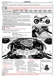
SAFETY INFORMATION 251262.2. Safety Labels - LocationEN21 - Front fairing function2 - Documentation warning3 - Battery warning4 - Unleaded gasoline5 - Emission control6 - Information on emission control7 - Information on gas emissions,exhaust silencers8 - Certification-Tire Information9 - Front fork foot warning10 - Rearview mirrors11 - Rear shock absorber12 - Rear wheel hub warning710101 4 32NOTE: The labels in the followingpages do not appear in their real size.If you experience difficulties in understandingany of these labels, contactan authorized <strong>MV</strong> <strong>Agusta</strong> dealer.1198- 38 -
SAFETY INFORMATION 22EN1. ADHESIVE LABEL –FRONT FAIRINGFUNCTION2. ADHESIVE LABEL –DOCUMENTATIONWARNING- 39 -
SAFETY INFORMATION 23. ADHESIVE LABEL –BATTERY WARNINGEN24. ADHESIVE LABEL –UNLEADED GASOLINE- 40 -
SAFETY INFORMATION 28000B36972EN5. ADHESIVE LABEL –EMISSION CONTROLMOTORCYCLE NOISE EMISSION CONTROL INFORMATIONTHIS 2010 <strong>MV</strong>A44F1000 MOTORCYCLE, MEETS US EPA NOISE EMISSIONREQUIREMENT OF 80 dBA AT 7095 RPM BY THE FEDERAL TEST PROCEDURE.MODIFICATIONS WHICH CAUSE THIS MOTORCYCLE TO EXCEED FEDERAL NOISESTANDARDS ARE PROHIBITED BY FEDERAL LAW. SEE OWNER'S MANUAL.Motor S.p.A.VARESE - ITALY- 41 -
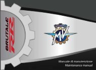
SAFETY INFORMATION 2EN26. ADHESIVE LABEL –INFORMATION ONEMISSION CONTROLENGINE DISPLACEMENT : 998 ccENGINE FAMILY : A<strong>MV</strong>AC.998 MHCENGINE EXHAUST CONTROL SYSTEM:TWC + SFI + PAIR + H02STHIS VEHICLE CONFORMS TO US EPA AND CALIFORNIAREGULATIONS APPLICABLE TO 2010 MODEL YEARNEW MOTORCYCLES AND IS CERTIFIED TO 0.8 g/km HC + NOx,12.0 g/km CO EXHAUST EMISSION STANDARD IN CALIFORNIAITEM SPECIFICATIONS INSTRUCTIONSIGNITION TIMING :IDLE SPEED RPM (NEUTRAL) :IDLE MIXTURE :No Adjustment1150 + - 100No AdjustmentVALVE CLEARANCE (mm) : IN 0.15 .0.24 / EX 0.20 .0.29SPARK PLUG : NGK CR9 EB GAP (mm): 0.7 .0.8UNLEADED OCTANE90 R + M/2SPECIFICATIONSOIL : SAE 10 W 60TYPE : SYNTHETIC A.P.I. SJEVAPORATIVE FAMILY: A<strong>MV</strong>AU0018MHCPERMEATION FAMILY: A<strong>MV</strong>APP105R01CANISTERHOT AIR INLETMANIFOLD 4MANIFOLD 3JETMANIFOLD 2MANIFOLD 1Motor s.p.a. VARESE - ITALY<strong>MV</strong> AGUSTA USA LLC - WILLOW GROVE, PA8000B3698- 42 -
SAFETY INFORMATION 22EN7. STAMPING ON EXHAUSTSILENCERS –EMISSION INFORMATION- 43 -
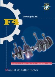
SAFETY INFORMATION 2EN28. ADHESIVE LABEL –CERTIFICATION – TIREINFORMATIONMANUFACTURED BY :Motor S.p.A. DATE :VARESE - ITALYTYPE OF VEHICLE: MOTORCYCLEGVWR 833 lbs 378 kg VIN:G A W R TIRE - DIMENSION - RIM COLD INFL. PRESS.lbs kgpsi kPaF 337 153 120 /70 ZR 17 M/C ( 58W ) 3.50 x 17 33.0 227R 556 252 190/55 ZR 17 M/C ( 75W ) 6.00 x 17 33.0 227THIS VEHICLE CONFORMS TO ALL APPLICABLE FEDERAL MOTOR VEHICLESAFETY STANDARDS IN EFFECT ON THE DATE OF MANUFACTURE SHOWN ABOVE.8000B36969. ADHESIVE LABEL –FRONT FORK FOOTWARNING- 44 -
SAFETY INFORMATION 2OBJECTS IN MIRROR ARE CLOSERTHAN THEY APPEAR2EN10. ADHESIVE LABEL –REARVIEW MIRRORS11. ADHESIVE LABEL –REAR SHOCK ABSORBERWARNINGCONTAINS HIGHLY COMPRESSED GASUSE ONLY PERFECTLY DRY NITROGEN GASOTHER GASES MAY CAUSE EXPLOSIONDO NOT INCINERATE REFER TO OWNER’SMANUAL FOR REGULATING GASSACHS- 45 -
SAFETY INFORMATION 2EN212. ADHESIVE LABEL –REAR WHEEL HUBWARNING- 46 -
SAFETY INFORMATION 2Before each ride, it is essential to verify the operation of the visual and acoustic signals.Turn indicators (§3.3.)Rear reflectorPlate light (lights up whenparking lights are turned on)2EN2.3. Safety - Visual and acoustic signalsRear side reflectorTurn indicators (§3.3.)Horn (§3.3.)Parking lights, lowand high beams (§3.3.)Rear side reflectorParking light (§3.3.) and brake light(lights up operating the brakes)Front side reflector- 47 -
CONTROLS AND INSTRUMENTS 33.1. Location of controls and instrumentsEN3Instruments and warning lights (§3.7.)Rearview mirror (§5.1.)Clutch lever (§5.1.)Left handlebar electrical controls (§3.3.)Rearview mirror (§5.1.)Front brake lever (§5.1.)Throttle twist grip (§3.4.)Ignition switch and steering lock (§3.5.)Fuel tank cap (§4.5.)Right handlebar electrical controls (§3.4.)Gear lever (§3.6. and §5.1.)Rear brake lever (§5.1.)Sidestand (§3.2.)Left sideRight side- 48 -
CONTROLS AND INSTRUMENTS 3KickstandDual returnspring3EN3.2. KickstandThe kickstand is equipped with a safetyswitch that prevents motorcycleoperation while the stand is down.If the rider attempts to engage thegears while the engine is running andthe stand is down, the safety switchautomatically turns off the engine bycutting the current supply.If the motorcycle is parked (kickstanddown) and the gears are engaged, theswitch prevents the engine from beingstarted.WARNING: Riding with thekickstand incompletelyretracted can result in anaccident when you turn left.Always retract the kickstandcompletely before starting off.WARNING: At least onceeach month, check that thesafety switch is properly activatedby the kickstand and isoperational.Safety switch- 49 -
CONTROLS AND INSTRUMENTS 3Horn buttonPress to operate the warning horn.Turn indicator switchShifting the lever to the left or right switches on the leftor right turn indicators. The switch then returns to thecentral position. Press to turn off the indicators.Clutch leverMove towards/away from the handgrip torelease/engage the clutch.3.3. Handlebar controls, left sideEN3High beam flasher buttonPress the button repeatedly.Low/high beam buttonButton not pressed in : low beamButton pressed in : high beam- 50 -
CONTROLS AND INSTRUMENTS 3High beam flasher buttonIt is used to attract the attention of other road users in case of danger or emergency. When the highbeam is on, the button is inactive.Low/high beam buttonUnder normal conditions, the low beam is on. The high beam can be switched on by pressing the buttonwhen allowed by the traffic and road conditions.Horn buttonIt is used to attract the attention of other road users in case of danger or emergency.WARNINGAlways use your turn indicators correctly. Use them to signal your intention before youstart a turn, and turn them off when you have completed the turn. Failure to observe thiswarning could lead other users of the road to draw incorrect conclusions about your intentionsand the motion of your motorcycle, resulting in a collision, with subsequent seriouspersonal injury or even death.3ENTurn indicator switchIt is used to show the rider’s intention to change direction or lane.Clutch leverIt engages/disengages the clutch through a hydraulically controlled device.- 51 -
CONTROLS AND INSTRUMENTS 33.4. Handlebar controls, right sideEN3Engine stop switchStops the engine and prevents it from being restarted.Engine start buttonStarts the engine. To be released as soon as the engine starts.When the engine is running, pressing the button selects thedisplay functions.Cold start (choke) leverRotate clockwise when cold starting. After the engine has run fora few seconds, return the lever to its original position.Throttle twist gripRotate counterclockwise to increase engine speed.Front brake leverPull to the lever to apply the front brake.- 52 -
CONTROLS AND INSTRUMENTS 3Engine stop switchIt is used to switch off the engine in an emergency. The ignition circuit is disabled, preventing the enginefrom being restarted. To be able to restart the engine, return the switch to its original position.DANGER! If the throttle of your motorcycle sticks, you must use the engine stop switch tostop the delivery of power from the engine. Failure to use the stop switch in such a situationcan result in loss of control of your motorcycle, serious injury or even death.DANGER! Before restarting the engine, you must determine the cause of the stuck throttleand effect the necessary repair. If necessary, take your motorcycle to a qualified mechanic.Failure to do so could result in an accident, personal injury or death.Engine start buttonIt is used to start the engine and, when the engine is running, to select the different functions of the displayinstalled on the instrument panel.CAUTION: To avoid damaging the electrical equipment, be sure not to hold down the buttonfor longer than 5 consecutive seconds.If, after some attempts, the engine does not start, refer to the chapter “TROUBLESHOOT-ING” later in this manual.3ENNOTEUnder normal conditions, do not use this switch to shut off the engine.- 53 -
CONTROLS AND INSTRUMENTS 3Cold start (choke) leverIt facilitates cold starting by slightly enrichening the fuel-air mixture during start-up.NOTE: Apply the choke lever for as short a period as possible. Once the engine idles normally,return the lever to its original position.Front brake leverIt controls a hydraulic circuit that operates the front wheel braking system.Proper use of the front brake is critical to achieve maximum braking performance of your motorcycle. <strong>MV</strong><strong>Agusta</strong> strongly recommends that you take a motorcycle riders training course to learn how to properlyuse the front brake.WARNING: Improper use of the front brake can result in loss of control of the motorcycle,an accident, personal injury or death.WARNING: Exercise extreme caution when using the front brake on wet or slippery surfaces,or on surfaces covered with sand, loose gravel, etc.EN3Throttle twist gripIt controls the fuel-air mixture supplied to the engine, which regulates engine speed. To increase enginespeed, rotate the hand grip from its idle position counterclockwise.When cold starting (choke on), rotating the throttle twist grip clockwise fully and repeatedly causes thechoke lever to return to its original position.- 54 -
CONTROLS AND INSTRUMENTS 33.5. Ignition switch and steering lockWARNING: Never attach a ring or any otherobject to the ignition key as they may hinder thesteering action. Failure to observe this warningcan lead to loss of control of the motorcycle,resulting in an accident, personal injury or death.WARNINGNever attempt to change the switch functionswhile you are riding. This could cause loss ofcontrol of the motorcycle, resulting in an accident,personal injury or death.The ignition switch enables and disables the electricalcircuit and the steering lock. The four positions of theswitch are described below.OFF positionAll electrical circuits are deactivated. The key can beremoved.ON positionAll electrical circuits are activated. The instruments andwarning lights perform the self-diagnostic cycle. Theengine can be started. The key cannot be removed.- 55 -“OFF”“ON”CAUTIONDo not leave the key on the ONposition for a long time when theengine is not running, in order toavoid damage to the electricalparts of the motorcycle.3EN
CONTROLS AND INSTRUMENTS 3Right sideEN3LOCK positionTurn the handlebar to the left or right. Press the key ingently while rotating it to the LOCK position.All electrical circuits are deactivated and the steering islocked. The key can be removed.Left side- 56 -
CONTROLS AND INSTRUMENTS 36°5°1°4°3°2°NP (PARKING) positionTurn the key from the LOCK position to the P position.All electrical circuits are deactivated except the parkinglights. The steering is locked. The key can be removed.CAUTIONDo not leave the key on the P position for along time, in order to avoid discharging thebattery of your motorcycle.3EN3.6. Gear leverThe N (neutral) position is indicated by the indicator lighton the instrument panel.To change into first gear, push the lever down.To change into second gear, lift the lever up. Lifting thelever up repeatedly engages all the other gears in successionup to the sixth speed.- 57 -
CONTROLS AND INSTRUMENTS 3SET button(§3.7.2.)OK button(§3.7.2.)3.7. Instruments and warning lightsThe instruments and warning lights are activated by turning the ignition switchto the ON position. After a preliminary check (approx. 7 seconds) the displayedinformation reflects the current general condition of the motorcycle.EN3Warning lights(§3.7.1.)Tachometer displayHAZARD button (§3.7.2.)Multifunction display (§3.7.2.)- 58 -
CONTROLS AND INSTRUMENTS 33.7.1. Warning lightsHigh beam (blue)It turns on when the high beam is on.Engine oil pressure warning lights (red)Lights up when the oil pressure is insufficient.Turn indicator light (green)Lights up when the turn indicatorsare activated.3ENNeutral warning lights (green)It turns on when the gear is in“Neutral”.WARNING: If the warninglight comes on while riding,stop the motorcycle immediately.Check the oil leveland if necessary have itrestored by a <strong>MV</strong> <strong>Agusta</strong>authorized service center(see §3.8.). If the warninglight comes on even if theoil level is correct, do notresume riding and contact a<strong>MV</strong> <strong>Agusta</strong> authorized servicecenter.Battery charge indicator (red)Lights up when the alternatordoes not supply enough currentto charge the battery. If the indicatorcomes on while riding, contactan authorized service center.Sidestand down warning light (red)Lights up when the sidestand is down.Rev limiter warning light (red)It turns on when the engine exceeds 10800 rpm;the rev limiter limits the rpm to 13500.Reserve fuel indicator (orange)Comes on when approximately 4 litres of fuel are left.- 59 -
CONTROLS AND INSTRUMENTS 3EN33.7.2. Multifunction displayGear displayIt displays the currently engaged gear.“N” stands for “neutral”.ThermometerIt displays the temperature of thecoolant by turning on a variablenumber of segments on a graduatedscale. When the temperaturefalls outside the normal operatingrange, it may display one of thefollowing information:- the display shows just one blinkingsegment; it means that thetemperature is low;- all segments are on, while theupper segment is blinking; itmeans that the temperature ishigh.Danger - Notice: if the temperature is high, stopthe motorbike and check the coolant level. If itneeds to be filled up, contact a <strong>MV</strong> <strong>Agusta</strong> licensedservice center (see § 6.3). If the warning light turnson even if the level is adequate, stop driving andcontact a <strong>MV</strong> <strong>Agusta</strong> licensed service center.SpeedometerIt displays the speed of the motorbike. It can be givenin kilometres per hour (Km/h) or in miles per hour(Mph). The full scale measures 350Km/h (217 Mph).“SPORT” ModeIt puts the injection unit in SportMode.“SET” buttonPress it to select and set the figureson the display.“OK” buttonPress it to confirm the new settings.“HAZARD” buttonPress it to turn on the emergencylights.“TOTAL” odometer:It displays the total distance covered; from 0 to 999999 (Km or miles)Trip counter 1, “TRIP 1”It displays the length of a trip; from 0 to 999.9 (Km or miles)Trip counter 2, “TRIP 2”It displays the length of a trip; from 0 to 999.9 (Km or miles)ChronometerIt displays the time measured by the chronometer- 60 -
OPERATION 4EN4This section provides the basic information needed to correctly operate the motorcycle:WARNING: Your motorcycle possesses very high power and performance characteristics.Therefore, its use requires a higher level of motorcycle riding skill and knowledge of themotorcycle. When you begin riding this motorcycle, you must ride especially carefully untilyou are thoroughly familiar with the motorcycle’s power and performance characteristics.Failure to do so could result in an accident, personal injury or death.CAUTION: The high temperatures caused by the use of the vehicle on race circuits couldcompromise the efficiency of the catalytic converter and of the exhaust system; therefore,we suggest installing a special exhaust system when using the vehicle on race circuits.<strong>MV</strong> <strong>Agusta</strong>, in order to protect the interests of the community, alerts the Customers and the Technical Assistance operatorsto use the vehicle and dispose of its replaced parts respecting the laws in force concerning environmental pollution and waste4.1. Using the motorcycle– Break-in ( § 4.2. )– Starting the engine ( § 4.3. )– Selecting and setting the display functions ( § 4.4. )– Refuelling ( § 4.5. )– Glove compartment ( § 4.6. )– Parking the motorcycle ( § 4.7. )– Checks to be performed before riding ( § 4.8. )Respect and defend natural environmentEverything we do affects the whole planet as well as its resources.disposal and recycling.- 61 -
OPERATION 44.2 Break-inCAUTIONFailure to observe the indications providedbelow can reduce performance and shortenthe life of the motorcycle.MAX5500-6000 rpmEN4Break-in is generally considered to apply only to theengine. In fact, it should be regarded as an essentialphase for other important parts such as the tires, thebrakes and the drive chain. During the very first miles,adopt a relaxed riding style.❏ 0 to 500 km (0 to 300 mi) (A)Frequently change the engine speed. If possible, preferhilly routes with gentle slopes and many bends. Avoidlong straight stretches.WARNING: New tires are sometimescoated with a mold releaseagent which makes them slippery.Abrupt acceleration, sharp turningor hard braking could cause youto lose control of your motorcycle.Ride at reduced speeds and exerciseextreme caution during thefirst 100 km (62 miles) when themotorcycle is new and after thereplacement of a tire.- 62 -
OPERATION 44EN❏ 500 to 1000 km (300 to 600 mi)Avoid low or high engine speeds and vary your speedfrequently. Do not exceed the engine speed shown inthe figure.MAX8000-9000 rpm❏ 1000 to 2500 km (600 to 1600 mi)Higher engine performance can be demanded, but it isadvisable not to exceed the engine speed shown in thefigure.MAX11000 rpm- 63 -
OPERATION 44.3. Starting the engineEN4WARNINGStarting the engine in a closed place can bedangerous. Exhaust emissions contain carbonmonoxide, a colorless and odorless gasthat can lead to serious harm or even deathwhen inhaled.Only start the engine outdoor, in the open air.As you turn the ignition switch to the ON position, theinstruments and the warning lights will go through theself-diagnostic cycle; during this phase, make sure thatall the warning lights on the dashboard come on. One ofthe following conditions must be verified, in order thatthe ignition switch system allows engine starting:– The gears are in neutral.– The gears are engaged, the clutch lever is pulledand the kickstand is up.- 64 -
OPERATION 44ENIf the self-diagnostic cycle detects a fault in the vehicle,the display shows the warning alert shown in thepicture. In particular, this message highlights the vehiclepart or device on which the fault has been detected.Press “OK” button to access to “RUN” mode.WARNINGIf a fault is detected on the vehicle, do notstart engine and contact an authorized <strong>MV</strong><strong>Agusta</strong> center.- 65 -
OPERATION 4CHOKE lever❏ Cold startingTurn the “CHOKE” lever without turning the acceleratorhandle.CHOKE leverEN4Press the starter button.As soon as the engine starts, release the button andwhen just slightly warmed up bring the “CHOKE” leverback to its starting position.START button- 66 -
OPERATION 4❏ Hot startingPress the start button without turning the throttletwist grip.START buttonAs soon as the engine starts, release the button.CAUTION• Do not press the start button for longer than5 consecutive seconds, in order to avoid damageto the electrical equipment.• Avoid warming up the engine while the vehicleis stationary. The subsequent engine overheatingcan cause damage to the internalparts of the engine. It is advisable to bring theengine to the working temperature by ridingat reduced speed.• To ensure the maximum life of the engine,never speed up at full throttle when the engineis cold.4EN- 67 -
OPERATION 44.4. Selecting and setting the display functionsSome of the main measurements of the instrumentsmay be changed.The available options include:EN4- Select an operating mode:“RUN” (Odometer)“TC” (Traction control)“CHRONO” (Chronometer)“NIGHT/DAY” (Night/Day Mode)- Reset the trip counter:Trip counter 1 “TRIP 1”Trip counter 2 “TRIP 2”- Turn on the chronometer- “IMMOBILIZER” mode (Antitheft device)- Control unit mapping selection- 68 -
OPERATION 4WARNINGThe operation must be performed while the engine isnot running, the gears are in neutral, the motorcycleis stationary, and with the feet on the ground. Do notset the display functions while riding.4.4.1. Selecting the display functionsThe following settings may be changedon the display:• “RUN” (Odometer)• “TC” (Traction control)• “CHRONO” (Chronometer)• “NIGHT/DAY” (Night/Day Mode)To display the operating modes, press“SET” for less than four seconds. Whenpressed, the display shows all modes,in a sequence. Select the desiredmode.4EN- 69 -
OPERATION 4❏ “RUN” modeIn addition to the speedometer, the display shows thefollowing functions (see §4.4.2.):• Total odometer “TOTAL”• Trip counter 1 “TRIP 1”As an alternative:EN4• Total odometer “TOTAL”• Trip counter 2 “TRIP 2”❏ “TC” ModeThis Mode adjusts the engine traction control level toyour driving requirements (see §4.4.3.).- 70 -
OPERATION 4EN❏ “CHRONO” ModeThis mode turns on the Chronometer and saves therecorded information (see §4.4.4.).The following is displayed:• Chronometer Current lap “CURRENT LAP”• Chronometer Fastest lap “BEST LAP”• Chronometer Last lap “LAST LAP”• Rev counter Total laps covered “N° LAP”4❏ “NIGHT/DAY” ModeThis function enables the background colour of the displayto be converted in order to adapt its visibilitydepending on the time of day or night the vehicle is used(see §4.4.5.).- 71 -
OPERATION 44.4.2. Trip resetTo reset “TRIP 1” and “TRIP 2”, proceed as follows.EN4WARNINGThe display modes may be changed or setwhen the engine is off, the gear in neutral, themotorbike stationary with your feet on theground. The display may not be changedwhile driving.Access the “RUN” mode; the total speedometer("TOTAL”) and partial speedometer 1 (“TRIP 1”) willappear on the display.By pressing the “OK” key for more than four seconds,the “TRIP 1” value will be reset to zero.- 72 -
OPERATION 44ENPress the “OK” key for less than four seconds untilthe partial speedometer 2 function (“TRIP 2”) appearson the display.By pressing the “OK” key for more than four seconds,the “TRIP 2” value will be reset to zero.- 73 -
OPERATION 44.4.3. “TC” ModePress “SET” in order to access to “TC” mode, thenpress “OK” for less than four seconds until “TC LEVEL”appears. The current traction control level is the sameas the one shown on the display.EN4WARNINGThe display modes may be changed or setwhen the engine is off, the gear in neutral, themotorbike stationary with your feet on theground. Do not change the display while driving.Press “SET” for less than four seconds: the tractioncontrol level rises up to the next value. Such value mayrange between 0 and 8.Press “OK” for over four seconds to confirm theselected traction control level.- 74 -
OPERATION 44EN4.4.4. Chronometer❏ Lap time recordingTurn on the chronometer (“CHRONO” mode) torecord the time taken to cover a lap.Press the headlight button to start recording thetime. The colon that separates the minutes from theseconds and from the tenths of a second will start blinking.Now, the instrument is recording the time.- 75 -
OPERATION 4Press the headlight button again to record the timetaken to cover the 1st lap. At the same time, the instrumentstarts recording the time taken to cover the secondlap.EN4The time measurement for the first lap is stored in thememory and is visualised on the display for ten seconds,after which the time measurement for the followinglap appears.If using the chronometer again, every time you pressthe headlight button, it records a time. The instrumentcan record up to100 consecutive times.When the time for the lap which has just concluded is displayed,the symbol “+” or “-” appears if the time recordedis respectively higher or lower than the time measuredduring the previous lap.- 76 -
OPERATION 4❏ Data displayOnce all times have been recorded, they may bedisplayed.Access the “CHRONO” mode; the time of the fastestlap (“BEST LAP”) and the time of the last lap (“LASTLAP”) appears on the display.WARNINGThe display modes may be changed or setwhen the engine is off, the gear must be inneutral, the motorbike must be stationary withyour feet on the ground. Do not change thedisplay while driving.4ENPress “OK” for less than four seconds until “LAPSVIEW” appears.- 77 -
OPERATION 4By repeatedly pressing the key of the flashing highbeam headlight, all the times previously acquired startingfrom the last lap memorised can be displayed insequence.EN4Once all the data have been displayed, press the“SET” key to return to the “LAPS VIEW” mode and thento the following mode.- 78 -
OPERATION 4❏ How to delete dataTo delete the saved data, proceed as follows:WARNINGThe display modes may be changed or setwhen the engine is off, the gear in neutral, themotorbike stationary with your feet on theground. Do not change the display while driving.Resetting of individual time recordings: Access the“CHRONO” mode and press the “SET” key for less thanfour seconds until the words “SINGLE LAP RESET”appear on the display.4ENPress the “OK” key for less than four seconds; thevalue of the last lap time memorised will start flashing.- 79 -
OPERATION 4Now, press “OK” for over four seconds to delete thevalue. Otherwise, press “SET” for less than four secondsto stop the deletion procedure.EN4Subsequently, by pressing the flashing high beamheadlight key followed by the “OK” key for more thanfour seconds, all the previously acquired times can becancelled.Once all the data have been cancelled, press the“SET” key to return to the “LAPS VIEW” mode and thento the following mode.- 80 -
OPERATION 44ENResetting of best lap time: Access the “CHRONO”mode and press the “SET” key for less than four secondsuntil the words “BEST LAP RESET” appear on thedisplay.Press the “OK” key for less than four seconds; thevalue of the fastest last lap time memorised will startflashing.- 81 -
OPERATION 4Now, press “OK” for over four seconds to delete thevalue. Otherwise, press “SET” for less than fourseconds to stop the deletion procedure.EN4Once all the data have been cancelled, press the“SET” key to exit the “BEST LAP RESET” mode andthen pass to the following mode.Resetting of all lap times recorded: Access the“CHRONO” mode and press the “SET” key for less thanfour seconds until the words “ALL LAPS RESET”appear on the display.- 82 -
OPERATION 44ENPress the “OK” key for less than four seconds; thedisplay will ask you to confirm cancellation of all thedata present in the memory.By pressing the “OK” key for more than four seconds,all the previously acquired times will be cancelled.By pressing the “SET” key for less than four seconds,the cancellation procedure will be interrupted.Once all the data have been cancelled, press the“SET” key to exit the “ALL LAPS RESET” mode and toreturn to the “CHRONO” mode.- 83 -
OPERATION 44.4.5. “NIGHT/DAY” ModeTo convert the display background colour, access the“NIGHT/DAY MODE” and press the “OK” key for lessthan four seconds.EN4WARNINGThe display modes may be changed or setwhen the engine is off, the gear in neutral, themotorbike stationary with your feet on theground. Do not change the display while driving.By pressing the "SET” key, the daytime and nighttimedisplay modes can be changed repeatedly.Once the display background colour has beendefined, press the “OK” key for more than four secondsin order to confirm the chosen display mode and toreturn to the “NIGHT/DAY MODE”. The defined backgroundcolour will be maintained in all the subsequentmodes of use of the dashboard.- 84 -
OPERATION 44.4.6. “IMMOBILIZER” ModeThe “IMMOBILIZER” lets the engine start only if itrecognises the original starter key. This is actually ananti-theft device built into the electronic circuit of thevehicle, since only authorised people are allowed todrive it.Use the dashboard “IMMOBILIZER” only in the event ofa breakdown. If for any reason the original key is notrecognised by the system, to let the engine start youmust manually enter the secret code, which is on the<strong>MV</strong> Code Card that was handed out to you with themotorbike.Remove the lid from the box on the back of the <strong>MV</strong>Code Card and read the secret electronic code of thestarter key (the figure shows a random code, for informationonly).4ENAccess to “RUN” mode and press “SET” for overeight seconds until “IMMOBILIZER” appears.- 85 -
OPERATION 4WARNINGThe display modes may be changed or setwhen the engine is off, the gear in neutral, themotorbike stationary with your feet on theground. Do not change the display while driving.EN4Press “OK” for less than four seconds to set the firstdigit of the code.Press “OK” for less than four seconds to set the firstdigit between 0 and 9.Once the digit has been selected, press “OK” forover four seconds to confirm the first digit of the code.Now, you can set the second digit of the code.Do the same to set the other four digits of the code.- 86 -
OPERATION 44ENOnce the full code has been entered, “CONFIRM-CODE” appears on the display. Press “OK” for over fourseconds to confirm the code.If the entered code is recognised by the system,“VALID CODE” appears. The dashboard display goesback to “RUN”. The engine may be started.If the entered code is wrong, “NOTVALID CODE”appears. The system will not let the engine start; thedisplay goes back to “IMMOBILIZER”. Repeat the codeentry procedure from the start, taking care of setting allthe right digits shown on your <strong>MV</strong> Code Card. If the problempersists, contact a <strong>MV</strong> <strong>Agusta</strong> licensed servicecenter.- 87 -
OPERATION 44.4.7. How to select the mapping of the control unitIn the F4 1000 model you may select a special mappingof the control unit, which will enable you to achievehigher power and efficiency for a briskly drivingexperience.EN4The mapping of the control unit can be selected bypressing the start button when the engine is switchedon. “SPORT” appears on the dashboard display toshow the mapping has been selected.WARNINGThe mapping selection may be changed orset when the engine is on, the gear in neutral,the motorbike stationary with your feeton the ground. Do not change the displaywhile driving.- 88 -
OPERATION 44.4.8. Warning/malfunction alertsThe dashboard may highlight the presence of a fault ora malfunction during different using conditions of themotorcycle.Engine start: As you turn the ignition switch to the ONposition, the instruments and the warning lights will gothrough the self-diagnostic cycle. If the self-diagnosticcycle detects a fault in the vehicle, the display showsthe warning alert shown in the picture. In particular, thismessage highlights the vehicle part or device on whichthe fault has been detected.Press “OK” button to access to “RUN” mode.4ENWARNINGIf a fault is detected on the vehicle when theengine is off, do not start engine and contactan authorized <strong>MV</strong> <strong>Agusta</strong> center.- 89 -
OPERATION 4Fault during vehicle riding: If a fault is detectedduring riding, the lower portion of the display shows thewarning alert shown in the picture.EN4WARNINGIf a fault is detected during riding, stop thevehicle and contact an authorized <strong>MV</strong> <strong>Agusta</strong>center.After the vehicle is stopped, the display shows thewarning message highlighting the vehicle part or deviceon which the fault has been detected.- 90 -
OPERATION 44ENHigh coolant temperature: If a high value of the coolanttemperature is detected, the display shows the warningalert shown in the picture. This message mayappear at any time during the use of the vehicle.WARNINGIf the coolant temperature is high, stop themotorbike and check the coolant level. If itneeds to be filled up, contact a <strong>MV</strong> <strong>Agusta</strong>licensed service center (see § 6.3). If the warningalert appears even if the level is adequate,stop driving and contact a <strong>MV</strong> <strong>Agusta</strong>licensed service center.- 91 -
OPERATION 44.5. RefuellingEN4WARNING: Before opening fuel cap, switchoff the engine, stop smoking, and keep awayfrom flames, sparks and heat sources. Failureto observe this warning can lead to a fire,resulting in an accident, personal injury ordeath.WARNING: Gasoline and its fumes are highlytoxic. Avoid contact and inhalation and performrefuelling in a well ventilated area.Failure to observe this warning can result inserious hazard to your health.CAUTION: Only use Unleaded Octane 90R +M/2 fuel. The green dot on the lower side ofthe tank cap and the label upon the fuel tankserve as a reminder of this.Lift the dust cover.Insert the key into the lock, rotate it clockwise and liftthe tank cap.After refuelling, press down the tank cap while rotatingthe key clockwise to facilitate the locking. Thenrelease the key and remove it.- 92 -
OPERATION 4WARNING: Never over fill the fuel tank. Overfilling may cause the fuel to overflow as aresult of the expansion due to the heat from the engine or to exposure to sunlight. Fuelspills can catch fire. The level of the fuel in the tank must never be higher than the base ofthe filler. Failure to observe this warning can lead to a fire or other damage, resulting in anaccident, personal injury or death.CAUTION: Immediately wipe any spilled fuel with a clean cloth, to avoid damage to thepainted or plastic surfaces.WARNINGVerify that the tank filler cap is correctly closed before using the motorcycle.4EN- 93 -
OPERATION 44.6. Glove compartmentInsert the key.Push the passenger seat downwards at theback and at the same time turn the key in a clockwisedirection.Lift up the passenger seat at the back end, letit slide backwards and remove.EN4In order to reassemble the above mentioned part,you must perform the following operations:• Rotate the key into the lock• Press down the passenger seat• Release the key• Press down the seat once more, so tomake sure of its firm coupling to theframe.WARNINGEvery time you lift or remove the passengerseat and every time the vehicle isused, make sure that the above mentionedpart is correctly placed and that itis firmly secured to the motorcycleframework.- 94 -
OPERATION 44.7. Parking the motorcycle❑ Using the kickstandWARNING• Park your motorcycle only on firm, levelground. Parking the bike on soft ground canallow the kickstand to dig in, and the motorcyclecan fall over resulting in an accident,personal injury or death.• If you must park the bike on a slope,engage first gear and park with the motorcyclefacing uphill. Remember to return thegear lever to neutral before restarting theengine.• Never leave your motorcycle unattendedwithout removing the key.Using your foot, lower the kickstand as far as it willgo, and then slowly tip the motorcycle toward you tobring the stand supporting foot into contact with theground’s surface.4EN- 95 -
OPERATION 4WARNING: Never sit on your bike when it is parked on the kickstand. This can damage thestand, and could cause the bike to fall over, with both damage to the motorcycle and possibleinjury to you.WARNING: Before riding off, ensure that the kickstand is fully retracted, and that the kickstandwarning light on the instrument panel is extinguished. Failure to observe this warningcan result in the stand contacting the ground as you are riding, which can upset the motorcycle,resulting in an accident, personal injury or death. If you notice a malfunction of the kickstandswitch, have it repaired by your <strong>MV</strong> <strong>Agusta</strong> dealer before using the motorcycle.EN4❏ Using the rear standInsert the stand pin into the rear wheelaxle hole on the left side of the motorcycle.Rest the stand on the ground and,pressing down on the stand, lift the vehicleuntil it reaches a stable condition.WARNING: This operation isbest carried out with two people,one to steady the motorcycleand one to manipulate the rearstand. Keep bystanders awayduring this operation.- 96 -
OPERATION 44EN4.8. Checks to be performed before ridingWARNING: A motorcycle can be in goodrunning order and then become unexpectedlyunreliable if it was unused for ashort or long period of time. You mustcarry out the inspections described inthe table below before each ride. A fewmoments taken to carry out theseinspections will help you maintain yourmotorcycle in optimum working orderand avoid unsafe situations that couldlead to loss of control of the motorcycle,serious injuries or even death.BrakesCheck fluid level (§ 6.8).Check for fluid leakage.Pull lever and press pedal to check brake operation.Check pads for wear (§ 6.7.)Lubricate the lever joint, if necessary.Gear leverPress pedal to check gear operation.Lubricate the lever joint, if necessary.Engine start button / stop switchCheck operation (§ 3.4).Clutch leverCheck fluid level (§ 6.9).Check for fluid leakage.Pull lever and check that it moves smoothly and gradually.Lubricate the lever joint, if necessary.Throttle twist gripCheck that grip rotates smoothly and returns to closedposition when released.Steering systemVerify that the operation is smooth and uniform.Check for play and loosening.Steering damperCheck adjustment (§ 5.6).Lights, visual and acoustic signalsCheck operation.TiresCheck inflating pressure and wear (§ 6.10).SuspensionsVerify that the operation is smooth and uniform.Check adjustment (§ 5.7 and § 5.8).Frame fastenersCheck tightening of all screws and nuts.Tighten them, if necessary.- 97 -
OPERATION 4EN4Drive chainCheck adjustment and lubrication (§ 6.11).CoolantCheck level (§ 6.6).Check for leakage.Engine oilCheck level (§ 6.5).Check for leakage.FuelCheck level.Refuel, if necessary (§ 4.5).Check for fuel leakage.KickstandCheck return to stowed position.Rear seatVerify that the rear seat is firmly secured to the framework.WARNINGIf any component does not pass thispre-riding inspection, have it repairedbefore operating the motorcycle. Failureto do so could result in an accident, personalinjury or death.- 98 -
OPERATION 45.1. List of adjustmentsThere are many adjustments that can significantlyimprove the ergonomics, geometry and safety of themotorcycle.WARNING: Many of these adjustmentsrequire specialized knowledge, tools andexperience. General mechanical aptitudeand tools may not be sufficient to properlyinspect, adjust, service or repair yourmotorcycle. If you have any doubts, pleasetake your motorcycle to an authorized servicecenter.WARNING: In order to maintain control ofyour motorcycle, always keep both handson the handlebars. Never attempt to performany of the adjustments listed herewhile you are riding, unless the text specificallyinstructs you to do so. Failure to heedthis warning can result in an accident, personalinjury or death.4EN- 99 -
ADJUSTMENTS 5(L) Drive chainadjustment (§5.2.)(E) Rearview mirror adjustment (§5.5.)(A) Clutch lever adjustment (§5.4.)(E) Rearview mirror adjustment (§5.5.)(F) Steering damper adjustment (§5.6.)(C) Gear lever adjustment (§5.2.)(H) Rear suspensionadjustment (§5.8.)EN5(D) Rear brake leveradjustment (§5.2.)(M) Headlightadjustment (§5.9.)(G) Front suspensionadjustment (§5.7.)(B) Front brake lever adjustment (§5.3.)- 100 -
ADJUSTMENTS 55.2. Table of adjustmentsA - Clutch lever adjustment: Optimizes the gripto suit the rider’s needs (§5.4).B - Front brake lever adjustment: Optimizesthe grip to suit the rider’s needs (§5.3).C - Gear lever adjustment: Optimizes the positionof the lever to suit the rider’s needs.D - Rear brake lever adjustment: Optimizes theposition of the lever to suit the rider’s needs.E - Rearview mirror adjustment: Optimizes theorientation of the rearview mirrors (§5.5).F - Steering damper adjustment: Adjusts thesteering stiffness to the rider’s preference (§5.6).- 101 -G - Front suspension adjustment: The followingcan be adjusted to adapt the response ofthe suspension to the rider’s preference:- spring preload (§ 5.7.1.)- rebound damper (§ 5.7.2.)- compression damper (§ 5.7.3.)H - Rear suspension adjustment: The followingcan be adjusted to adapt the response of thesuspension to the rider’s preference:- geometry height- spring preload- rebound damper (§5.8.1.)- high speed compression damper (§5.8.2.)- low speed compression damper (§5.8.3.)L - Drive chain adjustment: To ensure safe andeffective transmission of power.M - Headlight adjustment: To adjust the range of thelight beam to the geometry of the motorcycle (§5.9).5EN
ADJUSTMENTS 55.3. Adjusting the front brake lever5.4. Adjusting the clutch leverWARNINGNever perform the adjustment while riding.While gently pulling the lever against the spring, turnthe adjusting ring clockwise or counterclockwise tomove the lever away or toward the hand grip.WARNINGNever perform the adjustment while riding.While gently pulling the lever against the spring, turnthe adjusting ring clockwise or counterclockwise tomove the lever away or toward the hand grip.EN5- 102 -
ADJUSTMENTS 5Adjusting knob5EN5.5. Adjusting the rearview mirrorsWARNINGNever perform the adjustment while riding.Press the mirror at the points shown in the figure toadjust its position in the four directions.WARNINGCheck the rearview mirrors adjustment everytime you use your motorcycle.5.6. Adjusting the steering damperWARNINGNever perform the adjustment while riding.The standard adjustment is obtained by fully rotating theknob counterclockwise. In this position the damperoffers the least resistance to the rotation of the steering.To suit the rider’s needs, the action of the damper canbe gradually increased by rotating the knob clockwise.- 103 -
ADJUSTMENTS 5Compression damperSpring preload5.7. Adjusting the front suspensionWARNING: It is essential that theadjusters of both fork rods areadjusted to the same position.NOTEThe adjustment of the suspensionsmust be preferably performed withthe fuel tank full.Rebound damperEN5Spring preload- 104 -
ADJUSTMENTS 55EN5.7.1. Spring preload (front suspension)See the table in the enclosed sheet for spring preloadadjustment. Refer to the number of turnsfrom the fully counterclockwise position.CAUTION: Do not force the adjusting nut pastits fully counterclockwise position. Rotate theadjusting screw counterclockwise to decreasepreload, clockwise to increase preload.5.7.2. Rebound damper (front suspension)See the table in the enclosed sheet for rebounddamping adjustment. Refer to the number ofclicks from from the reference position, which isfound by fully turning the screw clockwise andthen counterclockwise until you hear the first click.CAUTION: Do not force the adjusting screwpast its fully clockwise position. Rotate theadjusting screw counterclockwise to decreasedamping, clockwise to increase damping.- 105 -
ADJUSTMENTS 55.7.3. Compression damper (front suspension)See the table in the enclosed sheet for rebounddamping adjustment. Refer to the number ofclicks from from the reference position, which isfound by fully turning the screw clockwise andthen counterclockwise until you hear the first click.CAUTION: Do not force the adjusting screwpast its fully clockwise position. Rotate theadjusting screw counterclockwise to decreasedamping, clockwise to increase damping.EN5- 106 -
ADJUSTMENTS 5WARNING: The rear shock absorber contains highly compressed gas. Do not try to open ordisassemble it in any way. Failure to heed this warning may lead to an explosion, resulting inan accident, personal injury or death.CAUTION: When you estimate the rear suspension settings, never push or pull in any wayon the exhaust mufflers. They would be certainly damaged.NOTE: At the moment of delivery of the motorcycle, the rear suspension is adjusted in thestandard configuration (see enclosed table).NO5EN5.8. Adjusting the rear suspensionWARNING: The high temperature of the exhaust pipes can cause burns. Before adjusting therear suspension, shut off the engine and wait until the exhaust pipes have thoroughly cooled.NO- 107 -
ADJUSTMENTS 5CLICK!CLICK!CLICK!EN5Low speed compression damperHigh speed compression damper5.8.1. Rebound damper (rear suspension)See the table attached to this manual for rebounddamping adjustment. Refer to the number ofclicks from the reference position, which is foundby fully turning the screw clockwise and thencounterclockwise until you hear the first click.CAUTION: Do not force the adjustingscrew past its fully clockwise position.Rotate the adjusting screw counterclockwiseto decrease damping, clockwise toincrease damping.Rebound damper- 108 -
ADJUSTMENTS 55EN5.8.2. High speed compression damper (rearsuspension)See the table attached to this manual for compressiondamping adjustment. Refer to the number ofclicks from the reference position, which is foundby fully turning the screw counterclockwise andthen clockwise until you hear the first click.CAUTION: Do not force the adjusting nut pastits fully counterclockwise position. Rotate theadjusting nut counterclockwise to decreasedamping, clockwise to increase damping.5.8.3. Low speed compression damper (rearsuspension)See the table attached to this manual for compressiondamping adjustment. Refer to the number ofclicks from the reference position, which is found byfully turning the screw clockwise and then counterclockwiseuntil you hear the first click.CAUTION: Do not force the adjusting screw pastits fully clockwise position. Rotate the adjustingscrew counterclockwise to decrease damping,clockwise to increase damping.CLICK!CLICK!CLICK!CLICK!CLICK!CLICK!- 109 -
ADJUSTMENTS 5Place the vehicle at a distance of 10 m (32.8 ft) from a vertical wall.Make sure that the motorcycle is placed on an even horizontal surface, and that the headlight’s optical axis isperpendicular to the wall. The vehicle must be held in an upright position. Measure the “X” distance betweenthe headlight center and the ground surface, then trace a small cross on the wall at the same height.When you turn the headlight on, the upper boundary line between the dark area and the lighted area must beat an height equal or lower than the 9/10 of the headlight center height (X).9/10XX5.9. Headlight adjustmentEN5Headlight center10 m (32.8 ft)- 110 -
ADJUSTMENTS 5Counterclockwise5ENThe light beam can be adjusted vertically by turningthe screw illustrated. If turned in a clockwisedirection: the optical unit tilts upwards. If turned inan anti-clockwise direction: the optical unit tiltsdownwards. It can be tilted up to an angle of ±4°from the standard position.Clockwise- 111 -
MAINTENANCE 6EN66.1. Tables of scheduled maintenance and checksThe periodic checks and maintenance operations that arerequired to keep your motorcycle safe and in perfect runningorder are shown in the following tables.WARNING: Many of these services and maintenancetasks require specialized knowledge, tools and experience.General mechanical aptitude and tools maynot be sufficient to properly service and maintainyour motorcycle. If you have any doubts, please takeyour motorcycle to an authorized service center.NOTE: Any damage to your motorcycle which is the resultof improperly performed maintenance is not covered bythe warranty.Most motorcycle maintenance operations must be performedwhile the bike is on the rear stand, the engine is off , and thestart switch is set to OFF. This does not apply to the checkingof fluid levels.Use only lubricants and fluids listed in this manual (see § 6.3).If your motorcycle is damaged by the use of improper lubricants,fluids, or other such products, this damage is not coveredunder the warranty.- 112 -
MAINTENANCE 6After the first 36,000 Km (22,400 miles) have elapsed, perform the maintenance operations at the sameintervals as those shown in the table.WARNINGObserve all the warnings, dangers and cautions related to the maintenance procedures aslisted throughout this manual. Failure to observe this warning can not only destroy yourmotorcycle, but can lead to serious injury or even death.WARNINGUsing low quality spare parts can result in unexpected failure, resulting in an accident, personalinjury or death. Always use genuine <strong>MV</strong> <strong>Agusta</strong> spare parts.Any damage to your motorcycle which is the result of the use of non-genuine spare partsis not covered by the warranty.WARNINGIf your motorcycle is involved in an accident, have all it thoroughly inspected by an authorized<strong>MV</strong> <strong>Agusta</strong> dealer. Failure to heed this warning and operating a motorcycle, which isunsafe, could lead to serious injuries or even death.Respect and defend natural environmentEverything we do affects the whole planet as well as its resources.<strong>MV</strong> <strong>Agusta</strong>, in order to protect the interests of the community, alerts the Customers and the Technical Assistance operatorsto use the vehicle and dispose of its replaced parts respecting the laws in force concerning environmental pollution and wastedisposal and recycling.6EN- 113 -
MAINTENANCE 6Electric fans Check operation ● ● ● ● ● ● ● ●Valves Check / Adjust ● ● ●●Tables of scheduled maintenancekm (miles) covered0 1000 6000 12000 18000 24000 30000 36000(600) (3800) (7500) (11200) (14900) (18600) (22400)Service couponPredeliveryA B C D E F GDESCRIPTIONEngine oilEngine oil filterOPERATIONCheck levelRenewReplace( Use only <strong>MV</strong> <strong>Agusta</strong>genuine spare parts )Check / Restore levelEvery time vehicle is usedAt least once a yearEvery time engine oil is changedEvery time vehicle is used● ● ● ● ● ● ●● ● ● ● ● ● ●EN6Coolant Check / Restore level ● ● ● ● ● ● ● ●RenewAt least every two yearsCooling system Check for leakage ● ● ● ● ● ● ● ●Timing chainCheck ● ●Replace- 114 -
MAINTENANCE 6Timing chain stretcher Check / Replace ● ● ●Fuel filter Check / Replace ● ● ●Throttle body Check and Adjust ● ● ● ● ● ● ●Air filter Check / Replace ● ● ● ● ● ●6ENTables of scheduled maintenancekm (miles) covered0 1000 6000 12000 18000 24000 30000 36000(600) (3800) (7500) (11200) (14900) (18600) (22400)Service couponPredeliveryA B C D E F GDESCRIPTIONTiming movable shoe●Every time timing chain is replacedOPERATIONCheck / Replace ● ●ReplaceSpark plugsCheck / Replace ● ● ●Replace ● ● ●Check levelEvery time vehicle is usedBrakes / Clutch fluidCheck level ● ● ● ● ● ● ●●RenewAt least every two years- 115 -
MAINTENANCE 6Brakes / Clutch Check operation ● ● ● ● ● ● ● ●Check lines for leakage ● ● ● ● ● ● ● ●Throttle control Check operation ● ● ● ● ● ● ● ●Check / Adjust play ● ● ● ● ● ● ● ●Choke control Check operation ● ● ● ● ● ● ● ●Tables of scheduled maintenancekm (miles) covered0 1000 6000 12000 18000 24000 30000 36000(600) (3800) (7500) (11200) (14900) (18600) (22400)Service couponPredeliveryA B C D E F GDESCRIPTIONOPERATIONCheck operationEvery time vehicle is usedEN6Brake pads( front and rear )Fuel lines and connectionsEvaporative emissioncontrol systemCheck wear Every 1000 Km ( 600 mi )Check / Replace ● ● ● ● ● ● ●Check for leakage ● ● ● ● ● ● ●ReplaceAt least every 3 yearsCheck / Adjust ● ●Check operationEvery time vehicle is used- 116 -
MAINTENANCE 6Check Every 1000 Km ( 600 mi )Drive chain Check / Adjust ● ● ● ● ● ● ● ●Lubricate ● ● ● ●Replace ● ● ●Check ● ● ● ●6ENTables of scheduled maintenancekm (miles) covered0 1000 6000 12000 18000 24000 30000 36000(600) (3800) (7500) (11200) (14900) (18600) (22400)Service couponPredeliveryA B C D E F GDESCRIPTIONFlexible controlsand transmissionsOPERATIONCheck / Adjust ● ● ● ● ● ● ● ●LubricateEvery 1000 Km ( 600 mi ) and after riding under the rainFront sprocket / Tab washerReplace● ● ●Every time drive chain is replacedRear sprocketCheck ● ● ● ●● ● ●ReplaceEvery time drive chain is replaced- 117 -
MAINTENANCE 6Steering head tube ring Check / Adjust ● ● ● ●●Tables of scheduled maintenancekm (miles) covered0 1000 6000 12000 18000 24000 30000 36000(600) (3800) (7500) (11200) (14900) (18600) (22400)Service couponPredeliveryA B C D E F GDESCRIPTIONOPERATIONRear sprocket spring drive Check / Replace ● ● ●Steering bearingsCheck / Adjust ● ● ● ●Lubricate●Check pressureEvery time vehicle is used; at least every 10 daysEN6TiresWheel rimsEvery time tire is replacedCheck wear Every time vehicle is used; at least every 500 Km ( 300 mi )Check pressure ● ● ● ● ● ● ● ●Check wear ● ● ● ● ● ● ●● ● ● ● ● ● ●Inspect visuallyFront wheel bearingsCheckReplace● ● ● ● ●Every time tire is replaced- 118 -
MAINTENANCE 6Drive chain pads on swingarm Check / Replace ● ● ● ● ● ● ●Drive chain pads on frame plate Check / Replace ● ● ● ● ● ● ●Rear shock absorber Check / Adjust ● ● ● ●Front fork oil Renew ●Battery connections Check and clean ● ● ● ● ● ● ●Electrical equipment Check operation ● ● ● ● ● ● ● ●6ENTables of scheduled maintenancekm (miles) covered0 1000 6000 12000 18000 24000 30000 36000(600) (3800) (7500) (11200) (14900) (18600) (22400)Service couponPredeliveryA B C D E F GDESCRIPTIONKickstandOPERATIONCheck operationEvery time vehicle is usedCheck operation ● ● ● ● ● ● ● ●Check operationEvery time vehicle is usedSide stand switchCheck operation ● ● ● ● ● ● ● ●Rear wheel hubCheck /Lubricateneedle bearing● ●Replace /Lubricateneedle bearing●Swingarm bearings Check / Lubricate ●- 119 -
MAINTENANCE 6Tables of scheduled maintenancekm (miles) covered0 1000 6000 12000 18000 24000 30000 36000(600) (3800) (7500) (11200) (14900) (18600) (22400)Service couponPredeliveryA B C D E F GDESCRIPTIONInstrument panelLights / Visual signalsHornOPERATIONCheck operationEvery time vehicle is usedCheck operation ● ● ● ● ● ● ● ●Check operation /Replace bulbsCheck operation /Replace bulbsEvery time vehicle is used● ● ● ● ● ● ● ●Check operationEvery time vehicle is usedCheck operation ● ● ● ● ● ● ● ●EN6Check operationEvery time vehicle is usedHeadlight Check operation ● ● ● ● ● ● ● ●AdjustEvery time geometry is changedIgnition switchLocksCheck operationEvery time vehicle is usedCheck operation ● ● ● ● ● ● ● ●Check operationEvery time vehicle is usedCheck operation ● ● ● ● ● ● ● ●- 120 -
MAINTENANCE 6Hose clamps Check / Tighten ● ● ● ● ● ● ● ●General lubrication ● ● ● ● ● ● ● ●General test ● ● ● ● ● ● ● ●Information on operations that are suggested to be performed by your authorized <strong>MV</strong> <strong>Agusta</strong> dealer.6ENTables of scheduled maintenancekm (miles) covered0 1000 6000 12000 18000 24000 30000 36000(600) (3800) (7500) (11200) (14900) (18600) (22400)Service couponPredeliveryA B C D E F GDESCRIPTIONOPERATIONScrews and nuts Check / Tighten ● ● ● ● ● ● ● ●In order to highlight symbols importance, remember the following information:Information on operations that can be carried out by the user.The “ ” symbol points out the requirement to use a tool or a special equipment in order to correctly performthe described operation.- 121 -
MAINTENANCE 66.2. Tools and accessories suppliedA bag in the glove compartment contains the followingtools:- 1 hexagonal bar with 10 mm (0.4 inch) hexagon;- 6 Allen keys with 2.5 - 3 - 4 - 5 - 6 - 8 mm (0.10 - 0.12- 0.16 - 0.20 - 0.24 - 0.32 inch) hexagons;- 1 spanner for rear wheel eccentric with extension;- 1 fuse puller;- 3 fuses (15 A).EN6The following accessories are also supplied:- 1 spark plug wrench (16 mm hexagon);- 1 document holder.- 122 -
MAINTENANCE 6Ethylene glycol diluteddistilled waterDescription Recommended product SpecificationsEngine lubrication oil AGIP RACING 4T 10W/60 (*) SAE 10W/60 - API SJCoolant AGIP ECO - PERMANENT with 50 percentBrake and clutch fluid AGIP BRAKE FLUID DOT4 DOT4Drive chain lubrication oil D.I.D. CHAIN LUBE –* : <strong>MV</strong> <strong>Agusta</strong> suggests to refer directly to its authorized dealers in order to purchase the recommendedproduct. The AGIP Racing 4T 10W/60 engine oil has been expressly produced for the F4 motorcycleengine. If the above described lubricant is not available, <strong>MV</strong> <strong>Agusta</strong>suggests to use a fully synthetic engine oil having characteristicsequal or better than the ones prescribed in the following standards:6.3. Table of lubricants and fluids– Consistent with: API SJ– Consistent with: ACEA A3– Consistent with: JASO MA– SAE Rating: SAE 20 W-50 o 10 W-60NOTEThe above standard denominations must be written, alone ortogether, on the engine oil container label.Engine oilSAE 10 W-60API SJACEA A3JASO MA6EN- 123 -
MAINTENANCE 66.4. Removing/fitting the right-hand side fairingPull off the quick fastenings and then remove the sidefairing.EN6- 124 -
MAINTENANCE 6Fit the side fairing, taking care to position the frontprofile as shown in figure A.Fasten the panel by positioning the tab in thelower part of the fairing as shown in figure B.6ENSide fairing frontprofileAB- 125 -
MAINTENANCE 66.5. Checking the engine oil levelEN6Check the oil level while the engine is not running, andhas been allowed to cool down for at least ten minutesafter a ride.The check must be performed after placing the motorcyclein an upright position on a horizontal surface.The level must be between the MAX and MIN marks onthe crankcase.If the oil level is below the MIN mark, top up asdescribed in § 6.5.1. Never exceed the MAX level.WARNINGNever run your motorcycle if the oil level isbelow the minimum mark. This could causeseizure, resulting in loss of control of themotorcycle, an accident, personal injury ordeath.MaxMin- 126 -
MAINTENANCE 66.5.1. Topping up the engine oil levelTo top up the engine oil level, first remove theright-hand side fairing (see § 6.4) to expose the oilfiller plug. Remove the oil filler plug by using the10 mm hexagonal bar supplied, assembled on aproper key (see figure). Pour an appropriateamount of engine oil of the recommended type(see § 6.3). Never exceed the MAX level mark.At the end of the operation, place back the oil fillerplug and reassemble the right-hand side fairing.WARNINGBefore reassembling the oil filler plug,grease its O-Ring by using AGIP Grease30. Replace the oil filler plug and tightenit to a torque of 35 Nm, by using a torquewrench. Failure to replace or tighten theoil filler plug may lead to oil spillage thatcould result in engine seizure, loss ofcontrol of the motorcycle, an accident,personal injury or death.Oil filler plugCAUTIONTo avoid clutch sliding and damage tothe engine, never add chemical additivesto the engine oil, nor use an engineoil different from the one specified in thetable at § 6.3. Make sure that no foreignbody gets in the crankcase while toppingup the engine oil.6EN- 127 -
MAINTENANCE 6WARNINGNew or used engine oil can be dangerous.Engine oil is highly toxic for peopleand domestic animals. Avoid ingestionand contact. It has been proved that prolongedcontact with engine oil cancause skin cancer. Even a brief contactwith engine oil can cause skin irritation.• In the event of an engine oil ingestion,immediately call a doctor and do notcause vomiting, in order to avoid inhalationof engine oil in lungs.• Keep new or used engine oil out ofreach of children and domestic animals.• While topping up the engine oil, weara long-sleeved shirt and a pair of waterproofgloves to protect your skin.• If the engine oil comes in touch withyour skin, wash it away with soap andwater.• Follow your local laws and/or environmentallaws to recycle or dispose of theused engine oil properly to avoid environmentalpollution.EN6- 128 -
MAINTENANCE 6MAXMIN6EN6.6. Checking the coolant levelCheck the coolant level after the engine has been shutoff for at least fifteen minutes after riding. If you attemptto check the coolant level while the engine is still warm,you will get an erroneous level indication.WARNING: Never attempt to remove the coolantcap when the engine is hot.The motorcycle must be positioned upright on a horizontalsurface to make this check.Ensure that the coolant level is between the MIN andMAX marks as shown in the figure.If the coolant level is below the MIN mark, top up thecoolant as described at paragraph 6.6.1.WARNING: Never run your motorcycle if thecoolant level is below the minimum mark.This could cause seizure, that can result inloss of control of the motorcycle, an accident,personal injury or death.- 129 -
MAINTENANCE 66.6.1. Topping up the coolant levelRemove the coolant filler cap and topup with the recommended coolant(see §6.3).EN6WARNINGThe cooling system is underpressure. Always very carefullyremove the coolant filler cap.Never attempt to remove thecoolant filler cap until the motorcyclehas completely cooled toroom temperature. Failure toobserve this warning will resultin coolant being splashed onyou with subsequent seriousburns and serious personalinjury. If you have the slightestdoubt that the motorcycle hascompletely cooled, do notremove the cap, but allow themotorcycle to completely cool.- 130 -
MAINTENANCE 66ENWARNINGUnder certain conditions, ethylene glycolcontained in the coolant can becomeflammable. When it is lighted, it producesan invisible flame.Avoid spilling coolant on hot parts ofthe motorcycle, because the subsequentcombustion of ethylene glycolcould cause serious burns and seriouspersonal injury.WARNINGCoolant is a highly toxic fluid. Avoidingestion and contact with your skin oreyes. Keep coolant out of reach of childrenand domestic animals. In the eventof a coolant ingestion, immediately calla doctor and do not cause vomiting, inorder to avoid inhalation of coolant inlungs. If the coolant comes in touch withyour skin or eyes, immediately wash itaway with water.CAUTIONUse only the coolant specified in thetable in section 6.3. Do not mix nordilute the coolant with additives or differentfluids. If the coolant specified insection 6.3. is not available, use acoolant having technical characteristicsconsistent with the prescribed product.See your <strong>MV</strong> <strong>Agusta</strong> dealer.CAUTIONDo not spill coolant on any part of themotorcycle. It will damage painted andplastic parts. If you do spill coolant onyour motorcycle, carefully flush thecoolant away with cool clear water.After topping up, carefully replace the cap and thepreviously removed parts.- 131 -
MAINTENANCE 6Front brake caliperRear brake caliperEN6DiscPadsWear limit 1 mm6.7. Checking the wear of the brake padsPeriodically check the width of the friction material layer ofthe pads, making sure it never falls below the wear limit (1mm-0.04 inch).WARNINGIf the brake pads are excessively worn, the effectivenessof the braking system decreases,increasing the risk of accidents, personal injury ordeath. If the pads have worn to near the wear limit,have both pads replaced by your <strong>MV</strong> <strong>Agusta</strong> dealer.Never replace just one pad, the pads mustalways be replaced in pairs. Ensure that the newpads are suitably broken in, see § 4.2.- 132 -
MAINTENANCE 6MaxMin6ENRear brake fluid reservoirFront brake fluid reservoirMaxMin6.8. Checking the brake fluid levelWARNINGBefore riding, always check the brakingsystem according to the instructionsprovided at § 4.8. of this manual.The level of the brake fluid decreases as thebrake pads wear down. Ensure that the fluid levelis always between the MAX and MIN marks. If thelevel falls below the MIN mark, contact an authorizedservice center and have the brake systemrepaired.- 133 -
MAINTENANCE 6EN6WARNINGNever use your motorcycle if the fluidlevel is below the MIN mark. The brakesmay fail to properly operate, resulting inan accident, personal injury or death. Ifthe brake fluid level is below the MINmark, the braking system must be overhauledby an authorized <strong>MV</strong> <strong>Agusta</strong>dealer.WARNINGBrake fluid replenishing must be performedonly by skilled personnel. Brakefluid is highly toxic. Avoid ingestion andcontact with your skin or eyes. Keepbrake fluid out of reach of children anddomestic animals. In the event of abrake fluid ingestion, immediately call adoctor and do not cause vomiting, inorder to avoid inhalation of brake fluidin lungs. If the brake fluid comes intouch with your skin or eyes, immediatelywash with water.WARNINGUse only the brake fluid specified atparagraph 6.3. of this manual. Mixing differentbrake fluids can cause a dangerouschemical reaction, as well as thedecrease of the braking efficiency. Thiscould increase the risk of accidents, withsubsequent serious injury or even death.WARNINGAn insufficient amount of brake fluid mayallow the introduction of air into thebraking system. This could compromisethe effectiveness of the braking system,resulting in an accident, personal injuryor death. Presence of air in the brakingsystem can be identified in the momentyou feel a characteristic “spongy effect”while pushing the brake lever. In thiscase, have a braking system bleedingperformed by an authorized <strong>MV</strong> <strong>Agusta</strong>dealer before riding your motorcycleagain.- 134 -
MAINTENANCE 6MaxMin6.9. Checking the clutch fluid levelThe fluid level must be between the MAX and MINmarks.If the level falls below the MIN mark, contact your <strong>MV</strong><strong>Agusta</strong> dealer and have the clutch control systemrepaired.WARNINGNever use your motorcycle if the fluid level isbelow the MIN mark. The clutch may fail toproperly operate which could result in an accident,personal injury or death. If the clutchfluid level is below the MIN mark, have theclutch system overhauled by an authorized<strong>MV</strong> <strong>Agusta</strong> dealer.6ENWARNINGUse only the clutch fluid specified in section6.3. of this manual.- 135 -
MAINTENANCE 66.10. Checking and replacing the tiresWARNINGBefore using the motorcycle,always check the pressure andwear of the tires. The tire airpressure must be checked andadjusted on cold tires.EN6Checking the air pressure of each tire isan essential requirement to ensure drivingsafety.Never exceed the maximum inflationpressure recommended by the tire manufacturer.Refer to the pressures given in §8.2. or on the label applied to the steeringhead tube. In the event of long rides, youcan increase the face value of the tirepressure by 0.2 bar (0.014 psi). In theevent of use of the motorcycle at a speedhigher than 300 km/h, increase the tyrepressure with reference to the valuesgiven in § 8.2.WARNINGIncorrect tire pressure can result in loss of controlof the motorcycle, an accident, personalinjury or death.- 136 -
MAINTENANCE 66ENExcessive tire pressure reduces grip on the roadand increases the risk that the tire will unexpectedlyburst. Inflation pressure that is too low reducestire performance and increases the probabilityof detachment of the tire from the rim, resulting insudden and unexpected loss of tire pressure. Inaddition, premature wear and damage to the rimmay occur. These conditions can cause loss ofcontrol of the motorcycle, resulting in an accident,personal injury or death.Before riding, it is therefore necessary to measurethe tire pressure at room temperature. Thevehicle must be parked at least three hours.Moreover, it is extremely important to check thewear of the tires before riding. In fact, a worn tirecan be punctured more easily than a new one,and it can adversely affect handling and stabilityof the motorcycle.Always check the depth of the tire tread. The treaddepth must always be at least 1/8 inch (3 mm).Verify the absence of crevices at the bottom of thetread design and fissures on the tire sidewall.Moreover, verify the absence of nails and glasssplinters in the tire. If you see any evidence orwear, have the tire replaced by an authorized <strong>MV</strong><strong>Agusta</strong> dealer.WARNING• Never ride your motorcycle if the tiresare cut, cracked, leaking or if there isdamage to the tread or sidewall. Neverride your motorcycle if the tires are notproperly inflated. If the tires of yourmotorcycle are worn, have themreplaced by your <strong>MV</strong> <strong>Agusta</strong> dealer.• If a tire is punctured it must bereplaced, not repaired. A repaired tireprovides a restricted performance andlower safety levels than a new one. Ifyou make a provisional or emergencyrepair to a tire, you must ride at verylow speed until you reach the nearest<strong>MV</strong> <strong>Agusta</strong> dealer and have the tirereplaced. With a provisionally repairedtire, never exceed 60 km/h (35 mph).- 137 -
MAINTENANCE 6EN6Tire repairing must never be performedif the tire is punctured on its sidewall, orif the diameter of the puncture on thetread is greater than 6 mm (0.24 inch).• Do not use sealing fluids to repair apunctured tire. These products canadversely affect the material of the tirelayers, as well as hide the minor damagescaused by objects penetrated in the tire.• When it is necessary to replace thetires, use only the type specified in section8.2. Moreover, avoid using tires of adifferent brand or type on the front andon the rear wheel at the same time.Using tires different from those specifiedcan adversely affect the handlingand stability of the motorcycle, increasingthe risk of accidents with subsequentserious injury or even death.• Have the tires replaced according totheir direction of spin, which is highlightedby a small arrow on the tire sidewall.• The wheel rims of your motorcyclehave been designed for use with tubelesstires only. Do not assemble an airtube tire on rims designed for tubelesstires. Otherwise, the tire bead could notproperly settle down on the wheel rim,leading to the deflation of the tire andthe loss of control of the vehicle.• Do not assemble an air tube on atubeless tire. The overheating of the tirecould cause the explosion of the airtube, leading to the deflation of the tireand the loss of control of the vehicle.• New tires are sometimes coated witha mold release agent which makes themslippery. Abrupt acceleration, sharpturning or hard braking could cause youto lose control of your motorcycle. Rideat reduced speeds and exercise extremecaution during the first 100 km (62miles) when the motorcycle is new andafter the replacement of a tire.- 138 -
MAINTENANCE 6❏ Rear wheel disassemblingCAUTIONIf you have the rear tire replacedby a tire dealer that is not anauthorized <strong>MV</strong> <strong>Agusta</strong> dealer,make sure that the followingtools are used during disassemblyand reassembly:• 55 mm polygonal socketwrench• Torque wrenchThe rear wheel parts can beseriously damaged if other toolsare used. Always have the tiresreplaced by an authorized <strong>MV</strong><strong>Agusta</strong> dealer.Polygonal nutWheel pin with M50x1.5 mmleft-hand pitch tread55 mm polygonal socket wrench6ENTorque wrench- 139 -
MAINTENANCE 6❏ Checking the wheel rimsEN6Before riding, always verify the absence ofcracks, bending or buckling on the wheel rims.WARNINGIf you find that the wheel rim is damagedin any way do not ride the motorcycle.Have it replaced by an authorized <strong>MV</strong><strong>Agusta</strong> dealer. If you do have to ride themotorcycle, it should be operated at lowspeeds and driven only to the nearest <strong>MV</strong><strong>Agusta</strong> dealer. Never attempt to repair thewheel rim, even in case of slight damage.Every time you replace a tire or a rim,you must have a wheel balancingperformed by an authorized <strong>MV</strong> <strong>Agusta</strong>dealer. Wheel unbalance can adverselyaffect performance and handling of themotorcycle, as well as shorten the life ofthe tires. This may increase the risk ofaccidents, with subsequent seriousinjury or even death.- 140 -WARNINGWhen you have a wheel balancingperformed, make sure to assemble onlyapproved counterweights on the wheelrim. Do not use balancing or balancing/sealingfluids.WARNINGDo not attempt to have a tubeless tireremoved without using the proper toolsand protections for the wheel rim.Otherwise, you could damage the sealingsurface of the rim, leading to thedeflation of the tire and the loss of controlof the motorcycle resulting in anaccident, personal injury or death.
MAINTENANCE 66EN6.11. Checking and lubricating the drive chainTo perform these operations, you must put the motorcycleon the rear stand, upright on a horizontal surfaceand with the gear in neutral.❏ Checking the chain adjustmentWARNING: Before checking the chain adjustment,contact a <strong>MV</strong> <strong>Agusta</strong> authorized centerto verify that the value of the static setup ofthe rear suspension is correct. Also makesure that the chain is properly lubricated.The axis of the chain lower portion must be 50 mm (1.97in.) from the lower chain guard. Manually turn the rearwheel and carry out the check at several points alongthe chain. The distance between the chain and the lowerchain guard must remain almost constant as the wheelturns. If the chain is only partially loosened, it meansthat some chain links are flattened, seized or elongated.If the distance is greater than 50 mm (1.97 in.), have thechain adjusted by your local <strong>MV</strong> <strong>Agusta</strong> dealer.50 mmWARNINGWhen servicing the chain, alwayswear heavy gloves and useextreme caution to avoid pinchingyour fingers between the chainand the sprocket. If your hand ispinched between the chain and thesprocket your fingers and handcould be amputated.- 141 -
MAINTENANCE 6WARNING: Never ride your motorcyclewhen the drive chain is in poor conditionor improperly adjusted. Failure toheed this warning can lead to, amongother things, rear wheel lockup withsubsequent loss of control of themotorcycle, resulting in an accident,personal injury or death. Before riding,always check the chain adjustmentaccording to the procedures shown inthis section. If necessary, have the chainadjusted by your <strong>MV</strong> <strong>Agusta</strong> dealer.WARNING: Never attempt to makerepairs to a damaged drive chain.Defective chains must be replaced.Repairing the chain can cause the linksor rivets to separate that could result inloss of control and subsequent seriousinjuries or even death.CAUTION: Improper drive chain adjustmentor slack can lead to chain slippageor breakage that could damage the engineand other vital parts of your motorcycle.EN6WARNING: If you notice damage orexcessive wear of the chain and therelated sprockets, have them immediatelyreplaced by an authorized <strong>MV</strong><strong>Agusta</strong> dealer. Every time the chain isreplaced, you must always replace thefront and rear sprockets too. Failure toheed this warning can lead to, amongother things, rear wheel lockup with subsequentloss of control that could resultin serious injury or even death.WARNING: Every time it is requested tooperate the rear wheel hub screws, contactan authorized <strong>MV</strong> <strong>Agusta</strong> dealer. Inorder to tighten the screws, apply a tighteningtorque equal to the value shownin the label placed on the swingarm (see§2.2.). Applying a torque higher than theindicated value can cause the prematuredeterioration of the rear wheel hub,compromising the reliability of themotorcycle and the safety of the rider.- 142 -
MAINTENANCE 6EN❏ LubricationTo ensure proper operation, the drive chain needsto be properly lubricated.Preliminary cleaning - Before lubrication, thedirt accumulated on the chain must be dissolvedusing kerosene and then removed with a cleanrag and/or an air jet.CAUTIONNever clean the chain with hot steam,high pressure water jet, gasoline orother solvents. The drive chain containsO-rings. To prevent damage to the O-rings, the chain must be cleaned usingkerosene only.6WARNINGKerosene is highly toxic and flammable.Avoid contact and inhalation. Keepkerosene away from sparks and flames.Keep kerosene out of reach of childrenand domestic animals. Correctly disposeof exhaust kerosene, in order toavoid environmental pollution.- 143 -
MAINTENANCE 6Lubrication - Apply a film of lubricant over thewhole of the drive chain, taking care not to smearthe surrounding parts, and in particular the tires.Direct the lubricant jet on the internal links, inorder to lubricate the surface of the O-Rings andpenetrate inside the chain roller.CAUTIONOnly use the lubricant specified in section6.3. of this manual, in order to protectthe drive chain and avoid oil spurtswhen the vehicle is in motion.EN6WARNINGChain lubrication must be performedaccording to the intervals specified inthe tables of scheduled maintenance(see § 6.1.). It is also necessary to performthis operation after riding in therain and after washing the motorcycle.Never ride your motorcycle when thedrive chain is in poor condition orimproperly adjusted.- 144 -
MAINTENANCE 66EN6.12. Checking the idle speedCheck the idle speed when the engine has reached theoperating temperature. Ensure that the choke controlhas not been activated.The idle speed should range from 1,150 to 1,250 rpm.If a tune-up is necessary, contact your <strong>MV</strong> <strong>Agusta</strong> dealer.- 145 -
MAINTENANCE 6EN66.13. Periodic emission checkTo ensure that your new <strong>MV</strong> <strong>Agusta</strong> F4 maintains compliance with emission regulations, have the followingoperations performed by your <strong>MV</strong> <strong>Agusta</strong> dealer at the specified intervals.❏ 1,000 km (600 miles)• Check and if necessary adjust:Idle speedInjection system throttle body• Renew:Engine oilOil filter❏ 6,000 km (3,800 miles)• Check and if necessary adjust (or renew):Injection system throttle bodyAir filterSpark plugs• Renew:Engine oilOil filter❏ 12,000 km (7,500 miles)• Check and if necessary adjust (or renew):Idle speedInjection system throttle bodyValve playTiming chainTiming chain slideTiming chain tension adjusterAir filter• Renew:Engine oilOil filterFuel filterSpark plugsThe operations mentioned for 6,000 km (3,800miles) and 12,000 km (7,500 miles) should thenbe performed every 12,000 km (7,500 miles).- 146 -
MAINTENANCE 6Jet6.14. Evaporative emission control system<strong>MV</strong> <strong>Agusta</strong> F4 motorcycles are equipped withan evaporative emission control system whichprevents the escape of fuel vapors from thefuel tank. In order to maintain the efficiencyand reliability of this device, have the followingoperations performed by an authorized servicecenter.Check (and replace if necessary)Hoses and connectionsCanisterCheck (and clean if necessary)Hot air inletThese operations should be performed for thefirst time at 18,000 km (11,200 miles), then theyshould be repeated every 12,000 km (7,500miles).CanisterHot Air InletManifold 4Manifold 3Manifold 2Manifold 16EN- 147 -
MAINTENANCE 66.15. EMISSION CONTROL SYSTEM WARRANTY OBLIGATIONS (FOR U.S.A. ONLY)6.15.2. MANUFACTURER'S WARRANTY COVERAGEClass I motorcycles (50-169 cc): for a period of use of five (5) years or 12,000 kilometers (7,456 miles),whichever occurs first.EN66.15.1.YOUR WARRANTY RIGHTS AND OBLIGATIONSThe California Air Resources Board and <strong>MV</strong> <strong>Agusta</strong> S.p.A., (hereinafter “<strong>MV</strong> <strong>Agusta</strong>”), are pleased toexplain the emission control system warranty on your 2000 and later motorcycle. In California new motorvehicles must be designed, built and equipped to meet the State's stringent anti-smog standards. <strong>MV</strong><strong>Agusta</strong> must warrant the emission control system on your motorcycle for the periods of time listed belowprovided there has been no abuse, unapproved modification, accidents, neglect or improper or inadequatemaintenance of your motorcycle, or repairs improperly performed or replacements improperlyinstalled, and as long as there has been no use of replacement parts or accessories not conforming to<strong>MV</strong> <strong>Agusta</strong> specifications which adversely affect performance, use in competitive racing or relatedevents and/or unauthorized modification, inspections, replacement of parts and other services andadjustments needed for required maintenance, and as long as the odometer mileage has not beenchanged so that actual mileage cannot be readily determined.Your emission control system may include parts such as the carburetor or fuel-injection system, the ignitionsystem, catalytic converter and engine computer. Also included may be hoses, belts, connectors andother emission-related assemblies.Where a warrantable condition exists, <strong>MV</strong> <strong>Agusta</strong> will repair your motorcycle at no cost to you, includingdiagnosis, parts and labour.- 148 -
MAINTENANCE 6Class II motorcycles (170 to 279 cc): for a period of use of five (5) years or 18,000 kilometers (11,185miles), whichever occurs first.Class III motorcycles (280 cc and larger): for a period of use of five (5) years or 30,000 kilometers(18,641 miles), whichever occurs first.If an emission-related part on your motorcycle is defective, the part will be repaired or replaced by <strong>MV</strong><strong>Agusta</strong>. This is your emission control system DEFECTS WARRANTY.6.15.3. OWNER'S WARRANTY RESPONSIBILITIESAs the motorcycle owner, you are responsible for the performance of the required maintenance listed inyour owner's manual. <strong>MV</strong> <strong>Agusta</strong> recommends that you retain all receipts covering maintenance on yourmotorcycle, but <strong>MV</strong> <strong>Agusta</strong> cannot deny warranty solely for the lack of receipts.You are responsible for presenting your motorcycle to an <strong>MV</strong> <strong>Agusta</strong> dealer as soon as a problem exists.The warranty repairs should be completed in a reasonable amount of time, not to exceed 30 days.As the motorcycle owner, you should be aware that <strong>MV</strong> <strong>Agusta</strong> may deny your warranty coverage if yourmotorcycle or a part has failed due to misuse/abuse, an accident, neglect, improper or inadequate maintenanceor unapproved modifications, repairs improperly performed or replacements improperlyinstalled, use of replacement parts or accessories not conforming to <strong>MV</strong> <strong>Agusta</strong> specifications whichadversely affect performance, and/or use in competitive racing or related events. The warranty also doesnot include inspections and replacement of parts and other services and adjustments needed forrequired maintenance, and any motorcycle on which the odometer mileage has been changed so thatactual mileage cannot be readily determined.If you have any question regarding your warranty rights and responsibilities, you should contact <strong>MV</strong><strong>Agusta</strong> U.S.A. LLC, 2300 Maryland Road, Willow Grove, PA 19090-4193 (Tel. +1-215-8303300), or theCalifornia Air Resources Board at P.O. Box 2815, 1001 “I” Street, Sacramento, CA 95812.6EN- 149 -
MAINTENANCE 6EN66.16. LIMITED WARRANTY ON EMISSION CONTROL SYSTEM (FOR U.S.A. ONLY)<strong>MV</strong> <strong>Agusta</strong> S.p.A. Via G. Macchi 144 - 21100 Varese, Italy (hereinafter <strong>MV</strong> <strong>Agusta</strong>) warrants that eachnew 2000 and later <strong>MV</strong> <strong>Agusta</strong> motorcycle, which includes as standard equipment a headlight, taillightand stoplight, and is street legal:A. is designed, built and equipped so as to conform at the time of initial retail purchase with all applicableregulations of the United States Environmental Protection Agency, and the California AirResources Board; andB. is free from defects in material and workmanship which cause such motorcycle to fail to conform withapplicable regulations of the United States Environmental Protection Agency or the California AirResources Board for a period of use, depending on the engine displacement, of 12,000 kilometers(7,456 miles), if the motorcycle's engine displacement is less than 170 cubic centimeters; of 18,000kilometers (11,185 miles), if the motorcycle's engine displacement is equal to or greater than 170cubic centimeters but less than 280 cubic centimeters; or of 30,000 kilometers (18,641 miles), if themotorcycle's engine displacement is 280 cubic centimeters or greater; or 5 (five) years from the dateof initial retail delivery, whichever occurs first.6.16.1. COVERAGEWarranty defects shall be remedied during customary business hours at any authorized <strong>MV</strong> <strong>Agusta</strong>motorcycle dealer located within the United States of America in compliance with the Clean Air Act andapplicable regulations of the United States Environmental Protection Agency and the California AirResources Board. Any part or parts replaced under this warranty shall become the property of <strong>MV</strong><strong>Agusta</strong>.- 150 -
MAINTENANCE 6In the State of California only, emission related warranted parts are specifically defined by the state'sEmission Warranty Parts List. These warranted parts are: carburetor and internal parts; intake manifold;fuel tank; fuel injection system; spark advance mechanism; crankcase breather; air cutoff valves; fueltank cap for evaporative emission controlled vehicles; oil filler cap; pressure control valve; fuel/vapourseparator; canister; igniters; breaker governors; ignition coils; ignition wires; ignition points; condensers,and spark plugs if failure occurs prior to the first scheduled replacement; and hoses, clamps, fittings andtubing used directly in these parts. Since emission related parts may vary from model to model, certainmodels may not contain all of these parts and certain models may contain functionally equivalent parts.In the State of California only, Emission Control System emergency repairs, as provided for in theCalifornia Administrative Code, may be performed by other than an authorized <strong>MV</strong> <strong>Agusta</strong> dealer. Anemergency situation occurs when authorized <strong>MV</strong> <strong>Agusta</strong> dealer is not reasonably available, a part is notavailable within 30 days, or a repair is not complete within 30 days. Any replacement part can be usedin an emergency repair. <strong>MV</strong> <strong>Agusta</strong> will reimburse the owner for the expenses, including diagnosis, notexceeding <strong>MV</strong> <strong>Agusta</strong>'s suggested retail price for all warranted parts replaced and labour charges basedon <strong>MV</strong> <strong>Agusta</strong>'s recommended time allowance for the warranty repair and the geographically appropriatehourly labor rate. The owner may be required to keep receipts and failed parts in order to receivereimbursement.6EN6.16.2. LIMITATIONSThis Emission Control System warranty shall not cover any of the following:A. Repair or replacement required as a result of(1) accident(2) misuse/abuse,- 151 -
MAINTENANCE 6(3) repairs improperly performed or replacements improperly installed(4) use of replacement parts or accessories not conforming to <strong>MV</strong> <strong>Agusta</strong> specifications whichadversely affect performance and/or(5) use in competitive racing or related events(6) improper or inadequate maintenance(7) unapproved modifications.B. Inspections, replacement of parts and other services and adjustments needed for required maintenance.C. Any motorcycle on which the odometer mileage has been changed so that actual mileage cannot bereadily determined.EN66.16.3. LIMITED LIABILITYA. The liability of <strong>MV</strong> <strong>Agusta</strong> under this Emission Control System Warranty is limited solely to the remedyingof defects in material or workmanship by an authorized <strong>MV</strong> <strong>Agusta</strong> motorcycle dealer at itsplace of business during customary business hours. This warranty does not cover inconvenience orloss of use of the motorcycle or transportation of the motorcycle to or from the <strong>MV</strong> <strong>Agusta</strong> dealer. <strong>MV</strong><strong>Agusta</strong> shall not be liable for any other expenses, loss or damage, whether direct, incidental,consequential or exemplary arising in connection with the sale or use of or inability to use the<strong>MV</strong> <strong>Agusta</strong> motorcycle for any purpose. Some states do not allow the exclusion or limitation of anyincidental or consequential damages, so the above limitations may not apply to you.B. <strong>MV</strong> AGUSTA MAKES NO OTHER WARRANTY OF ANY KIND, EXPRESSED OR IMPLIED, EXCEPTAS SPECIFICALLY SET FORTH HEREIN. ALL WARRANTIES IMPLIED BY LAW, INCLUDING ANY- 152 -
MAINTENANCE 6WARRANTY OF MERCHANTABILITY OR FITNESS FOR A PARTICULAR PURPOSE, ARISINGFROM A COURSE OF DEALING, USAGE OR TRADE, BY STATUTE OR OTHERWISE, ARE HERE-BY DISCLAIMED BY <strong>MV</strong> AGUSTA AND ARE EXCLUDED FROM THIS WARRANTY.The foregoing statements of warranty are exclusive and in lieu of all other remedies. Some states donot allow limitations on how long an implied warranty lasts so the above limitations may not apply toyou.C. No dealer is authorized to modify this <strong>MV</strong> <strong>Agusta</strong> Limited Emission Control System Warranty.6.16.4. LEGAL RIGHTSThis warranty gives you specific legal rights, and you may also have other rights which vary from stateto state.This warranty is in addition to the <strong>MV</strong> <strong>Agusta</strong> limited motorcycle warranty.6.16.5. ADDITIONAL INFORMATIONAny replacement part that is equivalent in performance and durability may be used in the performanceof any maintenance or repairs. However, <strong>MV</strong> <strong>Agusta</strong> is not liable for these parts. The owner is responsiblefor the performance of all required maintenance. Such maintenance may be performed at a serviceestablishment or by any individual. The warranty period begins on the date the motorcycle is deliveredto an ultimate purchaser.6EN<strong>MV</strong> <strong>Agusta</strong> S.p.A.<strong>MV</strong> <strong>Agusta</strong> U.S.A. LLCVia G. Macchi, 1442300 Maryland Road21100 Varese, Italy Willow Grove, PA 19090-4193- 153 -
MAINTENANCE 6Solenoidstarter6.17. Replacing parts - General information6.17.1. Replacing the fusesThe replacement of the fuses and the light bulbscan be carried out according to the indicationsprovided below.The battery recharge fuse is located on thesolenoid starter of the motorcycle. To expose it,remove the rider’s saddle.Battery recharge fuseService fusesHeadlight - ReplacementLicense plate light bulb - ReplacementEN6- 154 -
MAINTENANCE 6ENCAUTIONTurn the ignition key on the “OFF” positionbefore checking or replacing thefuses, in order to avoid a short circuitwith subsequent damage to other electricparts of the motorcycle.Recharge fuse (40 A)Spare fuse (40 A)To replace the fuse, you must swap the rechargefuse with the spare fuse.WARNINGNever replace a fuse with a rating otherthan that precribed, in order to avoiddamage to the electrical equipment ofthe motorcycle which could lead to a fire.6- 155 -
MAINTENANCE 6The service fuses are located on the right side.To expose them, remove the side fairing (see §6.4).Release the two clamps and lift the fuse boxcover.CAUTIONTurn the ignition key to the “OFF” positionbefore checking or replacing thefuses, in order to avoid a short circuitand damage to other electric parts of themotorcycle.EN6- 156 -
MAINTENANCE 6Replace the blown fuse and refit the cover.To identify the position and function of thefuses, refer to the information shown in the enclosedelectrical diagram. The reference letters inthe figure correspond to those shown in the diagram.Remember that the tool bag contains three sparefuses.WARNINGNever replace a fuse with a rating otherthan that precribed, in order to avoiddamage to the electrical equipment ofthe motorcycle. This could lead to a firewith subsequent risk of serious burns,as well as damage to the motorcycle.6EN- 157 -
MAINTENANCE 66.17.2. Replacing the license plate light bulbRemove the fixing screws of the lower cover of thelicense plate holder.EN6- 158 -
MAINTENANCE 66ENRemove the lower cover.Extract the bulb socket sliding it from its seat.- 159 -
MAINTENANCE 6Extract the bulb.Insert the new bulb.Reposition the bulb socket.Reassemble the lower cover of the license plate holder.EN6Caution: Before reassembling pay specialattention to positioning the tail light harnesscorrectly, in order to avoid any damage (seefigure).- 160 -
MAINTENANCE 66.18. BatteryYour motorcycle is equipped with a maintenancefreebattery, which is installed under the tail section.This battery does not require checking of thefluid level or adding of distilled water.If the battery seems to be run-down (causing electricalproblems or a difficult starting), have itrecharged or replaced by an authorized <strong>MV</strong><strong>Agusta</strong> dealer as soon as possible. Rememberthat the battery runs down more quickly if yourmotorcycle is equipped with additional electricalaccessories.WARNINGIf the battery casing is damaged, theremay be a leakage of sulphuric acid, aHIGHLY TOXIC AND CORROSIVE substance.Avoid any contact with youreyes, skin and clothes. Always wearprotective glasses when you have towork near the battery.In the event of a contact with sulphuricacid, give the FIRST AID as describedbelow:• CONTACT WITH EYES: Wash awaywith water for about 15 minutes, andimmediately call a doctor.• CONTACT WITH SKIN: Wash awaywith a great amount of water.• INGESTION: Drink great amounts ofwater or milk, and immediately call adoctor.WARNINGLeakage of sulphuric acid can result inthe formation of hydrogen gas which, ifignited by a spark or a flame, wouldcause an explosion.Always have the battery replaced byyour local <strong>MV</strong> <strong>Agusta</strong> dealer.6EN- 161 -
MAINTENANCE 6Prolonged inactivityIf the motorcycle is to remain unused for a longtime (a month or longer), it is advisable to disconnectthe battery cables or have the batteryremoved by an authorized <strong>MV</strong> <strong>Agusta</strong> dealer. Incase of prolonged inactivity, to avoid shorteningthe life of the battery, it is essential to have itrecharged by your <strong>MV</strong> <strong>Agusta</strong> dealer everymonth.WARNING: The inversion of the batterywires can damage the battery and therecharging system, causing an electricshock that can lead to serious injuries oreven death. The red wire must be connectedto the positive terminal (+), while theblack wires must be connected to the negativeterminal (-). When removing the battery,disconnect the negative terminal FIRST andthen the positive terminal. When reinstallingthe battery, use the reverse procedure.EN6- 162 -
MAINTENANCE 66EN6.19. Cleaning the motorcyclePeriodic careful cleaning is a key factorin preserving the value of themotorcycle, protecting its surface finishand checking for damages, wearand leakage of corrosive fluids.CAUTIONBefore washing the vehicle,cover the end of the exhaustpipes and protect all electricalparts.WARNINGDo not wash your motorcyclesoon after riding. Allowthe engine and the exhaustpipes to thoroughly cool, inorder to avoid the risk ofserious burns.CAUTION: Never use washing systems involvingsteam or high pressure water jets. These systemscould cause water infiltration and damage the internalparts of your motorcycle.INFORMATION: Spilling detergent can cause environmentalpollution. Therefore, you should clean yourmotorcycle in an area equipped for collection anddisposal of washing fluids.- 163 -
MAINTENANCE 6EN6Wash the motorcycle with water, a mild detergentand a sponge. Wipe the motorcycle with a softcloth. Use an air jet to dry difficult-to-reach areas.CAUTION• Avoid using cloths or sponges thathave been in contact with strong or abrasivedetergents, solvents or gasoline.• To avoid irreparable damage to thefront fairing, never use alkaline orstrongly acid detergents, gasoline,brake fluid or other solvents. Clean thefront fairing only with a soft cloth, warmwater and a neutral detergent.• If you have doubts about the chemicalcomposition of the detergent, test itseffect by applying it on a little area of thefairing before using it on the whole bike.• Periodically treat the paintwork withhigh quality wax. After riding on roadstreated with corrosive substances (salt),wash the vehicle as soon as possiblewith cold water. Do not use hot water asit enhances the corrosive action.WARNINGAvoid smearing brakes or tires with oil orwax. If necessary, clean the brake discswith a brake disc detergent or with acetone,and wash the tires with warm waterand a neutral detergent.After completing the washing, run theengine for a few minutes and start off atreduced speed. Carefully apply thebrakes a few times so as to dry the brakepads and discs. Failure to heed this warningcan cause reduction of braking efficiencyand risk of accidents, which couldlead to serious injury and even death.WARNINGThe drive chain must be correctly lubricatedafter washing the motorcycle, followingthe instructions provided at §6.11. of this manual. Failure to heed thiswarning can lead to, among otherthings, rear wheel lockup with subsequentloss of control and serious injuryor even death.- 164 -
MAINTENANCE 6Remove the spark plug caps and the spark plugs. Pour a teaspoonful of engine oil in every sparkplug hole, then place back the spark plugs and the corresponding caps. Make the engine idle fora few minutes.Clean the motorcycle and treat the paintwork with high quality wax (§ 6.19).In order to ensure integrity and performance of the tires, park your motorcycle in a fresh, dry anddark place, with a temperature relatively constant and lower than 25° C (77 °F). Avoid direct contactof the tires with heating pipes or radiators, and prolonged contact with oil or gasoline. Avoidparking with the tires near to electrical motors or devices capable to produce sparks or electricdischarge. During the period of inactivity, place your motorcycle on the rear stand (§4.7.).6EN6.20. Prolonged inactivityIf the motorcycle is to remain unused for a long time, it isadvisable to carry out the following operations:Empty the fuel tank.Remove the battery and store it in a suitable place. Recharge the battery every month.Lubricate all control cables and the joints of all pedals and levers.Cover the vehicle with an adequate canvas cover.When the motorcycle is first put back into service, rememberto carry out a comprehensive check (§ 4.8.) and, if necessary,to have the vehicle serviced (§ 6.1).- 165 -
TROUBLESHOOTING FLOW CHART 7YESYESYESYESProblem solvedProblem solved7.1. Engine problems: ENGINE DOES NOT STARTEngine stop switchdepressedYESReturn the engine stopswitch in rest positionEngine startsNONOGears engaged andkickstand downYESDisengage gears orlift stand and pullclutch leverEngine startsNONOStarting procedurecorrectly performedNOCorrectly performstarting procedure(§4.3.)Engine startsProblem solvedEN7YESNOFuel tank emptyYESRefuel (§4.5.) Engine startsProblem solvedNOcontinued on next pageNO- 166 -
TROUBLESHOOTING FLOW CHART 7YESYESYESProblem solvedProblem solvedProblem solved7ENcontinued from previous pageFuses F4 and F6are OKNOReplace fuses F4 and F6(§6.17.1.)Engine startsYESNOThe battery ischargedNOHave the battery rechargedby a <strong>MV</strong> <strong>Agusta</strong>authorized service centerEngine startsYESNOThe key code hasbeen recognizedNOInsert the code printedon the <strong>MV</strong> Code Cardby a <strong>MV</strong> <strong>Agusta</strong>authorized service centerEngine startsYESNOContact a <strong>MV</strong> <strong>Agusta</strong>authorized service center- 167 -
TROUBLESHOOTING FLOW CHART 7YESYESProblem solvedENGINE SHUTS OFF DURING RIDINGThe dashboardis onNOContact a <strong>MV</strong> <strong>Agusta</strong>authorized service centerYESNOFuel tank empty Refuel (§4.5.)Engine is runningProblem solvedNONOFuses F4 and F6are OKNOReplace fuses F4 and F6(§6.17.1.)Engine is runningEN7YESNOContact a <strong>MV</strong> <strong>Agusta</strong>authorized service center- 168 -
TROUBLESHOOTING FLOW CHART 7YESProblem solved7ENENGINE OVERHEATSCoolant level iscorrect (§6.6.)NOContact a <strong>MV</strong> <strong>Agusta</strong>authorized service centerYESFuse F5is OKNOReplace fuse F5(§6.17.1.)Engine coolsdown to operatingtemperatureYESNOContact a <strong>MV</strong> <strong>Agusta</strong>authorized service center- 169 -
TROUBLESHOOTING FLOW CHART 7OIL PRESSURE IS TOO LOW (Engine oil pressure warning light is on with the engine running)Oil level is correct(§6.5.)NOHave the oil level restoredby a <strong>MV</strong> <strong>Agusta</strong>authorized service centerOil pressure isoptimalYESProblem solvedYESNOContact a <strong>MV</strong> <strong>Agusta</strong>authorized service centerEN7- 170 -
TROUBLESHOOTING FLOW CHART 7YESYESProblem solvedProblem solved7EN7.2. Electrical equipment problems: LIGHTS DO NOT WORKThe fuses of thelighting are OKNOReplace fuse(s)(§6.17.1.)Lights workYESNOBulbs are OKNOReplace bulb(s)(§6.17.)Lights workYESNOContact a <strong>MV</strong> <strong>Agusta</strong>authorized service center- 171 -
TROUBLESHOOTING FLOW CHART 7YESYESProblem solvedProblem solvedHORN DOES NOT WORKFuse F1is OKNOReplace fuse F1(§6.17.1.)Horn worksYESNOContact a <strong>MV</strong> <strong>Agusta</strong>authorized service centerSPEEDOMETER DOES NOT WORKEN7Fuse F1is OKYESNOReplace fuse F1(§6.17.1.)SpeedometerworksNOContact a <strong>MV</strong> <strong>Agusta</strong>authorized service center- 172 -
TROUBLESHOOTING FLOW CHART 7ALTERNATOR DOES NOT CHARGE BATTERY (Battery charge indicator is on with the engine running)YESYESProblem solvedProblem solvedDASHBOARD WARNING LIGHTS DO NOT WORKFuse F1is OKNOReplace fuse F1(§6.17.1.)Warning lightsworkYESNOContact a <strong>MV</strong> <strong>Agusta</strong>authorized service centerBattery rechargefuse is OKNOReplace batteryrecharge fuse(§6.17.1.)Alternatorcharges batteryYESNOContact a <strong>MV</strong> <strong>Agusta</strong>authorized service center7EN- 173 -
TECHNICAL INFORMATION 8(O) Exhaust system(F) Frame8.1. Motorcycle overview(N) Instrument panel(B) Ignition - Power supply(I) Battery(G) Front suspension(E) Cooling system(L) Front brake(A) Engine(C) Gearbox(H) Rear suspension(M) Rear brakeEN8(D) Final drive- 174 -
TECHNICAL INFORMATION 88ENA - Engine: four-stroke, inline four-cylinder.Double-overhead camshaft valve train withradial valves. Wet sump lubrication.B - Ignition - Power supply: integrated ignitioninjectionsystem. Inductive-discharge electronicignition. “Multipoint” electronic injection.C - Gearbox: removable, six-speed, with constant-meshgears.D - Final drive: consisting of drive sprocket, rearsprocket and chain.E - Cooling system: with separate liquid and oilradiators.F - Frame: tubular steel trellis with aluminiumside plates.G - Front suspension: upside-down hydraulicfork with external adjusting system.H - Rear suspension: progressive, with singlesidedswingarm and single shock absorberwith external adjusting system.I- Battery: sealed and maintenance-free.L - Front brake: dual semi-floating disc withfour-piston calipers.M - Rear brake: single disc with four-piston caliper.N - Instrument panel: with warning lights anddigital instruments.O - Exhaust system: equipped with catalyticconverter for exhaust emission reduction.- 175 -
TECHNICAL INFORMATION 8541 Brake master cylinder2 Brake lever3 Brake line4 Brake caliper5 Brake discs8.1.1 Front brake system2134EN85- 176 -
TECHNICAL INFORMATION 831 Brake lever2 Brake master cylinder3 Brake line4 Brake fluid reservoir5 Brake caliper6 Brake disc8EN8.1.2. Rear brake system4651 2- 177 -
TECHNICAL INFORMATION 81 Clutch lever2 Clutch master cylinder3 Clutch line4 Clutch cylinder assembly8.1.3. Clutch system123 4EN8- 178 -
TECHNICAL INFORMATION 88.1.4. Engine lubrication31 21 Oil sump2 Oil filter3 Cylinder head oil feed pipe8EN- 179 -
TECHNICAL INFORMATION 81 Expansion tank2 Upper radiator3 Lower radiator4 Coolant pump8.1.5. Coolant system123 4EN8- 180 -
TECHNICAL INFORMATION 811 Throttle bodies2 Fuel pump3 Fuel line8EN8.1.6. Fuel system23- 181 -
TECHNICAL INFORMATION 821007508301151430EN8* : The indicated values must not be intended as binding informations. They can change according to the vehicle setup.8.2. SpecificationsDescription F4 1000SPECIFICATIONSWheelbase (*)1430 mm (56.30 in)Overall length (*)2100 mm (82.68 in)Max. width750 mm (29.53 in)Seat height (*)830 mm (32.68 in)Min. ground clearance (*)115 mm (4.53 in)Trail (*)100.4 mm (3.95 in)- 182 -
TECHNICAL INFORMATION 8* : The indicated data must not be intended as binding informations. They can change according to the environmental temperature,the engine temperature and the evaporation point of the gasoline.ENSpecificationsDescription F4 1000Dry weight192 Kg - 423.3 lbsFuel tank capacity (*)17 lt (4.49 U.S. gal)Reserve fuel (*)4 lt (1.05 U.S. gal)Oil in crankcase3.5 lt (0.92 U.S. gal)ENGINETypeFour-cylinder, four-stroke, 16 valvesBore76 mm (3 in)Stroke55 mm (2.2 in)Total displacement998 cm 3 (60.88 cu.in)Compression ratio 13.1 : 1StartingElectric starterCooling systemCooling with separate liquid and oil radiatorsCrankcase and coversDie-castHead and cylindersChill-castValvesBimetal / single-metalVALVE TRAINTypeDouble-overhead camshaft, radial valves8- 183 -
TECHNICAL INFORMATION 8SpecificationsEN8with Mikuni throttle body; inductive discharge electronic ignition;“Multipoint” phased sequential electronic injection;variable lenght intake funnel with Torque Shift System (TSS)Description F4 1000LUBRICATIONTypeWet sumpIGNITION - POWER SUPPLYType“Magneti-Marelli” IAW 7BM integrated ignition-injection systemSpark plugsNGK CR9 EBSpark gap (mm)0.7 ÷ 0.8 ( 0.027 ÷ 0.031 in)CLUTCHTypeMultiple-disc in oil bath with mechanical anti-surging devicePRIMARY DRIVENumber of teeth on crankshaft gear Z = 50Number of teeth on clutch gear Z = 79Transmission ratio 1.58SECONDARY DRIVENumber of teeth on front sprocket Z = 15Number of teeth on rear sprocket Z = 41Transmission ratio 2.73TRANSMISSIONTypeRemovable, six-speed gearbox with constant-mesh gears- 184 -
TECHNICAL INFORMATION 8adjustment of rebound and compression damping and of spring preload(high speed/low speed) damping and spring preload adjustmentDescription F4 1000Gear ratio (overall ratios)First gear 2.64 (11.39)Second gear 2.06 (8.88)Third gear 1.72 (7.42)Fourth gear 1.50 (6.47)Fifth gear 1.32 (5.69)Sixth gear 1.19 (5.13)FRAMETypeCrMo steel tubular trellis (TIG welded)Swingarm pivot platesAluminium alloyFRONT SUSPENSIONType“Upside down” telescopic hydraulic fork with external and separatedRod diameter50 mm (1.97 in)Travel on leg axis120 mm (4.72 in)REAR SUSPENSIONTypeProgressive, single shock absorber with rebound-compressionSwingarmAluminium alloyWheel travel120 mm (4.72 in)8ENSpecifications- 185 -
TECHNICAL INFORMATION 8SpecificationsEN8Description F4 1000FRONT BRAKETypeDouble steel floating discDisc diameter320 mm (12.6 in)Disc flangeAluminiumCalipers, piston diameters Radial-type, single-piece with 4 pistons (Ø 34)REAR BRAKETypeSingle steel discDisc diameter210 mm (8.27 in)Caliper, piston diameter4-piston, Ø 25.4 mm (Ø1.0 in)FRONT RIMMaterialForged aluminium alloyDimensions 3.50” x 17”REAR RIMMaterialForged aluminium alloyDimensions 6.00” x 17”TYRESFront 120/70-ZR 17 (58 W)Rear 190/55-ZR 17 (75 W)- 186 -
TECHNICAL INFORMATION 8SpecificationsDUNLOP - Sportmax Qualifier RRDescription F4 1000Brand and typePIRELLI - Diablo Supercorsa SPInflating pressure (*)At a speed lower than 300 km/h At a speed higher than 300 km/hFront PIRELLI: 2.3 bar (33 psi) 2.5 bar (36 psi)DUNLOP: 2.3 bar (33 psi) 2.5 bar (36 psi)Rear PIRELLI: 2.3 bar (33 psi) 2.9 bar (42 psi)DUNLOP: 2.3 bar (33 psi) 2.9 bar (42 psi)ELECTRICAL EQUIPMENTEquipment voltage12VHeadlight bulbPHILIPS XenStart D1S 35WTail light bulb12V 5WBattery12V - 8.6 AhAlternator350 W at 5000 rpmBODYWORKFairingThermoplastic materialFront fairingThermoplastic materialTail sectionThermoplastic materialFuel tankThermoplastic material* : If you use tyres of a brand different from the ones recommended, refer to the inflating pressure values marked by the manufactureron the tyre sidewall.- 187 -8EN
TECHNICAL INFORMATION 8SpecificationsDescription F4 1000Air scoopsThermoplastic materialAir boxThermoplastic materialAir box side panelsThermoplastic materialFront mudguardThermoplastic materialChain guardsThermoplastic materialExhaust pipe guardAluminiumHeat shieldThermoplastic materialLicense-plate holderThermoplastic materialEN8- 188 -
TECHNICAL INFORMATION 88EN8.3. Measure equivalence tables for American and metric systemsThe following conversion factors have been used in accordance with the current international standards.A. From metric to American system1. Length1 mm = 0.1 cm = 0.0394 in1 m = 3.2808 ft1 km = 0.621 mi2. Displacement1 cm 3 = 0.061 cu. in3. Speed1 km/h = 0.621 mph4. Weight1 kg = 2.2046 lb5. Capacity1 lt = 0.264 U.S. gal6. Temperaturet (°C) = 0.556 • ( T (°F) – 32 )7. Pressure1 bar = 14.504 p.s.i.8. Torque1 Nm = 0.102 kgm = 0.738 ft lb9. Power1 kW = 1.3596 HPB. From American to metric system1. Length1 in = 25,4 mm = 2,54 cm1 ft = 30.48 cm = 0.3048 m1 mi = 1.609 km2. Displacement1 cu. in = 16.387 cm 33. Speed1 mph = 1.609 km/h4. Weight1 lb = 0.454 kg5. Capacity1 U.S. gal = 3.785 lt6. TemperatureT (°F) = 1.8 • t (°C) + 327. Pressure1 p.s.i. = 0.06894 bar8. Torque1 ft lb = 1.3558 Nm = 0.138 kgm9. Power1 HP = 0.7355 kW- 189 -
. . . . . . . . . . . . . . . . . . . . . . . . . . . . . . . . . . . . . . . . . . . . . . . . . . . . . . . . . . . . . . . . . . . . . . . . . . . . . . . . . .. . . . . . . . . . . . . . . . . . . . . . . . . . . . . . . . . . . . . . . . . . . . . . . . . . . . . . . . . . . . . . . . . . . . . . . . . . . . . . . . . .. . . . . . . . . . . . . . . . . . . . . . . . . . . . . . . . . . . . . . . . . . . . . . . . . . . . . . . . . . . . . . . . . . . . . . . . . . . . . . . . . .. . . . . . . . . . . . . . . . . . . . . . . . . . . . . . . . . . . . . . . . . . . . . . . . . . . . . . . . . . . . . . . . . . . . . . . . . . . . . . . . . .. . . . . . . . . . . . . . . . . . . . . . . . . . . . . . . . . . . . . . . . . . . . . . . . . . . . . . . . . . . . . . . . . . . . . . . . . . . . . . . . . .. . . . . . . . . . . . . . . . . . . . . . . . . . . . . . . . . . . . . . . . . . . . . . . . . . . . . . . . . . . . . . . . . . . . . . . . . . . . . . . . . .. . . . . . . . . . . . . . . . . . . . . . . . . . . . . . . . . . . . . . . . . . . . . . . . . . . . . . . . . . . . . . . . . . . . . . . . . . . . . . . . . .. . . . . . . . . . . . . . . . . . . . . . . . . . . . . . . . . . . . . . . . . . . . . . . . . . . . . . . . . . . . . . . . . . . . . . . . . . . . . . . . . .. . . . . . . . . . . . . . . . . . . . . . . . . . . . . . . . . . . . . . . . . . . . . . . . . . . . . . . . . . . . . . . . . . . . . . . . . . . . . . . . . .NOTESEN8. . . . . . . . . . . . . . . . . . . . . . . . . . . . . . . . . . . . . . . . . . . . . . . . . . . . . . . . . . . . . . . . . . . . . . . . . . . . . . . . . .. . . . . . . . . . . . . . . . . . . . . . . . . . . . . . . . . . . . . . . . . . . . . . . . . . . . . . . . . . . . . . . . . . . . . . . . . . . . . . . . . .- 190 -
Manuel d'utilisation
<strong>MV</strong> <strong>Agusta</strong> S.p.A. poursuit une politique de continuelle amélioration de ses produits. Pour cette raison, delégères différences pourraient éventuellement se présenter entre les informations de ce livret et le véhiculeque vous avez acheté. En espérant pouvoir compter sur votre compréhension, il est indispensable à<strong>MV</strong> <strong>Agusta</strong> S.p.A. de se réserver le droit d’apporter des modifications à ses produits et à la documentationtechnique à tout moment sans fournir de préavis. Nous suggérons de visiter souvent le site Internetwww.mvagusta.it afin d'obtenir des informations et des mises à jour sur les produits <strong>MV</strong> <strong>Agusta</strong> et ladocumentation relative.© 2011Toute reproduction même partielle de ce document est formellement interdite sans autorisation écrite de <strong>MV</strong> <strong>Agusta</strong> S.p.A.Note d’informationRespectons et défendons l’environnementToutes nos actions ont des répercussions sur la planète entière et sur ses ressources.<strong>MV</strong> <strong>Agusta</strong>, au profit des intérêts de tous, sensibilise les Clients et les opérateurs du service après-vente pourleur faire adopter des modalités d’utilisation du véhicule et de traitement de ses parties dans le respect desnormes en vigueur en terme de pollution, traitement et recyclage des déchets.Part. n° 8000B4300 - Edition n° 3Imprimé en Mai 2011- 2 -
Cher client,Nous vous remercions de la confiance que vous nous accordez et vous félicitons pour votre nouvelle F4 1000.Votre choix récompense l’application et l’effort passionné de nos techniciens pour donner à la F4 1000 descaractéristiques fonctionnelles et esthétiques qui la placent au dessus des motos de plus haut niveau actuellementdisponibles sur le marché et font d’elle un objet convoité et exclusif.Si d’un point de vue purement technique, la F4 1000 représente avec ses nombreuses innovations, une référenceau niveau mondial, sa ligne hors du temps douce et fuselée est une magnifique fusion entre un passéglorieux et un nouveau millénaire.Le mariage de ces éléments, que seuls la recherche du détail, la passion et le désir de réaliser une moto techniquementet esthétiquement supérieure, ont permis d’atteindre, élève la F4 1000 au dessus de toutes lesmodes passagères et lui confère le privilège d’être considérée comme un objet unique au monde. Ce manuela été élaboré en vue de vous offrir un guide clair et pratique à l'exploitation et l'entretien de votre nouvelle moto,tout en préservant vos droits de garantie.Les indications contenues dans ce manuel vous aideront à tirer le maximum de votre moto en termes de performanceet de durée de vie. Le manuel fournit des informations utiles sur la façon de prendre soin de votre véhicule,et il décrit également certaines opérations de maintenance de routine. Les composants les plus fondamentaux,telles que le moteur et la transmission, sont traités dans les manuels d'atelier. Les opérations impliquantces éléments ont besoin d'équipements spécifiques et sont réservés à un personnel qualifié. Votre concessionnairepossède les compétences, l'équipement et les pièces détachées qui sont nécessaires pour maintenirla moto en ordre de marche optimal. Ce manuel doit être considéré comme une partie intégrante du véhicule,et doit être transféré à tout nouveau propriétaire avec le véhicule.Bon divertissement<strong>MV</strong> <strong>Agusta</strong>Claudio CastiglioniPresident- 3 -
TABLE DES MATIÈRESchap. Sujets abordés page1 GÉNÉRALITÉS 101.1 Objectif de ce manuel 101.2 Précautions générales 101.3 Symboles 111.4 Carnet de garantie et de Service Coupons 121.5 Données d’identification 132 INFORMATIONS SUR LA SÉCURITÉ 222.1 Sécurité 222.1.1 Signalisation d’un defaut lie a la sécurité 222.1.2 Remarques concernant la manipulation 222.1.3 Informations sur le systeme decontrole des emissions 242.1.4 Rouler en toute sécurité 252.1.5 Entretien de votre moto 272.1.6 Avant de rouler 282.1.7 Durant la conduite 292.1.8 Après avoir roulé 322.1.9 Installation d’accessoires 332.1.10 Chargement du véhicle 342.1.11 Modifications 362.1.12 Compétitions 362.1.13. Satisfaction de la Clientéle 362.1.14 Conseils contre le vols 37chap. Sujets abordés page2.2 Étiquettes de sécurité, Positionnement 382.3 Sécurité - Signaux visuels et sonores 473 COMMANDES ET APPAREILS 483.1 Position des commandes et appareils 483.2 Béquille latérale 493.3 Commandes au guidon gauche 503.4 Commandes au guidon droit 523.5 Contacteur principal et verrouillage de direction 553.6 Sélecteur de vitesses 573.7 Appareils et voyants 583.7.1 Voyants lumineux 593.7.2 Affichage multifonctions 604 UTILISATION 614.1 Utilisation de la moto 614.2 Rodage 624.3 Démarrage 644.4 Sélection et modification des fonctionsd’affichage 67- 4 -
TABLE DES MATIÈRESchap. Sujets abordés page4.4.1 Sélection des fonctions d’affichage 684.4.2 Mise à zéro des fonctions des compteurskilométriques partiels 724.4.3 Modalité “TC” 744.4.4 Chronomètre 754.4.5 Modalité “NIGHT/DAY” 844.4.6 Modalité “IMMOBILIZER” 854.4.7 Sélection représentation de la centrale 884.4.8. Messages d'avertissement/pannes 894.5 Approvisionnement en carburant 924.6 Accès à la boîte à gants 944.7 Stationnement de la moto 954.8 Vérifications à effectuer avantd'utiliser le véhicule 975 RÉGLAGES 995.1 Liste des réglages 995.2 Tableau des réglages 1015.3 Réglage du levier de frein avant 1025.4 Réglage du levier d’embrayage 1025.5 Réglage des rétroviseurs 1035.6 Réglage de l’amortisseur de direction 103détente (suspension avant) 105compression (suspension avant) 106détente (suspension arrière) 108compression pour vitesse élevée(suspension arrière) 109compression pour vitesse basse(suspension arrière) 109chap. Sujets abordés page5.7 Réglage de la suspension avant 1045.7.1 Précharge du ressort (suspension avant) 1055.7.2 Dispositif hydraulique de freinage en5.7.3 Dispositif hydraulique de freinage en5.8 Réglage de la suspension arrière 1075.8.1 Dispositif hydraulique de freinage en5.8.2 Dispositif hydraulique de freinage en5.8.3 Dispositif hydraulique de freinage en5.9 Réglage du projecteur avant 1106 ENTRETIEN 1126.1 Tableau d’entretien et contrôle 1126.2 Outils et accessoires équipant la moto 1226.3 Tableau des lubrifiants et liquides 1236.4 Démontage/montage du flanc de carénage 124- 5 -
TABLE DES MATIÈRESchap. Sujets abordés page6.5 Huile moteur - Contrôle du niveau 1266.5.1 Huile moteur - Appoint 1276.6 Liquide de refroidissement - Contrôle 1296.6.1 Liquide de refroidissement - Appoint 1306.7 Plaquettes de freins - Contrôle usure 1326.8 Liquide de freins - Contrôle du niveau 1336.9 Liquide d’embrayage - Contrôle du niveau 1356.10 Pneumatiques - Contrôle et remplacement 1366.11 Chaîne - Contrôle et lubrification 1416.12 Régime du ralenti - Contrôle 1456.13 Vérification périodique des émissions 1466.14 Système de contrôle des émissions de vapeur 1476.15 Remplacements - Informations générales 1486.15.1 Fusibles - remplacement 1486.15.2 Eclaireur de plaque - Remplacement ampoule 1526.16 Batterie 1556.17 Nettoyage de la moto 1576.18 Période d’arrêt prolongé 1597 PANNES 1607.1 Problèmes au moteur 1607.2 Problèmes de nature électrique 165systèmes américain et métriques 183chap. Sujets abordés page8 INFORMATIONS TECHNIQUES 1688.1 Description générale de la moto 1688.1.1 Circuit de frein avant 1708.1.2 Circuit de frein arrière 1718.1.3 Circuit d’embrayage 1728.1.4 Graissage moteur 1738.1.5 Circuit de refroidissement 1748.1.6 Circuit d’alimentation 1758.2 Données techniques 1768.3 Tables équivalence de la mesure pour les- 6 -
INDEXAAccessoires– installation 33Amortisseur de direction, Réglage 103Ampoule, remplacement– eclaireur de plaque 152Appareils et voyants 58Appoint– huile moteur 127– liquide de refroidissement 130Approvisionnement en carburant 92BBatterie 155Béquille latérale 49Boîte à gants 94CCarénage, démontage/montage du flanc 124Chaîne– contrôle 141– lubrification 143Chronomètre 75Circuit d’alimentation 175Commandes et appareils, position 48Compétitions 36Composants électriques, panne 17Conduire le véhicule, verifications preliminaire 97Contacteur principal et verrouillage de direction 55DDescription générale de la moto 174Dispositif hydraulique de freinage en– compression (suspension avant) 106– compression (suspension arrière) 109– détente (suspension avant) 105– détente (suspension arrière) 108Données d’identification 13Données techniques 176EEclaireur de plaque- Remplacement ampoule 152Écran– multifonction 60– sélection et modification des fonctions 68Embrayage– circuit d’embrayage 172- 7 -
INDEX– contrôle du niveau du liquide 135– levier, réglage 102Emissions– systeme de contrôle 24– vérification périodique 146FFreins – Contrôle du niveau du liquide 133– circuit de frein avant 170– circuit de frein arrière 171– levier de frein avant, réglage 102– plaquettes, contrôle de l’usure 132Fusibles - Remplacement 148GGarantie– carnet de garantie et de Service Coupons 12Guidon– droit, commandes 52– gauche, commandes 50MMessages d'avertissement/pannes 89Moteur– huile moteur - Contrôle du niveau 126– huile moteur - Appoint 127Nettoyage de la moto 157– liquide d’embrayage 135– liquide de refroidissement 129Outils et accessoires équipant la moto 122– composants électriques 165Période d’arrêt prolongé 159Pneumatiques, Contrôle 136– démarrage 64– graissage 173– numéro de série 13– panne 160NNiveaux– huile moteur 126– liquide de freins 133OPPanne, organisation– moteur 160– crevaisons 137- 8 -
INDEX– remplacement 138Position des commandes et appareils 48Précharge du ressort– suspension avant 105RRefroidissement– contrôle du niveau du liquide 129– circuit de refroidissement 174– appoint 130Régime du ralenti - Contrôle 145Réglage– amortisseur de direction 103– levier d’embrayage 102– levier de frein avant 102– projecteur avant 110– rétroviseurs 103– suspension avant 104– suspension arrière 107– tableau 101Réglage du projecteur avant 110Remplacements - Informations générales 154Rétroviseurs, réglage 103Rodage 62SSécurité 22– étiquettes de sécurité, positionnement 38– rouler en toute sécurité 25– signalisation d’un defaut lie a la sécurité 22– signaux visuels et sonores 47Sélecteur de vitesses 57Symboles 11Stationnement de la moto 95Suspensions– avant, réglage 104– arrière, réglage 107TTableau d’entretien et contrôle 112Tableau des lubrifiants et liquides 123Remarques concernant la manipulation 22VVéhicule– chargement 34– modifications 36– numéro d’identification 13Voyants lumineux 59- 9 -
GÉNÉRALITÉS 1FR11.1. Objectif de ce manuelLisez attentivement, comprenez et suivez les instructionsindiquées dans ce manuel. Il est une partie essentielle de lamoto dans la mesure où il vous aide à vous familiariser avec lescommandes, les dispositifs et les caractéristiques de la moto.Conserver ce manuel dans un endroit sûr pour une consultationfacile. Si vous vendez votre moto, transmettez ce manuelau futur propriétaire.1.2. Précautions généralesATTENTION: Le non-respect des avertissements etdes instructions fournies dans ce manuel peutprovoquer des accidents, des blessures voireentrainer la mort.a. Dans ce manuel, il est spécifié qu’un “accident” est possible.Tout accident peut endommager votre moto ou ses composantsou, plus grave encore, provoquer de graves blessuresau pilote ou aux individus, voire entrainer la mort.b. Si vous désirez de plus amples informations concernant lesprécautions, l’utilisation ou l’entretien de votre moto, contactezvotre revendeur <strong>MV</strong> <strong>Agusta</strong> le plus proche. Une liste desrevendeurs est disponible dans le guide des revendeurs dansle monde fourni avec ce manuel.- 10 -
GÉNÉRALITÉS 11FR1.3. SymbolesLes parties du texte particulièrement importantesqui concernent la sécurité de la personne et l’intégritéde la moto, sont mises en évidences par lespictogrammes suivantsDANGER: Indique une situation extrêmementdangereuse qui, si elle n'est pasévitée, entraînera la mort ou desblessures graves.ATTENTION: Indique une situationpotentiellement dangereuse qui, si ellen'est pas évitée, pourrait entraîner lamort ou des blessures graves.PRÉCAUTION: Indique une situationpotentiellement dangereuse qui, si ellen'est pas évitée, peut entraîner desblessures mineures ou modérées.PRÉCAUTION: Utilisé avec un symboledifférent d'alerte indique une situationpotentiellement dangereuse qui, si ellen'est pas évitée, peut entraîner desdommages matériels.NOTE: Indicates important information relevantto the motorcycle, motorcycle useor to the sections of this documentation towhich particular attention must be paid.Pour indiquer les personnes autorisées à exécuterles opérations de réglage et/ou d’entretien,celles-ci sont mises en évidences par les pictogrammessuivants:Informations sur les opérations permisesau motard.Information sur les opérations qui sontproposés à être réalisée par le personnel<strong>MV</strong> <strong>Agusta</strong> autorisé.Pour mettre en évidence les informations supplémentaires,les symboles suivants sont utilisés:Le symbole indique la nécessitéd’utiliser un outil ou un appareil spécialpour l’exécution correcte de l’opérationdécrite.- 11 -
GÉNÉRALITÉS 1FR11.4. Carnet de garantie et de Service CouponsOutre ce mode d'emploi, le véhicule est accompagnée desdocuments suivants: un livret de garantie contenant unegarantie, un certificat de pré-livraison et des coupons de serviceet la Guide des concessionnaires <strong>MV</strong> <strong>Agusta</strong>.IMPORTANTLa copie du Certificat de Garantie et de Préparation à la routedestinée à <strong>MV</strong> <strong>Agusta</strong> doit être remplie par le Concessionnaireet retournée à Motovan Corporation - <strong>MV</strong> <strong>Agusta</strong> Canadadans un délai de 10 jours après la date de registration.Chaque fois que le véhicule est soumis à un entretien chez unconcessionnaire, vous devez présenter un certificat de garantiede sorte que le concessionnaire peut remplir le service couponset le retourner à Motovan Corporation - <strong>MV</strong> <strong>Agusta</strong>Canada dans les 10 jours à compter de la date de l'entretien- 12 -
GÉNÉRALITÉS 11FR2) numéro de série du moteur1) numéro de série du cadre1.5. Données d’identification1) numéro de série du cadre2) numéro de série du moteurIdentification de la motoLa moto est identifiable grâce au numéro de sériedu cadre. Pour les commandes de pièces détachées,il peut être nécessaire d’indiquer égalementle numéro de série du moteur, le code couleuret le numéro d’identification des clés.Il est conseillé de noter les données principalesdans les espaces ci-dessous:CADRE N.:MOTEUR N.:- 13 -
GÉNÉRALITÉS 1ZCG G C F T W X Y V 000000Le numéro d’identification de la moto doit être donné à chaque fois que vous contactez le Serviced’Assistance Technique <strong>MV</strong> <strong>Agusta</strong>, de manière à assurer la traçabilité de votre moto.FR1Ci-dessous est reporté un exemple de désignation du numéro de matricule du cadre:Identification du constructeurModèle du véhiculeNuméro progressif du cadre- 14 -
GÉNÉRALITÉS 11FRIdentification des clés de la motoUne clé est fournie en double exemplaire, elle sert pourle contacteur de démarrage et pour toutes les autresserrures. Garder le double en lieu sûr.Il est indispens ble de connaître le numéro d’identificationde la clé pour en demander un double. Le numérod’identification de la clé est imprimé sur la <strong>MV</strong> CodeCard fournie avec les clés de demarrage.- 15 -
GÉNÉRALITÉS 128111FR1563 4712910- 16 -
GÉNÉRALITÉS 1Références couleurs des composants du carénageLes parties peintes du carénage présentent les couleurs de référence suivantes, en relation avec le codecouleur respectif de la moto (voir page 20):1FR1. - Bulle de carénage;2. - Rétroviseur gauche;3. - Rétroviseur droit;4. - Airbox;5. - Réservoir d’essence;6. - Flanc arrière gauche;7. - Flanc arrière droit:Code couleur A:Rouge Pastel(Réf. Palinal 926R750)Code couleur B:Noir Brillant(Réf. Palinal 929R486H)Code couleur C:Gris Titanium(Réf. Palinal L821)8. - Flanc de carénage gauche;9. - Flanc de carénage droit;10. - Bas de carénage;11. - Flanc réservoir gauche;12. - Flanc réservoir droit:Code couleur A:Argent Métallisée(Réf. Palinal 928XV025)Code couleur B:Noir Mat(Réf. Palinal 929XR486 + Palinal Matt 3)Code couleur C:Gris Admiral(Réf. Palinal L820)- 17 -
GÉNÉRALITÉS 124FR113- 18 -
GÉNÉRALITÉS 1Références couleurs des composants du cadreLes parties peintes du cadre de la moto présentent les couleurs de référence suivantes:1FR1. - Cadre:Code couleur A-B:Gris Anthracite Métallisée(Réf. Palinal 926XH893)Code couleur C:Rouge Cadre(Réf. Palinal 211XH987)3. - Moteur:Noir Mat(Réf. Pulverit 3500/0085)2. - Support projecteur:Gris Anthracite Métallisée(Réf. Palinal 926XH893)4. - Couvercle culasse moteur:Rouge Moteur(Réf. RAL 3001)- 19 -
GÉNÉRALITÉS 1FR1Identification de la combinaison de couleur de la motoLe code couleur est indispensable pour la commandede pièces détachées de la carrosserie. On peut lire cecode sur la plaque qui se trouve sur la partie droit inférieuredu réservoir d’essence.Pour accéder à la plaque du code couleur, il faut enleverle flanc réservoir droit.Retirez la partie arrière du flanc réservoir gauchecomme représenté sur la figure.Enlevez le flanc réservoir droit en le tirant vers la partiearrière de la moto.- 20 -
GÉNÉRALITÉS 11FRAprès avoir enlevé le flanc réservoir gauche, on peutlire la plaque du code coleur. Cette plaque porte la mentiondu code couleur de la moto qui détermine la couleurdes parties de la carrosserie.Plaque du code couleurWe recommend writing down the color code in thespace provided below:CODE COULEUR:- 21 -
INFORMATIONS SUR LA SÉCURITÉ 22.1. SécuritéFR22.1.1. SIGNALISATION D’UN DEFAUT LIE A LASECURITESi vous habitez au Canada, et vous pensez quevotre moto possède un défaut de sécurité, vousêtes tenu d’aviser immédiatement TransportCanada, ainsi que Motovan Corporation - <strong>MV</strong><strong>Agusta</strong> Canada, 1391 Gay Lussac, Boucherville,Quebec J4B 7K1, Canada (Tél. n°: 450-449-3903/ Fax n°.: 450-449-7773).2.1.2. REMARQUES CONCERNANT LA MANI-PULATIONLa falsification du système de contrôle d’émissionsonore est interdite. En particulier, la loi interditles manipulations suivantes:1. Retirer ou rendre non opérationnel tout dispositifou élément de conception ayant trait à l’émissionsonore intégré dans un nouveau véhiculedans des buts autres que ceux d’entretien, deréparation ou d’entretien, et ce avant la venteou la livraison à l’acheteur ou durant la périoded’utilisation du véhicule.2. L’utilisation du véhicule après que ce dispositifou élément de conception ait été retiré ourendu non opérationnel.- 22 -
INFORMATIONS SUR LA SÉCURITÉ 22FRLes manipulations considérées comme falsificationcomprennent:1. Le retrait ou le perçage du silencieux d’échappement,du diaphragme, des collecteurs ou detout autre composant intervenant dans latransmission des gaz d’échappement.2. Le retrait ou le perçage de toute partie du systèmed’admission.3. Entretien non régulier.4. Le remplacement de toute partie amovible duvéhicule ou de tout composant d’admission oud’échappement par des parties ou des composantsautres que ceux recommandés par leconstructeur.NOTENe jamais faire fonctionner votre moto avec unsilencieux défectueux. Cela aura non seulementun impact sur le niveau sonore de la moto, maiségalement sur ses performances. Rouler avec undéflecteur défectueux est interdit et peut entrainerde lourdes amendes.Les règles de la route varient en fonction du pays.Assurez-vous que vous connaissez la législationlocale avant de prendre la route avec votre moto.- 23 -
INFORMATIONS SUR LA SÉCURITÉ 2FR22.1.3. INFORMATIONS SUR LE SYSTEME DECONTROLE DES EMISSIONSLe processus de combustion produit du monoxydede carbone et des hydrocarbures. Le contrôle del’hydrocarbure est particulièrement important dansla mesure où si les hydrocarbures sont, dans certainesconditions, exposés aux rayons du soleil, ilssubissent des réactions qui mènent à la formationde smog photochimique. Le monoxyde de carbonene réagit pas de la même façon, mais est extrêmementtoxique. <strong>MV</strong> <strong>Agusta</strong> utilise un système d’injectionélectronique multipoint séquentiel et d’autresméthodes conçues pour contenir les émissionsd’hydrocarbures et de monoxyde de carbone.Système de contrôle des émissions d’échappementLe système de contrôle des émissions d’échappementest représenté par le circuit d’injectionmultipoint séquentiel (SMPI), qui ne requiertaucun réglage. Le système de contrôle des gazd’échappement est distinct du dispositif de recyclagedes gaz de carter.Dispositif de recyclage des gaz de carterLe moteur est muni d’un système de recyclage ferméconçu pour prévenir la libération de gaz de carter dansl’atmosphère. Les gaz émis retournent vers la chambrede combustion via le filtre à air et le système d’injection.Système de contrôle des émissions par évaporationLes motos sont munies d’un système de contrôledes émissions par évaporation composé d’un boitieren charbon associé à du tuyaux. Ce systèmeempêche l’échappement de vapeur d’essence duréservoir de carburant. En outre, les réservoirs decarburant sont fabriqués spécifiquement pourlimiter la pénétration des vapeurs de carburant àpartir des parois du réservoir, tubes et jointsd'étanchéite, tel que requis par l'US EPA.Problèmes liés aux émissions du véhiculeSi l’un des symptômes suivants devait être constaté,contactez votre revendeur <strong>MV</strong> <strong>Agusta</strong> pour uncontrôle plus approfondi ou une éventuelle réparation:1) Le moteur démarre difficilement ou s’arrêteaprès le démarrage.2) Ralenti erroné3) Raté ou explosion dans l’échappement lors del’accélération.4) Postcombustion.5) Faibles performances (comportement routier)et consommation excessive.- 24 -
INFORMATIONS SUR LA SÉCURITÉ 22FR2.1.4. ROULER EN TOUTE SÉCURITÉa. Le jugement du pilote, sa formation et son expérienceconstituent la base de la conduite en toutesécurité. Il est conseillé de s’exercer dans deszones moins fréquentées, comme les parkings, afinde se familiariser avec la moto, ses commandes etses caractéristiques de freinage/déplacement. Enplus du permis de conduire obligatoire, <strong>MV</strong> <strong>Agusta</strong>recommande vivement de suivre un cours agréé,qui peut fournir des informations utiles aux nouveauxpilotes et aux plus expérimentés. Se fier auxconseils d’un individu, bien qu’expérimenté, plutôtqu’à un instructeur pilote peut s’avérer trompeur etdangereux.b. Certains risques sont inhérents à la pratique dela moto car cette dernière possède moins de protectionspersonnelles qu’une voiture en cas d’accident.Contrairement aux voitures, les motos nesont pas équipées d’airbags ou d’autres dispositifsde sécurité. Portez toujours un casque de protectionapprouvé par la Ministère des transports avecéquipement de protection des yeux/du visage etdes vêtements de protection, comprenant uneveste, un pantalon, des gants et des bottes, mêmeen cas de brève sortie. N’oubliez pas non plusd’endosser des vêtements aux couleurs fluorescenteset des matériaux réfléchissants pour maximiservotre visibilité et présence vis-à-vis desautres. Evitez de porter des vêtements sombres,les usagers de la route auront plus de mal à vousrepérer sur la chaussée, même en plein jour.c. En portant un casque, vous allez constaterque votre vision périphérique, votre audition etvos mouvements de la tête sont limités. Adaptervotre conduite en conséquence.d. Aucun casque ou équipement de protection nepeut garantir une protection totale contre le risquede blessures ou même de mort en cas d’accident.Ne vous laissez pas avoir par le faux sentiment desécurité que vous pouvez percevoir en endossantun équipement de protection même de la plusgrande qualité. Endossez toujours un équipementde protection en respectant les recommandationsdu fabricant, et conduisez prudemment.- 25 -
INFORMATIONS SUR LA SÉCURITÉ 2FR2e. Cette moto est conçue pour rouler uniquementsur route ou surfaces pavées. Ne jamais utiliser lamoto hors route, dans les sentiers ou sur revêtementnon macadamisé.f. Ne jamais attacher de porte-clés ou tout autreobjet à votre clé de contact car ils pourraient créerdes interférences lors du démarrage de votremoto.i. Si votre moto est impliquée dans un accident,vérifiez tous les leviers (aux mains et aux pieds),les câbles, les protections, les étriers de frein, lesjantes et tous les autres composants pour voirs’ils ne sont pas endommagés. Si vous n’êtes pascertain de l’ampleur des dégâts, rendez-vouschez votre revendeur <strong>MV</strong> <strong>Agusta</strong>. Ne roulez pastant que les dégâts ne sont pas réparés par unrevendeur <strong>MV</strong> <strong>Agusta</strong> agréé.g. Ne jamais attacher de side-car, de remorqueou tout autre accessoire à votre moto car celapourrait rendre la moto instable et provoquer unaccident.h. Ne jamais modifier aucun des éléments de lamoto sauf si ces modifications sont approuvéespar écrit par <strong>MV</strong> <strong>Agusta</strong>. Des modifications nonautorisées peuvent compromettre l’intégrité de lastructure, le fonctionnement et l’efficacité de lamoto. Toute modification éventuelle doit être réaliséepar un revendeur <strong>MV</strong> <strong>Agusta</strong> agréé uniquementà l’aide d’accessoires certifiés <strong>MV</strong> <strong>Agusta</strong>.l. Eviter l’intoxication du monoxyde de carbone- Ne jamais laisser tourner le moteur dansdes endroits fermés où les fumées d’échappementrisquent de s’accumuler. Les fuméesd’échappement contiennent du monoxyde de carbonequi est un gaz inodore et incolore pouvantprovoquer des blessures voire entrainer la mortlorsqu’il atteint un certain niveau de concentration.Evitez de faire tourner le moteur à l’intérieurd’un bâtiment. Faites tourner le moteur dans desespaces ouverts où la ventilation est maximale,de préférence à l’extérieur, afin d’éliminer lesfumées d’échappement.- 26 -
INFORMATIONS SUR LA SÉCURITÉ 22FR2.1.5. ENTRETIEN DE VOTRE MOTOa. Un entretien adéquat est crucial pour rouler entoute sécurité. Suivez les instructions de cemanuel comme indiqué dans la Section 6.b. L’entretien, la réparation et la révision de votremoto nécessite un savoir, une expérience et desaccessoires spécialisés. Des connaissancesgénérales en mécanique ne suffisent pas pourentretenir, réparer ou réviser correctement votremoto. Ces tâches doivent être réalisées par unrevendeur <strong>MV</strong> <strong>Agusta</strong> agréé. Si vous avez undoute quel qu’il soit concernant votre moto,contactez un revendeur <strong>MV</strong> <strong>Agusta</strong> agréé.c. Si les performances de votre moto sont altéréesd’une quelconque manière, si vous constatezune fuite d’huile, ou si la moto commence àémettre un bruit non habituel, arrêtez immédiatementde rouler. Faites vérifier et réparer votremoto chez un revendeur <strong>MV</strong> <strong>Agusta</strong> dealer sinécessaire.- 27 -
INFORMATIONS SUR LA SÉCURITÉ 22.1.6. AVANT DE ROULERFR2a. Comme tous les produits, votre moto peut êtrevictime d’usure au fil du temps. Avant de rouler,effectuez à chaque fois toutes les vérificationsnécessaires telles qu’indiquées dans la Section4.8 et contrôlez que tous les composants sontréglés correctement comme indiqué dans leChapitre 5.ATTENTIONN’enfourcher pas votre moto si ces prétestss’avèrent infructueux. Corrigez leserreurs avant de rouler.d. Assurez-vous que vos pneus soient gonflés àla pression recommandée et qu’il n’y ait pas dedommage au niveau de la bande de roulement oula paroi latérale du pneu.e. La conduite moto demande une attention touteparticulière. Ne conduisez pas si vous êtes malade,en mauvaise condition physique, sous l’influencede l’alcool, de médicaments ou dedrogues ou si vous êtes dans un étant émotionnelpouvant affecter votre niveau de concentration.b. Vérifiez qu’il n’y ait pas de fuite d’huile ou detout autre liquide qui indique que votre moto a unproblème.c. Testez vos freins dès les premiers tours deroues pour vous assurer qu’ils fonctionnent correctement.- 28 -
INFORMATIONS SUR LA SÉCURITÉ 22FR2.1.7. DURANT LA CONDUITEa. Votre moto est un véhicule à hautes performances.Ne confondez pas les capacités élevéesde votre moto avec vos propres capacités.Acquérir de l’expérience demande du temps et dela pratique. Procéder avec grande précaution jusqu’àce que vous soyez certain de bien maitriserles capacités de votre moto.b. Conduisez toujours prudemment. Adoptez uneconduite défensive afin d’éviter tout risque d’accident.c. Changez de vitesse lorsque nécessaire pourêtre certain que le bon rapport de transmissionsoit choisi dans toutes les circonstances deconduite permettant ainsi au moteur de fonctionneren permanence à vitesse optimale. Evitezdes rapports de transmission trop élevés à faiblevitesse (tours/minutes trop bas) ainsi que des rapportstrop bas à vitesse élevée (tours/minutes tropélevés). Un rapport de vitesse mal choisi peutavoir un impact négatif sur le contrôle de votremoto.d. Lorsque la moto est lancée à vitesse élevée, lefait de rétrograder plusieurs fois successivementpeut entrainer un surrégime du moteur. Aveccomme conséquence que la roue arrière risquede se bloquer entrainant une perte de contrôle dela moto et provoquant un accident. Le moteur etla transmission pourrait également s’endommager.Ne jamais rétrograder plus d’une vitesse à lafois sans attendre que le régime du moteur ne sestabilise.e. En descente, diminuer la vitesse de la moto enlâchant l’accélérateur et en recourant à un rapportde vitesse plus bas pour tirer profit au maximumdu frein moteur. Utiliser les freins avant et arrièreaussi peu que possible pour maintenir votre vitesseafin d’éviter une surchauffe des freins et unediminution des performances de freinage.- 29 -
INFORMATIONS SUR LA SÉCURITÉ 2FR2f. Freiner dans un virage peut entrainer uneperte de contrôle de la moto. Toujours freineravant d’entamer le virage.g. Une rafale de vente inattendue peut entrainerla perte de contrôle de votre moto. Réduisez votrevitesse et faites extrêmement attention lorsquevous entamez le dépassement d’un véhicule dedimensions larges, lorsque vous sortez d’un tunnelou lorsque vous roulez dans une région accidentée.k. Evitez de rouler lorsque les routes sont glissantesen raison de la pluie, de la neige, de laneige fondante, du verglas, de projections de gravillons,etc. Evitez également de rouler sur dessurfaces glissantes comme des plaques métalliques,bouches d’égout ou des grilles. Vous pourriezêtre confronté à une adhérence des pneusréduite qui rendrait plus difficile le contrôle et l’arrêtde la moto. Si vous êtes contraint de roulerdans de telles conditions, roulez à faible vitesse etévitez les manœuvres brusques.h. N’oubliez pas que plus vous prenez de lavitesse et plus vos distances de freinage augmententet plus votre moto est difficile à contrôler.i. Lorsque vous roulez en plein jour, n’oubliezpas d’allumer vos feux de croisement.j. Gardez toujours vos pieds sur les reposepiedset vos mains sur le guidon en roulant.l. Faites attention à l’état de la chaussée.Certaines chaussées contiennent des débris, desnids de poule et des fissures qui peuvent vousfaire perdre votre équilibre ou le contrôle de votremoto. Familiarisez-vous avec l’état de la chausséeet restez vigilant de manière à pouvoir évitertout danger.- 30 -
INFORMATIONS SUR LA SÉCURITÉ 22FRm. Ne jamais tenter de faire des cascades oumanœuvres acrobatiques avec votre moto!Vous pourriez perdre le contrôle de la moto et êtrevictime d’un accident. Vous provoqueriez aussiune usure prématurée de votre moto qui pourraitentrainer un accident. Les dommages résultantne sera pas couvert par la garantie.n. Seul un passager pourra prendre place survotre moto. Ne jamais emmener plus d’un passager.Lorsque vous roulez avec un passager, neperdez pas de vue que les mouvements et lepoids du passager peuvent avoir un impact survotre équilibre et le contrôle de votre engin.o. Lorsque vous transportez des objets sur votremoto, assurez-vous que leurs poids soient répartisde manière équitable et qu’ils soient bien attachés.N’attachez jamais rien à votre guidon, votrefourche avant ou au cadre de votre moto car votredirection pourrait être endommagée. Des objetsmal attachés ou mal placés peuvent interféreravec certains composants de la moto et votreaptitude à la conduite et provoquer un accident.p. Ne dépassez jamais la limite de vitesse envigueur. En évitant une vitesse excessive, vousdiminuez le risque d’accidents. Choisissez toujoursune vitesse appropriée en fonction de la circulation.Rouler à vitesse élevée ou participer à unecompétition, c’est assumer volontairement unerisque d’accident élevé. Respectez toujours les loisde la circulation, et ne jamais courez sur la route.q. L’utilisateur de cette moto reconnait expressémentqu’il existe des risques inhérents à la pratiquede la moto, notamment mais pas uniquementle risque qu’un composant de votre motopuisse être défaillant et donc provoquer un accident,blesser des individus voire entrainer la mort.Lors de son achat et de son utilisation de la moto,l’utilisateur les accepte expressément, volontairementet en toute connaissance de cause et assumeces risques, comprenant notamment mais pasuniquement le risque de négligence passive ouactive de <strong>MV</strong> <strong>Agusta</strong> ou de défauts cachés,latents ou évidents du produit et s’engage à nepas contester les dommages inhérents à cesrisques dans les limites prévues par la loi.- 31 -
INFORMATIONS SUR LA SÉCURITÉ 22.1.8. APRÈS AVOIR ROULÉFR2ATTENTIONa. Le moteur, les tuyaux d’échappementet tous les autres composants sont chaudsaprès avoir fonctionné et présentent doncun risque de brûlure pour les adultes et lesenfants. Rangez la moto dans un endroitoù personne ne pourra entrer en contactavec ces parties chaudes.b. Ne couvrez jamais la moto à l’aided’un objet juste après son fonctionnement.Attendez que la moto soit refroidie.Recouvrez la moto avant que le moteur etses composants ne soient refroidisentraine un risque d’inflammation et dedommages au niveau de la propriété.c. Garez votre moto dans un endroitoù il est peu probable qu’il puisse êtreheurté par un individu. Même de légerschocs peuvent entrainer la chute de lamoto, endommageant la propriété, causantdes blessures ou entrainant lamort, notamment des enfants.surfaces molles ou irrégulières car lamoto risquerait de tomber provoquantainsi des blessures voire entrainer la mortde personnes. Garez votre moto sur dessurfaces dures et planes et assurez-vousque la béquille est complètement dépliéeet que la moto est stable. Evitez de vousgarer en côté ou sur un terrain accidenté,mais si cela est vraiment nécessaire,garez la moto face à la montée.juste après son fonctionnement car lesparties chaudes présente un risque d’inflammationlorsqu’elles entrent encontact avec des substances inflammables.Attendre que la moto soit complètementrefroidie. Ne jamais utiliser desystème de nettoyage ou de brossagecomprenant de la vapeur ou une fortepression car il pourrait endommager lamoto, y compris les grilles du radiateur.d. Ne garez jamais votre moto sur dese. Ne jamais nettoyer ou brosser la moto- 32 -
INFORMATIONS SUR LA SÉCURITÉ 22FR2.1.9. ACCESSOIRES D’INSTALLATION<strong>MV</strong> <strong>Agusta</strong> propose une vaste gamme d’accessoiresconçus spécialement pour votre véhicule.Choisissez toujours vos accessoires en consultantvotre revendeur <strong>MV</strong> <strong>Agusta</strong> pour vous assurerd’avoir choisi les accessoires les plus appropriés.Ces accessoires doivent être installés parun revendeur <strong>MV</strong> <strong>Agusta</strong>.ATTENTIONUtilisez uniquement des accessoires <strong>MV</strong><strong>Agusta</strong> d’origine. L’utilisation d’accessoiresnon originaux peut s’avérer dangereuxpour le véhicule car diminue lamaniabilité, la stabilité ou l’efficacité dusystème de freinage. C’est pourquoi, lesdommages causés par l’installation detout accessoire non original ne sont pascouverts par la garantie.L’ensemble des attaches et des boulons d’ancragedoivent être vérifiés attentivement aprèsl’assemblage pour assurer une structure stable etun support inamovible pour l’accessoire.ATTENTIONDes accessoires installés non correctementpeuvent provoquer des accidentspouvant entrainer de graves blessuresvoire la mort.Vérifiez que les accessoires qui ont été installésne provoquent pas une diminution de la garde au solet de l’inclinaison et de l'équilibre de votre moto. Deplus, vérifiez que les accessoires installés ne provoquentpar d’interférences avec la maniabilité du systèmede direction, la détente des suspensions et/oule mouvement de tous les autres composants impliquéslors de la conduite.Le vent violent, ainsi que certains dépassementsde véhicules larges, peuvent avoir unimpact sur la stabilité de la moto qu’il soit équipéou non d’accessoires. Des accessoires mal installésou mal choisis augmentent le risque d’instabilité.C’est pourquoi, il faut veiller à bien choisir età installer correctement tous les accessoires.Certains accessoires peuvent pousser lemotocycliste à conduire dans une position quin’est pas naturelle. Cela peut bien évidemment- 33 -
INFORMATIONS SUR LA SÉCURITÉ 2FR2limiter votre liberté de mouvement et provoquer laperte de contrôle de la moto pouvant causer desaccidents, et donc des blessures graves et parfoisla mort. Si un accessoire est installé à un endroitentravant votre liberté de mouvement, contacterimmédiatement votre revendeur <strong>MV</strong> <strong>Agusta</strong> avantde prendre la route avec votre moto.L’ajout d’accessoires électriques peut entrainerune surcharge du système électrique de lamoto, provoquant des dégâts au niveau descâbles et du système électrique, des courts-circuits,des chocs électriques, des incendies, degraves blessures et même la mort.2.1.10. CHARGE DU VÉHICULEVotre moto est conçue pour transporter le motocyclisteet un passager uniquement. Pour utiliserle véhicule en toute sécurité, il est nécessaire dene pas dépasser les conditions de poids suivantes:F4 1000 378 kg (833 lbs)La valeur à respecter est l’équivalent de lasomme des poids suivants:• poids de la moto;• poids du motocycliste;• poids du passager;• poids de la charge et de tous les accessoires.- 34 -
INFORMATIONS SUR LA SÉCURITÉ 22FRATTENTIONNE JAMAIS SURCHARGER VOTREMOTO! Conduire une moto surchargéepeut endommager les pneus, les freinsou tous les autres composants structurelsde votre moto et provoquer degraves blessures ou entrainer la mort.Vérifier que le poids total (comprenantle poids de la moto, du motocycliste, dupassager, de la charge et de tous lesaccessoires) ne dépasse pas les valeursdu poids maximal spécifiques à votrevéhicule.ATTENTIONLa charge sur votre moto peut fortementaffecter la maniabilité, le freinage, lesperformances et les dispositifs de sécuritéde votre moto. Vous aurez besoin deplus de temps pour freiner, tourner etvous devrez rouler à vitesse réduite.Veillez adapter votre conduite en conséquence.ATTENTIONNe jamais transporter d’objets qui nesont pas bien fixés sur votre moto, ilspourraient glisser ou même tomber etdonc compromettre la stabilité de lamoto. Attachez fermement les objets lesplus lourds à la partie centrale de lamoto et répartissez équitablement lacharge des deux côtés de la moto.ATTENTION• N’introduisez jamais d’objet ou d’accessoiredans les espaces ouverts du cadre dela moto de manière à éviter des interférencesavec les parties mobiles de la moto.• Avant de transporter une charger, contrôleztoujours l’usure et la pression des pneus.• Réglez les suspensions en fonctionde la charge.• Même si la moto est chargée correctement,conduisez avec précaution et nedépassez jamais 110 km/h (70 mph)lorsque vous transportez une charge.- 35 -
INFORMATIONS SUR LA SÉCURITÉ 2FR22.1.11. MODIFICATIONSNe jamais retirer de pièces d’origine, ou procéder àdes modifications quelles qu’elles soient qui pourraientmodifier la forme ou le fonctionnement de la moto.ATTENTION: Toute modification de lamoto (par ex. : altération et/ou retrait decomposants) est interdite car elle pourraitcompromettre la sécurité du véhiculeet/ou la rendre non conforme aux dispositionslégales. <strong>MV</strong> <strong>Agusta</strong> n’est pasresponsable des dommages aux personneset aux objets résultant de modificationsà l’état d’origine de votre moto.La modification de la moto annuleimmédiatement la garantie et dégage<strong>MV</strong> <strong>Agusta</strong> de toutes ses obligations enmatière de garantie.2.1.12. COMPETITIONSATTENTION: Participer à des compétitionsnécessite une expérience et unecompétence particulière ainsi qu’unréglage spécifique de votre moto.PRÉCAUTION: Les hautes températuresatteintes par l’utilisation du véhicule surcircuit pourraient compromettre l’efficacitédu pot catalytique et du systèmed’échappement. C’est pourquoi, nousvous suggérons d’installer un systèmed’échappement spécial pour utiliservotre véhicule sur circuit.<strong>MV</strong> <strong>Agusta</strong> a développé une série de composantsspécialement adaptés pour la pratique de lacompétition. L’utilisation de ces composants eststrictement limitée aux zones fermées à la circulationsous peine de poursuites judiciaires.2.1.13. SATISFACTION DE LA CLIENTÈLESi vous avez des questions à la transaction devente ou de l'exploitation du véhicule, s'il vousplaît en discuter avec un membre de la directiondu Concessionaire. Normalement, les questionspeuvent être rapidement résolus à ce niveau.Toutefois, dans le cas où vous ne sentez pas vosquestions ont été abordées, Motovan Corporation- <strong>MV</strong> <strong>Agusta</strong> Canada (1391 Gay Lussac,- 36 -
INFORMATIONS SUR LA SÉCURITÉ 22FRBoucherville, Quebec J4B 7K1, Canada - Tél. n°:450-449-3903 / Fax n°.: 450-449-7773) veut quevous soyez au courant de sa participation à unProgramme de Médiation / Arbitrage sans frais.Motovan Corporation a commis à l'arbitrage obligatoiredes différends de propriétaires, concernantdes allégations d'entretien du véhicule liées à l'usine.Le programme prévoit l'examen des faits encause par une tierce partie arbitre impartial, etpeuvent inclure une audience informelle devantl'arbitre. Le programme est conçu de telle sorteque l'ensemble du processus de règlement du litige,à partir du moment où vous déposez votreplainte à la décision finale, devrait être achevéedans environ 70 jours. Nous croyons que notreprogramme impartiale offre des avantages sur lestribunaux dans la plupart des administrations, caril est informel, rapide et gratuit. Pour de plusamples informations concernant l'éligibilité dans lePlan d’Arbitrage pour les Véhicules à Moteur duCanada (CA<strong>MV</strong>AP), composez sans frais le 1-800-207-0685. Votre demande doit être accompagnéedu numéro d'identification du véhicule (VIN).2.1.14. PRÉCAUTIONS CONTRE LE VOL1. Chaque fois que vous garer votre moto, verrouillezla direction et retirez la clé de contact(voir § 3.5.).2. Garez votre moto dans un garage fermélorsque c’est possible.3. Conservez toujours les données d’immatriculationmises à jour de votre moto.4. Indiquez votre nom, votre adresse et votrenuméro de téléphone dans l’espace prévu cidessouset gardez toujours le manuel d’utilisationdans la boite à gant de votre moto (voir §4.6.). C’est très important car une moto voléepeut ensuite être identifiée grâce aux informationsindiquées dans le manuel qui s’y trouveà l’intérieur.NOM:ADDRESSE:NUMÉRO DE TÉLÉPHONE:- 37 -
INFORMATIONS SUR LA SÉCURITÉ 251262.2. Positionnement des étiquettesde sécuritéFR21 - Fonction de carénage avant2 - Avertissement de documentation3 - Avertissement de batterie4 - Essence sans plomb5 - Contrôle des émissions6 - Information sur le contrôle desémissions7 - Information sur les émissions degaz, Silencieux8 - Certification-Informations sur lespneus9 - Avertissement pied de la fourcheavant10 - Rétroviseurs11 - Amortisseur arrière12 - Avertissement moyeu roue arrièreNOTE: Les étiquettes reprises dansles pages suivantes n’apparaissentpas à l’échelle réelle. Si vouséprouvez des difficultés à comprendrecertaines de ces étiquettes,contactez un revendeur<strong>MV</strong> <strong>Agusta</strong> agréé.711910101 4 328- 38 -
INFORMATIONS SUR LA SÉCURITÉ 22FR1. ÉTIQUETTE ADHÉSIVE –FONCTIONDE CARÉNAGE AVANT2. ÉTIQUETTE ADHÉSIVE –AVERTISSEMENTDE DOCUMENTATION- 39 -
INFORMATIONS SUR LA SÉCURITÉ 2FR23. ÉTIQUETTE ADHÉSIVE –AVERTISSEMENT DEBATTERIE4. ÉTIQUETTE ADHÉSIVE –ESSENCE SANS PLOMB- 40 -
INFORMATIONS SUR LA SÉCURITÉ 28000B36972FR5. ÉTIQUETTE ADHÉSIVE –CONTRÔLE DESÉMISSIONSMOTORCYCLE NOISE EMISSION CONTROL INFORMATIONTHIS 2010 <strong>MV</strong>A44F1000 MOTORCYCLE, MEETS US EPA NOISE EMISSIONREQUIREMENT OF 80 dBA AT 7095 RPM BY THE FEDERAL TEST PROCEDURE.MODIFICATIONS WHICH CAUSE THIS MOTORCYCLE TO EXCEED FEDERAL NOISESTANDARDS ARE PROHIBITED BY FEDERAL LAW. SEE OWNER'S MANUAL.Motor S.p.A.VARESE - ITALY- 41 -
INFORMATIONS SUR LA SÉCURITÉ 2FR26. ÉTIQUETTE ADHÉSIVE –INFORMATION SURLE CONTRÔLE DESÉMISSIONSENGINE DISPLACEMENT : 998 ccENGINE FAMILY : A<strong>MV</strong>AC.998 MHCENGINE EXHAUST CONTROL SYSTEM:TWC + SFI + PAIR + H02STHIS VEHICLE CONFORMS TO US EPA AND CALIFORNIAREGULATIONS APPLICABLE TO 2010 MODEL YEARNEW MOTORCYCLES AND IS CERTIFIED TO 0.8 g/km HC + NOx,12.0 g/km CO EXHAUST EMISSION STANDARD IN CALIFORNIAITEM SPECIFICATIONS INSTRUCTIONSIGNITION TIMING :IDLE SPEED RPM (NEUTRAL) :IDLE MIXTURE :No Adjustment1150 + - 100No AdjustmentVALVE CLEARANCE (mm) : IN 0.15 .0.24 / EX 0.20 .0.29SPARK PLUG : NGK CR9 EB GAP (mm): 0.7 .0.8UNLEADED OCTANE90 R + M/2SPECIFICATIONSOIL : SAE 10 W 60TYPE : SYNTHETIC A.P.I. SJEVAPORATIVE FAMILY: A<strong>MV</strong>AU0018MHCPERMEATION FAMILY: A<strong>MV</strong>APP105R01CANISTERHOT AIR INLETMANIFOLD 4MANIFOLD 3JETMANIFOLD 2MANIFOLD 1Motor s.p.a. VARESE - ITALY<strong>MV</strong> AGUSTA USA LLC - WILLOW GROVE, PA8000B3698- 42 -
INFORMATIONS SUR LA SÉCURITÉ 22FR7. ESTAMPAGE SUR LESILENCIEUX –INFORMATION SURLES ÉMISSIONSDE GAZ- 43 -
INFORMATIONS SUR LA SÉCURITÉ 2FR28. ÉTIQUETTE ADHÉSIVE –CERTIFICATIONINFORMATIONSSUR LES PNEUSMANUFACTURED BY :Motor S.p.A. DATE :VARESE - ITALYTYPE OF VEHICLE: MOTORCYCLEGVWR 833 lbs 378 kg VIN:G A W R TIRE - DIMENSION - RIM COLD INFL. PRESS.lbs kgpsi kPaF 337 153 120 /70 ZR 17 M/C ( 58W ) 3.50 x 17 33.0 227R 556 252 190/55 ZR 17 M/C ( 75W ) 6.00 x 17 33.0 227THIS VEHICLE CONFORMS TO ALL APPLICABLE FEDERAL MOTOR VEHICLESAFETY STANDARDS IN EFFECT ON THE DATE OF MANUFACTURE SHOWN ABOVE.8000B36969. ÉTIQUETTE ADHÉSIVE –AVERTISSEMENT PIEDDE LA FOURCHE AVANT- 44 -
INFORMATIONS SUR LA SÉCURITÉ 2OBJECTS IN MIRROR ARE CLOSERTHAN THEY APPEAR2FR10. ÉTIQUETTE ADHÉSIVE –RÉTROVISEURS11. ÉTIQUETTE ADHÉSIVE –AMORTISSEURARRIÈREWARNINGCONTAINS HIGHLY COMPRESSED GASUSE ONLY PERFECTLY DRY NITROGEN GASOTHER GASES MAY CAUSE EXPLOSIONDO NOT INCINERATE REFER TO OWNER’SMANUAL FOR REGULATING GASSACHS- 45 -
INFORMATIONS SUR LA SÉCURITÉ 2FR212. ÉTIQUETTE ADHÉSIVE –AVERTISSEMENTMOYEU ROUE ARRIÈRE- 46 -
INFORMATIONS SUR LA SÉCURITÉ 2Avant chaque sortie, il est essentiel de vérifier le fonctionnement des signaux visuels et acoustiques.Clignotants (§ 3.3)Réflecteur arrière2FR2.3. Sécurité - Signaux visuels et sonoresClignotants (§ 3.3)Réflecteur latéral arrièreKlaxon (§ 3.3)Feux de position, feux de routeet de croisement (§3.3.)Réflecteur latéral arrièreFeu de position (§ 3.3) et feu de stop(s'allume en actionnant les freins)Réflecteur latéral avantFeu éclairage plaque (s'allumelorsque les feu de position est allumé)- 47 -
COMMANDES ET APPAREILS 3Pédale de frein arrière (§5.1.)3.1. Position des commandes et appareilsFR3Appareils et voyants (§3.7.)Rétroviseurs (§5.1.)Levier d’embrayage (§5.1.)Commandes au guidon gauche (§3.3.)Rétroviseurs (§5.1.)Levier de frein avant (§5.1.)Commande accélérateur (§3.4.)Contacteur principal et verrouillage direction (§3.5.)Bouchon du réservoir à carburant (§4.5.)Commandes au guidon droit (§3.4.)Sélecteur de vitesses (§3.6. e §5.1.)Béquille latérale (§3.2.)Côté gaucheCôté droit- 48 -
COMMANDES ET APPAREILS 33FR3.2. Béquille latéraleLa béquille latérale est équipée d’uncontacteur qui empêche à la moto dedémarrer avec la béquille baissée.Si le sélecteur de vitesses est actionnépour mettre la moto en mouvementlorsque le moteur tourne avec la béquilleabaissée, le contacteur coupe le courantau moteur et provoque son arrêt.Dans le cas où la moto se trouve encondition de stationnement (béquillebaissée) avec un rapport engagé, lecontacteur empêche le démarrage dumoteur pour éviter tout risque de chuteaccidentelle.ATTENTION: Rouler avec labéquille latérale mal retiréerisque de provoquer un accidentlors de virages à gauche.Toujours retirer la béquillecomplètement avant de partir.ATTENTION: Vérifiez au moinsune fois chaque mois que l'interrupteurde sécurité est correctementactivé par la béquilleet qu'il fonctionne.Contacteur de sûretéBéquille latéraleDouble ressortde rappel- 49 -
COMMANDES ET APPAREILS 3Bouton de l’avertisseur sonoreAppuyer pour utiliser l’avertisseur.Poussoir de clignotantsEn le déplaçant vers la droit ou la gauche on allumeles clignotants correspondants. Le poussoir revient aucentre, appuyer dessus pour éteindre les clignotants.Levier d’embrayageTirer ou relâcher la poignée pour débrayer ouembrayer.3.3. Commandes au guidon gaucheFR3Bouton de clignotement des pharesAppuyer sur le bouton à répétitionInverseur code/phareBouton sorti : feu de croisementBouton enfoncé : feu de route- 50 -
COMMANDES ET APPAREILS 3Bouton d’appel de phareCette fonction sert pour rappeler l’attention des autres usagers de la route en présence d’une situation dangereuse.Avec le feu de route éclairé, cette fonction est désactivée.Bouton Inverseur code/phareC’est normalement la fonction code qui s’allume. Lorsque les de trafic et de route le permettent, il est possibled’allumer le feu de route en agissant sur l’inverseur.Bouton de klaxonCette fonction sert pour attirer l’attention des autres usagers en cas de situations éventuelles de danger.Levier des clignotantsCette fonction permet de signaler aux autres usagers de la route, l’intention de changer de direction ou de voiede circulation.ATTENTIONUtilisez toujours les clignotants correctement. Actionnez les clignotants avant de tourner ou dechanger de voie. Veillez à les couper dès que la manoeuvre est terminée. Si les clignotants nesont pas utilisés ou coupés au moment opportun les autres conducteurs pourraient tirer des conclusionserronées concernant la trajectoire du véhicule et il pourrait y avoir un risque d'accidents,avec suite de blessures graves ou mortelles.Levier d’embrayageCe levier, à travers un dispositif à contrôle hydraulique, permet de débrayer et d’embrayer.3FR- 51 -
COMMANDES ET APPAREILS 33.4. Commandes au guidon droitFR3Coupe-circuitCoupe le moteur et empêche le démarrageBouton du démarreurActionne le démarreur. Dès que le moteur part, il faut le relâcher.Une fois le moteur en marche, il sert pour sélectionner les fonctionsd’affichage.Levier de démarrage à froid du moteur (Choke)Tourner dans le sens des aiguilles d’un montre pour les démarrage àfroid. Au bout de quelques secondes, le ramener dans sa position initiale.Commande d’accélérateurTourner pour régler l’alimentation du moteur.Levier de frein avantTirer vers la poignée pour actionner le frein avant.- 52 -
COMMANDES ET APPAREILS 3Coupe-circuit moteurCette fonction permet d’éteindre le moteur en cas d’urgence. De cette manière, le circuit d’allumage est coupéempêchant le redémarrage du moteur. Pour pouvoir démarrer, ramener le bouton en position de repos.DANGER! Si l'accélérateur reste coincé, vous devez utiliser le coupe-circuit moteur pourarrêter la livraison de la puissance du moteur. La non-utilization de cet interrupteur d'arrêtdans une telle situation peut entraîner une perte de contrôle de votre moto, des blessuresgraves ou même la mort.DANGER! Avant de redémarrer le moteur, vous devez déterminer les causes du défaut del'accélérateur et effectuer les réparations nécessaires. Si nécessaire, confiez votre moto à unmécanicien qualifié. Ne pas le faire pourrait conduire à un accident, des blessures ou la mort.Bouton de démarrage moteurCe dispositif permet le démarrage du moteur. De plus, une fois le moteur démarré, il permet de sélectionnerles fonctions de l’affichage du tableau de bord.PRÉCAUTIONSPour éviter des dommages à l’installation électrique, ne tenez pas le bouton enfoncé plus de 5secondes consécutives.Si le moteur ne démarre après plusieurs tentatives, consultez le chapitre “RECHERCHE DESPANNES” du livret.3FRNOTEEn conditions normales, n’utilisez pas ce dispositif pour couper le moteur.- 53 -
COMMANDES ET APPAREILS 3Levier frein avantCette commande provoque l’actionnement par l’intermédiaire d’un circuit hydraulique du système de freinage dela roue avant.Une bonne utilisation du frein avant est essentielle pour obtenir le maximum de performances defreinage de votre moto. <strong>MV</strong> <strong>Agusta</strong> vous recommande fortement de suivre un cours de formation pourmotocyclistes pour apprendre à utiliser correctement le frein avant.ATTENTION: Une mauvaise utilisation du frein avant peut entraîner une perte de contrôlede votre moto, des blessures graves ou même la mort.ATTENTION: Soyez très prudent lorsque vous utilisez le frein avant sur des surfaces mouilléesou glissantes, ou sur des surfaces recouvertes de sable, ou avec gravier, etc.Levier de démarrage à froid du moteur (Choke)Le dispositif facilite le démarrage à froid en agissant sur l’alimentation.FR3NOTECette fonction ne doit être maintenue actionnée que pour un temps limité et dans tous les cas dépendantde la température du moteur ainsi que de l’environnement. Lorsque le régime de ralenti est suffisantpour faire tourner le moteur sans qu’il s’éteigne, ramener la commande de démarrage à froid enposition de repos.Commande d’accélérateurCe dispositif permet d’agir sur l’alimentation du moteur pour varier son régime de rotation. Pour actionner le dispositif,il faut faire pivoter la poignée à partir de la position de repos qui correspond au régime de ralenti moteur.En condition de démarrage à froid (Choke actionné), la répétée rotation de la poignée dans le sens de fermeturedes gaz permet de ramener le levier de Choke en position de repos.- 54 -
COMMANDES ET APPAREILS 33.5. Contacteur principal et verrouillage de directionATTENTIONNe pas appliquer de porte-clés ou autre à la cléde contact pour ne pas risquer de gêner larotation de la direction.ATTENTIONNe jamais chercher à changer certaines fonctionsdu contacteur en cours de route souspeine de perdre le contrôle du véhicule.Le contacteur à clé branche et coupe le circuit électriqueet le verrouillage de la direction; les quatre posi-tions decommande sont décrites à la suite.Position “OFF”Tous les circuits électriques sont coupés. La clé peut êtreretirée.Position “ON”Tous les circuits électriques sont branchés, les appa-reilset les voyants effectuent l’auto-diagnostic; le moteur peutdémarrer. La clé peut être retirée.“OFF”“ON”PRÉCAUTIONSNe pas laisser la clé sur la position“ON” à moteur éteint pendant troplongtemps sous peine d’endommagerles composants électriquesde la moto.3FR- 55 -
COMMANDES ET APPAREILS 3Côté droitFR3Position “LOCK”Braquer le guidon à droite ou à gauche. Pousser légèrementsur la clé et la tourner simultanément en position“LOCK”.Tous les circuits sont coupés et la direction est verrouillée.La clé peut être retirée.Côté gauche- 56 -
COMMANDES ET APPAREILS 36°5°1°4°3°2°N3FRPosition “P”Tourner la clé de la position “LOCK” à la position “P”.Tous les circuits électriques sont coupés à l’exceptiondes feux de stationnement (feux de positions) et ladirection est verrouillée. La clé peut être retirée.PRÉCAUTIONSNe pas laisser la clé sur la position “P” pendanttrop longtemps pour éviter de déchargerla batterie de la moto.3.6. Sélecteur de vitessesLa position N “Neutral” correspond au point mort signalépar le voyant correspondant sur le tableau de bord.En déplaçant le sélecteur vers le bas, on engage la premièrevitesse. De la même manière, en déplaçant lesélecteur vers le haut, on passe la seconde vitesse etainsi de suite à mesure que l’on déplace le sélecteurvers le haut, on passe dans l’ordre toutes les vitessessuivantes jusqu’à la sixième.- 57 -
COMMANDES ET APPAREILS 3Bouton “SET”(§3.7.2.)Bouton “OK”(§3.7.2.)3.7. Appareils et voyantsLes appareils et les voyants sont activés lorsque la clé de contact est mise sur“ON”. Après un check-up initial (~7 secondes), les informations correspondentaux conditions générales de la moto à ce moment là.FR3Voyants lumineuxindicateurs (§3.7.1.)Ecran compte-toursBouton “HAZARD” (§3.7.2.)Ecran multifonctions (§3.7.2.)- 58 -
COMMANDES ET APPAREILS 33.7.1. Voyants lumineuxVoyant Feux de route (bleu)S’allume quand les feux de route sont allumés.Voyant Clignotants (vert)S’allume quand les clignotantssont allumés.Voyant Pression huile moteur (rouge)S’allume quand l’huile est à une pressioninsuffisante.3Voyant Levier de vitesses aupoint mort (vert)S’allume quand le levier est enposition de point mort “Neutral”.FRVoyant Batterie (rouge)S’allume quand l’alternateur nefournit pas une tension électriquesuffisante pour charger labatterie. S’il s’allume pendant lamarche du véhicule, adressezvousà un centre d’assistanceautorisé.Voyant d’ouverture de la béquillelatérale (rouge)Il s’allume lorsque la béquilleest baissée.- 59 -Danger - Attention: Si ils’allume pendant la marche,s’arrêter immédiatement,contrôler le niveau de l’huileet si nécessaire remplir leréservoir de l’huile auprèsd’un centre d’assistanceautorisé <strong>MV</strong> <strong>Agusta</strong> (voir§3.8). Si le voyant s’allumealors que le niveau est correct,ne pas redémarrer etcontacter un centre d’assistanceautorisé <strong>MV</strong> <strong>Agusta</strong>.Voyant Limiteur de tours (rouge)S’allume quand le moteur dépasse les 10800rpm; le limiteur de tours intervient à 13500 rpm.Voyant Réserve carburant (orange)S’allume quand le réservoir ne contient plus que 4 litresde carburant environ.
COMMANDES ET APPAREILS 3FR33.7.2. Écran multifonctionÉcran Rapport de vitesseIndique le rapport de vitesse actuellement inséré. La positionde point mort est indiquée par la lettre “N” (neutral).ThermomètreIndique la température du liquidede refroidissement à travers l’allumaged’un nombre variable de segmentssur une échelle de mesuregraduée. Quand la température setrouve en dehors du champ defonctionnement normal, les indicationssuivantes peuvent apparaître:- sur l’écran apparaît un uniquesegment clignotant; c’est le signalde température faible.- tous les segments sont alluméstandis que le segment supérieur clignote;c’est le signal de températureélevée.Danger - Attention: en cas de température élevée,arrêter le véhicule et contrôler le niveau du liquide derefroidissement. Au cas où il serait nécessaire de remplirle réservoir, s’adresser à un centre d’assistanceautorisé <strong>MV</strong> <strong>Agusta</strong> (voir § 3.8). Si l’indication apparaîtet que le niveau est correct, ne pas redémarrer et contacterun centre d’assistance autorisé <strong>MV</strong> <strong>Agusta</strong>.Compteur de vitesseIndique la vitesse. La valeur peut apparaître en kilomètre-heure(Km/h) ou bien en milles par heure (Mph). Lavaleur maximum est de 350 Km/h (217 Mph).Modalité “SPORT”Indique la modalité sportive de lacentrale d’injection.Bouton “SET”Appuyer dessus pour sélectionnerles chiffres de l’écran poureffectuer les réglages.Bouton “OK”Appuyer dessus pour confirmerles chiffres configurés.Bouton “HAZARD”Appuyer dessus pour allumer leslumières d'urgence.Compteur kilométrique total “TOTAL”Indique le kilométrage total; de 0 à 999999 (Km ou mi)Compteur kilométrique partiel 1 “TRIP 1”Indique le kilométrage partiel; de 0 à 999.9 (Km ou mi)Compteur kilométrique partiel 2 “TRIP 2”Indique le kilométrage partiel; de 0 à 999.9 (Km ou mi)ChronomètreIndique les temps mesurés à l’aide de la fonction chronomètre- 60 -
OPERATION 4Cette partie du livret expose les principaux points qui permettent une utilisation correcte de la moto.FR44.1. Utilisation de la motoLa Votre moto montre caractéristiques élevées de puissance et de performances; pourl’utilisation, il est donc requise un niveau adéquat de connaissance du véhicule. Lors dela première utilisation de la moto, il est nécessaire de garder une attitude prudente. Uneagressive ou impulsive attitude de conduite peut augmenter les risques d’accidents etPRÉCAUTIONS- Les températures élevées provoquées par l'utilisation du véhicule sur descircuits de course ont pu compromettre l'efficacité de le convertisseur catalytique et del’échappement; donc, nous suggérons assembler un dispositif d'échappement spécial à<strong>MV</strong> <strong>Agusta</strong>, au profit des intérêts de tous, sensibilise les Clients et les opérateurs du service après-vente pour leur faire adopterdes modalités d’utilisation du véhicule et de traitement de ses parties dans le respect des normes en vigueur en terme– Rodage ( § 4.2. )– Démarrage du moteur ( § 4.3. )– Sélection et modification des fonctions à l’écran ( § 4.4. )– Approvisionnement en carburant ( § 4.5. )– Boîte à gants, accès à la ( § 4.6. )– Stationnement de la moto ( § 4.7. )– Vérifications à effectuer avant d'utiliser le véhicule ( § 4.8. )ATTENTIONreprésenter un danger pour Votre sécurité et celle d’autrui.l'aide du véhicule sur des circuits de course.Respectons et défendons l’environnementToutes nos actions ont des répercussions sur la planète entière et sur ses ressources.de pollution, traitement et recyclage des déchets.- 61 -
UTILISATION 44.2. RodagePRÉCAUTIONS: le non respect des indicationssuivantes peut porter préjudice à ladurée et aux performances de la moto.MAX5500-6000 rpmFR4Le rodage est communément considéré comme unephase appliquée uniquement au moteur. En réalité, ilest nécessaire également pour d’autres parties importantesde la moto, en particulier les pneumatiques, lesfreins, la chaîne de transmission etc. Durant les premierskilomètres adopter une conduite tranquille.❏ De 0 à 500 km (de 0 à 300 mi) (A)Pendant cette période, varier fréquemment le régime derotation du moteur. Si possible, préférer les parcours encolline légère avec beaucoup de virages et éviter leslongues lignes droites.ATTENTIONLes pneumatiques neufs doivent êtresoumis à un rodage adéquat pouratteindre une efficacité complète.Eviter les accélérations, les virages etles freinages brusques pendant lespremiers 100 km. (62 miles). Si lapériode de rodage initial des pneusn’est pas respectée, il y a risque dedérapage ou de perte de contrôle duvéhicule entraînant un grave dangerd’accident.- 62 -
UTILISATION 44FR❏ De 500 à 1000 km (de 300 à 600 mi)Pendant cette période, éviter les efforts prolongés dumoteur.MAX8000-9000 rpm❏ De 1000 à 2500 km (de 600 à 1600 mi)Pendant cette période, il est possible de pousser un peuplus le moteur sans toutefois dépasser le régime indiqué.MAX11000 rpm- 63 -
UTILISATION 44.3. Démarrage du moteurFR4ATTENTIONFaire fonctionner le moteur dans un endroitfermé peut être dangereux. Les gaz d’échappementcontiennent du monoxyde de carbone,un gaz incolore et inodore qui peut provoquerdes décès ou des états graves. Ne faire fonctionnerle moteur qu’à l’extérieur, au grand air.Tourner l’interrupteur de démarrage en position “ON”;l’instrumentation et les voyants exécutent le test de fonctionnement; pendant cette phase, s’assurer de l’allumagede tous les voyants présents sur le tableau de bord.Afin que le système d’interruption du circuit d’allumagedonne son accord pour le démarrage, une des conditionssuivantes doit être observée:– Le levier de vitesses est en position de point mort.– Le levier de vitesses est enclenché sur une vitesse avecle levier de l’embrayage tiré et la béquille latérale relevée.- 64 -
UTILISATION 44FRSi le test de fonctionnement détecte un défaut sur levéhicule, l'écran affiche le message d'avertissementfigurant dans l’image. En particulier, l'affichage montrele dispositif de la moto sur laquelle le défaut a étédétectée.Appuyer sur le bouton “OK” afin d’afficher la fonction“RUN”.ATTENTIONSi un défaut a été détectée, ne pas démarrer lemoteur et contacter un centre d’assistanceautorisé <strong>MV</strong> <strong>Agusta</strong>.- 65 -
UTILISATION 4Levier “CHOKE”❏ Démarrage à froidTourner le levier “CHOKE” sans tourner la poignéede l’accélérateur.Levier “CHOKE”FR4Appuyer sur le bouton de démarrage du moteur.Bouton “START”Dès que le moteur a démarré, relâcher le bouton etaprès l’avoir laissé chauffer un peu ramener le levier“CHOKE” dans sa position initiale.- 66 -
UTILISATION 4❏ Démarrage à chaudAppuyer sur le bouton di démarrage du moteur sanstourner la poignée de l’accélérateur.Bouton “START”Dès que le moteur a démarré, relâcher le bouton.PRÉCAUTION:• Afin de ne pas endommager l’installationélectrique, ne pas actionner le démarragependant plus de 5 secondes de suite.• Ne pas faire fonctionner le moteur avec levéhicule à l’arrêt pendant trop longtemps. Lasurchauffe pourrait dans ce cas endommagerles composants internes du moteur. Il est préférabled’amener le moteur à la bonne températureen sélectionnant une vitesse réduite.• Afin de prolonger au maximum la vie dumoteur, ne pas accélérer à fond quand lemoteur est froid.4FR- 67 -
UTILISATION 44.4. Sélection et modification des fonctions à l’écranL’instrumentation prévoit la possibilité d’intervenir surcertains des paramètres de mesure principaux.Les opérations possibles sont:FR4- Sélection des modalités de fonctionnement:“RUN” (Compteur kilométrique)“TC” (Contrôle de la traction)“CHRONO” (Chronomètre)“NIGHT/DAY” (Modalité Nuit/Jour)- Mise à zéro des fonctions des compteurs kilométriquespartiels:Compteur kilométrique Partiel 1 “TRIP 1”Compteur kilométrique Partiel 2 “TRIP 2”- Actionnement de la fonction chronomètre- Modalité “IMMOBILIZER” (Système antivol)- Sélection représentation de la centrale- 68 -
UTILISATION 44.4.1. Sélection des fonctions écranLa sélection concerne les modes defonctionnement suivants:• “RUN” (Compteur kilométrique)• “TC” (Contrôle de la traction)• “CHRONO” (Chronomètre)• “NIGHT/DAY” (Modalité Nuit/Jour)L’affichage des différents modes defonctionnement se fait en appuyant surle bouton “SET” pendant une duréeinférieure à quatre secondes. Enappuyant sur ce bouton, les fonctionss’affichent à l’écran de façon cyclique.Sélectionner la fonction voulue.ATTENTIONLes opérations de modification ou de réglage des fonctionsde l’écran doivent être effectuées avec le moteurcoupé, le levier de vitesse au point mort, le véhiculearrêté et les pieds à terre. Il est interdit de changer lesconfigurations de l’écran pendant la marche.- 69 -4FR
UTILISATION 4❏ Modalité “RUN”Outre la fonction de compteur de vitesse, sur l’écrans’affichent les fonctions suivantes (voir §4.4.2.):• Compteur kilométrique Total “TOTAL”• Compteur kilométrique Partiel 1 “TRIP 1”En alternative:FR4• Compteur kilométrique Total “TOTAL”• Compteur kilométrique Partiel 2 “TRIP 2”❏ Modalité “TC”Cette fonction permet d’adapter le niveau de contrôlede la traction du moteur selon vos propres exigences deconduite (voir §4.4.3.).- 70 -
UTILISATION 4FR❏ Modalité “CHRONO”Cette modalité permet l’actionnement de la fonctionchronomètre et le stockage des données mesurées(voir §4.4.4.). Les fonctions affichées deviennent:• Chronomètre Parcours actuel “CURRENTLAP”• Chronomètre Parcours le plus rapide “BEST LAP”• Chronomètre Parcours précédent “LAST LAP”• Compteur de tours Nombre de tours parcourus “N° LAP”4❏ Modalité “NIGHT/DAY”La présente fonction permet de convertir la couleur defond de l’afficheur, pour en adapter la visibilité durantl’utilisation de jour ou de nuit du véhicule (voir §4.4.5.).- 71 -
UTILISATION 44.4.2. Mise à zéro des fonctions des compteurs kilométriquespartielsLes valeurs des fonctions “TRIP 1” et “TRIP 2” peuventêtre mise à zéro de la façon suivante.FR4ATTENTIONLes opérations de modification ou de réglagedes fonctions de l’écran doivent être effectuéesavec le moteur coupé, le levier de vitesseau point mort, le véhicule arrêté et lespieds à terre. Il est interdit de changer lesconfigurations de l’écran pendant la marche.Accéder à la modalité “RUN”; la page-écran initialeindique les fonctions de compteur kilométrique total(“TOTAL”) et partiel 1 (“TRIP 1”).En appuyant sur le bouton “OK” pendant plus dequatre secondes, on met la valeur “TRIP 1” à zéro.- 72 -
UTILISATION 44FRAppuyer sur le bouton “OK” pendant moins de quatresecondes jusqu’à l’affichage de la fonction de compteurkilométrique partiel 2 (“TRIP 2”).En appuyant sur le bouton “OK” pendant plus dequatre secondes, on met la valeur “TRIP 2” à zéro.- 73 -
UTILISATION 44.4.3. Modalité “TC”Appuyer sur le bouton “SET” afin d’accéder à lamodalité “TC”, puis appuyer sur le bouton “OK” pendantmoins de quatre secondes afin d’afficher “TCLEVEL”. Le niveau actuel du contrôle de traction correspondà la valeur affichée à l’écran.FR4ATTENTIONLes opérations de modification ou de réglagedes fonctions de l’écran doivent être effectuéesavec le moteur coupé, le levier de vitesseau point mort, le véhicule arrêté et lespieds à terre. Il est interdit de changer lesconfigurations de l’écran pendant la marche.En appuyant sur le bouton “SET” pendant moins dequatre secondes, le niveau du contrôle de traction augmenteet passe à la valeur suivante. Cette valeur peutvarier entre 0 et 8.Appuyer sur le bouton “OK” pendant plus de quatresecondes; la valeur choisie du niveau de contrôle detraction est confirmée.- 74 -
UTILISATION 44FR4.4.4. Chronomètre❏ Acquisition des temps de parcoursAprès avoir actionné la fonction chronomètre (modalité“CHRONO”) il est possible de lancer l’acquisitiondes données relatives aux temps de parcours.L’actionnement du bouton de clignotement du feu deroute détermine le début de la mesure des données.Les points qui séparent les minutes des secondes etdes dixièmes de seconde commencent à clignoter.L’instrument est en train d’acquérir les données.- 75 -
UTILISATION 4En appuyant à nouveau sur le bouton de clignotementdu feu de route, la mesure du temps relatif au 1 ertour parcouru est enregistrée. En même temps, l’instrumentcommence à acquérir le temps relatif au secondtour.FR4La mesure du temps relatif au premier tour est conservéeen mémoire et reste affichée pendant dix secondes,puis on affiche le temps concernant le tour successif.En continuant à utiliser le chronomètre, un temps estenregistré à chaque actionnement du bouton de clignotement.L’instrument a la possibilité d’effectuer unnombre maximum de 100 enregistrements consécutifs.Durant l’affichage du temps concernant le tour qui vient dese terminer, l’afficheur indique le symbole “-” ou “+” si letemps relevé est respectivement inférieur ou supérieur autemps mesuré durant le tour précédent.- 76 -
UTILISATION 4❏ Affichage des donnéesUne fois terminée la phase d’acquisition des temps, ilest possible de les afficher.Accéder à la modalité “CHRONO”; cette page-écranaffiche le temps concernant le tour le plus rapide(“BEST LAP”) et le temps concernant le dernier tourparcouru (“LAST LAP”).ATTENTIONLes opérations de modification ou de réglagedes fonctions de l’écran doivent être effectuéesavec le moteur coupé, le levier de vitesseau point mort, le véhicule arrêté et lespieds à terre. Il est interdit de changer lesconfigurations de l’écran pendant la marche.4FRAppuyer sur le bouton “OK” pendant moins de quatresecondes afin d’afficher “LAPS VIEW”.- 77 -
UTILISATION 4Une pression répétée sur la touche du clignotementdu phare avant permet d’afficher l’un après l’autre tousles temps saisis précédemment à partir du dernier tourmémorisé.FR4Au terme de l’affichage des données, une pressionsur la touche “SET” permet de revenir à la modalité“LAPS VIEW” pour passer à la modalité successive.- 78 -
UTILISATION 4❏ Effacement des donnéesL’opération d’effacement des données enregistrées sefait en appliquant les procédures suivantes:ATTENTIONLes opérations de modification ou de réglagedes fonctions de l’écran doivent être effectuéesavec le moteur coupé, le levier de vitesseau point mort, le véhicule arrêté et lespieds à terre. Il est interdit de changer lesconfigurations de l’écran pendant la marche.Effacement d’un temps à la fois: Accéder à la modalité“CHRONO” et appuyer sur le bouton “SET” pendantmoins de quatre secondes jusqu’à l’affichage du message“SINGLE LAP RESET”.4FRAppuyer sur le bouton “OK” pendant moins de quatresecondes; la valeur du dernier temps sur le tour mémorisécommence à clignoter.- 79 -
UTILISATION 4Appuyer alors sur le bouton “OK” pendant plus dequatre secondes pour effacer la valeur. Par contre, enappuyant sur le bouton “SET” pendant moins de quatresecondes, la procédure d’effacement s’interrompt.FR4Ensuite, une pression sur le bouton du clignotementdu phare avant suivie d’une pression sur le bouton“OK” pendant plus de quatre secondes permet d’effacerun à un tous les temps saisis précédemment.Au terme de l’effacement des données, une pressionsur le bouton “SET” permet de revenir à la modalité“SINGLE LAP RESET” pour passer à la modalité successive.- 80 -
UTILISATION 44FREffacement du meilleur temps: Accéder à la modalité“CHRONO” et appuyer sur le bouton “SET” pendantmoins de quatre secondes jusqu’à l’affichage du message“BEST LAP RESET”.Appuyer sur le bouton “OK” pendant moins de quatresecondes; la valeur du temps sur le tour le plus rapidecommence à clignoter.- 81 -
UTILISATION 4Appuyer alors sur le bouton “OK” pendant plus dequatre secondes pour effacer la valeur. Par contre, enappuyant sur le bouton “SET” pendant moins de quatresecondes, la procédure d’effacement s’interrompt.FR4Au terme de l’effacement des données, une pressionsur le bouton “SET” permet de quitter la modalité “BESTLAP RESET” pour passer à la modalité successive.Effacement de tous les temps mémorisés: Accéderà la modalité “CHRONO” et appuyer sur le bouton“SET“ pendant moins de quatre secondes jusqu’à l’affichagedu message “ALL LAPS RESET”.- 82 -
UTILISATION 44FRAppuyer sur le bouton “OK” pendant moins de quatresecondes; le display demande de confirmer l’effacementde toutes les données présentes en mémoire.En appuyant sur le bouton “OK” pendant plus dequatre secondes, tous les temps saisis précédemmentsont effacés. Si, en revanche, on appuie sur le bouton“SET” pendant moins de quatre secondes la procédured’effacement est interrompue.Au terme de l’effacement des données, une pressionsur le bouton “SET” permet de quitter la modalité“ALL LAPS RESET” pour revenir à la modalité“CHRONO”.- 83 -
UTILISATION 4- 84 -4.4.5. Modalité “NIGHT/DAY”Pour convertir la couleur de fond de l’afficheur, accéderà la modalité “NIGHT/DAY MODE” et appuyer sur lebouton “OK” pendant moins de quatre secondes.FR4ATTENTIONLes opérations de modification ou de réglagedes fonctions de l’écran doivent être effectuéesavec le moteur coupé, le levier de vitesseau point mort, le véhicule arrêté et lespieds à terre. Il est interdit de changer lesconfigurations de l’écran pendant la marche.Une pression sur le bouton “SET” permet de passerde façon cyclique de l’affichage de jour à l’affichagenocturne de l’afficheur.Une fois qu’on a défini la couleur de fond de l’afficheur,une pression sur le bouton “OK” pendant plus dequatre secondes permet de confirmer l’affichage choisiet de revenir à la modalité “NIGHT/DAY MODE”. Lefond ainsi défini sera maintenu dans toutes les modalitésd’utilisation successives du tableau de bord.
UTILISATION 4- 85 -4FR4.4.6. Modalité “IMMOBILIZER”La fonction “IMMOBILIZER” ne permet le démarrage dumoteur qu’après avoir reconnu la clé de démarrage originale.De fait, celle-ci représente un système antivolintégré dans le circuit électronique du véhicule, car elleempêche l’utilisation de ce dernier par toute autre personne.La modalité “IMMOBILIZER” du tableau de bord ne doitêtre utilisée qu’en cas de malfonctionnement. En effet,si pour une raison quelconque la clé originale n’est pasreconnue par le système, afin d’obtenir l’accord audémarrage du moteur il est nécessaire d’insérer le codesecret reporté sur la <strong>MV</strong> Code Card reçue au moment dela livraison du véhicule.Enlever le cache à l’arrière de la <strong>MV</strong> Code Card et lirele code secret électronique correspondant à la clé dedémarrage (sur la figure est représenté un code auhasard, à titre indicatif).Accéder à la modalité “RUN” et appuyer sur le bouton“SET” pendant plus de huit secondes afin d’afficher“IMMOBILIZER”.
UTILISATION 4ATTENTIONLes opérations de modification ou de réglagedes fonctions de l’écran doivent être effectuéesavec le moteur coupé, le levier de vitesseau point mort, le véhicule arrêté et lespieds à terre. Il est interdit de changer lesconfigurations de l’écran pendant la marche.FR4Appuyer sur le bouton “OK” pendant moins de quatresecondes pour insérer le premier chiffre du code.La pression du bouton “OK” pendant moins de quatresecondes permet de varier entre 0 et 9 la valeur relativeau premier chiffre.Une fois sélectionné le chiffre voulu, appuyer sur lebouton “OK” pendant plus de quatre secondes; le premierchiffre du code est confirmé. Il est alors possibled’insérer le deuxième chiffre du code.En procédant de manière analogue, il est possiblede procéder à l’insertion des quatre chiffres restants.- 86 -
UTILISATION 44FRUne fois complétée la procédure d’insertion du code,sur l’écran apparaît l’inscription “CONFIRM CODE”.Appuyer sur le bouton “OK” pendant plus de quatresecondes pour confirmer le code inséré.Si le code inséré est correctement reconnu par lesystème, l’inscription “VALID CODE” s’affiche. L’écrandu tableau de bord retourne en modalité “RUN”. Il estpossible de démarrer le moteur.Si le code inséré est incorrect, l’inscription “NOTVALID CODE” s’affiche. Le système ne donne pas l’accordau démarrage du moteur; l’écran retourne enmodalité “IMMOBILIZER”. Répéter la procédure d’insertiondu code depuis le début, en faisant attention à bieninsérer correctement les chiffres reportés sur la <strong>MV</strong>Code Card fournie. En cas de problèmes, contactez uncentre d’assistance autorisé <strong>MV</strong> <strong>Agusta</strong>.- 87 -
OPERATION 44.4.7. Sélection représentation de la centraleSur le modèle F4 1000, il est possible de sélectionnerune représentation spéciale de la centrale qui permetd’obtenir des caractéristiques élevées de puissanceet de prestations pour un usage particulièrementsportif du véhicule.FR4La sélection du mappage de la centrale peut êtreeffectuée en appuyant sur le bouton de démarragelorsque le moteur est allumé. L’activation de la représentation“SPORT” est signalée à travers l’affichagede ce mot sur l’écran du tableau de bord.ATTENTIONLes opérations de sélection de la représentationde la centrale doivent être effectuéesavec le moteur allumé, le levier de vitesseau point mort, le véhicule arrêté et les piedsà terre. Il est interdit de changer les configurationsde l’écran pendant la marche.- 88 -
UTILISATION 44.4.8. Messages d'avertissement/pannesLe tableau de bord peut signaler la présence d'unefaute ou un dysfonctionnement au cours des différentesconditions d’utlisation de la moto.Démarrage du moteur: En tournant l’interrupteur dedémarrage en position “ON”; l’instrumentation et lesvoyants exécutent le test de fonctionnement. Si le test defonctionnement détecte un défaut sur le véhicule, l'écranaffiche le message d'avertissement figurant dansl’image. En particulier, l'affichage montre le dispositif dela moto sur laquelle le défaut a été détectée.Appuyer sur le bouton “OK” afin d’afficher la fonction“RUN”.4FRATTENTIONSi un défaut a été détectée a moteur coupé, nepas démarrer le moteur et contacter un centred’assistance autorisé <strong>MV</strong> <strong>Agusta</strong>.- 89 -
UTILISATION 4Marche du vehicule: Si une anomalie est détectéependant l'utilisation du véhicule, la partie inférieure del'écran affiche le message d'avertissement figurantdans l'image.FR4ATTENTIONSi un défaut a été détectée pendant la marche,arrêter le véhicule et contacter un centre d’assistanceautorisé <strong>MV</strong> <strong>Agusta</strong>.Après l'arrêt du véhicule, l'affichage montre le dispositifde la moto sur laquelle le défaut a été détectée.- 90 -
UTILISATION 44FRTempérature élevée du liquide de refroidissement:Si une température élevée du fluide de refroidissementest détectée, l'écran affiche le message d'avertissementfigurant dans l’image. Ce message peut apparaître lorsde toutes les conditions d'utilisation du véhicule.ATTENTIONEn cas de température élevée, arrêter le véhiculeet contrôler le niveau du liquide de refroidissement.Au cas où il serait nécessaire deremplir le réservoir, s’adresser à un centred’assistance autorisé <strong>MV</strong> <strong>Agusta</strong> (voir § 6.3).Si l’indication apparaît et que le niveau estcorrect, ne pas redémarrer et contacter uncentre d’assistance autorisé <strong>MV</strong> <strong>Agusta</strong>.- 91 -
UTILISATION 4FR44.5. Approvisionnement en carburantATTENTION: Pendant l’approvisionnement,couper le moteur, ne pas fumer, tenir à distanceles flammes, étincelles et sources dechaleur Le non-respect de cet avertissementpeut provoquer un incendie, causer un accident,des blessures ou la mort.DANGER - ATTENTION: L’essence et sesvapeurs sont extrêmement inflammables etnocifs. Effectuer l’approvisionnement à l’airlibre ou dans un local suffisamment aéré. Lenon respect de cet avertissement peut entraînerde sérieux dangers pour votre santé.PRÉCAUTION: utiliser exclusivement de l’essencesuper sans plomb avec un indice d’octane 90R + M/2. Cette nécessité est rappelé par unepastille verte sur le côté inférieur du bouchon duréservoir et une étiquette placée sur le réservoir.Soulever le cache poussière.Introduire la clé, tourner dans le sens des aiguillesd’une montre et soulever le couvercle.Une fois l’approvisionnement effectué, pousser lebouchon vers le bas en tournant simultanément la clédans le sens des aiguilles d’une montre pour faciliter lafermeture, puis relâcher la clé et l’extraire.- 92 -
UTILISATION 4ATTENTION: Un remplissage excessif du réservoir peut faire déborder le carburant à causede l’expansion due à la chaleur du moteur ou à l’exposition de la moto à la lumière dusoleil. Les écoulements éventuels de carburant peuvent provoquer des incendies. Leniveau de carburant dans le réservoir ne doit jamais dépasser la base de l’embout de remplissage.Le non-respect de cet avertissement peut entraîner un incendie ou endommagerles autres, provoquer des accidents, des blessures ou la mort.PRÉCAUTION: sécher immédiatement avec un chiffon propre le carburant éventuellementrenversé, car il peut détériorer les peintures ou les plastiques.ATTENTIONVérifier que le bouchon du réservoir à carburant est fermé correctement avant d’utiliser levéhicule.4FR- 93 -
UTILISATION 44.6. Accès à la boîte à gantsIntroduire la clé.Appuyer sur la partie terminale de la selle dupassager et tourner simultanément la clé en senshoraire.Soulever la selle du passager par l’extrémitéarrière, la faire coulisser vers l’arrière et l’extraire.FR4Pour remonter l'élément, procéder de la façonsuivante:• Tourner la clé dans la serrure• Presser la selle passager• Relâcher la clé• Presser à nouveau la selle en s'assurantqu'elle est fermement accrochée à lastructure.ATTENTIONAprès avoir enlevé ou soulevé la sellepassager et en tout cas avant d'utiliserla moto, s'assurer que l'élément a étéplacé correctement et qu'il est fermementassujetti à la structure portante duvéhicule.- 94 -
UTILISATION 44.7. Stationnement de la moto❑ Stationnement avec béquille latéralePRÉCAUTION• Garer la moto en conditions de sécurité etsur un terrain stable. Garer la moto sur unsol mou peut permettre la béquille à creuser,et la moto peut se renverser et provoquerdes accidents, des blessures ou la mort.• Pour le stationnement en côte, garer lamoto avec la roue avant en amont et la premièrevitesse engagée. Ne pas oublier deremettre le sélecteur de vitesses au pointmort avant de redémarrer la moto.• Ne pas laisser le véhicule sans surveillanceavec la clé sur le contact.Abaisser la béquille avec le pied jusqu’à la butée etincliner lentement la moto pour mettre le pied d’appuiau contact du sol.4FR- 95 -
UTILISATION 4FR4ATTENTION: Lorsque le véhicule stationne sur la béquille latérale, il est dangereux de s’asseoirdessus. Cela peut endommager la béquille, et pourrait causer le véhicule à tomber,avec les dommages à la moto et des blessures à vous.ATTENTION: Avant de se mettre en route, vérifier le fonctionnement de l’interrupteur desûreté en s’assurant que le voyant d’ouverture de la béquille latérale sur le tableau de bords’éteint. Le non respect de cet avertissement peut entraîner en contact avec le sol de labéquille pendant la conduite, qui peuvent renverser le véhicule, de causer des accidents,des blessures ou la mort. En cas de fonctionnement défectueux, faire contrôler le dispositifpar un concessionnaire <strong>MV</strong> <strong>Agusta</strong> avant d’utiliser la moto.❏ Stationnement avec la béquille arrièreIntroduire l’axe de béquille dans l’orificede l’axe de roue arrière du côté gauchede la moto. Appuyer la béquille au sol eten forçant dessus, soulever le véhiculejusqu’à ce qu’il se stabilise.PRÉCAUTION: Cette opération doitêtre effectuée par deux personnes, unepour stabiliser la moto et l'autre pourmanipuler la béquille arrière. Garder lespersonnes présentes à une distancelors de cette opération.- 96 -
UTILISATION 44FR4.8. Les vérifications à effectuer avant d'utiliserle véhiculeATTENTION: Une moto peut être en bonétat mais elle n'est plus fiable si n'a pas étéutilisée pendant une courte ou longue périodede temps. Vous devez effectuer lescontrôles décrits dans le tableau cidessousavant chaque sortie. Dedierquelques instants pour performer cesinspections vous aidera à maintenir votremoto en ordre de marche optimal et à éviterdes situations dangereuses qui pourraientmener à une perte de contrôle de la moto,des blessures graves ou même la mort.FreinsVérifier le niveau du liquide (§6.8).Vérifier les fuites de fluide.Tirez le levier et appuyez sur la pédale pour vérifier lefonctionnement des freins.Graisser le pivot du levier, si nécessaire.Contrôler l’usure des plaquettes de freins (§6.7).Levier de vitessesAppuyez sur la pédale pour vérifier le fonctionnementlevier de vitesses.Graisser le pivot du levier, si nécessaire.Levier d'embrayageVérifier le niveau du liquide (§6.9).Vérifier les fuites de fluide.Tirez le levier et vérifier qu'il se déplace en douceur et progressivement.Graisser le pivot du levier, si nécessaire.Bouton du démarreur / arrêt moteurVérifier le fonctionnement (§3.4).Poignée de commande gazVérifiez que le poignée de commande gaz tourne librementet revient en position fermée lorsqu'il est relâché.Système de directionVérifiez que l'opération est lisse et uniforme.Contrôle du jeu et de desserrant.Feux, signaux visuelles et acoustiquesVérifier le fonctionnement.PneusVérifier la pression de gonflage et l'usure (§6.10).SuspensionsVérifiez que l'opération est lisse et uniforme.Vérifier le réglage (§5.7 et §5.8).Amortisseur de directionVérifier le réglage (§5.6).- 97 -
UTILISATION 4FR4Fixations sur le cadreVérifier le serrage des vis et écrous.Serrez-les, si nécessaire.Chaîne de transmissionVérifier le réglage et lubrification (§6.11).Liquide de refroidissementVérifier le niveau du liquide (§6.6).Vérifier les fuites de fluide.CarburantVérifier le niveau.Remplissez, si nécessaire (§4.5).Vérifier les fuites de carburant.Huile moteurVérifier le niveau (§6.5).Vérifier les fuites d’huile moteur.BéquilleVérifier que la béquille est bien rentrée.Selle arrièreVérifiez que le selle arrière est solidement fixé au cadre.ATTENTIONSi un composant ne passe pas cetteinspection préliminaire, le faire répareravant de utiliser la moto. Ne pas le fairepourrait entraîner un accident, des blessuresou la mort.- 98 -
ADJUSTMENTS 55.1. Liste des réglagesLa moto dispose d’une grande diversité de réglagesqui peuvent améliorer l’ergonomie, l’assiette et lasécurité.ATTENTION: Bon nombre de ces ajustementsnécessitent des connaissances spécialisées,des outils et l'expérience. Prédispositionpour la mécanique et les outils ne peuventpas être suffisantes pour bien inspecter,régler, entretenir ou réparer votre moto. Sivous avez des doutes, s'il vous plaît prendrevotre moto à un centre de service autorisé.ATTENTION: Afin de maintenir le contrôle devotre moto, gardez toujours les deux mainssur le guidon. Ne jamais tenter d'effectuerl'un des réglages énumérés ci pendant quevous roulez, à moins que cela n'est pas spécifiédans les instructions. Le non respectde cet avertissement peut entraîner un accident,des blessures ou la mort.4FR- 99 -
RÉGLAGES 5(L) Réglage de la chaîne (§5.2.)(E) Réglage du rétroviseur (§5.5.)(A) Réglage du levier d’embrayage (§5.4.)(E) Réglage du rétroviseur (§5.5.)(F) Réglage de l’amortisseur de direction (§5.6.)(C) Réglage du sélecteur de vitesses (§5.2.)(H) Réglage de la suspensionarrière (§5.8.)FR5(D) Réglage de lapédale de freinarrière (§5.2.)(M) Orientation duphare (§5.9.)(G) Réglage de la suspension avant (§5.7.)(B) Réglage du levier de frein avant (§5.3.)- 100 -
RÉGLAGES 55.2. Tableau des réglagesA - Réglage du levier d’embrayage: pour améliorerla prise en fonction des nécessités du pilote(§5.4).B - Réglage du levier de frein avant: pour améliorerla prise en fonction des nécessités du pilote(§5.3).C - Réglage du sélecteur de vitesses: pouraméliorer le mouvement de commande en fonctiondes nécessités du pilote.D - Réglage de la pédale de frein arrière: pouraméliorer le mouvement de commande en fonctiondes nécessités du pilote.E - Réglage des rétroviseurs: pour améliorerl’orientation (§5.5).F - Réglage de l’amortisseur de direction: pouradapter la dureté de la direction aux préférencesdu pilote (§5.6).- 101 -G - Réglage de la suspension avant: pouradapter la réponse aux préférences du motard,on peut régler:- la précharge du ressort (§5.7.1.)- le dispositif hydraulique de freinage en détente(§5.7.2.)- le dispositif hydraulique de freinage en compression(§5.7.3.)H - Réglage de la suspension arrière: pouradapter la réponse aux préférences du motard,on peut régler:- la hauteur d’assiette- la précharge du ressort- le dispositif hydraulique de freinage en détente(§5.8.1.)- le dispositif hydraulique de freinage en compressionpour vitesse élevée (§5.8.2.)- le dispositif hydraulique de freinage en compressionpour vitesse basse (§5.8.3.)L - Tension de la chaîne: pour l’efficacité et lafiabilité de la transmission.M - Orientation du phare: pour optimiser la profondeurdu faisceau lumineux en fonction de l’assiette (§5.9).5FR
RÉGLAGES 55.3. Réglage du levier de frein avantATTENTIONNe jamais effectuer l'ajustement tout en conduisant.5.4. Réglage du levier d’embrayageATTENTIONNe jamais effectuer l'ajustement tout en conduisant.Tirer le levier pour neutraliser la poussée du ressort etsimultanément, régler la position en vissant ou en dévissantl’écrou. En vissant: le levier s’éloigne de la poignée.En dévissant: le levier se rapproche de la poignée.Tirer le levier pour neutraliser la poussée du ressort etsimultanément, régler la position en vissant ou en dévissantl’écrou. En vissant: le levier s’éloigne de la poignée.En dévissant: le levier se rapproche de la poignée.FR5- 102 -
RÉGLAGES 5Pommeau de réglage5FR5.5. Réglage des rétroviseursATTENTIONNe jamais effectuer l'ajustement tout en conduisant.Pousser sur les points indiqués pour orienter le rétroviseurdans les quatre directions.ATTENTION: Vérifier le réglage de rétroviseurstoutes les fois que vous utilisez votre moto.5.6. Réglage de l’amortisseur de directionATTENTIONNe jamais effectuer l'ajustement tout en conduisant.Le réglage standard s’obtient en tournant le pommeaudans le sens inverse des aiguilles d’une montre jusqu'aumaximum; dans cette position l’amortisseur offrela résistance minimale de la direction.En fonction de vos exigences de conduite il est possibled’augmenter graduellement l’action freinante de l’amortisseurde direction en tournant le pommeau dans lesens des aiguilles d'une montre.- 103 -
RÉGLAGES 5Précharge du ressortDispositif hydraulique de freinage en compression5.7. Réglage de la suspension avantATTENTION: Il est impératif que lesbagues des deux tubes de fourchesoient réglées sur la même position.Dispositif hydraulique de freinage en détenteNOTE: L'ajustement des suspensionsdoit être de préférence effectué avecle réservoir de carburant plein.FR5Précharge du ressort- 104 -
RÉGLAGES 55FR5.7.1. Précharge du ressort (suspension avant)Le réglage s’effectue en partant de la positionstandard. Pour trouver cette position, il faut dévisserà fond, puis visser jusqu’à la position standard(voir tableau annexe).PRÉCAUTION: Ne pas forcer l'écrou de réglagedelà de sa position complètement à gauche.Visser pour augmenter la precharge duressort ou dévisser pour la diminuer.5.7.2. Dispositif hydraulique de freinage endétente (suspension avant)Le réglage s’effectue en partant de la positionstandard. Pour trouver cette position, il faut visserà fond, puis dévisser jusqu'à ce que vous entendezle premier clic; en suite, dévisser jusqu’à laposition standard (voir tableau annexe).PRÉCAUTION: Ne pas forcer la vis de réglage delàde sa position complètement vers la droite. Visserpour augmenter l’action du freinage oudévisser pour la diminuer.- 105 -
RÉGLAGES 55.7.3. Dispositif hydraulique de freinage encompression (suspension avant)Le réglage s’effectue en partant de la positionstandard. Pour trouver cette position, il faut visserà fond, puis dévisser jusqu'à ce que vous entendezle premier clic; en suite, dévisser jusqu’à laposition standard (voir tableau annexe).FR5PRÉCAUTION: Ne pas forcer la vis de réglage delàde sa position complètement vers la droite. Visserpour augmenter l’action du freinage oudévisser pour la diminuer.- 106 -
RÉGLAGES 5L’amortisseur contient du gaz sous haute pression. Ne pas tenter de le démonter sousaucun prétexte. Le non respect de cet avertissement peut provoquer une explosion, causerun accident, des blessures ou la mort.PRÉCAUTION: Pour évaluer le tarage de la suspension arrière, ne pas appuyer sur l’extrémitédes pots d’échappement sous peine de les endommager.NOTE: Au moment de la livraison,la suspension arrière est réglée selon la configurationstandard (voir tableau en annexe).NO5FR5.8. Réglage de la suspension arrièreATTENTION: La haute température des tuyaux d’échappement peut provoquer des brûlures. Couperle moteur et attendre que les tuyaux d’échappement aient refroidi avant d’effectuer le réglage.NO- 107 -
RÉGLAGES 5CLICK!CLICK!CLICK!Dispositif hydraulique de freinage encompression (pour vitesse élevée)5.8.1. Dispositif hydraulique de freinage endétente (suspension arrière)Le réglage s’effectue en partant de la positionstandard. Pour trouver cette position, il faut visserà fond, puis dévisser jusqu'à ce que vous entendezle premier clic; en suite, dévisser jusqu’à laposition standard (voir tableau).PRÉCAUTION: Ne pas forcer la vis deréglage delà de sa position complètementvers la droite.Visser pour augmenter l’actiondu freinage ou dévisser pour la diminuer.FR5Dispositif hydraulique de freinage encompression (pour vitesse basse)Dispositif hydrauliquede freinage en détente- 108 -
RÉGLAGES 55FR5.8.2. Dispositif hydraulique de freinage en compressionpour vitesse élevée (suspensionarrière)Le réglage s’effectue en partant de la positionstandard. Pour trouver cette position, il faut dévisserà fond, puis visser jusqu'à ce que vous entendezle premier clic; en suite, visser jusqu’à la positionstandard (voir tableau).PRÉCAUTION: Ne pas forcer l'écrou de réglagedelà de sa position complètement à gauche.Visser pour augmenter l’action du freinage oudévisser pour la diminuer.5.8.3. Dispositif hydraulique de freinage en compressionpour vitesse basse (suspensionarrière)Le réglage s’effectue en partant de la position standard.Pour trouver cette position, il faut visser àfond, puis dévisser jusqu'à ce que vous entendez lepremier clic; en suite, dévisser jusqu’à la positionstandard (voir tableau).PRÉCAUTION: Do not force the adjusting screwpast its fully clockwise position. Visser pour augmenterl’action du freinage ou dévisser pour ladiminuer.CLICK!CLICK!CLICK!CLICK!CLICK!CLICK!- 109 -
RÉGLAGES 5Placer le véhicule à 10 mètres (32.8 ft) d’une paroi verticale.Veiller à ce que le terrain soit plat et l’axe du véhicule perpendiculaire à la paroi. Le véhicule doit se trouveren position verticale. Mesurer la hauteur du centre du projecteur “X” au sol et faire une croix sur laparoi à la même hauteur.Allumer le code, la limite supérieure de démarcation entre la zone sombre et la zone éclairée ne doit pasdépasser 9/10 de la hauteur au sol du centre du projecteur.9/10XX5.9. Réglage du projecteur avantFR5Centre projecteur10 m (32.8 ft)- 110 -
RÉGLAGES 5Sens inverse desaiguilles d'une montre5FRLe réglage vertical du faisceau lumineux peut êtreeffectué en agissant sur la vis représentée sur lecôté. En sens horaire : le groupe optique s’inclinevers le haut. En sens inverse horaire : le groupeoptique s’incline vers le bas. L’inclinaison peut êtremodifiée de ±4° par rapport à la position standard.Sens des aiguillesd'une montre- 111 -
ENTRETIEN 66.1. Tableau d’entretien et contrôleLes opérations d’entretien et contrôle les plus importantes et leur fréquence,sont indiquées dans les tableaux correspondants. Il est indispensabled’effectuer ces opérations pour garder la moto efficace et sûre.ATTENTION: La plupart de ces services et les tâches de maintenancerequièrent des connaissances spécialisées, desoutils spécifiques et une bonne expérience. Prédispositionpour la mécanique et des outils génériques pourraient n’ êtrepas suffisantes pour bien entretenir et réparer votre moto. Sivous avez des doutes, c’est preferable de confier votre moto àun centre de service autorisé.FR6NOTE: Tout dommage sur votre moto provoqué par un mauvaisentretien n'est pas couvert par la garantie.En général, les opérations d’entretien s’effectuent avec la moto montéesur la béquille arrière, avec le moteur coupé et le coupe-circuit sur“OFF”. Ceci ne s'applique pas à la vérification des niveaux des fluides.Utilisez uniquement les lubrifiants et les fluides affichés dans cemanuel (voir § 6.3).Si votre moto est endommagée par l'utilisation de lubrifiants, fluides, oud'autres produits incorrects, ce dommage n'est pas couvert par lagarantie.- 112 -
ENTRETIEN 6Au delà de 36.000 km (22.400 mi), les opérations s’effectuent à la fréquence indiquée dans le tableaux.ATTENTIONObservez tous les avertissements, les dangers et les précautions relatives aux procédures demaintenance figurant dans ce manuel. Le non-respect des avertissements peut non seulementendommager gravement votre moto, mais aussi entraîner des blessures graves, voire mortelles.ATTENTIONL’utilisation de pièces détachées de faible qualité peut entraîner une défaillance inattendue,résultant d'un accident, des blessures ou la mort. Utiliser toujours des pièces détachéesd’origine <strong>MV</strong> <strong>Agusta</strong>.Tout dommage sur votre moto provoqué par des pièces détachées non originale n'est pascouvert par la garantie.ATTENTIONSi votre moto est impliqué dans un accident, il faut la faire inspecter soigneusement par unconcessionnaire agréé <strong>MV</strong> <strong>Agusta</strong>. Le non respect de cet avertissement et la conduite d'unemoto insecure, peut entraîner des blessures graves, voire mortelles.6FRRespectons et défendons l’environnementToutes nos actions ont des répercussions sur la planète entière et sur ses ressources.<strong>MV</strong> <strong>Agusta</strong>, au profit des intérêts de tous, sensibilise les Clients et les opérateurs du service après-vente pour leur faire adopterdes modalités d’utilisation du véhicule et de traitement de ses parties dans le respect des normes en vigueur en termede pollution, traitement et recyclage des déchets.- 113 -
ENTRETIEN 6Electroventilateurs Contrôle fonctionnement ● ● ● ● ● ● ● ●Soupapes Contrôle/Réglage ● ● ●●Tableau d’entretien programméFréquence d’entretien Km (miles)0 1000 6000 12000 18000 24000 30000 36000(600) (3800) (7500) (11200) (14900) (18600) (22400)RévisionPréparationà la routeA B C D E F GDESCRIPTIONHuile moteurFiltre à huile moteurOPÉRATIONContrôle niveauVidangeVidange(utiliser exclusivement desfiltres à huile d’origine <strong>MV</strong><strong>Agusta</strong>)Contrôle/AppointAvant chaque utilisation du véhiculeAu minimum, tous les ansA chaque vidangeeAvant chaque utilisation du véhicule● ● ● ● ● ● ●● ● ● ● ● ● ●FR6Liquide de refroidissement Contrôle des fuites ● ● ● ● ● ● ● ●VidangeTous les 2 ansCircuit de refroidissement Contrôle des fuites ● ● ● ● ● ● ● ●Chaîne de distributionContrôle ● ●Remplacement- 114 -
ENTRETIEN 6Tendeur de chaîne distribution Contrôle/Remplacement ● ● ●Filtre à essence Contrôle/Remplacement ● ● ●Papillon Contrôle et réglage ● ● ● ● ● ● ●Filtre à air Contrôle/Remplacement ● ● ● ● ● ●Liquide des freins Contrôle du niveau ● ● ● ● ● ● ●6FRTableau d’entretien programméFréquence d’entretien Km (miles)0 1000 6000 12000 18000 24000 30000 36000(600) (3800) (7500) (11200) (14900) (18600) (22400)RévisionPréparationà la routeA B C D E F GDESCRIPTIONOPÉRATIONContrôle/Remplacement ● ●Patin mobile distributionRemplacement●Dans tous les cas à chaque remplacement de la chaîne de distributionBougiesContrôle/Remplacement ● ● ●Remplacement ● ● ●Contrôle du niveauAvant chaque utilisation du véhiculeet d’embrayageRemplacement●Minimum tous les 2 ans- 115 -
ENTRETIEN 6Freins/embrayage Contrôle fonctionnalité ● ● ● ● ● ● ● ●Contrôle circuit ● ● ● ● ● ● ● ●Canalisations circuit du Contrôle défauts et fuites ● ● ● ● ● ● ●Vérification/Réglage du jeu ● ● ● ● ● ● ● ●Commande starter Contrôle fonctionnalité ● ● ● ● ● ● ● ●Tableau d’entretien programméFréquence d’entretien Km (miles)0 1000 6000 12000 18000 24000 30000 36000(600) (3800) (7500) (11200) (14900) (18600) (22400)RévisionPréparationà la routeA B C D E F GDESCRIPTIONOPÉRATIONContrôle fonctionnalitéAvant chaque utilisation du véhiculePlaquettes des freins( avant + arrière )Contrôle usureTous les 1000 km (600 mi)Contrôle/Remplacement ● ● ● ● ● ● ●FR6carburant Remplacement Minimum tous les 3 ansContrôle fonctionnalitéAvant chaque utilisation du véhiculeCommande d’accélérateur Contrôle fonctionnalité ● ● ● ● ● ● ● ●Transmissions etcommandes souplesContrôle / Réglage ● ● ● ● ● ● ● ●- 116 -
ENTRETIEN 6Graissage ● ● ● ●Remplacement ● ● ●Contrôle ● ● ● ●Flecteur couronne Contrôle/Remplacement ● ● ●Ecrou de direction Contrôle/Réglage ● ● ● ●6FRTableau d’entretien programméFréquence d’entretien Km (miles)0 1000 6000 12000 18000 24000 30000 36000(600) (3800) (7500) (11200) (14900) (18600) (22400)RévisionPréparationà la routeA B C D E F GDESCRIPTIONOPÉRATIONContrôleTous les 1000 km (600 mi)Chaîne de transmissionGraissageTous les 1000 km (600 mi) et après conduite sous la pluieContrôle/Réglage ● ● ● ● ● ● ● ●Pignon / Rondelle d’arrêtRemplacement● ● ●Dans tous les cas à chaque remplacement de la chaîne de transmissionCouronneContrôle ● ● ● ●● ● ●RemplacementDans tous les cas à chaque remplacement de la chaîne de transmission- 117 -
ENTRETIEN 6Contrôle usure ● ● ● ● ● ● ●Tableau d’entretien programméFréquence d’entretien Km (miles)0 1000 6000 12000 18000 24000 30000 36000(600) (3800) (7500) (11200) (14900) (18600) (22400)RévisionPréparationà la routeA B C D E F GDESCRIPTIONOPÉRATIONRoulements de direction Contrôle / Réglage ● ● ● ●Lubrification●Contrôle pressionA chaque utilisation du véhicule dans tous les cas tous les 10 joursPneumatiquesContrôle usure A chaque utilisation du véhicule dans tous les cas tous les 500 km (300 mi)Contrôle pression ● ● ● ● ● ● ● ●FR6JantesContrôle visuel● ● ● ● ● ● ●Dans tous les cas à chaque remplacement des pneusRoulements roue AVContrôle● ● ● ● ●Dans tous les cas à chaque remplacement des pneusRemplacement●Béquille latéraleContrôle fonctionnalitéAvant chaque utilisation du véhiculeContrôle fonctionnalité ● ● ● ● ● ● ● ●- 118 -
ENTRETIEN 6Patin chaîne bras de suspension Contrôle / Remplacement ● ● ● ● ● ● ●Patin chaîne plateau cadre Contrôle / Remplacement ● ● ● ● ● ● ●Amortisseur arrière Contrôle / Réglage ● ● ● ●Huile fourche avant Remplacement ●Cosses de batterie Contrôle et propreté ● ● ● ● ● ● ●Installation électrique Contrôle fonctionnalité ● ● ● ● ● ● ● ●6FRTableau d’entretien programméFréquence d’entretien Km (miles)0 1000 6000 12000 18000 24000 30000 36000(600) (3800) (7500) (11200) (14900) (18600) (22400)RévisionPréparationà la routeA B C D E F GDESCRIPTIONContacteur béquilleMoyeu AROPÉRATIONContrôle fonctionnalitéAvant chaque utilisation du véhiculeContrôle fonctionnalité ● ● ● ● ● ● ● ●Contrôle /lubrification desdouilles à aiguilles● ●Remplacement/lubrification desdouilles à aiguilles●Roulements du bras de suspension Contrôle / Lubrification ●Appareillage de bordContrôle fonctionnalitéAvant chaque utilisation du véhiculeContrôle fonctionnalité ● ● ● ● ● ● ● ●- 119 -
ENTRETIEN 6Serrage des vis et écrous Contrôle/Serrage ● ● ● ● ● ● ● ●Tableau d’entretien programméFréquence d’entretien Km (miles)0 1000 6000 12000 18000 24000 30000 36000(600) (3800) (7500) (11200) (14900) (18600) (22400)RévisionPréparationà la routeA B C D E F GDESCRIPTIONEclairage/signaux visuelsAvertisseur sonoreOPÉRATIONContrôle fonctionnalité /Avant chaque utilisation du véhiculeRemplacement ampouleContrôle fonctionnalité /Remplacement ampoule● ● ● ● ● ● ● ●Contrôle fonctionnalitéAvant chaque utilisation du véhiculeContrôle fonctionnalité ● ● ● ● ● ● ● ●Contrôle fonctionnalitéAvant chaque utilisation du véhiculeFR6Phare avant Contrôle fonctionnalité ● ● ● ● ● ● ● ●RéglageA chaque variation de l’assiette du véhiculeContrôle fonctionnalitéAvant chaque utilisation du véhiculeCoupe-circuitContrôle fonctionnalité ● ● ● ● ● ● ● ●SerruresContrôle fonctionnalitéAvant chaque utilisation du véhiculeContrôle fonctionnalité ● ● ● ● ● ● ● ●- 120 -
ENTRETIEN 6Lubrification générale ● ● ● ● ● ● ● ●Essai sur route ● ● ● ● ● ● ● ●Pour indiquer les personnes autorisées à exécuter les opérations de réglage et/ou d’entretien, celles-ci sontmises en évidences par les pictogrammes suivants:Informations sur les opérations qui sont proposés à être réalisée par le personnel autorisé.6FRTableau d’entretien programméFréquence d’entretien Km (miles)0 1000 6000 12000 18000 24000 30000 36000(600) (3800) (7500) (11200) (14900) (18600) (22400)RévisionPréparationà la routeA B C D E F GDESCRIPTIONOPÉRATIONColliers serre-tube Contrôle/Serrage ● ● ● ● ● ● ● ●Informations sur les opérations permises au motard.Le symbole indique la nécessité d’utiliser un outil ou un appareil spécial pour l’exécution correctede l’opération décrite.- 121 -
ENTRETIEN 66.2. Outils et accessoires équipant la motoUne trousse à outils se trouve dans la boîte à gants, ellecontient les outils suivants:- 1 barre hexagonale (hexagone de 10 mm);- 6 clés maîtresses hexagonales (hexagone de 2,5 - 3 -4 - 5 - 6 - 8 mm);- 1 clé pour excentrique roue arrière et sa rallonge;- 1 extracteur pour fusibles;- 3 fusibles (15A).FR6Les accessoires suivants sont également fournis:- 1 clé à bougie (hexagonale 16 mm);- 1 pochette pour les papiers.- 122 -
ENTRETIEN 66.3. Tableau des lubrifiants et liquidesGlycol-éthylèneeau distilléeDescription Produit préconisé CaractéristiquesHuile moteur AGIP RACING 4T 10W/60 (*) SAE 10W/60 - API SJLiquide de refroidissement AGIP ECO - PERMANENT dilué à 50% avecLiquide d’embrayage et freins AGIP BRAKE FLUID DOT4 DOT4Huile de graissage de la chaîne D.I.D. CHAIN LUBE –* : Pour la disponibilité du produit conseillé, <strong>MV</strong> <strong>Agusta</strong> conseille de s’adresser directement aux propresconcessionnaires autorisés. L’huile moteur AGIP Racing 4T 1W/60 a été réalisée spécialement pourle moteur de la motocyclette F4. Au cas où le lubrifiant décrit neserait pas possible à trouver, <strong>MV</strong> <strong>Agusta</strong> conseille d’utiliser des huilescomplètement synthétiques avec des caractéristiques conformesou supérieures au normes suivantes:– Conforme API SJ– Conforme ACEA A3– Conforme JASO MA– Gradation SAE 20 W-50 ou 10 W-60NOTELes caractéristiques indiquées ci-dessus doivent être indiquéesseules ou avec d’autres sur l’emballage de l’huile.Huile moteurSAE 10 W-60API SJACEA A3JASO MA6FR- 123 -
ENTRETIEN 66.4. Démontage/montage du flanc de carénageAprès avoir retiré les fixations instantanée, déposer leflanc de carénage.FR6- 124 -
ENTRETIEN 6Remonter le flanc de carénage en en positionnantcorrectement le profil avant comme l’indique lafigure A.Compléter le montage en positionnant correctementla languette dans la partie inférieure ducarénage, comme l’indique la figure B.6FRProfil avantcarénageAB- 125 -
ENTRETIEN 66.5. Huile moteur - Contrôle du niveauLe contrôle se fait à froid, à moteur coupé. Si le contrôlea lieu à chaud, il faut que le moteur soit coupé depuisau moins dix minutes.Ce contrôle s’effectue en mettant la moto sur un planhorizontal et en position de marche (position verticale).FR6Le niveau doit être compris entre les repères MAX etMIN inscrits sur le carter.Dans le cas où le niveau d’huile se trouve en dessousdu repère MIN, effectuer un appoint (voir §6.5.1).DANGER - ATTENTION: ne pas démarrer sil’huile est sous le repère du MIN. Cela pourraitentraîner l'arrêt du moteur, entraînant uneperte de contrôle de la moto, un accident, desblessures ou la mort.MaxMin- 126 -
ENTRETIEN 66.5.1. Huile moteur - AppointPour rajouter de l'huile moteur, d'abord enlever lecarénage côté droit (voir § 6.4) pour exposer lebouchon de remplissage d'huile. Dévisser le bouchond’huile en employant la barre hexagonale de10 mm fournie, monté sur une clef appropriée(voir la figure). Verser une quantité d’huile dutype conseillé (voir § 6.3) jusqu’à arriver à unniveau adéquat: dans tous les cas, ne pasdépasser le repère MAX.Enfin, revisser le bouchon et remonter le flanc.ATTENTIONAvant de rassembler le bouchon d'huile,graissez sa bague en employant AGIPGrease 30. Enfin, effectuez le serrage de lebouchon d'huile au couple de serrage de 35Nm, en employant une clef dynamométrique.Une mauvaise fermeture du bouchon de remplissaged'huile peut conduire au déversementde l’huile qui pourrait entraîner le grippagedu moteur, la perte de contrôle de lamoto, un accident, des blessures ou la mort.Bouchon d’huilePRÉCAUTIONPour prévenir le patinage de l’embrayageet éviter d’endommager le moteur, nepas mélanger d’additifs chimiques àl’huile ni utiliser d’huiles autres quecelles indiquées au § 6.3. Veiller à cequ’aucun corps étranger ne pénètredans le carter pendant le remplissage.6FR- 127 -
ENTRETIEN 6FR6ATTENTIONL’huile moteur, neuve ou usagée, peutêtre dangereuse. L’huile moteur neuveou usagée peut être nocive pour les personneset les animaux domestiques. Il aété constaté que le contact continu avecl’huile moteur provoque le cancer de lapeau sur des cobayes. De brefscontacts avec l’huile moteur peuventirriter la peau.• En cas d’ingestion d’huile moteur,appeler immédiatement un médecin etne pas provoquer le vomissement pouréviter l’aspiration du produit dans lespoumons.• Conserver l’huile moteur, neuve ouusée, loin de la portée des enfants etdes animaux domestiques.• Porter des vêtements à mancheslongues et des gants imperméables àl’eau toutes les fois que l’on effectue unajout d’huile moteur.• Se laver à l’eau et au savon si l’huilemoteur entre en contact avec la peau.• Observez les lois sur le respect del'environnement au moment de recyclerou de vous défaire de l'huile moteur utiliséepour éviter la pollution de l'environnement.- 128 -
ENTRETIEN 66FR6.6. Liquide de refroidissement - Contrôle du niveauVérifiez le niveau du liquide de refroidissement lorsque lemoteur a été arrêté pendant au moins quinze minutesaprès avoir roulé. Si vous verifiez le niveau du liquidelorsque le moteur est encore chaud, vous aurez une indicationdu niveau erronée.ATTENTION: N'essayez jamais de retirer lebouchon de liquide de refroidissement lorsquele moteur est chaud.Ce contrôle s’effectue en disposant la motocyclette sur unplan horizontal et en position de marche (position verticale).Le niveau doit être compris entre le repères MIN et MAXcomme représenté sur la figure.Dans le cas où le niveau de liquide de refroidissement setrouve sous le repère MIN, ajouter un complément (voir §6.6.1).ATTENTION: Ne pas utiliser la moto si le niveaudu liquide de refroidissement se trouve en dessousdu repère MIN. Cela pourrait entraîner l'arrêtdu moteur, entraînant une perte de contrôle de lamoto, un accident, des blessures ou la mort.MAXMIN- 129 -
ENTRETIEN 66.6.1. Liquide de refroidissement -AppointDévisser le bouchon et ajouter le liquidede refroidissement conseillé au § 6.3.FR6ATTENTION: Le circuit est souspression. Retirer le bouchon deremplissage du liquide de refroidissementavec precaution.N'essayez jamais de retirer lebouchon avant que la moto nesoit complètement refroidi à températureambiante. Le non-respectde cet avertissement pourraitentraîner le risque d’éclaboussementdu liquide de refroidissementqui peut provoquerdes graves brûlures et des blessuresgraves. Si vous avez lemoindre doute que la moto n’estcomplètement refroidi, ne pasenlever le bouchon, mais permettreà la moto de refroidir complètement.- 130 -
ENTRETIEN 66FRATTENTIONDans certaines conditions, le glycol-éthylènecontenu dans le liquide de refroidissementest inflammable et sa flamme estinvisible. Eviter de mettre le liquide derefroidissement au contact des partieschaudes car la combustion du glycoléthylènepeut exposer à des risques debrûlures et des blessures graves.ATTENTIONLe liquide de refroidissement du moteurest nocif en cas d’ingestion ou s’il entreen contact avec les yeux ou la peau.Conserver le liquide de refroidissementloin de la portée des enfants et des animauxdomestiques. En cas d’ingestionde liquide de refroidissement, appelerimmédiatement un médecin et ne pasprovoquer le vomissement pour éviterl’aspiration de produit dans les poumons.En cas de contact du liquide derefroidissement avec les yeux ou lapeau, rincer immédiatement à l’eau.PRÉCAUTIONPour le rétablissement et/ou le vidangedu liquide de refroidissement, utiliserexclusivement le produit spécifié autableau § 6.3. Ne mélangez pas ou nediluez pas le liquide réfrigérant avec desadditifs ou des fluides différents. Au casoù le produit spécifié au tableau § 6.3. neserait pas possible à trouver, utiliser unliquide réfrigérant avec des caractéristiquestechniques conformes au produitprescrit. Voir votre concessionnaire <strong>MV</strong><strong>Agusta</strong>.PRÉCAUTION: Ne renversez pas deliquide de refroidissement sur les partiesde la moto. Cela pourrait endommagerpeinture et pièces en plastique. Sivous renversez le réfrigérant sur votremoto, rincez soigneusement le liquideavec de l'eau claire et fraîche.Une fois que le niveau est corrigé, remonter soigneusementles parties démontées précédemment.- 131 -
ENTRETIEN 6Etrier de frein avantEtrier de frein arrièreFR6DisquePlaquettesUsure limite 1 mm6.7. Plaquettes de freins - Contrôle de l’usureContrôler périodiquement la largeur de la couche du matérielde frottement des plaquettes, en veillant à ne pas la laisserdescendre en dessous de la limite d’usure (1 mm-0.04 inch).DANGER - ATTENTION: En cas d’utilisation de lamoto avec les plaquettes de frein usées, la puissancede freinage diminue et le risque d’accidentaugmente. Si l’épaisseur restante est proche dela limite d’usure, s’adresser à un centre d’assistanceagréé pour effectuer le remplacement desplaquettes. Soumettre les plaquettes à un rodage,voir § 4.2.- 132 -
ENTRETIEN 6MaxMin6FRRéservoir de frein AR.Réservoir de frein AV.MaxMin6.8. Liquide de freins - Contrôle du niveauAvant toute sortie avec la moto, contrôlerle circuit de freinage en suivant lesinstructions données au § 4.8. de cemanual.L’usure des plaquettes de freins provoque unebaisse de niveau du liquide. Dans tous les cas, leniveau doit être compris entre les repères MAX etMIN. Si ce niveau descend en dessous du repèreMIN, il faut s’adresser à un centre de réparationagréé pour un contrôle général du circuit de freinage.- 133 -
ENTRETIEN 6FR6ATTENTIONNe pas utiliser la moto si le niveau setrouve en dessous du repère MIN. Dansces conditions, le circuit de freinagepourrait ne pas fonctionner correctementavec comme conséquence un risque deperte de contrôle du véhicule et des accidents.Si le niveau de liquide se trouve endessous du repère MIN, s’adresser à unConcessionnaire <strong>MV</strong> <strong>Agusta</strong> pour faireréviser le circuit de freinage.ATTENTIONFaire rectifier le niveau du liquide de freinexclusivement par le personnel autorisé.Le liquide de frein est nocif ou mortel encas d’ingestion et nocif s’il entre encontact avec les yeux ou la peau.Conserver le liquide de frein loin de laportée des enfants et des animauxdomestiques. En cas d’ingestion de liquidede frein, appeler immédiatement unmédecin et ne pas provoquer le vomissementpour éviter l’aspiration de produitdans les poumons. En cas de contact duliquide de frein avec les yeux ou la peau,rincer immédiatement à l’eau.ATTENTIONFaire rectifier le niveau de liquide en utilisantuniquement le type de liquideconseillé au §6.3. de ce manuel. Lesmélanges éventuels entre fluides de typedifférents peuvent provoquer une réactionchimique dangereuse et la diminution d’efficacitédu freinage avec une augmentationdu risque d’accident, avec subséquentedes blessures graves ou même la mort.ATTENTIONUne quantité insuffisante de liquide defreins peut permettre l’entrée d’air dansle circuit et compromettre ainsi l’efficacitédu freinage et augmenter les risquesd’accidents. La présence d’air dans lecircuit se traduit par une excessive souplessedu levier de frein. En présenced’air dans le circuit, faire purger celui-cipar un concessionnaire <strong>MV</strong> <strong>Agusta</strong>avant d’utiliser la moto.- 134 -
ENTRETIEN 6MaxMin6.9. Liquide d’embrayage - Contrôle du niveauLe niveau doit être compris entre les repère MAX etMIN. Si ce niveau descend en dessous du repère MIN,il faut s’adresser à un centre de réparation agréé pourun contrôle général du circuit de commande de l’embrayage.ATTENTIONNe pas utiliser la moto si le niveau est en dessousdu repère MIN. Dans ces conditions le circuitde commande d’embrayage pourrait nepas fonctionner correctement et créer unrisque de perte de contrôle du véhicule et desaccidents, blessures ou la mort. Si le niveaude liquide se trouve en dessous du repère MIN,s’adresser à un Concessionnaire <strong>MV</strong> <strong>Agusta</strong>pour pour faire réviser le circuit d’embrayage.6FRATTENTIONFaire rectifier le niveau du liquide de commanded’embrayage en utilisant uniquementle type de fluide conseillé au § 6.3. de ce livret.- 135 -
ENTRETIEN 66.10. Pneumatiques - Contrôle et remplacementATTENTIONAvant l’utilisation, toujours vérifierla pression des pneumatiques etleur état d’usure. La pression degonflage des pneus doit être vérifiéeet ajustée sur des pneusfroids.FR6Le contrôle de la pression des pneumatiquesest un facteur fondamental pourassurer la sécurité de conduite.Ne dépassez jamais la pression de gonflagemaximum recommandée par le fabricant.Le contrôle de la pression s’effectueen respectant les valeurs données au §8.2et/ou sur l’étiquette qui se trouve sur la bulle.En cas de long trajets continus, augmenterla valeur de pression nominale de 0,2 bar(0.014 psi). En cas d'utilisation de la moto àune vitesse supérieure à 300 km/h, augmentationde la pression des pneus par rapportaux valeurs indiquées au § 8.2.ATTENTIONUne pression insuffisante peut faire déjanter lepneu avec pour conséquence un dégonflage etune perte de contrôle du véhicule, un accident,des blessures ou la mort.- 136 -
ENTRETIEN 66FRDes pneus surgonflés peuvent réduire l’adhérence duvéhicule et augmente le risque d’éclatement imprévu.Les pneumatiques insuffisamment gonflés aggravent lamaniabilité de la moto et augmentent la probabilité dedétachement du pneu de la jante, résultant en une pertesoudaine et inattendue de la pression des pneus. Enoutre, une usure précoce et des dommages à la jantepeuvent se produire. Cette condition peut entraîner, laperte de contrôle de la moto, pouvant provoquer unaccident, des blessures ou la mort.Avant toute utilisation de la moto, il est donc indispensablede contrôler la pression des pneumatique àtempérature ambiante, c’est à dire avec la moto à l’arrêtdepuis au moins trois heures.De plus, avant utilisation, il est extrêmement importantde contrôler l’usure des pneumatiques. En effet, despneus usés ont tendance à subir des crevaisons plusfacilement et influent négativement sur la stabilité et lamaniabilité de la moto.Vérifiez toujours la profondeur des rainures qui ne doitêtre inférieure à 1/8 po (3 mm).Vérifier l'absence de fissures au fond de la sculpture etsur le flanc du pneu.En outre, il ne doit pas y avoir de clous ou de fragmentsde verre sur le pneumatique, ni de fissures sur son flanc.Dans le cas contraire, faire remplacer immédiatementle pneumatique chez un Concessionnaire<strong>MV</strong> <strong>Agusta</strong>.ATTENTION• Ne jamais utiliser la moto si les pneus sontcoupés, fendus, s’ils pertent ou s'il ya des dommagesaux rainures ou au flanc. Ne jamais utiliserla moto si les pneus ne sont pas bien gonflés.Si les pneus de votre moto sont usés, remplacezleschez votre concessionnaire <strong>MV</strong> <strong>Agusta</strong>.• Si un pneu crève ou subit quelquedommage, il faut le remplacer et nonpas le réparer. Un pneu réparé donnedes résultats limités et des niveaux desécurité inférieurs par rapport à un pneuneuf. En cas de réparation temporaireou d’urgence d’un pneumatique, conduirelentement et avec précautionjusqu’au plus proche concessionnaire<strong>MV</strong> <strong>Agusta</strong> pour faire remplacer le pneu.Après la réparation d’un pneu, ne pasdépasser la vitesse de 60 km/h (35 mph).- 137 -
ENTRETIEN 6FR6La réparation ne peut pas être effectuéesi le pneu est crevé sur le flanc ou si letrou sur la bande de roulement est supérieurà 6 mm (0.24 po).• Ne pas utiliser liquides d'étanchéitépour réparer un pneu crevé. Ces produitspeuvent influer négativement sur le matériauformant la stratification des pneus etcacher les dommages secondaires provoquéspar d’éventuels objets de pénétration.• Remplacer les pneus en utilisant exclusivementceux prescrits au §8.2. Eviterégalement d’utiliser simultanément despneus de type ou de marques différentesà l’avant et à l’arrière. L’utilisation depneus impropres peut influer négativementsur la maniabilité et la stabilité de lamoto, augmentant ainsi les risques d’accidentsavec des blessures graves oumême la mort subséquente.• Faire monter les pneus conformémentau sens de rotation indiqué par les flèchessur leurs flancs.• Les jantes de la moto ont été conçuespour l’utilisation de pneus tubeless. Nepas monter de pneus avec chambre à airsur les jantes pour pneus tubeless. Lestalons pourraient ne pas se mettre enplace correctement et les pneus s’affaisseren glissant sur les jantes provoquantune perte de contrôle du véhicule.• Ne pas monter de chambre à air dansun pneu tubeless. La surchauffe dupneu pourrait faire éclater la chambre àair et provoquer l’affaissement du pneuet la perte de contrôle du véhicule.• Les pneus neufs sont parfois revêtusd'un agent de démoulage qui les rendglissants. Accélérations brusques,changements de directions soudains oufreinages brusques pourraient vousfaire perdre le contrôle de votre moto.Nous conseillons donc de conduire àvitesse modérée et de prendre un maximumde précautions pendant au moins100 km (62 mls) après le montage d’unpneu neuf.- 138 -
ENTRETIEN 6❏ Démontage de la roue arrièrePRÉCAUTION: Au cas où il seraitnécessaire de faire remplacer lepneumatique arrière dans uncentre spécialisé <strong>MV</strong> <strong>Agusta</strong>.Veiller à ce que les outils suivantssoient utilisés pour ledémontage et le remontage de laroue:• Clé à douille polygonale de 55 mm• Clé dynamométriqueSi les opérations sont exécutéesavec d’autres outils, les composantsde la roue arrière pourraientse retrouver gravementendommagés. Dans tous lescas, il est préférable de s’adresserà un Concessionnaire <strong>MV</strong><strong>Agusta</strong>.Ecrou polygonalAxe roue avec filetageM50x1,5 pas de vis à gaucheClé à douille polygonale de 55 mmClé dynamométrique6FR- 139 -
ENTRETIEN 6FR6❏ Contrôle des rouesAvant d’utiliser la moto, toujours contrôler que lajante ne présente pas de criques, torsions ou voiles.ATTENTIONEn présence de détériorations, faireremplacer la roue par un concessionnaire<strong>MV</strong> <strong>Agusta</strong>. Ne pas tenter d’effectuer deréparations des roues même si ce sont desréparations minimes. En cas de remplacementdu pneumatique ou de la roue, il faut faireeffectuer l’équilibrage de la roue chez un conces-sionnaire<strong>MV</strong> <strong>Agusta</strong>. Le déséquilibre de laroue peut compromettre les performances etla maniabilité de la moto et réduire la durée despneumatiques. Cela peut augmenter le risqued'accidents, avec des blessures graves oumême la mort subséquente.ATTENTIONPour effectuer l’équilibrage des roues, ilfaut avoir recours exclusivement à descontrepoids homologués. Il est déconseilléd’utiliser des équilibrants liquidesou des équilibrants liquides/collants.ATTENTIONNe pas tenter de faire démonter un pneutubeless sans l’outillage spécial nécessaireet les protections pour la jante.Dans le cas contraire, on risque d’endommagerou de déformer le bourreletd’étanchéité de la jante, avec commeconséquence un risque d’affaissementdu pneu et une perte de contrôle duvéhicule, résultant d'un accident, desblessures ou la mort.- 140 -
ENTRETIEN 66FR6.11. Chaîne - Contrôle et lubrificationPour effectuer les opérations suivantes, positionner lamoto sur la béquille arrière, sur un plan horizontal etavec le sélecteur au point mort.❏ Contrôle du réglageATTENTION: Avant de vérifier l'ajustement dela chaîne, s’adresser à un centre d’assistanceautorisé <strong>MV</strong> <strong>Agusta</strong> pour vérifier que la valeurde l'assiette statique de la suspension arrièreest correcte. S'assurer en outre que la chaîneest correctement lubrifiée.L’axe du brin inférieur de la chaîne doit se trouver à 50mm (1.97 po) du pare-chaîne inférieur. Le contrôle decette distance s’effectue en plusieurs points de la chaîne,en tournant manuellement la roue arrière. Le jeu doit resterpratiquement constant pendant que la roue tourne. Sila chaîne présente des fortes variations du jeu, cela signifieque certains maillons sont écrasés, grippés ou allongées.Si la distance de la chaîne au pare-chaîne inférieurest supérieure à 50 mm (1.97 po), il est nécessaire derégler la chaîne par votre revendeur local <strong>MV</strong> <strong>Agusta</strong>.50 mmATTENTIONLors de l'entretien de la chaîne,toujours porter des gants épais etde l'utilisation extrême prudencepour éviter de pincer les doigtsentre la chaîne et le pignon. Sivotre main est pincée entre lachaîne et le pignon vos doigts et lamain pourrait être amputé.- 141 -
ENTRETIEN 6FR6ATTENTION: Ne jamais utiliser la moto si lachaîne de transmission est en mauvais étatou mal réglée. Le non respect de cet avertissementpeut entraîner, entre autres, le blocagede la roue arrière avec une perte decontrôle de la moto, pouvant provoquer unaccident, des blessures ou la mort. Avant derouler, vérifiez toujours le réglage de la chaîneselon les procédures indiquées danscette section. Si nécessaire, faites régler lachaîne par votre concessionnaire <strong>MV</strong><strong>Agusta</strong>.ATTENTION: Si vous constatez des dommagesou une usure excessive de la chaîneou des pignons correspondants, faites-lesremplacer immédiatement par un concessionnaire<strong>MV</strong> <strong>Agusta</strong>. Chaque fois que la chaîneest remplacée, vous devez toujours remplacerle pignon et la couronne aussi. Le nonrespect de cet avertissement peut entraîner,entre autres, le blocage de la roue arrière avecune perte de contrôle de la moto, pouvant provoquerun accident, des blessures ou la mort.ATTENTION: N'essayez jamais de faire desréparations sur une chaîne de transmissionendommagé. Une chaîne défectueuse doitêtre remplacée. La réparation de la chaînepeut provoquer la séparation des liens oudes rivets. Cela pourrait entraîner la pertede contrôle de la moto, pouvant provoquerun accident, des blessures ou la mort.PRÉCAUTION: Un mauvais réglage de lachaîne d'entraînement ou un jeu excessifpeut entraîner un glissement ou la rupture dela chaîne qui pourrait endommager le moteuret d'autres éléments vitaux de votre moto.ATTENTION: Chaque fois qu'il est necessaired’agir sur les vis du moyeu arrière, contacterun concessionnaire <strong>MV</strong> <strong>Agusta</strong>. Afin deserrer les vis, appliquez un couple de serrageégal à la valeur indiquée sur l'étiquetteplacée sur le bras oscillant (voir § 2.2.).L'application d'un couple plus élevé peutentraîner la détérioration prématurée dumoyeu de la roue arrière, ce qui comprometla fiabilité de la moto et la sécurité duconducteur.- 142 -
ENTRETIEN 66FR❏ LubrificationLa chaîne doit être correctement lubrifiée pourgarantir le maximum d’efficacité.Nettoyage préalable: avant d’effectuer la lubrification,il est nécessaire de dissoudre les dépôtsde saleté sur la chaîne en utilisant du mazout.Ces dépôts doivent ensuite être retirés avec unchiffon propre et/ou un jet d’air.PRÉCAUTION: la chaîne est du type àjoints toriques. Pour éviter la détérioration,ne pas effectuer le nettoyage de lachaîne avec des jets de vapeur ou d’eausous haute pression, ni utiliser d’essenceou de solvants détergents dans lecommerce. Le nettoyage de la chaînes’effectue uniquement avec du mazout.ATTENTION: Le mazout peut être dangereux.Il est inflammable. Le contact avecle mazout peut être nocif pour les enfantset les animaux domestiques. Tenir lesflammes libres et les objets à haute températureloin du mazout. Garder lesenfants et les animaux domestiques loindu mazout. Effectuer correctement letraitement du mazout usagé.- 143 -
ENTRETIEN 6Lubrification: appliquer une couche de lubrifiantlégère et uniforme sur tout le développementde la chaîne en ayant soin de ne pas toucher lesparties environnantes, en particulier les pneumatiques.Diriger le jet du lubrifiant sur les maillonsinternes, afin de lubrifier la surface des bagues etpénétrer à l'intérieur du rouleau à chaînes.PRÉCAUTION: utiliser uniquement lelubrifiant spécifié au tableau § 6.3., afinde protéger la chaîne de transmission etéviter l'huile injecte quand le véhiculeest en mouvement.FR6ATTENTION: La lubrification de la chaînes’effectue selon les intervalles spécifiéesdans le tableau d’Entretien Programméde ce manuel (voir § 6.1). Il est nécessaired’effectuer cette opération même aprèsla conduite sous la pluie et après chaquelavage de la motocyclette. L’utilisation dela motocyclette avec la chaîne en mauvaisesconditions ou non lubrifiée peutdonner lieu à des accidents.- 144 -
ENTRETIEN 66FR6.12. Régime du ralenti - ContrôleLe contrôle s’effectue avec le moteur à température demarche en veillant à que le dispositif “CHOKE” ne soitpas actionné.Le régime du ralenti doit être compris entre 1150 et1250 tr/mn.Pour ce réglage, il faut s’adresser aux centres de réparationagréés.- 145 -
ENTRETIEN 66.13. Vérification périodique des émissionsPour s’assurer que votre nouvelle moto <strong>MV</strong> <strong>Agusta</strong> F4 reste conforme aux normes en matière d’émissions,faites effectuer les opérations suivantes par votre revendeur <strong>MV</strong> <strong>Agusta</strong> selon les intervallesindiqués.FR6❏ 1,000 km (600 miles)• Vérifier et si nécessaire, ajuster:Vitesse de ralentiCorps de papillon Système d'injection• Remplacer:Huile moteurFiltre à huile❏ 6,000 km (3,800 miles)• Vérifier et ajuster si nécessaire (ou remplacer):Corps de papillon Système d'injectionFiltre à airBougies• Remplacer:Huile moteurFiltre à huile❏ 12,000 km (7,500 miles)• Vérifier et ajuster si nécessaire (ou remplacer):Vitesse de ralentiCorps de papillon Système d'injectionJeu des soupapesChaîne de distributionGlissière la chaîne de distributionRéglage de la tension de chaîne de distributionFiltre à air• Remplacer:Huile moteurFiltre à huileFiltre à carburantBougiesLes opérations prévues pour 6,000 km (3,800miles) et 12,000 km (7,500 miles) doivent doncêtre effectuées tous les 12,000 km (7,500 miles).- 146 -
ENTRETIEN 6Entrée d'air chaudeBuse6.14. Système de contrôle des émissionsde vapeurLes motos <strong>MV</strong> <strong>Agusta</strong> F4 sont équipées d’unsystème antipollution empêchant l’échappementde vapeurs d’essence du réservoir. Afinde maintenir l’efficacité et la fiabilité de ce dispositif,faites réviser votre moto auprès denotre centre d’assistance agréé qui effectuerales opérations suivantes:Vérifier (et remplacer si nécessaire)Protections et raccordsCanisterVérifier (et nettoyer si nécessaire)Entrée d’air chaudeCes opérations doivent être effectuées pour lapremière fois à 18,000 km (11,200 miles), etdoivent être ensuite répétées tous les 12,000km (7,500 miles).CanisterCollecteur 4Collecteur 3Collecteur 2Collecteur 16FR- 147 -
ENTRETIEN 6Telerupteurde démarreur6.15. Remplacements - Informations générales6.15.1. Fusibles - RemplacementLe remplacement des fusibles et des ampoulespeut être effectuée par le propriétaire selon lesindications fournies ci-dessous.Le fusible de charge de la batterie se trouvesur le telerupteur de démarreur de la moto. Poury accéder, il faut démonter la selle du pilote.Fusible de charge batterieFusible servicesProjecteur - Remplacement ampouleEclaireur de plaque - Remplacement ampouleFR6- 148 -
ENTRETIEN 6PRÉCAUTIONTourner la clé de contact sur la position“OFF” avant de contrôler ou de remplacerles fusibles, dans le but d’éviter lescourts-circuits accidentels avec risquesd’endommager les autres composantsélectriques.Fusible de charge (40 A)Fusible de rechange (40 A)Pour remplacer le fusible, il faut invertir la positiondu fusible de charge avec le fusible derechange.ATTENTIONNe pas utiliser un fusible avec une capacitédifférente de celle indiquée, dans lebut d’éviter la détérioration de l’installationélectrique de la motocyclette avecdanger d’incendie.6FR- 149 -
ENTRETIEN 6Les fusibles des services se trouvent sur lecôté gauche. Pour y accéder, il faut démonter leflanc de carénage (voir § 6.4.).Libérer les deux brides et soulever le couvercle.PRÉCAUTIONTourner la clé de contact sur la position“OFF” avant de contrôler ou de remplacerles fusibles, dans le but d’éviter lescourts-circuits accidentels avec risquesd’endommager les autres composantsélectriques.FR6- 150 -
ENTRETIEN 6Remplacer le fusible grillé et remonter le couvercle.Pour déterminer la position et le fonction dufusible, consulter les informations données sur leschéma électrique fourni. Les lettres de référencesindiquées sur la figure correspondent à cellesdu schéma.Il faut se rappeler que la trousse à outils contienttrois fusibles de rechange.ATTENTIONNe pas utiliser un fusible avec une capacitédifférente de celle indiquée, dans lebut d’éviter la détérioration de l’installationélectrique de la motocyclette. Celapourrait conduire à un incendie avec unrisque ultérieur de brûlures graves,ainsi que des dommages à la moto.6FR- 151 -
ENTRETIEN 66.15.2. Eclaireur de plaque - Remplacement ampouleEnlever les vis de fixation du couvercle infériueur duporte-balai.FR6- 152 -
ENTRETIEN 66FREnlever le couvercle inférieur.Extraire le porte-ampoule en le désenfilant de sasiège.- 153 -
ENTRETIEN 6Extrarire l’ampoule.Introduire l’ampoule neuve.Remettre en place le porte-ampoule.Remounter le couvercle inférieur du porte-balai.FR6PRÉCAUTION: Avant d’effectuer le remontageil faut faire attention à la correcte dispositiondu faisceau des câbles des feux arrière, afind’éviter de l’endommager.- 154 -
ENTRETIEN 66.16. BatterieCette motocyclette est équipée d’une batteriecachetée montée sous l’élément de carénagearrière. Elle est exempte d’entretien , il n’est doncpas nécessaire de contrôler le niveau de liquide nid’ajouter de l’eau distillée.Si la batterie semble déchargée (causant des problèmesélectriques ou des démarrages difficiles),faites la charger le plus tôt possible auprès d’unconcessionnaire <strong>MV</strong> <strong>Agusta</strong>. Il faut se rappelerque la batterie a tendance à se décharger plusrapidement si la motocyclette est équipée desaccessoires électriques en option.ATTENTION: Si le corps extérieur de labatterie est endommagé, il peut se produiredes écoulements d’acide sulfurique,une substance TOXIQUE ET HAU-TEMENT CORROSIVE. Eviter tout contactavec la peau, les yeux et les vêtements.Toujours se protéger les yeux lorsqu’ontravaille à proximité de la batterie.Dans le cas d'un contact avec de l'acidesulfurique, donner les PREMIERS SOINStel que décrit ci-dessous:• CONTACT AVEC LES YEUX: Laver avecde l'eau pendant environ 15 minutes, etappeler immédiatement un médecin.• CONTACT AVEC LA PEAU: Laver avecune grande quantité d'eau.• INGESTION: Boire de grandes quantitésd'eau ou de lait, et appeler immédiatementun médecin.ATTENTIONFuite d'acide sulfurique peut entraîner laformation de gaz d'hydrogène qui,lorsqu'il est allumé par une étincelle ouune flamme, serait de provoquer uneexplosion.Toujours faire remplacer la batterie parvotre revendeur local <strong>MV</strong> <strong>Agusta</strong>.6FR- 155 -
ENTRETIEN 6Inactivité prolongéeSi la moto est destinée à ne pas être utilisée pendantune période prolongée (un mois ou plus), ilest conseillé de débrancher les cosses de batterieou de faire déposer celle-ci par un mécanicienqualifié. En cas de longue inactivité, il est recomandéde faire recharger la batterie par unconcessionnaire <strong>MV</strong> <strong>Agusta</strong> tous les mois, afin degarantir sa durée dans le temps.DANGER: L’inversion des câbles de labatterie peut endommager le circuit decharge et la batterie. Les câbles rougesse branchent sur la borne du positif (+)et les noirs sur celle du négatif (-). Pourla dépose de la batterie, débrancher ENPREMIER la cosse du pôle négatif puiscelle du positif. Pour le montage, procéderde manière inverse.FR6- 156 -
ENTRETIEN 66FR6.17. Nettoyage de la motoLe nettoyage périodique et méticuleuxest important pour préserver la valeurde la moto dans le temps, en protégeantla finition de toutes les superficieset en contrôlant qu’il n’y a pas d’usureou de fuites de fluides corrosifs.PRÉCAUTION: avant d’effectuerle lavage, obturer lestuyaux d’échappement etprotéger les composantsélectriques.ATTENTIONNe pas laver la moto peu detemps après circonscription.Laisser refroidir le moteur etles tuyaux d'échappement,afin d'éviter les risques debrûlures graves.PRÉCAUTION: ne pas utiliser de machines de lavageà jet d’eau sous haute pression ou à vapeur, car ellespeuvent provoquer des infiltrations d’eau et la détériorationdes composant de la moto.NOTE: Les détergents sont polluants pour l'environnement.Le nettoyage du véhicule doit donc êtreeffectué dans des zones équipées pour la récolte etl'épuration des liquides de lavage.- 157 -
ENTRETIEN 6FR6Laver à l’eau, à l’éponge et utiliser un détergent nonagressif. Sécher avec un chiffon doux. Dans les zonesmoins accessibles, utiliser un jet d’air comprimé.PRÉCAUTION• Veiller à ne pas utiliser de chiffons oud’éponges ayant été en contact avec desproduits de nettoyage forts ou abrasifs,des solvants, alcool ou de l’essence.• Pour éviter d'endommager irréparablementles composants de la carrosserie,ne pas se servir de détergentsalcalins ou très acides, d'essence, deliquide de freins ou autres solvants.Nettoyez le carénage avant seulementavec un chiffon doux, l'eau chaude et undétergent neutre.• Si vous avez des doutes sur la compositionchimique du détergent, examinent soneffet en l'appliquant sur un secteur de lacarrosserie avant de l'employer sur la moto.• Périodiquement, traiter les peinturesavec un produit spécial. En cas de trajetssur routes traitées avec des produits corrosifs(sel), effectuer le lavage dès quepossible en utilisant de l’eau froide: l’eauchaude favorise l’action corrosive.ATTENTIONVeiller à ce qu’il n’y ait pas d’huile ou decire sur les freins ou sur les pneus. Sinécessaire, nettoyer les disques des freinsavec un détergent pour disques de frein ouavec de l’acétone et laver les pneus à l’eauchaude et avec un détergent neutre.Après le lavage, démarrer le moteur quelquesminutes, se mettre en route à vitesseréduite et effectuer quelques freinagesavec précaution pour sécher les plaquetteset les disques des freins. Le non respect decet avertissement peut entraîner la réductionde l'efficacité de freinage et le risqued'accidents, ce qui pourrait entraîner desblessures graves, voire mortelles.ATTENTIONLa chaîne de transmission doit être lubrifiéejuste après le lavage et le séchage dela moto selon les instructions donnéesau § 6.11. de ce manuel. Le non-respectde cet avertissement peut entraîner,entre autres, le blocage des roues arrièreune perte de contrôle du véhicule, desblessures graves, voire mortelles.- 158 -
ENTRETIEN 6Lors de la première utilisation de la moto, faire un contrôle général (§ 4.8.), et faire effectuer l’entretien(§6.1.) si nécessaire.6FR6.18. Période d’arrêt prolongéSi l’on prévoir de laisser la moto à l’arrêt pendant une longue période, il est préférable d’effectuer lesopérations ci-dessous.Vidanger le réservoir à carburant.Retirer la batterie et la conserver correctement. Recharger la batterie tous les mois.Retirer les capuchons des bougies et les bougies. Verser une cuillère à café d’huile moteur danschacun des orifices de bougie puis remonter les bougies et leur capuchon et faire tourner lemoteur à vide de quelques tours.Lubrifier tous les câbles de commande et les axes de rotation de tous les leviers et pédales.Nettoyer la moto et traiter les parties peintes avec des produits spéciaux (§6.17.).Afin de garantir l’intégrité et la qualité des pneus, garer la moto dans une endroit frais, sec et sombreavec une température relativement constante et inférieure à 25°C. Eviter le contact direct des pneusavec les canalisations ou les radiateurs de chauffage ainsi que le contact prolongé avec huile etessence. Eviter de ranger les pneus à proximité de moteurs électriques ou appareillages en mesurede générer des étincelles ou des décharges électriques. Pendant la période de stationnement, maintenirla moto soulevée sur la béquille arrière (§4.7).Couvrir la moto avec une bâche appropriée.- 159 -
PANNES 7OUIOUIOUIOUI7.1. Problèmes au moteur: LE MOTEUR NE DÉMARRE PASLe coupe-circuitest actionné?OUIRenvoyer le coupe-circuiten position de reposLe moteurdémarre?Problème résoluNONNONVitesse enclenchéeet béquille latéralebaisséeOUIMettre au point mortou remonter la béquilleet tirer le levier d’embrayageLe moteurdémarre?NONNONProblème résoluLa procédurede démarrage n’apas été faitecorrectement?NONEffectuer la procédurede démarragecorrectement (§4.3.)Le moteurdémarre?Problème résoluOUINONFR7Le réservoir àcarburant estvide?OUIApprovisionner encarburant (§4.5.)Le moteurdémarre?Problème résoluNONNONSuite page suivante- 160 -
PANNES 7OUIOUIOUIProblème résoluProblème résoluProblème résolu7FRSuite de la page précédenteLes fusibles F4 etF6 sont-ilsen bon état?NONRemplacer lesfusibles F4 et F6(§6.17.1.)Le moteurdémarre?OUINONLa batterie estchargée?NONFaire recharger labatterie par un centrede réparation agréé<strong>MV</strong> <strong>Agusta</strong>Le moteurdémarre?OUINONLe code de la cléa été reconnu?OUIS’adresser aux centresde réparations agréés<strong>MV</strong> <strong>Agusta</strong>NONInserer le code imprimésur la <strong>MV</strong> Code Cardpar un centre de réparationagreé <strong>MV</strong> <strong>Agusta</strong>Le moteurdémarre?NON- 161 -
PANNES 7OUIOUIProblème résoluProblème résoluLE MOTEUR A COUPÉ TOUT EN COURANTLe tableaude bord estallumé?NONS’adresser aux centresde réparations agréés<strong>MV</strong> <strong>Agusta</strong>OUILe réservoir àcarburant estvide?NONApprovisionner encarburant (§4.5.)Le moteur tourneNONNONFR7Les fusibles F4 etF6 sont-ilsen bon état?OUINONRemplacer lesfusibles F4 et F6(§6.17.1.)Le moteur tourneNONS’adresser aux centresde réparations agréés<strong>MV</strong> <strong>Agusta</strong>- 162 -
PANNES 7OUIProblème résolu7FRLE MOTEUR SURCHAUFFELe niveaude liquide de refroidissementest correct?(§6.6.)OUINONS’adresser aux centresde réparations agréés<strong>MV</strong> <strong>Agusta</strong>Le fusible F5est-il en bonétat?NONRemplacer le fusible F5(§6.17.1.)Le moteur est àla température defonctionnement?OUIS’adresser aux centresde réparations agréés<strong>MV</strong> <strong>Agusta</strong>NON- 163 -
PANNES 7LAPRESSION D’HUILE EST INSUFFISANTE (Le voyant de pression d’huile moteur est allumé avec le moteur courant)Le niveau d’huileest-il correct?(§6.5.)OUIS’adresser aux centresde réparations agréés<strong>MV</strong> <strong>Agusta</strong>NONFaire reconstituer leniveau d'huile par uncentre de réparationagréé <strong>MV</strong> <strong>Agusta</strong>La pression del’huile est maintenantà la valeurcorrecte?NONOUIProblème résoluFR7- 164 -
PANNES 77.2. Problèmes de nature électrique: LES FEUX NE FONCTIONNENT PASOUIProblème résolu7FRLes fusiblesdes feux sont-ilsen bon état?NONRemplacer le/lesfusible(s) (§6.17.1.)Les feuxfonctionnent?OUIProblème résoluOUINONLes ampoulessont-elles enétat?NONRemplacer la/lesampoule(s) (§6.17.)Les feuxfonctionnent?OUINONS’adresser aux centresde réparations agréés<strong>MV</strong> <strong>Agusta</strong>- 165 -
PANNES 7OUIProblème résoluProblème résoluL’AVERTISSEUR SONORE NE FONCTIONNE PASLe fusible F1est-il en bonétat?NONRemplacer le fusible F1(§6.17.1.)L’avertisseursonorefonctionne?OUINONS’adresser aux centresde réparations agréés<strong>MV</strong> <strong>Agusta</strong>LE COMPTEUR KILOMETRIQUE NE FONCTIONNE PASFR7Le fusible F1est-il en bonétat?OUINONRemplacer le fusible F1(§6.17.1.)Le compteurkilométriquefonctionne?NONOUIS’adresser aux centresde réparations agréés<strong>MV</strong> <strong>Agusta</strong>- 166 -
PANNES 7L’ALTERNATEUR NE CHARGE PAS LA BATTERIE (Le voyant limiteur de tours est allumé avec le moteur courant)OUIOUIProblème résoluProblème résoluLES VOYANTS DU TABLEAU DE BORD NE FONCTIONNENT PASLe fusible F1est-il en bonétat?NONRemplacer le fusible F1(§6.17.1.)Les voyantsfonctionnent?OUINONS’adresser aux centresde réparations agréés<strong>MV</strong> <strong>Agusta</strong>Le fusiblede charge de labatterie est-il enbon état?NONRemplacer le fusible decharge de la batterie(§6.17.1.)L'alternateurcharge labatterie?OUINONS’adresser aux centresde réparations agréés<strong>MV</strong> <strong>Agusta</strong>- 167 -7FR
INFORMATIONS TECHNIQUES 88.1. Description générale de la moto(N) Tableau de bord(B) Allumage - alimentation(I) Batterie(O) Èchappement(G) Suspension avant(E) Refroidissement(L) Frein avant(F) Cadre(A) Moteur(C) Boîte de vitesses(H) Suspension arrière(M) Frein arrièreFR8(D) Transmission finale- 168 -
INFORMATIONS TECHNIQUES 8A - Moteur: quatre temps, quatre cylindres enligne. Distribution par double arbre à camesen tête avec soupapes radiales. Graissage àcarter humide.B - Allumage - alimentation: Système intégréd’allumage - injection. Allumage électroniqueà décharge inductive. Injection électronique“Multipoint”.G - Suspension avant: fourche oléodynamiqueà tubes inversés, équipée d’un système extérieurde réglage.H - Suspension arrière: à action progressiveavec monobras oscillant et monoamortisseuréquipé d’un système extérieur de réglage.I- Batterie: scellée et sans entretien.C - Boîte de vitesses: du type extractible, à sixrapports avec pignons en prise constante.D - Transmission finale: composée de pignon,couronne et chaîne.E - Refroidissement: à liquide et huile avecradiateurs séparés.F - Cadre: à treillis, en tube d’acier, avec plaqueslatérales en aluminium.L - Frein avant: double disque semi-flottant avecétriers à quatre pistons.M - Frein arrière: un seul disque avec étrier àquatre pistons.N - Tableau de bord: équipé de voyants lumineuxet d’appareillage digital.O - Èchappement: équipé de convertisseurcatalytique pour la réduction des émissionsd'échappement.8FR- 169 -
INFORMATIONS TECHNIQUES 8541 Groupe maître-cylindre2 Levier de frein3 Canalisation de frein4 Etrier de frein5 Disques de frein8.1.1 Circuit de frein avant2134FR85- 170 -
INFORMATIONS TECHNIQUES 831 Levier de frein2 Maître-cylindre3 Canalisation4 Réservoir de liquidede frein5 Etrier de frein6 Disque de frein8FR8.1.2. Circuit de frein arrière4651 2- 171 -
INFORMATIONS TECHNIQUES 81 Levier d’embrayage2 Groupe maître-cylindred’embrayage3 Canalisation4 Groupe cylindre dedébrayage8.1.3. Circuit d’embrayage123 4FR8- 172 -
INFORMATIONS TECHNIQUES 81 Carter d’huile2 Filtre à huile3 Canalisation derefoulement de l’huileà la culasse8.1.4. Graissage du moteur31 28FR- 173 -
INFORMATIONS TECHNIQUES 81 Vase d’expansion2 Radiateur supérieur3 Radiateur inférieur4 Pompe de liquide8.1.5. Circuit de refroidissement123 4FR8- 174 -
INFORMATIONS TECHNIQUES 811 Corps de papillon2 Pompe à carburant3 Canalisation decarburant8FR8.1.6. Circuit d’alimentation23- 175 -
INFORMATIONS TECHNIQUES 821007508301151430FR8* : Les valeurs déclarées sont sans engagement. Elles sont susceptibles de variations en fonction des conditions d’assiette du véhicule.8.2. Données techniquesDescription F4 1000CARACTÉRISTIQUESEmpattement (*)1430 mm (56.30 po)Longueur hors tout (*)2100 mm (82.68 po)Largeur hors tout750 mm (29.53 po)Hauteur de selle (*)830 mm (32.68 po)Garde au sol (*)115 mm (4.53 po)Chasse (*)100.4 mm (3.95 po)- 176 -
INFORMATIONS TECHNIQUES 8* : Les valeurs déclarées sont sans engagement. Elles sont susceptibles de variations en fonction de la température extérieure,de la température du moteur et du point d’évaporation de l’essence utilisée.FRDonnées techniquesDescription F4 1000Poids à vide192 Kg - 423.3 lbsContenance du réservoir carburant (*)17 lt (4.49 U.S. gal)Réserve de carburant (*)4 lt (1.05 U.S. gal)Qté d’huile dans l’embase3.5 lt (0.92 U.S. gal)MOTEURTypeQuatre cylindres 4 temps, 16 soupapesAlésage76 mm (3 po)Course55 mm (2.2 po)Cylindrée totale998 cm 3 (60.88 po cu)Rapport de compression 13.1 : 1DémarreurElectriqueRefroidissementÀ liquide et huile avec radiateurs séparésCarter moteur et couverclesMoulés sous pressionCulasse et cylindresMoulés en coquilleSoupapesBimétalliques / monométalliquesDISTRIBUTIONTypeDouble arbre à cames en tête, soupapes radiales8- 177 -
INFORMATIONS TECHNIQUES 8Données techniquesFR8avec corps de papillon Mikuni; allumage électronique à décharge inductive;injection électronique “Multipoint” séquentielle a phase complète; cornetsd’aspiration à hauteur varaible avec système Torque Shift System (TSS)Description F4 1000GRAISSAGETypeWet sumpALLUMAGE – ALIMENTATIONTypeSystème intégré de d'allumage-injection Magneti Marelli IAW 7BMBougiesNGK CR9 EBEcartement des électrodes (mm)0.7 ÷ 0.8 ( 0.027 ÷ 0.031 po)EMBRAYAGETypeMultidisque en bain d’huile avec dispositif mécanique d'anti-houblonTRANSMISSION PRIMAIRENombre de dents du pignon de vilebrequin Z = 50Nombre de dents du pignon d’embrayage Z = 79Rapport de transmission 1.58TRANSMISSION SECONDAIRENombre de dente du pignon Z = 15Nombre de dents de la couronne Z = 41Rapport de transmission 2.73BOITE DE VITESSESTypeExtractible à six vitesses avec pignons en prise constante- 178 -
INFORMATIONS TECHNIQUES 8et séparé du freinage en détente, compression et de la précharge du ressort(Vitesse élevée/Vitesse basse) et en précharge du ressortDescription F4 1000Rapports boite de vitesses (rapports totaux)Première 2.64 (11.39)Seconde 2.06 (8.88)Troisième 1.72 (7.42)Quatrième 1.50 (6.47)Cinquième 1.32 (5.69)Sixième 1.19 (5.13)CADRETypeTube à tresse en acier CrMo (soudé en TIG)Plaque d’ancrage du bras oscillantAlliage de aluminiumSUSPENSION AVANTTypeFourche oléodynamique à tubes inversés avec système de réglage extérieurØ des tubes50 mm (1.97 po)Débattement120 mm (4.72 po)SUSPENSION ARRIÈRETypeProgressive, monoamortisseur réglable en détente, en compressionBras oscillantAlliage de aluminiumDébattement120 mm (4.72 po)8FRDonnées techniques- 179 -
INFORMATIONS TECHNIQUES 8Données techniquesFR8Description F4 1000FREIN AVANTTypeA double disque flottant avec bande freinante en acierØ disque320 mm (12.6 po)Plateau de freinAluminumEtriers (diamètre des pistons)Radiaux mono-pièce a 4 pistons (Ø 34mm - 1.34 po)FREIN ARRIÈRETypeA disque en acierØ disque210 mm (8.27 po)Etrier (diamètre des pistons)A 4 pistons Ø 25.4 mm (Ø1.0 po)JANTE AVANTMatériauForgée en alliage d’aluminiumDimension 3.50” x 17”JANTE ARRIÈREMatériauForgée en alliage d’aluminiumDimension 6.00” x 17”PNEUMATIQUESAvant 120/70-ZR 17 (58 W)Arrière 190/55-ZR 17 (75 W)- 180 -
INFORMATIONS TECHNIQUES 8Données techniquesDUNLOP - Sportmax Qualifier RRDescription F4 1000Marque et typePIRELLI - Diablo Supercorsa SPPression de gonflage (*) À une vitesse plus basse que 300 km/h À une vitesse plus haute que 300 km/hAvant PIRELLI: 2.3 bar (33 psi) 2.5 bar (36 psi)DUNLOP: 2.3 bar (33 psi) 2.5 bar (36 psi)Arrière PIRELLI: 2.3 bar (33 psi) 2.9 bar (42 psi)DUNLOP: 2.3 bar (33 psi) 2.9 bar (42 psi)ÉQUIPEMENT ÉLECTRIQUETension du circuit12VFeu projecteurPHILIPS XenStart D1S 35WFeu de position arrière12V 5WBatterie12V - 8.6 AhAlternateur350 W at 5000 rpmCARROSSERIECarénageMatière thermoplastiqueBulleMatière thermoplastiqueElements de queueMatière thermoplastiqueRéservoirMatière thermoplastique* : Dans le cas de pneus d’une autre marque que celle préconisée, se référer à la valeur de pression de gonflage marquée parle constructeur sur le flanc du pneumatique.- 181 -8FR
INFORMATIONS TECHNIQUES 8Données techniquesDescription F4 1000Conduits d’admissionMatière thermoplastiqueAirboxMatière thermoplastiqueFlancs airboxMatière thermoplastiqueGarde-boue avantMatière thermoplastiqueProtection chaîneMatière thermoplastiqueProtection tuyau d’échappementAluminiumPlaque isolanteMatière thermoplastiqueSupport de plaque d’immatriculationMatière thermoplastiqueFR8- 182 -
INFORMATIONS TECHNIQUES 88FR8.3. Tables équivalence de la mesure pour les systèmes américain et métriquesLes facteurs de conversion suivants ont été utilisés en conformité avec les normes internationales actuelles.A. Du système métrique au système américain1. Longueur1 mm = 0.1 cm = 0.0394 po1 m = 3.2808 pi1 km = 0.621 mi2. Cylindrée1 cm 3 = 0.061 po cu3. Vitesse1 km/h = 0.621 mph4. Poids1 kg = 2.2046 lb5. Capacité1 lt = 0.264 U.S. gal6. Températuret (°C) = 0.556 • ( T (°F) – 32 )7. Pression1 bar = 14.504 p.s.i.8. Couple1 Nm = 0.102 kgm = 0.738 ft lb9. Puissance1 kW = 1.3596 HPB. Du système américain au système métrique1. Longueur1 po = 25,4 mm = 2,54 cm1 pi = 30.48 cm = 0.3048 m1 mi = 1.609 km2. Cylindrée1 po cu = 16.387 cm 33. Vitesse1 mph = 1.609 km/h4. Poids1 lb = 0.454 kg5. Capacité1 U.S. gal = 3.785 lt6. TempératureT (°F) = 1.8 • t (°C) + 327. Pression1 p.s.i. = 0.06894 bar8. Couple1 ft lb = 1.3558 Nm = 0.138 kgm9. Puissance1 HP = 0.7355 kW- 183 -
. . . . . . . . . . . . . . . . . . . . . . . . . . . . . . . . . . . . . . . . . . . . . . . . . . . . . . . . . . . . . . . . . . . . . . . . . . . . . . . . . .. . . . . . . . . . . . . . . . . . . . . . . . . . . . . . . . . . . . . . . . . . . . . . . . . . . . . . . . . . . . . . . . . . . . . . . . . . . . . . . . . .. . . . . . . . . . . . . . . . . . . . . . . . . . . . . . . . . . . . . . . . . . . . . . . . . . . . . . . . . . . . . . . . . . . . . . . . . . . . . . . . . .. . . . . . . . . . . . . . . . . . . . . . . . . . . . . . . . . . . . . . . . . . . . . . . . . . . . . . . . . . . . . . . . . . . . . . . . . . . . . . . . . .. . . . . . . . . . . . . . . . . . . . . . . . . . . . . . . . . . . . . . . . . . . . . . . . . . . . . . . . . . . . . . . . . . . . . . . . . . . . . . . . . .. . . . . . . . . . . . . . . . . . . . . . . . . . . . . . . . . . . . . . . . . . . . . . . . . . . . . . . . . . . . . . . . . . . . . . . . . . . . . . . . . .. . . . . . . . . . . . . . . . . . . . . . . . . . . . . . . . . . . . . . . . . . . . . . . . . . . . . . . . . . . . . . . . . . . . . . . . . . . . . . . . . .. . . . . . . . . . . . . . . . . . . . . . . . . . . . . . . . . . . . . . . . . . . . . . . . . . . . . . . . . . . . . . . . . . . . . . . . . . . . . . . . . .. . . . . . . . . . . . . . . . . . . . . . . . . . . . . . . . . . . . . . . . . . . . . . . . . . . . . . . . . . . . . . . . . . . . . . . . . . . . . . . . . .NOTESFR8. . . . . . . . . . . . . . . . . . . . . . . . . . . . . . . . . . . . . . . . . . . . . . . . . . . . . . . . . . . . . . . . . . . . . . . . . . . . . . . . . .. . . . . . . . . . . . . . . . . . . . . . . . . . . . . . . . . . . . . . . . . . . . . . . . . . . . . . . . . . . . . . . . . . . . . . . . . . . . . . . . . .- 184 -
SCHEMA ELETTRICO F4 1000 IPart. N. 8000B4297 Revisione 2ELLIPTICAL MODULEBALLASTBIFUNCTION CARDGBCABG1N23456ABABAB40 A40 AABABABABB5165O/G 47Bk/V 88P/Y 1441 2 35545BCA D EO 102P/Y 143R/W 10165Bk 932Bk 94Gy/B 10835158 59 60 611 2 3 42 1 2 1 2 1 2 1Bk 63P/R 74Bk/W 64P/R 75Bk/R 65P/R 76Bk/G 66P/R 77B 15O/Bk 163Y/B 162B/Y 164234154F1 F2 F3 F4 F5 F6 F7R/Bk 116B 25W/Br 113B 25Lb 119B 23G 103W/Br 114B 22P/Y 148P/Y 146P/Y 145P/Y 143Bk 93Bk 94O/G 45O 102Lb 84R/W 101G/W 80Gy/Bk 55Gy/G 56B 17Br 59Br/W 60Br/Bk 61Br/G 62R 7R/Y 149O/B 12V/Bk 83O/G 46W/R 82O/Bk 78W/G 87Y/R 11R/Y 151Gy 57Gy/B 58B 16R/Bk 107Gy/B 108W 95Gy/Y 109G/O 86W/Bk 98Br 96R/W 125Br/G 110O/Y 13Y/G 152Bk/V 88Bk/W 92Gy 105G 106Bk 63Bk/W 64Bk/G 66Bk/R 65Y/B 90O/Bk 9115A15A57_V4_M6_M17_M29_M41_M42_M50_M55_V51_M62_V28_M27_M16_M8_M46_M34_M45_M52_M25_M58_V47_M37_M40_M24_M79_V48_M78_V63_V2_M1_M5_M44_M32_M76_V14_M35_M70_V73_V61_V20_M31_M12_M54_V69_V72_V65_V56_V10_M22_M53_V67_V68_V74_V80_V66_V121221315A15A3015A15A3215A7135R R/G Gy/R B/Y3457STARTG/OOFFRUN21LOCKPARKOFFON10 5 9 12 8 2 3 6 7 4 113 1 2 5 4 4 3 2 1R-O-F I G P L-O-R BATT R-O-R R-SW L-SW GND ID-W H-SW L-O-FO/B 12Gr/RB/YB 28Y/R 11R/GO/G 135G 103R/Bk 115B/Y 134Lb 119R 159R/Bk 116O/Bk 141O/W 81B 158R/B 121Bk 117Lb 118R 8R/G 10V/Bk 111W/Br 11232PUSHUPBkBrDOWNFREE2 314 3 2 1B 27Gy/Y 109V 100B 133B 18P/R 6911Y/G 152856181 2 4 3 2 1 3 2 1Lb 84B/Y 132B/Y 130R/Bk 107G 106Gy 105B 26O/Bk 78B/Y 14233R/GY/G2 1B/Y 131G 10429 311 2 1 2Y/Bk 54B 19Y/Bk 53B 2030 3044 6 20 47F1 F2 F3 F4 F5 F6 F715A15A15A15A15A15A15A86308785853087868530878685308786O/G 40B/Y 130-131O/G 41O 122O/G 42O/Bk 127-128R/W 125O/Bk 128Bk 129O/Bk 127R/G 10R 2O/G 40B 21R 6R 4P/R 67-68G/O 86O/G 43R 5Y/Bk 52W/Bk 98P/R 67B/R 48Y/Bk 52Y/Bk 53-54P/R 68P/R 69O/G 44O/G 453612R/Bk 115B 293B 392W/Br 1123754Bk 129B 301241W 15443O/Bk 91Y/B 903826119814157110B 31W 153B/Y 136R/B 121Bk 117R 161Bk 160V 100R 9P 8512R 161Bk 16041B/Y 137Gr 7946404212BTEMP.ALb 118B 32P/Y 147V/Bk 83P 8528PRESS.W/R 82R/Y 151P/Y 14839O-W 81Gr 79O/Bk 141B 99B/Y 138W 154O 122V/Bk 111B 34B 33Bk/W 925 4 7 6 2 9 10 1 8 3 11 12LbGyP/RBk/BB/YBkW/BR/GO/BkLOPASSINGHORNHITURNPOS.O/BkO/Bk49Br/G 110P/Y 1461 227Br 59P/R 71Br/W 60Br/Bk 61P/R 73Br/G 622 1 3 5 4 6Br 166P/R 165Br/W 167Br/Bk 169P/R 168Br/G 170W/G 87R/Y 149P/Y 1451721711 2 1 2 1 2 1 2B A C5 6 7 822 23 24 25 26B/R 51Gy/Bk 55B 38B/R 50Gy/G 56B 37B/R 49Gy 57B 36B/R 48Gy/B 58B 353 1 23 1 23 1 23 1 21 2 3 4G/W 80B/Y 1391 253W 95Br 96971 2 3O/Y 13R 1B/Y 140R 2-3F8F91950B14R 13 1 4 5 6523 2 117R 3B 701 248B 14-15-16-17-18-359 104313 14 15 1612Legenda componentiRif. Descrizione1 Centralina2 Luce targa3 Indicatore destro4 Indicatore sinistro5 Connettore diagnosi6 Relé di potenza7 Fanale posteriore - Stop8 Interruttore cambio9-10 Batteria11 Pompa - Sonda benzina12 Sensore giri motore13-1415-16Bobine17 Alternatore18 Sensore velocità19 Teleruttore20 Relé alimentazione generale21 IntermittenzaRif.22-2324-25Legenda componentiDescrizioneIniettori superiori26 Potenziometro farfalla27 Sensore temperatura acqua per centralina28 Interruttore olio29 Elettroventola30 Fusibili31 Elettroventola32 Interruttore stampella laterale33 Interruttore stop posteriore34 Interruttore chiave35 Interruttore di sicurezza e stop anteriore36 Indicatore destro37 Fanale anteriore38 Cruscotto39 Sensore pressione aria40 Indicatore sinistro41 Avvisatore acusticoLegenda componentiRif. Descrizione42 Sensore temperatura aria43 Interruttore luci44 Relé ballast faro anteriore45 Attuatore valvola di scarico46 Antenna Immobilizer47 Relé ventole48 Ricarica batteria49 Interruttore frizione50 Motorino avviamento51 Massa motore52 Regolatore di tensione53 Valvola TSS54 Presa CAN supplementare55 Interruttore angolare56 Sistema aria secondaria57 Sonda lambda58-5960-61Iniettori inferioriLettera/eRYBGWBkPVSbGrOBrLegenda colori caviColoreRossoGialloBluVerdeBiancoNeroRosaViolaAzzurroGrigioArancioMarroneNei colori combinati è indicato il colore di fondoe la marcatura. Es.: Br/Bk.Legenda fusibiliRif. Amperaggio Utilizzo(A)F1 15 Sensore velocità - Sonda Lambda -Intermittenza - Teleruttore avviamento- Solenoide aria secondariaF2 15 Luce abbaglianteF3 15 Ballast faro anterioreF4 15 BobineF5 15 Ventole di raffreddamentoF6 15 Pompa benzina - IniettoriF7 15 Centralina - Luce stopF8 40 Ricarica batteriaF9 40 Scorta per ricarica batteria
Fuses listRef. Amperage Application(A)F1 15 Speed sensor - Lambdasensor - Intermittence -Solenoid starter - Solenoidsecondary airF2 15 High beamF3 15 Ballast front lightF4 15 CoilsF5 15 Electric fansF6 15 Fuel pump - InjectorsF7 15 Power unit - Stop lightF8 40 Battery rechargeF9 40 Battery recharge supplyLégende des fusiblesRéf. Ampérage Emploi(A)F1 15 Capteur de vitesse - SondeLambda - Centrale clignotante- Telerupteur du demarreur -Solenoide soupape air secondaireF2 15 Feu de routeF3 15 Ballast feu avantF4 15 BobinesF5 15 ElectroventilateursF6 15 Pompe à carburant - InjecteursF7 15 Unité de commande - Feu stopF8 40 Charge batterieF9 40 Réserve recharge batterieZeichenerklärung SicherungenNr. Ampere- Einsatzleistung (A)F1 15 Geschwindigkeitssensor -Lambda-sonde - Blinkgeber- Anlasser fernrelais -Magnetventil nebenluftF2 15 FernlichtF3 15 Ballast vorderer scheinwerferF4 15 SpulenF5 15 ElektroluterradF6 15 Benzinpumpe - EinspritzventileF7 15 Zündbox - BremslichtF8 40 BatterieladungF9 40 Ersatz für BatterieladungLeyenda fusiblesRef. Amperaje Utilización(A)F1 15 Sensor velocidad - SondaLambda - Intermitencia -Teleruptor de arranque -Solenoide válvula aire secundarioF2 15 Luz de carreteraF3 15 Ballast faro delanteroF4 15 BobinasF5 15 ElectroventiladoresF6 15 Bomba carburante - InyectoresF7 15 Central - Luz stopF8 40 Recarga bateríaF9 40 Repuesto recarba bateríaGBF4 1000 ELECTRICAL DIAGRAMParts listRef. Description1 Power unit2 Plate light3 Turn indicator, right hand4 Turn indicator, left hand5 Diagnosis connector6 Power relay7 Brake light8 Gearbox switch9-10 Battery11 Pump - Low fuel probe12 Engine rpm sensor13 Coil14 Coil15 CoilParts listRef. Description16 Coil17 Alternator18 Speed sensor19 Solenoid starter20 Main relay21 Intermittence22-2324-2526Upper injectorsThrottle potentiometer27 Water temperature sensor for power unit28 Oil switch29 Heater fan30 Fuses31 Heater fanParts listRef. Description32 Side stand switch33 Rear brake switch34 Key switch35 Safety and front brake switch36 Turn indicator, right hand37 Front light38 Display39 Air pressure sensor40 Turn indicator, left hand41 Horn42 Air temperature sensor43 Light switch44 Relay ballast front light45 Exhaust valve actuatorParts listRef. Description46 Immobilizer Antenna47 Heater fan relay48 Battery recharge49 Clutch switch50 Starter51 Engine ground52 Voltage regulator53 TSS valve54 Camshaft rpm sensor55 Angular switch56 Secondary air system57 Lambda sensor58-5960-61Lower injectorsWire colors listLetter(s) ColorR RedY YellowB BlueG GreenW WhiteBk BlackP PinkV VioletSb Sky blueGr GreyO OrangeBr BrownIn combined colors, backgroundand marking colorshave been pointed out.E.g.: Br/Bk.FSCHÉMA ÉLECTRIQUE F4 1000Légende des composantsRéf. Description1 Boîtier d’allumage2 Eclaireur de plaque3 Clignotant D4 Clignotant G.5 Connecteur doiagnostic6 Relais de puissance7 Feu arrière “Stop”8 Contacteur boîte de vitesse9-10 Batterie11 Pompe – Sonde essence12 Capteur compte tours13 Bobine14 Bobine15 BobineLégende des composantsRéf. Description16 Bobine17 Alternateur18 Capteur de vitesse19 Télérupteur20 Relais alimentation générale21 Centrale clignotante22-2324-2526Injecteurs supérieursPotentiomètre papillon27 Capteur de température d’eau pour boîtier28 Manocontact d’huile29 Electroventilateur30 Fusibles31 ElectroventilateurLégende des composantsRéf. Description32 Contacteur de béquille latérale33 Contacteur de stop arrière34 Contacteur principal à clé35 Contacteur de sûreté et stop avant36 Clignotant D.37 Feu avant38 Tableau de bord39 Capteur pour pression air40 Clignotant G.41 Avertisseur sonore42 Capteur pour temperature air43 Contacteur d’éclairage44 Relais ballast feu avant45 Actuateur soupape d’echappementLégende des composantsRéf. Description46 Antenne systeme antidemarrage el.47 Relais ventilateurs48 Charge batterie49 Contacteur embrayage50 Démarreur électrique51 Masse moteur52 Régulateur de tension53 Valve TSS54 Capteur compte tours arbre a cames55 Contacteur angulaire56 Système de l'air secondaire57 Sonde Lambda58-5960-61Injecteurs inférieursLégende couleur des câblesLettre(s) CouleurR RougeY JauneB BleuG VertW BlancBk NoirP RoseV VioletSb Bleu cielGr GrisO OrangeBr MarronPour les couleurs combinés,la couleur de fond etle marquage sont indiqués.Par ex. Br/Bk.DELEKTRISCHER SCHALTPLAN F4 1000Zeichenerklärung BauteileNr. Beschreibung1 Zündbox2 Nummernschildbeleuchtung3 Rechter Blinker4 Linker Blinker5 Diagnoseanschluß6 Kraftrelais7 Rücklicht - Bremslicht8 Antrieb Schalter9-10 Batterie11 Pumpe - Benzinstandgeber12 Sensor Motordrehzahl13 Spule14 Spule15 SpuleZeichenerklärung BauteileNr. Beschreibung16 Spule17 Lichtmaschine18 Geschwindigkeitssensor19 Fernrelais20 Relais Hauptversorgung21 Blinkgeber22-2324-2526Obere EinspritzdüsenPotentiometer Drosselventil27 Temperaturfühler Wassertemperatur für Kontrollbox28 Öldruckschalter29 Gebläse30 Sicherungen31 GebläseZeichenerklärung BauteileNr. Beschreibung32 Schalter Seitenständer33 Hinterer Bremslichtschalter34 Zündschloß35 Sicherheits- und vorderer Bremslichtschalter36 Rechter Blinker37 Vorderer Scheinwerfer38 Armaturenbrett39 Drucksensor von Luft40 Linker Blinker41 Hupe42 Sensor für Temperatur von Luft43 Lichtschalter44 Relais ballast Vorderer Scheinwerfer45 Trieb AuslassventilZeichenerklärung BauteileNr. Beschreibung46 Immobilizer -Antenna47 Gebläserelais48 Batterieladung49 Kupplungsschalter50 Anlassermotor51 Masse Motor52 Spannungs-Regler53 Ventil TSS54 Sensor Nockenwelledrehzahl55 Eckiger Schalter56 Sekundärluftsystem57 Lambdasonde58-5960-61Untere EinspritzdüsenZeichenerklärung KabelfarbenBuchstabe(n) FarbeR RotY GelbB BlauG GrünW WeißBk SchwarzP RoseV ViolettSb HellblauGr GrauO OrangeBr BraunBei Farbkombinationenwird die Grundfarbe unddie Markierung angegeben.Z. B. Br/Bk.EESQUEMA ELÉCTRICO F4 1000Leyenda ComponentesRef. Descripción1 Central2 Luz matrícula3 Indicador derecho4 Indicador izquierdo5 Conector diagnóstico6 Relé de potencia7 Faro trasero - Stop8 Interruptor cambio9-10 Batería11 Bomba - Sonda gasolina12 Sensor revoluciones motor13 Bobina14 Bobina15 BobinaLeyenda ComponentesRef. Descripción16 Bobina17 Alternador18 Sensor velocidad19 Teleruptor20 Relé alimentación general21 Intermitencia22-2324-2526Inyectores superioresPotenciómetro mariposa27 Sensor temperatura agua para central28 Interruptor aceite29 Electroventilador30 Fusibles31 ElectroventiladorLeyenda ComponentesRef. Descripción32 Interruptor pata lateral33 Interruptor stop trasero34 Interruptor llave35 Interruptor de seguridad y stop delantero36 Indicador derecho37 Faro delantero38 Cuadro mandos39 Sensor presión aire40 Indicador izquierdo41 Claxon42 Sensor temperatura aire43 Interruptor luces44 Relé ballast faro delantero45 Accionador válvula de descargaLeyenda ComponentesRef. Descripción46 Antena Immobilizer47 Relé ventiladores48 Recarga batería49 Interruptor embrague50 Motor de arranque51 Masa motor52 Regolador de tensión53 Válvula TSS54 Sensor revoluciones árbol de levas55 Interruptor angular56 Sistema de aire secundario57 Sonda Lambda58-5960-61Inyectores inferioresLeyenda colores cablesLetra/s ColorR RojoY AmarilloB Azul marinoG VerdeW BlancoBk NegroP RosaV VioletaSb AzulGr GrisO NaranjaBr MarrónEn los colores combinadosse indica el color de fondoy la marcación Ej. Br/Bk.
SCHEMA MONTAGGIO BATTERIA - BATTERY SCHEME - SCHÉMA BATTERIE - SCHALTPLAN BATTERIE - ESQUEMA MONTAJE BATERIA Part. N. 8000B3603 - Rev. N. 1IT Fase 1: Effettuare la carica iniziale della batteria secondo le istruzioni riportate nella rispettiva confezione.Fase 2: Inserire la chiave della motocicletta nella serratura posteriore. Ruotare la chiave in senso orario e contemporaneamente rimuovere la sella passeggero.Successivamente rimuovere la sella pilota come mostrato in figura.Fase 3: Rimuovere la piastra del telaietto allo scopo di facilitare le operazioni successive.Fase 4: Rimuovere la vite di fissaggio del teleruttore di avviamento per permettere l’inserimento della batteria.Fase 5: Inserire la batteria nell’apposito vano.Fase 6: Montare i 2 terminali positivi (+) sul relativo polo della batteria rispettando l’ordine indicato in figura. Ruotare la vite dei terminali positivi ed effettuarneil serraggio ad una coppia pari a 7 ÷ 8 Nm, quindi sistemare la cuffia di protezione sul polo positivo.Fase 7: Montare i 2 terminali negativi (-) sul relativo polo della batteria rispettando la disposizione mostrata in figura. Ruotare la vite dei terminali negativi edeffettuarne il serraggio ad una coppia pari a 7 ÷ 8 Nm.Fase 8: Rimontare i componenti precedentemente rimossi seguendo in senso inverso le operazioni descritte nella fasi 2-3-4.GB Phase 1: Perform the initial charge of the battery according to the instruction sheet enclosed in its package.Phase 2: Insert the motorcycle key in the rear lock. Rotate the key clockwise while removing the pillion. Then remove the rider’s saddle as shown in the picture.Phase 3: Remove the frame plate to facilitate the following operations.Phase 4: Remove the solenoid starter securing screw to allow the insertion of the battery.Phase 5: Insert the battery in its proper compartment.Phase 6: Fit the 2 positive terminals (+) on the corresponding battery pole, respecting their disposition as shown in the figure. Rotate the positive terminalsscrew and tighten it at a torque equal to 7 ÷ 8 Nm. Afterwards, fit the protective cap on the positive pole.Phase 7: Fit the 2 negative terminals (-) on the corresponding battery pole, respecting their disposition as shown in the figure. Rotate the negative terminalsscrew and tighten it at a torque equal to 7 ÷ 8 Nm.Phase 8: Reinstall disassembld parts by inversely performing the operations described in the phases 2-3-4.FR Etape 1: Exécutez la charge initiale de la batterie selon les instructions incluses en son paquet.Etape 2: Introduire la clé de la motocyclette dans la serrure postérieure. Tourner la clé dans le sens des aiguilles d'une montre et simultanément déposerla selle du passager. Ensuite déposer la selle du pilote comme montré en figure.Etape 3: Déposer la plaque du petit châssis afin de faciliter les opérations suivantes.Etape 4: Déposer la vis de fixation du telerupteur du demarreur per permettre l’insertion de la batterie.Etape 5: Introduire la batterie dans son compartiment.Etape 6: Monter les 2 bornes positives (+) sur le pôle correspondant de la batterie en respectant l'ordre indiqué dans la figure. Tourner la vis des bornespositives et la serrer à un couple égal à 7 ÷ 8 Nm, ensuite placer le protecteur sur le pôle positif.Etape 7: Monter les 2 bornes négatives (-) sur le pôle correspondant de la batterie en respectant la disposition indiquée sur la figure. Tourner la vis desbornes négatives et la serrer à un couple égal à 7 ÷ 8 Nm.Etape 8: Remettre en place les pièces enlevées en procédant dans l'ordre inverse par rapport aux opérations décrites aux étapes 2-3-4.DE Phase 1: Führen Sie die Batterieaufladung, nach Instruktionen aus, die in seinem Paket eingeschlossen sind.Phase 2: Den Motorradschlüssel in das hintere Schloss einstecken. Den Schlüssel in Uhrzeigersinn drehen und die Beifahrer-Sitzbank ausbauen.Anschließend die Fahrer-Sitzbank wie in der Abbildung gezeigt entfernen.Phase 3: Die platte des Rahmen entfernen, zur Erleichterung der folgenden Vorgänge.Phase 4: Die Befestigungschrauben der Anlasser fernrelais entfernen, für die Einfügung del Batterie können.Phase 5: Die Batterie in den dazu geeigneten Raum anbringen.Phase 6: Die zwei Plusendverschlüsse (+) auf den jeweiligen Pol der Batterie unter Berücksichtigung der auf der Abbildung angegebenen Anordnung montieren. DieSchraube der Plusendverschlüsse drehen und mit einem Drehmoment von 7 ÷ 8 Nm festziehen. Nach der Montage den Schutzkasten auf dem Pluspol anlegen.Phase 7: Die zwei Minusendverschlüsse (-) auf den jeweiligen Pol der Batterie bei Berücksichtigung der auf der Abbildung angezeigten Anordnung montieren.Die Schraube der Minusendverschlüsse drehen und mit einem Drehmoment von 7 ÷ 8 Nm festziehen.Phase 8: Die losgemachten Einzelteile wieder anbringen die unter Phasen 2-3-4 angegebenen Vorgänge in umgekehrter Reihenfolge durchführen.1.3.5.7.2.4.6.8.ES Fase 1: Realice la carga inicial de la batería según las instrucciones incluidas en su paquete.Fase 2: Introducir la llave de la motocicleta en la cerradura posterior. Girar la llave en sentido de las agujas del reloj y al mismo tiempo extraer el sillín delpasajero, Luego extraer el sillín del piloto como se muestra en la foto.Fase 3: Extraer la placa del bastidor para facilitar las operaciones siguientes.Fase 4: Extraer el tornillo de sujeción del telerruptor de arranque para permitir la inserción de la bateria.Fase 5: Colocar la batería en su alojamiento.Fase 6: Montar los 2 terminales positivos (+) en el correspondiente polo de la batería respetando el orden indicado en la figura. Girar el tornillo de los terminalespositivos y efectuar el apriete a un par igual a 7÷8 Nm, luego colocar la protección en el polo positivo .Fase 7: Montar los 2 terminales negativos (-) en el correspondiente polo de la batería respetando la disposición mostrada en la figura. Girar el tornillo delos terminales negativos y efectuar el apriete a un par igual a 7÷8 Nm.Fase 8: Volver a montar nuevamente las partes precedetemente removidas siguiendo el sentido contrario a las operaciones descritas en la fases 2-3-4.
POLO NEGATIVO (-)NEGATIVE POLE (-)POLE NEGATIF (-)MINUSPOL (-)POLO NEGATIVO (-)POLO POSITIVO (+)POSITIVE POLE (+)POLE POSITIF (+)PLUSPOL (+)POLO POSITIVO (+)CAVO NEGATIVO (-)NEGATIVE CABLE (-)CABLE NEGATIF (-)MINUSKABEL (-)CABLE NEGATIVO (-)CAVO POSITIVO (+)POSITIVE CABLE (+)CABLE POSITIF (+)PLUSKABEL (+)CABLE POSITIVO (+)9.CAPPUCCIO DI PROTEZIONEPROTECTIVE CAPCAPUCHON DE PROTECTIONSCHUTZKASTENCAPUCHON DE PROTECCION
TABELLA REGOLAZIONE SOSPENSIONI - SUSPENSION ADJUSTMENT TABLES - TABLEAU DE RÈGLAGE DES SUSPENSIONS - TABELLE DER EINSTELLUNGFEDERUNG - TABLA REGULACIÓN SUSPENSIÓNESscatticlicks2 emboîtementsRastendisparosPart. N. 8000B4298 Rev. 2In pista - On race circuit -En circuit de course -Auf Rennstrecken - En circuitoscatticlicks2 emboîtementsRastendisparosIn pista - On race circuit -En circuit de course -Auf Rennstrecken - En circuitoscatticlicks7 emboîtementsRastendisparosscatticlicks6 emboîtementsRastendisparosscatticlicks7 emboîtementsRastendisparos• Dispositivo idraulico di frenatura inestensione• Rebound damping hydraulic device• Dispositif hydraulique de freinageen détente• Hydraulische Ausdehnungsbremse• Dispositivo hidráulico de frenadoen extensión• Dispositivo idraulico difrenatura in compressione(Alta velocità)• Compression dampinghydraulic device (Highspeed)• Dispositif hydraulique defreinage en compression(Vitesse élevée)•HydraulischeKompressionsbremse(Hohe Gänge)• Dispositivo hidráulico defrenado en compresión(alta velocidad)• Precarico molla• Spring preload• Précharge du ressort• Federvorspannung• Precarga muelle• Dispositivo idraulico di frenatura incompressione (Bassa velocità)• Compression damping hydraulicdevice (Low speed)• Dispositif hydraulique de freinageen compression (Vitesse basse)• Hydraulische Kompres-sionsbremse(Niedlige Gänge)• Dispositivo hidráulico de frenado encompresión (Baja velocidad)Sospensione anterioreFront suspensionSuspension avantVordere FederungSuspensión delanteraPrecarico mollaSpring preloadPrécharge du ressortFedervorspannungPrecarga muelleFreno in estensioneRebound dampingFrein en détenteAusdehnungsbremseFreno en extensiónFreno in compressioneCompression dampingFrein en compressionKompressionsbremseFreno en compresiónTipo di assetto - Type of geometry - Type d’assiette -Einstellungsart - Tipo de equilibradoSu strada - On road - Sur route -Auf Straße - En la carreteragiriturns2 toursDrehzahlrevolucionesscatticlicks16 emboîtementsRastendisparosscatticlicks14 emboîtementsRastendisparosF4 1000In pista - On race circuit -En circuit de course -Auf Rennstrecken - En circuitogiriturns5 toursDrehzahlrevolucionesscatticlicks4 emboîtementsRastendisparosscatticlicks2 emboîtementsRastendisparosAmmortizzatore di sterzoSteering vibration damperAmortisseur de directionSteuerungsdämpferAmortiguador de direcciónSu strada - On road - Sur route -Auf Straße - En la carretera• Precarico molla• Spring preload• Précharge du ressort• Federvorspannung• Precarga muelle• Dispositivo idraulico di frenatura incompressione• Compression damping hydraulic device• Dispositif hydraulique de freinage encompression• Hydraulische Kompressionsbremse• Dispositivo hidráulico de frenado encompresión• Dispositivo idraulico di frenatura inestensione• Rebound damping hydraulic device• Dispositif hydraulique de freinageen détente• Hydraulische Ausdehnungsbremse• Dispositivo hidráulico de frenadoen extensiónSospensione posterioreRear suspensionSuspension arrièreHintere FederungSuspensión traseraFrenatura in estensioneRebound dampingFreinage en détenteAusdehnungsbremseFrenado en extensiónSu strada - On road - Sur route -Auf Straße - En la carreterascatticlicks16 emboîtementsRastendisparosFrenatura in compressioneCompression dampingFreinage en compressionKompressionsbremseFrenado en compresiónAlta velocitàHigh speedVitesse élevéeHohe GängeAlta velocidadBassa velocitàLow speedVitesse basseNiedrige GängeBaja velocidadscatticlicks0 emboîtementsRastendisparosscatticlicks18 emboîtementsRastendisparos