6 - MV Agusta
6 - MV Agusta
6 - MV Agusta

You also want an ePaper? Increase the reach of your titles
YUMPU automatically turns print PDFs into web optimized ePapers that Google loves.
Information<strong>MV</strong> <strong>Agusta</strong> S.p.A. is committed to a policy of constant improvement; therefore, you may find slight differencesbetween the information provided in this document and the vehicle you purchased. <strong>MV</strong> <strong>Agusta</strong> motorcyclesare exported in several countries, in which different rules and regulations (concerning both theHighway Code and the homologation procedures) are in force. Relying on your understanding, <strong>MV</strong> <strong>Agusta</strong>S.p.A. deems it necessary to reserve the right to change its products and the related documentation at anytime and without notice.Respect and defend natural environmentEverything we do affects the whole planet as well as its resources.<strong>MV</strong> <strong>Agusta</strong>, in order to protect the interests of the community, awakens the Customers and the TechnicalAssistance operators to use the vehicle and dispose of its replaced parts respecting the laws in force concerningenvironmental pollution and waste disposal and recycling.© 2006This document may not, in whole or in part, be reproduced without prior consent, in writing, from <strong>MV</strong> <strong>Agusta</strong> S.p.A.Part No. 8A00A9730 - Edition No. 1Printed in September 2006
Use and maintenance manual
Il presente Manuale di uso e manutenzione è disponibile nelle edizioni in lingua sotto specificate:This Manual is available in the languages listed below:Le présent livret d’utilisation et d’entretien est disponible dans les éditions rédigées dans les languesspécifiées ci-dessous:Die vorliegende Bedienungs- und Wartungsanleitung ist in folgenden Sprachen erhältlich:Las ediciones del presente manual de uso y mantenimiento están disponibles en los siguientes idiomas:Codice/Code/CodeBestell-Nr./CódigoEdizione ItalianaItalian EditionEdition ItalienneItalienische AusgabeEdición en Italiano8000A9730Edizione IngleseEnglish EditionEdition AnglaiseEnglische AusgabeEdición en Inglés8A00A9730Edizione FranceseFrench EditionEdition FrançaiseFranzösische Ausgabe Edición en Francés8B00A9730Edizione TedescaGerman EditionEdition AllemandeDeutsche AusgabeEdición en Alemán8C00A9730Edizione SpagnolaSpanish EditionEdition EspagnoleSpanische AusgabeEdición en Español8D00A9730Edizione USAUSA EditionEdition USAUSA AusgabeEdición USA8000A9750- 2 -
Dear Customer,I wish to thank you for your preference and congratulate you on purchasing your new F4 Brutale 910 “Italia”.All the elements that have always distinguished the vehicles created by <strong>MV</strong> <strong>Agusta</strong> throughout its glorioushistory, such as passion, technology, mechanical subtlety and high performances, which come froma design phylosophy that favours the constant research, the technological innovation and the love fordetails, gain an even more special meaning within the Brutale 910 R “Italia” version.I wanted to personally dedicate this model, which stands out as a symbol of the “Made in Italy” by havinggained the most prestigious acknowledgements throughout the world, to one of the most important sportingevents: the Football World Championship, that this year has been won by the Italian Football Teamfor the fourth time in its history.<strong>MV</strong> <strong>Agusta</strong> thus celebrates this memorable victory by creating a limited edition commemorative model,whose unique and exclusive graphical appearance is meant to recall the exciting deeds of Germany 2006.I suggest you to live your motorcycle passion in full freedom, being conscious to possess a unique objectwhich represents, for its aesthetical and performance contents, a strong reference worldwide.This manual has been drawn up with a view to providing you with a clear and practical guide to operatingand maintaining your new motorcycle while safeguarding your warranty rights.For further information, please feel free to contact the <strong>MV</strong> <strong>Agusta</strong> Customer Care Service.Have a good time!Claudio Castiglioni<strong>MV</strong> <strong>Agusta</strong>Chairman- 3 -
CONTENTSchap. Subject covered page1 GENERAL INFORMATION 101.1. Purpose of the manual 101.2. Symbols 111.3. Warranty Booklet and Service Coupons 121.4. Identification data 132 SAFETY INFORMATION 202.1. Safety 202.1.1. Note on tampering 202.1.2. Safety rules 212.1.3. Precautions for children 232.1.4. Installing accessories 242.1.5. Vehicle load 252.1.6. Modifications 272.1.7. Competitions 272.1.8. Recommendations for safe riding 282.1.9. Protective clothing 312.1.10. Suggestions against theft 322.2. Safety labels - Location 332.3. Safety - Visual and acoustic signals 373 CONTROLS AND INSTRUMENTS 383.1. Location of controls and instruments 38chap. Subject covered page3.2. Sidestand 403.3. Handlebar controls, left side 413.4 Handlebar controls, right side 433.5. Ignition switch and steering lock 443.6. Gear lever 503.7. Instruments and warning lights 513.7.1. Warning lights 523.7.2. Multifunction display 534 OPERATION 544.1. Using the motorcycle 544.2. Running-in 554.3. Starting the engine 574.4. Selecting and setting the display functions 594.4.1. Selecting the display functions 604.4.2. Setting the measurement units 614.4.3. Resetting the trip mileage counters 644.4.4. Setting the clock 674.5. Refuelling 694.6. Glove compartment 714.7. Parking the motorcycle 734.8. Preriding checks 75- 4 -
CONTENTSchap. Subject covered page4.9 Riding 775 ADJUSTMENTS 785.1. List of adjustments 785.2. Table of adjustments 815.3. Adjusting the front brake lever 825.4. Adjusting the clutch lever 825.5. Adjusting the rearview mirrors 835.6. Adjusting the front suspension 845.6.1. Spring preload 855.6.2. Rebound damper (front suspension) 855.6.3. Compression damper (front suspension) 865.7. Adjusting the rear suspension 875.7.1. Rebound damper (rear suspension) 885.7.2. High speed compression damper(rear suspension) 895.7.3. Low speed compression damper(rear suspension) 895.8. Headlight adjustment 906 MAINTENANCE 926.1. Tables of scheduled maintenance andchecks 92chap. Subject covered page6.2. Tools and accessories supplied 1026.3. Table of lubricants and fluids 1036.4. Checking the engine oil level 1046.4.1. Topping up the engine oil level 1056.5. Checking the coolant level 1076.5.1. Topping up the coolant level 1086.6. Checking the wear of the brake pads 1106.7. Checking the brake fluid level 1116.8. Checking the clutch fluid level 1136.9. Checking and replacing the tyres 1146.10. Checking and lubricating the drive chain 1196.11. Checking the idle speed 1236.12. Replacing parts - General information 1246.12.1. Replacing the fuses 1246.12.2. Replacing the low beam bulb 1276.12.3. Replacing the high beam bulb 1296.12.4 Replacing the front parking light bulb 1306.12.5. Replacing the front turn indicator bulbs 1316.12.6. Replacing the rear turn indicator bulbs 1326.12.7. Replacing the rear light and brake lightbulb 133- 5 -
CONTENTSchap. Subject covered page6.12.8. Replacing the license plate light bulb 1346.13. Battery 1366.14. Cleaning the motorcycle 1386.15. Prolonged inactivity 1417 TROUBLESHOOTING FLOW CHART 1427.1. Engine problems 1427.2. Electrical equipment problems 1478 TECHNICAL INFORMATION 1508.1. Motorcycle overview 1508.1.1. Front brake circuit 1528.1.2. Rear brake circuit 1538.1.3. Clutch circuit 1548.1.4. Engine lubrication 1558.1.5. Coolant circuit 1568.1.6. Fuel system 1578.2. Specifications 1588.3. Accessories 1658.4. Clothing 166- 6 -
INDEXABAccessories 165– installation 24Adjustments– clutch lever 82– front brake lever 82– front suspension 84– headlight 90– list 78– rear suspension 87– rearview mirrors 83– table 81Battery 136Brakes– fluid level, check 111– front brake circuit 152– front brake lever, adjustment 82– pads, wear check 110– rear brake circuit 153Bulbs, replacement of– front turn indicators 131– high beam 129– license plate light 134– low beam 127– parking light 130CD– rear light and brake light 133– rear turn indicators 132Chain– check 119– lubrication 121Cleaning the motorcycle 138Clutch– circuit 154– fluid level, check 113– lever, adjustment 82Competitions 27Controls and instruments, location 38Coolant– level, check 107– circuit 156– topping up 108Damper– compression (front suspension) 86– compression (rear suspension) 89– rebound (front suspension) 85– rebound (rear suspension) 88- 7 -
INDEXEFGHDisplay, multifunction 53– selecting functions 60– setting functions 61Electrical equipment, troubleshooting 147Engine– lubrication 155– oil level, check 104– oil level, topping up 105– serial number 13– starting 57– troubleshooting 142Fuel system 157Fuses, replacement 124Gear lever 50Glove compartment 71Handlebar controls– left side 41– right side 43Headlight, adjustment 90– high beam, bulb replacement 129– low beam, bulb replacement 127ILMPIdentification data 13Idle speed, check 123Ignition switch and steering lock 46Instruments and warning lights 51Levels– brake fluid 111– clutch fluid 113– coolant 107– engine oil 104License plate light, bulb replacement 134Location of controls and instruments 38Lubricants and fluids, table 103Maintenance and checks– tables 92Motorcycle overview 150Parking 73Parking light, bulb replacement 130Precautions for children 23Preriding checks 75Prolonged inactivity 141Purpose of manual 10- 8 -
INDEXRSTRear light and brake light,bulb replacement 133Rearview mirrors, adjustment 83Refuelling 69Replacing parts, general information 124Running-in 55Safety 20– labels, location 33– recommendations for safe riding 28– rules 21– visual and acoustic signals 37Scheduled maintenance tables 92Sidestand 40Specifications 158Spring preload 85Suspensions– front, adjustment 84– rear, adjustment 87Symbols 11Tampering, note 20Tools and accessories supplied 102Topping up– coolant 108– engine oil 105Troubleshooting flow chart– electrical equipment 147– engine 142Turn indicators– front, bulb replacement 131– rear, bulb replacement 132Tyres, check 114– puncturing 115– replacement 116VVehicle– identification number 13– load 25– modifications 27WWarning lights 52Warranty– Booklet, Service Coupons and Dealers’Guide 12- 9 -
GENERAL INFORMATION 111.1. Purpose of the manualIn addition to providing directions on operation and maintenance,this manual contains important information about generalsafety: READ THE MANUAL OVER CAREFULLYBEFORE FIRST USING THE MOTORCYCLE.The manual describes the model with the maximum equipmentat print time.This manual must be considered as a part of your motorcycle.It must always be kept inside it, and it must be included withthe vehicle even if this one is sold back to another owner.The manual must be kept in the glove compartment placedunder the passenger’s seat.- 10 -
GENERAL INFORMATION 11.2. SymbolsSections of text that are particularly important in terms of personal safety or possible damage to themotorcycle are marked with the following symbols:1Danger - Failure to observe these prescriptions, even in part, may pose a serious hazardto the driver’s and other people’s safety.Caution - Failure to observe these prescriptions, even in part, may result in damage to themotorcycle.The following symbols give an indication of who is supposed to perform the different adjustments and/ormaintenance operations:Information on operations that can be carried out by the user.Information on operations that must be carried out only by authorized personnel.The following symbols are used to provide further information:The “ ” symbol points out the requirement to use a tool or a special equipment inorder to correctly perform the described operation.§ The “ § ” symbol refers the reader to the chapter identified by the number that follows.- 11 -
GENERAL INFORMATION 111.3. Warranty Booklet and Service CouponsBesides this Use and Maintenance Manual, the vehicle isaccompanied by the following documents: a Warranty Bookletcontaining a Warranty and Pre-Delivery Certificate and recommendedservice coupons, and the <strong>MV</strong> <strong>Agusta</strong> Dealers’ Guide.IMPORTANTThe copy of the Warranty and Pre-Delivery Certificate to besent to <strong>MV</strong> <strong>Agusta</strong> must be filled in by the dealer and returnedto the factory within 10 days from the date of registration.Every time the vehicle is serviced by a dealer, the user mustproduce the Warranty Booklet so that the dealer can fill in theservice coupon and return it to <strong>MV</strong> <strong>Agusta</strong> within 10 days fromthe date of the servicing.- 12 -
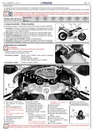
GENERAL INFORMATION 12) engine serial number 4) “limited series” number ★13) homologation data1) vehicle identification number1.4. Identification data1) vehicle identification number2) engine serial number3) homologation data4) “limited series” number ★Motorcycle identificationThe motorcycle is identified by the vehicle identificationnumber. When placing orders for spareparts, in addition to this number, you may berequired to provide the engine serial number andthe key identification.We recommend writing down the main numbersin the spaces provided below.FRAME No.:ENGINE No.:★ This motorcycle has been produced in a limitedseries. Each vehicle is identified by a serial numberstamped on a 24-carat gold plate.- 13 -
GENERAL INFORMATION 11Here below you can find a description of a vehicle identification number:ZCG F4 11 AC Y V 000000Manufacturer’s Letter CodeMotorcycle modelProgressive vehicle numberThe vehicle identification number must be provided each time you need to contact the <strong>MV</strong> <strong>Agusta</strong>Technical Assistance Service, in order to guarantee the traceability of your motorcycle.- 14 -
GENERAL INFORMATION 1Motorcycle key identificationA key is supplied in duplicate for both the ignition and allthe locks. Keep the duplicate in a safe place.It is essential to provide the key identification number ifyou place an order for a spare motorcycle key. Werecommend writing down this number in the space providedbelow:KEY No.:key identification number1- 15 -
GENERAL INFORMATION 1159 61011 12821834- 16 -
GENERAL INFORMATION 1Bodywork parts reference coloursBodywork parts are painted with the following reference colours:11. - Rear side fairing, right-hand;2. - Rear side fairing, left-hand;“Italia” Metal Clear Blue Painting(Code Palinal 928D264) +“Italia” Pastel Blue Painting(Code Palinal 929D263)8. - Front mudguard;9. - Fuel tank:“Italia” Metal Clear Blue Painting(Code Palinal 928D264) +“Italia” Pastel Blue Painting(Code Palinal 929D263)3. - Fuel tank right-hand side fairing;4. - Fuel tank left-hand side fairing;5. - Tail piece;6. - Air box side fairings;7. - Ignition switch cover:“Senna” Metal Matt Black Painting(Code Palinal 925XV414 +Palinal 923MAT.3)10. - Dashboard cover;11. - Right-hand rearview mirror;12. - Left-hand rearview mirror:“Senna” Metal Matt Black Painting(Code Palinal 925XV414 +Palinal 923MAT.3)- 17 -
GENERAL INFORMATION 1121108736495- 18 -
SAFETY INFORMATION 222.1. Safety2.1.1. NOTE ON TAMPERINGTampering with the noise control system is prohibited.In particular, the law prohibits the followingacts:1. The removal or rendering inoperative, otherthan for purposes of maintenance, repair, orreplacement, of any device or element ofdesign incorporated into any new vehicle for thepurpose of noise control prior to its sale or deliveryto the ultimate purchaser or while it is in use.2. The use of the vehicle after such device or elementof design has been removed or renderedinoperative.Acts presumed to constitute tampering include:1. The removal or piercing of the exhaustsilencer, the diaphragm, the manifolds, or anyother components involved in the transmissionof exhaust gases.2. The removal or piercing of any part of theintake system.3. Poor maintenance.4. The replacement of any movable parts of thevehicle or of any intake or exhaust componentswith parts or components other thanthose prescribed by the manufacturer.NOTEIf you notice a progressive increase of the noiselevel of your motorcycle, <strong>MV</strong> <strong>Agusta</strong> recommendsto have your noise control system controlled andif necessary replaced.Otherwise, riding with a defective muffler cansubject you to the penalties prescribed by stateand local provisions.- 20 -
SAFETY INFORMATION 22.1.2. SAFETY RULESIMPORTANT: READ BEFORE USEBefore riding, carefully read this manual so asto familiarize yourself with the controls, characteristics,working and limits of the motorcycle. Themanual is aimed at providing information on someof all the possible techniques and methods requiredfor safe riding.Do not attach a sidecar, a trailer or any otheraccessory to the motorcycle. Failure to observethis warning may make the vehicle unstable andcause serious accidents.To ensure maximum reliability and maintainthe vehicle in perfect working order, it is essentialto perform the servicing detailed in the ScheduledMaintenance Table and to follow all the instructionsprovided in this manual. For further information,speak with your dealer, who will have thenecessary technical skills and information to assistyou.<strong>MV</strong> <strong>Agusta</strong> continually strives to improve thequality of all of its motorcycles. Therefore, modificationsthat improve the performance of the bikeare made as soon as they are developed.Therefore, your motorcycle may not be describedexactly by the illustrations and text contained inthis manual.If you find difficulties in understanding any pictureor information contained in this manual, contactyour <strong>MV</strong> <strong>Agusta</strong> dealer to obtain the necessaryexplanations.If you find difficulties in reading any informationcontained in this manual, contact your <strong>MV</strong> <strong>Agusta</strong>dealer.In order to avoid compromising handling andstability of your motorcycle, you should obey thefollowing warnings:• do not attach any object to the vehicle;• do not remove any part and/or component;• do not modify the vehicle in any way;• do not wear garments that could adverselyaffect control and handling of the motorcycle.2- 21 -
SAFETY INFORMATION 22Do not ride this motorcycle if you do not possessa regular driving licence. Failure to heed thiswarning constitutes a breach of the HighwayCode, besides posing a serious hazard to the driver’sand other people’s safety.Do not try to service or repair this motorcycle ifyou do not possess the necessary skills.Motorcycle riding demands your completeattention. Do not ride if you are ill, in poor physicalcondition, or because of worry, etc., unable toconcentrate on the task at hand.Always wear a helmet, even on short rides.Always wear suitable clothes, especiallywhen travelling by night (e.g. garments withfluorescent bands).When refuelling, switch off the engine andrefrain from smoking.Since petrol is highly flammable, avoid spillingthe fuel onto the tank and the exhaust pipes whenrefuelling.When refuelling, stay away from the vehicle toavoid inhaling harmful fumes. Should the fuelcome into contact with the skin or clothes, immediatelywash with water and change the contaminatedgarments.When travelling during the day, use the lowbeam.Do not start the engine in closed places.Exhaust gases are toxic and can quickly saturatethe air and cause fainting or even death.Before starting the engine in a closed place,ensure that the area is well ventilated.While the vehicle is in motion, always rest thefeet on the specially designed supports.While riding, always keep both hands on thehandlebars.Do not cover your motorcycle with a canvassoon afterwards riding. Before covering yourmotorcycle, wait until the engine and the exhaustpipes have thoroughly cooled.- 22 -
SAFETY INFORMATION 2If your motorcycle has been involved in an accident, check all levers, wires, hoses, brake calipers andother main parts for damage. Do not use the vehicle if you detect a damage that could adversely affectsafety. Have all the main parts checked by an authorized <strong>MV</strong> <strong>Agusta</strong> dealer, in order to verify the absenceof defects and/or damages that the owner could not be able to detect.2.1.3. PRECAUTIONS FOR CHILDRENWARNING• Park the vehicle where it is unlikely tobe bumped into or damaged. Even slightor involuntary bumps can cause thevehicle to topple over, with subsequentrisk of serious harm to people or children.• To prevent the vehicle from tippingover, never park it on soft or unevenground, nor on asphalt strongly heatedby the sun.• Engine and exhaust pipes becomevery hot during riding. Always parkyour motorcycle where people or childrencan not easily reach these parts,in order to avoid serious burns.Parts at high temperature2- 23 -
SAFETY INFORMATION 222.1.4. INSTALLING ACCESSORIES<strong>MV</strong> <strong>Agusta</strong> provides a range of accessories speciallydesigned for your vehicle. It is essential thatthese accessories are installed by an <strong>MV</strong> <strong>Agusta</strong>dealer.WARNINGUse only <strong>MV</strong> <strong>Agusta</strong> original accessories.The use of non-genuine accessoriescan make the vehicle unsafe byreducing its handling, stability and theeffectiveness of the braking system. Forthis reason, the installation of any nongenuineaccessory makes the warrantynull and void and relieves <strong>MV</strong> <strong>Agusta</strong> ofall responsibility.Every time you apply accessories that affectthe weight and/or the aerodynamic characteristicsof your motorcycle, they must be assembled on itslower side and near to its center, as much as it ispossible. The brackets and the anchor bolts mustbe carefully checked after the assembling, toensure a stable framework and an unmovablesupport for the accessory. In fact, an eventualbreaking of these stands could cause dangeroussituations during riding.Verify that the assembling of the accessoriesdoes not cause a reduction of the minimum groundclearance and of the inclination of your motorcycle.Moreover, verify that the assembling of theaccessories does not cause any interference withthe handling of the steering system, with the travelof the suspensions and/or with the movement ofany other component involved in driving.Any accessory positioned on the handlebar oron the front fork can reduce the handling andadversely affect the stability of the vehicle.Therefore, the choice of the accessories shouldbe accurate and restricted to components of lightweight and small dimensions only.Your motorcycle could undergo lightening orother instability effects in case of wind blowing- 24 -
SAFETY INFORMATION 2sideways and transversely; this may also happenwhen your motorcycle runs into or it is overtakenby vehicles of great dimensions. Under these conditions,the accessories adversely affect your drivingsafety, especially if they are incorrectlyassembled or of the wrong type. It is thereforenecessary to pay great attention in choosing andassembling any accessory.Some accessories force the rider to drive in anunnatural position. This may obviously restrictyour freedom of movement and cause loss of controlof the vehicle.Additional electric accessories can cause anoverload of the electrical system of your motorcycle;this could damage the wires, causing dangerof short circuit and electric shock.2.1.5. VEHICLE LOADYour motorcycle is designed for use by the riderand it can also seat a passenger. To use the vehiclein complete safety and in accordance with theHighway Code provisions, it is compulsory thatthe following maximum load conditions are neverexceeded:BRUTALE 910 Italia370 kgThis value comes out from the sum of the followingweights, according to the European standardCEE 92/61:• weight of the motorcycle;• weight of the driver;• weight of the passenger;• weight of the load and all the accessories.2- 25 -
SAFETY INFORMATION 22WARNINGSince the load can strongly affect handling,braking, performance and safetycharacteristics of your motorcycle, youshould always keep in mind the followingwarnings.• NEVER OVERLOAD YOUR MOTOR-CYCLE! Driving an overloaded motorcyclecan cause damage to the tyres, loss ofcontrol of the vehicle and serious injury.Verify that the total weight (including theweight of the motorcycle, the driver, thepassenger, the load and all the accessories)does not exceed the maximum loadvalues specified for your vehicle.• Before riding, always check the wearand the pressure of the tyres.• Never carry any incorrectly fastenedobject on your motorcycle, because itcould move from its position duringriding.• Steadily fasten the heaviest objectsnear the center of the motorcycle, andequally divide the load on both sides ofthe vehicle.• Do not insert any object or accessoryin the spaces on the frame trellis, inorder to avoid interferring with themovable parts of the motorcycle.• Adjust the suspensions according tothe load.• Even if the motorcycle is correctlyloaded, drive with caution and neverexceed 130 km/h when you carry a load.- 26 -
SAFETY INFORMATION 22.1.6. MODIFICATIONS<strong>MV</strong> <strong>Agusta</strong> suggests neither to remove any originaldevice, nor to modify the motorcycle in anyway that could change its shape or its working.WARNINGAny modifications made to the vehicle(e.g. alteration and/or removal of components)can make the vehicle unsafe orunlawful. <strong>MV</strong> <strong>Agusta</strong> cannot be heldresponsible for any damage to peopleand objects subsequent to eventualmodifications made to the original conditionsof your motorcycle. Modifyingthe vehicle immediately voids the warrantyand relieves <strong>MV</strong> <strong>Agusta</strong> of allresponsibility.2.1.7. COMPETITIONSWARNING: Riding the vehicle in competitionsrequires considerable skill andexperience as well as an accurate setupof the motorcycle.CAUTION: The high temperaturescaused by the use of the vehicle on racecircuits could compromise the efficiencyof the catalytic converter and of theexhaust system; therefore, we suggestassembling a special exhaust systemwhen using the vehicle on race circuits.<strong>MV</strong> <strong>Agusta</strong> has designed a number of specialcomponents for use in competitions and/or sportingevents. The use of such components is strictlylimited to areas closed to traffic. Failure toobserve this restriction constitutes a breach of theHighway Code for which <strong>MV</strong> <strong>Agusta</strong> cannot beheld responsible.2- 27 -
SAFETY INFORMATION 222.1.8. RECOMMENDATIONS FOR SAFE RID-INGBesides being a means of transport, your motorcycleis a source of recreation and excitement.However, the configuration of the vehicle does notexclude a certain amount of risk. To ensure maximumsafety, in addition to scrupulously observingthe warnings and instructions provided in the previousparagraphs, it is essential to take a fewadditional precautions.In particular:Before starting offFollow all the directions given in the section “PRE-RIDING CHECKS”. Conduct an overall check ofall safety-related aspects of the motorcycle.Familiarizing with the vehicleThe rider’s ability and his mechanical skills formthe basis of riding safety. It is advisable to practiseriding in areas without traffic until you havebecome familiar with the vehicle and its controls.Being aware of one’s limitsWhen riding, never exceed your limits nor thoseimposed by law. Being aware of your limits andacting accordingly will help you avoid accidents.Adverse weather conditionsBe very careful when riding in adverse weatherconditions. On wet roads, for example, the brakingdistance increases as a result of reduced tyretraction. It is therefore necessary to travel at moderatespeed and avoid abrupt braking and acceleration.Pay particular attention when riding onslippery surfaces such as road markings, manholes,level crossings, bridges, gratings, etc.Considering that a motorcycle cannot provide thesame degree of shock protection as a motor vehicle,it is essential to adopt a “defensive” riding attitude,particularly in the adverse weather conditionsdescribed above.- 28 -
SAFETY INFORMATION 2Keeping even one foot or hand away from theirdesigned supports could cause loss of control ofthe vehicle and increase the risk of accidents.Always keep both hands on the handlebars andboth feet on the footrests during riding.Change gears as necessary to ensure that theproper gear ratio is chosen in all riding conditions,allowing the engine to run at optimum speed at alltimes. Avoid high gear ratios when travelling atreduced speed (excessively low rpm) as well aslow gear ratios when travelling at high speed(excessively high rpm).Always operate the clutch system when youchange gear, in order to avoid damage of theengine, of the gearbox and of the transmission.These components have not been designed totake the shocking stress caused by the forcedcoupling of a gear.Do not keep the clutch disengaged for a longtime during riding, unless you have to changegear. Failure to heed this warning may lead to theoverheating and to the abnormal wear of the clutchcomponents.When rapid acceleration is required (e.g. whenpassing), select a lower gear to obtain betteracceleration.When the motorcycle is being ridden at highspeed, gearing down several times in rapid successioncan cause the engine to overspeed. As aresult, the rear wheel may lock, causing loss ofcontrol of the vehicle, as well as damage to theengine and transmission.When riding down long hills, reduce the speedof your motorcycle by closing the throttle andusing a low gear ratio to take advantage of enginebraking. Use the front and rear brakes as littleas possible to maintain your speed, in order toprevent brake overheating and fade.Special attention should be given to the brakingsystem, which plays a key role in ensuring safety.When braking, always take account of the speed ofthe vehicle and the condition of the road surface.2- 29 -
SAFETY INFORMATION 22The braking action should always be applied gentlyand gradually to both wheels.Performing this operation and, more in general,riding the vehicle always requires the utmost care.Therefore, caution should be exercised by allusers, and in particular by inexperienced riders.When you make a turn, avoid sudden braking.Failure to observe this warning could lead to thesliding of the wheels and the loss of control of thevehicle. Always operate the brakes before startinga turn.When you are laterally blown by a sudden gustof wind (as it may happen when you’re overtakenby a vehicle of great dimensions, when you comeout of a tunnel or when you’re driving in a hillyzone), you could lose control of the vehicle. Whiledriving under the above mentioned conditions,reduce your speed and be careful to avoidsideways gusts of wind.Maintain a safe distance behind vehicles infront of you and adjust your speed to the weatherand traffic conditions. Remember that, as yourbike picks up speed, stopping distances increaseand the motorcycle becomes more difficult to control.In any case, never exceed the speed limitsimposed by the Highway Code.When travelling during the day, keep the lowbeam on in order to be better seen by other roadusers.It is strictly forbidden to drink alcoholic beveragesor take drugs before riding. Even very smallamounts of these substances adversely affect therider’s ability to control the vehicle.- 30 -
SAFETY INFORMATION 22.1.9. PROTECTIVE CLOTHINGHelmet wearing is compulsory under the HighwayCode. Helmet is the most important part in thebiker’s protective clothing, because it protects himfrom head injury in the event of an accident.Always fasten your helmet properly and securely.If you wear an open-face helmet, also wear goggles.Without a protective shield, in fact, windracing on your face during driving could reduceyour visual capacity, increasing the risk of accidents.WARNING: Failure to wear a helmetincreases the risk of serious injury oreven death in the event of an accident.Make sure that you and your passengeralways wear an approved helmet duringdriving. If you wear an open-face helmet,also wear protective glasses.Always wear suitable protective clothing. In particular,the following items should be worn:A close fitting jacket, made of tough materialand easy to fasten.Supple, reinforced gloves providing both sensitivityand protection.Strong, close-fitting trousers covering the legscompletely.Soft, reinforced boots providing both sensitivityand protection.The items mentioned above are available fromany specialized shop.We recommend buying brightly coloured clothes,as they make the rider easier to see at night andin the fog.In any case, the clothes must allow complete freedomof movement and not hamper the rider in anyway. In addition, they must have no loose partscapable of catching in the control levers, thefootrests, the wheels, the drive chain, etc., inorder to avoid dangerous situations.2- 31 -
SAFETY INFORMATION 22WARNINGProtective clothes do not afford completeprotection against the risk of personalinjury in the event of an accident.It is therefore essential not be deceivedby the false sense of security that youmight perceive by wearing protectiveclothing. When riding, always adopt acautious attitude and follow the recommendationsgiven in the previous paragraphs.2.1.10. SUGGESTIONS AGAINST THEFT1. Every time you park your motorcycle, operatethe steering lock and remove the ignition key(see § 3.5.).2. Park your motorcycle in a closed garage everytime it is possible.3. Install a good quality anti-theft device on yourvehicle.4. Always keep up to date the registration data ofyour motorcycle.5. Write down your name, address and phonenumber in the spaces provided down below,and always keep this use and maintenancemanual inside the glove compartment of yourmotorcycle (see § 4.6.). This is very important,because a stolen motorcycle can be subsequentlyidentified by reading the informationswritten in the manual found inside it.NAME:ADDRESS:PHONE NUMBER:- 32 -
SAFETY INFORMATION 22.2. Safety Labels - Location3 1 21 - Unleaded petrol2 - Battery warning3 - Tyre pressure4 - Rear wheel hub warning5 - Chain adjustment2NOTEThe labels in the following pagesdo not appear in their real size. Ifyou find difficulties in understandingany of these labels,contact an authorized <strong>MV</strong> <strong>Agusta</strong>dealer.54- 33 -
SAFETY INFORMATION 21. ADHESIVE LABEL –UNLEADED PETROL22. ADHESIVE LABEL –BATTERY WARNING- 34 -
SAFETY INFORMATION 23. ADHESIVE LABEL –TYRE PRESSURE24. ADHESIVE LABEL –REAR WHEEL HUBWARNING- 35 -
SAFETY INFORMATION 25. ADHESIVE LABEL –CHAIN ADJUSTMENT2- 36 -
SAFETY INFORMATION 22.3. Safety - Visual and acoustic signalsBefore each ride, it is essential to verify the operation of the visual and acoustic signals.Parking light, low and high beams (§ 3.3)Parking light (§ 3.3) and brake lightTurn indicators (§ 3.3)(lights up operating the brakes)2Horn (§ 3.3)Turn indicators (§ 3.3)Plate light (lights up when parkinglights are turned on)- 37 -
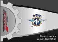
CONTROLS AND INSTRUMENTS 33.1. Location of controls and instrumentsHandlebar electrical controls, left side (§ 3.3)Instruments and warning lights (§ 3.7)Ignition switch and steering lock (§ 3.5)3Left sideFuel tank cap (§ 4.5)Right sideHandlebar electrical controls, right side (§ 3.4)Throttle twist grip (§ 3.4)- 38 -
CONTROLS AND INSTRUMENTS 3Front brake lever (§5.1.)Clutch lever (§5.1.)Rearview mirrors (§5.1.)Passenger footrestPassenger footrestPassenger handhold3Passenger handholdRear brake lever (§5.1.)Rider footrest (§5.1.)Rider footrest (§5.1.)Gear lever (§3.6. and §5.1.) Sidestand (§3.2.)- 39 -
CONTROLS AND INSTRUMENTS 33.2. Sidestand3The sidestand is equipped with asafety switch that prevents themotorcycle from moving off while thestand is down.If the rider attempts to engage thegears while the engine is running andthe stand is down, the switch automaticallyturns off the engine by cuttingthe current supply.If the motorcycle is parked (sidestanddown) and the gears areengaged, the switch prevents theengine from being started, therebyavoiding the risk of accidentally topplingthe vehicle.Safety switchSidestandSidestandDual return spring- 40 -
CONTROLS AND INSTRUMENTS 33.3. Handlebar controls, left sideClutch leverMove towards/away from the handgrip torelease/engage the clutch.3High beam flasher buttonPress the button repeatedly.Low/high beam buttonButton not pressed inButton pressed in: low beam: high beamHorn buttonPress to operate the warning horn.- 41 -Turn indicator switchShifting the lever to the left or right switches on the leftor right turn indicators. The switch then returns to thecentral position. Press to turn off the indicators.
CONTROLS AND INSTRUMENTS 3High beam flasher buttonIt is used to attract the attention of other road users in case of danger. When the high beam is on, thefunction is inactive.3Low/high beam buttonUnder normal conditions, the low beam is on. The high beam can be switched on by pressing the buttonwhen allowed by the traffic and road conditions.Turn indicator switchIt is used to show the rider’s intention to change direction or lane.WARNINGFailure to switch the turn indicators on or off at the right time may cause an accident in thatthe other road users may draw incorrect conclusions about the direction of motion of thevehicle. Always switch on the indicators before turning or changing lanes. Then be sure toswitch off the indicators after completing the operation.Horn buttonIt is used to attract the attention of other road users in case of danger.Clutch leverIt engages/disengages the clutch through a hydraulically controlled device.- 42 -
CONTROLS AND INSTRUMENTS 33.4. Handlebar controls, right sideFront brake leverPull to the lever to apply the front brake.Throttle twist gripRotate counterclockwise to increase engine speed.3Cold start (choke) leverRotate clockwise when cold starting. After the engine has run fora few seconds, return the lever to its original position.Engine stop switchStops the engine and prevents it from being restarted.Engine start buttonStarts the engine. To be released as soon as the engine starts.When the engine is running, pressing the button selects the displayfunctions.- 43 -
CONTROLS AND INSTRUMENTS 3Engine stop switchIt is used to switch off the engine in an emergency. The ignition circuit is disabled, preventing the enginefrom being restarted. To be able to restart the engine, return the switch to its original position.3NOTEUnder normal conditions, do not use this switch to shut off the engine.Engine start buttonIt is used to start the engine and, when the engine is running, to select the different functions of the displayinstalled on the instrument panel.CAUTIONTo avoid damaging the electrical equipment, be sure not to hold down the button for longerthan 5 consecutive seconds.If, after some attempts, the engine does not start, refer to the chapter “TROUBLESHOOT-ING” later in this manual.Cold start (choke) leverIt facilitates cold starting by slightly enrichening the fuel-air mixture during start-up.NOTEThis function must remain active only for a short time depending on the engine and environmentaltemperature. As soon as the idle speed keeps the engine running, it is advisable to disablethe control.- 44 -
CONTROLS AND INSTRUMENTS 3Throttle twist gripIt controls the fuel-air mixture supplied to the engine, which regulates engine speed. To increase enginespeed, rotate the hand grip from its idle position counterclockwise.When cold starting (choke on), rotating the throttle twist grip clockwise fully causes the choke lever toreturn to its original position.Front brake leverIt controls a hydraulic circuit that operates the front wheel braking system.3- 45 -
CONTROLS AND INSTRUMENTS 33.5. Ignition switch and steering lockWARNINGDo not attach a ring or any other object to the ignition key as they may hinder the steering action.3WARNINGNever attempt to change the switch functions while riding, as you may lose control of the vehicle.Ignition switch and steering lockON PositionOFF PositionLOCK PositionP (Parking) Position- 46 -
CONTROLS AND INSTRUMENTS 3The ignition switch enables and disables the electrical circuit and the steering lock. The four positions ofthe switch are described below.OFF positionAll electrical circuits are deactivated. The key canbe removed.ON positionAll electrical circuits are activated. The instrumentsand warning lights perform the self-diagnosticcycle. The engine can be started. The keycannot be removed.3CAUTION: Do not leave the key on the ON position for a long time when the engine is notrunning, in order to avoid damage to the electrical parts of the motorcycle.- 47 -
CONTROLS AND INSTRUMENTS 3LOCK position3Turn the handlebar to the left. Press the key ingently while rotating it to the LOCK position.All electrical circuits are deactivated and thesteering is locked. The key can be removed.Left sideRight side- 48 -
CONTROLS AND INSTRUMENTS 3P (PARKING) positionTurn the key from the LOCK position to the Pposition. All electrical circuits are deactivatedexcept the parking lights. The steering is locked.The key can be removed.CAUTIONDo not leave the key on the P positionfor a long time, in order to avoiddischarging the battery of yourmotorcycle.3- 49 -
CONTROLS AND INSTRUMENTS 33.6. Gear lever3The N (neutral) position is indicated by the warning light on the instrument panel.To change into first gear, push the lever down.To change into second gear, lift the lever up. Lifting the lever up repeatedly engages all the other gearsin succession up to the sixth speed.6 th5 th4 th3 rd2 ndN1 stGear lever- 50 -
CONTROLS AND INSTRUMENTS 33.7. Instruments and warning lightsThe instruments and warning lights are activated by turning the ignition switchto the ON position. After a preliminary check (approx. 7 seconds) the displayedinformation reflects the current general condition of the motorcycle.Warning lights(§3.7.1.)3SET button (§3.7.2.)Warning light(§3.7.1.)Multifunction display (§3.7.2.)Tachometer- 51 -
CONTROLS AND INSTRUMENTS 333.7.1. Warning lightsHigh beam warning light (blue)Lights up when the high beam is activated.Low beam warning light(green)Comes on when the low beamis activated.Neutral indicator (green)Lights up when the gears are inneutral.Turn indicator light (green)Lights up when the turn indicatorsare activated.Reserve fuel indicator (amber)Comes on when approximately4 litres of fuel are left.Battery charge indicator (red)Lights up when the alternator does not supply enoughcurrent to charge the battery.If the indicator comes on whileriding, contact an authorized servicecentre.Sidestand down warning light(red)Lights up when the sidestand isdown.Rev limiter warning light (red)Lights up when the engine speedexceeds 11,300 rpm. The revlimiter limits the rpm to 12,000.Engine oil pressure warning light (red)Lights up when the oil pressure is insufficient.WARNING: If the warning light comes on whileriding, stop the motorcycle immediately. Checkand if necessary restore the oil level. If the warninglight comes on even if the oil level is correct,do not resume riding and contact an authorizedservice centre.- 52 -
CONTROLS AND INSTRUMENTS 33.7.2. Multifunction displaySpeedometerMeasures the speed of the vehicle. The speedcan be displayed in kilometres per hour (km/h)or miles per hour (mph). The full-scale value is299 km/h (186 mph).SET buttonPressing the button allows thesetting of the different displayfunctions. Pressing the buttonagain confirms the entered values.TOTAL mileage counterDisplays the total distance covered: from 0 to 99,999.9(km or mi)TRIP 1 mileage counterDisplays a first trip mileage count: from 0 to 9,999.9 (km or mi)TRIP 2 mileage counterDisplays a second trip mileage count: from 0 to 9,999.9(km or mi)ClockDisplays the time (0÷24)- 53 -ThermometerDisplays the coolant temperature in degrees centigrade(°C) or Fahrenheit (°F).The display range is 40° to 140° C (104° to 284° F):- Below 40° C (104° F) no temperature is displayed butthree blinking lines denote a verylow temperature.- Between 40° and 49° C (104°and 120° F) the temperature readingblinks to indicate a low temperature.- Between 50° and 111° C (122°and 232° F) the temperature readingis fixed.- Between 112° and 140° C (234°and 284° F) the temperature readingblinks to indicate a high temperature.WARNING: If the temperature exceeds 120° C (248°F), stop the motorcycle immediately and check thecoolant level. If the coolant level is low, carefully topup the coolant, after you have allowed the engine tothoroughly cool. Never attempt to remove the coolantfiller cap when the engine is hot. If the high temperatureindication is given even when the coolant level iscorrect, do not resume riding and contact an authorizedservice centre (see chapter 7 “Troubleshooting”).3
OPERATION 444.1. Using the motorcycleThis section provides the basic information needed to correctly operate the motorcycle:– Running-in ( § 4.2 )– Starting the engine ( § 4.3 )– Selecting and setting the display functions ( § 4.4 )– Refuelling ( § 4.5 )– Glove compartment ( § 4.6 )– Parking the motorcycle ( § 4.7 )– Preriding checks ( § 4.8 )– Riding ( § 4.9 )WARNING: The F4 BRUTALE 910 Italia motorcycle shows high power and performancecharacteristics; therefore, its use requires an adequate level of knowledge of the vehicle.When you use this motorcycle for the first time, it is essential to adopt a cautious attitude.An aggressive or reckless riding attitude can lead to accidents, compromising the driver’sand other people’s safety.CAUTION: The high temperatures caused by the use of the vehicle on race circuits couldcompromise the efficiency of the catalytic converter and of the exhaust system; therefore,we suggest assembling a special exhaust system when using the vehicle on race circuits.Respect and defend natural environmentEverything we do affects the whole planet as well as its resources.<strong>MV</strong> <strong>Agusta</strong>, in order to protect the interests of the community, awakens the Customers and the Technical Assistance operatorsto use the vehicle and dispose of its replaced parts respecting the laws in force concerning environmental pollution andwaste disposal and recycling.- 54 -
OPERATION 44.2 Running-inCAUTIONFailure to observe the indications providedbelow can reduce performance and shortenthe life of the motorcycle.Running-in is generally considered to apply only to theengine. In fact, it should be regarded as an essentialphase for other important parts such as the tyres, thebrakes and the drive chain. During the very first miles,adopt a relaxed riding style.❏ 0 to 500 km (0 to 300 mi) (A)Frequently change the engine speed. If possible, preferhilly routes with gentle slopes and many bends. Avoidlong straight stretches.- 55 -MAX5500-6000 rpmWARNINGNew tyres must undergo a properrunning-in period to reach theircomplete efficiency. Avoid abruptacceleration, turning and brakingduring the first 100 km. Failure toobserve these prescriptions canlead to the sliding of the wheelsand the loss of control of the vehiclewith subsequent risk of accidents.4
OPERATION 4❏ 500 to 1000 km (300 to 600 mi)Avoid lugging or overspeeding the engine, and varyyour speed frequently.MAX8000-9000 rpm4❏ 1000 to 2500 km (600 to 1600 mi)Higher engine performance can be demanded, but it isadvisable not to exceed the engine speed shown in thefigure.MAX11000 rpm- 56 -
OPERATION 44.3. Starting the engineWARNINGStarting the engine in a closed place can bedangerous. Exhaust emissions contain carbonmonoxide, a colourless and odourlessgas that can lead to serious harm or evendeath when inhaled.Only start the engine outdoor, in the open air.As you turn the ignition switch to the ON position, theinstruments and the warning lights will go through theself-diagnostic cycle; during this phase, make sure thatall the warning lights on the dashboard come on. One ofthe following conditions must be verified, in order that theignition switch system allows engine starting:– The gears are in neutral.– The gears are engaged, the clutch lever is pulledand the side stand is up.❏ Cold startingRotate the CHOKE lever without turning the throttletwist grip and then press the start button.- 57 -CHOKE lever4
OPERATION 4As soon as the engine starts, release the button and,after warming up the engine for a short time, return theCHOKE lever to its original position.4❏ Hot startingPress the start button without turning the throttletwist grip.As soon as the engine starts, release the button.CAUTION• Do not press the start button for longer than5 consecutive seconds, in order to avoid damageto the electrical equipment.• Avoid warming up the engine while the vehicleis stationary. The subsequent engine overheatingcan cause damage to the internalparts of the engine. It is advisable to bring theengine to the working temperature by ridingat reduced speed.• To ensure the maximum life of the engine,never speed up at full throttle when the engineis cold.- 58 -
OPERATION 44.4. Selecting and setting the display functionsThe display functions allow to change some of themain measuring parameters.The possible operations are listed as follows:- Selecting the functions:TOTAL Mileage CounterTRIP 1 Mileage CounterTRIP 2 Mileage CounterClock- Setting the following measurement units:SpeedMileageTemperature- Resetting the trip mileage counters:TRIP 1 Mileage CounterTRIP 2 Mileage Counter- Setting the clock.4- 59 -
OPERATION 444.4.1. Selecting the display functionsYou can select the following functions:• TOTAL Mileage Counter• TRIP 1 Mileage Counter• TRIP 2 Mileage Counter• ClockThe TOTAL, TRIP 1 and TRIP 2functions can be displayed by pressingthe engine start button. Pressingthe button repeatedly cycles throughthe different functions. Select thedesired function.WARNINGThe operation must be performed while the engine isrunning, the gears are in neutral, the motorcycle isstationary, and with the feet on the ground. Do not setthe display functions while riding as it may causeloss of control of the vehicle.- 60 -
OPERATION 44.4.2. Setting the measurement unitsIt is possible to set the measurement units of thedisplayed quantities.WARNINGThe operation must be performed while theengine is running, the gears are in neutral, themotorcycle is stationary, and with the feet onthe ground. Do not set the display functionswhile riding as it may cause loss of control ofthe vehicle.4❏ Speedometer (Km/h - Mph)Repeatedly press the engine start button until theTOTAL mileage counter is displayed.Press the SET button; the speedometer unit startsblinking.- 61 -
OPERATION 4Press the engine start button to toggle betweenKm/h and Mph. Changing the speedometer unit alsochanges the units for the total and trip mileage counters.Remember that:1 mi = 1,609 Km4Press the SET button to confirm the speedometerunit. The thermometer unit will start blinking, indicatingthat the display is ready for the next setting.- 62 -
OPERATION 4❏ Thermometer (° C - ° F)Press the engine start button to toggle between ° Cand ° F.Remember that: T (°F) = 1.8 • t (°C) + 324Press SET to confirm the temperature unit.- 63 -
OPERATION 44.4.3. Resetting the trip mileage countersThe TRIP 1 and TRIP 2 counters can be reset as follows:4WARNINGThe operation must be performed while theengine is running, the gears are in neutral, themotorcycle is stationary, and with the feet onthe ground. Do not set the display functionswhile riding as it may cause loss of control ofthe vehicle.Select the TRIP 1 function by pressing the enginestart button.Press the button for longer than four seconds. TheTRIP 1 mileage will start blinking.- 64 -
OPERATION 4Pressing the button for less than four seconds setsthe mileage to zero. If, on the other hand, the button ispressed for longer than four seconds the entire resettingprocedure is cancelled.4Select the TRIP 2 function by pressing the enginestart button.- 65 -
OPERATION 4Press the engine start button for longer than fourseconds; the TRIP 2 mileage will start blinking.4Pressing the button for less than four seconds setsthe mileage to zero. If, on the other hand, the button ispressed for longer than four seconds the entire resettingprocedure is cancelled.- 66 -
OPERATION 44.4.4. Setting the clockIt is possible to set the clock function.WARNINGThe operation must be performed while theengine is running, the gears are in neutral, themotorcycle is stationary, and with the feet onthe ground. Do not set the display functionswhile riding as it may cause loss of control ofthe vehicle.4Repeatedly press the engine start button until thetime is displayed.Press the SET button – the first hour digit will startblinking.- 67 -
OPERATION 4Hold down the engine start button and release it assoon as the desired figure is displayed.NOTETo quickly cycle through the selected digit, hold thestart button depressed for longer than two seconds.4Press SET to confirm the first hour digit and to beable to set the following digit.Repeat the procedure to set the second hour digitand the first and second minute digits.Press SET to confirm the time and exit the set(blinking) mode.NOTEThe instrument panel has an integrated memorywhich retains all the parameters even when the engineis not running. Except for the clock, which isreset, all the parameters are retained even when thebattery is disconnected.- 68 -
OPERATION 44.5. RefuellingWARNINGPetrol and its fumes are highly toxic and flammable.Avoid contact and inhalation.When refuelling, switch off the engine, avoidsmoking, and keep away from flames, sparksand heat sources. Perform refuelling in theopen air or in a well ventilated area.CAUTIONOnly use unleaded fuel with a R.O.N. octanerating of 95 or higher. The green dot on thelower side of the tank cap serves as a reminderof this.4Lift the dust cover.Insert the key into the lock and rotate it clockwise.- 69 -
OPERATION 4Lift the tank cap and operate the refuelling.4WARNINGOverfilling the tank may cause the fuel tooverflow as a result of the expansion due tothe heat from the engine or to exposure tosunlight. Fuel spills can catch fire. The levelof the fuel in the tank must never be higherthan the base of the filler.After refuelling, press down the tank cap while rotatingthe key clockwise to facilitate the locking. Thenrelease the key and remove it.CAUTIONImmediately wipe the overflown fuel with aclean cloth, to avoid damage to the painted orplastic surfaces.WARNINGVerify that the tank filler cap is correctly closedbefore using the motorcycle.- 70 -
OPERATION 44.6. Glove compartmentInsert the key into the lock.4Press down the pillion while turning the keyclockwise. Lift the pillion.- 71 -
OPERATION 4Remove the pillion.In order to reassemble the above mentioned part,you must perform the following operations:4• Rotate the key into the lock• Press down the pillion• Release the key• Press down the pillion once more, so tomake sure of its firm coupling to theframe.WARNINGEvery time you lift or remove the pillionand every time the vehicle is used, makesure that the above mentioned part iscorrectly placed and that it is firmlysecured to the motorcycle framework.- 72 -
OPERATION 44.7. Parking the motorcycle❑ Using the sidestandCAUTIONPark the motorcycle safely on solid ground.On slopes, engage the first gear and parkthe vehicle so that the front wheel facesuphill. Remember to put the gear lever in theneutral position before restarting the engine.Never leave the vehicle unattendedwhile the engine key is in the dashboard.Do not sit on the vehicle when it is parkedon the sidestand, as your full weight wouldrest on the vehicle’s only support. Beforeriding off, ensure that the sidestand warninglight on the instrument panel goes out.In any case, make sure that the stand hasbeen retracted. If you notice a malfunctionof the side stand switch, have it controlledby your <strong>MV</strong> <strong>Agusta</strong> dealer before using themotorcycle.Using your foot, lower the sidestand as far as it will go, and then slowly tip the motorcycle toward youto bring the stand supporting foot into contact with the ground’s surface.4- 73 -
OPERATION 44❏ Using the rear standInsert the stand pin into the rear wheelaxle hole on the left side of the motorcycle.Rest the stand on the ground and,pressing down on the stand, lift the vehicleuntil it reaches a stable condition.CAUTIONThis operation is best carriedout with two people, one tosteady the motorcycle and oneto manipulate the rear stand.1 23- 74 -
OPERATION 44.8. Preriding checksWARNINGA motorcycle can be in good runningorder and then become unexpectedlyunreliable even if unused (e.g. deflationof the tyres). It is therefore important tocarry out the checks described in thetable below before each ride. A fewmoments taken to carry out these checkswill help you maintain your motorcyclesafe and in perfect working order.BrakesCheck fluid level (§6.7).Check for fluid leakage.Pull lever and press pedal to check brake operation.Lubricate the lever joint, if necessary.Check pads for wear (§6.6).Gear leverPress pedal to check gear operation.Lubricate the lever joint, if necessary.Clutch leverCheck fluid level (§6.8).Check for fluid leakage.Pull lever and check that it moves smoothly and gradually.Lubricate the lever joint, if necessary.Engine start button / stop switchCheck operation (§3.4).Throttle twist gripCheck that grip rotates smoothly and returns to closedposition when released.Steering systemVerify that the operation is smooth and uniform.Check for play and loosening.Lights, visual and acoustic signalsCheck operation.TyresCheck inflating pressure and wear (§6.9).SuspensionsVerify that the operation is smooth and uniform.Check adjustment (§5.6 and 5.7).Frame fastenersCheck tightening of all screws and nuts.Tighten them, if necessary.Drive chainCheck adjustment and lubrication (§6.10).CoolantCheck level (§6.5).Check for leakage.4- 75 -
OPERATION 44FuelCheck level.Refuel, if necessary (§4.5).Check for fuel leakage.Engine oilCheck level (§6.4).Check for leakage.SidestandCheck return to stowed position.Verifiy that the safety switch is working.PillionVerify that the pillion is firmly secured to the framework.WARNINGIf any of the above-mentioned partsshows a failure during its operation,have it controlled and repaired beforeusing the motorcycle.- 76 -
OPERATION 44.9. RidingRiding a motorcycle requires experience and concentration.Inexperienced riders should undergo a period of training and attend an introductory course consisting oftheoretical lessons as well as practical riding sessions in areas closed to traffic.The instructor’s advice will help the novice rider become familiar with the basics of riding safety.Relying on the advice of persons other than a qualified riding instructor, even if possessing specificknowledge, may prove to be useless or even dangerous, especially if the practical training takes placein an area open to traffic.WARNINGWhile riding, always observe the safety prescriptions described in paragraph 2.1.8. of thismanual.4- 77 -
ADJUSTMENTS 55.1. List of adjustmentsThere are many adjustments that can significantlyimprove the ergonomics, geometry and safety of themotorcycle.Some of these can only be performed by skilled personnelat authorized service centres.5WARNINGTo avoid losing control of the vehicle whileriding, be sure to always keep both handson the handlebars. All adjustments must beperformed when the vehicle is stationary.- 78 -
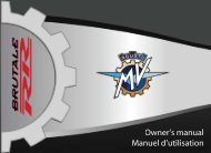
ADJUSTMENTS 5(F) Rearview mirror adjustment (§5.5.)(A) Front brake lever adjustment (§5.3.)(G) Front suspensionadjustment (§5.6)(C) Right-hand footrestadjustment (§5.2.)(M) Headlightadjustment (§5.8.)(H) Rear suspensionadjustment (§5.7.)5(E) Rear brake leveradjustment (§5.2.)(G) Front suspensionadjustment (§5.6)- 79 -
ADJUSTMENTS 5(F) Rearview mirror adjustment (§5.5.)(H) Rear suspension adjustment (§5.7.)(B) Clutch leveradjustment (§5.4.)5(D) Gear leveradjustment (§5.2.)(C) Left-hand footrest adjustment (§5.2.)(L) Drive chainadjustment (§6.10.)- 80 -
ADJUSTMENTS 55.2. List of adjustmentsA - Front brake lever adjustment: Optimizesthe grip to suit the rider’s needs (§5.3).B - Clutch lever adjustment: Optimizes the gripto suit the rider’s needs (§5.4).C - LH and RH footrest adjustment: Optimizesthe position of the feet to suit the rider’s needs.D - Gear lever adjustment: Optimizes the positionof the lever to suit the rider’s needs.E - Rear brake lever adjustment: Optimizes theposition of the lever to suit the rider’s needs.F - Rearview mirror adjustment: Optimizes theorientation of the rearview mirrors (§5.5).WARNING: Do not operate the screwfixing the rearview mirror to the handlebar.If this screw needs to be tightened,contact your <strong>MV</strong> <strong>Agusta</strong> dealer.- 81 -G - Front suspension adjustment: The followingcan be adjusted to adapt the response ofthe suspension to the rider’s preference:- spring preload (§5.6.1.)- rebound damper (§5.6.2.)- compression damper (§5.6.3.)H - Rear suspension adjustment: The followingcan be adjusted to adapt the response of thesuspension to the rider’s preference:- spring preload- geometry height- rebound damper (§5.7.1.)- high speed compression damper (§5.7.2.)- low speed compression damper (§5.7.3.)L - Drive chain adjustment: To ensure safe andeffective transmission of power.M - Headlight adjustment: To adjust the range ofthe light beam to the geometry of the motorcycle(§5.8).5
ADJUSTMENTS 55.3. Adjusting the front brake leverWARNINGNever perform the adjustment whileriding.While pulling the lever to counter the action of thespring, turn the ring clockwise or counterclockwiseto move the lever away or towards the handgriprespectively.5.4. Adjusting the clutch leverWARNINGNever perform the adjustment whileriding.While pulling the lever to counter the action of thespring, turn the ring clockwise or counterclockwiseto move the lever away or towards the handgriprespectively.5- 82 -
ADJUSTMENTS 55.5. Adjusting the rearview mirrorsWARNINGNever perform the adjustment while riding.Press the mirror at the points shown in the figure toadjust its position in the four directions.Perform the adjustment on both the rearview mirrors. Itis recommended to sit on the vehicle in order to optimizethe rearview mirrors adjustment.WARNING: Check the rearview mirrors adjustmentevery time you use your motorcycle.5- 83 -
ADJUSTMENTS 55.6. Adjusting the front suspensionWARNINGIt is essential that the adjusters ofboth fork rods are adjusted to thesame position.Rebound damperSpring preload5Compression damper- 84 -
ADJUSTMENTS 55.6.1. Spring preloadThe adjustment is obtained from the standardposition, which is found by fully turning the adjustingnut counterclockwise and then clockwise(see enclosed table). Rotate clockwise to increasethe spring preload or counterclockwise todecrease it.5.6.2. Rebound damper (front suspension)The adjustment is obtained from the standardposition, which is found by fully turning the screwclockwise and then counterclockwise (see enclosedtable). Rotate clockwise to increase the dampingaction or counterclockwise to decrease it.CLICK!CLICK!CLICK!5- 85 -
ADJUSTMENTS 55.6.3. Compression damper (front suspension)The adjustment is obtained from the standard position,which is found by fully turning the screw clockwise andthen counterclockwise (see enclosed table). Rotateclockwise to increase the damping action or counterclockwiseto decrease it.CLICK!CLICK!CLICK!5- 86 -
ADJUSTMENTS 55.7. Adjusting the rear suspensionWARNINGThe high temperature of the exhaust pipes can cause burns. Before adjusting the rear suspension,shut off the engine and wait until the exhaust pipes have thoroughly cooled.High and Low speedcompression damper5Rebound damper- 87 -
ADJUSTMENTS 55.7.1. Rebound damper (rear suspension)The adjustment can be performed by operating on the screw placed on the lower side of the shock absorber,and it is obtained from the standard position.This position is found by fully rotating the ring clockwise and then counterclockwise (see enclosed table).Rotate clockwise to increase the damping action or counterclockwise to decrease it.5CLICK!CLICK!CLICK!- 88 -
ADJUSTMENTS 55.7.2. High speed compression damper (rearsuspension)The adjustment can be performed by operating onthe ring nut placed on the upper side of the shockabsorber, and it is obtained from the standard position.This position is found by fully rotating the ringcounterclockwise and then clockwise (see enclosedtable). Rotate clockwise to increase the dampingaction or counterclockwise to decrease it.5.7.3. Low speed compression damper (rearsuspension)The adjustment can be performed by operating onthe screw placed on the upper side of the shockabsorber, and it is obtained from the standardposition. This position is found by fully rotating thescrew clockwise and then counterclokwise (seeenclosed table). Rotate clockwise to increase thedamping action or counterclockwise to decrease it.5CLICK!CLICK!CLICK!CLICK!CLICK!CLICK!- 89 -
ADJUSTMENTS 55.8. Headlight adjustmentPlace the vehicle at a distance of 10 m from a vertical wall.Make sure that the motorcycle is placed on an even horizontal surface, and that the headlight’s opticalaxis is perpendicular to the wall.The vehicle must be held in an upright position. Measure the “X” distance between the headlight centerand the ground surface, then trace a small cross on the wall at the same height.When you turn the headlight on, the upper boundary line between the dark area and the lighted areamust be at an height equal or lower than the 9/10 of the headlight center height (X).5Headlight center- 90 -
ADJUSTMENTS 5The headlight adjustment can be performed byrotating the screw shown in the picture. Rotateclockwise to incline the headlight downwards,counterclockwise to incline it upwards. The possibleadjustment range is equal to ±4° from thestandard position.5- 91 -
MAINTENANCE 66.1. Tables of scheduled maintenance and checksThe main periodic checks and maintenance operations areshown in the following tables. These operations are necessaryto keep the motorcycle safe and in perfect running order.The intervals indicated in the periodic maintenance and lubricationtables must be intended as a general guide under normalriding conditions. It could be necessary to reduce theseintervals according to the climate, the ground conditions, thegeographic position and the conditions of use.6Some of the operations can be carried out by the user, providinghe or she possesses the requisite skills. If unskilled, havethe operations performed by an authorized service centre.As a rule maintenance operations must be performed whilethe motorcycle is on the rear stand after switching off the engineand setting the start switch to OFF. On the contrary, whilechecking the fluid levels it is advisable to keep the motorcyclein an upright position without using the rear stand.After the first 36,000 km (22,400 mi) the operations must beperformed at the same intervals shown in the tables.- 92 -
MAINTENANCE 6WARNING• Impropriety or lack of recommended maintenance operations can lead to an increase ofthe risk of accidents and damage to the motorcycle.• Always use genuine <strong>MV</strong> <strong>Agusta</strong> spare parts. Using non-genuine spare parts can acceleratethe wear of your motorcycle and shorten its life.• Failure to perform the recommended operations, as well as using non-genuine spareparts, makes the warranty null and void.WARNINGIf your motorcycle is involved in an accident, have all its main parts controlled by an authorized<strong>MV</strong> <strong>Agusta</strong> dealer. If necessary, you can make some provisional repairs by yourself.WARNINGTo replace or top up the lubricants and fluids of your motorcycle, use only the productsgiven at paragraph 6.3.6Respect and defend natural environmentEverything we do affects the whole planet as well as its resources.<strong>MV</strong> <strong>Agusta</strong>, in order to protect the interests of the community, awakens the Customers and the Technical Assistance operatorsto use the vehicle and dispose of its replaced parts respecting the laws in force concerning environmental pollution andwaste disposal and recycling.- 93 -
MAINTENANCE 6Tables of scheduled maintenancekm (mi) covered0 1000 6000 12000 18000 24000 30000 36000(600) (3800) (7500) (11200) (14900) (18600) (22400)Service couponPredeliveryA B C D E F GDESCRIPTIONEngine oilEngine oil filterOPERATIONCheck levelRenewReplace(Use only <strong>MV</strong> <strong>Agusta</strong>genuine spare oil filters)Check / Restore levelEvery time vehicle is used● ● ● ● ● ● ●At least once a year● ● ● ● ● ● ●Every time engine oil is changedEvery time vehicle is used6CoolantCheck / Restore level ● ● ● ● ● ● ● ●RenewAt least every two yearsCooling system Check for leakage ● ● ● ● ● ● ● ●Electric fans Check operation ● ● ● ● ● ● ● ●Valves Check / Adjust ● ● ● ●Timing chainCheck ● ● ●Replace●- 94 -
MAINTENANCE 6Tables of scheduled maintenancekm (mi) covered0 1000 6000 12000 18000 24000 30000 36000(600) (3800) (7500) (11200) (14900) (18600) (22400)Service couponPredeliveryA B C D E F GDESCRIPTIONTiming movable shoeOPERATIONCheck / Replace ● ● ●ReplaceEvery time timing chain is replaced●Timing chain stretcher Check / Replace ● ● ●Spark plugsCheck / Replace ● ● ● ●Replace ● ● ●Fuel filter Check / Replace ● ● ●Throttle body Check and Adjust ● ● ● ● ● ● ●Air filter Check / Replace ● ● ● ● ● ●6Check levelEvery time vehicle is usedBrakes / Clutch fluidCheck level ● ● ● ● ● ● ●●RenewAt least every two years- 95 -
MAINTENANCE 6Tables of scheduled maintenancekm (mi) covered0 1000 6000 12000 18000 24000 30000 36000(600) (3800) (7500) (11200) (14900) (18600) (22400)Service couponPredeliveryA B C D E F GDESCRIPTIONOPERATIONCheck operationClean lever / master cyl.piston contact areaEvery time vehicle is usedEvery 500 ÷ 1000 km (300 ÷ 600 mi)Brakes / Clutch Check operation ● ● ● ● ● ● ● ●6Brake pads( front and rear )Fuel lines and connectionsCheck lines for leakage ● ● ● ● ● ● ● ●Clean lever / master cyl.piston contact area● ● ● ● ● ● ● ●Check wearEvery 1000 km (600 mi)Check / Replace ● ● ● ● ● ● ●Check for leakage ● ● ● ● ● ● ●ReplaceAt least every 3 yearsCheck operationEvery time vehicle is usedThrottle control Check operation ● ● ● ● ● ● ● ●Check / Adjust play ● ● ● ● ● ● ● ●Choke control Check operation ● ● ● ● ● ● ● ●- 96 -
MAINTENANCE 6Tables of scheduled maintenancekm (mi) covered0 1000 6000 12000 18000 24000 30000 36000(600) (3800) (7500) (11200) (14900) (18600) (22400)Service couponPredeliveryA B C D E F GDESCRIPTIONFlexible controls andtransmissionsOPERATIONCheck / Adjust ● ● ● ● ● ● ● ●CheckLubricateEvery 1000 Km (600 mi)Every 1000 Km (600 mi) and after riding under the rainDrive chain Check / Adjust ● ● ● ● ● ● ● ●Lubricate ● ● ● ●Front sprocket / Tab washerReplace ● ● ●Check ● ● ● ●● ● ●ReplaceEvery time drive chain is replacedCheck ● ● ● ●6Rear sprocketReplace● ● ●Every time drive chain is replaced- 97 -
MAINTENANCE 6Tables of scheduled maintenancekm (mi) covered0 1000 6000 12000 18000 24000 30000 36000(600) (3800) (7500) (11200) (14900) (18600) (22400)Service couponPredeliveryA B C D E F GDESCRIPTIONOPERATIONRear sprocket spring drive Check ● ● ●Steering head tube ring Check / Adjust ● ● ● ●Steering bearingsCheck / Adjust ● ● ● ●Lubricate●Check pressureEvery time vehicle is used; at least every 10 days6TyresWheel rimsCheck wearEvery time vehicle is used; at least every 500 Km (300 mi)Check pressure ● ● ● ● ● ● ● ●Check wear ● ● ● ● ● ● ●● ● ● ● ● ● ●Inspect visuallyEvery time tyre is replacedFront wheel bearingsCheck● ● ● ● ●Every time tyre is replacedReplace●- 98 -
MAINTENANCE 6Tables of scheduled maintenancekm (mi) covered0 1000 6000 12000 18000 24000 30000 36000(600) (3800) (7500) (11200) (14900) (18600) (22400)Service couponPredeliveryA B C D E F GDESCRIPTIONSidestandOPERATIONCheck operationEvery time vehicle is usedCheck operation ● ● ● ● ● ● ● ●Check operationEvery time vehicle is usedClean contact areaSide stand switchwith sidestandEvery 500 ÷ 1000 km (300 ÷ 600 mi)Check operation ● ● ● ● ● ● ● ●Clean contact areawith sidestand● ● ● ● ● ● ● ●Rear wheel hubLubricateCheck / needle bearing● ●LubricateReplace / needle bearing●Swingarm bearings Check / Lubricate ●6Drive chain pads on swingarm Check / Replace ● ● ● ● ● ● ●Drive chain pads on frame plate Check / Replace ● ● ● ● ● ● ●Rear shock absorber Check / Adjust ● ● ● ●Front fork oil Renew ●- 99 -
MAINTENANCE 6Tables of scheduled maintenancekm (mi) covered0 1000 6000 12000 18000 24000 30000 36000(600) (3800) (7500) (11200) (14900) (18600) (22400)Service couponPredeliveryA B C D E F GDESCRIPTIONOPERATIONBattery connections Check and clean ● ● ● ● ● ● ●Electrical equipment Check operation ● ● ● ● ● ● ● ●6Instrument panelLights / Visual signalsHornCheck operationEvery time vehicle is usedCheck operation ● ● ● ● ● ● ● ●Check operationEvery time vehicle is usedCheck operation ● ● ● ● ● ● ● ●Check operationEvery time vehicle is usedCheck operation ● ● ● ● ● ● ● ●Check operationEvery time vehicle is usedHeadlight Check operation ● ● ● ● ● ● ● ●AdjustEvery time geometry is changedIgnition switchCheck operationEvery time vehicle is usedCheck operation ● ● ● ● ● ● ● ●- 100 -
MAINTENANCE 6Tables of scheduled maintenancekm (mi) covered0 1000 6000 12000 18000 24000 30000 36000(600) (3800) (7500) (11200) (14900) (18600) (22400)Service couponPredeliveryA B C D E F GDESCRIPTIONLocksOPERATIONCheck operationEvery time vehicle is usedCheck operation ● ● ● ● ● ● ● ●Screws and nuts Check / Tighten ● ● ● ● ● ● ● ●Hose clamps Check / Tighten ● ● ● ● ● ● ● ●General lubrication ● ● ● ● ● ● ● ●General test ● ● ● ● ● ● ● ●In order to highlight symbols importance, remember the following information (already provided at § 1.2 of this manual):Information on operations that can be carried out by the user.6Information on operations that must be performed only by your authorized <strong>MV</strong> <strong>Agusta</strong> dealer.The “ ” symbol points out the requirement to use a tool or a special equipment in order to correctly performthe described operation.§ The “ § ” symbol refers the reader to the chapter identified by the number that follows.- 101 -
MAINTENANCE 66.2. Tools and accessories suppliedA bag in the glove compartment contains the followingtools:- 1 hexagonal bar (10 mm hexagon);- 6 Allen keys (2,5 - 3 - 4 - 5 - 6 - 8 mm hexagons);- 1 spanner for rear wheel eccentric with extension;- 3 fuses (5A - 7.5 A - 15 A).6The following accessories are also supplied:- 1 certificate of origin complete with case;- 1 rear stand;- 1 battery charger kit;- 1 Italian Team Players adhesive numbers kit;- 1 motorcycle canvas cover;- 1 spark plug wrench (16 mm hexagon);- 1 document holder.- 102 -
MAINTENANCE 66.3. Table of lubricants and fluidsDescription Recommended product SpecificationsEngine lubrication oil AGIP RACING 4T 10W/60 (*) SAE 10W/60 - API SJEthylene glycol dilutedCoolant AGIP ECO - PERMANENT with 50 percentdistilled waterBrake and clutch fluid AGIP BRAKE FLUID DOT4 DOT4Drive chain lubrication oil MOTUL CHAIN LUBE ROAD –* : <strong>MV</strong> <strong>Agusta</strong> suggests to refer directly to its authorized dealers in order to purchase the recommendedproduct. The AGIP Racing 4T 10W/60 engine oil has been expressly produced for the F4 motorcycleengine. If the above described lubricant is not available, <strong>MV</strong> <strong>Agusta</strong>suggests to use a fully synthetic engine oil having characteristicsequal or better than the ones prescribed in the following standards:– Consistent with: API SJ– Consistent with: ACEA A3– Consistent with: JASO MA– SAE Rating: SAE 20 W-50 or 10 W-60NOTEThe above standard denominations must be written, alone ortogether, on the engine oil container label.Engine oilSAE 10 W-60API SJACEA A3JASO MA6- 103 -
MAINTENANCE 666.4. Checking the engine oil levelCheck the oil level while the engine is not running, andhas been allowed to cool down for at least ten minutesafter a ride.The check must be performed after placing the motorcyclein an upright position on a horizontal surface.The level must be between the MAX and MIN marks onthe crankcase.If the oil level is below the MIN mark, top up asdescribed in § 6.4.1.WARNINGDo not start the engine if the oil level is belowthe MIN mark.MaxMin- 104 -
MAINTENANCE 66.4.1. Topping up the engine oil levelTo top up the engine oil level, remove the oil fillerplug by using the 10 mm hexagonal bar supplied,assembled on a proper key (see figure). Pour anappropriate amount of engine oil of the recommendedtype. Never exceed the MAX level mark.At the end of the operation, place back the oil fillerplug.WARNINGBefore reassembling the oil filler plug,grease its O-Ring by using AGIP Grease30.At last, perform the tightening of the oilfiller plug at the tightening torque of 35Nm, by using a dynamometric key.Oil filler plugCAUTIONTo avoid clutch sliding and damage tothe engine, never add chemical additivesto the engine oil, nor use an engineoil different from the one specified in thetable at § 6.3. Make sure that no foreignbody gets in the crankcase while toppingup the engine oil.6- 105 -
MAINTENANCE 6WARNINGNew or exhaust engine oil can be dangerous.Engine oil is highly toxic forpeople and domestic animals. Avoidingestion and contact. It has beenproved that prolonged contact withengine oil can cause skin cancer onguinea pigs. Even a brief contact withengine oil can cause skin irritation.• In the event of an engine oil ingestion,immediately call a doctor and do notcause vomiting, in order to avoid inhalationof engine oil in lungs.• Keep new or exhaust engine oil out ofreach of children and domestic animals.• While topping up the engine oil, weara long-sleeved shirt and a pair of waterproofgloves to protect your skin.• If the engine oil comes in touch withyour skin, wash it away with soap andwater.• Correctly recycle or dispose of theexhaust engine oil, in order to avoidenvironmental pollution.6- 106 -
MAINTENANCE 66.5. Checking the coolant levelCheck the coolant level while the engine is off and cold.The check must be performed after placing the motorcyclein an upright position on a horizontal surface.Ensure that the coolant level is between the MIN markand the lower side of the frame tube as shown in thefigure.If the coolant level is below the MIN mark, top up thecoolant as described at paragraph 6.5.1.Frame tubeWARNINGDo not start the engine if the coolant level isbelow the MIN mark.Coolantlevel6MIN mark- 107 -
MAINTENANCE 66.5.1. Topping up the coolantlevel1 2To gain access to the coolant fillercap, extract the cover after removingits fixing screws.Remove the coolant filler cap andtop up with the recommended coolant(see §6.3).Coolant filler cap3 46After topping up, carefully replace the previously removed parts.- 108 -
MAINTENANCE 6WARNING: Perform the topping up ofthe coolant when the engine is off andcold. Never attempt to remove the coolantfiller cap when the engine is hot, inorder to avoid the risk of burns. Thecooling system is under pressure!CAUTION: To top up the coolant leveland/or renew the coolant, use only theproduct specified in the table in section6.3. Do not mix nor dilute the coolantwith additives or different fluids. If thecoolant specified in section 6.3. is notavailable, use a coolant having technicalcharacteristics consistent with theprescribed product.CAUTION: Coolant can damage paintedand plastic parts. When you top up thecoolant level, be careful not to spill coolanton any part of the motorcycle. If youdo spill coolant on your motorcycle,immediately wipe it away using a cleancloth.WARNINGUnder certain conditions, ethylene glycolcontained in the coolant can becomeflammable. When it is lighted, it producesan invisible flame.Avoid spilling coolant on hot parts ofthe motorcycle, because the subsequentcombustion of ethylene glycolcould cause serious burns.WARNINGCoolant is a highly toxic fluid. Avoidingestion and contact with your skin oreyes. Keep coolant out of reach of childrenand domestic animals. In the eventof a coolant ingestion, immediately calla doctor and do not cause vomiting, inorder to avoid inhalation of coolant inlungs. If the coolant comes in touch withyour skin or eyes, immediately wash itaway with water.6- 109 -
MAINTENANCE 6Front brake caliper6DiscPadsWear limit 1 mm6.6. Checking the wear of the brake padsPeriodically check the width of the friction material layer of the pads,making sure it never falls below the wear limit (1 mm).WARNING: If the brake pads are excessively worn out, theeffectiveness of the braking system decreases, increasingthe risk of accidents. If the pads have worn to near thewear limit, have both pads replaced by an authorized servicecentre. Ensure that the new pads are suitably brokenin (see § 4.2).- 110 -Rear brake caliper
MAINTENANCE 6Rear brake fluid reservoirFront brake fluid reservoir6.7. Checking the brake fluid levelWARNINGLack of maintenance of the braking systemcan increase the risk of accidents.Before riding, always check the brakingsystem according to the instructionsprovided at § 4.9. of this manual.The level of the brake fluid decreases as thebrake pads wear down. Ensure that the fluid levelis always between the MAX and MIN marks. If thelevel falls below the MIN mark, contact an authorizedservice centre and have the brake systemoverhauled.6- 111 -
MAINTENANCE 66WARNINGNever use your motorcycle if the fluidlevel is below the MIN mark. The brakesmay fail to properly operate, whichcould lead to an accident. If the brakefluid level is below the MIN mark, youmust have it topped up by an authorized<strong>MV</strong> <strong>Agusta</strong> dealer.WARNINGHave the topping up of the brake fluidperformed only by skilled personnel.Brake fluid is highly toxic. Avoid ingestionand contact with your skin or eyes.Keep brake fluid out of reach of childrenand domestic animals. In the event of abrake fluid ingestion, immediately call adoctor and do not cause vomiting, inorder to avoid inhalation of brake fluidin lungs. If the brake fluid comes intouch with your skin or eyes, immediatelywash with water.WARNINGUse only the brake fluid specified atparagraph 6.3. of this manual. Mixing differentbrake fluids can cause a dangerouschemical reaction, as well as thedecrease of the braking efficiency, withsubsequent increase of the risk of accidents.WARNINGAn insufficient amount of brake fluid mayallow the introduction of air in the brakingsystem. This could compromise the effectivenessof the braking system, with subsequentincrease of the risk of accidents.Presence of air in the braking system canbe identified in the moment you feel acharacteristic “spongy effect” whilepushing the brake pedal. In this case,have a braking system bleeding performedby an authorized <strong>MV</strong> <strong>Agusta</strong> dealerbefore riding your motorcycle again.- 112 -
MAINTENANCE 66.8. Checking the clutch fluid levelThe fluid level must be between the MAX and MINmarks.If the level falls below the MIN mark, contact an authorizedservice centre and have the clutch control systemrepaired.WARNINGNever use your motorcycle if the fluid level isbelow the MIN mark. The clutch may fail toproperly operate, which could lead to an accident.If the clutch fluid level is below the MINmark, have it topped up by an authorized <strong>MV</strong><strong>Agusta</strong> dealer.WARNINGUse only the clutch fluid specified in the paragraph6.3. of this manual.6- 113 -
MAINTENANCE 666.9. Checking and replacing the tyresWARNINGBefore using the motorcycle,always check the pressure andwear of the tyres.Checking the inflating pressure of thetyres is an essential requirement to ensuredriving safety. Insufficiently inflatedtyres can reduce the handling of themotorcycle and wear themselves outvery quickly. On the other hand, anexcessively high inflating pressure reducesthe wideness of the surface in contactwith the ground, and it can compromisethe grip of the vehicle.Before riding your motorcycle, it is thereforenecessary to measure the tyrepressure at room temperature. The vehiclemust be parked since three hours atleast.WARNINGAn incorrect inflating pressure can lead to dangeroussituations during riding. An insufficientlyinflated tyre can cause the sliding of the tyre onthe wheel rim or its detachment; this may lead tothe deflation of the tyre with subsequent loss ofcontrol of the vehicle.- 114 -
MAINTENANCE 6In fact, by checking the pressure soon afterwardsusing the motorcycle, you would obtain a highervalue than the actual one. This could cause anincorrect adjustment of the tyre pressure.Refer to the pressures given in § 8.2. and/or onthe label applied to the steering head tube. In theevent of long travels, you can increase the facevalue of the tyre pressure of 0.2 bar.Moreover, it is extremely important to check thewear of the tyres before riding. In fact, a worn outtyre can be punctured more easily than a newone, and it can adversely affect handling and stabilityof the motorcycle.Check that the depth of the tyre tread is not belowthe values prescribed by the Highway Code.Verify the absence of crevices at the bottom of thetread design and fissures on the tyre sidewall.Moreover, verify the absence of nails and glasssplinters in the tyre. If these conditions are notverified, have the tyre replaced by an authorized<strong>MV</strong> <strong>Agusta</strong> dealer.WARNINGThe limits of the tyre tread depth mayvary from country to country. Alwaysrefer to the values prescribed by the lawprovisions of the nation in which youuse your motorcycle.WARNING• If the tyres of your motorcycle areexcessively worn out, have it replacedby your <strong>MV</strong> <strong>Agusta</strong> dealer. Besidesbeing illegal, riding a motorcycle withexcessively worn out tyres can reduceits stability and lead to the loss of controlof the vehicle.• If a tyre is punctured it must bereplaced, not repaired. A repaired tyreprovides a restricted performance andlower safety levels than a new one. Ifyou make a provisional or emergencyrepair to a tyre, you must ride at verylow speed until you reach the nearest6- 115 -
MAINTENANCE 66<strong>MV</strong> <strong>Agusta</strong> dealer and have the tyrereplaced. With a provisionally repairedtyre, never exceed 60 km/h. Tyre repairingmust never be performed if the tyreis punctured on its sidewall, or if thediameter of the puncture on the tread isgreater than 6 mm.• <strong>MV</strong> <strong>Agusta</strong> recommends not to usesealing fluids to repair a punctured tyre.These products can adversely affect thematerial of the tyre layers, as well ashide the minor damages caused byobjects penetrated in the tyre.• When it is necessary to replace thetyres, use only the type specified inparagraph 8.2. Moreover, avoid usingtyres of a different brand or type on thefront and on the rear wheel at the sametime. Using tyres different from thosespecified can adversely affect the handlingand stability of the motorcycle,increasing the risk of accidents.• The wheel rims of your motorcycle- 116 -have been designed for use with tubelesstyres only. Do not assemble an airtube tyre on rims designed for tubelesstyres. Otherwise, the tyre bead couldnot properly settle down on the wheelrim, leading to the deflation of the tyreand the loss of control of the vehicle.• Do not assemble an air tube on atubeless tyre. The overheating of thetyre could cause the explosion of the airtube, leading to the deflation of the tyreand the loss of control of the vehicle.• Have the tyres replaced according totheir direction of spin, which is highlightedby a small arrow on the tyre sidewall.• New tyres should be run in for a shortperiod before demanding their fullperformance. In fact, during this periodthe tyres could have a reduced grip onsome kind of roads. We suggest to rideat reduced speed and exercise extremecaution during the first 100 km after thereplacement of a tyre.
MAINTENANCE 6❏ Rear wheel disassemblingCAUTIONIf you have the rear wheel tyrereplaced by a tyre-dealer, makesure that the following tools areused in the rear wheel disassemblingand reassembling:• 55 mm polygonal socketwrench• Torque wrenchIf the above mentioned operationsare performed with toolsother than those indicated, therear wheel parts can be seriouslydamaged. Therefore, we stronglyrecommend not to have the tyresreplaced by an improperly equippedworkshop. Always have thetyres replaced by an authorized<strong>MV</strong> <strong>Agusta</strong> dealer.Polygonal nutWheel pin with M50x1.5 mmleft-hand pitch tread55 mm polygonal socket wrenchTorque wrench6- 117 -
MAINTENANCE 66❏ Checking the wheel rimsBefore riding, always verify the absence ofcracks, bending or buckling on the wheel rims.WARNINGIf you find that the wheel rim is damaged,have it replaced by an authorized<strong>MV</strong> <strong>Agusta</strong> dealer. Never attempt torepair the wheel rim, even in case of slightdamage.Every time you replace a tyre or a rim,you must have a wheel balancingperformed by an authorized <strong>MV</strong> <strong>Agusta</strong>dealer. Wheel unbalance can adverselyaffect performance and handling of themotorcycle, as well as shorten the life ofthe tyres.WARNINGWhen you have a wheel balancingperformed, make sure to assemble onlyapproved counterweights on the wheelrim. <strong>MV</strong> <strong>Agusta</strong> recommends not to usebalancing or balancing/sealing fluids.WARNINGDo not attempt to have a tubeless tyreremoved without using the proper toolsand protections for the wheel rim.Otherwise, you could damage the sealingsurface of the rim, leading to thedeflation of the tyre and the loss of controlof the vehicle.- 118 -
MAINTENANCE 66.10. Checking and lubricating the drive chainTo perform these operations, you must put the motorcycleon the rear stand, upright on a horizontal surfaceand with the gear in neutral.❏ Checking the chain adjustmentThe axis of the chain lower portion must be 9 mm fromthe lower chain guard. Manually turn the rear wheel andcarry out the check at several points along the chain.The distance between the chain and the lower chainguard must remain constant as the wheel turns. If thechain is only partially loosened, it means that somechain links are flattened or seized. If the distance isgreather than 9 mm, have the chain adjusted by yourlocal <strong>MV</strong> <strong>Agusta</strong> dealer.NOTE: On request, it is possible to order to the <strong>MV</strong><strong>Agusta</strong> Spare Parts Service a special elongatedupper chain cover. The assembly of this componenton your motorcycle gives a better protection than astandard component.9 mm6- 119 -
MAINTENANCE 66WARNINGRiding your motorcycle when the drivechain is in poor condition or improperlyadjusted can lead to accidents. Beforeriding, always check the chain adjustmentaccording to the proceduresshown in this paragraph. If necessary,have the chain adjusted by your <strong>MV</strong><strong>Agusta</strong> dealer.WARNINGIf any chain link is flattened or seized, youmust correctly lubricate the chain accordingto the procedures shown in the followingparagraph.WARNINGIf you notice damage or excessive wearof the chain and the related sprockets,have them replaced by an authorized<strong>MV</strong> <strong>Agusta</strong> dealer. Every time the chainis replaced, you must always replacethe front and rear sprockets too.- 120 -WARNINGUsing a chain with a fake link can bedangerous. An uncompletely riveted orfake link can accidentally split open andcause accidents, as well as damage tothe engine. Never use a chain with afake link.WARNINGEvery time it is requested to operate therear wheel hub screws, contact anauthorized <strong>MV</strong> <strong>Agusta</strong> dealer. In order totighten the screws, apply a tighteningtorque equal to the value shown in thelabel placed on the swingarm (see paragraph§2.2.). Applying a torque higherthan the indicated value can cause thefast decay of the rear wheel hub, compromisingthe reliability of the vehicleand the safety of the pilot and the passenger.
MAINTENANCE 6❏ LubricationTo ensure proper operation, the drive chain needsto be properly lubricated.Preliminary cleaning - Before lubrication, thedirt accumulated on the chain must be dissolvedusing kerosene. The dirt must then be removedwith a clean rag and/or an air jet.CAUTIONThe chain is of the O-ring type. To preventit from damaging, never clean thechain with a steam or high pressurewater jet, nor using gasoline or othersolvents. The chain must be cleanedusing kerosene only.WARNINGKerosene is highly toxic and flammable.Avoid contact and inhalation. Keepkerosene away from sparks and flames.Keep kerosene out of reach of childrenand domestic animals. Correctly disposeof exhaust kerosene, in order toavoid environmental pollution.6- 121 -
MAINTENANCE 6Lubrication - Apply a slight and uniform film oflubricant over the whole length of the drive chain,taking care not to smear the surrounding parts,and in particular the tyres.CAUTIONOnly use the lubricant specified in theparagraph 6.3. of this manual, in orderto protect the drive chain and avoid oilspurts when the vehicle is in motion.6WARNINGChain lubrication must be performedaccording to the intervals specified inthe tables of scheduled maintenance(see § 6.1.). It is also necessary to performthis operation after riding under therain and after cleaning the motorcycle.Riding your motorcycle when the drivechain is in poor condition or improperlyadjusted can lead to accidents.- 122 -
MAINTENANCE 66.11. Checking the idle speedCheck the idle speed when the engine has reached theoperating temperature. Ensure that the choke controlhas not been activated.The idle speed should range from 1,150 to 1,250 rpm.If a tune-up is necessary, contact an authorized servicecentre.6- 123 -
MAINTENANCE 666.12. Replacing parts - General informationThe replacement of the fuses (except for the batteryrecharge fuse) and the light bulbs can be carriedout by the owner according to the indicationsprovided below.Battery recharge fuse - Replacement(§6.12.1.)Service fuses - Replacement (§6.12.1.)Low beam bulb - Replacement(§6.12.2.)High beam bulb - Replacement(§6.12.3.)Front parking light bulb - Replacement(§6.12.4.)Front turn indicator bulbs - Replacement(§6.12.5.)Rear turn indicator bulbs - Replacement(§6.12.6.)Rear light and brake light bulb - Replacement(§6.12.7.)License plate light bulb - Replacement (§6.12.8.)6.13.1. Replacing the fusesThe recharge fuse is located under the driver’ssaddle, in the position shown in the figure.Spare fuseFuse- 124 -
MAINTENANCE 6The service fuses are located on the right side.To expose them, remove the right hand fuel tankside fairing.Remove the cover.CAUTIONTurn the ignition key on the “OFF” positionbefore checking or replacing thefuses, in order to avoid a short circuitwith subsequent damage to other electricparts of the motorcycle.6- 125 -
MAINTENANCE 6To identify the position and function of thefuses, refer to the information shown on the adhesivelabel and in the enclosed electrical diagram.The reference letters in the figure correspond tothose shown in the diagram.6Replace the blown fuse and refit the cover.Remember that the tool bag contains three sparefuses.WARNINGNever replace a fuse with a rating otherthan that precribed, in order to avoiddamage to the electrical equipment ofthe motorcycle which could lead to a fire.- 126 -
MAINTENANCE 66.12.2. Replacing the low beam bulbRemove the headlight lateral fixing screws. Payattention in silpping off the adjuster from its seat whenthe headlight is being removed from its support.Before removing the headlight from its support, detachthe connector on the rear side of the headlight.Lay down the headlight on a table, in order toperform the following operations.6- 127 -
MAINTENANCE 6Remove the headlight rear screw.Remove the front part of the headlight from its supportingshell.Detach the low beam bulb connector.Remove the protective cap.Release the retaining spring.Extract the burnt-out low beam bulb.CAUTION: Do not touch the bulb glass withbare hands. If you do, clean the bulb with anoil-free solvent.6Insert the new bulb.Reattach the spring.Replace the bulb protective cap.Reattach the low beam bulb connector.Replace the front part of the headlight on its supportingshell.Replace the headlight rear screw.Reattach the headlight connector.Replace the headlight on its support and insert thetwo lateral fixing screws, making sure to insert the adjusterin its proper seat on the headlight.- 128 -
MAINTENANCE 66.12.3. Replacing the high beam bulbRemove the headlight from its support as describedin paragraph 6.12.2.Extract the high beam bulb by rotating it counterclockwise.Detach the connector from the burnt-out bulb.CAUTION: Do not touch the bulb glass withbare hands. If you do, clean the bulb with anoil-free solvent.Insert the connector in the new bulb.Insert and lock the bulb holder in place by rotatingclockwise.Replace the headlight on its support, following theinstructions described in paragraph 6.12.2.6- 129 -
MAINTENANCE 66.12.4.Replacing the front parking light bulbRemove the headlight from its support as describedin paragraph 6.12.2.Extract the front parking light bulb holder by rotatingit counterclockwise.Pull out the burnt-out bulb.CAUTION: Do not touch the bulb glass withbare hands. If you do, clean the bulb with anoil-free solvent.6Insert the new bulb.Insert and lock the bulb holder in place by rotatingclockwise.Replace the headlight on its support, following theinstructions described in paragraph 6.12.2.- 130 -
MAINTENANCE 66.12.5. Replacing the front turn indicator bulbsRemove the fixing screw.Remove the lens.To remove the burnt-out bulb, press it and rotate itcounterclockwise.To fit the new bulb, press it and rotate it clockwise.Replace the lens and insert the fixing screw.6- 131 -
MAINTENANCE 66.12.6. Replacing the rear turn indicator bulbsRemove the fixing screw.Remove the lens.6To remove the burnt-out bulb, press it and rotate itcounterclockwise.To fit the new bulb, press it and rotate it clockwise.Replace the lens and insert the fixing screw.- 132 -
MAINTENANCE 66.12.7. Replacing the rear light and brake light bulbLift the pillion (§4.6.).Remove the bulb holder by turning it counterclockwise.To remove the bulb, press it and rotate it counterclockwise.To fit the new bulb, press it and rotate it clockwise.Replace the bulb holder and lock it in place by rotatingit clockwise.6- 133 -
MAINTENANCE 66.12.8. Replacing the license plate light bulbRemove the cable rail fixing screws.6Pull down the cable rail and detach it from the uppersurface, operating as described in the picture.- 134 -
MAINTENANCE 6Pull out the license plate light bulb holder.Extract the burnt-out bulb.Fit the new bulb.Replace the bulb holder.Push back the cable rail in touch with the upper surface.Replace the cable rail fixing screws.6- 135 -
MAINTENANCE 666.13. BatteryThe battery is of the maintenance-free type and isinstalled under the tail section. This battery doesnot require checking of the fluid level or adding ofdistilled water.If the battery seems to be run-down (causing electricalproblems or a difficult starting), have itrecharged by an authorized <strong>MV</strong> <strong>Agusta</strong> dealer assoon as possible. Remember that the battery runsdown more quickly if your motorcycle is equippedwith additive electrical accessories.WARNINGIf the battery casing is damaged, theremay be a leakage of sulphuric acid, aHIGHLY TOXIC AND CORROSIVE substance.Avoid any contact with youreyes, skin and clothes. Always wearprotective glasses when you have towork near the battery.In the event of a contact with sulphuricacid, give the FIRST AID as describedbelow:• CONTACT WITH EYES: Wash awaywith water for about 15 minutes, andimmediately call a doctor.• CONTACT WITH SKIN: Wash awaywith a great amount of water.• INGESTION: Drink great amounts ofwater or milk, and immediately call adoctor.Furthermore, leakage of sulphuric acidcan result in the formation of hydrogengas which, if ignited by a spark or aflame, would cause an explosion.Always have the battery replaced byyour local <strong>MV</strong> <strong>Agusta</strong> dealer.- 136 -
MAINTENANCE 6Prolonged inactivityIf the motorcycle is to remain unused for a longtime (a month or longer), it is advisable to disconnectthe battery cables or have the batteryremoved by skilled personnel. In case of prolongedinactivity, to avoid shortening the life of thebattery, it is essential to have it recharged by your<strong>MV</strong> <strong>Agusta</strong> dealer every 4-5 months.WARNING: The inversion of the batterywires can damage the battery and therecharging system. The red wires mustbe connected to the positive terminal(+), while the black wires must be connectedto the negative terminal (-).When removing the battery, disconnectthe negative terminal FIRST and thenthe positive terminal. When reinstallingthe battery, use the reverse procedure.6- 137 -
MAINTENANCE 666.14. Cleaning the motorcyclePeriodic careful cleaning is a key factorin preserving the value of themotorcycle, protecting its surface finishand checking for damages, wearand leakage of corrosive fluids.CAUTIONBefore washing the vehicle,stop up the exhaust pipesand protect the electricalparts.WARNINGDo not wash your motorcyclesoon afterwards riding.Attend a few minutes toallow the engine and theexhaust pipes to thoroughlycool.CAUTION: Never use washing systems involvingsteam or high pressure water jets. These systemscould cause water infiltration and damage the internalparts of your motorcycle.INFORMATION: Spilling detergent can cause environmentalpollution. Therefore, you should clean yourmotorcycle in an area equipped for collection anddisposal of washing fluids.- 138 -
MAINTENANCE 6Wash the motorcycle with water, a mild detergentand a sponge. Wipe the vehicle with a soft cloth.Use an air jet to dry difficult-to-reach areas.CAUTION• Avoid using clothes or sponges thathave been in contact with strong orabrasive detergents, solvents or gasoline.• To avoid irreparable damage to thebodywork parts, never use alkaline orstrongly acid detergents, petrol, brakefluid or other solvents.• If you have doubts about the chemicalcomposition of the detergent, test itseffect by applying it on a little area of thefairing before using it on the whole bike.Periodically treat the paintwork with high qualitywax. After riding on roads treated with corrosivesubstances (salt), wash the vehicle as soon aspossible with cold water. Do not use hot water asit enhances the corrosive action.- 139 -WARNINGAvoid smearing brakes or tyres with oilor wax. If necessary, clean the brakediscs with a brake disc detergent or withacetone, and wash the tyres with warmwater and a neutral detergent.WARNINGThe presence of water on the brakes canlead to a decrease of the braking effectivenesswith subsequent risk of accidents.After completing the washing, runthe engine for a few minutes and start offat reduced speed. Carefully apply thebrakes a few times so as to dry the brakepads and discs.WARNINGThe drive chain must be correctly lubricatedafter washing the motorcycle, followingthe instructions provided at §6.10. of this manual.6
MAINTENANCE 6Clutch master cylinder pistonFront brake master cylinder pistonSafety switchSidestandClutch leverFront brakelever6CAUTIONMake sure to always keep clean the contact areas between the following components, asshown in the above figures:• Side stand and safety switch• Clutch lever and clutch master cylinder piston• Front brake lever and front brake master cylinder pistonClean these areas every 500 ÷ 1000 km, as prescribed in the Scheduled Maintenance Table. Inany case, we suggest to verify the cleanliness of the above areas every time you use the vehicle,in order to maintain the related parts in good working order.- 140 -
MAINTENANCE 66.15. Prolonged inactivityIf the motorcycle is to remain unused for a long time, it isadvisable to carry out the following operations:Empty the fuel tank.Remove the battery and store it in a suitable place.Remove the spark plug caps and the spark plugs. Pour a teaspoonful of engine oil in every sparkplug hole, then place back the spark plugs and the corresponding caps. Make the engine run idlefor a few times.Lubricate all control cables and the joints of all pedals and levers.Clean the motorcycle and treat the paintwork with high quality wax (§6.14.).In order to ensure integrity and performance of the tyres, park your motorcycle in a fresh, dry anddark place, with a temperature relatively constant and lower than 25° C. Avoid direct contact of thetyres with heating pipes or radiators, and prolonged contact with oil or gasoline. Avoid parking withthe tyres near to electrical motors or devices capable to produce sparks or electric discharge.During the period of inactivity, place your motorcycle on the rear stand (§4.7).Cover the vehicle with the canvas cover supplied.When the motorcycle is first put back into service, rememberto carry out a comprehensive check (§4.8.) and, if necessary,to have the vehicle serviced (§6.1.).6- 141 -
TROUBLESHOOTING FLOW CHART 77.1. Engine problems: ENGINE DOES NOT STARTStart “enable”switchdepressedNOPress start “enable”switchEngine startsYESProblem solvedYESNOGears engagedand side standdownYESDisengage gears or liftstand and pull clutchleverEngine startsYESProblem solvedNONO7Starting procedurecorrectly performedNOCorrectly perform startingprocedure (§4.3.)Engine startsYESProblem solvedYEScontinued on next pageNO- 142 -
TROUBLESHOOTING FLOW CHART 7continued from previous pageFuel tank emptyYESRefuel (§4.5.)Engine startsYESProblem solvedNONOFuses are OKNOReplace fuse(s)(§6.12.1.)Engine startsYESProblem solvedYESNOContact an authorizedservice centre7- 143 -
TROUBLESHOOTING FLOW CHART 7ENGINE IS DIFFICULT TO STARTStarting procedurecorrectly performedNOCorrectly perform startingprocedure (§4.3.)Engine startsYESProblem solvedYESNOContact an authorizedservice centre7- 144 -
TROUBLESHOOTING FLOW CHART 7ENGINE OVERHEATSCoolant level iscorrect(§6.5.)NORestore level(§6.5.1.)Engine coolsdown to operatingtemperatureYESProblem solvedYESNOCooling fan fuseis OKNOReplace fuse(§6.12.1.)Engine coolsdown to operatingtemperatureYESProblem solvedYESNOContact an authorizedservice centre7- 145 -
TROUBLESHOOTING FLOW CHART 7OIL PRESSURE IS TOO LOWOil level is correct(§6.4.)NORestore oil level(§6.4.1.)Oil pressure isoptimalYESProblem solvedYESNOContact an authorizedservice centre7- 146 -
TROUBLESHOOTING FLOW CHART 77.2. Electrical equipment problems: LIGHTS DO NOT WORKFuses are OKNOReplace fuse(s)(§6.12.1.)Lights workYESProblem solvedYESNOBulbs are OKNOReplace bulb(s)(§6.12.)Lights workYESProblem solvedYESNOContact an authorizedservice centre7- 147 -
TROUBLESHOOTING FLOW CHART 7HORN DOES NOT WORKFuse is OKNOReplace fuse (§6.12.1.)Horn worksYESProblem solvedYESNOContact an authorizedservice centreSPEEDOMETER DOES NOT WORK7Fuse is OKYESNOReplace fuse (§6.12.1.)SpeedometerworksNOYESProblem solvedContact an authorizedservice centre- 148 -
TROUBLESHOOTING FLOW CHART 7RESERVE FUEL WARNING LIGHT DOES NOT WORKFuse is OKNOReplace fuse (§6.12.1.)Reserve fuelwarning lightworksYESProblem solvedYESNOContact an authorizedservice centreALTERNATOR DOES NOT CHARGE BATTERYContact an authorizedservice centre7- 149 -
TECHNICAL INFORMATION 88.1. Motorcycle overview(O) Instrument panel(P) Power Unit(R) Air box(B) Ignition - Power supply(Q) Battery(G) Rear frame(S) Exhaust system(H) Front suspension(F) Frame(N) Rear brake8(M) Front brake(E) Cooling system(A) Engine(C) Gearbox(L) Rear suspension(T) Sidestand(D) Final drive- 150 -
TECHNICAL INFORMATION 8A - Engine: four-stroke, inline four-cylinder.Double-overhead camshaft valve train withradial valves. Wet sump lubrication.B - Ignition - Power supply: integrated ignitioninjectionsystem. Inductive-discharge electronicignition. “Multipoint” electronic injection.C - Gearbox: removable, six-speed, with constant-meshgears.D - Final drive: consisting of drive sprocket, rearsprocket and chain.E - Cooling system: liquid cooling with water-oilheat exchanger.F - Frame: tubular steel trellis with aluminiumside plates.G - Rear frame: tubular steel trellis.H - Front suspension: upside-down hydraulicfork with external adjusting system.L - Rear suspension: progressive, with singlesidedswingarm and single shock absorberwith external adjusting system.M - Front brake: dual semi-floating disc withfour-piston calipers.N - Rear brake: single disc with four-piston caliper.O - Instrument panel: with warning lights andanalogue and digital instruments.P - Power unit: equipped with EPROM for theelectronic control of the integrated ignitioninjectionsystem.Q - Battery: sealed and maintenance-free.R - Air box: equipped with filtering system of theengine intake air flow.S - Exhaust system: equipped with catalyticconverter for exhaust emission reduction.T - Sidestand: equipped with safety switch anddual return spring.8- 151 -
TECHNICAL INFORMATION 88.1.1 Front brake circuit21358451 Brake master cylinder2 Brake lever3 Brake line4 Brake caliper5 Brake discs- 152 -
TECHNICAL INFORMATION 88.1.2. Rear brake circuit46351 21 Brake lever2 Brake master cylinder3 Brake line4 Brake fluid reservoir5 Brake caliper6 Brake disc8- 153 -
TECHNICAL INFORMATION 88.1.3. Clutch circuit218341 Clutch lever2 Clutch master cylinder3 Clutch line4 Clutch cylinder assembly- 154 -
TECHNICAL INFORMATION 88.1.4. Engine lubrication3211 Oil sump2 Oil filter3 Cylinder head oil feedpipe8- 155 -
TECHNICAL INFORMATION 88.1.5. Coolant circuit1283 41 Expansion tank2 Upper radiator3 Lower radiator4 Coolant pump- 156 -
TECHNICAL INFORMATION 88.1.6. Fuel system2131 Throttle bodies2 Fuel pump3 Fuel line8- 157 -
TECHNICAL INFORMATION 82020 760805141013588.2. SpecificationsDescriptionBRUTALE 910 ItaliaSPECIFICATIONSWheelbase (mm) (*) 1410Overall length (mm) (*) 2020Max. width (mm) 760Seat height (mm) (*) 805Min. ground clearance (mm) (*) 135Trail (mm) (*) 101,5* : The indicated values must not be intended as binding informations. They can change according to the vehicle setup.- 158 -
TECHNICAL INFORMATION 8SpecificationsDescriptionBRUTALE 910 ItaliaDry weight (Kg) 185Fuel tank capacity (lt) (*) 19Reserve fuel (lt) (*) 4Oil in crankcase (Kg) 3,5ENGINETypeFour-cylinder, four-stroke, 16 valvesBore (mm) 76,0Stroke (mm) 50,1Total displacement (cm 3 ) 909,1Compression ratio 13 : 1StartingElectric starterCooling systemLiquid cooling with water-oil heat exchangerCrankcase and coversDie-castHead and cylindersChill-castValvesBimetal / single-metalVALVE TRAINTypeDouble-overhead camshaft, radial valves* : The indicated data must not be intended as binding informations. They can change according to the environmental temperature,the engine temperature and the evaporation point of the gasoline.8- 159 -
TECHNICAL INFORMATION 8Specifications8DescriptionBRUTALE 910 ItaliaLUBRICATIONTypeWet sumpIGNITION - POWER SUPPLYType“Weber-Marelli” 1.6 M integrated ignition-injection systemInductive discharge electronic ignition, “Multipoint” electronic injectionSpark plugsNGK CR9 EBSpark gap (mm) 0.7 ÷ 0.8CLUTCHTypeMultiple-disc in oil bathPRIMARY DRIVENumber of teeth on crankshaft gear Z = 50Number of teeth on clutch gear Z = 79Transmission ratio 1.58SECONDARY DRIVENumber of teeth on front sprocket Z = 15Number of teeth on rear sprocket Z = 43Transmission ratio 2.87TRANSMISSIONTypeRemovable, six-speed gearbox with constant-mesh gears- 160 -
TECHNICAL INFORMATION 8SpecificationsDescriptionBRUTALE 910 ItaliaGear ratio (overall ratios)First gear 2.92 (13.23)Second gear 2.12 (9.64)Third gear 1.78 (8.06)Fourth gear 1.50 (6.79)Fifth gear 1.32 (5.98)Sixth gear 1.21 (5.48)FRAMETypeCrMo steel tubular trellis (TIG welded)Swingarm pivot platesAluminium alloyFRONT SUSPENSIONType“Upside down” telescopic hydraulic fork with external adjustmentof rebound and compression damping and of spring preloadRod diameter (mm)50 with carbonitriding treatmentTravel on leg axis (mm) 129REAR SUSPENSIONTypeProgressive, single shock absorber with rebound and compression(High speed / Low speed) damping and spring preload adjustmentSwingarmAluminium alloyWheel travel (mm) 1208- 161 -
TECHNICAL INFORMATION 8Specifications8DescriptionBRUTALE 910 ItaliaFRONT BRAKETypeDual floating disc with steel braking bandDisc diameter (mm) 320Disc flangeAluminiumCalipers, piston diameters (mm) 4-piston, Ø 34REAR BRAKETypeSingle steel discDisc diameter (mm) 210Caliper, piston diameter (mm) 4-piston, Ø 25.4FRONT RIMMaterialForged aluminium alloyDimensions 3.50” x 17”REAR RIMMaterialForged aluminium alloyDimensions 6.00” x 17”TYRESFront 120/70-ZR 17 (58 W)Rear 190/55-ZR 17 (75 W)Brand and typePIRELLI - Dragon Supercorsa Pro- 162 -
TECHNICAL INFORMATION 8SpecificationsDescriptionInflating pressure (*):FrontRearELECTRICAL EQUIPMENTEquipment voltageLow beamHigh beamFront parking lightRear lightBrake lightTurn indicatorsBatteryAlternatorBODYWORKFuel tankAir scoopsBRUTALE 910 Italia2.3 bar (33 psi)2.3 bar (33 psi)12V12V 55W12V 60W12V 5W12V 5W12V 21W12V 10W12V - 9Ah650W at 5000 rpmThermoplastic materialThermoplastic materialFuel tank side panelsThermoplastic materialTail piece side panelsThermoplastic material* : If you use tyres of a brand different from the ones recommended, refer to the inflating pressure values marked by the manufactureron the tyre sidewall.8- 163 -
TECHNICAL INFORMATION 8SpecificationsDescriptionTail pieceDashboard coverIgnition switch coverFront mudguardChain guardsOil cooler guardLicense-plate holderRearview mirrorsExhaust pipe guardBRUTALE 910 ItaliaThermoplastic materialThermoplastic materialThermoplastic materialThermoplastic materialThermoplastic materialThermoplastic materialThermoplastic materialThermoplastic materialAluminium8- 164 -
TECHNICAL INFORMATION 88.3. Accessories<strong>MV</strong> <strong>Agusta</strong>, through <strong>MV</strong> AGUSTA Corse, has designed a wide range of accessories, kit and specialparts to customize or increase the performances of your motorcycle. This way, <strong>MV</strong> <strong>Agusta</strong> provides youthe chance to develop your motorcycle, taking advantage of the excellence and the exclusiveness ofinnovatory technical solutions with the quality warranty provided by CRC technical department of researchand development. Both frame and bodywork spare parts designed by Cagiva Research Center for <strong>MV</strong><strong>Agusta</strong> Corse have undergone severe tests and rigorous checks, in order to offer to the Customers thesame official warranty as all <strong>MV</strong> <strong>Agusta</strong> products.In order to request these components or consult the <strong>MV</strong> <strong>Agusta</strong> Corse Catalogue, we suggest to refer to:<strong>MV</strong> <strong>Agusta</strong> Corse S.r.l. - Sales and Technical Assistance ServiceVia Ovella 41 - 47893 Borgo Maggiore - Republic of San Marino (R.S.M.)Phone number: (00378) 0549 907.749 - Fax number: (00378) 0549 907.746e-mail: info@mvagustacorse.com - http://www.mvagustacorse.com<strong>MV</strong> <strong>Agusta</strong> strongly recommends not to use non-genuine components, since they cannot offer the same safety, vehicleperformance and life duration as original and certified spare parts.8- 165 -
TECHNICAL INFORMATION 88.4. Clothing<strong>MV</strong> AGUSTA Corse has designed a wide range of wear products and accessories providing high aestheticaland qualitative standards, helping to strenghten and consolidate the prestige of the <strong>MV</strong> <strong>Agusta</strong> trademarkand, at the same time, making an exclusive experience out of riding an already unique vehicle.8- 166 -
NOTES. . . . . . . . . . . . . . . . . . . . . . . . . . . . . . . . . . . . . . . . . . . . . . . . . . . . . . . . . . . . . . . . . . . . . . . . . . . . . . . . . .. . . . . . . . . . . . . . . . . . . . . . . . . . . . . . . . . . . . . . . . . . . . . . . . . . . . . . . . . . . . . . . . . . . . . . . . . . . . . . . . . .. . . . . . . . . . . . . . . . . . . . . . . . . . . . . . . . . . . . . . . . . . . . . . . . . . . . . . . . . . . . . . . . . . . . . . . . . . . . . . . . . .. . . . . . . . . . . . . . . . . . . . . . . . . . . . . . . . . . . . . . . . . . . . . . . . . . . . . . . . . . . . . . . . . . . . . . . . . . . . . . . . . .. . . . . . . . . . . . . . . . . . . . . . . . . . . . . . . . . . . . . . . . . . . . . . . . . . . . . . . . . . . . . . . . . . . . . . . . . . . . . . . . . .. . . . . . . . . . . . . . . . . . . . . . . . . . . . . . . . . . . . . . . . . . . . . . . . . . . . . . . . . . . . . . . . . . . . . . . . . . . . . . . . . .. . . . . . . . . . . . . . . . . . . . . . . . . . . . . . . . . . . . . . . . . . . . . . . . . . . . . . . . . . . . . . . . . . . . . . . . . . . . . . . . . .. . . . . . . . . . . . . . . . . . . . . . . . . . . . . . . . . . . . . . . . . . . . . . . . . . . . . . . . . . . . . . . . . . . . . . . . . . . . . . . . . .. . . . . . . . . . . . . . . . . . . . . . . . . . . . . . . . . . . . . . . . . . . . . . . . . . . . . . . . . . . . . . . . . . . . . . . . . . . . . . . . . .. . . . . . . . . . . . . . . . . . . . . . . . . . . . . . . . . . . . . . . . . . . . . . . . . . . . . . . . . . . . . . . . . . . . . . . . . . . . . . . . . .. . . . . . . . . . . . . . . . . . . . . . . . . . . . . . . . . . . . . . . . . . . . . . . . . . . . . . . . . . . . . . . . . . . . . . . . . . . . . . . . . .8- 167 -
NOTES. . . . . . . . . . . . . . . . . . . . . . . . . . . . . . . . . . . . . . . . . . . . . . . . . . . . . . . . . . . . . . . . . . . . . . . . . . . . . . . . . .. . . . . . . . . . . . . . . . . . . . . . . . . . . . . . . . . . . . . . . . . . . . . . . . . . . . . . . . . . . . . . . . . . . . . . . . . . . . . . . . . .. . . . . . . . . . . . . . . . . . . . . . . . . . . . . . . . . . . . . . . . . . . . . . . . . . . . . . . . . . . . . . . . . . . . . . . . . . . . . . . . . .. . . . . . . . . . . . . . . . . . . . . . . . . . . . . . . . . . . . . . . . . . . . . . . . . . . . . . . . . . . . . . . . . . . . . . . . . . . . . . . . . .. . . . . . . . . . . . . . . . . . . . . . . . . . . . . . . . . . . . . . . . . . . . . . . . . . . . . . . . . . . . . . . . . . . . . . . . . . . . . . . . . .. . . . . . . . . . . . . . . . . . . . . . . . . . . . . . . . . . . . . . . . . . . . . . . . . . . . . . . . . . . . . . . . . . . . . . . . . . . . . . . . . .. . . . . . . . . . . . . . . . . . . . . . . . . . . . . . . . . . . . . . . . . . . . . . . . . . . . . . . . . . . . . . . . . . . . . . . . . . . . . . . . . .. . . . . . . . . . . . . . . . . . . . . . . . . . . . . . . . . . . . . . . . . . . . . . . . . . . . . . . . . . . . . . . . . . . . . . . . . . . . . . . . . .. . . . . . . . . . . . . . . . . . . . . . . . . . . . . . . . . . . . . . . . . . . . . . . . . . . . . . . . . . . . . . . . . . . . . . . . . . . . . . . . . .8. . . . . . . . . . . . . . . . . . . . . . . . . . . . . . . . . . . . . . . . . . . . . . . . . . . . . . . . . . . . . . . . . . . . . . . . . . . . . . . . . .. . . . . . . . . . . . . . . . . . . . . . . . . . . . . . . . . . . . . . . . . . . . . . . . . . . . . . . . . . . . . . . . . . . . . . . . . . . . . . . . . .- 168 -
NOTES. . . . . . . . . . . . . . . . . . . . . . . . . . . . . . . . . . . . . . . . . . . . . . . . . . . . . . . . . . . . . . . . . . . . . . . . . . . . . . . . . .. . . . . . . . . . . . . . . . . . . . . . . . . . . . . . . . . . . . . . . . . . . . . . . . . . . . . . . . . . . . . . . . . . . . . . . . . . . . . . . . . .. . . . . . . . . . . . . . . . . . . . . . . . . . . . . . . . . . . . . . . . . . . . . . . . . . . . . . . . . . . . . . . . . . . . . . . . . . . . . . . . . .. . . . . . . . . . . . . . . . . . . . . . . . . . . . . . . . . . . . . . . . . . . . . . . . . . . . . . . . . . . . . . . . . . . . . . . . . . . . . . . . . .. . . . . . . . . . . . . . . . . . . . . . . . . . . . . . . . . . . . . . . . . . . . . . . . . . . . . . . . . . . . . . . . . . . . . . . . . . . . . . . . . .. . . . . . . . . . . . . . . . . . . . . . . . . . . . . . . . . . . . . . . . . . . . . . . . . . . . . . . . . . . . . . . . . . . . . . . . . . . . . . . . . .. . . . . . . . . . . . . . . . . . . . . . . . . . . . . . . . . . . . . . . . . . . . . . . . . . . . . . . . . . . . . . . . . . . . . . . . . . . . . . . . . .. . . . . . . . . . . . . . . . . . . . . . . . . . . . . . . . . . . . . . . . . . . . . . . . . . . . . . . . . . . . . . . . . . . . . . . . . . . . . . . . . .. . . . . . . . . . . . . . . . . . . . . . . . . . . . . . . . . . . . . . . . . . . . . . . . . . . . . . . . . . . . . . . . . . . . . . . . . . . . . . . . . .. . . . . . . . . . . . . . . . . . . . . . . . . . . . . . . . . . . . . . . . . . . . . . . . . . . . . . . . . . . . . . . . . . . . . . . . . . . . . . . . . .. . . . . . . . . . . . . . . . . . . . . . . . . . . . . . . . . . . . . . . . . . . . . . . . . . . . . . . . . . . . . . . . . . . . . . . . . . . . . . . . . .8- 169 -
NOTES. . . . . . . . . . . . . . . . . . . . . . . . . . . . . . . . . . . . . . . . . . . . . . . . . . . . . . . . . . . . . . . . . . . . . . . . . . . . . . . . . .. . . . . . . . . . . . . . . . . . . . . . . . . . . . . . . . . . . . . . . . . . . . . . . . . . . . . . . . . . . . . . . . . . . . . . . . . . . . . . . . . .. . . . . . . . . . . . . . . . . . . . . . . . . . . . . . . . . . . . . . . . . . . . . . . . . . . . . . . . . . . . . . . . . . . . . . . . . . . . . . . . . .. . . . . . . . . . . . . . . . . . . . . . . . . . . . . . . . . . . . . . . . . . . . . . . . . . . . . . . . . . . . . . . . . . . . . . . . . . . . . . . . . .. . . . . . . . . . . . . . . . . . . . . . . . . . . . . . . . . . . . . . . . . . . . . . . . . . . . . . . . . . . . . . . . . . . . . . . . . . . . . . . . . .. . . . . . . . . . . . . . . . . . . . . . . . . . . . . . . . . . . . . . . . . . . . . . . . . . . . . . . . . . . . . . . . . . . . . . . . . . . . . . . . . .. . . . . . . . . . . . . . . . . . . . . . . . . . . . . . . . . . . . . . . . . . . . . . . . . . . . . . . . . . . . . . . . . . . . . . . . . . . . . . . . . .. . . . . . . . . . . . . . . . . . . . . . . . . . . . . . . . . . . . . . . . . . . . . . . . . . . . . . . . . . . . . . . . . . . . . . . . . . . . . . . . . .. . . . . . . . . . . . . . . . . . . . . . . . . . . . . . . . . . . . . . . . . . . . . . . . . . . . . . . . . . . . . . . . . . . . . . . . . . . . . . . . . .8. . . . . . . . . . . . . . . . . . . . . . . . . . . . . . . . . . . . . . . . . . . . . . . . . . . . . . . . . . . . . . . . . . . . . . . . . . . . . . . . . .. . . . . . . . . . . . . . . . . . . . . . . . . . . . . . . . . . . . . . . . . . . . . . . . . . . . . . . . . . . . . . . . . . . . . . . . . . . . . . . . . .- 170 -
5WHORNLOCKPARKOFFONTURNPOS.HIPASSINGUPELECTRICAL DIAGRAM Part No. 8A00A1805 Review 32928R G/R Gy/R Y2726STARTOFFRUNFREEDOWNPUSH8 91042 433010W310W31255W60W410W5-21W3217 18 19 20 215K OHM5K OHM5K OHM5K OHM12 13561PRESS. AIR333410W38F14F12 F11 F10 F9 F8 F7 F6 F5 F4 F3 F2 F135F1339253740 22 362415 11 23 7 16 4114Parts listRef. Description1 Power unit2 Plate light3 Turn indicator, right hand4 Turn indicator, left hand5 Diagnosis connector6 Brake light7 Neutral switch8-9 Battery10 Pump - Low fuel probe11 Engine rpm sensor12 Coil13 Coil14 AlternatorParts listRef. Description16 Solenoid starter17-18Injectors19-2021 Throttle potentiometer22 Water temperature sensor for power unit23 Oil switch24 Heater fan25 Fuses26 Side stand switch27 Rear brake switch28 Key switch29 Safety and front brake switch30 Turn indicator, right handParts listRef. Description32 Display33 Air pressure/temperature sensor34 Turn indicator, left hand35 Horn36 Water temperature sensor for displaythermometer37 Light switch38 Frame - power unit ground39 Battery recharge40 Clutch switch41 Starter42 Frame ground43 Engine groundWires colors listLetter(s) ColorR RedY YellowB BlueG GreenW WhiteBk BlackP PinkV VioletSb Sky blueGr GreyO OrangeBr BrownIn combined colors, background and markingcolors have been pointed out. E.g. : Br/Bk.Fuses listRef. Amperage Application(A)F1 5 Position lightF2 5 Speed sensorF3 5 Turn indicator light, right handF4 5 Turn indicator light, left handF5 15 Heater fanF6 5 Brake lightF7 15 “LATCH” relayF8 7.5 Starter switchF9 15 Low beamF10 5 Dashboard clockF11 15 High beamF12 15 Injectors - Fuel pump - CoilsF13 40 Battery rechargeF14 40 Battery recharge supply15 Speed sensor31 Front light
BATTERY CABLES ASSEMBLY INSTRUCTION Part No. 8A00A4541 Review 1Phase 1 Phase 2 Phase 3 Phase 4Initial battery chargingPerform the initial charge of the batteryaccording to the instructionsheet enclosed in its package.Assembling the batteryInsert the motorcycle key in the rearlock. Rotate the key clockwise whilelifting the pillion.Remove the pillion as shown in thefigure.Rotate the driver’s saddle catch asshown in the figure.Phase 5Phase 6 Phase 7 Phase 8Lift the driver’s saddle and removeit.Insert the battery in its proper compartment.WARNINGThe initial battery chargingmust be performed beforeassembling the battery onthe vehicle.Assembling the battery terminalsFit the 2 positive terminals (+) on thecorresponding battery pole, respectingtheir disposition as shown in thefigure. Pay attention to the coloursof the cables in order to correctlyplace them.Rotate the positive terminals screwand tighten it at the prescribed torqueby using a dynamometric key.Tightening torque: 7 ÷ 8 NmPhase 9 Phase 10 Phase 11 Phase 12Afterwards, fit the protective capon the positive pole (see figure).Fit the 2 negative terminals (-) onthe corresponding battery pole,respecting their disposition asshown in the figure.Rotate the negative terminals screwand tighten it at the prescribed torqueby using a dynamometric key.Tightening torque: 7 ÷ 8 NmCAUTION: Before tighteningthe screw, make sure thatthe cables are correctly placed(see figure on the reverseside of this sheet).WARNING: When theassembly operations havebeen completed, make surethat the positive terminalcable is placed within therear frame (see figure).Replace the driver’s saddle and thepillion by inversely performing theoperations described in the phasesfrom 2 to 5 .
NEGATIVE CABLE (-)NEGATIVE POLE (-)NEGATIVE CABLE (-)CAUTION: Before tighteningthe screw, makesure that the cables arecorrectly placed (seefigure).POSITIVE CABLE (+)WARNING: When the assemblyoperations have been completed,make sure that the positiveterminal cable is placed withinthe rear frame (see figure).POSITIVE POLE (+)PROTECTIVE CAPPOSITIVE CABLE (+)
TABELLA REGOLAZIONE SOSPENSIONI - SUSPENSION ADJUSTMENT TABLES - TABLEAU DE RÈGLAGE DES SUSPENSIONS - TABELLE DER EINSTELLUNGFEDERUNG - TABLA REGULACIÓN SUSPENSIÓNES Part. N. 8000A7645 Revisione 1Brutale 910 R• Dispositivo idraulico difrenatura in compressioneTipo di assetto - Type of geometry - Type d’assiette - Einstellungsart - Tipo de equilibrado(Bassa velocità)• Compression dampingSospensione anterioreSu stradaIn pistaFront suspensionOn roadOn race circuitSuspension avantSur routeEn circuit de courseVordere FederungAuf StraßeAuf Rennstrecken• Dispositivo idraulico di frenatura incompressione (Alta velocità)• Compression damping hydraulicdevice (High speed)• Dispositif hydraulique de freinageen compression (Vitesse élevée)• Hydraulische Kompressionsbremse(Hohe Gänge)• Dispositivo hidráulico de frenado encompresión (alta velocidad)• Dispositivo idraulico di frenatura inestensione• Rebound damping hydraulic device• Dispositif hydraulique de freinageen détente• Hydraulische Ausdehnungsbremse• Dispositivo hidráulico de frenadoen extensiónhydraulic device (Lowspeed)• Dispositif hydraulique defreinage en compression(Vitesse basse)• Hydraulische Kompressionsbremse(NiedligeGänge)• Dispositivo hidráulico defrenado en compresión(Baja velocidad)• Precarico molla• Spring preload• Précharge du ressort• Federvorspannung• Precarga muelle• Dispositivo idraulico di frenatura incompressione• Compression damping hydraulic device• Dispositif hydraulique de freinage encompression• Hydraulische Kompressionsbremse• Dispositivo hidráulico de frenado encompresión• Dispositivo idraulico di frenatura inestensione• Rebound damping hydraulic device• Dispositif hydraulique de freinageen détente• Hydraulische Ausdehnungsbremse• Dispositivo hidráulico de frenadoen extensiónSuspensión delanteraPrecarico mollaSpring preloadPrécharge du ressortFedervorspannungPrecarga muelleFreno in estensioneRebound dampingFrein en détenteAusdehnungsbremseFreno en extensiónFreno in compressioneCompression dampingFrein en compressionKompressionsbremseFreno en compresiónSospensione posterioreRear suspensionSuspension arrièreHintere FederungSuspensión traseraFrenatura in estensioneRebound dampingFreinage en détenteAusdehnungsbremseFrenado en extensiónSolo pilota - Rider only - Uniquementpilote - Nur Fahrer - Sólo pilotoCon passeggero ★ - With passenger ★ - Avecpassager ★ - Mit Beifahrer ★ - Con pasajero ★Frenatura in compressioneCompression dampingFreinage en compressionKompressionsbremseFrenado en compresiónAlta velocitàHigh speedVitesse élevéeHohe GängeAlta velocidadBassa velocitàLow speedVitesse basseNiedrige GängeBaja velocidadFrenatura in estensioneRebound dampingFreinage en détenteAusdehnungsbremseFrenado en extensiónFrenatura in compressioneCompression dampingFreinage en compressionKompressionsbremseFrenado en compresiónAlta velocitàHigh speedVitesse élevéeHohe GängeAlta velocidadBassa velocitàLow speedVitesse basseNiedrige GängeBaja velocidadEn la carreteragiriturns4 toursDrehzahlrevolucionesscatticlicks14 emboîtementsRastendisparosscatticlicks8 emboîtementsRastendisparosSu stradaOn roadSur routeAuf StraßeEn la carreterascatticlicks8 emboîtementsRastendisparosscatticlicks6 emboîtementsRastendisparosscatticlicks12 emboîtementsRastendisparosscatticlicks8 emboîtementsRastendisparosscatticlicks18 emboîtementsRastendisparosscatticlicks12 emboîtementsRastendisparosEn circuitogiriturns6 toursDrehzahlrevolucionesscatticlicks10 emboîtementsRastendisparosscatticlicks6 emboîtementsRastendisparosIn pistaOn race circuitEn circuit de courseAuf RennstreckenEn circuitoscatticlicks7 emboîtementsRastendisparosscatticlicks12 emboîtementsRastendisparosscatticlicks8 emboîtementsRastendisparos(★) : Per l’utilizzo del veicolo con passeggero si consiglia di aumentare il precarico molla dell’ammortizzatore posteriore di 2 giri. Questa operazionedeve essere tassativamente eseguita da un concessionario <strong>MV</strong> <strong>Agusta</strong>. - To use the vehicle with passenger, we suggest to increasethe rear suspension spring preload of 2 turns. This operation must be performed only by a <strong>MV</strong> <strong>Agusta</strong> authorized dealer. - Pour utiliserle véhicule avec le passager, nous suggérons d'augmenter la précharge de ressort de la suspension arrière de 2 tours. Cette interventiondoit être impérativement effectuée par un concessionnaire officiel <strong>MV</strong> <strong>Agusta</strong>. - Für das Verwenden des Trägers mit dem Beifahrer, schlagenwir vor, um die hintere Federungfedervorspannung von 2 Umdrehungen zu erhöhen. Änderungen an der Trimmlage dürfen ausschließlichvon <strong>MV</strong> <strong>Agusta</strong> Vertragshändlern vorgenommen werden. - Para usar el vehículo con el pasajero, sugerimos el aumento de la precargadel resorte de la suspensión posterior de 2 vueltas. Dicha intervención debe ser realizada por un concesionario oficial <strong>MV</strong> <strong>Agusta</strong>.–––