24VDC MOTORS 205/BLi924 - Cardin Elettronica
24VDC MOTORS 205/BLi924 - Cardin Elettronica
24VDC MOTORS 205/BLi924 - Cardin Elettronica
- No tags were found...

Create successful ePaper yourself
Turn your PDF publications into a flip-book with our unique Google optimized e-Paper software.
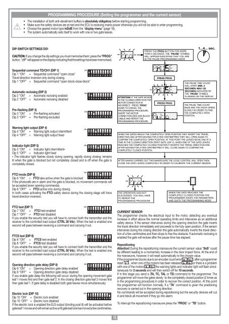
PROGRAMMING PROCEDURE (Setting the programmer and the current sensor)• The installation of both anti-derailment buffers is absolutely obligatory before starting programming.• Make sure the safety devices are at rest and the ECU is receiving mains power otherwise you will not be able to enter programming.• Choose the geared motor type inSidE from the "display menu" (page 16).• The system automatically sets itself to work with one or two gate leaves.DIP-SWITCH SETTINGS DS1CAUTION: If you change the dip settings you must memorise them; press the "PROG"button, "dIP" will appear on the display indicating that the settings have been memorised.PRESS THE PROG BUTTON FOR MORETHAN 4 SECONDS: THE "PAUSE" SYMBOLWILL APPEAR INDICATING THAT YOU AREIN THE PAUSE PROGRAMMING MODE1...4... sec.Sequential command TD/CH1 (DIP 1)ONDip 1 "ON" = Sequential command "open-close"Travel direction inversion only during closing.Dip 1 "OFF" = Sequential command "open-block-close-block"Automatic reclosing (DIP 2)Dip 2 "ON" = Automatic reclosing enabledDip 2 "OFF" = Automatic reclosing disabledPre-flashing (DIP 3)Dip 3 "ON" = Pre-flashing activatedDip 3 "OFF" = Pre-flashing excludedONON1 2 3 4 5 6 7 8 9 101 2 3 4 5 6 7 8 9 101 2 3 4 5 6 7 8 9 10ATTENTION! IF THE GATE MOVESIN THE CLOSING DIRECTION THEMOTOR CONNECTION ISINCORRECT. PRESS “PROG”AGAIN TO CANCEL THEPROGRAMMING PROCEDURE,INVERT THE MOTORCONNECTION (RED AND BLACKCABLE) AND REPEAT THEPROGRAMMING PROCEDURE.PRESS PROGPRESS PROGTHE PAUSE TIME COUNTWILL START (MIN. 2SECONDS: MAX 120SECONDS) INDICATED BYTHE "PAUSE" SYMBOLFLASHING ON THE DISPLAYTHE PAUSE TIME COUNTENDS AND THE DOOR OPENSSLOWLY IN ORDER TO FINDTHE COMPLETELY OPENPOSITION.Warning light output (DIP 4)Dip 4 "ON" = Warning light output intermittentDip 4 "OFF" = Warning light output fixedIndicator light (DIP 5)ONDip 5 "ON" = Indicator light intermittent*1 2 3 4 5 6 7 8 9 10Dip 5 "OFF" = Indicator light fixed* The indicator light flashes slowly during opening, rapidly during closing; remainslit when the gate is blocked but not completely closed and is off when the gate iscompletely closed.ON1 2 3 4 5 6 7 8 9 10WHEN THE GATES REACH THE COMPLETELY OPEN POSITION THEY INVERT THE TRAVELDIRECTION AND AFTER MOVING FOR A FEW CENTIMETRES THEY WILL OPEN AGAIN TOCONFIRM THE COMPLETELY OPEN POSITION. AT THIS POINT THE LEAVES MOVE ONE AT ATIME IN THE CLOSING DIRECTION (FIRST GATE LEAF 2). WHEN ONE OF THE GATE LEAVESREACHES THE COMPLETELY CLOSED POSITION IT INVERTS THE TRAVEL DIRECTION ANDAFTER MOVING FOR A FEW CENTIMETRES IT WILL CLOSE AGAIN TO CONFIRM THECOMPLETELY CLOSED POSITION.AFTER HAVING CARRIED OUT THIS MANOEUVRE THE LOGIC CONTROL WILL OPEN THENCLOSE THE GATE LEAVES COMPLETELY IN ORDER TO CALIBRATE THE CURRENT SENSOR.FTCI mode (DIP 6)Dip 6 "ON" = FTCI also active when the gate is blocked1 2 3 4 5 6 7 8 9 10If the photocells are in alarm and the gate is blocked, no movement commands willbe accepted (even opening commands).Dip 6 "OFF" = FTCI active only during closingIn both cases activating the FTCI safety device during the closing stage will forcetravel direction inversion.ONTHE OPERATION HAS NOTSUCCEEDED. YOU WILL HAVETO REPEAT THEPROGRAMMING PROCEDURE.WHEN THE GATE REACHES THECOMPLETELY CLOSED POSITION THEPROGRAMMER SAVES THE PARAMETERSAND QUITS THE PROGRAMMING MODEFTCI test (DIP 7)ONDip 7 "ON" = FTCI test enabled1 2 3 4 5 6 7 8 9 10Dip 7 "OFF" = FTCI test disabledIf you enable the security test you will have to connect both the transmitter and thereceiver to the controlled load output (CTRL 30 Vdc). When the test is enabled onesecond will pass between receiving a command and carrying it out.ONFTCS test (DIP 8)Dip 8 "ON" = FTCS test enabled1 2 3 4 5 6 7 8 9 10Dip 8 "OFF" = FTCS test disabledIf you enable the security test you will have to connect both the transmitter and thereceiver to the controlled load output (CTRL 30 Vdc). When the test is enabled onesecond will pass between receiving a command and carrying it out.ONOpening direction gate delay (DIP 9)Dip 9 "ON" = Opening direction gate delay enabled 1 2 3 4 5 6 7 8 9 10Dip 9 "OFF" = Opening direction gate delay disabledIf you enable gate delay the following will occur: during the opening movement gateleaf 1 moves first and then gate leaf 2. In the closing direction gate leaf 2 moves firstthen gate leaf 1. If gate delay is disabled both gate leaves move simultaneously.Electric lock (DIP 10)ONDip 10 "ON" = Electric lock enabled1 2 3 4 5 6 7 8 9 10Dip 10 "OFF" = Electric lock disabledIf the electric lock is enabled the ELS output (binding post 8) will be activated beforegate leaf 1 moves and will remain active until gate leaf one has moved a few centimetres.CURRENT SENSORThe programmer checks the electrical input to the motor, detecting any eventualincrease in effort above the normal operating limits and intervenes as an additionalsafety device. If the sensor intervenes during the opening direction the gate invertsthe travel direction immediately and proceeds to the fully open position. If the sensorintervenes during the closing direction the gate automatically inverts the travel directionof a few centimetres and then stops to free the obstacle. If automatic reclosing isenabled the gate will reclose after the pause time has elapsed.RepositioningAttention! During the repositioning manoeuvre the current sensor value “SnS" couldbe different leading to a momentary increase in the door impact force. At the end ofthe manoeuvre, however, it will reset automatically to the chosen value.If the programmer blocks due to an encoder count error , after a programmerreset , when one of the motors has been released or there is a problemwith one of the motors the warning lights and indicator light will flash simultaneouslyfor 2 seconds and will then switch off for 10 seconds.If in this stage you send a (TA, TC, TAL or TD) command to the programmer. Theprogrammer will move the gates slowly to the completely closed position (2 times asin the programming procedure) in order to recover the correct position. At this pointthe programmer will function normally. If a “TA" command is given the positioningrecovery is carried out in the opening direction.No commands will be accepted during repositioning but the security devices will cutin and block all movement if they go into alarm.To interrupt the repositioning manoeuvre press the “PROG" or “TB" button.15