Guideway system for medium duty applications - Güdel
Guideway system for medium duty applications - Güdel
Guideway system for medium duty applications - Güdel
- No tags were found...

You also want an ePaper? Increase the reach of your titles
YUMPU automatically turns print PDFs into web optimized ePapers that Google loves.
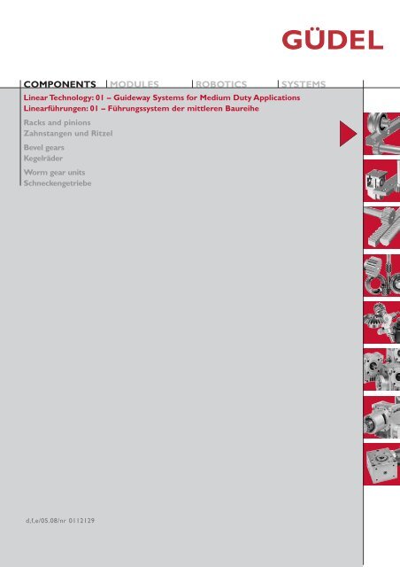
COMPONENTSMODULESROBOTICSLinear Technology: 01 – <strong>Guideway</strong> Systems <strong>for</strong> Medium Duty ApplicationsLinearführungen: 01 – Führungs<strong>system</strong> der mittleren BaureiheRacks and pinionsZahnstangen und RitzelBevel gearsKegelräderWorm gear unitsSchneckengetriebeSYSTEMSd,f,e/05.08/nr 0112129
Die Angaben in diesem Katalog wurden mitäusserster Sorgfalt erarbeitet und geprüft.Trotzdem kann für fehlerhafte oder unvollständigeAngaben keine Haftung übernommenwerden. Nachdruck, auch auszugsweise,ist nur mit unserer Genehmigunggestattet. Änderungen im Sinne technischerVerbesserungen bleiben vorbehalten.Ce catalogue a été soigneusement composéet toutes ses données vérifiées.Toutefois, nous déclinons toute responsabilitéen cas d’erreurs ou d’omissions. Parsuite du développement constant de nosrecherches, nous devons nous réservertout droit de modifications de produits denotre fabrication.This catalogue has been produced with agreat deal of care and attention. All datahas been checked <strong>for</strong> accuracy. However,no liability can be accepted <strong>for</strong> any incorrector incomplete data. All rights reserved.Reproduction in whole or in partwithout our authorisation is prohibited.
GÜDEL AGIndustrie NordCH-4900 LangenthalSwitzerlandphone +41 62 916 91 91fax +41 62 916 91 50eMail info@ch.gudel.comwww.gudel.comGÜDEL GmbHCarl-Benz-Strasse 5D-63674 AltenstadtGermanyphone +49 6047 9639 0fax +49 6047 9639 90eMail info@de.gudel.comwww.gudel.comGÜDEL Inc.4881 Runway Blvd.US-Ann Arbor, MI 48108USAphone +1 734 214 0000fax +1 734 214 9000eMail info@us.gudel.comwww.gudel.comALL LOCAL REPRESENTATIONS SEE:WWW.GUDEL.COM/GOLOCAL
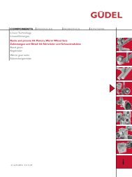
Einführung Introduction IntroductionDer vorliegende Katalog umfasst die Komponentender Linear- und Antriebstechnik. DerInhalt widerspiegelt die Erfahrung von mehr als5 Jahrzehnten der Entwicklung und Fertigungvon Längsführungen,Verzahnungen undGetriebebau.Das nach ISO 9001: 2000 aufgebaute Qualitäts<strong>system</strong>,eine grosse Lagerhaltung und ein weltweitesVertriebsnetz garantieren einen optimalenKundennutzen.Das umfangreiche Standardprogramm ermöglichteinen schnellen Zugriff auf alleKomponenten.Ein erfahrenes Ingenieurteam hilft Ihnen bei derAuswahl, erarbeitet mit Ihnen Einbauvorschlägeund optimiert Ihren Anwendungsfall.AuchSonderteile nach Ihren Zeichnungen stellen wirgerne für Sie her.Sprechen Sie mit uns!Le catalogue suivant comprend les composantsde la technique linéaire et d'entraînement. Lecontenu reflète l'expérience de plus de 5 décenniesde développement et de fabrication deguides longitudinaux, de dentures et de constructiond'engrenages.Le système de qualité élaboré selonISO 9001: 2000, un stock important et unréseau de distribution mondial garantissent auclient un profit optimal.La riche gamme standard permet un accès rapideà tous les composants.Une équipe d'ingénieurs expérimentés vousaidera à choisir, travaillera avec vous des projetsde montage et optimisera votre cas d'application.Nous fabriquerons également des piècesspéciales pour vous selon vos dessins.Parlez-nous de vos <strong>applications</strong>!This catalogue covers all the components ofthe linear and drive technology. Its contentreflects the experience of more than 5 decadesin the development and manufacture of linearguides, gears and gearboxes.A quality <strong>system</strong> based on ISO 9001: 2000, alarge inventory and a global distribution networkguarantee optimal benefits to the customer.The extensive standard programme makes rapidaccess to all components possible at all times.An experienced engineering team will help youin your selection, and assist you in drawing upinstallation proposals and in the optimisation ofyour application.We will also be pleased to manufacture customcomponents to your own drawings. Call us!Qualitätskontrolle Production et qualité Quality controlUm die hohen Qualitätsan<strong>for</strong>derungen unsererKundschaft zu erfüllen, werden die Module aufmodernsten Werkzeugmaschinen in eigenenWerken gefertigt. Die Qualitätskontrolle geschiehtgemäss ISO 9001 als Erststück- undStichprobenkontrolle.Dies garantiert unserer Kundschaft den Erwerbeines qualitativ hochwertigen Produktes.Pour satisfaire les exigences de notre clientèle,les modules sont fabriqués dans nos propresusines par des machines modernes.Le contrôle de qualité est fait suivant les exigencesde la norme ISO 9001.Tous ces ef<strong>for</strong>ts garantissent à notre clientèleun produit de haute qualité.To meet the high requirements of our clients,the modules are manufactured in our factoriesby modern machine tools. Quality control iscarried out in accordance with ISO 9001.This guarantees our clients a continuous highproduct quality.00.D
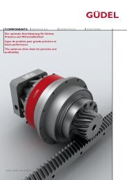
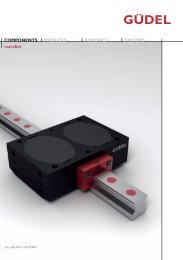
Linear<strong>system</strong> Système de guidage <strong>Guideway</strong> <strong>system</strong>Das Führungs<strong>system</strong> der mittleren Baureiheumfasst als Basiselemente Führungsrollen undPrismenschienen. Es eigenet sich besondersdort, wo hohe Geschwindigkeiten, geringeReibung, genaue Positionierung und grosseLaufruhe ge<strong>for</strong>dert werden.Unsere Ingenieure, denen entsprechendeRechnungsprogramme zur Verfügung stehen,helfen Ihnen gerne Ihren Anwendungsfall zuoptimieren.Le système de guidage pour charges moyennesest constitué des elements standard, galets deguidage et rails prismatiques. Le système estspécialement adapté pour les utilisations àhaute vitesse et positionnement précissoncoefficient de frottement est très faible ainsison bruit.De plus nos ingénieurs, à l’aide de programmesde calcule sont à votre disposition afin d’optimiservos <strong>applications</strong>.The guideway <strong>system</strong> <strong>for</strong> <strong>medium</strong> <strong>duty</strong> <strong>applications</strong>is based on standardized guideway rollersand vee bars.The <strong>system</strong> is especially suitable<strong>for</strong> <strong>applications</strong> requiring high velocities, lowfriction, exact positioning and quiet operation.Our engineers which are equipped with calculationprograms will be glad to help you to findthe right product <strong>for</strong> your application.01.00
INHALTSVERZEICHNISTABLE DES MATIÈRES / CONTENTPRODUKTÜBERSICHT Gamme de produits Product overview 01.02BAUKASTEN Le système modulaire The modular <strong>system</strong> 01.04GENAUIGKEIT Précision Accuracy 01.05VORSPANNUNG Précharge Preload 01.06KORROSIONSBESTÄNDIGKEIT Version résistant à la corrosion Corrosion resistant design 01.06SCHMIERUNG Lubrification Lubrication 01.07TRAGFÄHIGKEIT UND LEBENSDAUER Capacité de charge et durée de vie Load capacity and service life 01.08ANTRIEBSKRÄFTE UND MOMENTE Force de traction et couples Drive <strong>for</strong>ces and torques 01.09BAUGRÖSSENÜBERSICHT Gamme des tailles de fabrication Overview of Sizes 01.10BAUGRÖSSEN: 10 Taille de fabrication: 10 Size: 10 01.12BAUGRÖSSEN: 15 Taille de fabrication: 15 Size: 15 01.20BAUGRÖSSEN: 20 Taille de fabrication: 20 Size: 20 01.28BAUGRÖSSEN: 25 Taille de fabrication: 25 Size: 25 01.36BAUGRÖSSEN: 35 Taille de fabrication: 35 Size: 35 01.44ZUBEHÖR Accessoires Accessories 01.52TRAGFÄHIGKEITSBERECHNUNGEN Calculs de la capacité de charge Size verification 01.58WAHL DES SERVOGETRIEBE Sélection du réducteur Selection of worm gear drive unit 01.60BERECHNUNGSBEISPIEL Exemple de calcul Calculation example 01.62WARTUNG Entretien Maintenance 01.64EINBAU- UND AUSBAU Montage Assembly 01.66ANWENDUNGEN Applications Sample <strong>applications</strong> 01.7401.01
PRODUKTÜBERSICHTGAMME DES PRODUITSPRODUCT OVERVIEWElemente Eléments Elements01.1201.20 01.3601.28 01.4401.1301.21 01.3701.29 01.4501.1301.21 01.3701.29 01.4501.1401.22 01.3801.30 01.4601.1501.23 01.3901.31 01.4701.1501.23 01.3901.31 01.4701.1201.20 01.3601.28 01.4401.1201.20 01.3601.28 01.4401.1301.21 01.3701.29 01.4501.1601.24 01.4001.32 01.4801.1701.25 01.4101.33 01.4901.1901.27 01.4301.35 01.5101.02
Elemente Eléments Elements01.1801.26 01.4201.34 01.5001.1801.26 01.4201.34 01.5001.2601.3401.42 01.50Zubehör Accessoires Accessories01.5201.5301.5401.5501.5501.56 01.5701.03
BAUKASTENLE SYSTÈME MODULAIRETHE MODULAR SYSTEMDie Längsführungen und Antriebs<strong>system</strong>e sind in5 Baugrössen lieferbar. Innerhalb der Baugrössesind die Elemente beliebig kombinier- und austauschbar.Les guidages linéaires et les systèmes d'entraînementsont livrables en 5 tailles de fabrication.Les éléments de la même taille peuvent êtrecombinés ou échangés à gré.The linear guideways and drive <strong>system</strong>s can besupplied in 5 sizes.Within the same size the elementscan be combined and exchanged to meetrequirements.10 15 20 25 35Trägerprofil in Alu mit FührungenPoutre en alu avec railsTubular alu profile with guidewaysFührungsrolle mit AbstreiferschmiereinheitGalet du guidage avec racleur graisseurRoller <strong>for</strong> vee bars with wiper and lubrication unitSchneckengetriebeRéducteurWorm gear unitTrägerprofil in Stahl mit FührungenPoutre en acier avec railsTubular steel profile with guidewaysLaufwagenChariotCarriageFilzritzel-SchmierheinheitUnité de lubrification par pignon feutreFelt pinion lubrication unitSchneckengetriebeRéducteurWorm gear unit01.04
GENAUIGKEITPRÉCISIONACCURACYFührungenDie Genauigkeit des Führungs<strong>system</strong>s setzt sichaus der Grundgenauigkeit der Führungs-, RollenundAntriebselemente zusammen. Die Härte derFührungsbahnen beträgt 60-62HRC. Bei denrostfreien Schienen 56-58HRC.Guidage linéaireLa précision du système de guidage repose surla précision de base des éléments de guidage, deroulement et d'entraînement. Les surfaces deguidage sont trempées 60-62HRC. Les rails eninox 56-58HRC.Linear <strong>Guideway</strong>The accuracy of the guideway <strong>system</strong> is builtup from the basic accuracy of the guide, rollerand drive elements.The guiding surfaces are hardened60-62HRC. The guideways in stainlesssteel 56-58HRC.RollenDie Rollen sind als zweireihige Schrägkugellagermit einem Druckwinkel von 25° und beidseitigenRSR-Dichtscheiben und einer Lebensdauerfettfüllungin der Toleranzklasse PN hergestellt.Die Rollen sind lieferbar mit normaler und eingeengterLagerluft, mit zentrischem und exzentrischemBolzen und in einer rostfreienAusführung.GaletsLes galets sont réalisés en classe de tolérancePN. Ils se composent de roulements à billes àcontacte oblique ayant un angle de pression de25°, joints d’étanchéité RSR sur les deux côtés.Les galets sont livrables avec un jeu de paliernormal ou restreint, ainsi qu'avec un axe centriqueou excentrique et en version inoxydable.RollersThe rollers are manufactured in the PN toleranceclass as dual-row angular contact ball-bearingswith a pressure angle of 25° with RSRsealing washers on both sides, and a lifetimegrease packing.The rollers can be supplied withnormal or pre-loaded bearing clearances, withconcentric or eccentric centres. They are alsomanufactured in stainless steel.BaugrösseTaille / Size Ga (µm) ➀ Ga (µm) ➁10 +6/+23 –3/+515 +6/+23 –3/+520 +6/+23 –3/+525 +8/+27 –3/+535 +11/+33 –3/+5➀ Normale axiale Lagerluft ➀ Jeu de palier normale ➀ Normal bearing clearance➁ Eingeengte axiale Lagerluft ➁ Jeu de palier restreint ➁ Preloaded bearing clearanceAntriebselementeDie Verzahnungen sind für den normalenAnwendungsfall feinstverzahnt. Für höhereBeanspruchungen und grössere Genauigkeit sindsie gehärtet und geschliffen.Eléments d’entraînementLes dentures ont un taillage de précision pour lecas d’utilisation normal. Pour répondre à dessollicitations plus élevée, elles sont trempées etrectifiées.Drive elementsRacks are supplied in various sizes to meet therequired application. For high accuracy and hightorque <strong>applications</strong>, the racks are hardened andground.Quality fp (mm) Fp (mm) p (mm)weich, softQuality7h25hart, trempéQuality6h23feinstverzahnt0.008 0.05 0/– 0.02 taillée à précisionprecision cutgehärtet und geschliffen0.006 0.03 0/– 0.01 trempée et rectifiée 56 – 58HRChardened and groundfp (mm):Teilungs-EinzelabweichungErreur individuelle de pasAdjacent pitch errorFp (1000 mm):Teilungs-GesamtabweichungErreur totale de pasCumulative pitch errorp (mm):AblängtoleranzTolérance de coupe par rapport au pasPitch tolerance of cut01.05
VORSPANNUNGPRÉCHARGEPRELOADKORROSIONSBESTÄNKIGKEITVERSION RÉSISTANT À LA CORROSIONCORROSION RESISTANT DESIGNDie Spieleinstellung und Vorspannung der Rollenerfolgt über die Exzenter der Führungs- undLaufrollen der TypenreiheFR.., FR..A, FR..R bzw.LR.., LR..A, LR..R.Die Typenreihe FR..Z, FR..ZA und LR..Z sindin zentrischer Ausführung. Bei denExzenterrollen sind die Innenbolzen mit zweiBohrungen versehen die in genauer Positionzum Exzenter sind.Le réglage du jeu et de la précontrainte desgalets se fait par l'intermédiaire des excentriquesdes galets de guidage et de roulement de lasérieFR.., FR..A, FR..R, resp.LR.., LR..A, LR..R.Les séries FR..Z, FR..ZA et LR..Z sont en versioncentrique. Sur les galets excentriques, lesaxes interiéurs sont pourvus de deux alésagesexactement positionnés par rapport a l'excentrique.The backlash setting and the pre-tensioning ofthe rollers takes place via the eccentric hub ofthe rollers of the seriesFR.., FR..A, FR..R orLR.., LR..A, LR..R.The FR..Z, FR..ZA and LR..Z series are theconcentric models. In the eccentric rollers, theinner bolts are provided with two holes. Theseallow <strong>for</strong> the adjustment of the backlash.Position 0Position +1Position –1Befinden sich die Rolle in der Nullage ergebensich für das Zahnspiel die Standardwerte 0.05mm Flankenspiel.Durch zu grosse Vorspannung wird dieLebensdauer des Systems herabgesetzt. Durchzu kleine Vorspannung kommen die Rollen nichtzum Tragen oder nutzen sich durch schlechtenEingriff vorzeitig ab. Angaben zum Einbau werdenauf Seite 01.66 gemacht.Für Präzisionsmaschinen und Anwendungen miterhöhten An<strong>for</strong>derungen an Steifigkeit stehenRollen der Typreihe FR..A, FR..ZA und LR..Amit eingeengtem Axialspiel zur Verfügung. DieSteifigkeit eines System wird weitgehend beeinflusstdurch Wahl der Rollen und Vorspannungdes Systems.ReibungDie Rollenführungen haben einen sehr niedrigenReibungskoeffizient. Durch Abstreifer auf denSchienen wird dieser Wert leicht erhöht.µ = 0.01 – 0.03Korrosionsbeständigkeit:Die Elemente der Typenreihe mit derNachbezeichnung ..R werden in rostfreierAusführung geliefert.FR..R FührungsrolleLR..R LaufrolleFS.. R FührungsschieneFZ..R FührungszahnstangeLS.. R LaufschieneLZ..R LaufzahnstangeRostfreie Trägerprofile können auf Anfragegeliefert werden.01.06Si le rouleau se trouve en position zéro, il enrésulte pour les dents, des valeurs standard de0.05 mm de jeu sur les flancs.Une contrainte trop importante réduit la duréede vie du système. Une contrainte insuffisante apour conséquence que les galets ne reposentpas, ou qu'ils s'usent prématurément à la suited'un mauvais contact. Des in<strong>for</strong>mations relativesau montage se trouvent à la page 01.66.Pour les machines de précision et des <strong>applications</strong>avec une demande de rigidité elevée, il existedes galets de la serie FR..A, FR..ZA etLR..A à jeu axial réduit. La rigidité d'un systèmedépend largement du choix des galets et de laprécontrainte du <strong>system</strong>e.FrottementLes guidages à galets ont un très faible coefficientde frottement. Des racleurs montés sur lesrails augmentent légèrement cette valeur.Résistance à la corrosionLes éléments de la gamme portant la designationadditionnelle ..R sont fabriqués en versioninoxydable.FR..R Galets de guidageLR..R Galets de roulementFS..R Rails de guidageFZ..R Rails crémaillères de guidageLS..R Rails de roulementLZ..R Rails crémaillères de roulementDes profiles inoxydables peuvent être livrées surdemande.If a roller is located in its zero position, the teethbacklash will be the standard value of 0.05 mmflank clearance.The service life of the <strong>system</strong> will be reduced byexcessive tensioning.With too little tension therollers will not run, or will wear due to the poormeshing. In<strong>for</strong>mation regarding installation isgiven on Page 01.66.For precision machinery and <strong>applications</strong> withincreased stiffness requirements there are rollersavailable of the FR..A, FR..ZA and LR..Aseries with pre-loaded bearings. The stiffness ofthe <strong>system</strong> is thereby largely determined by theselection of the rollers and the pre-tensioning ofthe <strong>system</strong>.FrictionThe roller guides have a very low coefficient offriction.This value is slightly increased by the fittingof wipers to the rails.Corrosion resistanceElements of the series with the suffix ..R areavailable in stainless steel.FR..R <strong>Guideway</strong> rollersLR..R Plain rollersFS..R <strong>Guideway</strong> vee railsFZ..R <strong>Guideway</strong> vee racksLS..R <strong>Guideway</strong> flat railsLZ..R <strong>Guideway</strong> racksStainless beams can be supplied on request.
SCHMIERUNGLUBRIFICATIONLUBRICATIONEine ausreichende Schmierung ist ebenso wichtigwie die korrekte Wahl der Baugrösse und derMontage des Führungs<strong>system</strong>s.Eine ausreichende und im Vorfeld der Konstruktiongeplante Schmierung reduziert Reibung undAbnützung und vemindert Passungsrost.Tribokorrosionist immer ein Anzeichen für nicht ausreichendeSchmierung. Bei den Führungs<strong>system</strong>en istbezüglich Schmierung folgendes zu unterscheiden:RollenRollen sind mit ESSO Beacon EP2 erstbefettet.DieSchmierung ist ausgelegt für die Erreichung desvollen Verfahrweges von 100 000 km.SchienenZur Schmierung der Laufbahnen der FührungsundLaufschienen sollten die Abstreif- undSchmierungseinheiten verwendet werden (Fig. ➀).Ein geölter Filzeinsatz schmiert die Laufbahnen.Nach Bedarf wird der seitlich angebrachteSchmiernippel zur Nachschmierung benutzt .Nachschmierung ist er<strong>for</strong>derlich im Rahmen dernormalen Anlagewartung und der Einsatzbedingungen,spätestens wenn sich erste Spuren vonTribokorrosion zeigen (rötliche Verfärbung derLaufbahnen).Mit dem nachfüllbaren autonomen Schmierstoffspenderund Kolbenverteiler steht ein automatischesNachschmier<strong>system</strong> von mehreren AbstreifundSchmiereinheiten zur Verfügung (Fig. ➁).Eine Nachschmierung wird alle 100km oder 150hempfohlen.Kennzeichnung Schmiernippel: roter RingUne lubrification suffisante est tout aussi importanteque le choix correcte de la taille du <strong>system</strong>e de guidageet le montage.Une lubrification suffisante lors de l'étude réduit lefrottement et l'usure,empêchant ainsi la <strong>for</strong>mation dela rouille de contact.La tribocorrosion est toujours un signe de lubrificationinsuffisante. En ce qui concerne la lubrification surles système de guidage, il faut distinguer ce qui suit:GaletsLa lubrification initiale des galets se fait avec ESSOBeacon EP2. La lubrification est calculée pour unedurée de 100 000 km.RailsPour graisser les glissières et les rails de guidage et deroulement, il faut utiliser les unités de racleur et delubrification (fig. ➀).Un insert en feutre, imbibé d'huile, lubrifie les glissières.Suivant les besoins, on utilise pour la relubrificationle graisseurs monté sur une côté.Une bonne lubrification permet d’augmenter la duréede vie d’un système. Par contre il est impératif degraisser au huile lors de l’apparition des premièrestraces de tribocorrossion (décoloration rougeâtredes glissières).Un distributeur de lubrifiant autonome et rechargeablepermet une relubrification automatique deplusieurs unités de racleur et de lubrification (fig. ➁).Un regraissage est recommandé tous les 100km ou150h.Identification du graisseur: bague rougeSufficient lubrication is as important as the correctselection of the size of the guideway <strong>system</strong>and the assembly.Lubrication that is correctly chosen and suppliedat the beginning of the design reduces frictionand prevents tribocorrosion. Tribocorrosion isalways an indication of insuffcient lubrication. Inthe guideway <strong>system</strong>, the following must be differentiatedwith regards to lubrication:RollersThe rollers are initially greased with ESSOBeacon EP2.The lubrication is designed to last<strong>for</strong> the full displacement path of 100 000 km.RailsFor the lubrication of the running surfaces, thewiper and lubrication units should be used (Fig.➀).An oiled felt insert lubricates the running surfaces.When necessary, the lube nipple fitted toone side is used <strong>for</strong> re-filling the oil resevoir.Re-filling is necessary during normal maintenanceand application conditions, no later thenwhen the first signs of tribocorrosion appear(red coloration of the running track).An automatic re-lubrication of several wiper andlube units is available utilizing a central lubrication<strong>system</strong> (Fig. ➁).Regreasing is recommended every 100km or150h.Identification of grease nipple: red ringFig. ➀Fig. ➁VerzahnungRitzel und Zahnstange sind regelmässig zu Wartenund mit einem Haftfett nachzuschmieren.Auf Anfrage ist eine Schmiereinheit mit geöltemFilzritzel erhältlich. Das Filzritzel lässt sichmanuell oder über ein automatisches Schmier<strong>system</strong>mit Öl nachschmieren.Eine Nachschmierung wird alle 100km oder 150hempfohlen.Kennzeichnung Schmiernippel: roter RingDentureLe pignon et la crémaillère doivent faire l'objetd'un entretien régulier, et seront regraissés avecde la graisse haute pression.Sur demande une unité de lubrification par pignonfeutre imbibé d’huile peut être fourni.La relubrification du pignon peut se faire manuellementou par un système automatique.Un regraissage est recommandé tous les 100kmou 150h.Identification du graisseur: bague rougeGear teethThe pinion and the rack must be maintainedregularly, and be relubricated with an adhesivegrease.On request a unit with an oil soaked felt pinionis available.The felt pinion can either be manually or automaticallylubricated.Regreasing is recommended every 100km or150h.Identification of grease nipple: red ring01.07
TRAGFÄHIGKEIT UND LEBENSDAUERCAPACITÉ DE CHARGE ET DURÉE DE VIELOAD CAPACITY AND SERVICE LIFEAuswahl der Baugrösse Sélection dimensionelle Size selectionF aF r10 15 20 25 35Die Angaben erlauben eine Grobselektion der Baugrössen des Führungs<strong>system</strong>s.Die C w-Werte sind in dieser Tabelle für eine nominelle Lebensdauervon 10 8 m (100 000 km) angegeben und beziehen sich auf eine Rollebei rein radialer oder axialer Belastung. Bei den Masstabellen der Rollensind die Werte für C 0w und C w (10 6 m) zusätzlich angegeben.Im Falle von kombinierten Axial- und Radiallasten und Stössen sind dieBerechnungsangaben auf Seite 01.58 zu berücksichtigen oder ein Berechnungsnachweisbeim Lieferanten anzu<strong>for</strong>dern.C w (10F 8 m)rkN6543210C w (10 8 m)F kNa2.0Les indications permettent de procéder à une sélection dimensionelle dusystème de guidage. Les valeurs C w sont mentionnées dans ce tableaupour une durée de vie nominale de 10 8 (100 000 km), et se rapportent àun galet sollicité de manière purement radiale ou axiale. En outre, lesvaleurs pour C 0w et C w (10 6 m) sont indiquées dans les tableaux dimensionnelsdes galets.En cas des charges combinées et de chocs, il faudra tenir compte des calculsprésentés sur la page 01.58, ou bien demander une confirmation deceux à nos ingénieurs.1.51.00.5This data allows <strong>for</strong> a rough selection of the size of the required guideway<strong>system</strong>. The C w values are listed in this table <strong>for</strong> a nominal service life of10 8 m (100 000km), and refer to a roller with pure radial or axial loading.In the dimensional tables <strong>for</strong> the rollers, the values <strong>for</strong> C 0w and C w(10 6 m) are also given.In cases of combined loading and shock, the calculation data on Page 01.58must be consulted, or a calculation verification can be requested from themanufacturer.10 15 20 25 35Baugrösse / Taille / Size001.08
ANTRIEBSKRÄFTE UND MOMENTEFORCES DE TRACTION ET COUPLESDRIVE FORCES AND TORQUESÜberprüfung der Antriebskräfte Contrôler les <strong>for</strong>ces de traction Control of drive <strong>for</strong>cesT NF NT N1412108F NkNF N-6Nach erfolgter Wahl der Baugrösse muss die Verzahnung der Führungs<strong>system</strong>eauf die ge<strong>for</strong>derten Antriebskräfte und Momente überprüft werden.Die Verzahnungen sind in weicher sowie gehärteter und geschliffener Ausführunglieferbar.Die angegebenen Werte haben Gültigkeit bei guter Schmierung, stossfreiemBetrieb und stabiler Lagerung.Ein Sicherheitsfaktor für Zahnfussbeanspruchung S F ≥ 1.4 und einSicherheitsfaktor für Zahnflankenbeanspruchung S H ≥ 1.0 ist einberechnet.Ein Sicherheitsfaktor S B ≈ 1.0 ... 4.0 ist nach Erfahrung zu berücksichtigen.Die Längskraft F N ist in Abhängigkeit von der Zähnezahl z des Ritzels angegeben.Après avoir sélectionné la taille, il faut également contrôler la denture dessystèmes de guidage, en ce qui concerne les <strong>for</strong>ces de traction et les couplesappliqués.Les dentures peuvent être livrées aussi bien en version non-trempée qu’enversion trempée et rectifiée.Les valeurs indiquées sont des valeurs obtenues en fonctionnement sanschocs, avec lubrification et montage rigide du pignon.Un coefficient de sécurité pour la contrainte de flexion S F ≥ 1.4 et un coefficientde sécurité pour la pression superficielle S H ≥ 1.0 sont respectés.Un coefficient de sécurité S B ≈ 1.0 ... 4.0 doit être intégré en fonction del’application.La <strong>for</strong>ce de traction F N est indiquée en fonction du nombre de dents z dupignon.After selecting the rack, the gear teeth of the guideway <strong>system</strong> must bechecked <strong>for</strong> compatibility with the required drive <strong>for</strong>ces and torques.The rack can be supplied precision cut or hardened and ground.The values given are values <strong>for</strong> shock-free operation, good lubrication andstiff arrangement of the pinion.A safety factor <strong>for</strong> tooth root stress S F ≥ 1.4 and a safety factor <strong>for</strong>Hertzian stress S H ≥ 1.0 is taken in account.Depending on your experiences and the application a safety factorS B ≈ 1.0 ... 4.0 has to be considered.The traction <strong>for</strong>ce F N is related to the number of teeth z of the pinion.-10 15 20 25 35feinstverzahnttaillée à précisionprecision cutgehärtet und geschliffentrempée et rectifiéehardened and ground420T NNm450400350300250200150100Baugrösse GetriebeTaille RéducteurSize Gearbox Seite / Page10 AE 030 01.1915 AE 045 01.2720 AE 045 01.3525 AE 060 01.4335 AE 090 01.5110 15 20 25 35feinstverzahnttaillée à précisionprecision cutgehärtet und geschliffentrempée et rectifiéehardened and ground50001.09
BAUGRÖSSEN 1:1TAILLESSIZES101520253501.10
101520253501.11
BAUGRÖSSE 10TAILLE 10SIZE 10KonstruktionsabmasseCotes de montageMounting dimensionsFührungsrolle Galet de guidage Roller <strong>for</strong> vee barsDIN 912 8.8M6x30M A9,9 NmType Part No. Excenter Ga (µm) Mat. m (kg)FR 10 900 710 1 mm +6/+23 100Cr6 1.3505 0,15FR 10 A 900 711 1 mm –3/+5 100Cr6 1.3505 0,15FR 10 Z 900 712 0 mm +6/+23 100Cr6 1.3505 0,15FR 10 ZA 900 714 0 mm –3/+5 100Cr6 1.3505 0,15FR 10 R 900 713 1 mm +6/+23 X46Cr13 1.4034 0,15Ga Axiale Lagerluft, jeu axial, internal axial clearanceTragfähigkeit / Capacité de charge / Load carrying capacityC0W (N) CW➀ (N) CW➁ (N) nmax (min -1 )5 300 4 900 1 060 12 0004 800 4 400 950 12 0005 300 4 900 1 060 12 0004 800 4 400 950 12 0003 900 3 700 800 12 000Weg, Chemin parcouru, Distance: ➀ 10 6 m ➁ 10 8 mBefestigungsflansch Bride de fixation Mounting flangebrüniert noirçi black oxideDIN 912 8.8M4x12M A2,9 NmType Part No. Mat. m (kg)SP 10 902 011 Ck45 1.1191 0,1SPE 10 902 040 Ck45 1.1191 0.07Seite / Page 01.52Abstreifer-Schmiereinheit Racleur graisseur Wiper and lubrication unit➀➀DIN 912 8.8M4x18M A2,9 Nm➀ Ölgetränkter FilzFeutre imbibé d’huileOil soaked felt insertsType Part No. Mat. m (kg)RA 10 900 040 PA-6/POM 0,02501.12
KonstruktionsabmasseCotes de montageMounting dimensionsFührungsschiene Rail de guidage <strong>Guideway</strong> vee bar10Type Part No. L L0 L1 Mat. m (kg)FS 100 900 310 1 030 1 032.55 1 000 58CrMoV4 1.7792 1,40900 311 630 632.55 600 58CrMoV4 1.7792 0,85900 312 330 332.55 300 58CrMoV4 1.7792 0,45DIN 912 8.8M5x12M A5,75 NmFS 100 R 900 990 630 632.55 600 X46Cr13 1.4034 0,85Führungszahnstange Rail crémaillère de guidage <strong>Guideway</strong> vee rackType Part No. L L1 Module p Mat. m (kg)FZ 10 G 900 055 870,22 850 1,0 3,142 58CrMoV4 1.7792 1,15p (mm) Teilung, pas, pitchhart, trempéQuality6h23EinbauMontage / AssemblySeite / Page 01.71Antriebsritzel Pignon Drive pinionType Part No. z Module p Mat. m (kg)WR 10.1 201025 25 1,0 3,142 16MnCr5 1.7131 0,09p (mm) Teilung, pas, pitchhart, trempéQuality6f2401.13
BAUGRÖSSE 10TAILLE 10SIZE 10KonstruktionsabmasseCotes de montageMounting dimensionsLaufrolle Galet de roulement Plain rollerDIN 912 8.8M6x30M A9,9 NmType Part No. Excenter Ga (µm) Mat. m (kg)LR 10 900 810 1 mm +6/+23 100Cr6 1.3505 0,18LR 10 A 900 811 1 mm –3/+5 100Cr6 1.3505 0,18LR 10 Z 900 812 0 mm +6/+23 100Cr6 1.3505 0,18LR 10 R 900 813 1 mm +6/+23 X46Cr13 1.4034 0,18Ga Axiale Lagerluft, jeu axial, internal axial clearanceTragfähigkeit / Capacité de charge / Load carrying capacityC0W (N) CW➀ (N) CW➁ (N) nmax (min ) -15 300 4 900 1 060 12 0004 800 4 400 950 12 0005 300 4 900 1 060 12 0003 900 3 700 800 12 000Weg, Chemin parcouru, Distance: ➀ 10 6 m ➁ 10 8 mBefestigungsflansch Bride de fixation Mounting Flangebrüniert noirçi black oxideDIN 912 8.8M4x12M A2,9 NmType Part No. Mat. m (kg)SP 10 902 011 Ck45 1.1191 0,1SPE 10 902 040 Ck45 1.1191 0.07Seite / Page 01.52Abstreifer-Schmiereinheit Racleur graisseur Wiper and lubrication unit➀➀DIN 912 8.8M4x18M A2,9 Nm➀ Ölgetränkter FilzFeutre imbibé d’huileOil soaked felt insertsType Part No. Mat. m (kg)RAL 10 900 045 PA-6/POM 0,02501.14
KonstruktionsabmasseCotes de montageMounting dimensionsLaufschiene Rail de roulement <strong>Guideway</strong> flat rail10Type Part No. L L0 L1 Mat. m (kg)LS 100 900 610 1 030 1 032.55 1 000 58CrMoV4 1.7792 1,50900 611 630 632.55 600 58CrMoV4 1.7792 0,90900 612 330 332.55 300 58CrMoV4 1.7792 0,50DIN 912 8.8M5x12M A5,75 NmLS 100 R 901 000 630 632.55 600 X46Cr13 1.4034 0,90Laufzahnstange Rail crémaillère de roulement <strong>Guideway</strong> rackType Part No. L L1 Module p Mat. m (kg)LZ 10 G 900 056 870,22 850 1,0 3,142 58CrMoV4 1.7792 1,20p (mm) Teilung, pas, pitchhart, trempéQuality6h23EinbauMontage / AssemblySeite / Page 01.71Antriebsritzel Pignon Drive pinionType Part No. z Module p Mat. m (kg)WR 10.1 201025 25 1,0 3,142 16MnCr5 1.7131 0,09p (mm) Teilung, pas, pitchhart, trempéQuality6f2401.15
BAUGRÖSSE 10TAILLE 10SIZE 10KonstruktionsabmasseCotes de montageMounting dimensionsTrägerprofil in Stahl mit Führungen Poutre en acier avec rails Tubular steel profile with guidewaysDie Profile sind sandgestrahlt, grundiertund bearbeitet zur Aufnahme der Schienen.Die Führungen werden gemäss Bestellbeispielspezifiert. Die Portale werden mit montiertenSchienen geliefert. Auf Anfrage werden sie mit2-Komponentenfarbe lackiert.Poutre sablé avec peinture d’après. Usinée pourréception des rails. Livrée avec ses rails montésselon exemple de commande.Sur demande peinture en 2 composants.The profiles are sandblasted, primed and machinedto carry the rails. The profiles are suppliedwith mounted guideways. On request the profilesare painted with 2 coats of semi-gloss paint.Type Mat. m ➀ (kg/m) m ➁ (kg/m) I x➀ (cm 4 ) I x➁ (cm 4 ) I y➀ (cm 4 ) I y➁ (cm 4 ) I z (cm 4 )LP 80/40-10 St52-3 1.0570 10.4 13.3 29 42 95 124 73➀ ohne Schienen / sans rails / without guideway bars➁ mit Schienen / avec rails / with guideway barsLP 80/80-10 St52-3 1.0570 14.4 17.2 164 209 164 189 256Bestellbeispiel Exemple de commande Ordering exampleType LP 80/40-10 FZ 10 / FS 100 1670 mm – RAL 6002Spezifikation der Schienen gemäss Seiten 01.13, 01.15 / Sélection des rails selonpage 01.13, 01.15 / Selection of guideways according to page 01.13, 01.15Länge, longueur, length L tot + 10 mmOption: Stirnseitiges Bohrbild nur auf Bestellung / Sur demande trous de fixation aux extremités / On request fixing holes on front sidesOption: Farblackierung / Peinture en 2 composants / Semi-gloss paintDie gesamte Schienenlänge L tot sollte wennmöglich aus der Summe der Teillängen derElemente gebildet werden.La longueur totale L tot des rails devait être lasomme des longueurs individuelles des rails.Overall length L tot of the guideways should bethe sum of each length of the elements.L tot = n 1 •1030 + n 2 • 630 + n 3 • 33001.16
ALP 60/60KonstruktionsabmasseCotes de montageMounting dimensionsALP 80/50ALP 80/80Trägerprofil in Alu mit Führungen Poutre en alu avec rails Tubular alu profiles with guidewaysGezogen und bearbeitet zur Aufnahme derFührungsschienen. Die Profile werden mit montiertenSchienen geliefert. Auf Wunsch könnensie eloxiert werden.Profils filés et usiné pour réception des rails.Livré avec ses rails montés. Sur demandeanodisé.Extruded and machined. The profiles are suppliedwith mounted guideways. On request, theprofiles can be anodized.10Type Mat. m ➀ (kg/m) m ➁ (kg/m) I x➀ (cm 4 ) I x➁ (cm 4 ) I y➀ (cm 4 ) I y➁ (cm 4 ) I z (cm 4 )ALP 60/60-10 AlMgSi 0.5 4.7 7.6 74 101 76 87 54➀ ohne Schienen / sans rails / without guideway bars➁ mit Schienen / avec rails / with guideway barsOption: Stirnseitiges Bohrbild nur auf Bestellung / Sur demande trous de fixation aux extremités / On request fixing holes on front sidesALP 80/50-10 AlMgSi 0.5 5.5 8.4 56 76 130 156 56ALP 80/80-10 AlMgSi 0.5 6.8 9.7 179 226 181 205 79Option: Stirnseitiges Bohrbild nur auf Bestellung / Sur demande trous de fixation aux extremités / On request fixing holes on front sides01.17
BAUGRÖSSE 10TAILLE 10SIZE 10Laufwagen Chariot Carriage1-Axish yTrägerprofil / Poutre / ProfileType Part No. ( incl. SP Flansche excl. FR Rollen) Mat. m (kg) h y PzWP 10.0 902 010 AlMg4.5 Mn 2,2 LP 80/40/10 —LP 80/80/10 —ALP 80/50/10 —ALP 80/80/10 —1-Axish yFür Anbau desHochleistungsgetriebesAE030Pour montage duréducteur AE030For fitting of worm gearunit AE030Trägerprofil / Poutre / ProfileType Part No. ( incl. SP Flansche excl. FR Rollen) Mat. m (kg) h y PzWP 10.1 902 061 AlMg4.5 Mn 2,1 LP 80/40/10 —LP 80/80/10 —ALP 80/50/10 —ALP 80/80/10 —01.18
Hochleistungs-Schneckengetriebe Réducteur à haute per<strong>for</strong>mance Worm gear unitType AE030L ausgelegt für Flansch mit t 1 = 12mmL sur la base d’une épaisseur de flange t 1 = 12mmL based on a flange thickness t 1 = 12mm20 < L < 3310Pos. ➄Pos. ➃ Pos. ➀ Pos. ➁DIN 912 8.8Fig. ➁Pos. ➂Fig. ➀Pos. ➀ Getriebe / Réducteur / Worm gear unitPart No. Ratio InertiaL i J (10 -7 kg m 2 ) m (kg)403 000 2 : 1 138 1,63 : 1 694 : 1 455 : 1 346 : 1 288 : 1 2210 : 1 1913 1 /3 :1 1716 : 1 1624 : 1 15i: ab Lager / du stock / from stockPos. ➃ Flansch / Bride / FlangePart No. Fig S r F t1 t2 D M m (kg)403 083 ➀ 40 63 55 12 4 — M4 0.2403 090 ➀ 50 70 60 12 4 — M5403 081 ➀ 50 95 82 12 4 — M6403 082 ➀ 60 75 70 12 4 — M5403 091 ➀ 60 90 75 12 4 — M5403 086 ➀ 70 85 80 12 4 — M6403 092 ➀ 70 90 80 12 4 — M6403 080 ➀ 80 100 92 12 4 — M6403 087 ➀ 80 100 90 21 8 — M6 0.3403 085 ➁ 60 75 — 12 4 90 5,8Pos. ➁ Abtrieb mit Ritzel / Bride de sortie avec pignon /Output flange with pinionPart No. Modul p z m (kg)403 052 1,0 3,142 25 0,4p (mm):Teilung / pas / pitchPos. ➂ Distanzstück / Entretoise / SpacerPart No.m (kg)403 060 0.2Pos. ➄ Kupplung / Accouplement / CouplingInertiaPart No. d J (10 -6 kg m 2 ) T1max (Nm) MA (Nm) m (kg)403 023 8 11.5 3.4 M3x16 1.37 0.1403 022 9 11.5 3.8 M3x16403 025 10 11.0 4.0 M3x16403 021 11 11.0 4.7 M3x16403 020 14 11.0 6.0 M3x16T1max: maximal übertragbares Moment der Kupplung / Couple max. del’accouplement / Maximum torque of couplingMA: Anziehdrehmoment / Couple de serrage / Tightening torque01.19
BAUGRÖSSE 15TAILLE 15SIZE 15KonstruktionsabmasseCotes de montageMounting dimensionsFührungsrolle Galet de guidage Roller <strong>for</strong> vee barsDIN 912 8.8M8x35M A24 NmType Part No. Excenter Ga (µm) Mat. m (kg)FR 15 900 715 1 mm +6/+23 100Cr6 1.3505 0,25FR 15 A 900 716 1 mm –3/+5 100Cr6 1.3505 0,25FR 15 Z 900 717 0 mm +6/+23 100Cr6 1.3505 0,25FR 15 ZA 900 719 0 mm –3/+5 100Cr6 1.3505 0,25FR 15 R 900 718 1 mm +6/+23 X46Cr13 1.4034 0,25Ga Axiale Lagerluft, jeu axial, internal axial clearanceTragfähigkeit / Capacité de charge / Load carrying capacityC0W (N) CW➀ (N) CW➁ (N) nmax (min -1 )6 800 7 200 1 560 9 0006 100 6 500 1 400 9 0006 800 7 200 1 560 9 0006 100 6 500 1 400 9 0005 100 5 400 1 170 9 000Weg, Chemin parcouru, Distance: ➀ 10 6 m ➁ 10 8 mBefestigungsflansch Bride de fixation Mounting flangebrüniert noirçi black oxideDIN 912 8.8M5x16M A5,75 NmType Part No. Mat. m (kg)SP 15 902 016 Ck45 1.1191 0,15SPE 15 902 041 Ck45 1.1191 0,11Seite / Page 01.52Abstreifer-Schmiereinheit Racleur graisseur Wiper and lubrication unit➀➀DIN 912 8.8M4x18M A2,9 Nm➀ Ölgetränkter FilzFeutre imbibé d’huileOil soaked felt insertsType Part No. Mat. m (kg)RA 15 900 041 PA-6/POM 0,0301.20
KonstruktionsabmasseCotes de montageMounting dimensionsFührungsschiene Rail de guidage <strong>Guideway</strong> vee bar15Type Part No. L L0 L1 Mat. m (kg)FS 150 900 315 1 030 1 033.89 1 000 58CrMoV4 1.7792 2,60900 316 630 633.89 600 58CrMoV4 1.7792 1,60900 317 330 333.89 300 58CrMoV4 1.7792 0,85DIN 912 8.8M6x16M A9,9 NmFS 150 R 900 991 630 633.89 600 X42Cr13 1.2083 1,60Führungszahnstange Rail crémaillère de guidage <strong>Guideway</strong> vee rackFig. ➀Fig. ➁Type Part No. L L1 Module p Fig. Mat. m (kg)FZ 15 900 115 1 030 1 000 1.5915 5,0 ➀ 58CrMoV4 1.7792 2,40900 116 630 600 1.5915 5,0 ➀ 58CrMoV4 1.7792 1,50900 117 330 300 1.5915 5,0 ➀ 58CrMoV4 1.7792 0,80FZ 15 G 900 060 1 030 1 000 1.5915 5,0 ➁ 58CrMoV4 1.7792 2,40900 061 630 600 1.5915 5,0 ➁ 58CrMoV4 1.7792 1,50900 062 330 300 1.5915 5,0 ➁ 58CrMoV4 1.7792 0,80FZ 15 R 900 996 630 600 1.5915 5,0 ➁ X46Cr13 1.2083 1,50p (mm) Teilung, pas, pitchweich, softQuality7h25hart, trempéQuality6h23EinbauMontage / AssemblySeite / Page 01.71Antriebsritzel Pignon Drive pinionFig. ➀Fig. ➁Type Part No. z Module p Fig. Mat. m (kg)WR 15 900 915 20 1,5915 5,0 ➀ 16MnCr5 1.7131 0,25MR 5 154 050 20 1,5915 5,0 ➁ 16MnCr5 1.7131 0,10p (mm) Teilung, pas, pitchhart, trempéQuality6f2401.21
BAUGRÖSSE 15TAILLE 15SIZE 15KonstruktionsabmasseCotes de montageMounting dimensionsLaufrolle Galet de roulement Plain rollerDIN 912 8.8M8x35M A24 NmType Part No. Excenter Ga (µm) Mat. m (kg)LR 15 900 815 1 mm +6/+23 100Cr6 1.3505 0,18LR 15 A 900 816 1 mm –3/+5 100Cr6 1.3505 0,18LR 15 Z 900 817 0 mm +6/+23 100Cr6 1.3505 0,18LR 15 R 900 818 1 mm +6/+23 X46Cr13 1.4034 0,18Ga Axiale Lagerluft, jeu axial, internal axial clearanceTragfähigkeit / Capacité de charge / Load carrying capacityC0W (N) CW ➀ (N) CW ➁ (N) nmax (min -1 )6 800 7 200 1 560 9 0006 100 6 500 1 400 9 0006 800 7 200 1 560 9 0005 100 5 400 1 170 9 000Weg, Chemin parcouru, Distance: ➀ 10 6 m ➁ 10 8 mBefestigungsflansch Bride de fixation Mounting Flangebrüniert noirçi black oxideDIN 912 8.8M5x16M A5,75 NmType Part No. Mat. m (kg)SP 15 902 016 Ck45 1.1191 0,15SPE 15 902 041 Ck45 1.1191 0,11Seite / Page 01.52Abstreifer-Schmiereinheit Racleur graisseur Wiper and lubrication unit➀➀DIN 912 8.8M4x18M A2,9 Nm➀ Ölgetränkter FilzFeutre imbibé d’huileOil soaked felt insertsType Part No. Mat. m (kg)RAL 15 900 046 PA-6/POM 0,0301.22
KonstruktionsabmasseCotes de montageMounting dimensionsLaufschiene Rail de roulement Flat rail15Type Part No. L L0 L1 Mat. m (kg)LS 150 900 615 1 030 1 033.89 1 000 58CrMoV4 1.7792 2,80900 616 630 633.89 600 58CrMoV4 1.7792 1,70900 617 330 333.89 300 58CrMoV4 1.7792 0,90DIN 912 8.8M6x16M A9,9 NmLS 150 R 901 001 630 633.89 600 X42Cr13 1.2083 1,70Laufzahnstange Rail crémaillère de roulement <strong>Guideway</strong> rackFig. ➀Fig. ➁Type Part No. L L1 Module p Fig. Mat. m (kg)LZ 15 900 415 1 030 1 000 1.5915 5,0 ➀ 58CrMoV4 1.7792 2,60900 416 630 600 1.5915 5,0 ➀ 58CrMoV4 1.7792 1,60900 417 330 300 1.5915 5,0 ➀ 58CrMoV4 1.7792 0,85LZ 15 G 900 063 1 030 1 000 1.5915 5,0 ➁ 58CrMoV4 1.7792 2,60900 064 330 300 1.5915 5,0 ➁ 58CrMoV4 1.7792 0,85LZ 15 R 901 006 630 600 1.5915 5,0 ➁ X42Cr13 1.2083 1,60p (mm) Teilung, pas, pitchweich, softQuality7h25hart, trempéQuality6h23EinbauMontage / AssemblySeite / Page 01.71Antriebsritzel Pignon Drive pinionFig. ➀Fig. ➁Type Part No. z Module p Fig. Mat. m (kg)WR 15 900 915 20 1,5915 5,0 ➀ 16MnCr5 1.7131 0,25MR 5 154 050 20 1,5915 5,0 ➁ 16MnCr5 1.7131 0,10p (mm) Teilung, pas, pitchhart, trempéQuality6f2401.23
BAUGRÖSSE 15TAILLE 15SIZE 15KonstruktionsabmasseCotes de montageMounting dimensionsTrägerprofil in Stahl mit Führungen Poutre en acier avec rails Tubular steel profile with guidewaysDie Profile sind sandgestrahlt, grundiertund bearbeitet zur Aufnahme der Schienen.Die Führungen werden gemäss Bestellbeispielspezifiert. Die Portale werden mit montiertenSchienen geliefert. Auf Anfrage werden sie mit2-Komponentenfarbe lackiert.Poutre sablé avec peinture d’après. Usinée pourréception des rails. Livrée avec ses rails montésselon exemple de commande.Sur demande peinture en 2 composants.The profiles are sandblasted, primed and machinedto carry the rails. The profiles are suppliedwith mounted guideways. On request the profilesare painted with 2 coats of semi-gloss paint.Type Mat. m ➀ (kg/m) m ➁ (kg/m) I x➀ (cm 4 ) I x➁ (cm 4 ) I y➀ (cm 4 ) I y➁ (cm 4 ) I z (cm 4 )LP 100/50-15 St52-3 1.0570 14.8 20.4 69 111 218 306 169➀ ohne Schienen / sans rails / without guideway bars➁ mit Schienen / avec rails / with guideway barsLP 140/140-15 St52-3 1.0570 39.6 45.2 1 400 1 660 1 400 1 550 2 250Bestellbeispiel Exemple de commande Ordering exampleType LP 140/140-15 FZ 15 / FS 150 2400 mm – RAL 3006Spezifikation der Schienen gemäss Seiten 01.21, 01.23 / Sélection des rails selonpage 01.21, 01.23 / Selection of guideways according to page 01.21, 01.23Länge, longueur, length L tot + 10 mmOption: Stirnseitiges Bohrbild nur auf Bestellung / Sur demande trous de fixation aux extremités / On request fixing holes on front sidesOption: Farblackierung / Peinture en 2 composants / Semi-gloss paintDie gesamte Schienenlänge L tot sollte wennmöglich aus der Summe der Teillängen derElemente gebildet werden.La longueur totale L tot des rails devait être lasomme des longueurs individuelles des rails.Overall length L tot of the guideways should bethe sum of each length of the elements.L tot = n 1 •1030 + n 2 • 630 + n 3 • 33001.24
Trägerprofil in Alu mit Führungen Poutre en alu avec rails Tubular alu profiles with guidewaysGezogen und bearbeitet zur Aufnahme derFührungsschienen. Die Profile werden mit montiertenSchienen geliefert. Auf Wunsch könnensie eloxiert werden.ALP 80/80 ALP 110/110KonstruktionsabmasseCotes de montageMounting dimensionsProfils filés et usiné pour réception des rails.Livré avec ses rails montés. Sur demandeanodisé.Extruded and machined. The profiles are suppliedwith mounted guideways. On request, theprofiles can be anodized.15ALP 80/80-15 AIMgSi 0.5 6.8 12.4 179 279 181 227 79➂ Stirnseitiges Bohrbild nur auf Bestellung / Sur demande trous de fixation aux extremités / On request fixing holes on front sidesALP 110/110-15 AIMgSi 0.5 12.3 17.9 606 788 609 705 341Option: Stirnseitiges Bohrbild nur auf Bestellung / Sur demande trous de fixation aux extremités / On request fixing holes on front sides01.25
BAUGRÖSSE 15TAILLE 15SIZE 15Laufwagen Chariot Carriage1-Axish yTrägerprofil / Poutre / ProfileType Part No. ( incl. SP Flansche excl. FR Rollen) Mat. m (kg) h y PzWP 15.0 902 015 AlMg4.5 Mn 4,1 LP 100/50-15 —ALP 100/60-15 —1-Axish yFür Anbau desHochleistungsgetriebesAE045Pour montage duréducteur AE045For fitting of worm gearunit AE045Type Part No. ( incl. SP Flansche excl. FR Rollen) Mat. m (kg) h y PzWP 15.1 902 065 AlMg4.5 Mn 3,9 LP 100/50-15 —ALP 100/60-15 —2-Axish y f zFür Anbau desHochleistungsgetriebesAE045Pour montage duréducteur AE045For fitting of worm gearunit AE045Type Part No. ( incl. SP Flansche excl. FR Rollen) Mat. m (kg) h y PzWP 15.2 902 066 AlMg4.5 Mn 7.9 LP 140/140-15 ALP 80/80-1501.26
Hochleistungs-Schneckengetriebe Réducteur à haute per<strong>for</strong>mance Worm gear unitType AE045 L ausgelegt für Flansch mit t 1 = 14mmL sur la base d’une épaisseur de flange t 1 = 14mmL based on a flange thickness t 1 = 14mm33 ≤ L2 < 4320 < L1 < 3315Pos. ➄Pos. ➃ Pos. ➀ Pos. ➁DIN 912 8.8Fig. ➁Pos. ➂Fig. ➀Pos. ➀ Getriebe / Réducteur / Worm gear unitPart No. Ratio InertiaL 1 L 2 i J (10 -6 kg m 2 ) m (kg)404 500 404 510 2 : 1 97 3,53 : 1 474 : 1 295 : 1 216 : 1 168 : 1 1210 : 1 1013 1 /3 :1 816 : 1 724 : 1 6i: ab Lager / du stock / from stockPos. ➃ Flansch / Bride / FlangePart No. Fig. S r F t1 t2 D M m (kg)404 590 ➀ 50 70 70 14 4 — M5 0.25404 581 ➀ 50 95 82 14 4 — M6404 582 ➀ 60 75 70 14 4 — M5404 592 ➀ 60 90 75 14 4 — M5404 585 ➀ 70 85 80 14 4 — M6404 593 ➀ 70 90 80 14 4 — M6404 580 ➀ 80 100 92 14 4 — M6404 594 ➀ 80 100 90 18 8 — M6404 583 ➀ 95 115 100 14 4 — M8404 595 ➀ 110 145 120 14 4 — M8 0.3404 587 ➀ 95 115 105 23 11 — M8404 584 ➁ 70 85 — 14 4 105 ø7404 586 ➁ 80 100 — 14 4 120 ø7Pos. ➁ Abtrieb mit Ritzel / Bride de sortie avec pignon /Output flange with pinionPart No. Module p z m (kg)404 550 1.5915 5.0 20 1.7p (mm):Teilung / pas / pitchPos. ➂ Distanzstücke / Entretoise / SpacerPart No.m (kg)404 560 ➀ 0.25➀ Lieferung paarweise / Livraison en paire / Delivery in pairsPos. ➄ Kupplung / Accouplement / CouplingInertiaPart No. d J (10 -6 kg m 2 ) T1max (Nm) MA (Nm) m (kg)404 523 9 28 6.7 M4x16 3.1 0.15404 522 11 27 8.2 M4x16404 521 14 26 10.4 M4x16404 525 16 26 12.0 M4x16404 520 19 25 14.2 M4x16T1max: maximal übertragbares Moment der Kupplung / Couple max. del’accouplement / Maximum torque of couplingMA: Anziehdrehmoment / Couple de serrage / Tightening torque01.27
BAUGRÖSSE 20TAILLE 20SIZE 20KonstruktionsabmasseCotes de montageMounting dimensionsFührungsrolle Galet de guidage Roller <strong>for</strong> vee barsDIN 912 8.8M10x50M A48 NmType Part No. Excenter Ga (µm) Mat. m (kg)FR 20 900 720 1 mm +6/+23 100Cr6 1.3505 0,50FR 20 A 900 721 1 mm –3/+5 100Cr6 1.3505 0,50FR 20 Z 900 722 0 mm +6/+23 100Cr6 1.3505 0,50FR 20 ZA 900 724 0 mm –3/+5 100Cr6 1.3505 0,50FR 20 R 900 723 1 mm +6/+23 X46Cr13 1.4034 0,50Ga Axiale Lagerluft, jeu axial, internal axial clearanceTragfähigkeit / Capacité de charge / Load carrying capacityC0W (N) CW ➀ (N) CW ➁ (N) nmax (min -1 )9 500 10 200 2 200 7 0008 600 9 000 2 000 7 0009 500 10 200 2 200 7 0008 600 9 000 2 000 7 0007 100 7 500 1 650 7 000Weg, Chemin parcouru, Distance: ➀ 10 6 m ➁ 10 8 mBefestigungsflansch Bride de fixation Mounting flangebrüniert noirçi black oxideDIN 912 8.8M6x16M A9,9 NmType Part No. Mat. m (kg)SP 20 902 021 Ck45 1.1191 0,25SPE 20 902 042 Ck45 1.1191 0,18Seite / Page 01.52Abstreifer-Schmiereinheit Racleur graisseur Wiper and lubrication unit➀➀DIN 912 8.8M5x20M A5 Nm➀ Ölgetränkter FilzFeutre imbibé d’huileOil soaked felt insertsType Part No. Mat. m (kg)RA 20 900 042 PA-6/POM 0,0401.28
KonstruktionsabmasseCotes de montageMounting dimensionsFührungsschiene Rail de guidage <strong>Guideway</strong> vee bar20Type Part No. L L0 L1 Mat. m (kg)FS 200 900 320 1 030 1 035.23 1 000 58CrMoV4 1.7792 4,00900 321 630 635.23 600 58CrMoV4 1.7792 2,50900 322 330 335.23 300 58CrMoV4 1.7792 1,30DIN 912 8.8M8x20M A24 NmFS 200 R 900 992 630 635.23 600 X42Cr13 1.2083 2,40Führungszahnstange Rail crémaillère de guidage <strong>Guideway</strong> vee rackFig. ➀Fig. ➁Type Part No. L L1 Module p Fig. Mat. m (kg)FZ 20 900 120 1 030 1 000 1.5915 5,0 ➀ 58CrMoV4 1.7792 3,90900 121 630 600 1.5915 5,0 ➀ 58CrMoV4 1.7792 2,40900 122 330 300 1.5915 5,0 ➀ 58CrMoV4 1.7792 1,25FZ 20 G 900 070 1 030 1 000 1.5915 5,0 ➁ 58CrMoV4 1.7792 3,90900 071 630 600 1.5915 5,0 ➁ 58CrMoV4 1.7792 2,40900 072 330 300 1.5915 5,0 ➁ 58CrMoV4 1.7792 1,25FZ 20 R 900 997 630 600 1.5915 5,0 ➁ X42Cr13 1.2083 2,40p (mm) Teilung, pas, pitchweich, softQuality7h25hart, trempéQuality6h23EinbauMontage / AssemblySeite / Page 01.71Antriebsritzel Pignon Drive pinionFig. ➀Fig. ➁Type Part No. z Module p Fig. Mat. m (kg)WR 20 900 920 20 1.5915 5,0 ➀ 16MnCr5 1.7131 0,30MR 5 154 050 20 1.5915 5,0 ➁ 16MnCr5 1.7131 0,10p (mm) Teilung, pas, pitchhart, trempéQuality6f2401.29
BAUGRÖSSE 20TAILLE 20SIZE 20KonstruktionsabmasseCotes de montageMounting dimensionsLaufrolle Galet de roulement Plain rollerDIN 912 8.8M10x50M A48 NmType Part No. Excenter Ga (µm) Mat. m (kg)LR 20 900 820 1 mm +6/+23 100Cr6 1.3505 0,70LR 20 A 900 821 1 mm –3/+5 100Cr6 1.3505 0,70LR 20 Z 900 822 0 mm +6/+23 100Cr6 1.3505 0,70LR 20 R 900 823 1 mm +6/+23 X46Cr13 1.4034 0,70Ga Axiale Lagerluft, jeu axial, internal axial clearanceTragfähigkeit / Capacité de charge / Load carrying capacityC0W (N) CW ➀ (N) CW ➁ (N) nmax (min -1 )9 500 10 200 2 200 7 0008 600 9 000 2 000 7 0009 500 10 200 2 200 7 0007 100 7 500 1 650 7 000Weg, Chemin parcouru, Distance: ➀ 10 6 m ➁ 10 8 mBefestigungsflansch Bride de fixation Mounting flangebrüniert noirçi black oxideDIN 912 8.8M6x16M A9,9 NmType Part No. Mat. m (kg)SP 20 902 021 Ck45 1.1191 0,25SPE 20 902 042 Ck45 1.1191 0,18Seite / Page 01.52Abstreifer-Schmiereinheit Racleur graisseur Wiper and lubrication unitDIN 912 8.8M5x20M A5 Nm➀ Ölgetränkter FilzFeutre imbibé d’huileOil soaked felt insertsType Part No. Mat. m (kg)RAL 20 900 047 PA-6/POM 0,0401.30
KonstruktionsabmasseCotes de montageMounting dimensionsLaufschiene Rail de roulement <strong>Guideway</strong> flat rail20Type Part No. L L0 L1 Mat. m (kg)LS 200 900 620 1 030 1 035.23 1 000 58CrMoV4 1.7792 4,40900 621 630 635.23 600 58CrMoV4 1.7792 2,70900 622 330 335.23 300 58CrMoV4 1.7792 1,50DIN 912 8.8M8x20M A24 NmLS 200 R 901 002 630 635.23 600 X42Cr13 1.2083 2,70Laufzahnstange Rail crémaillère de roulement <strong>Guideway</strong> rackFig. ➀Fig. ➁Type Part No. L L1 Module p Fig. Mat. m (kg)LZ 20 900 420 1 030 1 000 1.5915 5,0 ➀ 58CrMoV4 1.7792 4,20900 421 630 600 1.5915 5,0 ➀ 58CrMoV4 1.7792 2,60900 422 330 300 1.5915 5,0 ➀ 58CrMoV4 1.7792 1,35LZ 20 G 900 073 1 030 1 000 1.5915 5,0 ➁ 58CrMoV4 1.7792 4,20900 074 330 300 1.5915 5,0 ➁ 58CrMoV4 1.7792 1,35LZ 20 R 901 007 630 600 1.5915 5,0 ➁ X42Cr13 1.2083 2,60p (mm) Teilung, pas, pitchweich, softQuality7h25hart, trempéQuality6h23EinbauMontage / AssemblySeite / Page 01.71Antriebsritzel Pignon Drive pinionFig. ➀Fig. ➁Type Part No. z Module p Fig. Mat. m (kg)WR 20 900 920 20 1.5915 5,0 ➀ 16MnCr5 1.7131 0,30MR 5 154 050 20 1.5915 5,0 ➁ 16MnCr5 1.7131 0,10p (mm) Teilung, pas, pitchhart, trempéQuality6f2401.31
BAUGRÖSSE 20TAILLE 20SIZE 20KonstruktionsabmasseCotes de montageMounting dimensionsTrägerprofil in Stahl mit Führungen Poutre en acier avec rails Tubular steel profile with guidewaysDie Profile sind sandgestrahlt, grundiertund bearbeitet zur Aufnahme der Schienen.Die Führungen werden gemäss Bestellbeispielspezifiert. Die Portale werden mit montiertenSchienen geliefert.Auf Anfrage werden sie mit 2-Komponentenfarbe lackiert.Poutre sablé avec peinture d’après. Usinée pourréception des rails. Livrée avec ses rails montésselon exemple de commande.Sur demande peinture en 2 composants.The profiles are sandblasted, primed and machinedto carry the rails. The profiles are suppliedwith mounted guideways. On request the profilesare painted with 2 coats of semi-gloss paint.Type Mat. m ➀ (kg/m) m ➁ (kg/m) I x➀ (cm 4 ) I x➁ (cm 4 ) I y➀ (cm 4 ) I y➁ (cm 4 ) I z (cm 4 )LP 160/90-20 St52-3 1.0570 34.1 43.1 524 737 1 310 1 710 1 280➀ ohne Schienen / sans rails / without guideway bars➁ mit Schienen / avec rails / with guideway barsLP 160/160-20 St52-3 1.0570 45.1 54.1 2 100 2 690 2 100 2 460 3 470Bestellbeispiel Exemple de commande Ordering exampleType LP 160/160-20 FZ 20 / FS 200 5160 mm – RAL 2004Spezifikation der Schienen gemäss Seiten 01.29, 01.31 / Sélection des rails selonpage 01.29, 01.31 / Selection of guideways according to page 01.29, 01.31Länge, longueur, length L tot + 10 mmOption: Stirnseitiges Bohrbild nur auf Bestellung / Sur demande trous de fixation aux extrémités / On request fixing holes on front sidesOption: Farblackierung / Peinture en 2 composants / Semi-gloss paintDie gesamte Schienenlänge L tot sollte wennmöglich aus der Summe der Teillängen derElemente gebildet werden.La longueur totale L tot des rails devrait être lasomme des longueurs individuelles des rails.Overall length L tot of the guideways should bethe sum of each length of the elements.L tot = n 1 •1030 + n 2 • 630 + n 3 • 33001.32
ALP 150/80 ALP 110/110 ALP 150/150KonstruktionsabmasseCotes de montageMounting dimensionsTrägerprofil in Alu mit Führungen Poutre en alu avec rails Tubular alu profiles with guidewaysGezogen und bearbeitet zur Aufnahme derFührungsschienen. Die Profile werden mit montiertenSchienen geliefert. Auf Wunsch könnensie eloxiert werden.Profils filés et usiné pour réception des rails.Livré avec ses rails montés. Sur demandeanodisé.Extruded and machined. The profiles are suppliedwith mounted guideways. On request, theprofiles can be anodized.20Type Mat. m ➀ (kg/m) m ➁ (kg/m) I x➀ (cm 4 ) I x➁ (cm 4 ) I y➀ (cm 4 ) I y➁ (cm 4 ) I z (cm 4 )ALP 150/80-20 AIMgSi 0.5 17.7 26.7 469 660 1 550 1 880 626➀ ohne Schienen / sans rails / without guideway bars➁ mit Schienen / avec rails / with guideway barsALP 110/110-20 AlMgSi 0.5 12.3 21.3 606 922 609 763 341Option: Stirnseitiges Bohrbild nur auf Bestellung / Sur demande trous de fixation aux extremités / On request fixing holes on front sidesALP 150/150-20 AIMgSi 0.5 23.0 32.0 2 080 2 640 2 270 2 560 1 250Option: Stirnseitiges Bohrbild nur auf Bestellung / Sur demande trous de fixation aux extremités / On request fixing holes on front sides01.33
BAUGRÖSSE 20TAILLE 20SIZE 20Laufwagen Chariot Carriage1-Axish yTrägerprofil / Poutre / ProfileType Part No. ( incl. SP Flansche excl. FR Rollen) Mat. m (kg) h y PzWP 20.0 902 020 AlMg4.5 Mn 8,3 LP 160/ 90-20 —LP 160/160-20 —ALP 150/ 80-20 —ALP 150/150-20 —1-Axish yFür Anbau desHochleistungsgetriebesAE045Pour montage duréducteur AE045For fitting of worm gearunit AE045Type Part No. ( incl. SP Flansche excl. FR Rollen) Mat. m (kg) h y PzWP 20.1 902 070 AlMg4.5 Mn 8,0 LP 160/ 90-20 —LP 160/160-20 —ALP 150/ 80-20 —ALP 150/150-20 —2-Axish y f zFür Anbau desHochleistungsgetriebesAE045Pour montage duréducteur AE045For fitting of worm gearunit AE045Type Part No. ( incl. SP Flansche excl. FR Rollen) Mat. m (kg) h y PzWP 20.2 902 071 AlMg4.5 Mn 12,0 LP 160/ 90-20 ALP 110/110-20LP 160/160-20 ALP 110/110-2001.34
Hochleistungs-Schneckengetriebe Réducteur à haute per<strong>for</strong>mance Worm gear unitType AE045 L ausgelegt für Flansch mit t 1 = 14mmL sur la base d’une épaisseur de flange t 1 = 14mmL based on a flange thickness t 1 = 14mm33 ≤ L2 < 4320 < L1 < 3320Pos. ➄ Pos. ➃ Pos. ➀ Pos. ➁DIN 912 8.8Fig. ➁Pos. ➂Fig. ➀Pos. ➀ Getriebe / Réducteur / Worm gear unitPart No. Ratio InertiaL1 L2 i J (10 -6 kg m 2 ) m (kg)404 500 404 510 2 : 1 97 3,53 : 1 474 : 1 295 : 1 216 : 1 168 : 1 1210 : 1 1013 1 /3 :1 816 : 1 724 : 1 6i: ab Lager / du stock / from stockPos. ➃ Flansch / Bride / FlangePart No. Fig. S r F t1 t2 D M m (kg)404 590 ➀ 50 70 70 14 4 — M5 0.25404 581 ➀ 50 95 82 14 4 — M6404 582 ➀ 60 75 70 14 4 — M5404 592 ➀ 60 90 75 14 4 — M5404 585 ➀ 70 85 80 14 4 — M6404 593 ➀ 70 90 80 14 4 — M6404 580 ➀ 80 100 92 14 4 — M6404 594 ➀ 80 100 90 18 8 — M6404 583 ➀ 95 115 100 14 4 — M8404 595 ➀ 110 145 120 14 4 — M8 0.3404 587 ➀ 95 115 105 23 11 — M8404 584 ➁ 70 85 — 14 4 105 ø7404 586 ➁ 80 100 — 14 4 120 ø7Pos. ➁ Abtrieb mit Ritzel / Bride de sortie avec pignon /Output flange with pinionPart No. Module p z m (kg)404 551 1.5915 5.0 20 1.7p (mm):Teilung / pas / pitchPos. ➂ Distanzstücke / Entretoise / SpacerPart No.m (kg)404 560 ➀ 0.25➀ Lieferung paarweise / Livraison en paire / Delivery in pairsPos. ➄ Kupplung / Accouplement / CouplingInertiaPart No. d J (10 -6 kg m 2 ) T1max (Nm) MA (Nm) m (kg)404 523 9 28 6.7 M4x16 3.1 0.15404 522 11 27 8.2 M4x16404 521 14 26 10.4 M4x16404 525 16 26 12.0 M4x16404 520 19 25 14.2 M4x16T1max: maximal übertragbares Moment der Kupplung / Couple max. del’accouplement / Maximum torque of couplingMA: Anziehdrehmoment / Couple de serrage / Tightening torque01.35
BAUGRÖSSE 25TAILLE 25SIZE 25KonstruktionsabmasseCotes de montageMounting dimensionsFührungsrolle Galet de guidage Roller <strong>for</strong> vee barsDIN 912 8.8M12x60MA83 NmType Part No. Excenter Ga (µm) Mat. m (kg)FR 25 900 725 1 mm +8/+27 100Cr6 1.3505 1,1FR 25 A 900 726 1 mm –3/+5 100Cr6 1.3505 1,1FR 25 Z 900 727 0 mm +8/+27 100Cr6 1.3505 1,1FR 25 ZA 900 729 0 mm –3/+5 100Cr6 1.3505 1,1FR 25 R 900 728 1 mm +8/+27 X46Cr13 1.4034 1,1Ga Axiale Lagerluft, jeu axial, internal axial clearanceTragfähigkeit / Capacité de charge / Load carrying capacityC0W (N) CW ➀ (N) CW ➁ (N) nmax (min -1 )15 000 16 300 3 530 5 60013 500 14 700 3 200 5 60015 000 16 300 3 530 5 60013 500 14 700 3 200 5 60011 000 12 450 2 650 5 600Weg, Chemin parcouru, Distance: ➀ 10 6 m ➁ 10 8 mBefestigungsflansch Bride de fixation Mounting flangebrüniert noirçi black oxideDIN 912 8.8M8x20M A24 NmType Part No. Mat. m (kg)SP 25 902 026 Ck45 1.1191 0,5SPE 25 902 043 Ck45 1.1191 0,32Seite / Page 01.52Abstreifer-Schmiereinheit Racleur graisseur Wiper and lubrication unit➀➀DIN 912 8.8M6x25M A8.6 Nm➀ Ölgetränkter FilzFeutre imbibé d’huileOil soaked felt insertsType Part No. Mat. m (kg)RA 25 900 043 PA-6/POM 0,0601.36
KonstruktionsabmasseCotes de montageMounting dimensionsFührungsschiene Rail de guidage <strong>Guideway</strong> vee bar25Type Part No. L L0 L1 Mat. m (kg)FS 250 900 325 1 230 1 236.62 1 200 58CrMoV4 1.7792 7,0900 326 930 936.62 900 58CrMoV4 1.7792 5,3900 327 630 636.62 600 58CrMoV4 1.7792 3,6900 328 330 336.62 300 58CrMoV4 1.7792 1,9FS 250 R 900 993 630 636.62 600 X42Cr13 1.2083 3,6DIN 912 8.8M8x25M A24 NmFührungszahnstange Rail crémaillère de guidage <strong>Guideway</strong> vee rackFig. ➀Fig. ➁Type Part No. L L1 Module p Fig. Mat. m (kg)FZ 25 900 125 1230 1200 2.3873 7,50 ➀ 58CrMoV4 1.7792 6,4900 126 930 900 2.3873 7,50 ➀ 58CrMoV4 1.7792 4,85900 127 630 600 2.3873 7,50 ➀ 58CrMoV4 1.7792 3,25900 128 330 300 2.3873 7,50 ➀ 58CrMoV4 1.7792 1,7FZ 25 G 900 075 1230 1200 2.3873 7,50 ➁ 58CrMoV4 1.7792 6,4900 076 630 600 2.3873 7,50 ➁ 58CrMoV4 1.7792 3,25900 077 330 300 2.3873 7,50 ➁ 58CrMoV4 1.7792 1,7FZ 25 R 900 998 630 600 2.3873 7,50 ➁ X42Cr13 1.2083 3,25p (mm) Teilung, pas, pitchweich, softQuality7h25hart, trempéQuality6h23EinbauMontage / AssemblySeite / Page 01.71Antriebsritzel Pignon Drive pinionFig. ➀Fig. ➁Type Part No. z Module p Fig. Mat. m (kg)WR 25 900 925 20 2.3873 7,50 ➀ 16MnCr5 1.7131 0,6MR 7,5 154 075 20 2.3873 7,50 ➁ 16MnCr5 1.7131 0,35p (mm) Teilung, pas, pitchhart, trempéQuality6f2401.37
BAUGRÖSSE 25TAILLE 25SIZE 25KonstruktionsabmasseCotes de montageMounting dimensionsLaufrolle Galet de roulement Plain rollerDIN 912 8.8M12x60M A83 NmType Part No. Excenter Ga (µm) Mat. m (kg)LR 25 900 825 1 mm +8/+27 100Cr6 1.3505 1,1LR 25 A 900 826 1 mm –3/+5 100Cr6 1.3505 1,1LR 25 Z 900 827 0 mm +8/+27 100Cr6 1.3505 1,1LR 25 R 900 828 1 mm +8/+27 X46Cr13 1.4034 1,1Ga Axiale Lagerluft, jeu axial, internal axial clearanceTragfähigkeit / Capacité de charge / Load carrying capacityC0W (N) CW ➀ (N) CW ➁ (N) nmax (min -1 )15 000 16 300 3 530 5 60013 500 14 700 3 200 5 60015 000 16 300 3 530 5 60011 000 12 450 2 650 5 600Weg, Chemin parcouru, Distance: ➀ 10 6 m ➁ 10 8 mBefestigungsflansch Bride de fixation Mounting flangebrüniert noirçi black oxideDIN 912 8.8M8x20M A24 NmType Part No. Mat. m (kg)SP 25 902 026 Ck45 1.1191 0,5SPE 25 902 043 Ck45 1.1191 0,32Seite / Page 01.52Abstreifer-Schmiereinheit Racleur graisseur Wiper and lubrication unit➀➀DIN 912 8.8M6x25M A8.6 Nm➀ Ölgetränkter FilzFeutre imbibé d’huileOil soaked felt insertsType Part No. Mat. m (kg)RAL 25 900 048 PA-6/POM 0,0601.38
KonstruktionsabmasseCotes de montageMounting dimensionsLaufschiene Rail de roulement <strong>Guideway</strong> flat rail25Type Part No. L L0 L1 Mat. m (kg)LS 250 900 625 1 230 1 236.62 1 200 58CrMoV4 1.7792 7,60900 626 930 936.62 900 58CrMoV4 1.7792 5,75900 627 630 636.62 600 58CrMoV4 1.7792 3,80900 628 330 336.62 300 58CrMoV4 1.7792 1,95LS 250 R 901 003 630 636.62 600 X42Cr13 1.2083 3,80DIN 912 8.8M8x25M A24 NmLaufzahnstange Rail crémaillère de roulement <strong>Guideway</strong> rackFig. ➀Fig. ➁Type Part No. L L1 Module p Fig. Mat. m (kg)LZ 25 900 425 1230 1200 2.3873 7,50 ➀ 58CrMoV4 1.7792 7,00900 426 930 900 2.3873 7,50 ➀ 58CrMoV4 1.7792 5,25900 427 630 600 2.3873 7,50 ➀ 58CrMoV4 1.7792 3,60900 428 330 300 2.3873 7,50 ➀ 58CrMoV4 1.7792 1,90LZ 25 G 900 078 1230 1200 2.3873 7,50 ➁ 58CrMoV4 1.7792 7,00900 079 330 300 2.3873 7,50 ➁ 58CrMoV4 1.7792 1,90LZ 25 R 901 008 630 600 2.3873 7,50 ➁ X42Cr13 1.2083 3,60p (mm) Teilung, pas, pitchweich, softQuality7h25hart, trempéQuality6h23EinbauMontage / AssemblySeite / Page 01.71Antriebsritzel Pignon Drive pinionFig. ➀Fig. ➁Type Part No. z Module p Fig. Mat. m (kg)WR 25 900 925 20 2.3873 7,50 ➀ 16MnCr5 1.7131 0,6MR 7,5 154 075 20 2.3873 7,50 ➁ 16MnCr5 1.7131 0,35p (mm) Teilung, pas, pitchhart, trempéQuality6f2401.39
BAUGRÖSSE 25TAILLE 25SIZE 25KonstruktionsabmasseCotes de montageMounting dimensionsTrägerprofil in Stahl mit Führungen Poutre en acier avec rails Tubular steel profile with guidewaysDie Profile sind sandgestrahlt, grundiertund bearbeitet zur Aufnahme der Schienen.Die Führungen werden gemäss Bestellbeispielspezifiert. Die Portale werden mit montiertenSchienen geliefert. Auf Anfrage werden sie mit2-Komponentenfarbe lackiert.Poutre sablé avec peinture d’après. Usinée pourréception des rails. Livrée avec ses rails montésselon exemple de commence.Sur demande peinture en 2 composants.The profiles are sandblasted, primed and machinedto carry the rails. The profiles are suppliedwith mounted guideways. On request the profilesare painted with 2 coats of semi-gloss paint.Type Mat. m ➀ (kg/m) m ➁ (kg/m) I x➀ (cm 4 ) I x➁ (cm 4 ) I y➀ (cm 4 ) I y➁ (cm 4 ) I z (cm 4 )LP 220/120-25 St52-3 1.0570 48.2 61.1 1 410 1 940 3 680 4 860 3 420➀ ohne Schienen / sans rails / without guideway bars➁ mit Schienen / avec rails / with guideway barsLP 220/220-25 St52-3 1.0570 63.9 76.7 5 890 7 450 5 890 6 960 9 470Bestellbeispiel Exemple de commande Ordering exampleType ALP 150/150-25 FZ 25 G / FS 250 3400 mm – –Spezifikation der Schienen gemäss Seiten 01.37, 01.39 / Sélection des rails selonpage 01.37, 01.39 / Selection of guideways according to page 01.37, 01.39Länge, longueur, length L tot + 10 mmOption: Stirnseitiges Bohrbild nur auf Bestellung / Sur demande trous de fixation aux extremités / On request fixing holes on front sidesOption: Farblackierung / Peinture en 2 composants / Semi-gloss paintDie gesamte Schienenlänge L tot sollte wennmöglich aus der Summe der Teillängen derElemente gebildet werden.La longueur totale L tot des rails devrait être lasomme des longueurs individuelles des rails.Overall length L tot of the guideways should bethe sum of each length of the elements.L tot = n 1 •1230 + n 2 • 930 + n 3 • 630 + n 4 • 33001.40
ALP 150/80 ALP 110/110 ALP 150/150KonstruktionsabmasseCotes de montageMounting dimensionsTrägerprofil in Alu mit Führungen Poutre en alu avec rails Tubular alu profiles with guidewaysGezogen und bearbeitet zur Aufnahme derFührungsschienen. Die Profile werden mit montiertenSchienen geliefert. Auf Wunsch könnensie eloxiert werden.Profils filés et usiné pour réception des rails.Livré avec ses rails montés. Sur demandeanodisé.Extruded and machined. The profiles are suppliedwith mounted guideways. On request, theprofiles can be anodized.25Type Mat. m ➀ (kg/m) m ➁ (kg/m) I x➀ (cm 4 ) I x➁ (cm 4 ) I y➀ (cm 4 ) I y➁ (cm 4 ) I z (cm 4 )ALP 150/80-25 AlMgSi 0.5 17.7 30.5 469 767 1 550 2 020 626➀ ohne Schienen / sans rails / without guideway bars➁ mit Schienen / avec rails / with guideway barsALP 110/110-25 AlMgSi 0.5 12.3 25.1 606 1 070 609 822 341Option: Stirnseitiges Bohrbild nur auf Bestellung / Sur demande trous de fixation aux extremités / On request fixing holes on front sidesALP 150/150-25 AlMgSi 0.5 23.0 35.7 2 080 2 930 2 270 2 700 1 250Option: Stirnseitiges Bohrbild nur auf Bestellung / Sur demande trous de fixation aux extremités / On request fixing holes on front sides01.41
BAUGRÖSSE 25TAILLE 25SIZE 25Laufwagen Chariot Carriage1-Axish yTrägerprofil / Poutre / ProfileType Part No. ( incl. SP Flansche excl. FR Rollen) Mat. m (kg) h y PzWP 25.0 902 025 AlMg4.5 Mn 16,2 LP 220/120-25 —LP 220/220-25 —1-Axish yFür Anbau desHochleistungsgetriebesAE060Pour Montage duréducteur AE060For fitting of worm gearunit AE060Type Part No. ( incl. SP Flansche excl. FR Rollen) Mat. m (kg) h y PzWP 25.1 902 075 AlMg4.5 Mn 15,8 LP 220/120-25 —LP 220/220-25 —2-Axish y f zFür Anbau desHochleistungsgetriebesAE060Pour Montage duréducteur AE060For fitting of worm gearunit AE060Type Part No. ( incl. SP Flansche excl. FR Rollen) Mat. m (kg) h y PzWP 25.2 902 076 AlMg4.5 Mn 20,5 LP 220/120-25 ALP 110/110-25LP 220/220-25 ALP 110/110-2501.42
Hochleistungs-Schneckengetriebe Réducteur à haute per<strong>for</strong>mance Worm gear unitType AE060L ausgelegt für Flansch mit t 1 = 14mmL sur la base d’une épaisseur de flange t 1 = 14mmL based on a flange thickness t 1 = 14mm50 ≤ L3 < 6540 ≤ L2 < 5025 < L1 < 4025Pos. ➄ Pos. ➃ Pos. ➀ Pos. ➁DIN 912 8.8Fig. ➁Pos. ➂Fig. ➀Pos. ➀ Getriebe / Réducteur / Worm gear unitPart No. Ratio InertiaL1 L2 L3 i J red (10 -6 kg m 2 ) m (kg)406 000 406 010 406 015 2 : 1 416 7.73 : 1 1994 : 1 1225 : 1 876 : 1 678 : 1 4910 : 1 4013 1 /3 :1 3316 : 1 3024 : 1 27i: ab Lager / du stock / from stockPos. ➃ Flansch / Bride / FlangePart No. Fig S r F t1 t2 D M m (kg)406 085 ➀ 80.0 100 92 14 5 — M6 1.5406 090 ➀ 95.0 115 100 14 5 — M6406 084 ➀ 95.0 115 105 14 5 — M8406 083 ➀ 95.0 130 115 14 5 — M8406 082 ➀ 95.0 165 140 14 5 — M10406 089 ➀ 110.0 130 116 14 5 — M8406 091 ➀ 110.0 145 120 14 5 — M8406 092 ➀ 110.0 145 130 20 11 — M8406 093 ➀ 130.0 165 142 20 11 — M10406 081 ➀ 110.0 165 140 14 5 — M10406 080 ➀ 130.0 165 142 14 5 — M10Pos. ➁ Abtrieb mit Ritzel / Bride de sortie avec pignon /Output flange with pinionPart No. Module p z m (kg)406 050 2.3873 7.5 20 1.5p (mm):Teilung / pas / pitchPos. ➂ Distanzstücke / Entretoise / SpacerPart No.m (kg)406 060 ➀ 0.25➀ Lieferung paarweise / Livraison en paire / Delivery in pairsPos. ➄ Kupplung / Accouplement / CouplingInertiaPart No. d J (10 -6 kg m 2 ) T1max (Nm) MA (Nm) m (kg)406 021 19 83 32.8 M6x20 10.5 0.3406 024 22 80 38.0 M6x20406 020 24 79 41.5 M6x20406 026 28 294 41.9 M4x16 3.12 0.45406 023 32 271 47.9 M4x16T1max: maximal übertragbares Moment der Kupplung / Couple max. de l’accouplement/ Maximum torque of couplingMA: Anziehdrehmoment / Couple de serrage / Tightening torqueFig. ➁ nur mit L3 einsetzbar / Fig. ➁ impose longuer L3 / Fig. ➁ requires lenght L3.01.43
BAUGRÖSSE 35TAILLE 35SIZE 35KonstruktionsabmasseCotes de montageMounting dimensionsFührungsrolle Galet de guidage Roller <strong>for</strong> vee barsDIN 912 8.8M16x80M A200 NmType Part No. Excenter Ga (µm) Mat. m (kg)FR 35 900 735 1 mm +11/+33 100Cr6 1.3505 2,8FR 35 A 900 736 1 mm –3/+5 100Cr6 1.3505 2,8FR 35 Z 900 737 0 mm +11/+33 100Cr6 1.3505 2,8FR 35 ZA 900 739 0 mm –3/+5 100Cr6 1.3505 2,8FR 35 R 900 738 1 mm +11/+33 X46Cr13 1.4034 2,8Ga Axiale Lagerluft, jeu axial, internal axial clearanceTragfähigkeit / Capacité de charge / Load carrying capacityC0W (N) CW ➀ (N) CW ➁ (N) nmax (min -1 )32 000 28 400 6 150 3 60028 800 25 600 5 500 3 60032 000 28 400 6 150 3 60028 800 25 600 5 500 3 60024 000 21 300 4 600 3 600Weg, Chemin parcouru, Distance: ➀ 10 6 m ➁ 10 8 mBefestigungsflansch Bride de fixation Mounting flangebrüniert noirçi black oxideDIN 912 8.8M10x25M A48 NmType Part No. Mat. m (kg)SP 35 902 036 Ck45 1.1191 1,10SPE 35 902 044 Ck45 1.1191 0,78Seite / Page 01.52Abstreifer-Schmiereinheit Racleur graisseur Wiper and lubrication unit➀➀DIN 912 8.8M6x25M A8,6 Nm➀ Ölgetränkter FilzFeutre imbibé d’huileOil soaked felt insertsType Part No. Mat. m (kg)RA 35 900 044 PA-6/POM 0,1001.44
KonstruktionsabmasseCotes de montageMounting dimensionsFührungsschiene Rail de guidage <strong>Guideway</strong> vee bar35Type Part No. L L0 L1 Mat. m (kg)FS 350 900 335 1 230 1 239.27 1 200 58CrMoV4 1.7792 13,90900 336 930 939.27 900 58CrMoV4 1.7792 10,50900 337 630 639.27 600 58CrMoV4 1.7792 7,10900 338 330 339.27 300 58CrMoV4 1.7792 3,70FS 350 R 900 994 630 639.27 600 X42Cr13 1.2083 7,10DIN 912 8.8M10x35M A48 NmFührungszahnstange Rail crémaillère de guidage <strong>Guideway</strong> vee rackFig. ➀Fig. ➁Type Part No. L L1 Module p Fig. Mat. m (kg)FZ 35 900 135 1230 1200 3.1831 10,0 ➀ 58CrMoV4 1.7792 13,00900 136 930 900 3.1831 10,0 ➀ 58CrMoV4 1.7792 9,80900 137 630 600 3.1831 10,0 ➀ 58CrMoV4 1.7792 6,65900 138 330 300 3.1831 10,0 ➀ 58CrMoV4 1.7792 3,50FZ 35 G 900 085 1230 1200 3.1831 10,0 ➁ 58CrMoV4 1.7792 13,0900 086 630 600 3.1831 10,0 ➁ 58CrMoV4 1.7792 6,65900 087 330 300 3.1831 10,0 ➁ 58CrMoV4 1.7792 3,50FZ 35 R 900 999 630 600 3.1831 10,0 ➁ X42Cr13 1.2083 6,65p (mm) Teilung, pas, pitchweich, softQuality7h25hart, trempéQuality6h23EinbauMontage / AssemblySeite / Page 01.71Antriebsritzel Pignon Drive pinionFig. ➀Fig. ➁Type Part No. z Module p Fig. Mat. m (kg)WR 35 900 935 20 3.1831 10,0 ➀ 16MnCr5 1.7131 1,95MR 10 154 100 20 3.1831 10,0 ➁ 16MnCr5 1.7131 0,90p (mm) Teilung, pas, pitchhart, trempéQuality6f2401.45
BAUGRÖSSE 35TAILLE 35SIZE 35KonstruktionsabmasseCotes de montageMounting dimensionsLaufrolle Galet de roulement Plain rollerDIN 912 8.8M16x80M A200 NmType Part No. Excenter Ga (µm) Mat. m (kg)LR 35 900 835 1 mm +11/+33 100Cr6 1.3505 3,00LR 35 A 900 836 1 mm –3/+5 100Cr6 1.3505 3,00LR 35 Z 900 837 0 mm +11/+33 100Cr6 1.3505 3,00LR 35 R 900 838 1 mm +11/+33 X46Cr13 1.4034 3,00Ga Axiale Lagerluft, jeu axial, internal axial clearanceTragfähigkeit / Capacité de charge / Load carrying capacityC0W (N) CW ➀ (N) CW ➁ (N) nmax (min -1 )32 000 28 400 6 150 3 60028 800 25 600 5 500 3 60032 000 28 400 6 150 3 60024 000 21 300 4 600 3 600Weg, Chemin parcouru, Distance: ➀ 10 6 m ➁ 10 8 mBefestigungsflansch Bride de fixation Mounting flangebrüniert noirçi black oxideDIN 912 8.8M10x25M A48 NmType Part No. Mat. m (kg)SP 35 902 036 CK45 1.1191 1,10SPE 35 902 044 Ck45 1.1191 0,78Seite / Page 01.52Abstreifer-Schmiereinheit Racleur graisseur Wiper and lubrication unit➀➀DIN 912 8.8M6x25M A8,6 Nm➀ Ölgetränkter FilzFeutre imbibé d’huileOil soaked felt insertsType Part No. Mat. m (kg)RAL 35 900 049 PA-6/POM 0,1001.46
KonstruktionsabmasseCotes de montageMounting dimensionsLaufschiene Rail de roulement <strong>Guideway</strong> flat rail35Type Part No. L L0 L1 Mat. m (kg)LS 350 900 635 1 230 1 239.27 1 200 58CrMoV4 1.7792 14,90900 636 930 939.27 900 58CrMoV4 1.7792 11,30900 637 630 639.27 600 58CrMoV4 1.7792 7,50900 638 330 339.27 300 58CrMoV4 1.7792 3,90LS 350 R 901 004 630 639.27 600 X42Cr13 1.2083 7,50DIN 912 8.8M10x35M A48 NmLaufzahnstange Rail crémaillère de roulement <strong>Guideway</strong> rackFig. ➀Fig. ➁Type Part No. L L1 Module p Fig. Mat. m (kg)LZ 35 900 435 1230 1200 3.1831 10,0 ➀ 58CrMoV4 1.7792 13,90900 436 930 900 3.1831 10,0 ➀ 58CrMoV4 1.7792 10,50900 437 630 600 3.1831 10,0 ➀ 58CrMoV4 1.7792 7,10900 438 330 300 3.1831 10,0 ➀ 58CrMoV4 1.7792 3,70LZ 35 G 900 088 1230 1200 3.1831 10,0 ➁ 58CrMoV4 1.7792 13,90900 089 330 300 3.1831 10,0 ➁ 58CrMoV4 1.7792 3,70weich, softQuality7h25hart, trempéQuality6h23LZ 35 R 901 009 630 600 3.1831 10,0 ➁ X42Cr13 1.2083 7,10p (mm) Teilung, pas, pitchAntriebsritzel Pignon Drive pinionEinbauMontage / AssemblySeite / Page 01.71Fig. ➀Fig. ➁Type Part No. z Module p Fig. Mat. m (kg)WR 35 900 935 20 3.1831 10,0 ➀ 16MnCr5 1.7131 1,95MR 10 154 100 20 3.1831 10,0 ➁ 16MnCr5 1.7131 0,90p (mm) Teilung, pas, pitchhart, trempéQuality6f2401.47
BAUGRÖSSE 35TAILLE 35SIZE 35KonstruktionsabmasseCotes de montageMounting dimensionsTrägerprofil in Stahl mit Führungen Poutre en acier avec rails Tubular steel profile with guidewaysDie Profile sind sandgestrahlt, grundiertund bearbeitet zur Aufnahme der Schienen.Die Führungen werden gemäss Bestellbeispielspezifiert. Die Portale werden mit montiertenSchienen geliefert.Auf Anfrage werden sie mit 2-Komponentenfarbe lackiert.Poutre sablé avec peinture d’après. Usinée pourréception des rails. Livrée avec ses rails montésselon exemple de commande.Sur demande peinture en 2 composants.The profiles are sandblasted, primed and machinedto carry the rails. The profiles are suppliedwith mounted guideways. On request the profilesare painted with 2 coats of semi-gloss paint.Type Mat. m ➀ (kg/m) m ➁ (kg/m) I x➀ (cm 4 ) I x➁ (cm 4 ) I y➀ (cm 4 ) I y➁ (cm 4 ) I z (cm 4 )LP 300/200-35 St52-3 1.0570 112.3 137.6 8790 11600 16600 20700 19100➀ ohne Schienen / sans rails / without guideway bars➁ mit Schienen / avec rails / with guideway barsLP 300/300-35 St52-3 1.0570 137.4 162.7 23000 28900 23000 26900 3750001.48
Trägerprofil in Alu mit Führungen Poutre en alu avec rails Tubular alu profiles with guidewaysGezogen und bearbeitet zur Aufnahme derFührungsschienen. Die Profile werden mit montiertenSchienen geliefert. Auf Wunsch könnensie eloxiert werden.Profils filés et usiné pour réception des rails.Livré avec ses rails montés. Sur demandeanodisé.ALP 150/150KonstruktionsabmasseCotes de montageMounting dimensionsExtruded and machined. The profiles are suppliedwith mounted guideways. On request, theprofiles can be anodized.35Type Mat. m ➀ (kg/m) m ➁ (kg/m) I x➀ (cm 4 ) I x➁ (cm 4 ) I y➀ (cm 4 ) I y➁ (cm 4 ) I z (cm 4 )ALP 150/150-35 AlMgSi 0.5 23.0 48.3 2080 3800 2270 3030 1250➀ ohne Schienen / sans rails / without guideway bars➁ mit Schienen / avec rails / with guideway barsBestellbeispiel Exemple de commande Ordering exampleType LP 300/200-35 FZ 35 / FS 350 12 640 mm – RAL 4003Spezifikation der Schienen gemäss Seiten 01.45, 01.47 / Sélection des rails selonpage 01.45, 01.47 / Selection of guideways according to page 01.45, 01.47Länge, longueur, length L tot + 10 mmOption: Stirnseitiges Bohrbild nur auf Bestellung / Sur demande trous de fixation aux extrémités / On request fixing holes on front sidesOption: Farblackierung / Peinture en 2 composants / Semi-gloss paintDie gesamte Schienenlänge L tot sollte wennmöglich aus der Summe der Teillängen derElemente gebildet werden.La longueur totale L tot des rails devrait être lasomme des longueurs individuelles des rails.Overall length L tot of the guideways should bethe sum of each length of the elements.L tot = n 1 •1230 + n 2 • 930 + n 3 • 630 + n 4 • 33001.49
BAUGRÖSSE 35TAILLE 35SIZE 35Laufwagen Chariot Carriage1-Axish yTrägerprofil / Poutre / ProfileType Part No. (incl. SP Flansche excl. FR Rollen) Mat. m (kg) h y PzWP 35.0 902 035 AlMg4.5 Mn 34,8 LP 300/200-35 —LP 300/300-35 —1-Axish yFür Anbau desHochleistungsgetriebesAE090Pour montage duréducteur AE090For fitting of worm gearunit AE090Type Part No. (incl. SP Flansche excl. FR Rollen) Mat. m (kg) h y PzWP 35.1 902 085 AlMg4.5 Mn 34 LP 300/200-35 —LP 300/300-35 —2-Axish y f zFür Anbau desHochleistungsgetriebesAE090Pour montage duréducteur AE090For fitting of worm gearunit AE090Type Part No. (incl. SP Flansche excl. FR Rollen) Mat. m (kg) h y PzWP 35.2 902 086 AlMg4.5 Mn 45 LP 300/200-35 ALP 150/150-35LP 300/300-35 ALP 150/150-3501.50
Hochleistungs-Schneckengetriebe Réducteur à haute per<strong>for</strong>mance Worm gear unitType AE090L ausgelegt für Flansch mit t 1 = 18mmL sur la base d’une épaisseur de flange t 1 = 18mmL based on a flange thickness t 1 = 18mm62 ≤ L2 < 8240 < L1 < 6235Pos. ➄ Pos. ➃ Pos. ➀Pos. ➁DIN 912 8.8Fig. ➁Pos. ➄Fig. ➀Pos. ➀ Getriebe / Réducteur / Worm gear unitPart No. Ratio InertiaL1 L2 i J(10 kg m ) -5 2 m (kg)409 000 409 010 2 : 1 308 213 : 1 1474 : 1 915 : 1 656 : 1 518 : 1 3710 : 1 3013 1 /3 :1 2516 : 1 2324 : 1 21i: ab Lager / du stock / from stockPos. ➁ Abtrieb mit Ritzel / Bride de sortie avec pignon /Output flange with pinionPart No. Module p z m (kg)409 050 3.1831 10.0 20 4,0p (mm):Teilung / pas / pitchPos. ➂ Distanzstücke / Entretoise / SpacerPart No.m (kg)409 060 ➀ 0,45➀ Lieferung paarweise / Livraison en paire / Delivery in pairsPos. ➃ Flansch / Bride / FlangePart No. Fig. S r F t1 t2 D M m (kg)409 090 ➀ 95.0 115 100 18 6 — M6 1.0409 085 ➀ 95.0 115 105 18 6 — M8409 084 ➀ 95.0 130 115 18 6 — M8409 089 ➀ 110.0 130 116 18 6 — M8409 091 ➀ 110.0 145 130 27 11 — M8409 083 ➀ 110.0 165 140 18 6 — M10409 092 ➀ 114.3 200 174 18 6 — M12409 082 ➀ 130.0 165 142 18 6 — M10409 094 ➀ 130.0 165 142 24 12 — M10409 080 ➀ 130.0 215 193 18 6 — M12409 081 ➀ 180.0 215 190 18 6 — M12Pos. ➄ Kupplung / Accouplement / CouplingInertiaPart No. d J (10 -6 kg m 2 ) T1max (Nm) MA (Nm) m (kg)409 023 19 469 64 M8x30 26 0.8409 022 24 463 74 M8x30409 021 28 454 86 M8x30409 020 32 442 98 M8x30409 028 35 420 107 M8x30409 024 38 1162 131 M6x20 10.5 0.9409 025 42 1096 145 M6x20T1max: maximal übertragbares Moment der Kupplung / Couple max. de l’accouplement/ Maximum torque of couplingMA: Anziehdrehmoment / Couple de serrage / Tightening torqueFig.➁nur mit L2 einsetzbar / Fig. ➁ impose longuer L2 / Fig. ➁ requires lenght L2.01.51
ZUBEHÖRACCESSOIRESACCESSORIESExzentrischer Befestigungsflansch Bride de fixation excentrique Eccentric fixing flange <strong>for</strong> rollerEinbau und Ausbau Seite 01.68/69 Montage page 01.68/69 Assembly page 01.68/69Type Part No. Mat. m (kg) B B1 B2 D D1 D2 ➀ D3 D4 D5 M ➀ R T T1 T2SPE 10 902040 Ck45 0.07 19 11.5 7.5 42 23 15 4.3 2.6 31 6 5.0 10.5 3.0 5.1SPE 15 902041 Ck45 0.11 24 14.5 9.5 49 26 15 5.3 2.6 36 8 6.5 12.5 3.0 6.3SPE 20 902042 Ck45 0.18 29 18.0 11.0 58 30 20 6.4 2.6 42 10 7.5 16.0 3.0 7.9SPE 25 902043 Ck45 0.32 34 20.5 13.5 72 38 25 8.4 4.1 52 12 9.0 21.0 4.5 9.9SPE 35 902044 Ck45 0.78 39 22.0 17.0 98 59 40 10.5 4.1 75 16 12.0 26.0 4.5 12.3➀ exzentrischType DIN 912 8.8 DIN 125A MA (Nm)SPE 10 M4x12 ø9.0x0.8 2.90SPE 15 M5x16 ø10.0x1.0 5.75SPE 20 M6x16 ø12.0x1.6 9.90SPE 25 M8x20 ø17.0x1.6 24.00SPE 35 M10x25 ø21.0x2.0 48.0001.52
Filzritzel-Schmiereinheit Unité de lubrification par pignon feutre Felt pinion lubrication unitSchmiernippel M6Graisseur M6Lube nippel M6BaugrösseTaille/Size Part No. B+0.3H111 +0.1 T a x y dH8 L L1 L2 M15 902331 23 35 31 13.3 26 25 8 40.5 17.5 – M520 902332 23 35 31 13.3 26 25 8 50.5 17.5 – M525 902333 30 40 45 20.5 33 29 8 62.5 17.5 28.5 M535 902334 40 55 60 27.6 43.5 43 10 81 20 32 M6Lieferung inkl. Filzritzel und SchmiernippelLivraison inkl. pignon en feutre et graisseurDelivery inkl. felt pinion and lube nippelErsatzteile/Optionen Pièce de rechange/Options Spare parts/OptionsFig. ➀Fig. ➁Fig. ➂M6M6BaugrösseType Taille/Size Part. NoFig. ➀ 15 23080120 23080225 23080335 230804Type Part. NoFig. ➁ 0118547Fig. ➂ 0118552nur für Kunststoffrohrseulement pour flexibleonly <strong>for</strong> plastic flexible01.53
ZUBEHÖRACCESSOIRESACCESSORIESBefestigungsplatten für Ständer Plats pour fixation des pieds Mounting plates <strong>for</strong> columnBaugrösseTaille / Size Part No. m (kg) L L1 L2 L3 L4 B B1 D D1 D2 H H1 M M110 902 200 1,5 190 70 25 30 140 70 50 11 7 8 15 7 M10 M615 902 201 2,5 190 70 25 30 140 120 100 11 7 12 15 7 M10 M6902 202 1,7 190 70 25 30 140 80 60 11 7 12 15 7 M10 M620 902 203 7,8 310 125 30 40 250 140 90 18 11 12 25 11 M16 M1025 902 204 20,2 510 220 35 45 440 180 140 18 11 12 30 11 M20 M1035 902 205 60,4 810 370 35 45 740 250 220 20 13,5 12 40 13 M20 M12Mat St44.3 1.0144T-Nutensteine (DIN 508) Ecrous en T (DIN 508) Tee nut (DIN 508)BaugrösseTaille / Size Part No. Mat. a d e h kALP 80/80 902 250 C45 6 M5 10 8 4ALP 80/50 902 250 C45 6 M5 10 8 4ALP 110/110 902 250 C45 6 M5 10 8 4ALP 100/60 902 250 C45 6 M5 10 8 4ALP 150/80 902 251 C45 8 M6 13 10 6ALP 150/150 902 252 C45 10 M8 15 12 6ALP 200/200 902 254 C45 14 M12 22 16 8ALP 280/280 902 255 C45 18 M16 28 18 1001.54
Anschlagpuffer Amortisseur Shock absorberFig. ➀Fig. ➁Fig. ➂BaugrösseSpannstifteTaille / Size Fig. Part No. m (kg) Coupilles / Pins M A (Nm)(VSM12785) (DIN912 8.8)10 ➀ 902210 0.3 ∅8x20 M6x20 91520 ➁ 902211 0.7 ∅6x22 + ∅10x22 M8x25 222535 ➂ 902212 5.5 ∅12x40 M12x40 80MA: Anziehdrehmoment / Couple de serrage / Tightening torqueFaltenbalg Soufflet BellowsBaugrösseTaille / Size Part No. Profile B B1 H H110 902 220 ALP 80/ 80-10 123 42 36 22,515 902 221 ALP 110/110-15 160 64 45 2520 902 222 ALP 150/150-20 216 100 56 30Für Bestellungen der Faltenbälge Hübe undTotallängen angeben.A indiquer lors de la commande la course et lalongueur totale du poutre pour déterminer lalongueur des soufflets.Please specify stroke length and total length oftubular profile <strong>for</strong> specification of bellows.01.55
ZUBEHÖRACCESSOIRESACCESSORIESNockenleisten Cames rails Cam railsFig. ➁Fig. ➀Fig. ➂BaugrösseTaille / Size Part No. Mat. m (kg) Fig. L L110/15 902 057 AlMgSi 0.5 0.4 ➂ 750 35020/25/35 902 052 AlMgSi 0.5 0.8 ➀ 750 350902 053 1.3 1050 500902 054 AlMgSi 0.5 0.6 ➁ 750 350902 055 0.8 1050 500Nocken Cames CamsBaugrösseTaille / Size Part No. Mat. L L1 B1 B2 H1 H210/15 902 232 St 36 20 7,5 4 14 10902 233 St 76 6020/25/35 902 230 St 66 40 11 5,9 20 12,5902 231 St 126 100Aluprofile mit Nockennuten Poutres en alu profilées pour cames Alu profiles with comslotsALP 60/60 ALP 80/80 ALP 110/110 ALP 150/15001.56
Reihenpositionsschalter Contact fin course mécanique Mechanical multilimit switchFig. Fig. ➀➀➀ Öffner/SchliesserBaugrösseContact à ouverture <strong>for</strong>céeTaille / Size Part No. Typ Fig. Force guided10/15 902 241 Balluff BNS 819-B03-R08-46-11 BSE 7220/25/35 902 240 Balluff BNS 819-D03-R12-100-10-FD ➁ BSE 30.0➁ Sicherheitsschalter nach VDE 0113 auf AnfrageElément de sécurité selon VDE 01 113 sur demandeSafety switch according VDE 01 113 on request01.57
TRAGFÄHIGKEITSBERECHNUNGENCALCULS POUR CAPACITÉ DE CHARGESIZE VERIFICATIONDie Berechnung muss für die am stärksten belasteteRolle durchgeführt werden.Die errechneten Werte für die Lebensdauersind als nominelle Lebensdauer, welche 90% derRollen erreichen, zu verstehen.Le calcul doit être fait pour le galet le plus chargé.Les valeurs calculées sont des valeurs nominales.90% des galets peuvent obtenir ces valeurs.The calculation must be done <strong>for</strong> the rollerunder the highest load.The life time values calculated are nominal. 90%of all rollers reach these values.F aF r(kN)(kN)(m)Um den Wert L h in(h) zu bekommen muss diesermit der durchschnittlichen Geschwindigkeitberechnet werdenPour recevoir le valeur L h (h) on doit faire lacalculation avec la vitesse moyenne.A value L h (h) <strong>for</strong> life time in hours can be calculatedusing the average speed of the rollers.FR k r LR k r10 1.225 10 1.47715 1.555 15 1.44720 1.882 20 2.26225 2.199 25 2.67035 3.075 35 3.142Mat: 100Cr6FR C w (kN) LR C w (kN)10 10 10 10.815 13.4 15 13.120 18 20 1825 27 25 2735 42 35 43C w: Basis 10 6 Umdrehungen / à la base de 10 6 rotations / based on 10 6 rotationsMat: X46Cr13FR C w (kN) LR C w (kN)10 8.1 10 7.515 9.8 15 1020 13.5 20 13.525 20.2 25 20.235 32.2 35 31.5F a: Äussere Axialkraft pro Rolle (kN)F r: Äussere Radialkraft pro Rolle (kN)P: Dynamisch äquivalente Belastung(kN)C w: Dynamische Tragzahl (kN)L h: Nominelle Lebensdauer in(m)k r: Grössenfaktor (–)f: Betriebsfaktor (–)ruhig: 1.0 … 1.2mässige Stösse: 1.2 … 1.5hohe Ansprüche: 1.5 … 2.5F a: Force axiale extérieur par galet (kN)F r: Force radiale extérieur par galet (kN)P: Charge dynamique équivalente (kN)C w: Charge dynamique de base effective(kN)L h : Durée de vie nominales (m)k r: Facteur dimentionel (–)f: Facteur de charge pourfonctionnement (–)doux, sans choc: 1.0 … 1.2normale: 1.2 … 1.5avec choc et vibrations: 1.5 … 2.5F a: External axial <strong>for</strong>ce per roller (kN)F r: External radial <strong>for</strong>ce per roller (kN)P: Equivalent dynamic load (kN)C w: Effective basic dynamic load rating(kN)L h : Nominal life time (m)k r: Size coefficient (–)f: Service coefficient (–)smooth: 1.0 … 1.2moderate shocks: 1.2 … 1.5high stress: 1.5 … 2.501.58
Der statische Nachweis muss auf jeden Falldurchgeführt werden. Die statische Kennzahl fsmuss grösser bzw. gleich 1 sein.Le calcul de la charge statique de base doit toujoursêtre realisé. Le valeur fs doit être ≥ 1.The static loading coefficient must be calculated<strong>for</strong> every application. The value fs mustbe ≥ 1.fs ≥ 1fs = statische KennzahlC 0w = max. zulässige statische Radialkraft (kN)fs = facteur de sécurité statiqueC 0w = <strong>for</strong>ce radial admissible max. (kN)fs = static loading coefficientC 0w = max. admissible static radial <strong>for</strong>ce (kN)Mat: 100Cr6FR/LR C 0w (kN)10 5.315 6.820 9.525 1535 32.0Mat: X46Cr13FR/LR C 0w (kN)10 4.015 5.120 7.125 11.235 24.001.59
WAHL DES SERVO-SCHNECKENGETRIEBESSÉLECTION DU RÉDUCTEUR À HAUTE PERFORMANCESELECTION OF WORM GEAR DRIVE UNITDie Getriebe sind für den Einsatz mit DrehundGleichstrom-Servomotoren ausgelegt. DieExzenterflansche der Abtriebslagerung erlaubenein einfaches Ein- und Nachstellen desVerzahnungsspiels.Die Einheiten werden im Werk mit einemVerzahnspiel von < 6’ eingestellt.Les réducteurs ont été developpés pour êtreutilisés avec des moteurs d'asservissement. Labride excentrique du palier de sortie premet derégler et de rattraper de manière facile le jeuaxial de la denture.Sortie d'usine les réducteurs sont réglés avecun jeu de
Leistungstabellen Tableau des caractéristiques Efficiency tablesn1 (min -1 )6000 4500 3000 1500 1000 500Typ i T2max P1 T2N η P1 T2N η P1 T2N η P1 T2N η P1 T2N η P1 T2N ηAE 030 2 35 1,97 4,9 0,79 1,72 5,9 0,81 1,39 7,4 0,84 0,91 10,0 0,86 0,68 11,3 0,86 0,40 12,9 0,853 2,05 7,8 0,79 1,76 9,2 0,82 1,40 11,2 0,84 0,88 14,4 0,86 0,65 16,0 0,86 0,37 17,9 0,844 1,89 9,4 0,78 1,61 11,0 0,81 1,25 13,3 0,83 0,77 16,7 0,85 0,56 18,3 0,85 0,32 20,1 0,835 1,54 9,4 0,77 1,33 11,0 0,78 1,02 13,1 0,81 0,62 16,2 0,83 0,44 17,5 0,83 0,25 19,2 0,816 1,20 8,6 0,75 1,02 9,9 0,76 0,79 11,7 0,77 0,47 14,3 0,80 0,34 15,5 0,81 0,18 16,9 0,808 1,10 10,1 0,72 0,94 11,6 0,73 0,72 13,7 0,74 0,42 16,6 0,77 0,30 17,9 0,77 0,17 19,4 0,7610 0,88 9,5 0,68 0,74 10,9 0,69 0,57 12,8 0,71 0,33 15,4 0,73 0,24 16,6 0,74 0,13 17,9 0,7413 1 /3 0,72 9,4 0,62 0,59 10,8 0,65 0,44 12,6 0,67 0,26 15,1 0,68 0,19 16,2 0,68 0,10 17,5 0,6716 0,74 10,5 0,56 0,59 12,0 0,60 0,44 14,0 0,62 0,26 16,9 0,64 0,18 18,1 0,65 0,10 19,5 0,6324 0,57 10,3 0,47 0,45 11,8 0,51 0,34 13,7 0,53 0,20 16,4 0,54 0,14 17,6 0,55 0,08 19,0 0,54AE 045 2 120 5,95 16,2 0,85 5,41 20,0 0,87 4,63 26,0 0,88 3,29 37,4 0,89 2,57 43,8 0,89 1,57 52,7 0,883 6,34 26,0 0,86 5,69 31,6 0,87 4,76 40,3 0,89 3,25 55,4 0,89 2,48 63,3 0,89 1,47 73,9 0,884 5,90 32,0 0,85 5,23 38,5 0,87 4,32 48,3 0,88 2,87 64,8 0,89 2,17 73,1 0,88 1,27 83,9 0,875 4,88 32,4 0,84 4,28 38,7 0,85 3,48 48,1 0,87 2,27 63,4 0,88 1,70 71,0 0,87 0,98 80,5 0,866 3,83 29,6 0,81 3,33 35,2 0,83 2,67 43,4 0,85 1,71 56,5 0,86 1,27 62,9 0,86 0,73 70,8 0,858 3,53 35,2 0,79 3,04 41,6 0,81 2,42 51,0 0,83 1,55 65,8 0,84 1,14 72,9 0,84 0,65 81,7 0,8210 2,79 33,2 0,75 2,39 39,2 0,77 1,89 47,8 0,80 1,18 61,3 0,81 0,87 67,7 0,81 0,50 75,5 0,7913 1 /3 2,22 33,0 0,70 1,88 38,8 0,73 1,48 47,2 0,75 0,92 60,3 0,77 0,68 66,4 0,77 0,39 73,9 0,7516 2,19 36,8 0,66 1,82 43,3 0,70 1,44 52,7 0,72 0,89 67,2 0,74 0,66 74,0 0,73 0,35 75,0 0,7124 1,63 36,1 0,58 1,35 42,5 0,62 1,06 51,6 0,64 0,65 65,6 0,66 0,48 72,2 0,65 0,27 77,9 0,63AE 060 2 300 12,65 35 0,88 11,73 44 0,89 10,35 59 0,90 7,75 89 0,90 6,23 107 0,90 3,96 135 0,893 13,65 58 0,88 12,52 71 0,89 10,82 93 0,90 7,79 135 0,91 6,11 158 0,90 3,75 192 0,894 12,78 71 0,88 11,61 88 0,89 9,89 113 0,90 6,94 159 0,90 5,38 184 0,90 3,24 219 0,885 10,56 73 0,87 9,51 89 0,88 8,01 113 0,89 5,51 157 0,89 4,23 180 0,89 2,52 211 0,886 8,24 67 0,85 7,36 81 0,87 6,13 103 0,88 4,15 140 0,89 3,16 160 0,88 1,87 186 0,878 7,56 80 0,83 6,72 96 0,84 5,56 121 0,86 3,74 164 0,86 2,83 186 0,86 1,67 215 0,8410 5,93 75 0,80 5,24 91 0,82 4,30 114 0,83 2,86 153 0,84 2,16 173 0,84 1,27 199 0,8213 1 /3 4,69 75 0,75 4,11 90 0,78 3,34 113 0,80 2,20 151 0,81 1,66 170 0,81 0,98 195 0,7816 4,54 84 0,72 3,97 101 0,75 3,23 126 0,77 2,13 168 0,78 1,61 190 0,77 0,86 195 0,7424 3,37 82 0,64 2,91 99 0,67 2,34 124 0,69 1,53 165 0,70 1,16 185 0,70 0,66 202 0,67AE 090 2 900 32,4 126 0,91 29,6 174 0,92 23,7 279 0,92 19,8 350 0,92 13,4 469 0,923 35,3 206 0,92 31,7 279 0,92 24,4 432 0,93 19,9 528 0,92 12,9 679 0,924 33,0 257 0,92 29,3 343 0,92 22,0 518 0,92 17,7 624 0,92 11,3 784 0,915 27,2 262 0,91 23,9 348 0,92 17,6 516 0,92 14,0 615 0,92 8,8 761 0,916 21,0 241 0,90 18,3 318 0,91 13,3 466 0,91 10,5 551 0,91 6,5 674 0,908 19,2 288 0,88 16,6 377 0,89 12,0 547 0,90 9,4 644 0,89 5,8 782 0,8810 14,9 273 0,86 12,8 356 0,88 9,1 513 0,88 7,2 601 0,88 4,4 726 0,8713 1 /3 11,5 272 0,83 9,8 354 0,85 7,0 507 0,85 5,5 592 0,85 3,3 712 0,8416 11,1 303 0,81 9,5 395 0,82 6,7 565 0,83 5,3 660 0,82 2,9 700 0,8024 7,9 298 0,74 6,7 388 0,76 4,7 553 0,77 3,7 645 0,76 2,1 727 0,74i:Ab Lager / du stock / ex stockn1 (min -1 ) : Eintriebsdrehzahl / Vitesse d’entrée / input speedT2Max (Nm) : Max. Drehmoment bei Not – Aus / Couple max. en cas d’arrêt d’urgence / Max. torque in case of emergency stop.T2N (Nm) : Nenndrehmoment am Abtrieb / Couple de sortie nominale / Nominal output torqueP1 (kw) : Eintriebsleistung / Puissance d’entrée / Input powerη : Wirkungsgrad / Rendement / Efficiency01.61
BERECHNUNGSBEISPIELEXEMPLE DE CALCULCALCULATION EXAMPLE1. Gegebene GrössenAxiallastm 1 = 20 kgm 2 = 20 kgm 3 = 200 kgV = 1,5 m/sa = 3,0 m/s 2L = 80 000 kmf = 1,21. DonnéesCharge axialem 1 = 20 kgm 2 = 20 kgm 3 = 200 kgV = 1,5 m/sa = 3,0 m/s 2L = 80 000 kmf = 1,21. Determine knownsAxial loadm 1 = 20 kgm 2 = 20 kgm 3 = 200 kgV = 1,5 m/sa = 3,0 m/s 2L = 80 000 kmf = 1,22. GesuchtLebensdauer der meistbelasteten Rolle3. Vorauswahl BaugrösseGemäss Seite 01.08 wird die Baugrösse 25gewählt4. Berechnung der Kräfte auf dasFührungs<strong>system</strong>4.1 Beschleunigungskräfte horizontal2. DemandésContrôle de la durée de vie du galet aveccharge maximale3. Présélection du tailleVoir page 01.08 pour la sélection du taille4. Forces sur les éléments de guidage4.1 Forces dû à l’accélération horizontale2. Determine unknownsLife of roller carryingmaximum load3. Select preliminaryPreliminary selection of size is made usingthe selection table size 25 guideway onpage 01.084. Forces acting on guideway <strong>system</strong>4.1 Acceleration <strong>for</strong>ces horizontal4.2 Vertikalkräfte aus horizontalerBeschleunigung4.2 Forces verticales résultant de l’accélérationhorizontale4.2 Vertical <strong>for</strong>ces due to horizontalacceleration4.3 Axiale Rollenbelastung aushorizontaler Beschleunigung4.3 Charges axiales sur les galets résultant del’accélération horizontale4.3 Axial loads on rollers due tohorizontal acceleration01.62
4.4 Axiale Rollenkräfte4.4 Forces axiales totales4.4 Total axial <strong>for</strong>cesMaximale axiale RollenbelastungForce axiale maxiMaximum axial <strong>for</strong>ce5. Kontrolle der Lebensdauer5. Contrôle de la durée de vie5. Verify life time6. Statistischer Nachweis6. Calcul de la charge statique de base6. Verify loading coefficient7. Überprüfung der GetriebewahlÜberprüfung Drehmoment am Ritzel7. Contrôle de la sélection du réducteurContrôle du couple au pignon7. Verify drive unit compatibilityCheck pinion torque8. Ge<strong>for</strong>dertes DrehmomentÜbersetzung 3:18. Couples nécessaireRatio 3:18. Determine required torqueGear ratio 3:19. Wahl des GetriebesAus Tabelle Seite 01.61 T 2N für AE060(n 1 = 1500 min-1)T 2N = 99,8 Nm > T 2 = 39,4 Nm9. Sélection du réducteurSelon tableau de sélection page 01.61AE060 (n 1 = 1500 min-1)T 2N = 99,8 Nm > T 2 = 39,4 Nm9. Select the drive unitAccording to the selection table page 01.61AE060 (n 1 = 1500 min-1)T 2N = 99,8 Nm > T 2 = 39,4 Nm01.63
WARTUNGENTRETIENMAINTENANCEEine ausreichende Schmierung ist ebenso wichtigwie die korrekte Wahl der Baugrösse und derMontage des Führungs<strong>system</strong>s.Eine ausreichende und im Vorfeld derKonstruktion geplante Schmierung reduziertReibung und Abnützung und vemindertPassungsrost. Tribokorrosion ist immer einAnzeichen für nicht ausreichende Schmierung.Bei den Führungs<strong>system</strong>en ist bezüglichSchmierung folgendes zu unterscheiden:RollenRollen sind mit ESSO Beacon EP2 erstbefettet.Die Schmierung ist ausgelegt für die Erreichungdes vollen Verfahrweges von 100 000 km.SchienenZur Schmierung der Laufbahnen der FührungsundLaufschienen sollten die Abstreif- undSchmierungseinheiten verwendet werden (Fig.➀).Une lubrification suffisante est tout aussi importanteque le choix correcte de la taille du systèmede guidage et le montage.Une lubrification suffisante lors de l'étude réduitle frottement et l'usure, empêchant ainsi la <strong>for</strong>mationde la rouille de contact.La tribocorrosion est toujours un signe de lubrificationinsuffisante. En ce qui concerne la lubrificationsur les systèmes de guidage, il faut distinguerce qui suit:GaletsLa lubrification initiale des galets se fait avecESSO Beacon EP2. La lubrification est calculéepour une durée de 100 000 km.RailsPour graisser les glissières et les rails de guidageet de roulement, il faut utiliser les unités deracleur et de lubrification (fig. ➀).Sufficient lubrication is as important as the correctselection of the size of the guideway <strong>system</strong>and the assembly.Lubrication that is correctly chosen and suppliedat the beginning of the design reduces frictionand prevents tribocorrosion. Tribocorrosion isalways an indication of insuffcient lubrication. Inthe guideway <strong>system</strong>, the following must be differentiatedwith regards to lubrication:RollersThe rollers are initially greased with ESSOBeacon EP2.The lubrication is designed to last<strong>for</strong> the full displacement path of 100 000 km.RailsFor the lubrication of the running surfaces, thewiper and lubrication units should be used (Fig.➀).Fig. ➀Fig. ➁Ein geölter Filzeinsatz schmiert die Laufbahnen.Nach Bedarf wird der einseitig angebrachteSchmiernippel zur Nachschmierung benutzt.Nachschmierung ist er<strong>for</strong>derlich im Rahmen dernormalen Anlagewartung und der Einsatzbedingungen,spätestens wenn sich erste Spurenvon Tribokorrosion zeigen (rötliche Verfärbungder Laufbahnen).Eine Nachschmierung wird alle 100km oder150h empfohlen.Kennzeichnung Schmiernippel: roter RingMit dem nachfüllbaren autonomen Schmierstoffspenderund Kolbenverteiler steht ein automatischesNachschmier<strong>system</strong> von mehrerenAbstreif- und Schmiereinheiten zur Verfügung(Fig. ➁).Un insert en feutre, imbibé d'huile, lubrifie lesglissières. Suivant les besoins, on utilise pour larelubrification le graisseurs monté sur une côté.Une bonne lubrification permet d’augmenter ladurée de vie d’un système. Par contre il estimpératif de graisser au huile lors de l’apparitiondes premières traces de tribocorrosion (décolorationrougeâtre des glissières).Un regraissage est recommandé tous les 100kmou 150h.Identification du graisseur : bague rougeUn distributeur de lubrifiante autonome etrechargeable, permet une relubrification automatiquede plusieurs unités de racleur et delubrification (fig. ➁).An oiled felt insert lubricates the running surfaces.When necessary the lube nipple fitted toone side is used <strong>for</strong> re-filling the oil resevoir.Re-filling is necessary during normal maintenanceand application conditions, no later thanwhen the first signs of tribocorrosion appear(red coloration of the running track).Regreasing is recommended every 100km or150h.Identification of grease nipple: red ringAn automatic re-lubrication of several wiper andlube units is available utilizing a central lubrication<strong>system</strong> (Fig. ➁).01.64
VerzahnungRitzel und Zahnstange sind regelmässig zu wartenund mit einem Haftfett nachzuschmieren.Auf Anfrage ist eine Schmiereinheit mit geöltemFilzritzel erhältlich. Das Filzritzel lässt sich manuelloder über ein automatisches Schmier<strong>system</strong>mit Öl nachschmieren.Eine Nachschmierung wird alle 100km oder150h empfohlen.Kennzeichnung Schmiernippel: roter RingGetriebeDie Getriebe werden im Werk mit einem synthetischenÖl gefüllt. Die Erstfüllung erfolgt mitGlygoil 460 von Mobil. Jede Nachfüllung mussmit einem ebensolchen synthetischen Öl erfolgen.Bei einschichtigem Betrieb wird nach fünfjährigerLaufzeit ein Ölwechsel empfohlen. Beidreischichtigem Betrieb empfiehlt sich ein zweijährigerWechsel. Beim Ölwechsel muss dasGetriebe entsprechend durchgespült werden.DentureLe pignon et la crémaillère doivent faire l'objetd'un entretien regulier, et seront regraissés avecde la graisse haute pression.Sur demande une unité de lubrification par pignonfeutre imbibé d’huile peut être fourni.La relubrification du pignon peut se faire manuellementou par un système automatique.Un regraissage est recommandé tous les 100kmou 150h.Identification du graisseur : bague rougeRéducteurLes réducteurs sont remplis à l’usine avec unehuile synthétique. Le plein initial se fait avec de laGlygoil 460 de Mobil. Chaque plein ultérieurdevra également se faire avec une huile synthétique.En cas de travail en une équipe, unevidange d’huile devra avoir lieu au bout de cinqans de marche. En cas de travail en trois équipes,il est recommandé de faire la vidange au boutdes deux ans. Lors de vidange d’huile, le réducteurdevra être rincé de manière appropriée.Gear teethThe pinion and the rack must be maintainedregularly, and be relubricated with an adhesivegrease.On request an unit with an oil soaked felt pinionis available.The felt pinion can either be manually or automaticallylubricated.Regreasing is recommended every 100km or150h.Identification of grease nipple: red ringWorm gear unitThe worm gear unit is filled with a synthetic oilin the factory.The first filling is carried out usingGlygoil 460 from Mobil. Every refill must also becarried out using a synthetic oil of this kind. Forsingle-shift operation, an oil change should takeplace after five years of operation. For threeshiftoperation, we recommend an oil changeafter two years.During the oil change, the gear box must befirstly flushed through.GetriebekupplungFür die Kupplung ist ein Haftfett zu verwenden.Erstbefettung erfolgt mit Mobilux EP2.L’accouplementLa lubrification initiale de l’accouplement se faitavec Mobilux EP2.Motor couplingThe coupling is initially greased with MobiluxEP2.SchmierstoffeLubrificantLubricantSchmierstoffLubrificantLubricantTexacoGetriebeRéducteurWorm gear unit Mobil Degol BP Energol Pinnacle Tivela KlübersynthSchienen Glygoyl 460 GS 460 SG-XP 460 460 Oil SD 460 GH6-220Rails<strong>Guideway</strong>sGetriebekupplungL’accouplementCoupling Mobilux Aralup BP Energol Multifak Alvania CentoplexVerzahnung EP 2 HLP 2 LS-EP 2 EP 2 EP-2 EP-2DentureGear teethÖlmenge für Getriebe Quantité d’huile pour les réducteurs Oil quantity <strong>for</strong> worm gear unitsTyp 030 045 060 090 120 180V (cm 3 ) 40 100 250 700 1400 gemäss Typenschildselon plaqueaccording name plate01.65
EINBAU UND AUSBAUMONTAGEASSEMBLYDie Spieleinstellung und Vorspannung derRollen erfolgt über die Exzenter der FührungsundLaufrollen der TypenreiheFR.., FR..A, FR..R bzw.LR.., LR..A, LR..R.Die Typenreihe FR..Z, FR..ZA und LR..Z sindin zentrischer Ausführung. Bei denExzenterrollen sind die Innenbolzen mit zweiBohrungen versehen die in genauer Positionzum Exzenter sind.Le réglage du jeu et la précontrainte des galetsse font par l'intermédiaire des excentriques desgalets de guidage et de roulement de la sérieFR.., FR..A, FR..R, resp.LR.., LR..A, LR..R.Les séries FR..Z, FR..ZA et LR..Z sont enversion centrique. Sur les galets excentriques,les axes interiéurs sont pourvus de deux alésagesexactement positionnés par rapport à l'excentrique.The backlash setting and the pre-tensioning ofthe rollers takes place via the eccentric hub ofthe rollers of the seriesFR.., FR..A, FR..R orLR.., LR..A, LR..R.The FR..Z, FR..ZA and LR..Z series are theconcentric models. In the eccentric rollers, theinner bolts are provided with two holes. Theseallow <strong>for</strong> the adjustment of the backslash.Position 0Position +1Position –1Befindet sich die Rolle in der Nullage ergebensich für das Zahnspiel die Standardwerte 0.05mm Flankenspiel.Durch zu grosse Vorspannung wird dieLebensdauer des Systems herabgesetzt. Durchzu kleine Vorspannung kommen die Rollen nichtzum Tragen oder nutzen sich durch schlechtenEingriff vorzeitig ab.Si le rouleau se trouve en position zéro, il enrésulte pour les dents des valeurs standard de0.05 mm de jeu sur les flancs.Une contrainte trop importante réduit la duréede vie du système. Une contrainte insuffisante apour conséquence que les galets ne reposentpas, ou qu'ils s'usent prématurément à la suited'un mauvais contact.If a roller is located in its zero position, the gearteeth backlash will be the standard value of 0.05mm flank clearance.The service life of the <strong>system</strong> will be reduced byexcessive tensioning.With too little tension therollers will not run, or will wear due to the poormeshing.Mit Hilfe eines Stirnlochschlüssels wird derExcenter zugestellt und anschliessend befestigt.Als Richtlinie gilt für die Vorspannung, dass diesich nicht unter Last stehende Rolle unterKraftaufwand von Hand drehen lässt.A l’aide d’une clé à ergots on excerce un mouvementsur l’exentrique du galet jusqu’à contactdu galet sur le rail. La précontrait du galet estcorrect si on peut exercer une rotation à lamain avec une <strong>for</strong>ce moyenne.By using a face spanner the eccentric of the rollercan be turned and preloaded.A correct preload means that the non-loadcarryingroller can still be rotated manually usingmoderate <strong>for</strong>ce.Stirnlochschlüssel / Clé à ergots / Face spannerBaugrösseTaille / SizeArt. No.10 999 756152025 999 7583501.66
Einstellung der Rollen Reglage du précontraint des galets Adjustment of preload of rollersBaugrösseTaille / Size DIN 912 8.8 MA10 M6x30 9,9 Nm15 M8x35 24 Nm20 M10x50 48 Nm25 M12x60 83 Nm35 M16x80 200 Nm➀ Befestigungsschrauben S lösen. Exzenter inPos. 1, Führungswagen auf das Portal schieben.➁ Exzenter der Rollen 1 und 2 gleichmässig inPfeilrichtung drehen bis das Zahnflankenspielminimal ist. Bei der 0-Stellung des Exzentersund bei Einstellung des angetriebenenAchsabstandes beträgt das Verzahnungsspiel0,05 mm.➂ Exzenter-Rollen 3 und 4 gleichmässig inPfeilrichtung drehen bis Rollen leicht vorgespanntsind.➃ Befestigungsschrauben S mit den obenstehendenAnziehdrehmoment anziehen.➄ Kontrolle des Zahnflankenspiels: Ritzel darfnicht klemmen. Andernfalls Rollen lösen undab Punkt 2 wiederholen.➅ Kontrolle der Vorspannung: Nicht unter Laststehende Rollen lassen sich bei richtigerVorspannung unter Kraftaufwand von Handdrehen.Andernfalls Rollen 3 und 4 lösen undab Punkt 3 wiederholen.➀ Desserrer les vis de fixation S, faire tournerl’excentrique en Pos. 1, faire translater le chariotsur la poutre.➁ Excercer un mouvement identique dans lesens de la flèche sur l’excentrique des galets1 et 2 jusqu’à obtention du jeu mini entre pignonet crémaillère. Si les excentres sont dansla position 0 et l’entraxe est juste le jeuxentre pignon et crémaillères est 0,05 mm.➂ Excercer un mouvement identique dans lesens de la flèche pour l’excentrique desgalets 3 et 4 jusqu’à contact des galets sur lerail.➃ Serrer les vis de fixation suivant les couplesindiqués dans le tableau.➄ Contrôle du jeu mini entre pignon et crémaillère:Le pignon doit tourner librement etsans ef<strong>for</strong>t. Sinon, desserrer toutes les vis defixation et recommencer au point 2.➅ Contrôle de la pré-contraite. Le chariot estbien précontraint lorsque les 4 galets sont encontact avec le rail et que l’on peut exercermanuellement une rotation de ceux-ci avecune <strong>for</strong>ce moyenne sur leur axe. Sinon, desserrerles galets 3 et 4 et recommencer aupoint 3.➀ Loosen the fixing screws S, with the eccentrichub in Position 1, push the drive carriageonto the beam.➁ Turn the eccentric hubs of rollers 1 and 2evenly in the direction of the arrow until thetooth flank clearance is at a minimum. Withthe eccentric set at the minimum distance inthe vertical direction, the backlash measuredis 0,05 mm.➂ Turn eccentric of roller 3 and 4 evenly in thedirection of arrow and the rollers will becomeslightly pre-tensioned.➃ Tighten fixing Screw S: See above table <strong>for</strong>tightening torques.➄ Check the backlash of the pinion to the rack.The pinion must not bind. Otherwise, loosenthe roller and repeat point 2.➅ Check the pre-tensioning: Rollers that arenot under load must be able to turn usingmoderate <strong>for</strong>ce. If not free loosen rollers 3and 4 and repeat Point 3.01.67
EINBAU UND AUSBAUMONTAGEASSEMBLYExzentrische Befestigungsflansche SPE könnenim Zusammenbau mit zentrischen FührungsundLaufrollen FR/LR..Z als Alternative zu denexzentrischen Führungs- und Laufrollen FR/LReingesetzt werden.Sie werden dort angewendet, wo der Zugang zurStirnseite der Rolle nicht gewährleistet ist unddie Einstellung der Vorspannung über den exzentrischenInnenbolzen der Rolle daher nicht möglichist.Die Einstellung des Führungs<strong>system</strong>s erfolgtdurch ein Verdrehen des BefestigungsflanschesSPE. Die exzentrisch befestigte Rolle wirddadurch radial zum Führungs<strong>system</strong> bewegt undeingestellt.Zum Einstellen der exzentrischen BefestigungsflanscheSPE können dieselben Werkzeuge verwendetwerden wie für das Einstellen derexzentrischen Rollen FR/LR.Les brides de fixation excentriques SPE en montageavec les galets centriques FR/LR..Z donnentle même per<strong>for</strong>mance de réglage que lesgalets excentriques FR/LR.Leur sélection est dans des <strong>applications</strong> oul’accès à la face du galet n’est pas possible et leréglage du galet par son excentrique ne peut pasêtre fait.Le réglage du jeu entre le galet et le rail se faitpar la rotation de la bride de fixation excentriqueSPE dans leur perçage de fixation au chariot.Le galet en position excentrique se bouge endirection du rail et génère le réglage du jeu.Pour le réglage des brides de fixation excentriquesSPE les outils identiques à ceux du réglagedes galets excentriques FR/LR peuvent être utilisé.Eccentric mounting flanges SPE together withcentric rollers FR/LR..Z fulfil the same functionas eccentric rollers FR/LR.This combination can be used in <strong>applications</strong>where there isn’t any access to the front side ofthe roller and there<strong>for</strong>e the adjustment of thebacklash between roller and rail trough theeccentric hub of the roller isn’t possible.The backlash is adjusted by turning the mountingflange SPE. The eccentric positioned rollerthere<strong>for</strong>e moves radially towards the rail andthe roller becomes adjusted.To do the adjustment of the eccentric mountingflanges SPE the same tools as <strong>for</strong> the adjustmentof the eccentric rollers FR/LR can be used.Position 0 Position +1 Position –1Die Hauptabmessungen der exzentrischenBefestigungsflansche SPE sind identisch mitdenen der zentrischen Befestigungsflansche SP.Hingegen müssen im Laufwagen anstelle von 4Gewindelöchern deren 12 vorgesehen werden,um den gesamten Bereich des Exzenters von ±1mm ausnützen zu können.Nach jeweils 30° Verdrehwinkel müssen die 4Befestigungsschrauben ins nächstfolgendeBohrbild umgesetzt werden.Les dimensions des brides de fixations excentriquesSPE sont identiques à ceux des brides defixation centriques SP.Pour maintenir la course totale de l’excentriquede +1 mm il faut prévoir dans le chariot 12 filetagesde fixation au lieu des 4 filetages pour lesbrides de fixation centriques.Apres 30° de rotation il faut déplacer les 4 vis defixation dans la prochaine position.Eccentric mounting flanges SPE have the samedimensions as centric mounting flanges SP. Inorder to be able to use the full range of +1 mmof the eccenter there have to be drilled 12threads in the carriage instead of 4 on the centricmounting flanges.After a rotation of 30 ° the 4 screws have to bemoved to the next pattern.Type D D1 D2 T MSPE 10 42 31 23 7.5 4SPE 15 49 36 26 9.5 5SPE 20 58 42 30 11.0 6SPE 25 72 52 38 13.5 8SPE 35 98 75 59 17.0 1001.68
Zur Sicherstellung einer einwandfreien Funktionmüssen sowohl die Befestigungsschraube derRollen FR/LR als auch die 4 Befestigungsschraubenfür den Befestigungsflansch SPE mitdem vorgegebenen Drehmoment angezogenund gesichert werden.Pour assurer la per<strong>for</strong>mance complète du systèmeil faut serrer les vis de fixation de la brideSPE ainsi que les vis de fixation des galets FR/LRavec leur couple de serrage correspondante.To ensure the full per<strong>for</strong>mance of the <strong>system</strong> allscrews <strong>for</strong> the fixing of the mounting flange SPEto the carriage as well as <strong>for</strong> the fixing of therollers FR/LR to the mounting flange must betightened with their recommended tighteningtorque.Es muss beachtet werden, dass für den Ein- undAusbau der Rolle an einer Stelle des Führungsträgersein stirnseitiger Zugang zur Rollegewährleistet sein muss. Diese Zugangsmöglichkeitkann gleichzeitig für Ein- und Ausbauder Rollenabdeckungen RA/RAL benützt werden.Im weiteren sollen exzentrische BefestigungsflanscheSPE nicht durch Getriebe abgedecktwerden, da sonst eine Einstellung des Zahnspielsnicht mehr möglich ist.Bezüglich Einstellung der Rollen, Vorspannungund Lebensdauer sind die gleichen Vorschriftenwie bei den Rollen mit exzentrischem Innenbolzenzu beachten.Pour le montage et le démontage des galets ilfaut prévoir dans le châssis un trou d’accès enposition face au galet. Par ce trou d’accès lemontage et le démontage des racleurs graisseurRA/RAL se fait en même temps.Pour le réglage du jeu entre le pignon et la crémaillèrele réducteur doit rester monté ce quidemande de ne pas couvrir la bride de fixationpar le réducteur.Concernant le réglage, la précontrainte et ladurée de vie du galet veuillez consulter les in<strong>for</strong>mationdes galets excentriques.Please make sure that <strong>for</strong> assembly and disassemblyof the rollers there is a access hole in thechassis. This access hole can be used also <strong>for</strong>assembly and disassembly of the wiper and lubricationunit RA/RAL.To ensure the access <strong>for</strong> the adjustment of theroller set up, the eccentric mounting flangeshould not be covered by the gearbox arrangement.Regarding roller set up, roller preload and rollerlife time the same instructions as <strong>for</strong> the eccentricrollers can be applied.01.69
EINBAU UND AUSBAUMONTAGEASSEMBLYEinbau der Schienen Montage des rails Fitting of guideways➀➁➂➃01.70
➀ Schienenmontageflächen des Profils miteinem Ölstein abziehen.➁ Montage der Schienen. Schienen mit Verzahnungenwerden mit Hilfe eines entsprechendenGegenstückes mit Verzahnungmontiert.➀ Egaliser les surfaces de montage avec unepierre à huile.➁ Montage des rails sur le poutre. En cas demontage des rails crémaillères sur le poutre,le montage se fait en utilisant une crémaillèrede montage.➀ Smooth mating surfaces with an oilstone.➁ Assemble the guideways onto the beam. Incase that guideway racks have to be assembledthe correct pitch position is achievd byusing a companion part <strong>for</strong> assembly.Gerade verzahnt / Denture droite /Straight toothPart No. Modul p902410 1.000 3.142902401 1.592 5.0902402 2.387 7.5902403 3.183 10Gegenstück für Montage mit VerzahnungPièce de montage avec crémaillèresCompanion part <strong>for</strong> assembly➂ Die Schienen mit Schraubzwingen odereiner Hilfseinrichtung gegenseitig an Bezugsflächenklemmen. Festziehen derSchrauben mit Hilfe eines Drehmomentschlüssels.➃ Kontrolle der Parallelität und der Zahnteilungbei <strong>for</strong>tlaufender Montage von Führungszahnstangen.➂ Serrages des rails sur la surface de référenceà l’aide d’un serre-joint. Serrer les visavec une clé dynamométrique.➃ Contrôle du parallélisme et de la tolérancedu pas en cas que les rails crémaillères sontraboutés.➂ Clamp the guideways on the reference surfaceswith an aid of a screw clamp. Tightenthe screws with a torque wrench.➃ Check the parallelism and pitch tolerance incases of continuous mounting of guidewaysracks.Anziehmoment / Couple de serrage / Tightening torqueBaugrösseTaille / Size DIN 912 8.8 M A (Nm)10 M 5 615 M 6 1020 M 8 2525 M 8 2535 M10 5001.71
EINBAU UND AUSBAUMONTAGEASSEMBLYTyp FA / FH / AE Type FA / FH / AE Type FA / FH / AEMontage von Motor und Kupplung➀Mode d’emploi pour montage du moteuret de l’accouplement➀ Kontrolle des Masses L. Distanz von Flansch auf lnnenring.Procedure <strong>for</strong> mounting of motor andcoupling➁ Kupplung und Motorwelle fettfrei reinigen. Kupplung auf Motorwelle schieben.Mass L mit der Toleranz - 0.2 /- 0.5 überprüfen und Schrauben leicht anziehen.➂ Schrauben mit Drehmomentschlüssel gemäss Tabelle anziehen.Typ 030 045 060 090 120 180➁DIN 912 8.8 M3x16 M4x16 M6x20/M4x16 M8x30/M6x20 M8x30/M6x25 M10x35MA (Nm) 1.37 3.1 10.5/3.12 26/10.5 26/10.5 51➃ Motor mit leichter Drehung auf Kupplung schieben.➄ Fixierung des Motors an das Getriebe.➂➀ Contrôler la côte L, distance entre la bride et la bague intérieure.➁ Nettoyer l’accouplement et l’arbre du moteur en éliminant la graisse.Glisser l’acccouplement sur l’arbre du moteur. Contrôler la cote L avec tolérance - 0.2 / - 0.5,puis serrer modérément les vis.➂ Serrer les vis con<strong>for</strong>mément au tableau, à l'aide d'une clé dynamométrique.Typ 030 045 060 090 120 180➃DIN 912 8.8 M3x16 M4x16 M6x20/M4x16 M8x30/M6x20 M8x30/M6x25 M10x35MA (Nm) 1.37 3.1 10.5/3.12 26/10.5 26/10.5 51➃ Glisser le moteur sur l'accouplement en exerçant une légère rotation.➄ Fixer le moteur sur le réducteur.➀ Check the dimension L, the distance from the flange to the inner bore.➄➁ Clean the coupling and the motor shaft so that it is free of grease.Push the coupling into the motor shaft. Check dimension L with tolerance - 0.2 / - 0.5,and lightly tighten the screws.➂ Tighten the screws according to the table, using a torque wrench.Typ 030 045 060 090 120 180DIN 912 8.8 M3x16 M4x16 M6x20/M4x16 M8x30/M6x20 M8x30/M6x25 M10x35MA (Nm) 1.37 3.1 10.5/3.12 26/10.5 26/10.5 51➃ Push the motor into the coupling while rotating slightly.➄ Secure the motor to the gearbox.01.72
Typ AE Type AE Type AEAnleitung für Nachstellen des Getriebespiels➀➁Mode d’emploi pour le rattrapage du jeuProcedure <strong>for</strong> readjusting of the backlashDie Getriebe werden im Werk auf eim maximales Verzahnspiel von 6’. Si le jeu de dentureaugmente d'au moins 8’ après un certain temps d'utilisation, le jeu de denture peut être de nouveauréglé comme suit:➀ Desserrer les vis des couvercles latéraux sur les deux côtés.Ne pas démonter les couvercles à cause des fuites d'huile.➁ Tourner les deux couvercles jusqu’au prochain chiffre supérieur indiqué sur le bottier. Des positionsintermédiaires sont possibles. Les deux couvercles doivent avoir une position identique.➂ Contrôler le jeu primitif selon position 2, l'arbre de vis sans fin étant a l'arrét.Si nécessaire, poursuivre le réglage selon position 2.➃ Serrer les vis con<strong>for</strong>mément au tableau, au moyen d’une clé dynamométrique.Typ AE 030 AE 045 AE 060 AE 090 AE 120 AE 180M6x10 M6x12 M6x12 M8x20 M10x20 M10x35M A (Nm) 6 7 9 24 40 48➄ Contrôle: tourner l'arbre de vis sans fin. Le train de roues ne doit pas coincer lors de la rotationcomplète de l'arbre de vis sans fin.➄The gearboxes are set to a minimum backlash of < 6’ at the factory. If the backlash increases to amin. 8’ after long use, the backlash can be re-adjusted as follows:➀ Loosen the cover retaining screws on both sides of the housing. Do not remove the covers as itmay result in loss of oil.➁ Rotate the covers in the direction of the next higher number indicated on the housing.Intermediate positions (between numbers) may be selected.Both covers must be set to identical positions.➂ To check the backlash the worm shaft must be in a locked position.If additional adjustment is required, repeat as described in step No. 2.➃ Tighten the screws according to the table, using a torque wrench.Typ AE 030 AE 045 AE 060 AE 090 AE 120 AE 180M6x10 M6x12 M6x12 M8x20 M10x20 M10x35M A (Nm) 6 7 9 24 40 48➄ Check: Turn the input shaft.The worm gear must not bind while the output shaft turnsa fuIl 360° rotation.01.73
ANWENDUNGENAPPLICATIONSSAMPLE APPLICATIONSIntegrierte Be- und Entladeeinrichtung einerWerkzeugmaschine.Module intégré dans la machine d’outil pour lechargement et déchargement des pièces.Integrated automatic loading and unloading unit<strong>for</strong> a machine tool.01.74
Dreiachsmodul zum Be- und Entladen, sowiePalettisierung eines Drehautomaten mit zweiunabhängigen Spindeln und Stangenlader.Module à très axes pour le chargement etdéchargement automatique d’une tour à deux àdeux broches avec palettiseur et chargeur.Three axis module <strong>for</strong> loading and unloading ofa CNC twin spindle lathe with bar feeder.01.75
ANWENDUNGENAPPLICATIONSSAMPLE APPLICATIONSKleben und Nieten mit Zweiachsmodul in derProzessautomation. Nutzlast 10 kg,Positioniergenauigkeit ± 0,05 mm.Machine automatique à deux axes permettantla réalisation de vissage et rivetage. Précisionde positionnement à ± 0,05 mm.Glueing and riveting two axis module used inan automated manufacturing line.Tooling weight10 kg, positioning accuracy ± 0,05 mm.01.76
CNC-Bearbeitungszentrum mit automatischemBelade- und Entlade<strong>system</strong> zum Bearbeiten vonLKW-Vorderachsen.Centre d’usinage CNC avec portique pour lechargement et déchargement des axes pourcamions.CNC machining center with automatic twoaxis <strong>system</strong> <strong>for</strong> the automatic machining oftruck front axis.01.77
Lieferumfang Etendue de la livraison Scope of supplyDer vorliegende Katalog umfasst die Komponentender Linear- und Antriebstechnik. DerInhalt widerspiegelt die Erfahrung von mehrals 5 Jahrzehnten der Entwicklung und Fertigungvon Längsführungen,Verzahnungen undGetriebebau.Das nach ISO 9001: 2000 aufgebaute Qualitäts<strong>system</strong>,eine grosse Lagerhaltung und einweltweites Vertriebsnetz garantieren einenoptimalen Kundennutzen.Das umfangreiche Standardprogramm ermöglichteinen schnellen Zugriff auf alleKomponenten.Ein erfahrenes Ingenieurteam hilft Ihnen beider Auswahl, erarbeitet mit IhnenEinbauvorschläge und optimiert IhrenAnwendungsfall.Auch Sonderteile nach IhrenZeichnungen stellen wir gerne für Sie her.Sprechen Sie mit uns!Le catalogue suivant comprend les composantsde la technique linéaire et d'entraînement. Lecontenu reflète l'expérience de plus de 5 décenniesde développement et de fabrication deguides longitudinaux, de dentures et de constructiond'engrenages.Le système de qualité élaboré selonISO 9001: 2000, un stock important et un réseaude distribution mondial garantissent au client unprofit optimal.La riche gamme standard permet un accès rapideà tous les composants.Une équipe d'ingénieurs expérimentés vousaidera à choisir, travaillera avec vous des projetsde montage et optimisera votre cas d'application.Nous fabriquerons également des pièces spécialespour vous selon vos dessins.Parlez-nous de vos <strong>applications</strong>!This catalogue covers all the components of thelinear and drive technology. Its content reflectsthe experience of more than 5 decades in thedevelopment and manufacture of linear guides,gears and gearboxes.A quality <strong>system</strong> based on ISO 9001: 2000, alarge inventory and a global distribution networkguarantee optimal benefits to the customer.The extensive standard programme makes rapidaccess to all components possible at all times.An experienced engineering team will help youin your selection, and assist you in drawing upinstallation proposals and in the optimisation ofyour application.We will also be pleased to manufacture customcomponents to your own drawings. Call us!
Lieferumfang Etendue de la livraison Scope of supplyi
www.gudel.com www.gudel.com www.gudel.comBesuchen Sie uns im Internet.Unsere Web-Site www.gudel.com wurdevöllig neu überarbeitet und bietet Ihnefolgende Möglichkeiten.• Interessante Neuentwicklungen• Produkteübersicht- Komponenten- Module- Robotics- Systems• Down-Load Funktionen fürZeichnungsunterlagen• Anwendungsbeispiele• MessedatenNous vous invitons à vos connecter sur Internet.à l’ adresse www.gudel.comNotre site a était refait complètement et vousoffre les possibilités suivantes:• Les nouveautés intéressantes• Index des catalogues produits- composants- modules- robotics- <strong>system</strong>s• Chargement des plans de nos produits.• Applications• Dates de nos participations aux différentsSalons d’exposition.Visit us on our Homepage www.gudel.comOur web-site is completely reworked andoffer you following possibilities:• Interesting news• Overall view of our catalogues- components- modules- robotics- <strong>system</strong>s• Downloads of drawings• Applications• Dates of our exhibitionsi
GÜDEL AGIndustrie NordCH-4900 LangenthalSwitzerlandphone +41 62 916 91 91fax +41 62 916 91 50eMail info@ch.gudel.comwww.gudel.comGÜDEL GmbHCarl-Benz-Strasse 5D-63674 AltenstadtGermanyphone +49 6047 9639 0fax +49 6047 9639 90eMail info@de.gudel.comwww.gudel.comGÜDEL Inc.4881 Runway Blvd.US-Ann Arbor, MI 48108USAphone +1 734 214 0000fax +1 734 214 9000eMail info@us.gudel.comwww.gudel.com