Hochleistungs-Servoschneckengetriebe Kap. 07 ... - Güdel
Hochleistungs-Servoschneckengetriebe Kap. 07 ... - Güdel
Hochleistungs-Servoschneckengetriebe Kap. 07 ... - Güdel

Create successful ePaper yourself
Turn your PDF publications into a flip-book with our unique Google optimized e-Paper software.
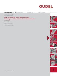
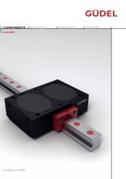
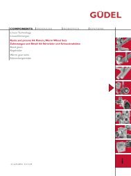
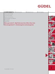
COMPONENTSMODULESROBOTICSSYSTEMSLinear TechnologyLinearführungenRacks and pinionsZahnstangen und RitzelBevel gearsKegelräderWorm gear units: <strong>07</strong> – High Performance Servo Worm Gear UnitsSchneckengetriebe: <strong>07</strong> – <strong>Hochleistungs</strong>-<strong>Servoschneckengetriebe</strong>d,f,e/05.08/nr 0112129i
GÜDEL AGIndustrie NordCH-4900 LangenthalSwitzerlandphone +41 62 916 91 91fax +41 62 916 91 50eMail info@ch.gudel.comwww.gudel.comGÜDEL GmbHCarl-Benz-Strasse 5D-63674 AltenstadtGermanyphone +49 6047 9639 0fax +49 6047 9639 90eMail info@de.gudel.comwww.gudel.comGÜDEL Inc.4881 Runway Blvd.US-Ann Arbor, MI 48108USAphone +1 734 214 0000fax +1 734 214 9000eMail info@us.gudel.comwww.gudel.comALL LOCAL REPRESENTATIONS SEE:WWW.GUDEL.COM/GOLOCAL
Einführung Introduction IntroductionDer vorliegende Katalog umfasst die Komponentender Linear- und Antriebstechnik. DerInhalt widerspiegelt die Erfahrung von mehr als5 Jahrzehnten der Entwicklung und Fertigungvon Längsführungen,Verzahnungen undGetriebebau.Das nach ISO 9001: 2000 aufgebaute Qualitätssystem,eine grosse Lagerhaltung und ein weltweitesVertriebsnetz garantieren einen optimalenKundennutzen.Das umfangreiche Standardprogramm ermöglichteinen schnellen Zugriff auf alleKomponenten.Ein erfahrenes Ingenieurteam hilft Ihnen bei derAuswahl, erarbeitet mit Ihnen Einbauvorschlägeund optimiert Ihren Anwendungsfall.AuchSonderteile nach Ihren Zeichnungen stellen wirgerne für Sie her.Sprechen Sie mit uns!Le catalogue suivant comprend les composantsde la technique linéaire et d'entraînement. Lecontenu reflète l'expérience de plus de 5 décenniesde développement et de fabrication deguides longitudinaux, de dentures et de constructiond'engrenages.Le système de qualité élaboré selonISO 9001: 2000, un stock important et unréseau de distribution mondial garantissent auclient un profit optimal.La riche gamme standard permet un accès rapideà tous les composants.Une équipe d'ingénieurs expérimentés vousaidera à choisir, travaillera avec vous des projetsde montage et optimisera votre cas d'application.Nous fabriquerons également des piècesspéciales pour vous selon vos dessins.Parlez-nous de vos applications!This catalogue covers all the components ofthe linear and drive technology. Its contentreflects the experience of more than 5 decadesin the development and manufacture of linearguides, gears and gearboxes.A quality system based on ISO 9001: 2000, alarge inventory and a global distribution networkguarantee optimal benefits to the customer.The extensive standard programme makes rapidaccess to all components possible at all times.An experienced engineering team will help youin your selection, and assist you in drawing upinstallation proposals and in the optimisation ofyour application.We will also be pleased to manufacture customcomponents to your own drawings. Call us!Qualitätskontrolle Production et qualité Quality controlUm die hohen Qualitätsanforderungen unsererKundschaft zu erfüllen, werden die Module aufmodernsten Werkzeugmaschinen in eigenenWerken gefertigt. Die Qualitätskontrolle geschiehtgemäss ISO 9001 als Erststück- undStichprobenkontrolle.Dies garantiert unserer Kundschaft den Erwerbeines qualitativ hochwertigen Produktes.Pour satisfaire les exigences de notre clientèle,les modules sont fabriqués dans nos propresusines par des machines modernes.Le contrôle de qualité est fait suivant les exigencesde la norme ISO 9001.Tous ces efforts garantissent à notre clientèleun produit de haute qualité.To meet the high requirements of our clients,the modules are manufactured in our factoriesby modern machine tools. Quality control iscarried out in accordance with ISO 9001.This guarantees our clients a continuous highproduct quality.00.D
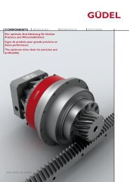
<strong>Hochleistungs</strong>-Servogetriebe Servoréducteur à haute performance High performance servo Gear UnitsDie AE-Baureihe kompakter <strong>Hochleistungs</strong>-<strong>Servoschneckengetriebe</strong> wird in 6 Baugrössenund Übersetzungen von 2:1 bis 24:1 hergestellt.Sie ist geeignet wo ein Höchstmass an Dynamikund Zuverlässigkeit gefordert wird.Die Exzenterflansche der Abtriebslagerungerlauben ein einfaches Ein- und Nachstellen desVerzahnungsspiels. Die Spezialkupplung an derEintriebsseite und die Schrumpfscheibe an derAbtriebsseite gewährleisten einen spielfreienKraftfluss.Unsere Ingenieure, denen entsprechendeRechnungsprogramme zur Verfügung stehen,helfen Ihnen gerne Ihren Anwendungsfall zuoptimieren.La gamme des Servoréducteurs compacts detype AE est fabriquée en 6 tailles avec des rapportsde réduction allant de 2:1 à 24:1. Ils sontrecommandes où un grand rendement et unegrande fiabilité sont nécessaires.Les brides excentriques des paliers de sortiepermettent de régler et derattraper de manière simple le jeu entre la viset la roue. L’accouplement au niveau de l’entréemoteur ainsi que la jonction de serrage auniveau de l’arbre de sortie permettent degarantir une transmission de puissance exemptde jeu.De plus nos ingénieurs, à l’aide de programmesde calcule sont à votredisposition afin d’optimiser vos applications.The AE-range of compact servo worm gearunits are manufactured in 6 model sizes, withreductions from 2:1 to 24:1.They are suitablefor use when a high efficiency and reliability arerequired.The eccentric flanges of the hollow outputshaft permit a simple setting and readjusting ofthe worm and wheel backlash.The drive couplingon the input shaft and a tension set onthe hollow output shaft guarantee a powertransmission torsion free and without backlash.Our engineers are equipped with calculationprograms and will be glad to help you to findthe right product for your application.Bild 1Bild 1Testing of gear boxes<strong>07</strong>.00
INHALTSVERZEICHNISTABLE DES MATIÈRES / CONTENTPRODUKTÜBERSICHT Gamme de produits Product overview <strong>07</strong>.02BAUKASTEN Le système modulaire The modular system <strong>07</strong>.03AUSWAHLTABELLE Sélection du Réducteur standard Selection of standard worm gear unit <strong>07</strong>.04BAUGRÖSSEN 030 Tailles de fabrication 030 Sizes 030 <strong>07</strong>.06BAUGRÖSSEN: 045 Taille de fabrication: 045 Size: 045 <strong>07</strong>.08BAUGRÖSSEN: 060 Taille de fabrication: 060 Size: 060 <strong>07</strong>.10BAUGRÖSSEN: 090 Taille de fabrication: 090 Size: 090 <strong>07</strong>.12BAUGRÖSSEN: 120 Taille de fabrication: 120 Size: 120 <strong>07</strong>.14BAUGRÖSSEN: 180 Taille de fabrication: 180 Size: 180 <strong>07</strong>.16BERECHNUNGSBEISPIEL Exemple de calcul Calculation example <strong>07</strong>.18WARTUNG Entretien Maintenance <strong>07</strong>.19EINBAU- UND AUSBAU Montage Assembly <strong>07</strong>.20MOTOREN APPLIKATIONEN Applications des moteurs Applications of motors <strong>07</strong>.22ANWENDUNGEN Exemple d’application Sample application <strong>07</strong>.29<strong>07</strong>.01
PRODUKTÜBERSICHTGAMME DES PRODUITSPRODUCT OVERVIEW<strong>Hochleistungs</strong>-Schneckengtriebe Réducteurs à haute performance Worm gear unit<strong>07</strong>.06–<strong>07</strong>.17 <strong>07</strong>.06–<strong>07</strong>.17 <strong>07</strong>.06–<strong>07</strong>.15<strong>07</strong>.06–<strong>07</strong>.17 <strong>07</strong>.06–<strong>07</strong>.17<strong>07</strong>.06–<strong>07</strong>.15<strong>07</strong>.06–<strong>07</strong>.17 <strong>07</strong>.06–<strong>07</strong>.17<strong>07</strong>.06–<strong>07</strong>.15 <strong>07</strong>.06–<strong>07</strong>.15<strong>07</strong>.02
BAUKASTENLE SYSTÈME MODULAIRETHE MODULAR SYSTEMDie AE-Baureihe kompakter <strong>Hochleistungs</strong>-<strong>Servoschneckengetriebe</strong> werden in 5 Baugrössenund 10 Untersetzungen hergestellt. DieBaugrösse ist identisch mit dem Achsabstand.La gamme des servoréducteurs compacts de typeAE est fabriquée suivant 5 tailles avec des rapportsde réduction allant de 2:1 a 24:1. La taille correspondà l'entraxe du servoréducteur.The AE-range of compact high performancegearboxes is available in 5 model sizes and 10standard ratios. The gearbox size is identical tothe centreline distance.BaugrössenTaille 030 045 060 090 120 180SizeÜbersetzungRatio 2:1 3:1 4:1 5:1 6:1 8:1 10:1 13 1 /3:1 16:1 24:1ZahnspielJeu axialBacklash3 – 6 Arc MinDas grosse Untersetzungsprogramm erlaubteine optimale Abstimmung der <strong>Hochleistungs</strong>-Schneckengetriebe mit dem Servoantriebspaket.Die Zahnungen der Getriebe sind nach DIN3975/76 ausgelegt und so optimiert, dass eineSpieleinstellung der Verzahnung über dieAbtriebs-Exzenterflansche erfolgen kann.Die Gehäuse sind allseitig bearbeitet und habenBefestigungs- sowie Gewindebohrungen.Kühlrippen garantieren einen optimalen Abflussder Wärme.Die synthetische Schmierung gewährleistetlange Lebensdauer sowie hohen Wirkungsgradund grosse Laufruhe.Eine Spezialkupplung an der Eintriebsseite undeine Schrumpfscheibenkupplung an der Abtriebsseitegarantieren einen spielfreienKraftfluss und den Anbau eines beliebigenMotors.Die Auswahl- und Belastungstabellen sind aufSeite <strong>07</strong>.04 für Getriebe und Seite 03.03 fürZahnstangen und Ritzel.Für Auslegungs- und Berechnungsbeispiele verweisenwir auf Seiten <strong>07</strong>.16.La grande variété de rapports de réductionspermet d'obtenir un choix optimum avec unsystème asservis.Les couples roues et vis et la denture sont réalisésselon la norme DIN 3975/76 et le rattrapagedu jeu se fait avec les brides excentriques despaliers de sortie. Le carter est usiné sur tous lescôtés et les trous de fixation permettent différentespositions de montage. La conceptiondes aillettes permet d’obtenir une excellentedissipation thermique.La lubrification avec une huile synthétique garantitun grand rendement et un fonctionnementsilencieux.L'accouplement de l'entrée moteur ainsi que lajonction de serrage ou niveau de l'arbre de sortiepermettent une transmission de puissanceexempt de jeu et le montage de tous types demoteurs.Les tableaux de charge des réducteurs sont à lapage <strong>07</strong>.04 et pour les crémaillères, pignons page03.03. Un exemple de calcul est présenté enpage <strong>07</strong>.16.The large range of gearbox ratio's allows tomatch the exact requirement of the ServoDrive system.Worm and wormwheel are manufactured toDIN 3975/76 and the geometrical dimensions ofthe tooth is optimized so the backlash can beadjusted by using the eccentric hub of the outputflanges.The casings are fully machined and with its manyfixing bores and tapped holes allowing mountingin any positions.The integrated fins of the housingdissipate the heat and maintain an optimumrunning temperature.The synthetic special oil for lubrication ensures ahigh degree of efficiency and smooth operation.A special clutch on the input and a discplate couplingon the output shaft guarantee largely torsionand backlash free connections and mountingof any type of motors.The selections- and load tables are on page<strong>07</strong>.04 for gear boxes and on page 03.03 for racksand pinions.Calculation example is on page <strong>07</strong>.16.<strong>07</strong>.03
WAHL DES SERVO SCHNECKENGETRIEBESSÉLECTION DU RÉDUCTEUR À HAUTE PERFORMANCESELECTION OF WORM GEAR DRICE UNITDie Getriebe sind für den Einsatz mit Dreh- undGleichstrom-Servomotoren ausgelegt. Die Exzenterflanscheder Abtriebslagerung erlaubenein einfaches Ein- und Nachstellen des Verzahnungsspiels.Die Einheiten werden im Werk mit einem Verzahnspielvon < 6’ eingestellt.Les réducteurs ont été developpés pour êtreutilisés avec des moteurs d'asservissement. Labride excentrique du palier de sortie premet derégler et de rattraper de manière facile le jeuaxial de la denture.Sortie d'usine les réducteurs sont réglés avec unjeu de < 6’.These high performance worm gearboxes wereespecially developed for use in high performanceServo-Driven Systems.The backlash is adjustableand is set by rotating the two eccentric flangeslocated on either side of the gearbox housing.The units are set up in the factory with a backlash< 6’.Richtlinien für die GetriebewahlDie in der Tabelle aufgeführten AbtriebsmomenteT2N (Nm) sind gültig für den Einsatzim stossfreien Servo-Betrieb bei 20°C Umgebungstemperatur.Bei höheren Belastungen sinddie Tabellenwerte mit den nachstehenden Faktorenzu korrigieren.Sélectionner un réducteurLes couples indiquées dans le tableau,T2N (Nm)sont valables pour des systèmes d'asservissement,fonctionnant sans chocs et à 20°C de températureambiante. Pour d'autres conditions lesvaleurs sont à corriger avec les coefficients selontableaux.Selecting a unitThe nominal torque T2N (Nm) is valid for servoapplications that run under normal shock freeoperations and at an ambient temperature of20°C. Other conditions have to be corrected byfactors shown below.Zusätzlich zu den erwähnten Betriebsfaktorenist ein Sicherheitsfaktor einzurechnen, der IhrenErfahrungen und den anwendungsspezifischenSicherheitsanforderungen entspricht. Baugrössen120 und 180: Bei Eintriebs-Drehzahlen über1500 min -1 und gleichzeitiger Einschaltdauerüber 80%, bitten wir Sie mit Güdel Kontakt aufzunehmen.Pour toutes applications paticulières il est nécessairede mettre un coefficient de sécurité supplémentaireaux coefficients déjà défini dans letableau, celui-ci correspondant à chacune desapplications client. Tailles 120 et 180: En cas devitesse de rotation à l’entrée supérieure à 1500min -1 et un cycle de fonctionnement supérieur à80% veuillez contacter Güdel s.v.p.For specific applications it may be necessary toconsider a safety factor, in addition to the factorsalredy mentioned in the catalogue. This factormust be based on the customer’s experienceand any regulations specific to the application.Sizes 120 and 180: In the case of an input speedhigher than 1500 min -1 with a duty cycle higherthan 80%, please contact Güdel.T2N Mech. ≥ T2 · fb · fA T2N Therm. ≥ T2 · ft · fED Beide Gleichungen müssen erfüllt sein / both required /Betriebsfaktor / Coefficient de marche / Service coefficientAntrieb Polynomia Standard Servo / FU/VFD AC-Motor ExternalSinus 2Output-shockfB 1.0 1.1 1.25 1.4 1.6Anlauffaktor / Coefficient de démarrage / Starting factorAnlaufhäufigkeit / Fréquence de démarrage / Starting frequency ≤60/h ≤360/h ≤1200/h ≤3600/hfA 1.0 1.1 1.2 1.3Temperaturfaktor / Coefficient de température / Temperature factorUmgebungstemperatur / Température ambiante / Ambient temperature ≤10° C ≤20° C ≤30° C ≤40° C ≤50° Cft 0.85 1.0 1.2 1.5 1.9Einschaltdauerfaktor / Coefficient de service / Duty factorEinschaltdauer / Cycle de service / Duty cycle ≤25% ≤40% ≤60% ≤70% ≤100%fED 0.7 0.9 1.1 1.2 1.4T2 (Nm): Drehmoment der Maschine / Couple de la machine / Required torque for driven machineZulässige Belastungen auf dieAbtriebswelleTreten neben hohen Radialkräften gleichzeitigAxialkräfte auf, erbitten wir um Rückfrage.Die Abtriebsglocken mit der Ritzellagerungmüssen konstruktiv abgestützt werden. SieheFig. ➀.Charges admissibles au niveau de l’arbrede sortieSi les charges radiales et axiales sont trèsimportantes nous vous prions de nous consulter.Il est nécessaire de considérer dans la constructionun support pour le palier du pignonde la bride de sortie voir Fig. ➀.Permissible output shaft loadsIn case of very high radial and axial loads pleasecontact us.The output flange with the pinion bearing mustbe supported see Fig. ➀.Typ AE 030 AE 045 AE 060 AE 090 AE 120 AE 180L1 (mm) 78 104 126 165 268 340F1Max (N) 1 400 3 000 4 500 9 750 24 000 60 000L2 (mm) 59 78 98 133 182 240F2Max (N) 900 1 700 3 450 7 500 12 500 15 000Fig. ➀.<strong>07</strong>.04
Leistungstabellen Tableau des caractéristiques Efficiency tablesn1 (min -1 )6000 4500 3000 1500 1000 500Typ i T2max P1 T2N η P1 T2N η P1 T2N η P1 T2N η P1 T2N η P1 T2N ηAE 030 2 35 1,97 4,9 0,79 1,72 5,9 0,81 1,39 7,4 0,84 0,91 10,0 0,86 0,68 11,3 0,86 0,40 12,9 0,853 2,05 7,8 0,79 1,76 9,2 0,82 1,40 11,2 0,84 0,88 14,4 0,86 0,65 16,0 0,86 0,37 17,9 0,844 1,89 9,4 0,78 1,61 11,0 0,81 1,25 13,3 0,83 0,77 16,7 0,85 0,56 18,3 0,85 0,32 20,1 0,835 1,54 9,4 0,77 1,33 11,0 0,78 1,02 13,1 0,81 0,62 16,2 0,83 0,44 17,5 0,83 0,25 19,2 0,816 1,20 8,6 0,75 1,02 9,9 0,76 0,79 11,7 0,77 0,47 14,3 0,80 0,34 15,5 0,81 0,18 16,9 0,808 1,10 10,1 0,72 0,94 11,6 0,73 0,72 13,7 0,74 0,42 16,6 0,77 0,30 17,9 0,77 0,17 19,4 0,7610 0,88 9,5 0,68 0,74 10,9 0,69 0,57 12,8 0,71 0,33 15,4 0,73 0,24 16,6 0,74 0,13 17,9 0,7413 1 /3 0,72 9,4 0,62 0,59 10,8 0,65 0,44 12,6 0,67 0,26 15,1 0,68 0,19 16,2 0,68 0,10 17,5 0,6716 0,74 10,5 0,56 0,59 12,0 0,60 0,44 14,0 0,62 0,26 16,9 0,64 0,18 18,1 0,65 0,10 19,5 0,6324 0,57 10,3 0,47 0,45 11,8 0,51 0,34 13,7 0,53 0,20 16,4 0,54 0,14 17,6 0,55 0,08 19,0 0,54AE 045 2 120 5,95 16,2 0,85 5,41 20,0 0,87 4,63 26,0 0,88 3,29 37,4 0,89 2,57 43,8 0,89 1,57 52,7 0,883 6,34 26,0 0,86 5,69 31,6 0,87 4,76 40,3 0,89 3,25 55,4 0,89 2,48 63,3 0,89 1,47 73,9 0,884 5,90 32,0 0,85 5,23 38,5 0,87 4,32 48,3 0,88 2,87 64,8 0,89 2,17 73,1 0,88 1,27 83,9 0,875 4,88 32,4 0,84 4,28 38,7 0,85 3,48 48,1 0,87 2,27 63,4 0,88 1,70 71,0 0,87 0,98 80,5 0,866 3,83 29,6 0,81 3,33 35,2 0,83 2,67 43,4 0,85 1,71 56,5 0,86 1,27 62,9 0,86 0,73 70,8 0,858 3,53 35,2 0,79 3,04 41,6 0,81 2,42 51,0 0,83 1,55 65,8 0,84 1,14 72,9 0,84 0,65 81,7 0,8210 2,79 33,2 0,75 2,39 39,2 0,77 1,89 47,8 0,80 1,18 61,3 0,81 0,87 67,7 0,81 0,50 75,5 0,7913 1 /3 2,22 33,0 0,70 1,88 38,8 0,73 1,48 47,2 0,75 0,92 60,3 0,77 0,68 66,4 0,77 0,39 73,9 0,7516 2,19 36,8 0,66 1,82 43,3 0,70 1,44 52,7 0,72 0,89 67,2 0,74 0,66 74,0 0,73 0,35 75,0 0,7124 1,63 36,1 0,58 1,35 42,5 0,62 1,06 51,6 0,64 0,65 65,6 0,66 0,48 72,2 0,65 0,27 77,9 0,63AE 060 2 300 12,65 35 0,88 11,73 44 0,89 10,35 59 0,90 7,75 89 0,90 6,23 1<strong>07</strong> 0,90 3,96 135 0,893 13,65 58 0,88 12,52 71 0,89 10,82 93 0,90 7,79 135 0,91 6,11 158 0,90 3,75 192 0,894 12,78 71 0,88 11,61 88 0,89 9,89 113 0,90 6,94 159 0,90 5,38 184 0,90 3,24 219 0,885 10,56 73 0,87 9,51 89 0,88 8,01 113 0,89 5,51 157 0,89 4,23 180 0,89 2,52 211 0,886 8,24 67 0,85 7,36 81 0,87 6,13 103 0,88 4,15 140 0,89 3,16 160 0,88 1,87 186 0,878 7,56 80 0,83 6,72 96 0,84 5,56 121 0,86 3,74 164 0,86 2,83 186 0,86 1,67 215 0,8410 5,93 75 0,80 5,24 91 0,82 4,30 114 0,83 2,86 153 0,84 2,16 173 0,84 1,27 199 0,8213 1 /3 4,69 75 0,75 4,11 90 0,78 3,34 113 0,80 2,20 151 0,81 1,66 170 0,81 0,98 195 0,7816 4,54 84 0,72 3,97 101 0,75 3,23 126 0,77 2,13 168 0,78 1,61 190 0,77 0,86 195 0,7424 3,37 82 0,64 2,91 99 0,67 2,34 124 0,69 1,53 165 0,70 1,16 185 0,70 0,66 202 0,67AE 090 2 900 32,4 126 0,91 29,6 174 0,92 23,7 279 0,92 19,8 350 0,92 13,4 469 0,923 35,3 206 0,92 31,7 279 0,92 24,4 432 0,93 19,9 528 0,92 12,9 679 0,924 33,0 257 0,92 29,3 343 0,92 22,0 518 0,92 17,7 624 0,92 11,3 784 0,915 27,2 262 0,91 23,9 348 0,92 17,6 516 0,92 14,0 615 0,92 8,8 761 0,916 21,0 241 0,90 18,3 318 0,91 13,3 466 0,91 10,5 551 0,91 6,5 674 0,908 19,2 288 0,88 16,6 377 0,89 12,0 547 0,90 9,4 644 0,89 5,8 782 0,8810 14,9 273 0,86 12,8 356 0,88 9,1 513 0,88 7,2 601 0,88 4,4 726 0,8713 1 /3 11,5 272 0,83 9,8 354 0,85 7,0 5<strong>07</strong> 0,85 5,5 592 0,85 3,3 712 0,8416 11,1 303 0,81 9,5 395 0,82 6,7 565 0,83 5,3 660 0,82 2,9 700 0,8024 7,9 298 0,74 6,7 388 0,76 4,7 553 0,77 3,7 645 0,76 2,1 727 0,74AE 120 2 2300 69,9 276 0,93 65,1 387 0,93 54,3 648 0,94 46,7 836 0,94 33,0 1177 0,933 76,9 457 0,93 70,5 631 0,94 56,9 1020 0,94 47,8 1284 0,94 32,4 1732 0,934 72,5 573 0,93 65,8 783 0,93 51,9 1237 0,94 42,9 1534 0,94 28,4 2018 0,935 59,8 588 0,93 53,9 798 0,93 41,8 1241 0,93 34,2 1523 0,93 22,3 1969 0,936 46,3 543 0,92 41,4 733 0,93 31,7 1126 0,93 25,8 1371 0,93 16,6 1752 0,928 42,2 650 0,91 37,6 873 0,91 28,5 1329 0,91 23,1 1609 0,91 14,7 2038 0,9010 32,6 617 0,89 28,9 826 0,90 21,7 1248 0,90 17,5 1505 0,90 11,1 1895 0,8913 1 /3 25,1 616 0,87 22,1 822 0,88 16,5 1237 0,88 13,3 1487 0,88 8,4 1863 0,8716 24,1 688 0,84 21,2 918 0,85 15,8 1380 0,86 12,7 1658 0,85 7,1 1824 0,8424 16,9 677 0,79 14,8 903 0,80 11,0 1353 0,80 8,8 1622 0,80 5,3 1900 0,78AE 180 6 8000 99.0 1798 0.95 80.6 2938 0.95 68.2 3726 0.95 46.7 5091 0.958 89.8 2150 0.94 72.5 3486 0.94 61.0 4396 0.94 41.4 5950 0.9410 68.9 2041 0.93 55.2 3289 0.94 46.2 4131 0.94 31.2 5553 0.9313 1 / 3 52.5 2037 0.91 41.8 3268 0.92 34.9 4093 0.92 23.5 5473 0.9216 49.8 2277 0.90 39.7 3649 0.90 33.1 4566 0.90 22.2 6100 0.9024 34.2 2241 0.86 27.1 3583 0.87 22.6 4477 0.87 15.2 5963 0.86i:Ab Lager / du stock / ex stockn 1 (min -1 ) : Eintriebsdrehzahl / Vitesse d’entrée / input speedT 2Max (Nm) : Max. Drehmoment bei Not – Aus / Couple max. en cas d’arrêt d’urgence / Max. torque in case of emergency stop.T 2N (Nm) : Nenndrehmoment am Abtrieb / Couple de sortie nominale / Nominal output torqueP 1 (kW) : Eintriebsleistung / Puissance d’entrée / Input powerη : Wirkungsgrad / Rendement / Efficiency<strong>07</strong>.05
BAUGRÖSSE 030TAILLE 030SIZE 030<strong>Hochleistungs</strong>-Schneckengetriebe Réducteur à haute performance Worm gear unita = 30 mm20 < L < 33L ausgelegt für Flansch mit t 1 = 12mmL sur la base d’une épaisseur de flange t 1 = 12mmL based on a flange thickness t 1 = 12mmPos. ➄ Pos. ➃ Pos. ➀ Pos. ➅AE 030/LDIN 912 8.8Fig. ➁Fig. ➀AE 030/RPos. ➀ Getriebe / Réducteur / Worm gear unitType Part No. Ratio InertiaL i J red (10 -7 kg m 2 ) m (kg)AE 030/L 403 000 2 : 1 138 1.6AE 030/R 403 008 3 : 1 69AE 030/S 403 009 4 : 1 455 : 1 346 : 1 288 : 1 2210 : 1 1913 1 ⁄3 :1 1716 : 1 1624 : 1 15i: ab Lager / sur stock / from stockAE 030/SPos. ➃ Flansch / Bride / FlangePart No. Fig. S r F t1 t2 D M m (kg)403 083 ➀ 40 63 55 12 4 — M4 0.2403 090 ➀ 50 70 60 12 4 — M5403 081 ➀ 50 95 82 12 4 — M6403 082 ➀ 60 75 70 12 4 — M5403 091 ➀ 60 90 75 12 4 — M5403 086 ➀ 70 85 80 12 4 — M6403 092 ➀ 70 90 80 12 4 — M6403 080 ➀ 80 100 92 12 4 — M6403 087 ➀ 80 100 90 21 8 — M6 0.3403 085 ➁ 60 75 — 12 4 90 5,8403 084 ➁ 70 85 — 12 4 105 7<strong>07</strong>.06
Pos. ➄ Kupplung / Accouplement /CouplingFig. ➀InertiaPart No. Fig. d J (10 -6 kg m 2 ) T1max (Nm) MA (Nm) m (kg)403 023 ➀ 8 11.5 3.4 M3x16 1.37 0.1403 022 ➀ 9 11.5 3.8 M3x16403 025 ➀ 10 11.0 4.0 M3x16403 021 ➀ 11 11.0 4.7 M3x16403 020 ➀ 14 11.0 6.0 M3x16T1max: maximal übertragbares Moment der Kupplung / Couple max. de l’accouplement / Maximumtorque of couplingMA: Anziehdrehmoment / Couple de serrage / Tightening torquePos. ➅ Schrumpfscheiben-Kupplung / Jonction arbre-moyeu /Tension setInertiaPart No. J (10 -6 kg m 2 ) T2max (Nm) m (kg)403 031 36 67 0.12M A5 NmT2max: maximal übertragbares Moment der Kupplung / Couple max. del’accouplement / Maximum torque of couplingJ red = J / i 2Zubehör Accessoires AccessoriesPos. ➁ Abtrieb mit Ritzel / Bride de sortie avec pignon /Output flange with pinionPart No. Module p z D 0 D k D 1 L 4 L 5 L 6 J m (kg)403 050 0.6366 2.0 30 19.10 20.4 47 9.5 38 50 38 0.35403 052 1.0 3.142 25 25 27 47 9.5 38 50 40 0.4p (mm):Teilung / pas / pitch J (10 -6 kg m 2 ): Inertia J red = J / i 2Pos. ➂ Distanzstücke / Entretoise / Spacer Part No. Mat. L 7 m (kg)403 060 Alu 19 0.2Bestellbeispiel Exemple de commande Ordering examplePos. ➀ AE 030/L: 403 000 i: 8:1ZubehörPos. ➃403 081Pos. ➁Pos. ➄403 021Pos. ➂Pos. ➅—403 050403 060Angaben für speziellen Flanschund KupplungSpécification pour la bride desortie et l’accouplement spécialeSpecification for special flangeand couplingd : [mm]L : [mm]S : [mm]r : [mm]F : [mm]ØM :M : alternativ M…t :[mm][mm][mm]MotorD : alternativ [mm]<strong>07</strong>.<strong>07</strong>
BAUGRÖSSE 045TAILLE 045SIZE 045<strong>Hochleistungs</strong>-Schneckengetriebe Réducteur à haute performance Worm gear unita = 45 mm33 ≤ L2 < 4320 < L1 < 33L ausgelegt für Flansch mit t 1 = 14mmL sur la base d’une épaisseur de flange t 1 = 14mmL based on a flange thickness t 1 = 14mmPos. ➄ Pos. ➃ Pos. ➀ Pos. ➅AE 045/LDIN 912 8.8Fig. ➁Fig. ➀Pos. ➀ Getriebe / Réducteur / Worm gear unitType Part No. Ratio InertiaL 1 L 2 i J red (10 -6 kg m 2 ) m (kg)AE 045/L 404 500 404 510 2 : 1 97 3,5AE 045/R 404 508 404 518 3 : 1 47AE 045/S 404 509 404 519 4 : 1 295 : 1 216 : 1 168 : 1 1210 : 1 1013 1 ⁄3 :1 816 : 1 724 : 1 6i: ab Lager / sur stock / from stockAE 045/RAE 045/SPos. ➃ Flansch / Bride / FlangePart No. Fig. S r F t1 t2 D M m (kg)404 590 ➀ 50 70 70 14 4 — M5 0.25404 581 ➀ 50 95 82 14 4 — M6404 582 ➀ 60 75 70 14 4 — M5404 592 ➀ 60 90 75 14 4 — M5404 585 ➀ 70 85 80 14 4 — M6404 593 ➀ 70 90 80 14 4 — M6404 580 ➀ 80 100 92 14 4 — M6404 594 ➀ 80 100 90 18 8 — M6404 583 ➀ 95 115 100 14 4 — M8404 595 ➀ 110 145 120 14 4 — M8 0.3404 587 ➀ 95 115 105 23 11 — M8404 584 ➁ 70 85 — 14 4 105 ø7404 586 ➁ 80 100 — 14 4 120 ø7<strong>07</strong>.08
Pos. ➄ Kupplung / Accouplement /CouplingFig. ➀InertiaPart No. Fig. d J (10 -6 kg m 2 ) T1max (Nm) MA (Nm) m (kg)404 523 ➀ 9 28 6.7 M4x16 3.1 0.15404 522 ➀ 11 27 8.2 M4x16404 521 ➀ 14 26 10.4 M4x16404 525 ➀ 16 26 12.0 M4x16404 520 ➀ 19 25 14.2 M4x16T1max: maximal übertragbares Moment der Kupplung / Couple max. de l’accouplement / Maximumtorque of couplingMA: Anziehdrehmoment / Couple de serrage / Tightening torquePos. ➅ Schrumpfscheiben-Kupplung / Jonction arbre-moyeu /Tension setInertiaPart No. J (10 -6 kg m ) 2 T2max (Nm) m (kg)404 531 90 142 0.2M A6.5 NmT2max: maximal übertragbares Moment der Kupplung / Couple max. del’accouplement / Maximum torque of couplingJ red = J / i 2Zubehör Accessoires AccessoriesPos. ➁ Abtrieb mit Ritzel / Bride de sortie avec pignon /Output flange with pinionPart No. Module p z D 0 D k D 1 L 4 L 5 L 6 J m (kg)404 550 1.5915 5.0 20 31.83 35 60 11.5 43 59 109 1.7404 551 1.5915 5.0 20 31.83 35 60 14.5 43 69 111 1.7p (mm):Teilung / pas / pitch J (10 kg m ): Inertia -6 2 J red = J / i 2Pos. ➂ Distanzstücke / Entretoise / Spacer Part No. Mat. L 7 m (kg)404 560 ➀ Alu 19 0.25➀ Lieferung paarweise / Livraison par paire / Delivery in pairsonlyBestellbeispiel Exemple de commande Ordering examplePos. ➀ AE 045/L: 404 510 i: 5:1ZubehörPos. ➃404 581Pos. ➁Pos. ➄404 521Pos. ➂Pos. ➅404 530——Angaben für speziellen Flanschund KupplungSpécification pour la bride desortie et l’accouplement spécialeSpecification for special flangeand couplingd : [mm]L : [mm]S : [mm]r : [mm]F : [mm]ØM :M : alternativ M…t :[mm][mm][mm]MotorD : alternativ [mm]<strong>07</strong>.09
BAUGRÖSSE 060TAILLE 060SIZE 060<strong>Hochleistungs</strong>-Schneckengetriebe Réducteur à haute performance Worm gear unita = 60 mm50 ≤ L 3 < 6540 ≤ L 2 < 5025 < L 1 < 40L ausgelegt für Flansch mit t 1 = 14mmL sur la base d’une épaisseur de flange t 1 = 14mmL based on a flange thickness t 1 = 14mmPos. ➄ Pos. ➃ Pos. ➀ Pos. ➅AE 060/LDIN 912 8.8Fig. ➁Fig. ➀AE 060/RPos. ➀ Getriebe / Réducteur / Worm gear unitType Part No. Ratio InertiaL 1 L 2 L 3 i J red (10 -6 kg m 2 ) m (kg)AE 060/L 406 000 406 010 406 015 2 : 1 416 7.7AE 060/R 406 008 406 018 406 016 3 : 1 199AE 060/S 406 009 406 019 406 017 4 : 1 1225 : 1 876 : 1 678 : 1 4910 : 1 4013 1 ⁄3 :1 3316 : 1 30i: ab Lager / sur stock / from stock 24 : 1 27Pos. ➃ Flansch / Bride / Flange<strong>07</strong>.10AE 060/SPart No. Fig. S r F t1 t2 D M m (kg)406 085 ➀ 80.0 100 92 14 5 — M6 0.5406 090 ➀ 95.0 115 100 14 5 — M6406 084 ➀ 95.0 115 105 14 5 — M8406 083 ➀ 95.0 130 115 14 5 — M8406 082 ➀ 95.0 165 140 14 5 — M10406 089 ➀ 110.0 130 116 14 5 — M8406 091 ➀ 110.0 145 120 14 5 — M8406 092 ➀ 110.0 145 130 20 11 — M8406 093 ➀ 130.0 165 142 20 11 — M10406 081 ➀ 110.0 165 140 14 5 — M10406 080 ➀ 130.0 165 140 14 5 — M10406 086 ➁ 110.0 130 — 14 5 160 ø9406 088 ➁ 130.0 165 — 14 5 185 M10
Pos. ➄ Kupplung / Accouplement /CouplingFig. ➀Fig. ➁InertiaPart No. Fig. d J (10 -6 kg m 2 ) T1max (Nm) MA (Nm) m (kg)406 021 ➀ 19 83 32.8 M6x20 10.5 0.3406 024 ➀ 22 80 38.0 M6x20406 020 ➀ 24 79 41.5 M6x20406 026 ➁ 28 294 41.9 M4x16 3.12 0.45406 023 ➁ 32 271 47.9 M4x16T1max: maximal übertragbares Moment der Kupplung / Couple max. de l’accouplement / Maximumtorque of couplingMA: Anziehdrehmoment / Couple de serrage / Tightening torqueFig. ➁ nur mit L3 einsetzbar / Fig. ➁ impose longueur L3 / Fig. ➁ requires lenght L3.Pos. ➅ Schrumpfscheiben-Kupplung / Jonction arbre-moyeu /Tension setInertiaPart No. J (10 -6 kg m 2 ) T2max (Nm) m (kg)406 031 200 300 0.3M A6.5 NmT2max: maximal übertragbares Moment der Kupplung / Couple max. del’accouplement / Maximum torque of couplingJ red = J / i 2Zubehör Accessoires AccessoriesPos. ➁ Abtrieb mit Ritzel / Bride de sortie avec pignon /Output flange with pinionPart No. Module p z D 0 D k D 1 L 4 L 5 L 6 J m (kg)406 050 2.381 7.5 20 47.75 52.5 72 19.5 53 80.5 3<strong>07</strong> 1.6406 052 3.1831 10.0 14 46.47 52.5 72 29.5 58 100 338 2.6406 051 3.1831 10.0 20 63.66 70.0 72 29.5 58 100 620 3.0p (mm):Teilung / pas / pitch J (10 -6 kg m 2 ): Inertia J red = J / i 2Pos. ➂ Distanzstücke / Entretoise / Spacer Part No. Mat. L 7 m (kg)406 060 ➀ Alu 19 0.25406 061 ➀ Alu 22 0.28➀ Lieferung paarweise / Livraison par paire / Delivery in pairsonlyBestellbeispiel Exemple de commande Ordering examplePos. ➀ AE 060/L: 406 008 i: 5:1ZubehörPos. ➃406 081Pos. ➁Pos. ➄406 021Pos. ➂Pos. ➅406 030——Angaben für speziellen Flanschund KupplungSpécification pour la bride desortie et l’accouplement spécialeSpecification for special flangeand couplingd : [mm]L : [mm]S : [mm]r : [mm]F : [mm]ØM :M : alternativ M…t :[mm][mm][mm]MotorD : alternativ [mm]<strong>07</strong>.11
BAUGRÖSSE 090TAILLE 090SIZE 090<strong>Hochleistungs</strong>-Schneckengetriebe Réducteur à haute performance Worm gear unita = 90 mm62 ≤ L2 < 8240 < L1 < 62L ausgelegt für Flansch mit t 1 = 18mmL sur la base d’une épaisseur de flange t 1 = 18mmL based on a flange thickness t 1 = 18mmDIN 912 8.8Pos. ➄ Pos. ➃ Pos. ➀ Pos. ➅AE 090/LFig. ➁Fig. ➀Pos. ➀ Getriebe / Réducteur / Worm gear unitType Part No. Ratio InertiaL1 L2 i J red (10 -5 kg m 2 ) m (kg)AE 090/L 409 000 409 010 2 : 1 308 21.0AE 090/R 409 008 409 018 3 : 1 147AE 090/S 409 009 409 019 4 : 1 915 : 1 656 : 1 518 : 1 3710 : 1 3013 1 ⁄ 3 :1 2516 : 1 23i: ab Lager / sur stock / from stock 24 : 1 21AE 090/RAE 090/SPos. ➃ Flansch / Bride / FlangePart No. Fig. S r F t1 t2 D M m (kg)409 090 ➀ 95.0 115 105 18 6 — M6 1.0409 085 ➀ 95.0 115 105 18 6 — M8409 084 ➀ 95.0 130 115 18 6 — M8409 089 ➀ 110.0 130 116 18 6 — M8409 091 ➀ 110.0 145 130 27 11 — M8409 083 ➀ 110.0 165 140 18 6 — M10409 092 ➀ 114.3 200 174 18 6 — M12409 082 ➀ 130.0 165 142 18 6 — M10409 094 ➀ 130.0 165 142 24 12 — M10409 080 ➀ 130.0 215 193 18 6 — M12409 081 ➀ 180.0 215 190 18 6 — M12409 093 ➀ 200.0 235 220 18 6 — M12409 086 ➁ 130.0 165 — 18 6 200 ø11409 087 ➁ 180.0 215 — 18 6 250 ø14409 088 ➁ 230.0 265 — 18 6 300 ø14<strong>07</strong>.12
Pos. ➄ Kupplung / Accouplement /CouplingFig. ➀Fig. ➁InertiaPart No. Fig. d J (10 -6 kg m 2 ) T1max (Nm) MA (Nm) m (kg)409 023 ➀ 19 469 64 M8x30 26.0 0.8409 022 ➀ 24 463 74 M8x30409 021 ➀ 28 454 86 M8x30409 020 ➀ 32 442 98 M8x30409 028 ➀ 35 420 1<strong>07</strong> M8x30409 024 ➁ 38 1162 131 M6x20 10.5 0.9409 025 ➁ 42 1096 145 M6x20T1max: maximal übertragbares Moment der Kupplung / Couple max. de l’accouplement / Maximumtorque of coupling / MA: Anziehdrehmoment / Couple de serrage / Tightening torqueFig. ➁ nur mit L2 einsetzbar / Fig. ➁ impose longueur L2 / Fig. ➁ requires lenght L2.Pos. ➅ Schrumpfscheiben-Kupplung / Jonction arbre-moyeu /Tension setInertiaPart No. J (10 -6 kg m 2 ) T2max (Nm) m (kg)409 031 1150 1250 0.86T2max: maximal übertragbares Moment der Kupplung / Couple max. deM Al’accouplement / Maximum torque of coupling12 NmJ red = J / i 2Zubehör Accessoires AccessoriesPos. ➁ Abtrieb mit Ritzel / Bride de sortie avec pignon /Output flange with pinionPart No. Module p z D 0 D k D 1 L 4 L 5 L 6 J m (kg)409 050 3.183 10 20 63.66 70 98 29.5 63 105 1784 4.0409 052 3.9789 12.5 14 58.09 66.05 98 40 63 121 1788 6.0409 051 3.9789 12.5 20 79.58 87.50 98 40 104.5 164.5 2828 10.0409 053 3.9789 12.5 20 79.58 87.50 98 40 104.5 170.5 2828 10.0p (mm):Teilung / pas / pitch J (10 -6 kg m 2 ): Inertia J red = J / i 2Pos. ➂ Distanzstücke / Entretoise / Spacer Part No. Mat. L 7 m (kg)409 060 ➀ Alu 24 0.45409 062 ➀ Alu 41 0.66➀ Lieferung paarweise / Livraison par paire / Delivery in pairs onlyBestellbeispiel Exemple de commande Ordering examplePos. ➀ AE 090/S: 409 019 i: 16:1ZubehörPos. ➃409 082Pos. ➁Pos. ➄409 021Pos. ➂Pos. ➅409 030——Angaben für speziellen Flanschund KupplungSpécification pour la bride desortie et l’accouplement spécialeSpecification for special flangeand couplingd : [mm]L : [mm]S : [mm]r : [mm]F : [mm]ØM :M : alternativ M…t :[mm][mm][mm]MotorD : alternativ [mm]<strong>07</strong>.13
BAUGRÖSSE 120TAILLE 120SIZE 120<strong>Hochleistungs</strong>-Schneckengetriebe Réducteur à haute performance Worm gear unita = 120 mm79 ≤ L3 < 11059 ≤ L2 < 7933 < L1 < 59L ausgelegt für Flansch mit t 1 = 20mmL sur la base d’une épaisseur de flange t 1 = 20mmL based on a flange thickness t 1 = 20mmDIN 912 8.8Pos. ➄ Pos. ➃ Pos. ➀ Pos. ➅AE 120/LFig. ➁Fig. ➀Pos. ➀ Getriebe / Réducteur / Worm gear unitType Part No. Ratio InertiaL1 L2 L3 i J red (10 -5 kg m 2 ) m (kg)AE 120/L 412 000 412 010 412 015 2 : 1 1310 45AE 120/R 412 008 412 018 412 016 3 : 1 620AE 120/S 412 009 412 019 412 017 4 : 1 3805 : 1 2706 : 1 2108 : 1 15010 : 1 12013 1 / 3 :1 10016 : 1 93i: ab Lager / sur stock / from stock 24 : 1 82Pos. ➃ Flansch / Bride / FlangeAE 120/RAE 120/SPart No. Fig. S r F t1 t2 D M m (kg)412 083 ➀ 110.0 165 140 20 6 — M10 1,0412 090 ➀ 114.3 200 174 20 6 — MI2412 082 ➀ 130.0 165 142 20 6 — MI0412 080 ➀ 130.0 215 192 20 6 — M12412 081 ➀ 180.0 215 190 20 6 — M12412 091 ➀ 200.0 235 220 20 6 — M12412 092 ➀ 230.0 265 250 20 6 — M12412 087 ➀ 250.0 300 260 20 6 — M16412 084 ➁ 180.0 215 — 20 6 250 ø14412 085 ➁ 230.0 265 — 20 6 300 ø14412 086 ➁ 250.0 300 — 20 6 350 ø18<strong>07</strong>.14
Pos. ➄ Kupplung / Accouplement /CouplingFig. ➀Fig. ➁Pos. ➅ Schrumpfscheiben-Kupplung / Jonction arbre-moyeu /Tension setM A12 NmPos. ➁ Abtrieb mit Ritzel / Bride de sortie avec pignon /Output flange with pinionInertiaPart No. Fig. d J (10 -6 kg m 2 ) T1max (Nm) MA (Nm) m (kg)412 021 ➀ 28 800 86 M8x30 26 1.0412 020 ➀ 32 800 98 M8x30412 023 ➀ 35 813 1<strong>07</strong> M8x30412 024 ➀ 38 760 117 M8x30412 025 ➀ 42 720 129 M8x30 1.1412 026 ➁ 48 2040 165 M6x25 10.5 1.2T1max: maximal übertragbares Moment der Kupplung / Couple max. de l’accouplement / Maximumtorque of coupling / MA: Anziehdrehmoment / Couple de serrage / Tightening torqueFig. ➁ nur mit L2, L3 einsetzbar / Fig. ➁ impose longueur L2, L3 / Fig. ➁ requires lenght L2, L3.InertiaPart No. J (10 -6 kg m 2 ) T2max (Nm) m (kg)412 031 3400 2500 1.5T2max: maximal übertragbares Moment der Kupplung / Couple max. del’accouplement / Maximum torque of couplingJ red = J / i 2Zubehör Accessoires AccessoriesPart No. Module p z D 0 D k D 1 L 4 L 5 L 6 J m (kg)412 051 3.9789 12.5 26 103.45 111.4 180 40 123 181 9422 24.0412 055 5.0930 16.0 20 101.86 112.1 180 50 123 213 10370 22.0412 053 6.3662 20.0 20 127.32 140.1 180 60 123 238 18350 27.0p (mm):Teilung / pas / pitch J (10 -6 kg m 2 ): Inertia J red = J / i 2Pos. ➂ Distanzstücke / Entretoise / Spacer Part No. Mat. L 7 m (kg)412 062 ➀ Alu 19 0.45412 060 ➀ Alu 34 0.60➀ Lieferung paarweise / Livraison par paire / Delivery in pairs onlyBestellbeispiel Exemple de commande Ordering examplePos. ➀ AE 120/L: 412 015 i: 5:1ZubehörPos. ➃412 080Pos. ➁—Pos. ➄412 021Pos. ➂—Pos. ➅412 030Angaben für speziellen Flanschund KupplungSpécification pour la bride desortie et l’accouplement spécialeSpecification for special flangeand couplingd : [mm]L : [mm]S : [mm]r : [mm]F : [mm]ØM :M : alternativ M…t :[mm][mm][mm]MotorD : alternativ [mm]<strong>07</strong>.15
BAUGRÖSSE 180TAILLE 180SIZE 180<strong>Hochleistungs</strong>-Schneckengetriebe Réducteur à haute performance Worm gear unita = 180 mmL ausgelegt für Flansch mit t 1 = 26mmL sur la base d’une épaisseur de flange t 1 = 26mmL based on a flange thickness t 1 = 26mm90 ≤ L2 < 12060 < L1 < 90Pos. ➄ Pos. ➃ Pos. ➀ Pos. ➅AE 180/LAE 180/RPos. ➀ Getriebe / Réducteur / Worm gear unitType Part No. Ratio InertiaL1 L2 i J red (10 -5 kg m 2 ) m (kg)AE 180 / L 418 000 418 010 6 : 1 1525 140AE 180 / R 418 008 418 018 8:1 109510 : 1 89513 1 /3 :1 74016 : l 680i: ab Lager / sur stock / from stock 24 :1 603Pos. ➃ Flansch / Bride / FlangePart No. Fig. S r F t1 t2 D M m (kg)418 081 ➀ 114.3 200 180 26 7 — M12 2.0418 082 ➀ 130.0 215 192 26 7 — M12 2.0418 080 ➀ 180.0 215 192 26 7 — M12 2.0418 083 ➀ 200.0 235 220 26 7 — M12 3.0418 084 ➀ 230.0 265 240 26 7 — M12 4.0418 085 ➀ 250.0 300 260 26 7 — M16 5.0418 086 ➀ 300.0 350 310 26 7 — M16 5.0<strong>07</strong>.16
Pos. ➄ Kupplung / Accouplement /CouplingFig. ➀InertiaPart No. Fig. d J (10 -6 kg m 2 ) T1max (Nm) MA (Nm) m (kg)418 020 ➀ 32 4080 240 M10x35 51 3.5418 021 ➀ 35 4050 265 M10x35418 022 ➀ 38 4030 280 M10x35418 023 ➀ 42 4000 315 M10x35418 024 ➀ 48 3865 360 M10x35418 025 ➀ 55 3670 400 M10x35T1max: maximal übertragbares Moment der Kupplung / Couple max. de l’accouplement / Maximumtorque of coupling / MA: Anziehdrehmoment / Couple de serrage / Tightening torquePos. ➅ Schrumpfscheiben-Kupplung / Jonction arbre-moyeu /Tension setM A 59 NmInertiaPart No. J (10 -5 kg m 2 ) T2max (Nm) m (kg)418 030 4020 9000 7T2max: maximal übertragbares Moment der Kupplung / Couple max. del’accouplement / Maximum torque of couplingJ red = J / i 2Zubehör Accessoires AccessoriesPos. ➁ Abtrieb mit Ritzel / Bride de sortie avec pignon /Output flange with pinionPart No. Module p z D 0 D k D 1 D 2 L 1 L 4 L 5 L 6 J m (kg)418 050 6.3662 20.0 20 127.32 140.1 220 302 10.5 60 160 240 6800 35p (mm):Teilung / pas / pitch J (10 -5 kg m 2 ): Inertia J red = J / i 2Bestellbeispiel Exemple de commande Ordering examplePos. ➀ AE 180/L: 418 010 i: 10:1ZubehörPos. ➃418 080Pos. ➁—Pos. ➄418 021Pos. ➂—Pos. ➅418 030EinbaulageSU (Seite/Page 06.29)Angaben für speziellen Flanschund KupplungSpécification pour la bride desortie et l’accouplement spécialeSpecification for special flangeand couplingMotord : [mm]L : [mm]S : [mm]r : [mm]F : [mm]D : alternativ [mm]ØM :M : alternativ M…t :[mm][mm][mm]<strong>07</strong>.17
BERECHNUNGSBEISPIELEXEMPLE DE CALCULCALCULATION EXAMPLE1. Gegebene GrössenAxiallast1. DonnéesCharge axiale1. Determine knownsAxial loadm = 500 kgv = 1,25 m/st a = 0.31 sg = 9.81 m/s2µ = 0.10n 1 = 3000 1/minf B = 1.2 p. <strong>07</strong>.04f A = 1.1 p. <strong>07</strong>.04f t = 1.0 p. <strong>07</strong>.04f ed = 1.2 p. <strong>07</strong>.04S B = 1.0 p. <strong>07</strong>.04Fp (1000 mm) = 0.05 (Teilungs-Gesamtabweichung/Erreur totale de pas/Cumulative pitch errorm = ______ kgv = ______ m/st a = ______ sg = 9.81 m/s2µ = ______n 1 = ______ l/minf B = ______ p. <strong>07</strong>.04f A = ______ p. <strong>07</strong>.04f t = ______ p. <strong>07</strong>.04f ed = ______ p. <strong>07</strong>.04S B = ______ p. <strong>07</strong>.04Fp (1000 mm) = ___2. GesuchtDimension von Zahnstangen, Zahnritzelund Getriebe.3. Berechnung der Kräfte auf dasAntriebssystem3.1 Beschleunigungv 125 .a = = = 4m/st 031 .a3.2 Vorschubkräfte horizontalFu = m⋅g⋅ μ + m⋅ a = 500⋅( 981 . ⋅ 01 . + 4)= 2490.5 N3.3 Erforderliche AntriebskraftFerf = fB ⋅ Fu= 1. 2⋅ 24905 . = 2989.0 N4. Wahl von Zahnstangen und Ritzel4.1 F N aus Tabelle page 03.03 mit S B =1.0Bedingung: F 2N ≥ F erfRitzel/pignon/pinionZahnstange/crémaillères/rack22. DemandésDimension du système d’entraînement etdu réducteur.3. Forces sur le systèmed’entraînement3.1 Accélération3.2 Forces de traction horizontale3.3 Forces de traction exigée4. Sélection crémaillère et pignon4.1 F N de la table page 03.03 avec S B =1.0Condition: F 2N ≥ F erfp = 12.5 z = 20 Part. No. 409 041p = 12.5 Part. No. 152 1252. Determine unknownsDimension of rack, pinion and servogear box.3. Forces acting on the drive system3.1 Accelerationa = ______ m/s23.2 Horizontal traction forcesF u = ______ N3.3 Required drive forcesF erf = ______ N4. Selection of racks and pinions4.1 F N from table page 03.03 with S B =1.0Condition: F 2N ≥ F erfPart. No.Part. No.____________5. Auslegung des Getriebes5. Sélection du réducteur5.1 Übersetzung5.1 Rapportv125 .n2= ⋅ 60000 = ⋅60000= 300 1/minD ⋅ π 79.577 ⋅π0i = n1n= 3000= 10:1Getr2 3005.2 Drehmoment am AbtriebFu • DoT2 = =20002491 • 79577= 99.1 Nm20005.3 Erforderliches Drehmoment5.3 Couple nécessaireT2erf = T2⋅fB ⋅fA ⋅ ft ⋅ fED= 99112 . ⋅ . ⋅111012. ⋅ . ⋅ . = 157 NmT 2N aus Tabelle Seite <strong>07</strong>.05Bedingung: T 2N ≥ T 2erfGetriebe/réducteur/gear box:5.2 Couple de sortieT 2N du tableau de charge page <strong>07</strong>.05Condition: T 2N ≥ T 2erfAE 090 i = 10:15. Selection of gear box5.1 Ration 2 = ______ 1/mini Getr = ______5.2 Output torqueT 2 = ______ Nm5.3 Required torqueT 2erf = ______ NmAET 2N from load table page <strong>07</strong>.05Condition: T 2N ≥ T 2erf______<strong>07</strong>.18
WARTUNG UND SCHMIERUNGENTRETIEN ET LUBRIFICATIONMAINTENANCE AND LUBRICATION1. Applikation● Beschreibung der Anwendung.2. Anforderungen an Antrieb● Kleine Abmasse mit hohen übertragbarenMomenten● Positioniergenauigkeit● Laufruhe● Anzahl Lastwechsel /h3. Betriebsdaten● Dauerbetrieb oder intermettierender Betrieb(Anläufe / h)● Einschaltdauer● Eintriebsdrehzahl● Art der Eintriebsdrehzahl (variabel, kontinuirlich● Gewünschte Abtriebsdrehzahl● Zu bewegende Masse● Gewünschte Geschwindigkeit der bewegtenMasse● Beschleunigungszeit● Art des Einbaus des Zahnstangensystems4. Umgebung● Umgebungstemparatur● Feuchtigkeit5. Konfiguration● Zubehör● Anbaugeometrie Motor● Art des Abtriebs● Spezielle Modifikationen, Dimensionen oderEigenschaften1. Application● Description de l’application.2. Caractéristiques demandés● Hautes couples transmissible avec petitesdimensions● Précision de positionnement● Roulement● Changement de charge / h3. Indications● Fréquence de démarrage (démarrage / h)● Cycle de service● Vitesse d'éntrée● Caractéristique de la vitesse d'éntrée (variable,continuel)● Vitesse de sortie exiger● Poids à bouger● Vitesse exiger du poids● Temps d'accélération● Position de montage du système d’entraînement4. Environnement● Température ambiente● Humidité5. Configuration● Accessoires● Dimensions pour montage du moteur● Spécial modifications, dimensions ou propriétés1. Application● Description of application.2. Required features● Small sizes with high torques● Positioning accuracy● Rolling● Shock loading3. Loading● Continuous or intermittent (start per hour)● Duty cycle● Preferred input speed● Variable or continuous input speed● Desired output speed● Moving mass● Prefered speed of the moved mass● Acceleration time● Overhung and thrust loading on shafts● Arrangement type of the drive system4. Environmental● Temperature● Wet or spray exposure5. Configuration● Accessories● Flange mounting provisions for the drivemotor● Specification of output● Special modifications, dimensions or featuresSchmierungDie Getriebe werden im Werk mit einem synthetischenÖl gefüllt. Die Erstfüllung erfolgt mitGlygoyl 460 von Mobil. Jede Nachfüllung mussmit einem ebensolchen synthetischen Öl erfolgen.Bei einschichtigem Betrieb wird nach fünfjährigerLaufzeit ein Ölwechsel empfohlen. Beidreischichtigem Betrieb empfiehlt sich ein zweijährigerWechsel. Beim Ölwechsel muss dasGetriebe entsprechend durchgespült werden.LubrificationLes réducteurs sont remplis à l’usine avec unehuile synthétique. Le plein initial se fait avec de laGlygoyl 460 de Mobil. Chaque plein ultérieurdevra également se faire avec une huile synthétique.En cas de travail en une équipe, unevidange d’huile devra avoir lieu au bout de cinqans de marche. En cas de travail en trois équipes,il est recommandé de faire la vidange au boutdes deux ans. Lors de vidange d’huile, le réducteurdevra être rincé de manière appropriée.SchmierstoffLubrificantLubricantTexacoGetriebeRéducteurWorm gear unit Mobil Degol BP Energol Pinnacle Tivela KlübersynthSchienen Glygoyl 460 GS 460 SG-XP 460 460 Oil S 460 GH6-220Rails/GuidewaysGetriebekupplungL’accouplementCoupling Mobilux Aralup BP Energol Multifak Alvania CentoplexVerzahnung EP 2 HLP 2 LS-EP 2 EP 2 EP-2 EP-2Denture/Gear teethLubricationThe worm gear unit is filled with a synthetic oilat the factory.The first filling is carried out usingGlygoyl 460 from Mobil. Every refill must also becarried out using a synthetic oil of this kind. Forsingle-shift operation, an oil change should takeplace after five years of operation. For threeshiftoperation, we recommend an oil changeafter two years.During the oil change, the gear box must befirstly flushed through.Ölmenge für Getriebe Quantité d’huile pour les réducteurs Oil quantity for worm gear unitsTyp 030 045 060 090 120 180V (cm 3 ) 40 100 250 700 1400 gemäss Typenschild/selon plaqueaccording name plateÖlmenge / Einbaulage Quantité d’huile / position de montage Oil quantity / mounting orientationfür Getriebe Typ 180 Seite 06.29 pour les réducteurs Typ 180 page 06.29 for worm gear units Typ 180 page 06.29<strong>07</strong>.19
EINBAU UND AUSBAUMONTAGEASSEMBLYTyp FA / FH / AE Type FA / FH / AE Type FA / FH / AEMontage von Motor und Kupplung➀Mode d’emploi pour montage du moteuret de l’accouplement➀ Kontrolle des Masses L. Distanz von Flansch auf lnnenring.Procedure for mounting of motor andcoupling➁ Kupplung und Motorwelle fettfrei reinigen. Kupplung auf Motorwelle schieben.Mass L mit der Toleranz - 0.2 /- 0.5 überprüfen und Schrauben leicht anziehen.➂ Schrauben mit Drehmomentschlüssel gemäss Tabelle anziehen.Typ 030 045 060 090 120 180➁DIN 912 8.8 M3x16 M4x16 M6x20/M4x16 M8x30/M6x20 M8x30/M6x25 M10x35MA (Nm) 1.37 3.1 10.5/3.12 26/10.5 26/10.5 51➃ Motor mit leichter Drehung auf Kupplung schieben.➄ Fixierung des Motors an das Getriebe.➂➀ Contrôler la côte L, distance entre la bride et la bague intérieure.➁ Nettoyer l’accouplement et l’arbre du moteur en éliminant la graisse.Glisser l’acccouplement sur l’arbre du moteur. Contrôler la cote L avec tolérance - 0.2 / - 0.5,puis serrer modérément les vis.➂ Serrer les vis conformément au tableau, à l'aide d'une clé dynamométrique.Typ 030 045 060 090 120 180➃DIN 912 8.8 M3x16 M4x16 M6x20/M4x16 M8x30/M6x20 M8x30/M6x25 M10x35MA (Nm) 1.37 3.1 10.5/3.12 26/10.5 26/10.5 51➃ Glisser le moteur sur l'accouplement en exerçant une légère rotation.➄ Fixer le moteur sur le réducteur.➀ Check the dimension L, the distance from the flange to the inner bore.➄➁ Clean the coupling and the motor shaft so that it is free of grease.Push the coupling into the motor shaft. Check dimension L with tolerance - 0.2 / - 0.5,and lightly tighten the screws.➂ Tighten the screws according to the table, using a torque wrench.Typ 030 045 060 090 120 180DIN 912 8.8 M3x16 M4x16 M6x20/M4x16 M8x30/M6x20 M8x30/M6x25 M10x35MA (Nm) 1.37 3.1 10.5/3.12 26/10.5 26/10.5 51➃ Push the motor into the coupling while rotating slightly.➄ Secure the motor to the gearbox.<strong>07</strong>.20
Typ AE Type AE Type AEAnleitung für Nachstellen des GetriebespielsMode d’emploi pour le rattrapage du jeuProcedure for readjusting of the backlash➀➁Die Getriebe werden im Werk auf eim maximales Verzahnspiel von 6’. Si le jeu de dentureaugmente d'au moins 8’ après un certain temps d'utilisation, le jeu de denture peut être de nouveauréglé comme suit:➀ Desserrer les vis des couvercles latéraux sur les deux côtés.Ne pas démonter les couvercles à cause des fuites d'huile.➁ Tourner les deux couvercles jusqu’au prochain chiffre supérieur indiqué sur le bottier. Des positionsintermédiaires sont possibles. Les deux couvercles doivent avoir une position identique.➂ Contrôler le jeu primitif selon position 2, l'arbre de vis sans fin étant a l'arrét.Si nécessaire, poursuivre le réglage selon position 2.➃ Serrer les vis conformément au tableau, au moyen d’une clé dynamométrique.Typ AE 030 AE 045 AE 060 AE 090 AE 120 AE 180M6x10 M6x12 M6x12 M8x20 M10x20 M10x35M A (Nm) 6 7 9 24 40 48➄ Contrôle: tourner l'arbre de vis sans fin. Le train de roues ne doit pas coincer lors de la rotationcomplète de l'arbre de vis sans fin.➄The gearboxes are set to a minimum backlash of < 6’ at the factory. If the backlash increases to amin. 8’ after long use, the backlash can be re-adjusted as follows:➀ Loosen the cover retaining screws on both sides of the housing. Do not remove the covers as itmay result in loss of oil.➁ Rotate the covers in the direction of the next higher number indicated on the housing.Intermediate positions (between numbers) may be selected.Both covers must be set to identical positions.➂ To check the backlash the worm shaft must be in a locked position.If additional adjustment is required, repeat as described in step No. 2.➃ Tighten the screws according to the table, using a torque wrench.Typ AE 030 AE 045 AE 060 AE 090 AE 120 AE 180M6x10 M6x12 M6x12 M8x20 M10x20 M10x35M A (Nm) 6 7 9 24 40 48➄ Check: Turn the input shaft.The worm gear must not bind while the output shaft turnsa fuIl 360° rotation.<strong>07</strong>.21
MOTOREN-APPLIKATIONAPPLICATION POUR DES MOTEURSMOTOR APPLICATIONSDie Auflistung der Motoren erfolgt gemässder Anbaubarkeit an die betreffende Getriebegrösse.Für die korrekte Getriebeauslegung sind dieLeistungstabellen massgebend.Les moteurs sont classés selon la montabilitéavec les tailles de réducteur.Pour la sélection du réducteur le tableau decaractéristiques est déterminant.The motors are listed according to wether theunits can be fitted to the gear box size.The correct power ratings have to be determinedwith the load tables.Baugrösse/Taille/Size Type Part No. Part No.030 045 060 090 120 FA / FH / AEABB T4C1 bis C4 ● 060../L2 406089 406021T5C2 bis C4 ● 060../L3 406080 406020● 090../L1 409082 409022T4F1 bis F3 ● 060../L2 406089 406021T7F2 bis F4 ● 090../L2 409081 409024● 120../L2 412081 412024Allen-Bradley 1326AB-B410 /-B420 /-B430 ● 045../L2 404583 404520● 060../L2 406084 4060211326AB-B515 / -B520 /-B530 ● 060../L3 406080 406020● 090../L1 409082 4090221326AB-B720 / -B730 /-B740 ● 090../L1 409081 409020● 120../L2 412081 412020F-4030 / F-4050 / F-4<strong>07</strong>5 ● 060../L3 406091 406021F-6100 / F-6200 / F-6300 ● 090../L2 409092 409028● 120../L3 412090 412023H-2005 ● 030.. 403082 403021● 045../L1 404582 404522H-30<strong>07</strong> / H-3016 ● 030.. 403080 403020● 045../L1 404580 404521H-4030 ● 060../L3 406091 406021H-4050 / H-4<strong>07</strong>5H-6100 / H-6200 / H-6300 ● 090../L2 409092 409028● 120../L3 412090 412023H-8350 / H-8500 ● 120../L3 412092 412025AMK DV-4 ● 030.. 403086 403020● 045../L1 404585 404521DV-5 ● 045../L2 404583 404520● 060../L2 406084 406021DV-7 ● 060../L3 406080 406020● 090../L1 409082 409022DV-10 ● 090../L1 409081 409020● 120../L2 412081 412020<strong>07</strong>.22
Baugrösse/Taille/Size Type Part No. Part No.030 045 060 090 120 FA / FH / AEBaldor BSM 50 ● 030.. 403083 403022BSM 63 ● 030.. 403082 403021● 045../L1 404582 404522BSM 80 ● 045../L2 404580 404520● 060../L2 406085 406021BSM 90 ● 060../L3 406089 406020● 090../L1 409089 409022BSM 100 ● 090../L1 409082 409021● 0120../L2 412082 412021Baumüller DS 36 ● 030.. 403082 403021● 045../L1 404582 404522DS 45 ● 030.. 403080 403020● 045../L1 404580 404521DS 56 ● 045../L2 404583 404520● 060../L2 406084 406021DS 71 ● 060../L3 406080 406020● 090../L1 409082 409022DS 100 ● 090../L1 409081 409020● 120.../L2 412081 412020Bosch Rexroth SE-D1 ● 030.. 403082 403021● 045../L1 404582 404522SE-B2 ● 045../L1 404583 404521SE-B3 ● 060../L2 406089 406021● 090../L1 409089 409023SE-LB3 ● 045../L2 404583 404520● 060../L2 406084 406021SE-B4/-C4 ● 060../L3 406080 406020● 090../L1 409082 409022SE-B5 ● 090../L1 409081 409020● 120../L2 412081 412020SR-A0 ● 030.. 403083 403022SR-A1 ● 030.. 403082 403021● 045../L1 404582 404522SF(R)-A2 ● 045../L1 404583 404521SF(R)-A3 ● 060../L2 406089 406021● 090../L1 409089 409023SF(R)-A4 ● 060../L3 406080 406020● 090../L1 409082 409022SF(R)-A5 ● 090../L1 409081 409020● 120../L2 412081 412020Fanuc α 0.5 ● 030.. 403090 403022β 0.5 ● 045../L1 404590 404523α 1/2 ● 030.. 403087 403025● 045.. L2 404594 ø10 404529α 3/6 ● 060../L2 406092 406021● 090../L1 409091 409023α 12/22/30/40 ● 090../L2 409092 409028● 120../L2 412090 412023β 1/2 ● 045.. L1 404587 404521● 060.. L2 406084 ø14 406029β 3/6 ● 060..L2 406093 406021● 090.. L1 409094 409023<strong>07</strong>.23
MOTOREN-APPLIKATIONAPPLICATION POUR DES MOTEURSMOTOR APPLICATIONSDie Auflistung der Motoren erfolgt gemäss derAnbaubarkeit an die betreffende Getriebegrösse.Für die korrekte Getriebeauslegung sind die Leistungstabellenmassgebend.Les moteurs sont classés selon la montabilitéavec les tailles de réducteur.Pour la sélection du réducteur le tableau decaractéristiques est déterminant.The motors are listed according to wether theunits can be fitted to the gear box size.The correct power ratings have to be determinedwith the load tables.Baugrösse/Taille/Size Type Part No. Part No.030 045 060 090 120 FA / FH / AEGeorg II Kobold KSY 06.. ● 030.. 403083 403022KSY 26.. ● 030.. 403082 403021● 045../L1 404582 404522KSY 46.. ● 045../L2 404583 404520● 060../L2 406084 406021KSY 66.. ● 060../L3 406086 406020● 090../L1 409082 409022KSY 86.. ● 090../L1 409081 409020● 120../L2 412081 412020Bosch Rexroth MDD / MAC / MKD 025 ● 030.. 403083 403022MDD / MAC / MHD / ● 030.. 403081 403020MKD 041 ● 045../L1 404581 404521MDD 065 ● 045../L1 404583 404521● 060../L1 406084 ø14 406029MAC 063 ● 045./L1 404583 404521● 060../L1 406084 ø14 406029MAC 092 ● 060../L1 406082 ø14 406029MDD / MAC / MHD / ● 060../L2 406083 406021MKD <strong>07</strong>1 ● 090../L1 409084 409023MDD / MAC / MHD / MKD 090 ● 060../L3 406081 406020● 090../L1 409083 409022MDD / MAC / MKD 093 ● 060../L3 406081 406020● 090../L1 409083 409022MHD 093 ● 090../L1 409082 409020● 120../L2 412082 412020MDD / MAC / MHD / MKD 112 ● 090../L1 409080 409020● 120../L2 412080 412020MDD / MAC / MKD 115 ● 090../L1 409080 409020● 120../L2 412080 412020MHD 115 ● 090../L2 409081 409024● 120../L3 412081 412024<strong>07</strong>.24
Baugrösse/Taille/Size Type Part No. Part No.030 045 060 090 120 FA / FH / AEISOflux 443 ● 060../L2 406089 406021444/544 ● 060../L2 406089 406021445/545 ● 060../L3 406080 406020● 090../L1 409082 409022446 ● 090../L2 409081 409020● 120../L3 412081 412020448 ● 120../L3 412087 412026641.x.xx.1... ● 045../L2 404583 404520● 060../L2 406084 406021651.x.xx.1... ● 045../L2 404583 404520● 060../L2 406084 406021644.x.xx.0... ● 060../L2 406089 406021644.x.xx.1... ● 060../L2 406084 406021654.x.xx.0... ● 060../L2 406089 406021654.x.xx.1... ● 060../L2 406084 406021645.x.xx.0... ● 060.. /L3 406080 406020, 406023● 090.. /L1 409082 409022, 409020● 120../L2 412082 412020645.x.xx.1... ● 090.. /L1 409081 409022, 409020● 120../L2 412081 41202<strong>07</strong>44.x.xx.0... ● 060../L2 406089 406021744.x.xx.1... ● 045../L2 404583 404520● 060../L2 406084 406021744.x.xx.4... ● 060.. /L3 406081 406020● 090../L1 409083 409022754.x.xx.0... ● 060../L2 406089 406021754.x.xx.1... ● 045../L2 404583 404520● 060../L2 406084 406021754.x.xx.9... ● 060../L3 406081 406020● 090../L1 409083 409022745.x.xx.0... ● 060../L3 406080 406020● 090../L1 409082 409022745.x.xx.1... ● 090../L1 409081 409022745.x.xx.4... ● 090../L1 409080 409020● 120../L2 412080 41202<strong>07</strong>55.x.xx.0... ● 060../L3 406080 406020● 090../L1 409082 409022755.x.xx.1... ● 090../L1 409081 409022755.x.xx.4... ● 090../L1 409080 409020● 120../L2 412080 412020861.x.xx.1... ● 045../L2 404583 404520● 060../L2 406084 406021864.x.xx.0... ● 060../L2 406089 406021● 090../L1 409089 409023864.x.xx.1... ● 045../L2 404583 404520● 060../L2 406084 406021864.x.xx.9... ● 060../L3 406080 406020● 090../L1 409082 409022865.x.xx.0... ● 060../L2, L3 406080 406020, 406023● 090../L1 409082 409022, 409020● 120../L2 412082 412020<strong>07</strong>.25
MOTOREN-APPLIKATIONAPPLICATION POUR DES MOTEURSMOTOR APPLICATIONSDie Auflistung der Motoren erfolgt gemäss derAnbaubarkeit an die betreffende Getriebegrösse.Für die korrekte Getriebeauslegung sind dieLeistungstabellen massgebend.Les moteurs sont classés selon la montabilitéavec les tailles de réducteur.Pour la sélection du réducteur le tableau decaractéristiques est déterminant.The motors are listed according to wether theunits can be fitted to the gear box size.The correct power ratings have to be determinedwith the load tables.Baugrösse/Taille/Size Type Part No. Part No.030 045 060 090 120 FA / FH / AELenze MDSKS..036-13-35 ● 030.. 403082 403021● 045../L1 404582 404522MDSKS..036-23-35 ● 030.. 403082 403021● 045../L1 404582 404522MDSKS..056-23-51 ● 030.. 403080 403020● 045../L1 404580 404521MDSKS..056-33-51 ● 030.. 403080 403020● 045../L1 404580 404521MDxKS..<strong>07</strong>1-13-65 ● 060../L2 406089 406021MDxKS..<strong>07</strong>1-23-65 ● 060../L2 406089 406021MDxKS..<strong>07</strong>1-33-65 ● 060../L2 406089 406021MDSKA..056-22-51 ● 030.. 403080 403020● 045../L1 404580 404521MDxKA..<strong>07</strong>1-22-65 ● 060../L2 406089 406021● 090../L1 409089 409023MDxKA..080-22-71 ● 060../L3 406080 406020● 090../L1 409082 409022MDxKA..090-22-83 ● 090../L1 409082 409022MDxKA..100-22-96 ● 090../L1 409081 409021● 120../L2 412081 412021MDxKA..112-22-1<strong>07</strong> ● 120../L3 412081 412024MDxKA..112-22-125 ● 120../L3 412092 412024Parvex HX / LX 3.. ● 030.. 403082 403021● 045../L1 404582 404522HX / LX 4.. ● 045../L2 404580 404520● 060../L2 406085 406021HX / LX 6.. ● 060../L3 406089 406020● 090../L1 409089 409022HS 6.. ● 060../L3 406089 406020● 090../L1 409089 409022HD 6.. ● 060../L3 406089 406020● 090../L1 409089 409022HS 8.. ● 090../L1 409081 409020● 120../L2 412081 412020HD 8.. ● 090../L1 409081 409020● 120../L2 412081 412020HS 9.. ● 090../L1 409081 409020● 120../L2 412081 412020HD 9.. ● 090../L1 409081 409020● 120../L2 412081 412020<strong>07</strong>.26
Baugrösse/Taille/Size Type Part No. Part No.030 045 060 090 120 FA / FH / AESeidel 6SM27 ● 030.. 403083 4030226SM37 ● 030.. 403091 403021● 045../L1 404592 4045226SM45 ● 030.. 403080 403020● 045../L1 404580 4045216SM47 ● 030.. 403080 403020● 045../L1 404580 4045216SM56 ● 045../L2 404583 404520● 060../L2 406084 4060216SM57 ● 045../L2 404583 404520● 060../L2 406084 4060216SM71 ● 090../L1 409082 4090226SM77 ● 090../L1 409082 4090226SM100 ● 090../L1 409081 409020● 120../L2 412081 4120206SM109M ● 090../L1 409081 409020● 120../L2 412081 412020Siemens 1 FT5 042/044/046 ● 030.. 403080 403020● 045../L1 404580 4045211 FT5 062/064/066 ● 045../L2 404583 404520● 060../L2 406084 4060211 FT5 <strong>07</strong>2/<strong>07</strong>4/<strong>07</strong>6 ● 060../L3 406080 406020● 090../L1 409082 4090221 FT5 102/104*/106*/108 ● 090../L1 409081 409020● 120../L2 412081 4120201 FT5 132*/134*/136*/138 ● 120../L3 412087 4120261 FT5 <strong>07</strong>0*/<strong>07</strong>1*/<strong>07</strong>3* ● 060../L1 406088 4060211 FT5 101*/103* ● 090../L1 409087 4090211 FT6 031/034 ● 030.. 403082 403020● 045../L1 404582 4045211 FT6 041*/044 ● 045../L2 404580 404520● 060../L2 406085 4060211 FT6 061/062/064 ● 060../L3 406089 406020● 090../L1 409089 4090221 FT6 081*/082/084/086 ● 060../L3 406080 406023● 090../L1 409082 409020● 120../L2 412082 4120201 FT6 102*/105*/108* ● 090../L2 409081 409024● 120../L3 412081 4120241 FT6 132*/134/136 ● 120../L3 412087 412026FK 6 040/042 ● 045../L2 404580 404520● 060../L2 406085 406021FK6 060/063 ● 060../L3 406089 406020● 090../L1 409089 409022FK6 080/083 ● 060../L3 406080 406023● 090../L1 409082 409020● 120../L2 412082 412020FK 6 100/101/103 ● 090../L2 409081 409024● 120../L3 412081 412024* Kein Siemens Kerntyp<strong>07</strong>.27
MOTOREN-APPLIKATIONAPPLICATION POUR DES MOTEURSMOTOR APPLICATIONSDie Auflistung der Motoren erfolgt gemäss derAnbaubarkeit an die betreffende Getriebegrösse.Für die korrekte Getriebeauslegung sind dieLeistungstabellen massgebend.Les moteurs sont classés selon la montabilitéavec les tailles de réducteur.Pour la sélection du réducteur le tableau decaractéristiques est déterminant.The motors are listed according to wether theunits can be fitted to the gear box size.The correct power ratings have to be determinedwith the load tables.Baugrösse/Taille/Size Type Part No. Part No.030 045 060 090 120 FA / FH / AEYaskawa SGMP-01A3B4 ● 030.. 403090 403023SGMP-02A3B4 ● 030.. 403092 403020● 045/L1 404593 404521SGMP-04A3B4 ● 030.. 403092 403020● 045../L1 404593 404521SGMP-08A3B4 ● 045../L2 404595 404525SGMP-15A3B4 ● 045../L2 404595 404520● 060../L2 406091 406021SGMG-03A.B-05A.A-06A.B ● 060../L3 406092 406021-09A.A ● 090../L1 409091 409023SGMG-09A.B ● 060../L3 406092 406024-13A.A ● 090../L1 409091 ø22 409029SGMG-12A.B-20A.A ● 090../L2 409092 409028-20A.B ● 120../L3 412090 412023-30A.A-30A.B-44A.ASGMG-44A.B-55A.A●-60A.B ● Auf Anfrage-75A.A-1AA.ASGMS-10A.A-15A.A ● 060../L2 406090 406020-20A.A ● 090../L1 409090 409022SG MS-30A.A-40A.A ● 060../L3 406092 406026-50A.A ● 090../L1 409091 409021SGMD-22A.AAB ● 090../L1 409093 409021SGMD-32A.AAB ● 120../L1 412091 412021SGMD-40A.AAB ● 090../L2 409093 409020120../L2 412091 412020<strong>07</strong>.28
ANWENDUNGENAPPLICATIONSAPPLICATIONS<strong>07</strong>.29
ANWENDUNGENAPPLICATIONSAPPLICATIONS<strong>07</strong>.30
<strong>07</strong>.31
Lieferumfang Etendue de la livraison Scope of supplyDer vorliegende Katalog umfasst die Komponentender Linear- und Antriebstechnik. DerInhalt widerspiegelt die Erfahrung von mehrals 5 Jahrzehnten der Entwicklung und Fertigungvon Längsführungen,Verzahnungen undGetriebebau.Das nach ISO 9001: 2000 aufgebaute Qualitätssystem,eine grosse Lagerhaltung und einweltweites Vertriebsnetz garantieren einenoptimalen Kundennutzen.Das umfangreiche Standardprogramm ermöglichteinen schnellen Zugriff auf alleKomponenten.Ein erfahrenes Ingenieurteam hilft Ihnen beider Auswahl, erarbeitet mit IhnenEinbauvorschläge und optimiert IhrenAnwendungsfall.Auch Sonderteile nach IhrenZeichnungen stellen wir gerne für Sie her.Sprechen Sie mit uns!Le catalogue suivant comprend les composantsde la technique linéaire et d'entraînement. Lecontenu reflète l'expérience de plus de 5 décenniesde développement et de fabrication deguides longitudinaux, de dentures et de constructiond'engrenages.Le système de qualité élaboré selonISO 9001: 2000, un stock important et un réseaude distribution mondial garantissent au client unprofit optimal.La riche gamme standard permet un accès rapideà tous les composants.Une équipe d'ingénieurs expérimentés vousaidera à choisir, travaillera avec vous des projetsde montage et optimisera votre cas d'application.Nous fabriquerons également des pièces spécialespour vous selon vos dessins.Parlez-nous de vos applications!This catalogue covers all the components of thelinear and drive technology. Its content reflectsthe experience of more than 5 decades in thedevelopment and manufacture of linear guides,gears and gearboxes.A quality system based on ISO 9001: 2000, alarge inventory and a global distribution networkguarantee optimal benefits to the customer.The extensive standard programme makes rapidaccess to all components possible at all times.An experienced engineering team will help youin your selection, and assist you in drawing upinstallation proposals and in the optimisation ofyour application.We will also be pleased to manufacture customcomponents to your own drawings. Call us!
Lieferumfang Etendue de la livraison Scope of supplyi
www.gudel.com www.gudel.com www.gudel.comBesuchen Sie uns im Internet.Unsere Web-Site www.gudel.com wurdevöllig neu überarbeitet und bietet Ihnefolgende Möglichkeiten.• Interessante Neuentwicklungen• Produkteübersicht- Komponenten- Module- Robotics- Systems• Down-Load Funktionen fürZeichnungsunterlagen• Anwendungsbeispiele• MessedatenNous vous invitons à vos connecter sur Internet.à l’ adresse www.gudel.comNotre site a était refait complètement et vousoffre les possibilités suivantes:• Les nouveautés intéressantes• Index des catalogues produits- composants- modules- robotics- systems• Chargement des plans de nos produits.• Applications• Dates de nos participations aux différentsSalons d’exposition.Visit us on our Homepage www.gudel.comOur web-site is completely reworked andoffer you following possibilities:• Interesting news• Overall view of our catalogues- components- modules- robotics- systems• Downloads of drawings• Applications• Dates of our exhibitionsi
GÜDEL AGIndustrie NordCH-4900 LangenthalSwitzerlandphone +41 62 916 91 91fax +41 62 916 91 50eMail info@ch.gudel.comwww.gudel.comGÜDEL GmbHCarl-Benz-Strasse 5D-63674 AltenstadtGermanyphone +49 6047 9639 0fax +49 6047 9639 90eMail info@de.gudel.comwww.gudel.comGÜDEL Inc.4881 Runway Blvd.US-Ann Arbor, MI 48108USAphone +1 734 214 0000fax +1 734 214 9000eMail info@us.gudel.comwww.gudel.com