ENGINEERING - HPAS
ENGINEERING - HPAS
ENGINEERING - HPAS
Create successful ePaper yourself
Turn your PDF publications into a flip-book with our unique Google optimized e-Paper software.
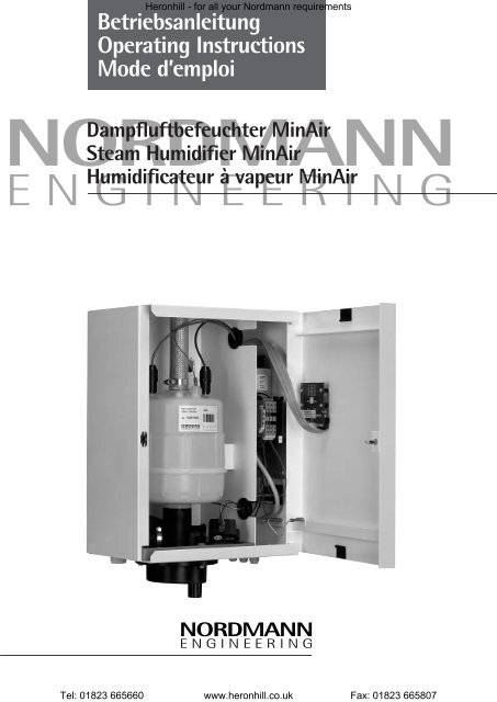
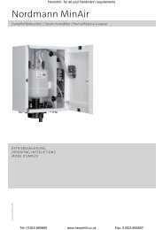
Heronhill - for all your Nordmann requirementsBetriebsanleitungOperating InstructionsMode d’emploiTel: 01823 665660 www.heronhill.co.uk Fax: 01823 665807NORDMANNDampfluftbefeuchter MinAirSteam Humidifier MinAirHumidificateur à vapeur MinAir<strong>ENGINEERING</strong>NORDMANN<strong>ENGINEERING</strong>
Heronhill - for all your Nordmann requirementsTel: 01823 665660 www.heronhill.co.uk Fax: 01823 665807
Heronhill - for all your Nordmann requirementsTel: 01823 665660 www.heronhill.co.uk Fax: 01823 665807InhaltDeutsch1. Sicherheitshinweise . . . . . . . . . . . . . . . . . . . . . . . . . . . . . . . . . . . . . . . . . . . . . . . . . . . . . . . . . . . . . . . . . . . . . . . . 42. Montage . . . . . . . . . . . . . . . . . . . . . . . . . . . . . . . . . . . . . . . . . . . . . . . . . . . . . . . . . . . . . . . . . . . . . . . . . . . . . . . . . 43. Wasseranschlüsse . . . . . . . . . . . . . . . . . . . . . . . . . . . . . . . . . . . . . . . . . . . . . . . . . . . . . . . . . . . . . . . . . . . . . . . . . . 54. Elektrische Anschlüsse . . . . . . . . . . . . . . . . . . . . . . . . . . . . . . . . . . . . . . . . . . . . . . . . . . . . . . . . . . . . . . . . . . . . . . 55. Inbetriebnahme . . . . . . . . . . . . . . . . . . . . . . . . . . . . . . . . . . . . . . . . . . . . . . . . . . . . . . . . . . . . . . . . . . . . . . . . . . . 66. Instandhaltung . . . . . . . . . . . . . . . . . . . . . . . . . . . . . . . . . . . . . . . . . . . . . . . . . . . . . . . . . . . . . . . . . . . . . . . . . . . . 87. Technische Daten . . . . . . . . . . . . . . . . . . . . . . . . . . . . . . . . . . . . . . . . . . . . . . . . . . . . . . . . . . . . . . . . . . . . . . . . . 19ContentEnglish1. Safety Instructions . . . . . . . . . . . . . . . . . . . . . . . . . . . . . . . . . . . . . . . . . . . . . . . . . . . . . . . . . . . . . . . . . . . . . . . . . 92. Installation . . . . . . . . . . . . . . . . . . . . . . . . . . . . . . . . . . . . . . . . . . . . . . . . . . . . . . . . . . . . . . . . . . . . . . . . . . . . . . . 93. Water connections . . . . . . . . . . . . . . . . . . . . . . . . . . . . . . . . . . . . . . . . . . . . . . . . . . . . . . . . . . . . . . . . . . . . . . . . 104. Electrical connections . . . . . . . . . . . . . . . . . . . . . . . . . . . . . . . . . . . . . . . . . . . . . . . . . . . . . . . . . . . . . . . . . . . . . 105. Putting into operation . . . . . . . . . . . . . . . . . . . . . . . . . . . . . . . . . . . . . . . . . . . . . . . . . . . . . . . . . . . . . . . . . . . . . 116. Maintenance . . . . . . . . . . . . . . . . . . . . . . . . . . . . . . . . . . . . . . . . . . . . . . . . . . . . . . . . . . . . . . . . . . . . . . . . . . . . . 137. Technical specifications . . . . . . . . . . . . . . . . . . . . . . . . . . . . . . . . . . . . . . . . . . . . . . . . . . . . . . . . . . . . . . . . . . . . 19Table des matièresFrançais1. Consignes de sécurité . . . . . . . . . . . . . . . . . . . . . . . . . . . . . . . . . . . . . . . . . . . . . . . . . . . . . . . . . . . . . . . . . . . . . . 142. Montage . . . . . . . . . . . . . . . . . . . . . . . . . . . . . . . . . . . . . . . . . . . . . . . . . . . . . . . . . . . . . . . . . . . . . . . . . . . . . . . . 143. Raccordement hydraulique . . . . . . . . . . . . . . . . . . . . . . . . . . . . . . . . . . . . . . . . . . . . . . . . . . . . . . . . . . . . . . . . . 154. Raccordement électrique . . . . . . . . . . . . . . . . . . . . . . . . . . . . . . . . . . . . . . . . . . . . . . . . . . . . . . . . . . . . . . . . . . . 155. Mise en service . . . . . . . . . . . . . . . . . . . . . . . . . . . . . . . . . . . . . . . . . . . . . . . . . . . . . . . . . . . . . . . . . . . . . . . . . . . 166. Entretien régulier . . . . . . . . . . . . . . . . . . . . . . . . . . . . . . . . . . . . . . . . . . . . . . . . . . . . . . . . . . . . . . . . . . . . . . . . . 187. Données techniques . . . . . . . . . . . . . . . . . . . . . . . . . . . . . . . . . . . . . . . . . . . . . . . . . . . . . . . . . . . . . . . . . . . . . . . 193
Heronhill - for all your Nordmann requirementsTel: 01823 665660 www.heronhill.co.uk Fax: 01823 665807DeutschVielen Dank dass Sie sich für den Dampfluftbefeuchter MinAir von NORDMANN entschieden haben.Bei Beachtung dieser Bedienungsanleitung gewährleistet das Gerät eine vollautomatische Funktion sowiesicheren und wartungsarmen Betrieb.1. Sicherheitshinweise!Bitte vor der Montage und der Inbetriebnahme die Bedienungsanleitung sorgfältig durchlesen und beachten!Wichtig:Die Bedienungsanleitung soll ständig am Einsatzort des Gerätes verfügbar sein.Sämtliche Montage- und Installations-Arbeiten dürfen nur von qualifiziertem Personal durchgeführt werden.Neben diesen Sicherheitshinweisen sind alle nationalen und lokalen Vorschriften zu beachten.Ohne schriftliche Genehmigung von NORDMANN dürfen am Dampfluftbefeuchter MinAir keine Umbautenvorgenommen werden.Es dürfen nur Original-Ersatzteile von NORDMANN verwendet werden.2.1 Montage des DampfluftbefeuchtersBeachten Sie bei der Montage des MinAir die erforderlichen Minimalabstände gemäss Fig. 3. Es empfiehlt sich,den Dampfluftbefeuchter möglichst nahe bei dem Dampfverteiler-Rohr oder der Dampfverteiler-Düse zu montieren.2.2 Montage der Dampfverteiler-DüseDie Montage der Dampfverteiler-Düse erfolgt gemäss Fig. 4. Der Dampfschlauch soll eine Länge von 1.5 Metern nichtüberschreiten.2.3 Montage des Dampfverteiler-RohresDer aus dem Dampfverteiler-Rohr ausströmende und sichtbare Dampfstrom vermischt sich erst nach einer gewissenDistanz mit der zu befeuchtenden Luft. Um Kondensatbildung im Kanal zu vermeiden ist deshalb ein bestimmterMindestabstand zu nachfolgenden Anlageteilen einzuhalten.Zur Erleichterung der Montage wird mit jedem Dampfverteiler-Rohr eine selbstklebende Montageschablonemitgeliefert. Die Dampfverteiler-Rohre von NORDMANN sind so konstruiert, dass das Rohr bei einer horizontalenMontage ein Gefälle von 3% aufweist und damit der Abfluss des Kondensats sichergestellt ist.2.4 Installation des DampfschlauchesDie Installation des Dampfschlauches erfolgt gemäss Fig. 5. Die Länge des Dampfschlauches ist so kurz wie möglich zuhalten. Die Dampfleitungen dürfen nicht absperrbar oder verschliessbar sein. Sie sind gegen äussere Einflüsse wie z.B.Abknicken, Deformieren, etc. zu schützen. Kondensatsäcke im Schlauch sind unbedingt zu vermeiden. Bei Bögen ist aufgrosse Radien zu achten.Zur Verbindung des Dampfschlauches mit dem Dampf-Zylinder und den Dampf-Verteilern sind die mitgeliefertenSchlauchschellen zu verwenden.Es empfiehlt sich eine Nachkontrolle der Dampfleitungen im Betriebszustand.InstallationsmaterialBei Installation der Dampfleitung mit einem Schlauch darf nur der Original-Dampfschlauch von NORDMANN eingesetztwerden. Für die Verwendung anderer Schläuche übernimmt NORDMANN im Schadensfall keine Haftung.Wenn die Installation der Dampfleitung in Cu-Rohr erfolgt, ist mindestens der gleiche Innendurchmesser wie beimDampfschlauch zu verwenden. Mit Cu-Rohr sind enge Biegeradien zu vermeiden, jeder Winkel erhöht den Innendruckder Dampfleitung.Lange Dampfleitungen mit vielen Winkeln, und/oder ein relativ hoher Druck im Lüftungskanal, bewirken unterUmständen ein kontinuierliches Überdrücken des Wassers aus dem Dampfzylinder, was einen Leistungsabfall desDampfluftbefeuchters zur Folge hat.42. Montage
Heronhill - for all your Nordmann requirementsTel: 01823 665660 www.heronhill.co.uk Fax: 01823 6658072.5 Installation des Kondensatschlauches (siehe Fig. 6)Der Kondensatschlauch ist möglichst vertikal zu führen und das Kondensat direkt in einen offenen Ablauftrichter oderunterhalb des Siphons zu leiten. Bei Montage des Dampfverteilers oberhalb des Dampfluftbefeuchters kann dasKondensat auch direkt zum Gerät geführt werden.3. Wasseranschlüsse3.1 WasserqualitätBefeuchter von Nordmann verwenden normales Leitungswasser für die Produktion von reinem Wasserdampf.Die elektrische Leitfähigkeit soll sich innerhalb der Spanne von min. 125 bis max. 1250 µS/cm bewegen.Der Härtebereich des Wassers wird nach den internationalen Einheit Millimol Calcium- und Magnesiumionen je LiterWasser (mmol/l) gemessen (früher Grad Deutsche Härte):weiches Wasser: bis 1.3 mmol/l bis 7° DHmittelhartes Wasser: 1.3 bis 2.5 mmol/l 8 bis 14° DHhartes Wasser: 2.5 bis 3.8 mmol/l 14 bis 21° DHsehr hartes Wasser: über 3.8 mmol/l über 21° DHandere internationale Einheiten:1° DH = 1.79° FH (Französische Härte)1° DH = 1.25° EH (Englische Härte)1° DH = 1.05° AH (Amerikanische Härte)1° DH = 10mg/l CaO1° DH = 17.9 mg/l Ca(HCO3)2Mit Elektroden-Dampfluftbefeuchtern von Nordmann kann weiches bis sehr hartes Wasser ohne Aufbereitungeingesetzt werden.3.2 Wasserzuführung und Wasserablauf (siehe Fig. 6)Beachten Sie bitte die lokalen Vorschriften betreffend Anschluss von Geräten an das Druck- und Abwassernetz.Betrieb ausschliesslich mit normalem Leitungswasser. Bei Betrieb mit behandeltem Wasser kontaktieren Sie bitte IhrenNORDMANN-Fachhändler!Bei einem Wasserdruck von 1–10 bar (0,1–1 MPa) ist der direkte Anschluss an das Leitungsnetz möglich. Bei einemLeitungsdruck über 10 bar (1 MPa) erfolgt der Anschluss über ein Druckreduzierventil, eingestellt auf 4–6 bar (0,4–0,6 MPa).In jedem Fall ist darauf zu achten, dass die Wasserleitungen vor dem Anschluss an den Befeuchter gut durchgespültwerden. Verwenden Sie ausschliesslich Kupferleitungen!Ein Feinfilter am Wassereinlass zu dem Befeuchter wird in jedem Fall empfohlen. So wird vermieden, dass sich das Siebdes Einlass-Ventils zu schnell mit Rückständen belegt.Achten Sie bei der Erstellung des Ablaufs auf die Möglichkeit für Unterhalt und Reinigung. Die Ablaufleitung ist mitgenügend Gefälle zur Kanalisation auszustatten (min. 5%).4. Elektrische Anschlüsse4.1 SicherheitshinweiseAlle Arbeiten, die die elektrische Installation betreffen, dürfen nur durch qualifiziertesFachpersonal ausgeführt werden.Für elektrische Arbeiten sind sämtliche Stromversorgungskreise zum Befeuchter spannungsfrei zu schalten!In der Installation ist eine Vorrichtung einzubauen, die das Gerät allpolig - mit einer Kontaktöffnungsweite vonmindestens 3 mm – vom Netz trennt.Befeuchter von NORDMANN sind für den Anschluss an Schutzleiter vorgesehen und gehören zur Kategorie fürelektrische Geräte "Schutz-Klasse I".Beachten Sie bitte die lokalen Vorschriften betreffend der Ausführung von elektrischen Installationen.Die Anschlussdaten sind dem Elektroschema zu entnehmen. Das entsprechende Schema wird jedem Gerät beigelegt.5
Tel: 01823 665660 www.heronhill.co.uk Fax: 01823 6658075. InbetriebnahmeHeronhill - for all your Nordmann requirements5.1 Funktion des DampfluftbefeuchtersDampfluftbefeuchter von NORDMANN verwenden normales Leitungswasser für die Produktion von Wasserdampf.Das Wasser wird in einem Dampfzylinder mit Elektroden-Heizung mittels elektrischer Energie direkt in Wasserdampfumgewandelt. Das Wasser spielt dabei die Rolle des elektrischen Widerstands. Die Verdampfung erfolgt beiatmosphärischem Druck (drucklos).Die Steuerelektronik mit Mikro-Controller regelt den Verdampfungsprozess nach dem bewährten von NORDMANNentwickelten Prinzip. Dieses ermöglicht reaktionsschnelle Leistungsänderungen. Vollautomatisch erfolgt eine optimaleAnpassung an die jeweilige Qualität des verwendeten Wassers. Durch diese Selbsteinstellung der optimalen Wasserkonzentrationim Dampfzylinder kann eine Änderung der Dampfleistung durch kleinste Variationen des Wasserpegelserreicht werden. Sollwert Änderungen werden deshalb besonders schnell und präzise verarbeitet. Mit dem grösstmöglichenWirkungsgrad sorgt die Steuerung für einen optimalen Ablass, d.h. den Prozess der Dekonzentration desWassers im Zylinder. Die angewendete Technik der Fuzzy Logic ermöglicht eine Verbesserung der Regelaufgaben.Durch die adaptive Steuerungstechnik wird die Leitfähigkeit/Mineralkonzentration im Dampfzylinder geregelt und einoptimaler Betrieb bei gleichzeitiger Maximierung der Betriebszuverlässigkeit erreicht.Ferner sind die im Normalbetrieb vorkommenden Leistungsschwankungen durch die automatischen Funktionen,Wassereinlass und -ablass, in einem optimalen Rahmen gehalten.Der integrierte Regler des MinAir arbeitet als P-Regler mit fest eingestelltem Proportionalband. Die Vorgabe desSollwerts erfolgt über die Eingabetasten des MinAir. Die erzeugte Dampfmenge wird von der Steuerung optimalausgeregelt.5.2 Bedienung und Einstellung des MinAirDas zweistellige LED-Anzeigemodul zeigt im Normalbetrieb die über den angeschlossenen Feuchtefühler gemessenerelative Luftfeuchtigkeit an. Zusätzlich werden System- und Wartungs-Meldungen angezeigt.Standardanzeige Anzeige der relativen Luftfeuchte, die vom angeschlossenen Feuchtefühler gemessen wird.Bei Dampfproduktion, ist der rechte Dezimalpunkt aktiv.Taste T1 (Pfeil aufwärts) Mit dieser Taste kann nach einmaligem Betätigen der eingestellte Sollwert auf derLED-Anzeige abgerufen werden.Nach dem zweiten Betätigen erscheint der Status des FüllstandsensorsL 0 ➩ Sensor nicht bedecktL 1 ➩ Sensor bedeckt, d.h. maximaler Füllstand im Dampfzylinder erreichtNach 10 Sekunden schaltet die Anzeige auf die Standardanzeige zurück.Wartungsmeldungen (siehe 5.4) lassen sich durch einmaliges Betätigen von T1 zurücksetzen.Taste T2 (Pfeil abwärts) Durch Betätigen dieser Taste für eine Dauer von mindestens 2 Sekunden wird dieZylinderentleerung aktiviert. Die Dampfproduktion wird unterbrochen, das Ablassventil öffnetund die LED-Anzeige blinkt mit der Anzeige eines Doppelbalkens. Das Ablassventil schliesstnach einer Ablasszeit von 30 Minuten automatisch.Die Zylinderentleerung wird mit erneuter Betätigung von T2 für zwei Sekunden wiederabgebrochen.Zur Einstellung des Sollwertes relative Feuchte sind beide Tasten gleichzeitig für mindestens vier Sekunden zu betätigen.Die Anzeige schaltet auf den blinkenden Sollwert um. Der Sollwert kann jetzt mit den beiden Tasten erhöht oderverringert werden. Nach 10 Sekunden ohne Tastenbetätigung wird der neue Sollwert übernommen und die Anzeigeschaltet auf die Standardanzeige zurück.5.3 InbetriebnahmeNach dem fachgerechten Anschluss von Dampfschlauch, Wasserzufuhr und Wasserablass sowie der elektrischenZuleitungen, wird der Befeuchter MinAir mit dem schwarzen Netzschalter eingeschaltet. Durch einen Druck auf dieTaste T1 wird der eingestellte Sollwert angezeigt. Der gewünschte Sollwert kann nach Bedarf eingestellt werden(siehe Punkt 5.2).Sobald der integrierte Feuchteregler Befeuchtung anfordert, leuchtet der rechte Dezimalpunkt der LED-Anzeige aufund der Schütz zieht an. Nach kurzer Zeit wird Wasser in den Dampfzylinder gefüllt und der vollautomatische Betriebbeginnt. Voraussetzung für die automatische Operation ist natürlich eine fachgerechte Montage sowie ein geöffnetesAbsperrventil in der Wasserzuführung.Nach Erwärmung des Wassers im Dampfzylinder beginnt die Dampfproduktion.6
Heronhill - for all your Nordmann requirementsTel: 01823 665660 www.heronhill.co.uk Fax: 01823 665807Während der Anlaufphase, oder nach dem Einbau eines neuen Ersatz-Zylinders, kann der Maximalfüllstand imDampfzylinder erreicht werden und der Füllstandssensor ansprechen. Das Erreichen des Maximalfüllstands bewirktein momentanes Schliessen des Einlassventils. Dies ist ein normaler Vorgang während der Konzentrationsphase desDampfzylinders. Diese Konzentrationsphase kann unterschiedliche Zeitspannen aufweisen und dauert so langebis der Zylinder seine Nennleistung erreicht hat. Durch zweimaliges Drücken von T1 kann geprüft werden, ob derMaximalfüllstand erreicht ist (siehe Punkt 5.2).5.4 Wartungs- oder System-MeldungenDie Steuerelektronik mit Mikro Controller überwacht die Gerätefunktionen des MinAir kontinuierlich. EventuelleAbweichungen vom Betriebszustand (U-Meldungen) werden auf dem Display angezeigt.Meldung Die Meldung U1 ist eine Wartungsmeldung.‘’U1’’ Der Dampfzylinder kann die geforderte Nennleistung nicht mehr erbringen und soll gereinigt oder eventuellausgewechselt werden. Siehe dazu auch Kapitel 6.3 Die Meldung U1 ist eine reine Service-Meldung, es erfolgt keineautomatische Abschaltung des Gerätes. Der Befeuchter bleibt mit reduzierter Leistung in Betrieb.Meldung Meldung ‘’Überstrom’’‘’U2’’ Bei einem betriebsmässig vorhandenen Überstrom (140 % des Nennstroms) schaltet der Befeuchter aus Sicherheitsgründendie Dampfproduktion aus. Die Wiederinbetriebnahme nach Störungsbeseitigung erfolgt durch Betätigen derTaste T1 (Pfeil aufwärts).Meldung Der Befeuchter versucht den Zylinder zu füllen, ohne dass die angeforderte Dampfleistung erreicht wird.‘’U3’’ Mögliche Ursachen sind eine unterbrochene Wasserzufuhr, ein defektes Leistungsrelais oder Einlassventil oderÜberdruck in der Dampfleitung z.B. wegen geknicktem Dampfschlauch. Nach 30 Minuten erfolgt die automatischeAbschaltung des Befeuchters. Die Wiederinbetriebnahme nach Störungsbeseitigung erfolgt durch Betätigung derTaste T1 (Pfeil aufwärts)Meldung Meldung ‘’Mikro Controller Steuerelektronik nicht kodiert.’’‘’U4’’ Diese Meldung erscheint wenn eine Ersatz-Steuerelektronik unkodiert in das Gerät eingesetzt wird. Der Betrieb desBefeuchters wird nicht freigegeben. Die Meldung erlischt, wenn die Steuerelektronik gemäss dem im Geräteingeklebten Kodierkleber kodiert wird.5.5 SicherheitsfunktionenBefeuchter von NORDMANN sind gegen Trockenlauf geschützt, d.h. der Stromfluss wird automatisch unterbrochen,wenn die Elektroden im Dampfzylinder aus dem Wasser ragen.Sollte die Stromaufnahme den Nominalwert wesentlich übersteigen (+ 25%), wird automatisch das Ablassventilgeöffnet. Da die Elektroden dann eine geringere Eintauchtiefe im Wasser aufweisen, fällt die Stromaufnahmeauf den Nominalwert zurück.Sollte sich die Stromaufnahme nach mehreren Ablassoperationen immer noch über 140% des Nennstroms befinden, soschaltet der Befeuchter nach kurzer Zeit automatisch ab und die System-Meldung ‘’U2’’ erfolgt auf der LED-Anzeige.5.6 FernmeldungEin serienmässiger, potentialfreier Relais-Ausgang ermöglicht eine Fernanzeige der System-Meldungen U1, U2 und U3.7
Heronhill - for all your Nordmann requirementsTel: 01823 665660 www.heronhill.co.uk Fax: 01823 6658076. InstandhaltungRegelmässige Instandhaltung hält die Funktionstüchtigkeit des Gerätes aufrecht.Diese Arbeiten sind nur durch Fachpersonal durchzuführen.6.1. Regelmässige Kontrollen• Dampfzylinder überprüfen:Sind Kalkrückstände im Zylinder?➩Ablass-Sieb entfernen und kräftig mit Leitungswasser durchspülen (ohne chemische Zusätze).Vor der Reinigung das Ablass-Sieb aus dem Zylinderfuss ziehen und nach der Reinigung unbedingtwieder einsetzen.Sind die Elektroden abgenutzt?➩ Dampfzylinder ersetzen.•Dampfschläuche, Kondensatschläuche und Wasserschläuche (auch im Befeuchter) überprüfen:Ist die Installation noch in Ordnung?Sind die Schlauchschellen noch fest angezogen?• Einlass- und Ablassventil überprüfen:Bei starken Abnutzungserscheinungen oder Kalkablagerungen das Ventil ersetzen.Ablassbecher kontrollieren und wenn nötig entfernen und reinigen.6.2 Behebung von StörungenDer Befeuchter produziert nicht genügend oder keinen Dampf. Folgende Ursachen sind denkbar:• der Feuchteregler fordert keine Dampfproduktion an• es befindet sich kein Wasser im Zylinder weil die Wasserzufuhr unterbrochen ist• der Filter oder die Düse im Einlassventil ist verstopft / defekt• der Dampfzylinder ist verbraucht und muss ersetzt werden• das Leistungsrelais ist defekt• der Feuchtefühler ist nicht richtig angeschlossen6.3 Austausch des ZylindersDie Lebensdauer eines Dampfzylinders ist abhängig von der Betriebszeit sowie der Härte des Wassers.Der Zylinder sollte ersetzt werden wenn die System-Meldung U1 angezeigt wird. Der Befeuchter kann unterUmständen noch einige Zeit bis zum Austausch weiterbetrieben werden.Es wird wie folgt vorgegangen:a) Zylinderentleerung durch Drücken von T2 für mindestens zwei Sekunden aktivieren.Der Dampfzylinder wird vollständig entleert. Dampfzylinder abkühlen lassen.Für die folgenden Arbeitsschritte ist das Gerät vom Stromnetz zu trennen!b) Schlauchschelle am Zylinderkopf lösen und den Dampfschlauch und die Elektrodenstecker abziehen.Anschliessend den Zylinder nach oben schieben und herausnehmen.c) Dichtung (O-Ring) in der Zylinderaufnahme kontrollieren und eventuell austauschen.d) Einsetzen des gereinigten oder neuen Dampfzylinders in umgekehrter Reihenfolge.Der Neustart des Befeuchters erfolgt gemäss dem Kapitel 5 "Inbetriebnahme".6.4 Ausserbetriebnahme des BefeuchtersFür den Fall, dass der Befeuchter während einer längeren Zeit ausser Betrieb genommen wird (z.B. im Sommer,Ausserbetriebnahme der Klimaanlage etc.), ist der Dampfzylinder zu entleeren.8
Heronhill - for all your Nordmann requirementsTel: 01823 665660 www.heronhill.co.uk Fax: 01823 665807EnglishThank you for purchasing the MinAir steam humidifier from NORDMANN. Provided these operating instructions are observed, thisunit will ensure fully automatic operation and reliable, low maintenance service.1. Safety Instructions!Please carefully read and observe the operating instructions before installation and use!Important:The operating instructions should always be readily available and kept in the immediate vicinity of the humidifier.All installation work must be carried out by qualified personnel.Apart from these safety instructions, national and local regulations must be observed.Without NORDMANN’s written approval, no alterations may be made to the MinAir humidifier itself, its componentsor accessories.The use of non-original spare parts may lead to our refusal to accept responsibility for any damage arising therefrom.2. Installation2.1 Fitting the humidifierWhen fitting the MinAir please note the necessary minimum clearances given in Fig. 3. It is advisable to install thesteam humidifier as close as possible to the steam distribution pipe or the steam distribution nozzle.2.2 Fitting the steam-distribution nozzleAssemble the steam nozzle in accordance with Fig. 4. The steam hose should be no longer than 1.5m.2.3 Fitting the steam-distribution pipeThe visible jet of steam issuing from the steam-distribution pipe dissipates in the air over after a certain distance.In order to prevent condensation on other parts in the duct, ensure this minimum distance is maintained.For ease of the assembly, an adhesive assembly template is supplied with each steam distribution pipe. NORDMANN`ssteam-distribution pipes are designed so that, when fitted straight, an automatic decline of 3%, allows any condensateto drain properly.2.4 Laying the steam hoseInstall the steam hose in accordance with Fig. 5. The length of the steam hose should be kept as short as possible.The steam pipes may not be lock offable or lockable. It should be protected from outside interference (e.g. deformities,kinking etc.). and not fixed to any structure. Condensation pockets in the steam hose must be avoided under anycircumstances. Any curves must have as large as possible radii.Use the hose clamps provided to connect the steam hose to the steam cylinder and steam distribution pipe.A check of the steam pipes in the operating condition is recommended.Installation materialIf a hose is used for the steam line, it must be the original one supplied by NORDMANN. If other hoses are utilised,NORDMANN cannot be held responsible for any damage that may occur.If the steam line installed is of copper tube, it must be at least the same diameter as the steam hose. With copper pipessmall radii should be avoided wherever possible. Every bend causes a rise of the internal pressure of the steam line.Under certain circumstances where long steam lines with several bends are used and a relatively high internal ductpressure exists, water may be continuously forced out of the steam cylinder. This will impair the performance of thehumidifier.9
Heronhill - for all your Nordmann requirementsTel: 01823 665660 www.heronhill.co.uk Fax: 01823 6658072.5 Laying the condensate hose (see Fig. 6)The condensate hose has to be laid as near to the vertical as possible fed directly into an open funnel or below thesiphon. When fitting the steam distribution pipe above the humidifier, the condensate can be fed directly to the unit byplacing the end of the hose in the filling cup.3. Water connections3.1 Water qualityNORDMANN humidifiers use ordinary tap water for the production of pure steam. The electrical conductivity should bebetween 125 and 1250 microsiemens per cm. The hardness of water is measured in accordance with the internationalunit millimol, calcium and magnesium ions per litre (mmol/l), previously known as degree of German hardness (DH):Soft water:Fairly hard water:Hard water:Very hard water:up to 1.3 mmol/l; up to 7° DH1.3 to 2.5 mmol/l; 8 to 14° DH2.5 to 3.8 mmol/l; 14 to 21° DHmore than 3.8 mmol/l; more than 21 ° DHOther international units:1° DH = 1.78° FH (French hardness)1° DH = 1.25° EH (English hardness)1° DH = 1.05° AH (American hardness)1° DH = 10mg/l CaO1° DH = 17.9 mg/l Ca(HCO3)2NORDMANN’s electrode steam humidifiers use water ranging from soft to very hard, without the need for priortreatment.3.2 Water intake and drainage (see Fig. 6)National and local regulations must be observed.Please observe local regulations concerning the connection of appliances to the pressure and drainage water systems.The humidifiers are designed to operate on ordinary tap water only. If you intend using treated water, consult yourNORDMANN representative.Where the water pressure is between 1 and 10 bar (0,1 to 1 MPa), the unit can be connected directly to the watersupply. If it is over 10 bar (1MPa) connection must be via a pressure reduction valve, set to 4–6 bar (0,4–0,6 MPa).Water feed pipes must be thoroughly flushed before connecting them to the humidifier. Copper piping only should be used.It is recommended to use a fine filter in the water intake line to the humidifier. This prevents the rapid build –up ofsediments in the filter of the inlet valve.Please ensure the drainage facility allows the humidifier to perform correctly and provides clear access for cleaning andmaintenance. The drainage pipe should have a decline to the drainage system of at least 5%.4. Electrical connections4.1 Safety instructionsOnly qualified personnel must carry out the electrical installation.Before performing any electrical work, all power to the humidifier must be disconnected!The installation must be fitted with a device that disconnects the unit (with contact opening of at least 3mm) on allphases from the mains power supply.NORDMANN humidifiers are designed to be connected to the earth lead and are categorised as belonging to Class 1Protection for electrical equipment.Please observe local regulations concerning the execution of electrical installations.The connection details are provided in the wiring diagram supplied with each unit.10
Tel: 01823 665660 www.heronhill.co.uk Fax: 01823 6658075. Putting into operation5.1 How the humidifier worksNORDMANN humidifiers use ordinary tap water to produce steam. The water is converted directly into steam in thesteam cylinder by electrode heating using electrical energy. In this way, the water acts as the electrical resistance.Vaporisation occurs at atmospheric pressure (non-pressurised).The electronic control system, with its micro controller, regulates the vaporisation process in accordance with thereliable principle developed by NORDMANN. This principle allows rapid output changes. The humidifier adapts itselfautomatically to the quality of the water used.Due to this ability to set the optimum water concentration in the steam cylinder, the smallest adjustments to thewater level can effect a change in the steam output, allowing the unit to react quickly and accurately to any setpoint change.The control system’s high degree of efficiency ensures optimal drainage, i.e. the process of water deconcentration inthe cylinder.The use of fuzzy logic technology improves controllability. The adaptive control technique regulates theconductivity / mineral concentration in the steam cylinder achieving ideal operating conditions and maximisingoperational reliability. In addition, the output fluctuations, which occur during normal operation, are kept to aminimum by the automatic water-intake and drainage functions.The integrated humidity controller of the MinAir works as a P-Controller with a fixed proportional band. The defaultof the desired value is made by the input keys of the MinAir. The electronic controller optimally controls the steamproduced.5.2 Handling and setting of the MinAirThe two digits LED display module indicates the relative humidity in the air measured by the humidity sensor in thenormal operation. Additional system and maintenance messages are also indicated.Standard Display:Button T1 (arrow upwards):Heronhill - for all your Nordmann requirementsDisplay of the relative humidity (RH), which will be measured by the connectedhumidity sensor.A decimal point on the right hand side on the LED display will light up as long thehumidifier is producing steam.After pressing this button once, the nominal set point will be shown on the LED display.After pressing the button a second time, the status of the maximum level sensor will beshown on the LED display.L 0 ➩L 1 ➩Max. Level sensor is not activatedMax. level sensor is activated, e.g. maximum possible water levelhas been reached in the steam cylinder.After 10 seconds the LED switches back to the standard display.By pressing button T1 once, servicing messages (see chapter 5.4) can be reset.Button T2 (arrow downwards): By pressing this button for at least 2 seconds, the manual cylinder drainage will beactivated. The steam production will be interrupted and the drainage valve will open.During this operation, two bars will blink on the LED display. After 30 seconds thedrainage valve will automatically close. The manual drainage function can be stoppedafter depressing the button T2 for two seconds.To set the nominal value of the required relative humidity, both buttons have to be pressed at the same time for atleast 4 seconds. The display will start blinking and show the nominal value. The nominal value can be changed using theup (T1) and down (T2) buttons. If the buttons are not pressed for at least 10 seconds the new nominal Value will beaccepted and the display switches back to the standard display.5.3 Putting the humidifier into operationAfter the steam hose, water feed pipe, drainage pipes and electrical cables have all been correctly and professionallyconnected, the MinAir humidifier can be switched on using the black power switch. By pressing the T1 button, the setnominal value will be displayed. The desired nominal value can be set according to requirements (see chapter 5.2). Assoon as the integrated humidity controller asks for humidity, the decimal point of the Display will light up, the contactorwill be activated and after a short time water is fed into the steam cylinder and full automatic operation commences.The humidifier will only operate automatically if correctly installed and the shut-off valve in the water feed pipe is open.Steam production will commence when the water in the cylinder has been fully heated.11
Heronhill - for all your Nordmann requirementsTel: 01823 665660 www.heronhill.co.uk Fax: 01823 665807During the start-up phase, or after a new replacement cylinder has been fitted, the maximum water level can beattained. When the maximum water level has been reached, the inlet valve closes briefly; this is a normal occurrenceduring the steam cylinder concentration phase. The length of this phase can vary; it lasts until the cylinder has reachedthe nominal rating. It can be examined by pressing button T1 twice at any time (see chapter 5.2)5.4 Servicing and system messagesThe electronic control unit with microprocessor continuously monitors the operation of the MinAir. Eventuallydeviations from the operating condition (U-codes) will be shown on the display.Code‘’U1’’Code‘’U2’’Code‘’U3’’Code‘’U4’’Code "U1" is a servicing signal.The steam cylinder can no longer attain the nominal output and needs, therefore, to be cleaned or perhaps replaced(refer to chapter 6.3). Code "U1" is a purely servicing code. The unit does not switch off automatically and thehumidifier continues to function at a reduced output. Acknowledgment is affected by the reset procedure.Message ‘’excess current’’Whenever there is excess current (140% of the nominal value) during normal operations, the humidifier switches itssteam production off automatically for safety reasons. After the fault has been rectified, the humidifier is put back intooperation by pressing T1.The humidifier tries to fill the steam cylinder, without reaching the required steam capacity.Possible causes are interrupted water supply, a defective contactor relay or inlet valve, or overpressure in the steam linefor eg. due to kinked steam hose. The humidifier switches itself off automatically after 30 minutes. After the fault hasbeen rectified, the humidifier is put back into operation by pressing T1 (arrow upwards).Micro controller displays no code.This signal appears if a replacement electronic control unit has been fitted to the humidifier without being code, whichprevents the humidifier from operating. The signal disappears as soon as the electronic controls unit has been codedaccording to the settings shown on the coding sticker inside the unit.5.5 Safety functionsNORDMANN humidifiers are protected against running dry, i.e. the power is cut off automatically as soon as theelectrodes in the steam cylinder protrude above the water level.If current consumption becomes excessive (25% above the nominal level), the outlet valve is opened automatically.Because the electrodes are then in contact with less water, current consumption falls back to the nominal value.If current fails to fall below 140% of the nominal level, even after several drainage operations, the humidifier turnsitself off automatically and the failure message "U2" appears on the LED display.5.6 Remote indicationA standard, potential-free relay output enables the alarm messages U1, U2 and U3 to be remotely displayed.12
Heronhill - for all your Nordmann requirementsTel: 01823 665660 www.heronhill.co.uk Fax: 01823 6658076. Maintenance!Regular servicing helps to maintain the operation of the humidifier.Only qualified personnel must carry out following work.6.1. Regular Checks•Inspect the steam cylinder:Are there any deposits in the steam cylinder?➩Remove the drainage strainer and flush the cylinder thoroughly with tap water (without usingchemical substances). Replace the strainer after cleaning.Are the electrodes worn?➩ Replace the steam cylinder.• Inspect the steam, condensate and water hoses (also inside the humidifier):Is the installation still correct?Are the clamps still fastening tight?• Inspect the intake and drainage valves:If worn, or covered in scale deposits, the valves must be replaced.Check the drainage cup. If necessary clean or replace.6.2 Rectifying faultsThe humidifier produces insufficient or no steam. Following causes are possible:• The humidity controller is not demanding any steam production• There is no water in the steam cylinder because the water supply has been interrupted (e.g. stop cock is closed etc.)• The filter or the nozzle in the inlet valve is blocked or damaged• The steam cylinder is worn out and needs to be replaced• The power relay is defective• The humidity sensor is not connected properly.6.3 Replacing the cylinderThe serviceable life of the steam cylinder is dependent on the hardness of the tap water used and the unit’s actual operating hours.The cylinder should be replaced when the system message U1 appears on the LED display. Under certain circumstancesthe cylinder can still be used before it has to be replaced.It has to be proceeded as follows:a) Empty the cylinder by pressing button T2 for at least two seconds. Let the cylinder cool down.For the following work procedures the equipment must be separated from power supply!b) Loosen the clamp on the cylinder head and then remove the steam hose and the electrode plugs from the cylinder.Push up and remove.c) Check the Seal (O-ring) in the cylinder admission and replace if necessary.d) To fit the new unit reverse the above procedure.Re-start in accordance with section 5.36.4 Taking the humidifier out of operationIf the humidifier is out of operation for a long period of time e.g. in summer or when the air conditioning system is notoperating, the steam cylinder must be emptied.13
Heronhill - for all your Nordmann requirementsTel: 01823 665660 www.heronhill.co.uk Fax: 01823 665807FrançaisMerci d’avoir choisi l’humidificateur d’air MinAir de NORDMANN. Respecter les consignes de ce manuel de mise enservice vous garantira un fonctionnement automatique et une maintenance minimale de votre appareil.1. Consignes de sécurité!Avant toute utilisation ou mise en service il est impératif de lire attentivement ce manuel de mise en service !Important:Le manuel de mise en service doit en permanence être disponible à proximité de l’appareil.Le montage ainsi que l’installation de l’appareil ne doivent être réalisés que par du personnel qualifié.En parallèle à ces consignes de sécurité, toutes les réglementations locales ou nationales doivent êtrescrupuleusement respectées.Sans autorisation écrite de NORDMANN il est interdit de modifier l’humidificateur d’air MinAir.Dans tous les cas n’utiliser que les pièces de rechange originales NORDMANN.2. Montage2.1 Montage de l’humidificateurLors du montage du MinAir, il est impératif de respecter les distances minimales conformément à la Fig. 3.Il est conseillé de monter l’humidificateur aussi près que possible de la rampe ou de la buse de distribution de vapeur.2.2 Montage de la buse de distribution de vapeurLe montage de la buse de distribution de vapeur doit être réalisé conformément à la Fig. 4. La longueur maximale dutuyau de vapeur ne doit pas dépasser 1,5m.2.3 Montage des rampes de distribution de vapeurLe jet de vapeur visible qui s’échappe de la rampe de distribution vapeur ne se mélange à l’air qu’après une certainedistance. Afin d’éviter la formation de condensation dans le canal il est impératif de respecter une distance minimaleentre la rampe de distribution et les éléments montés en aval de celle-ci.Les rampes de distribution de vapeur peuvent être installées verticalement ou horizontalement. Toutefois, il estimpératif de s’assurer que les ouvertures de sortie vapeur soient toujours dirigées verticalement par rapport au fluxd’air. Dans le cas d’une implantation horizontale, les ouvertures de sortie vapeur doivent être dirigées vers le haut.Chaque rampe de distribution est livrée avec un gabarit de fixation pour faciliter le montage de la rampe dans la gainede ventilation.Les rampes de distribution NORDMANN sont conçues en ayant une inclinaison de 3% garantissant automatiquement leretour des condensats.2.4 Pose du tuyau vapeurLa pose du tuyau vapeur doit être réalisée conformément à la Fig. 5. La longueur du tuyau vapeur doit être aussi courteque possible. Le tuyau vapeur ne doit en aucun cas pouvoir se bloquer ou s’obstruer. En outre il doit être protégé contreles influences externes telles que des plis, déformations etc…. Il est impératif d’éviter toute poche de condensat dans letuyau de vapeur. En cas de coude, le rayon de courbure de celui-ci doit être aussi grand que possible.Le raccordement du tuyau vapeur au cylindre et à la rampe de distribution s’effectue à l’aide des colliers livrés avecl’appareil.Il est recommandé de recontrôler la pose des tuyaux vapeur après la mise en service de l’humidificateur et après quelquesheures de fonctionnement (lorsque le tuyau est chaud).Matériel d’installation:Il est impératif d’utiliser le tuyau vapeur original fourni par NORDMANN.NORDMANN décline toute responsabilité en cas de dommage si un autre tuyau vapeur est utilisé.Si le raccordement à la rampe de distribution se fait au moyen d’un tube cuivre, il faut éviter les coudes à petitsrayons. Le tube cuivre doit posséder au moins le même diamètre interne que le tuyau vapeur. Chaque coude augmenteconsidérablement la pression interne du tuyau.Une longueur de tuyau importante ainsi qu’ un grand nombre de coudes et une pression importante dans la gaineprovoquent une poussée sur l’eau contenue dans le cylindre à vapeur ce qui entraîne une perte de puissance de l’appareil.14
Heronhill - for all your Nordmann requirementsTel: 01823 665660 www.heronhill.co.uk Fax: 01823 6658072.5 Pose du tuyau condensat (cf. Fig. 6)Il est conseillé d’installer le tuyau condensat dans le sens vertical autant que possible et de le faire déboucher directementen-dessous du siphon d’évacuation. Si la rampe de distribution vapeur est située au-dessus de l’humidificateur, onpeut également faire écouler les condensats dans le godet de remplissage de l’appareil.3. Raccordement hydraulique3.1 Qualité de l’eauLes humidificateurs NORDMANN utilisent de l’eau de ville pour la production de vapeur pure. La conductivité électriquede l’eau doit se situer entre 125 et 1250 µS/cm.La dureté de l’eau est mesurée conformément à l’unité internationale : millimole d’ions calcium et magnesium par litre(mmol/l), jusqu’à présent en degré TH ou dureté allemande (DH):Eau douce:jusqu’à 1.3 mmol/l ; jusqu’à 7° DHEau moyennement dure: 1.3 à 2.5 mmol/l ; 8° à 14° DHEau dure: 2.5 à 3.8 mmol/l ; 14° à 21° DHEau très dure: sup.à 3.8 mmol/l ; sup. à 21° DHAutres unités internationales : 1°DH = 1.78° Dureté française1°DH = 1.25° Dureté anglaise1°DH = 1.05° Dureté américaine1°DH = 10mg/l CaO1°DH = 17.9 mg/l Ca(HCO3)2Les humidificateurs à électrodes NORDMANN vous permettent d’utiliser de l’eau douce jusqu’à très dure, sans recourir àun système de traitement d’eau.3.2 Alimentation en eau et évacuation (cf. Fig. 6)Veuillez respecter les réglementations locales relatives au raccordement d’un appareil au réseau de distribution etd’évacuation d’eau.Utiliser exclusivement de l’eau de ville. En cas d’utilisation d’eau traitée, consulter votre distributeur NORDMANN!Le raccordement direct au réseau d’eau est possible entre 1 et 10 bar (0,1 à 1 MPa) de pression. Si la pression du réseauest supérieure à 10 bar (1 MPa), le raccordement se fera via une soupape de réduction de pression réglée entre 4 et6 bar (0,4–0,6 MPa).Dans tous les cas il faut veiller à bien rincer la conduite d’eau alimentant l’humidificateur avant la première mise enservice. Nous conseillons d’utiliser uniquement des conduites en cuivre!Il est fortement recommandé d’installer un filtre fin sur l’arrivée d’eau de l’humidificateur afin de ne pas boucher lavanne d’alimentation.Tenez compte, lors de l’installation du tuyau d’évacuation, du nettoyage et de la maintenance à effectuer régulièrementsur l’humidificateur. Le tuyau d’évacuation doit avoir une pente minimale de 5% .4. Raccordement électrique4.1 Consignes de sécuritéToutes les interventions concernant l’installation électrique sont à effectuer uniquement par dupersonnel qualifié.Pour tous travaux électriques, veiller à ce que les alimentations électriques de l’humidificateur soit coupée!L’installation doit être munie d’un sectionneur pour chaque phase garantissant une ouverture des contacts d’au moins 3mm.Les humidificateurs NORDMANN sont prévus pour un raccordement à la terre et font partie de la catégorie d’appareilsélectriques de «classe de protection 1».Veuillez respecter les réglementations locales relatives aux installations électriques.Les données de raccordements sont indiquées sur le schéma électrique correspondant à chaque appareil. Un schémaélectrique est livré avec chaque appareil.15
Heronhill - for all your Nordmann requirementsTel: 01823 665660 www.heronhill.co.uk Fax: 01823 6658075. Mise en service5.1 Comment fonctionne l’humidificateurLes humidificateurs NORDMANN utilisent de l’eau de ville standard pour produire de la vapeur d’eau. L’eau esttransformée directement en vapeur dans un cylindre par des électrodes utilisant de l’énergie électrique. L’eau secomporte dans ce cas comme une résistance électrique. La vaporisation a lieu à pression atmosphérique (pas desurpression).Le système de contrôle électronique, avec micro-contrôleur intégré règle le processus de vaporisation. L’efficacité de ceprincipe de contrôle, développé par NORDMANN, permet des variations rapides du débit de vapeur. L’humidificateurs’adapte automatiquement à la qualité d’eau utilisée. Le contrôle optimal de la concentration de l’eau permet uneréaction rapide de l’appareil. Le plus petit changement de niveau d’eau dans le cylindre modifiera instantanément ledébit vapeur de l’humidificateur . Un changement de valeur du point de consigne sera par conséquent très rapidementréajusté. Le contrôle de la déconcentration de l’eau se fait de la manière la plus efficace qui soit en vidangeantautomatiquement et régulièrement une partie de l’eau du cylindre.L’utilisation de la logique floue améliore sensiblement le fonctionnement de l’humidificateur. En effet, la concentrationen minéraux et la conductivité électrique de l’eau sont optimisées ce qui vous assure un fonctionnement fiable et unedurée de vie maximale de votre appareil.De plus, les fluctuations de débit qui ont lieu durant un fonctionnement normal restent minimales grâce àl’alimentation d’eau automatique et aux fonctions de vidange.Le contrôleur intégré du MinAir fonctionne en régulateur proportionnel avec bande proportionnelle fixe. La valeurde consigne est réglable grâce aux boutons poussoirs de l’humidificateur et la quantité de vapeur produite est doncautomatiquement compensée.5.2 Fonctionnement et réglage du MinAirL’affichage digital à 2 digits. permet d’afficher en fonctionnement normal l’humidité relative mesurée par le capteur etles informations concernant le système et sa maintenance.Affichage standardAffiche l’humidité relative mesurée par le capteur.Lorsque l’appareil produit de la vapeur le point décimal de droite est actif.Touche T1 (Flèche vers le haut) En appuyant une fois sur cette touche, on interroge la valeur de consigne actuelleEn appuyant une deuxième fois sur cette touche on affiche l’état du détecteur deniveau hautL 0 ➩ détecteur inactifL 1 ➩ détecteur actif = niveau max. dans le cylindre est atteintAprès 10 secondes, l’afficheur revient en mode d’affichage standard.Les messages d’entretien (cf. § 5.4) se réinitialisent en appuyant une fois sur la touche T1.Touche T2 (Flèche vers le bas)En restant appuyé sur la touche T2 pendant plus de 2 secondes on active la fonctionvidange manuelle du cylindre . La production de vapeur est interrompue, la vanne devidange s’ouvre et deux barres verticales clignotent sur l’afficheur. En pressant une seconde fois sur la touche T2 plus de 2 secondes, l’électrovanne se referme. Si on oubliede refermer l’électrovanne de vidange, elle se fermera automatiquement au bout de30 minutes.Pour modifier la valeur de consigne il faut appuyer simultanément sur les touches T1 et T2 pendant plus de 4 secondes.La valeur de consigne actuelle s’affiche en clignotant. Vous pouvez dès lors augmenter ou diminuer celle-ci à l’aide de T1et T2. Après 10 secondes sans modification, la nouvelle valeur de consigne est automatiquement enregistrée etl’afficheur revient en mode d’affichage standard.5.3 Mise en serviceUne fois que le tuyau vapeur, le tuyau d’alimentation en eau, le tuyau de vidange et l’alimentation électrique sontcorrectement raccordés, l’humidificateur MinAir peut être mise en marche grâce à l’interrupteur noir. En appuyantbrièvement sur la touche T1, l’afficheur vous indiquera la valeur de consigne actuelle. La valeur de consigne souhaitéepeut être modifiée si besoin (cf. § 5.2).Aussitôt que le contrôleur intégré requiert plus d’humidité, le point décimal droit de l’afficheur s’allume, le contacteur seferme après un court instant, de l’eau s’introduit dans le cylindre à vapeur et le fonctionnement automatique débute.Bien évidemment, l’humidificateur fonctionnera automatiquement à la condition que l’installation soit effectuée correctementpar du personnel qualifié et que la vanne d’arrêt de la conduite d’alimentation en eau soit ouverte.Une fois l’eau dans le cylindre à vapeur chauffée, la production de vapeur débute.16
Heronhill - for all your Nordmann requirementsTel: 01823 665660 www.heronhill.co.uk Fax: 01823 665807Durant la phase de démarrage ou après le remplacement d’un cylindre, le niveau d’eau maximum dans le cylindre peutêtre atteint. Lorsque le détecteur de niveau max. est atteint, l’électrovanne d’arrivée se ferme brièvement ; ceci seproduit souvent durant la phase de concentration du cylindre vapeur. La durée de cette phase peut varier et cecijusqu’à ce que le cylindre vapeur ait atteint sa valeur de débit nominal. Vous pouvez vérifier que le niveau max. estatteint en appuyant deux fois sur la touche T1 (cf § 5.2).5.4 Messages relatifs à l’entretien et au systèmeCode‘’U1’’Code‘’U2’’Code‘’U3’’Code‘’U4’’La platine électronique à Micro-contrôleur gère en permanence le fonctionnement de l’humidificateur MinAir.Les déviations éventuelles des conditions de fonctionnement (code U) sont indiquées sur l’affichage digital.Le code U1 est un signal d’entretien.Le cylindre vapeur n’arrive plus à atteindre son débit nominal, il a donc besoin d’être nettoyé ou changé. Une inspectionvisuelle de l’intérieur du cylindre est nécessaire pour décider s’il a besoin d’être remplacé.Le code U1 est simplement un signal d’entretien ; l’appareil ne s’éteint pas automatiquement.L’humidificateur continue de fonctionner à débit réduit.Surintensité.Si une surintensité (140% du courant nominal) intervient lors du fonctionnement normal de l’appareil, l’humidificateurs’arrêtera automatiquement pour des raisons de sécurité.La remise en route de l’humidificateur après avoir résolu le problème, se fait en appuyant une fois sur la touche T1.Remplissage permanent.Une des phases d’alimentation électrique est coupée ou alors il n’y a pas d’eau dans le cylindre, car l’alimentation eneau est interrompue. L’humidificateur s’arrêtera automatiquement après 30 minutes. La remise en route de l’humidificateur,après avoir résolu le problème se fait en appuyant une fois sur la touche T1.Platine électronique non codée.Ce code apparaît si une platine électronique de rechange a été installée sans être correctement codée au préalable. Lefonctionnement de l’humidificateur n’est pas autorisé. Ce code est effacé dès lors que la platine électronique est codéeconformément à l’autocollant se trouvant à l’intérieur du boîtier.5.5 Fonctions de sécuritéLes humidificateurs NORDMANN sont protégés contre la marche à sec. C’est à dire que le courant est automatiquementinterrompu dès lors que les électrodes ne sont plus en contact avec l’eau.Si la consommation de courant devient excessive (25% au-delà du courant nominal), l’électrovanne de vidange s’ouvreautomatiquement, le niveau d’eau dans le cylindre à vapeur baisse et la consommation de courant retombe à sa valeurnominale.Si après plusieurs opérations de vidange, le courant est toujours à 140% de sa valeur nominale, l’humidificateur sedéclenche et le message U2 apparaît sur l’afficheur LED.5.6 Report à distanceUne sortie relais vous offre la possibilité d’indiquer les messages d’erreur et d’entretien à distance (Code U1, U2 et U3).17
Heronhill - for all your Nordmann requirementsTel: 01823 665660 www.heronhill.co.uk Fax: 01823 6658076. Entretien régulierUn entretien régulier aide à maintenir le bon fonctionnement et la fiabilité de l’humidificateur.Ces interventions ne doivent être effectuées que par du personnel qualifié.6.1 Contrôle régulier• Contrôler et nettoyer le cylindre à vapeur:s’il y a des dépôts dans le cylindre à vapeur➩Enlever le filtre de vidange, et rincer le cylindre abondamment à l’eau de ville (sans utiliser de détartrant)Ne pas oublier de remettre le filtre de vidange en place après avoir nettoyé le cylindresi les électrodes sont usées:➩ il est temps de remplacer le cylindre.• Contrôler les tuyaux de vapeur, de condensat et d’eau:vérifier qu’ils soient encore bien disposés et que les colliers de serrage soient serrés. Vérifier également que lestuyaux soient toujours en bon état.• Contrôler et nettoyer les électrovannes d’admission d’eau et de vidange:Si elles sont usées ou recouvertes de dépôt de calcaire, remplacer les électrovannes.Vérifier le collecteur de vidange et si nécessaire, le nettoyer ou le remplacer.6.2 Remédier aux anomalies de fonctionnementL’humidificateur ne produit pas ou peu de vapeur. Les causes suivantes sont envisageables:• L’hygrostat ne demande pas d’humidité.• Il n’y a pas d’eau dans le cylindre car l’alimentation en eau est interrompue.• Le filtre ou le réducteur de débit de la vanne d’alimentation est bouché / défectueux.• Le cylindre vapeur a besoin d’être remplacé.• Le contacteur est défectueux.6.3 Remplacement du cylindre à vapeurLa durée de vie d’un cylindre vapeur dépend de la durée de fonctionnement et de la dureté de l’eau utilisée.Le cylindre doit être changé lorsque le code d’entretien U1 apparaît sur l’afficheur.Après l’apparition du message, l’humidificateur peut sous certaines conditions, continuer à fonctionner quelque tempsavant son remplacement définitif.Procédure de remplacement du cylindre vapeur:a) Vidanger complètement le cylindre en ouvrant la vanne de vidange (appuyer sur la touche T2 au minimum pendant2 secondes). Une fois le cylindre vidé, le laisser refroidir.Avant de continuer la procédure, mettre l’humidificateur hors tension!b) Desserrer le collier de serrage du tuyau vapeur, déconnecter le tuyau vapeur ainsi que les cosses électriques raccordées aux électrodes. Le cylindre peut désormais être retiré de son support.c) Vérifier le joint torique et le changer si nécessaire.d) Pour remettre en place un nouveau cylindre, refaire la procédure ci-dessus en sens inverse.L’humidificateur est remis en service selon les recommandations du chapitre "Mise en service".6.4 Mise hors service de l’humidificateurEn cas de mise hors service de l’humidificateur pour une plus longue durée (par ex. en été, ou lors d’une mise horsservice de la climatisation) il est recommandé de vider le cylindre.18
Heronhill - for all your Nordmann requirementsTel: 01823 665660 www.heronhill.co.uk Fax: 01823 6658077. Technische Daten 7. Technical Specifications 7. Données techniquesTypenbezeichnung Model Désignation du modèle MinAirSpannung Voltage Tension 230V 1~ 50/60HzNennstrom Nominal current Courant nominal 6.5 ANennleistung Nominal power Puissance nominale 1.5 kWDampfleistung Steam output Débit de vapeur 0.4 - 2 kg/hDampfzylindertyp Type of steam cylinder Type de cylindre 222Dimensionen (BxHxT) Dimension (wxhxd) Dimensions (lxhxp) 290x450x200 mmLeergewicht Weight empty Poids à vide 8.8 kgBetriebsgewicht max. Operating weight max. Poids max. en fonctionnement 11.3 kgRegelbereich Range of control Plage de réglage 30 – 70% rHWasserdruck Water pressure Pression d’eau 1–10 bar (0,1–1 MPa)Sämtliche Komponenten unterliegenständigen Fabrikationskontrollenund gewährleisten den hohen Qualitätsstandardder Geräte. Das UnternehmenNORDMANN ist nachISO9001:2000 zertifiziert und dieFertigungswerkstätte wird regelmässigdurch den TÜV Product ServiceDeutschland überwacht.All components undergo continuouschecks by the manufacturer, therebyguaranteeing the high quality ofthese products. The company NORD-MANN is certified according to ISO9001:2000 standards and its productionfacilities are regularly inspectedby the German TÜV Product Service.Tous les composants sont continuellementtestés par le fabriquant, garantissantde cette façon une hautequalité de ces produits. NORDMANNa obtenu le certificat ISO 9001:2000et leur production est régulièrementcontrôlée par le TÜV Product Serviceallemand.19
Heronhill - for all your Nordmann requirementsTel: 01823 665660 www.heronhill.co.uk Fax: 01823 665807Hersteller/Manufacturer:Nordmann Engineering AG" Postfach, CH-4143 Dornach 1 / Schweiz" Bruggfeldweg 11, CH-4147 Aesch / SchweizTel. +41 61 467 76 66Fax +41 61 467 76 77E-mail: info@nordmann-engineering.comInternet: www.nordmann-engineering.com821-0704-D/E/FNORDMANN<strong>ENGINEERING</strong>


