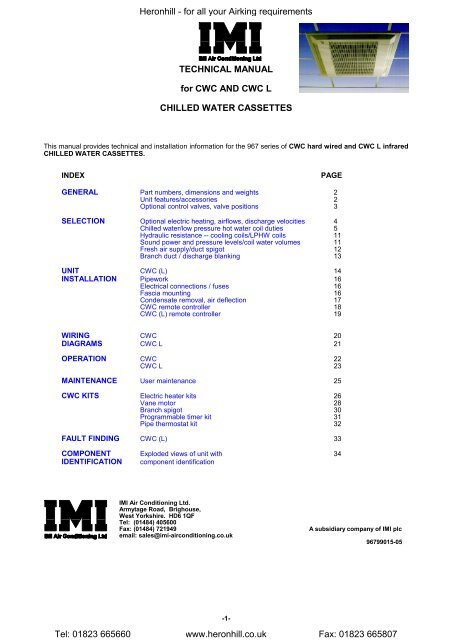
CWC and CWC L - Heronhill Air Conditioning Ltd
CWC and CWC L - Heronhill Air Conditioning Ltd
CWC and CWC L - Heronhill Air Conditioning Ltd

Create successful ePaper yourself
Turn your PDF publications into a flip-book with our unique Google optimized e-Paper software.
<strong>CWC</strong> 55 COOLING DUTIES<strong>Heronhill</strong> - for all your <strong>Air</strong>king requirementsMinimum Speed Medium Speed Maximum SpeedRoom <strong>Air</strong> On CW Temperature 0.150m 3 /s 0.192m 3 /s 0.273m 3 /sdb C wb C IN C OUT C Total Sensible Total Sensible Total Sensible27 19 6 11 4.04 2.74 4.95 3.38 6.45 4.4921 15 5 9 2.66 2.03 3.30 2.53 4.34 3.3821 15 5 11 1.73 1.61 1.91 1.91 2.32 2.3221 15 5 13 1.45 1.45 1.68 1.68 2.02 2.0221 15 7 11 1.59 1.55 2.28 2.07 3.11 2.8221 15 7 13 1.36 1.36 1.58 1.58 1.92 1.9221 15 7 15 1.18 1.18 1.36 1.36 1.63 1.6321 15 9 13 1.28 1.28 1.49 1.49 2.21 2.2121 15 9 15 1.09 1.09 1.26 1.26 1.52 1.5221 15 9 17 0.91 0.91 1.05 1.05 1.25 1.2524 17 5 9 3.72 2.58 4.55 3.17 5.93 4.2124 17 5 11 2.35 1.96 2.62 2.32 4.58 3.6024 17 5 13 1.99 1.81 2.19 2.14 2.62 2.6224 17 7 11 2.98 2.24 3.65 2.76 4.77 3.6824 17 7 13 1.84 1.75 2.07 2.07 2.83 2.8324 17 7 15 1.59 1.59 1.84 1.84 2.22 2.2224 17 9 13 2.11 1.86 2.66 2.34 3.51 3.1424 17 9 15 1.50 1.50 1.74 1.74 2.12 2.1224 17 9 17 1.31 1.31 1.52 1.52 1.83 1.8327 19 5 9 4.77 3.09 5.82 3.79 7.55 4.9927 19 5 11 3.93 2.70 4.88 3.35 6.42 4.4827 19 5 13 2.64 2.15 2.91 2.53 3.27 3.2027 19 7 11 4.06 2.75 4.95 3.38 6.42 4.4827 19 7 13 3.00 2.30 3.88 2.92 5.17 3.9427 19 7 15 2.12 1.95 2.33 2.31 2.82 2.8227 19 9 13 3.30 2.42 4.02 2.98 5.21 3.9627 19 9 15 1.97 1.89 2.23 2.23 3.72 3.3627 19 9 17 1.72 1.72 1.99 1.99 2.42 2.4229 19 5 9 4.84 3.44 5.89 4.22 7.65 5.5729 19 5 11 4.03 3.06 4.99 3.79 6.54 5.0629 19 5 13 2.72 2.49 3.00 2.95 4.85 4.3429 19 7 11 4.13 3.10 5.04 3.81 6.53 5.0629 19 7 13 3.17 2.68 4.02 3.37 5.32 4.5329 19 7 15 2.27 2.27 2.64 2.64 3.52 3.5229 19 9 13 3.38 2.77 4.12 3.41 5.33 4.5429 19 9 15 2.18 2.18 2.87 2.87 3.97 3.9729 19 9 17 1.99 1.99 2.31 2.31 2.82 2.82<strong>CWC</strong> 55 HEATING DUTIESMinimum Speed Medium Speed Maximum SpeedRoom <strong>Air</strong> On LPHW Temperature 0.150m 3 /s 0.192m 3 /s 0.273m 3 /sdb C wb C/%RH IN C OUT C Total Total Total20 12 82 71 4.01 4.69 5.8010 50% 90 80 5.50 6.42 7.9510 50% 90 75 5.18 6.05 7.4910 50% 80 70 4.72 5.51 6.8110 50% 80 65 4.35 5.10 6.3410 50% 65 55 3.51 4.11 5.1010 50% 65 50 3.01 3.57 4.4915 50% 90 80 5.10 5.95 7.3715 50% 90 75 4.77 5.58 6.9115 50% 80 70 4.32 5.04 6.2415 50% 80 65 3.94 4.62 5.7515 50% 65 55 3.10 3.64 4.5215 50% 65 50 2.54 3.05 3.8720 50% 90 80 4.69 5.48 6.7920 50% 90 75 4.36 5.11 6.3420 50% 80 70 3.91 4.58 5.6720 50% 80 65 3.52 4.14 5.1720 50% 65 55 2.69 3.16 3.9420 50% 65 50 1.86 2.49 3.2425 50% 90 80 4.29 5.02 6.2125 50% 90 75 3.95 4.63 5.7625 50% 80 70 3.51 4.11 5.1025 50% 80 65 3.10 3.66 4.5825 50% 65 55 2.27 2.68 3.3625 50% 65 50 1.57 1.75 2.53-6-Tel: 01823 665660 www.heronhill.co.uk Fax: 01823 665807
<strong>CWC</strong> 75 COOLING DUTIES<strong>Heronhill</strong> - for all your <strong>Air</strong>king requirementsMinimum Speed Medium Speed Maximum SpeedRoom <strong>Air</strong> On CW Temperature 0.217m 3 /s 0.283m 3 /s 0.368m 3 /sdb C wb C IN C OUT C Total Sensible Total Sensible Total Sensible27 19 6 11 5.44 3.74 6.62 4.62 7.90 5.6321 15 5 9 3.65 2.81 4.46 3.48 5.35 4.2721 15 5 11 2.05 2.05 2.37 2.37 3.23 3.2321 15 5 13 1.80 1.80 2.06 2.06 2.33 2.3321 15 7 11 2.56 2.32 3.19 2.91 3.85 3.6021 15 7 13 1.70 1.70 1.95 1.95 2.22 2.2221 15 7 15 1.45 1.45 1.66 1.66 1.87 1.8721 15 9 13 1.67 1.67 2.28 2.28 2.87 2.8721 15 9 15 1.35 1.35 1.55 1.55 1.75 1.7521 15 9 17 1.12 1.12 1.27 1.27 1.42 1.4224 17 5 9 5.00 3.51 6.08 4.32 7.26 5.2724 17 5 11 3.73 2.93 4.71 3.71 5.72 4.5824 17 5 13 2.31 2.31 2.67 2.67 3.03 3.0324 17 7 11 4.02 3.06 4.89 3.79 5.84 4.6324 17 7 13 2.22 2.22 2.96 2.96 3.97 3.8524 17 7 15 1.97 1.97 2.26 2.26 2.57 2.5724 17 9 13 2.94 2.60 3.60 3.24 4.29 3.9824 17 9 15 1.87 1.87 2.16 2.16 3.03 3.0324 17 9 17 1.62 1.62 1.86 1.86 2.10 2.1027 19 5 9 6.39 4.18 7.75 5.13 9.23 6.2227 19 5 11 5.39 3.72 6.59 4.60 7.90 5.6327 19 5 13 3.04 2.75 3.30 3.27 6.02 4.8527 19 7 11 5.43 3.74 6.58 4.60 7.83 5.6027 19 7 13 4.31 3.25 5.31 4.06 6.37 4.9927 19 7 15 2.48 2.48 2.87 2.87 3.90 3.9027 19 9 13 4.42 3.30 5.34 4.07 6.35 4.9827 19 9 15 2.90 2.69 3.83 3.47 4.66 4.3227 19 9 17 2.14 2.14 2.46 2.46 2.80 2.8029 19 5 9 6.47 4.66 7.84 5.73 9.34 6.9729 19 5 11 5.50 4.20 6.72 5.21 8.04 6.3829 19 5 13 3.19 3.19 5.03 4.49 6.24 5.6229 19 7 11 5.53 4.21 6.69 5.20 7.95 6.3429 19 7 13 4.46 3.74 5.46 4.67 6.53 5.7429 19 7 15 2.84 2.84 3.72 3.72 4.88 4.8829 19 9 13 4.52 3.77 5.47 4.67 6.48 5.7229 19 9 15 3.23 3.23 4.09 4.09 5.08 5.0829 19 9 17 2.49 2.49 2.87 2.87 4.11 4.11<strong>CWC</strong> 75 HEATING DUTIESMinimum Speed Medium Speed Maximum SpeedRoom <strong>Air</strong> On LPHW Temperature 0.217m 3 /s 0.283m 3 /s 0.368m 3 /sdb C wb C/%RH IN C OUT C Total Total Total20 12 82 71 5.05 5.93 6.9110 50% 90 80 6.92 8.12 9.4610 50% 90 75 6.53 7.65 8.9010 50% 80 70 5.94 6.96 8.1110 50% 80 65 5.51 6.47 7.5410 50% 65 55 4.44 5.21 6.0710 50% 65 50 3.87 4.59 5.3915 50% 90 80 6.41 7.52 8.7715 50% 90 75 6.02 7.06 8.2215 50% 80 70 5.43 6.37 7.4215 50% 80 65 4.99 5.88 6.8615 50% 65 55 3.93 4.62 5.4015 50% 65 50 3.32 3.96 4.6720 50% 90 80 5.91 6.94 8.0920 50% 90 75 5.51 6.48 7.5420 50% 80 70 4.93 5.79 6.7520 50% 80 65 4.48 5.28 6.1820 50% 65 55 3.42 4.03 4.7220 50% 65 50 2.74 3.32 3.9425 50% 90 80 5.41 6.35 7.4125 50% 90 75 5.00 5.89 6.8725 50% 80 70 4.44 5.21 6.0725 50% 80 65 3.96 4.68 5.4925 50% 65 55 2.90 3.44 4.0325 50% 65 50 1.85 2.61 3.17-7-Tel: 01823 665660 www.heronhill.co.uk Fax: 01823 665807
<strong>CWC</strong> 95 COOLING DUTIES<strong>Heronhill</strong> - for all your <strong>Air</strong>king requirementsMinimum Speed Medium Speed Maximum SpeedRoom <strong>Air</strong> On CW Temperature 0.217m 3 /s 0.283m 3 /s 0.378m 3 /sdb C wb C IN C OUT C Total Sensible Total Sensible Total Sensible27 19 6 11 6.82 4.51 8.53 5.67 10.71 7.2021 15 5 9 4.66 3.41 5.85 4.30 7.37 5.4821 15 5 11 2.91 2.59 4.32 3.58 5.69 4.6921 15 5 13 2.39 2.37 2.79 2.79 3.28 3.2821 15 7 11 3.51 2.87 4.44 3.63 5.61 4.6521 15 7 13 2.22 2.22 2.63 2.63 3.60 3.6021 15 7 15 1.94 1.94 2.27 2.27 2.65 2.6521 15 9 13 2.25 2.25 2.93 2.93 3.80 3.8021 15 9 15 1.78 1.78 2.10 2.10 2.46 2.4621 15 9 17 1.50 1.50 1.74 1.74 2.02 2.0224 17 5 9 6.18 4.20 7.73 5.28 9.71 6.7024 17 5 11 5.19 3.73 6.57 4.73 8.32 6.0424 17 5 13 3.37 2.92 3.77 3.51 6.24 5.1224 17 7 11 5.08 3.67 6.36 4.63 7.99 5.8924 17 7 13 3.85 3.13 5.03 4.04 6.43 5.2024 17 7 15 2.59 2.59 3.05 3.05 3.60 3.6024 17 9 13 3.89 3.14 4.89 3.89 6.16 5.0824 17 9 15 2.44 2.44 3.14 3.14 4.28 4.2824 17 9 17 2.15 2.15 2.53 2.53 3.96 2.9627 19 5 9 7.76 4.97 9.69 6.23 12.15 7.8827 19 5 11 6.92 4.56 8.67 5.74 10.91 7.2927 19 5 13 5.68 3.99 7.31 5.12 9.30 6.5727 19 7 11 6.67 4.44 8.34 5.58 10.44 7.0827 19 7 13 5.75 4.03 7.23 5.09 9.10 6.4827 19 7 15 3.60 3.13 5.58 4.39 7.28 5.7127 19 9 13 5.52 3.92 6.90 4.94 8.65 6.2827 19 9 15 4.46 3.48 5.66 4.42 7.16 5.6627 19 9 17 2.80 2.80 3.31 3.31 4.65 4.6529 19 5 9 7.85 5.50 9.81 6.91 12.31 8.7629 19 5 11 7.04 5.10 8.82 6.43 11.11 8.1929 19 5 13 5.88 4.57 7.53 5.83 9.58 7.4929 19 7 11 6.77 4.97 8.47 6.26 10.62 7.9629 19 7 13 5.89 4.57 7.40 5.78 9.33 7.3729 19 7 15 3.74 3.66 5.89 5.13 7.61 6.6429 19 9 13 5.63 4.45 7.05 5.62 8.84 7.1629 19 9 15 4.63 4.03 5.87 5.12 7.42 6.5629 19 9 17 3.24 3.24 4.27 4.27 5.73 5.73<strong>CWC</strong> 95 HEATING DUTIESMinimum Speed Medium Speed Maximum SpeedRoom <strong>Air</strong> On LPHW Temperature 0.217m 3 /s 0.283m 3 /s 0.378m 3 /sdb C wb C/%RH IN C OUT C Total Total Total20 12 82 71 5.05 5.93 7.0110 50% 90 80 6.92 8.12 9.6110 50% 90 75 6.53 7.65 9.0410 50% 80 70 5.94 6.96 8.2310 50% 80 65 5.51 6.47 7.6610 50% 65 55 4.44 5.21 6.1710 50% 65 50 3.87 4.59 5.4815 50% 90 80 6.41 7.52 8.9115 50% 90 75 6.02 7.06 8.3515 50% 80 70 5.43 6.37 7.5415 50% 80 65 4.99 5.88 6.9715 50% 65 55 3.93 4.62 5.4815 50% 65 50 3.32 3.96 4.7520 50% 90 80 5.91 6.94 8.2120 50% 90 75 5.51 6.48 7.6620 50% 80 70 4.93 5.79 6.8520 50% 80 65 4.48 5.28 6.2820 50% 65 55 3.42 4.03 4.7920 50% 65 50 2.74 3.32 4.0125 50% 90 80 5.41 6.35 7.5225 50% 90 75 5.00 5.89 6.9725 50% 80 70 4.44 5.21 6.1725 50% 80 65 3.96 4.68 5.5825 50% 65 55 2.90 3.44 4.1025 50% 65 50 1.85 2.61 3.23-8-Tel: 01823 665660 www.heronhill.co.uk Fax: 01823 665807
<strong>CWC</strong> 125 COOLING DUTIES<strong>Heronhill</strong> - for all your <strong>Air</strong>king requirementsMinimum Speed Medium Speed Maximum SpeedRoom <strong>Air</strong> On CW Temperature 0.368m 3 /s 0.472m 3 /s 0.656m 3 /sdb C wb C IN C OUT C Total Sensible Total Sensible Total Sensible27 19 6 11 8.73 6.11 10.34 7.37 12.61 9.3521 15 5 9 5.91 4.62 7.03 5.60 8.62 7.1421 15 5 11 3.01 3.01 4.51 4.49 5.99 5.9921 15 5 13 2.61 2.61 2.93 2.93 3.36 3.3621 15 7 11 4.28 3.88 5.10 4.74 6.24 6.1021 15 7 13 2.48 2.48 2.80 2.80 4.72 4.7221 15 7 15 2.11 2.11 2.36 2.36 2.69 2.6921 15 9 13 3.09 3.09 3.82 3.82 4.94 4.9421 15 9 15 1.96 1.96 2.21 2.21 2.54 2.5421 15 9 17 1.61 1.61 1.79 1.79 2.03 2.0324 17 5 9 7.99 5.70 9.47 6.88 11.56 8.7124 17 5 11 6.41 4.99 7.68 6.08 9.48 7.8024 17 5 13 3.39 3.39 3.82 3.82 6.40 6.4024 17 7 11 6.44 5.00 7.62 6.06 9.28 7.7224 17 7 13 4.45 4.16 5.50 5.17 6.86 6.7224 17 7 15 2.87 2.87 3.23 3.23 4.92 4.9224 17 9 13 4.76 4.29 5.62 5.22 6.82 6.7124 17 9 15 2.74 2.74 4.17 4.17 5.53 5.5324 17 9 17 2.36 2.36 2.65 2.65 3.03 3.0327 19 5 9 10.15 6.75 11.99 8.11 14.67 10.2427 19 5 11 8.78 6.13 10.43 7.41 12.79 9.4227 19 5 13 6.81 5.29 8.30 6.52 10.34 8.4227 19 7 11 8.62 6.06 10.16 7.30 12.36 9.2427 19 7 13 7.12 5.42 8.46 6.58 10.34 8.4227 19 7 15 3.65 3.65 5.60 5.47 7.41 7.2927 19 9 13 7.00 5.37 8.24 6.50 9.95 8.2727 19 9 15 5.25 4.67 6.28 5.73 7.68 7.3927 19 9 17 3.13 3.13 3.53 3.53 6.06 6.0629 19 5 9 10.23 7.52 12.07 9.06 14.74 11.4829 19 5 11 8.89 6.91 10.54 8.37 12.88 10.6829 19 5 13 7.01 6.10 8.48 7.50 10.49 9.6929 19 7 11 8.72 6.83 10.26 8.25 12.44 10.4929 19 7 13 7.26 6.20 8.59 7.54 10.46 9.6729 19 7 15 5.21 5.21 6.56 6.56 8.58 8.5829 19 9 13 7.11 6.14 8.35 7.44 10.05 9.5129 19 9 15 5.46 5.46 6.68 6.68 8.60 8.6029 19 9 17 4.27 4.27 5.61 5.61 7.42 7.42<strong>CWC</strong> 125 HEATING DUTIESMinimum Speed Medium Speed Maximum SpeedRoom <strong>Air</strong> On LPHW Temperature 0.368m 3 /s 0.472m 3 /s 0.656m 3 /sdb C wb C/%RH IN C OUT C Total Total Total20 12 82 71 8.61 10.00 12.1010 50% 90 80 11.70 13.58 16.4410 50% 90 75 11.12 12.90 15.6110 50% 80 70 10.07 11.68 14.1410 50% 80 65 9.48 11.00 13.3010 50% 65 55 7.62 8.83 10.6810 50% 65 50 6.99 8.13 9.8315 50% 90 80 10.85 12.60 15.2615 50% 90 75 10.28 11.93 14.4415 50% 80 70 9.23 10.71 12.9715 50% 80 65 8.65 10.04 12.1415 50% 65 55 6.79 7.88 9.5315 50% 65 50 6.14 7.16 8.6820 50% 90 80 10.01 11.63 14.0920 50% 90 75 9.45 10.97 13.2720 50% 80 70 8.40 9.75 11.8120 50% 80 65 7.83 9.08 10.9820 50% 65 55 5.97 6.93 8.3820 50% 65 50 5.29 6.18 7.5225 50% 90 80 9.18 10.66 12.9325 50% 90 75 8.62 10.00 12.1125 50% 80 70 7.57 8.79 10.6525 50% 80 65 7.00 8.13 9.8325 50% 65 55 5.15 5.99 7.2425 50% 65 50 4.43 5.19 6.34-9-Tel: 01823 665660 www.heronhill.co.uk Fax: 01823 665807
<strong>CWC</strong> 185 COOLING DUTIES<strong>Heronhill</strong> - for all your <strong>Air</strong>king requirementsMinimum Speed Medium Speed Maximum SpeedRoom <strong>Air</strong> On CW Temperature 0.378m 3 /s 0.481m 3 /s 0.665m 3 /sdb C wb C IN C OUT C Total Sensible Total Sensible Total Sensible27 19 6 11 11.55 7.69 14.12 9.44 18.13 12.2921 15 5 9 7.86 5.79 9.64 7.14 12.45 9.3421 15 5 11 4.31 4.17 4.85 4.85 9.14 7.8221 15 5 13 3.71 3.71 4.24 4.24 4.97 4.9721 15 7 11 5.83 4.84 7.23 6.02 9.39 7.9221 15 7 13 3.50 3.50 4.01 4.01 4.75 4.7521 15 7 15 3.00 3.00 3.42 3.42 3.99 3.9921 15 9 13 3.66 3.66 4.78 4.78 6.43 6.4321 15 9 15 2.78 2.78 3.18 3.18 3.74 3.7421 15 9 17 2.30 2.30 2.60 2.60 3.02 3.0224 17 5 9 10.50 7.16 12.83 8.80 16.48 11.4524 17 5 11 8.57 6.25 10.67 7.78 13.89 10.2424 17 5 13 4.95 4.69 5.48 5.48 6.48 6.4824 17 7 11 8.59 6.26 10.51 7.71 13.52 10.0724 17 7 13 4.61 4.55 7.91 6.56 10.55 8.7724 17 7 15 4.06 4.06 4.65 4.65 5.48 5.4824 17 9 13 6.52 5.34 8.02 6.61 10.35 8.6924 17 9 15 3.85 3.85 4.43 4.43 7.10 7.1024 17 9 17 3.35 3.35 3.83 3.83 4.49 4.4927 19 5 9 13.23 7.49 16.13 10.40 20.65 13.4727 19 5 11 11.65 7.73 14.28 9.52 18.40 12.4127 19 5 13 6.56 5.54 11.61 8.32 15.35 11.0627 19 7 11 11.36 7.59 13.85 9.32 17.72 12.1027 19 7 13 9.61 6.81 11.83 8.42 15.27 11.0227 19 7 15 5.28 5.05 5.89 5.89 11.66 9.5327 19 9 13 9.37 6.70 11.44 8.25 14.65 10.7627 19 9 15 7.26 5.82 9.11 7.28 11.87 9.6227 19 9 17 4.40 4.40 5.06 5.06 5.98 5.9829 19 5 9 13.39 9.41 16.34 11.55 20.94 15.0129 19 5 11 11.87 8.67 14.55 10.69 18.75 13.7929 19 5 13 9.43 7.56 12.05 9.55 15.86 12.6629 19 7 11 11.54 8.52 14.08 10.47 18.03 13.6429 19 7 13 9.87 7.76 12.14 9.59 15.67 12.5829 19 7 15 5.83 5.83 8.88 8.21 12.33 11.1729 19 9 13 9.57 7.62 11.69 9.39 14.98 12.2829 19 9 15 7.62 6.79 9.50 8.46 12.35 11.1829 19 9 17 5.11 5.11 5.89 5.89 9.54 9.54<strong>CWC</strong> 185 HEATING DUTIESMinimum Speed Medium Speed Maximum SpeedRoom <strong>Air</strong> On LPHW Temperature 0.378m 3 /s 0.481m 3 /s 0.665m 3 /sdb C wb C/%RH IN C OUT C Total Total Total20 12 82 71 8.75 10.11 12.2010 50% 90 80 11.89 13.73 16.5710 50% 90 75 11.30 13.05 15.7310 50% 80 70 10.23 11.82 14.2510 50% 80 65 9.64 11.12 13.4010 50% 65 55 7.74 8.93 10.7710 50% 65 50 7.11 8.22 9.9015 50% 90 80 11.03 12.74 15.3815 50% 90 75 10.45 12.07 14.5515 50% 80 70 9.38 10.83 13.0715 50% 80 65 8.79 10.15 12.2315 50% 65 55 6.90 7.97 9.6015 50% 65 50 6.25 7.24 8.7520 50% 90 80 10.18 11.76 14.2020 50% 90 75 9.60 11.09 13.3820 50% 80 70 8.53 9.86 11.9020 50% 80 65 7.95 9.18 11.0720 50% 65 55 6.07 7.01 8.4520 50% 65 50 5.38 6.25 7.5825 50% 90 80 9.33 10.78 13.0325 50% 90 75 8.76 10.12 12.2125 50% 80 70 7.69 8.89 10.7425 50% 80 65 7.12 8.22 9.9125 50% 65 55 5.24 6.05 7.3025 50% 65 50 4.51 5.25 6.39-10-Tel: 01823 665660 www.heronhill.co.uk Fax: 01823 665807
HYDRAULIC RESISTANCES<strong>Heronhill</strong> - for all your <strong>Air</strong>king requirementsSOUND POWER <strong>and</strong> SOUND PRESSURE LEVELS967 SERIES <strong>CWC</strong>SOUND POWER LEVELSFrequency HzSOUND PRESSURELEVELSMODEL SPEED 125 250 500 1K 2K 4K dBA dBA NC35557595125185Min 56.3 46.4 42.3 39.0 39.2 42.2 49.1 28.1 24Med 56.8 51.2 47.0 42.9 40.7 42.8 51.1 30.1 25Max 55.5 53.6 50.5 46.1 42.0 43.1 53.1 32.1 25Min 55.1 46.9 42.4 37.3 33.2 35.3 45.6 24.6 17Med 55.6 51.4 47.5 43.0 37.9 36.9 49.5 28.5 20Max 55.1 53.9 51.0 46.8 41.7 39.0 52.6 31.6 24Min 58.4 53.8 50.0 45.5 38.0 29.1 51.2 30.2 23Med 63.5 58.4 56.2 52.5 47.0 38.9 57.6 36.6 30Max 70.3 63.4 61.7 59.1 53.7 48.5 63.9 42.9 37Min 53.2 52.9 49.4 44.9 39.6 35.3 50.8 29.8 22Med 61.4 57.7 55.0 51.2 46.7 39.3 56.6 35.6 29Max 70.2 63.3 60.7 57.9 53.4 48.6 63.2 42.2 35Min 58.0 56.8 53.5 50.0 43.7 33.6 54.9 33.9 27Med 68.5 62.4 59.2 57.0 51.4 43.3 61.6 40.6 35Max 72.5 67.0 64.0 62.2 56.8 51.9 66.8 45.8 40Min 62.7 57.4 53.7 50.7 43.8 32.2 55.6 34.6 28Med 68.6 62.5 59.0 57.3 50.9 42.9 61.6 40.6 35Max 72.2 66.7 63.2 61.5 56.1 51.0 66.1 45.1 40Sound Power Levels were obtained in full conformity with BS 4196: Part 5: 1981. Quantities are shown in dB with ast<strong>and</strong>ard reference of 1 pW.Sound Pressure Levels are dB relative to 2 x 10 -5 N/m 2 <strong>and</strong> are calculated from the results under anechoic conditions <strong>and</strong>are quoted as an average of all points on a hemisphere of a radius of 3m away, 1m down from the centre of the unit.COIL WATER VOLUMES (Litres)Model 35 (L) 55 (L) 75 (L) 95 (L) 125 (L) 185 (L)Chilled Water 1.3 2.0 2.0 2.7 3.1 4.4LPHW Coil 1.0 1.0 1.0 1.0 1.2 1.2-11-Tel: 01823 665660 www.heronhill.co.uk Fax: 01823 665807
<strong>Heronhill</strong> - for all your <strong>Air</strong>king requirementsFRESH AIR SUPPLY/BRANCH DUCT<strong>CWC</strong> (L) units are fitted with panels which may be removed to allow the installer to provide the following:1 Fresh <strong>Air</strong> Inlet Supply 2 Branch duct to another area to be conditionedPanel positions are shown below. All dimensions are in millimetres.Dimensions B, C, 326 <strong>and</strong> 397 are to the centres of the branch duct panels.<strong>CWC</strong> 35/55/75/9 125/185A 723 1171B 383 364C 383 808D 101 106The fresh air supply duct should be connected to the corner opening (view on 'X') after removing the knockout; (do NOTremove any insulation OR cut into the polystyrene).The auxiliary fan must be sized to overcome the resistance of the filter, the ductwork <strong>and</strong> the <strong>CWC</strong> unit itself. Theadjacent graph shows the static resistance of the <strong>CWC</strong> unit against the required fresh air flow rate. (To preventexcessive noise, the maximum fresh air volume should be 5% of the nominal air volume for any given unit <strong>and</strong> fanspeed).The auxiliary fan should be connected to a separate electrical circuit, appropriately fused <strong>and</strong> isolated.-12-Tel: 01823 665660 www.heronhill.co.uk Fax: 01823 665807
Tel: 01823 665660 www.heronhill.co.uk Fax: 01823 665807<strong>Heronhill</strong> - for all your <strong>Air</strong>king requirementsBRANCH DUCTThe branch duct can be taken from any one of the four sides of the chassis.Ductwork should be fully insulated <strong>and</strong> supported throughout its entire length.The graphs below show the amount of conditioned air passed by a single branch duct.The air distribution of the unit will be changed when a branch duct is fitted, as follows:ModelFascia sideWithout branch ductfascia air discharge(% of total air volume)With branch ductfascia air discharge at ducted side(% of total air volume - minimum)35/55 Any 25 17.575/95 Any 25 17.5125/185Short side 18 12.5Short side 18 12.5Long side 32 27.0Long side 32 27.0As shown on the graphs above, branch duct airflow can be increased by blanking off the fascia side to which thebranch duct has been connected.DISCHARGE BLANKINGOn cool only air conditioners it is possible to blank off the airflow of any two of the four sides on 35, 55, 75 <strong>and</strong> 95models, both of the short sides or one of the long sides on 125 <strong>and</strong> 185 models.This will assist applications such as L shaped rooms etc..IMPORTANT NOTE:On units fitted with electric heating, DO NOT blank off any more than one vane length (halfa long side on 125 <strong>and</strong> 185 models) as this will restrict airflow over the heating elementscausing them to overheat.1 Fit the foam blanking piece prior to refitting the fascia.2 Select the side to be blocked.3 Wedge the foam blanking piece between the drain tray <strong>and</strong> the chassis ensuring that the lower surface is levelwith the bottom of the drain tray.-13-
<strong>Heronhill</strong> - for all your <strong>Air</strong>king requirements<strong>CWC</strong> CHILLED WATER CASSETTE INSTALLATIONThe <strong>CWC</strong> CHILLED WATER CASSETTE is designed to operate above a suspended false ceiling.THE INSTALLER SUPPLIES:4 lengths of screwed rod (M8, M10 or 3/8" OD) with 12 nuts, to suspend the chassis.Method of securing screwed rod to solid ceiling e.g. Rawl bolt shields.Insulated pipework.All mains wiring, with suitable isolation.Remote thermostat (available separately, part number 97200211).Condensate pump drain (12mm bore diameter tube).Interconnecting wires for the remote thermostat.UNPACKINGCarefully unfasten the box <strong>and</strong> fold open the cardboard flaps to gain access to the unit.The following are supplied:<strong>CWC</strong> Chassis (with suspension brackets fitted)Fascia (in a protective plastic sleeve)Cardboard template for marking out rodmounting centresEnvelope containing operatinginstructions for the end user8 washers -Use on suspension brackets2 cable clamps -external cable entries4 (8) M4 screws <strong>and</strong> captive washersFoam blanking piecePlug cover plate <strong>and</strong> fixing screw1 Lift the fascia inside its protective sleeve from the cardboard box, <strong>and</strong> keep protected whilst installing the chassis.NOTE:Take care not to damage the vane actuator, which may protrude from the inside of the fascia.2 Remove the plastic bag containing additional components from the corner of the box opposite the external electricsbox <strong>and</strong> also place in a safe location until required.3 Remove <strong>and</strong> discard the polystyrene packing pieces from around the chassis.4 Lift the chassis from the box using the suspension brackets.CHASSIS MOUNTINGNOTE: It is generally easier to fit kits prior to mounting the unit <strong>and</strong> connecting the pipework.Units are sized to allow each chassis to fit within a 1200mm x 1200mm suspended ceiling area; it is recommended thatthe ceiling is built with the unit in position.Units may be fitted into plasterboard ceilings, but access trapsfor the external electrics box, condensate pump <strong>and</strong> pipeworkmust be provided.Location of the unit will depend on the room shape, load <strong>and</strong>number of units installed. Typical options are shown right.It is also possible to block off airflow using the foam blanking piecebefore refitting the fascia; refer to page 13.1 Determine the position for the unit; the air inlet must be at least450mm above any obstruction. Also ensure that the chassis doesnot interfere with light fittings, sprinkler heads, etc..2 Identify the type of ceiling <strong>and</strong> ensure that the mounting surfacewill support the operating weight of the unit:-14-Tel: 01823 665660 www.heronhill.co.uk Fax: 01823 665807
<strong>Heronhill</strong> - for all your <strong>Air</strong>king requirementsMODEL 35 55 75 95 125 185OPERATING WEIGHT (kg) 35 40 44 48 70 773 If the unit is to be fitted after the ceiling has been installed, remove ceiling tiles to accept the chassis, plus adjacenttiles on each side for general access (Fig. 3).Fig. 3MODEL 35 55 75 95 125 185A (height above ceiling) 276 276 276 276 276 276B (height above suspension brkts.) 32 32 32 32 32 32C (mains cable entry position) 76 76 76 76 76 76D (pipe exit position) 43 43 43 43 47 474 The chassis should be supported by four screwed rods <strong>and</strong> 12 nuts (M8, M10 or 3/8"OD) supplied by the installer.Rod mounting centres are shown at + - + below; use the template provided to mark these out (Fig.4).Model 35 55 75 95 125 185A (Chassis width) 723 723 723 723 1171 1171B (Chassis depth) 723 723 723 723 723 723C (Aperture width) 770 770 770 770 1188 1188D (Aperture depth) 770 770 770 770 770 770E (Fascia width) 823 823 823 823 1271 1271F (Fascia depth) 823 823 823 823 823 823G (Rod mounting centres) 280 280 280 280 448 448Fig. 4.On plasterboard suspended ceilings, remove sufficient of theceiling to give clearance for the unit to be fitted, <strong>and</strong> for access topipework <strong>and</strong> electrics; a trap door should be left for serviceaccess to electrics <strong>and</strong> pipework.On reinforced concrete ceilings use Rawl bolt shields orequivalent.On wooden ceilings use battens for a mounting frame.5 If a heater kit is to be used, fit this prior to mounting the unit.-15-Tel: 01823 665660 www.heronhill.co.uk Fax: 01823 665807
<strong>Heronhill</strong> - for all your <strong>Air</strong>king requirements6 Hang the four mounting rods then remove the two suspension brackets from the chassis (retaining the six (ten)screws). Using twelve nuts <strong>and</strong> eight washers (washers supplied with the unit), support the suspension brackets sothat their top surface is approximately 280mm above the lower surface of the suspended ceiling (Fig. 5).Fig. 5.7 Suspend the chassis by locating the hooks on the side panels into the suspension brackets. Lock the nuts securely.8 Secure the chassis to the suspension brackets using the six (ten) retained screws, (3 each side).PIPEWORKPipework is terminated adjacent to the access panel <strong>and</strong> utilises 22mm diameter copper water pipe on single fan units(<strong>CWC</strong> 35 - 95) <strong>and</strong> 28mm copper water pipe on double fan units (<strong>CWC</strong> 125 - 185).LPHW coil pipes are 15mm diameter for all models.When brazing, mask the chassis to prevent burning of the insulation.When using flare fittings, always use two spanners to secure the flare connections to avoid distorting <strong>and</strong>damaging the pipework. The use of a little oil on the flaring tool <strong>and</strong> the mating surfaces will help.If valves have not already been fitted, fit them once the unit has been mounted in the ceilingPipe exit positions are shown on page 3.ELECTRICAL CONNECTIONSMains, control <strong>and</strong> connecting cables are supplied <strong>and</strong> fitted bythe installer.Wiring must be carried out in accordance with local <strong>and</strong> nationalcodes.Cables must be size compatible with the recommended fuse fora given unit (see below).An isolator switch should be positioned within easy reach of theindoor unit.The equipment must be earthed.Cable gl<strong>and</strong>s suitable for str<strong>and</strong>ed cables are supplied <strong>and</strong> shouldbe used to secure all cables. Installers must supply a method ofsecuring any solid sheathed cable.FUSES (A)Model 35 55 75 95 125 185Without Electric Heaters 5 5 5 5 5 5With Electric Heaters 13 13 13 13 2 x 16 2 x 16FASCIA MOUNTINGEnsure that the chassis is electrically isolated.1 On double fan units, remove the air outlet support packing(white exp<strong>and</strong>ed polystyrene inside a clear plastic sleeve)(Fig. 6).Fig. 6-16-Tel: 01823 665660 www.heronhill.co.uk Fax: 01823 665807
<strong>Heronhill</strong> - for all your <strong>Air</strong>king requirements2 Loosely fit two (four) M4 fascia fixing screws <strong>and</strong> captive washersat position B (Fig. 7).3 Unclip the grilles from the fascia by pushing the latches away fromthe fascia frame. Unhook <strong>and</strong> remove (Fig. 8).4 With the <strong>CWC</strong> badge at the plug end, (external electrics boxcorner), offer the fascia up to the chassis <strong>and</strong> rest in position on thescrews in the two (four) keyhole slots (shown in position B, Fig. 7).5 Connect the two plugs <strong>and</strong> sockets <strong>and</strong> fit the plug cover plateensuring that no wires are trapped.6 Fit the remaining fascia retaining screws in position A (Fig. 7) <strong>and</strong>gently tighten all four (eight) screws.Fig.7.CAUTION: Overtightening the screws will distort the fascia.7 Level the fascia with the ceiling by adjusting the nuts on the hanging rods.8 Hook the grilles into the fascia (Fig. 8) <strong>and</strong> swing up until thelatches click into position.NOTE: The grilles can be hinged from either side of thefascia, to suit the application.Fig. 8.CONDENSATE REMOVALCondensate is collected in a drain tray which runs around the full length of the coil.An outlet connection is provided above the access panel for connection to a 12mm bore flexible pipe.The unit is fitted with a condensate pump which can achieve a 5m lift.A length of (red) flexible pipe is moulded to the drain tray for emptying the drain tray prior to removal for maintenance.This is clipped to the access panel. Do NOT connect the condensate drain to this pipe or try to remove it.AIR DEFLECTIONThe air off vanes can be adjusted by h<strong>and</strong> to the required level of deflection.A vane motor kit is available (part number 96700400) which should only be fitted to units with heating available. Whenfitted the vanes are motorised <strong>and</strong> linked.In cooling or dead b<strong>and</strong> (neither heating nor cooling), the discharge air is directed horizontally along the ceiling.In heating, the vanes move automatically to direct warm air downwards.-17-Tel: 01823 665660 www.heronhill.co.uk Fax: 01823 665807
<strong>CWC</strong> REMOTE CONTROLLER.<strong>Heronhill</strong> - for all your <strong>Air</strong>king requirementsThe thermostat should be wired with 7 cores of double insulated cable, 0.5mm 2 minimum, preferably in plastic conduitfor good appearance.Select a position to mount the thermostat taking into account the following comments:abcdefThe thermostat must be mounted on a flat surface within the area conditioned by the unit to which it is connected.Avoid draughts, heat from radiators, temperature variations from hot/cold water pipes <strong>and</strong> direct sunlight.Avoid corners of the room where air is likely to stagnate.Avoid direct air discharge from the unit nto the controller.Avoid positions where the thermostat may be covered or obscured.If the room contains pillars, mount on the side of the pillar furthest away from the unit.Heating is only possible if the unit is supplied from a heat pump chiller, or if electric heaters have been fitted.REMOTE CONTROL 96000320 (7204)--o--o--O--O--O--o--o--Carefully prise off the push-fit dial on the remote controller, unscrew the retaining screw <strong>and</strong> remove the control cover.Mount the controller directly to a wall or onto a plinth, using two suitable fasteners, (not supplied).Wire between the remote controller <strong>and</strong> the unit using multi-core cable, as shown in the wiring diagram (page 20).SETTING INSTRUCTIONS:The cooling differential (cool in to cool out) is fixed at 1.8 C +/- 0.5 C.The heating differential (heat in to heat out) is fixed at 1.5C +/- 0.5C.The deadb<strong>and</strong> is fixed at 1.2 +/- 0.7C.The set point limits can be adjusted on the back of the push fit dial. The set point is factory set for a range from 17Cto 30C: it is recommended that the minimum setting is kept at 17C or above.REMOTE CONTROL 97200211 (RCC 30)--o--o--O--O--O--o--o--Using a flat-bladed screwdriver in the slot at the bottom of the casing, lever off the cover.Mount the backpanel directly to a wall or onto a plinth, using the fasteners supplied.Wire between the remote controller <strong>and</strong> the unit as shown.OPERATION RETURN AIR SENSOR NEUTRAL LIVE HEAT COOL MAX MED MINRCC 30 B1, M N L Y11 Y21 Q3 Q2 Q1<strong>CWC</strong> *97200212 N 2 H 6 3 4 5*Optional return air sensor 97200212 can detect return air temperature at the unit rather than the controller.-18-Tel: 01823 665660 www.heronhill.co.uk Fax: 01823 665807
DIP switches at the bottom rear of the controller can be set on site to suit the application.DIP switch Function ON position OFF position1 Fan control Fan control is temperature dependent in alloperating modes2 Operating mode changeover viaexternal switch3 Action of switch for externallyoperated mode changeover<strong>Heronhill</strong> - for all your <strong>Air</strong>king requirementsChangeover between normal operation <strong>and</strong>energy saving modeChangeover activated when contact ofswitch is closedFan control in normal operation istemperature independentChangeover between normal operation <strong>and</strong>st<strong>and</strong>byChangeover activated when contact ofswitch is open4 St<strong>and</strong>by Frost protection disabled Frost protection enabled5 Switching differential 1K in heating mode, 0.5K in cooling mode 4K in heating mode, 2K in cooling mode6 Dead zone in normal operation 2K 5K= factory settings--o--o--O--O--O--o--o--<strong>CWC</strong> L REMOTE CONTROLLER.<strong>CWC</strong> L indoor units are operated by an infrared remote controller, supplied as an accessory with a wall mountingbracket, PP3 (9 volt) battery, screws <strong>and</strong> wall plugs.The controller operates remotely by infrared signals: operation is shown on page 23.INFRARED OPERATIONOpen the battery cover at the bottom rear of the controller by sliding out <strong>and</strong> hingingup, push the polarised connector onto the battery, slot into the controller <strong>and</strong> closethe cover. The controller is now ready for operation as stated in the user h<strong>and</strong>book.For convenience, the wall mounting bracket may be secured to a wall <strong>and</strong> used topark the controller.--o--o--O--O--O--o--o---19-Tel: 01823 665660 www.heronhill.co.uk Fax: 01823 665807
Tel: 01823 665660 www.heronhill.co.uk Fax: 01823 665807<strong>Heronhill</strong> - for all your <strong>Air</strong>king requirementsCHILLED WATER CASSETTE <strong>CWC</strong> 125 - 185 WIRING DIAGRAMCHILLED WATER CASSETTE <strong>CWC</strong> 125 - 185 WIRING DIAGRAM-21-
Tel: 01823 665660 www.heronhill.co.uk Fax: 01823 665807<strong>Heronhill</strong> - for all your <strong>Air</strong>king requirementsOPERATING INSTRUCTIONS 96000320 (7204 ELECTROMECHANICAL)TEMPERATURE CONTROLThe temperature range is factory set 17C - 30C.Turning anti-clockwise for lower room temperatures, turn clockwise for higher room temperatures.The white neon is lit when the unit is in cooling mode.The amber neon is lit when the unit is in heating mode (if heating is fitted).Heating is possible if the system includes a heat pump outdoor unit, or electric heaters have been fitted.Neither neon is lit when the thermostat is between cooling <strong>and</strong> heating.--o--o--O--O--O--o--o--OPERATING INSTRUCTIONS 97200211 (RCC 30 ELECTRONIC)TEMPERATURE CONTROLThe temperature range is factory set 17C - 30C.Turning anti-clockwise for lower room temperatures, turn clockwise for higher room temperatures.Heating is possible if the system includes a heat pump outdoor unit, or electric heaters have been fitted.--o--o--O--O--O--o--o---22-
<strong>CWC</strong> L INFRARED REMOTE CONTROLLER<strong>Heronhill</strong> - for all your <strong>Air</strong>king requirements• The h<strong>and</strong>set should be pointed towards the unit.• Two seconds after the last button press, the whole displayed programme is automatically transmitted.• The unit responds with 2 beeps, (except ON/OFF comm<strong>and</strong>s - one beep).• The transmit symbol A flashes whilst transmission is taking place.• Displayed values may be re-sent at any time by pressing the pink H button twice.1 Remote Controller Power UpRemove the battery cover <strong>and</strong> insert two "AAA" size 1.5V batteries.The initial display will show:COOLHIGH FAN SPEEDTEMPERATURETIME2 Setting Cool/Heat/Dry Modes'ON' TIMER SWITCHED OFF'OFF' TIMER SWITCHED OFFCOOL- Unit cools when required but cannot heatDRY- Unit removes moisture by cycling cooling at low speed,humidity is reduced, but room temperature is not changed.FAN ONLY - No cooling or heating - fan onlyHEAT- If heating is available, unit heats when required but cannot cool.AUTO COOL/HEAT - Unit cools or heats when required (if heating is available)3 Setting the Fan SpeedsRepeated pressing of the 'fan speed selection' button selects low, medium, high <strong>and</strong> auto speeds. In 'auto' selection, the fan runsat high speed when there is a difference of more than 2C between the room temperature <strong>and</strong> the set (required) temperature, <strong>and</strong>low speed when less than 2C.4 Setting the TemperaturePress the ‘up’ or ‘down’ 'set temperature' button to alter the display between 16C <strong>and</strong> 30C.By holding both buttons down, the display is changed between C <strong>and</strong> F.5 Setting the Clock (Current time)The ‘up’ <strong>and</strong> ‘down’ buttons must be held down for 3 seconds before they operate. Continue to hold the button down for rapidchange.-23-Tel: 01823 665660 www.heronhill.co.uk Fax: 01823 665807
<strong>Heronhill</strong> - for all your <strong>Air</strong>king requirements6 Programming the TimerThe 24 hour timer can have one ON comm<strong>and</strong> or one OFF comm<strong>and</strong> or one ON/OFF cycle in a 24 hour period. Blank ON <strong>and</strong>OFF timer windows indicate that the timer is not programmed.7 Setting the ON TimePress the TIMER ON set ‘S’ button <strong>and</strong> step to the required ON time. Hold the button down for repeated stepping. Press theTIMER ON ‘C’ button to cancel the ON time.8 Setting the OFF TimePress the TIMER OFF ‘S’ button <strong>and</strong> step to the required OFF time. Hold the button down for repeated stepping. Press the TIMEROFF ‘C’ button to cancel the OFF time.9 Only ON Time SelectedUnit will turn ON at the selected time <strong>and</strong> stay ON.10 Only OFF Time SelectedUnit will turn OFF at the selected time <strong>and</strong> stay OFF.11 Use of the Pink H ON/STANDBY button when time programmes are selectedAt any time, pressing the Pink button will either start the unit or return it to st<strong>and</strong>by mode. The unit will remain at this conditionunless an appropriate ON or OFF time has been programmed.12 Cold StartIn Cool or Heat mode, not Auto, after more than 3 days without power, or after 2 hours of non-operation, the set temperature isautomatically raised (in heating mode) or lowered (in cooling mode) by 2C until this temperature is reached or the unit has run for20 minutes after which the unit operates with the displayed temperature. This decreases the time taken to reach set point.13 Fan Speed ( heat pump systems only)In heat pump systems, the indoor fan always starts at low speed in heating mode, <strong>and</strong> changes to the selected speed when theindoor coil is warm, returning to low speed when not calling for heating.14 Off cycle delayTo prevent operational problems, cooling restart is delayed for 3 minutes following power up, or from the time the unit was lastcooling or heating, (if heat pump). Cooling or heating, (if heat pump) will operate for a minimum of 1.5 minutes.15 Displays/DiagnosticsCool Dry Fan HeatD I 4 F DIAGNOSTICSGreen Red Red AmberOFF OFF OFF OFFNo power, manual OFF, timed OFF, condensatehigh level, fault in condensate controlON OFF OFF OFF Cooling mode selectedON OFF OFF FLASHING AUTO - predominantly CoolingOFF OFF OFF ON Heating mode selectedFLASHING OFF OFF ON AUTO - predominantly HeatingOFF OFF ON OFF Fan mode selectedOFF ON OFF OFF Dry mode selectedFLASHING ON ON ONa. Compressor not running (DX systems only)b. Indoor coil sensor open/short circuitON ON ON FLASHINGOutdoor coil sensor (resistor if air conditioner)open/short circuitOFF OFF OFF FLASHING Heat Pumps Only - defrost in progress <strong>and</strong>FLASHING OFF OFF FLASHINGindoor fan will stopON ON FLASHING ON Room sensor open/short circuitOFF FLASHING OFF OFFDe-icing in progressOFF FLASHING OFF FLASHING16 Heat Pump OnlyIf the outdoor coil temperature reaches 65C, the compressor <strong>and</strong> outdoor fan will stop until the coil cools to 55C.17 Comm<strong>and</strong>s Refuseda. Attempts to set temperatures outside the display range are not transmitted.b. If heating comm<strong>and</strong>s are refused, the installer's programming is incorrect - call the engineer.18 Battery ReplacementIt is advisable to replace the batteries as soon as the display begins to fade. Correct transmission cannot be guaranteed if thebattery is failing.19 Power CutsIf the unit loses power for more than three days it may default to the following conditions <strong>and</strong> desired settings will need to betransmitted from the h<strong>and</strong>set.Room temperature greater than 20C:Cooling mode, high fan speed, 24C, time 12:00 midnight, timers offRoom temperature less than 20C:Heating mode, high fan speed, 20C, time 12:00 midnight, timers offFor shorter power losses, the system defaults to the previous settings when power is returned. During power loss the clock <strong>and</strong>timers do not operate, so will need to be reset. When mains power is returned there is a delay of 30 seconds before the unitcan accept comm<strong>and</strong>s from the h<strong>and</strong>set.20 User MaintenanceIsolate the unit at the mains supply before commencing any maintenance work.The unit should always be used with a filter. In order to maintain efficiency it is important that the filter behind the air intake grilleis cleaned regularly:! Remove the filter(s) from behind the air intake grille.! Wash the filter (in tepid water only) <strong>and</strong> shake dry before use.! Alternatively tap the filter gently to remove dust or vacuum clean.! To clean the unit use soap or a non-scratch liquid cleaner.-24-Tel: 01823 665660 www.heronhill.co.uk Fax: 01823 665807
USER MAINTENANCEISOLATE THE UNIT ELECTRICALLY BEFORE COMMENCING ANY MAINTENANCE WORKIn order to maintain maximum efficiency of this unit, it is important that the filters behind the return air grilles arecleaned regularly.To remove filters;<strong>Heronhill</strong> - for all your <strong>Air</strong>king requirements1 Unclip the grilles from the fascia by pushing the latchesaway from the fascia frame.2 Swing the grilles open <strong>and</strong> unlatch at the opposite end;remove with the filters intact.3 Remove the filters from the grilles <strong>and</strong> clean by washingin tepid water, vacuuming or by tapping gently outsidethe building.4 After cleaning, the filters must be replaced in theiroriginal positions in the grilles -- they are designed sothat they cannot be fitted upside down.5 Hook the grilles into the fascia <strong>and</strong> swing up until thelatches click into position.THE UNIT SHOULD ALWAYS BE USED WITH A FILTER. FAILURE TO DO SO WILL CAUSE ADECLINE IN UNIT PERFORMANCE AND MAY RESULT IN MALFUNCTIONWe recommend that, in order to prolong the life <strong>and</strong> maintain performance of your <strong>CWC</strong> units, you arrange aregular service contract with your <strong>Air</strong>king installer/dealer.-25-Tel: 01823 665660 www.heronhill.co.uk Fax: 01823 665807
<strong>Heronhill</strong> - for all your <strong>Air</strong>king requirementsELECTRIC HEATER KITS FOR <strong>CWC</strong> (L)MODEL 50 70/90 120/160KIT PART NUMBER 53800408 53800400 53800401RATING (kW at 240V) 2.0 3.0 6.0RATING (kW at 230V) 1.8 2.75 5.5CONTENTS: 53800400/408 kitsCONTENTS: 53800401 kitITEM QTY DESCRIPTION ITEM QTY DESCRIPTION1 1 Heater Assembly 1 2 Heater Assembly2 2 No. 8 Screw 2 4 No. 8 ScrewISOLATE THE SYSTEM PRIOR TO INSTALLATION OF THIS KITIT IS EASIEST TO FIT THIS KIT PRIOR TO INSTALLING THE UNIT3 1 Relay Assembly*4 1 Screw Terminal*5 2 No. 6 Screw* Items 3 <strong>and</strong> 4 are sub-assembled1 Unclip the grilles from the fascia by pushing the latches away from the fascia frame (Fig. 1).2 Swing the grilles open <strong>and</strong> unlatch at the opposite end; remove with the filters intact.3 Remove the plug cover plate retaining screw <strong>and</strong> remove the plate (Fig. 2).4 Release the ties securing the cables to the fan cowl (two on single fan units, four on double fan units).5 Remove the electrics box cover (<strong>and</strong> corresponding cover plate on double fan units) (Fig. 2).6 Slide the sensor out of the cable ties on the grille.7 Remove the screws retaining the fan cowls (five on single fan units, eight on double fan units) <strong>and</strong> lift off thecowls, ensuring that the grommets are released from their slots.Fig. 1. Fig. 2. Fig. 3.8 The heaters are packed flat <strong>and</strong> should be twisted upright prior to installation.SINGLE FAN UNITS1 Fit the heater into the unit by sliding the heater mounting brackets over the pillars (Fig. 3) with the forked endsbeing pushed toward the chassis. Ensure that the mounting brackets lock into position at the end of the pillars<strong>and</strong> secure to the base of the pillars with two No 8 screws.2 Locate the two brown wires at position A (Fig. 2). Remove <strong>and</strong> discard the protective covers <strong>and</strong> connect one ofthe wires to the thermal fuse <strong>and</strong> the other to the male terminal on the flying lead from the heater cutout (Fig. 3).3 Locate the brown wire at position B (Fig. 2). Remove <strong>and</strong> discard the protective cover <strong>and</strong> connect the wiredirectly to the male terminal on the adjacent heater element.4 Locate the blue wire at position C (Fig. 2). Remove <strong>and</strong> discard the protective cover <strong>and</strong> connect the wire directlyto the male terminal on the adjacent heater element.-26-Tel: 01823 665660 www.heronhill.co.uk Fax: 01823 665807
DOUBLE FAN UNITS<strong>Heronhill</strong> - for all your <strong>Air</strong>king requirements1 Identify the heater to be fitted to the electrics box compartment -- it has equal protrusion from each mountingbracket (see Fig. 4).2 Repeat instruction 1 to 4 for the single fan units.3 Fit the second heater element into the unit by sliding the heater mounting brackets over the pillars (Fig.5) withthe forked ends being pushed towards the chassis. Ensure that the mounting brackets lock into position at theend of the pillars <strong>and</strong> secure to the base of the pillars with two No 8 screws.4 Locate the two violet wires at position D (Fig. 4). Connect one of the wires to the thermal fuse <strong>and</strong> the other tothe male terminal on the flying lead from the heater cutout (Fig. 5).5 Locate the violet wire at position E (Fig. 4). Remove <strong>and</strong> discard the protective cover <strong>and</strong> connect the wiredirectly to the male terminal on the adjacent heater element.6 Locate the blue wire at position F (Fig. 4). Remove <strong>and</strong> discard the protective cover <strong>and</strong> connect the wire directlyto the male terminal on the adjacent heater element.7 Remove the external electrics box cover.8 Slacken the end clamp on the terminal rail; slide along; insert additional terminal; tighten the end clamp (Fig 6).9 Position the relay (Fig. 6) <strong>and</strong> secure with two No 6 screws.10 Connect the blue wire from relay terminal b to the neutral terminal block.11 Connect the brown wire from relay terminal a to the terminal block marked H.12 Identify the loose violet wire inside the terminal box <strong>and</strong> connect to relay terminal 11.13 Connect a live supply to terminal L2. This should be from a separately fused supply for DX units with the indoor<strong>and</strong> outdoor units supplied independently or from terminal 6 of the outdoor unit.14 Replace the external electrics box cover.Fig. 4. Fig. 5. Fig. 6.ALL UNITS1 Ensure that there are no wires in contact with the heater elements.2 Replace the fan cowls ensuring that all grommets locate in their slots <strong>and</strong> that no wires are trapped.3 Replace the electrics box cover (<strong>and</strong> corresponding cover plate on double fan units).4 Secure the wires to the fan cowls with the cable ties.5 Fit the sensor into the cable ties on the grille.IF THE UNIT HAS NOT BEEN INSTALLED, DO SO AT THIS STAGE6 Replace the plug cover plate <strong>and</strong> secure with the screw.7 Replace the grilles <strong>and</strong> filters by hooking the grilles into the fascia <strong>and</strong> closing until the latches click into position.8 Check the operation of the heaters by setting the unit temperature to a high enough level to allow heating <strong>and</strong>monitor the air off temperature.-27-Tel: 01823 665660 www.heronhill.co.uk Fax: 01823 665807
VANE MOTOR KIT<strong>Heronhill</strong> - for all your <strong>Air</strong>king requirementsITEM QTY DESCRIPTION1 1 Motor Assembly2 8 Bearing Cap3 2 M4 Screw4 2 Shakeproof Washer5 1 SpringISOLATE THE UNIT PRIOR TO INSTALLATION OF THIS KITIT IS EASIER TO FIT THIS KIT PRIOR TO INSTALLING THE UNIT1 Unclip the grilles from the fascia by pushing the latches away from the fascia frame (Fig. 1).2 Swing the grilles open <strong>and</strong> unlatch at the opposite end; remove with the filters intact.3 Remove the plug cover plate retaining screw <strong>and</strong> remove the plate (Fig. 2).4 Remove the two M4 screws <strong>and</strong> captive washers (4 on double units), shown at position A, <strong>and</strong> slacken thescrews in the keyhole slots, shown at position B (Fig. 2).5 Slide the fascia sideways to allow the washers to pass through the keyhole slots <strong>and</strong> remove the fascia from thechassis.Fig. 1 Fig. 2.6 Carefully lay the fascia on a flat surface with the vane linkage upwards.7 Remove the eight (black, grooved) friction caps from the vane mechanism (two per corner) by levering off usinga screwdriver between the 'ears' <strong>and</strong> the sheet metal (Fig. 3).-28-Tel: 01823 665660 www.heronhill.co.uk Fax: 01823 665807
<strong>Heronhill</strong> - for all your <strong>Air</strong>king requirements8 Replace the friction caps in all eight positions with the (white, smooth) bearing caps in the kit. These should besnapped into position over each vane connector (Fig. 4).Fig. 4.9 Ensure that the linkage moves freely by rotating the actuator arm towards the outer edge of the fascia <strong>and</strong>observing that all the vanes move to suit.10 Position the vane motor assembly over the corner of the linkage <strong>and</strong> fasten to the fascia using the two M4screws <strong>and</strong> shakeproof washers provided, ensuring that;abThe vane motor arm is rotated fully (clockwise looking onto the motor shaft) against the heating stop.The actuator arm is positioned on the outside of the cooling stop on the motor plate.11 Connect the return spring between the motor plate <strong>and</strong> the actuator arm, ensuring that the ends are securelyfixed.12 With the wires entering the unit via the channel provided in the corner strap, replace the fascia ensuring that thevane motor is in the same corner as the external electrics box. Secure the fascia.13 Connect the vane motor plug to the socket behind the assembly.14 Replace the plug cover plate <strong>and</strong> secure with the retaining screw.15 Replace the grilles <strong>and</strong> filters.16 Test the operation of the vane motor by switching the unit into heating <strong>and</strong> observing that the vanesautomatically adjust to direct warm air downwards. Ensure that the vanes return to horizontal deflection when theunit is switched to cooling or is operating in deadb<strong>and</strong> (neither cooling nor heating).-29-Tel: 01823 665660 www.heronhill.co.uk Fax: 01823 665807
<strong>Heronhill</strong> - for all your <strong>Air</strong>king requirementsBRANCH SPIGOT KIT 53800403 (refer to the graphs on page 13)The branch spigot kit is designed to allow the <strong>CWC</strong> unit to supply conditioned air to an area remote from the unit.ITEM QTY DESCRIPTION1 1 Branch Spigot2 6 No. 8 ScrewTHE INSTALLER SUPPLIES:- 6" diameter insulated ducting to suit the application.- a suitable ceiling diffuser.The branch duct can be taken from any one of the four sides of the chassis.Ductwork should be fully insulated <strong>and</strong> supported throughout its entire length.Panel positions are shown below. All dimensions are in millimetres.Dimensions A, B, 326 <strong>and</strong> 397 are to the centres of the branch duct panels.<strong>CWC</strong> 35/55/75/95 125/185A 723 1171B 383 364C 383 808D 101 1061 It is recommended that the appropriate knockout panel is removed prior to installing the unit.2 Select the desired side of the unit for the branch duct.NOTE:The side dimensioned '397' above CANNOT be used on chilled water units with valves fitted.3 Using a knife, cut through the insulation around the knockout panel from the outside of the unit, being careful notto damage the coil.4 Using a punch or similar tool, carefully remove the knockout panel.5 If the unit has not been installed, do so at this stage.6 The branch spigot may now be fastened in place using the screws provided. The spigot is sized to acceptst<strong>and</strong>ard 6" diameter insulated ducting.-30-Tel: 01823 665660 www.heronhill.co.uk Fax: 01823 665807
PROGRAMMABLE TIMER KIT 52500151This kit can be used to give ON/OFF switching of the mains voltage control circuits of <strong>CWC</strong> units where the totalcurrent does not exceed 3 Amps.ELECTRIC HEATER CURRENTS CANNOT BE SWITCHED DIRECTLY.It is not required for 'L' products which have built in timers.ITEM QTY DESCRIPTION1 1 7 Day Programmable Timer2 1 In Line Fuse Carrier3 1 5 Amp Fuse, 1" x 1/4"4 1 Terminal<strong>Heronhill</strong> - for all your <strong>Air</strong>king requirementsPROGRAMMER SPECIFICATION:Type:Digital electronic 230V, 50HzProgramme:7 daySetting Resolution: 1 minuteSelection Switch: "OFF","TMD (TIMED)""CON (CONSTANT ON)""ADV (ADVANCE)"Max. Switched Current: 3 A (fan load)The timer will accommodate 0.75mm 2 to 2.5mm 2 wires.Three core cable is required between the timer <strong>and</strong> the air conditioning unit.The timer motor must be connected to an uninterrupted supply source.ATIMER MOUNTING1 Carefully unpack <strong>and</strong> identify the components.2 If the unit is to be surface wired, remove the appropriate knockouts in the backplate. Screw the backplate tothe wall with No. 8 wood screws through the fixing holes.3 If the backplate is to be fixed to a BS4662 single gang plaster depth box, use 3.5mm machine screws.BWIRING FOR ON/OFF SWITCHING4 a) Wire timer terminal 'L' to unit terminal 2.b) Wire terminal 4 to either:-Remote controller 7204 (96000320) : terminal 2or Remote controller RCC 30 (97200211): terminal Lc) Wire timer terminal 'N' to unit terminal N5 Discard the in-line fuse carrier.6 Plug in the unit <strong>and</strong> secure the screws.7 Program as described in the separate timer instructions.If, as a result of fitting this kit, more than one supply is taken into a unit, that unit must be marked:-"Two, (or more if applicable), supplies are taken into this equipment.Isolate both, (all), before undertaking any maintenance work."--o--o--O--O--O--o--o---31-Tel: 01823 665660 www.heronhill.co.uk Fax: 01823 665807
PIPE THERMOSTAT KIT 96200070<strong>Heronhill</strong> - for all your <strong>Air</strong>king requirementsThis kit is for fan coils on 2 pipe systems supplied from a reverse cycle chiller (or chiller + boiler) <strong>and</strong> fitted with an autochangeover thermostat, to enable a single valve to operate in both heating <strong>and</strong> cooling modes. It prevents the roomthermostat calling for cooling <strong>and</strong> the valve being opened when the flow is hot water, <strong>and</strong> vice versa.ITEM QTY DESCRIPTION1 1 Pipe thermostat2 1 Sachet of heat sink paste3 1 Spring b<strong>and</strong>4 1 Plastic b<strong>and</strong>ing5 2 Plastic clips6 1 Capacitor (7204 thermostat only)The thermostat must measure the flow temperature from the reverse cycle chiller <strong>and</strong> should be sited as below.ISOLATE THE SYSTEM ELECTRICALLY PRIOR TO INSTALLATION OF THIS KIT1 The pipe thermostat should be secured to the hot/chilled water pipe using the spring clip, or plastic b<strong>and</strong>ing plusclips: typically set to 40C. Use the heat sink paste to ensure a good thermal bond with the pipe2 Connect pipe thermostat terminal 2 to the cooling signal, (either from the unit or room thermostat).Connect pipe thermostat terminal 3 to the heating signal, (either from the unit or room thermostat).Connect pipe thermostat terminal 1 to the live on the valve <strong>and</strong> the neutral valve terminal to mains neutral.3 Electromechanical 7204 thermostat only (not RCC 30): connect the suppressor capacitor 'C' (where shown) toavoid the cooling indicator glowing when in dead b<strong>and</strong>.USING 7204 E/M WIRED THERMOSTATUSING RCC 30 ELECTRONIC WIRED THERMOSTAT--o--o--O--O--O--o--o---32-Tel: 01823 665660 www.heronhill.co.uk Fax: 01823 665807
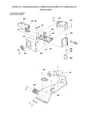
FAULT FINDING<strong>Heronhill</strong> - for all your <strong>Air</strong>king requirementsCONDITION POSSIBLE CAUSE ACTIONAIndoor fan motor will not runNo electric supply at socket or switched fuse Check fuse rating <strong>and</strong> replace if necessary.boxCheck for loose electrical connectionsUnit wiring faultCheck wiring <strong>and</strong> connectionsFan motor capacitor defectiveReplace if faultyFan motor defectiveReplace if faultyB Inadequate cooling or heating Dirty evaporator fins/filter Clean if blockedEvaporator motor not runningAs in section AFaulty thermostat or incorrectly set Replace if faultyCSystem runs for long periods <strong>and</strong>Unit underrated for conditioned areawill not cycleThermostat not operating correctlyCheck heat load against capacityCheck wiring, position of phial <strong>and</strong> operationD Noisy unit Worn motor bearing Replace motorCasing or piping vibrationCheck cause <strong>and</strong> rectifyLoose parts or mountingFind <strong>and</strong> tightenBent fan bladeReplace fanE Water leaking from unit Blocked drain Clear obstructionUnits with condensate pump No supply to pump or loose connection Secure the supplyFouled sensorClean sensorPumping slowlyCheck drain pipes; if clear, replace pumpPump windings shortedReplace pumpF Pump always runs Faulty sensor or pcb Replace sensor or pcbG No heating Controls not set for heating ResetUnit wiring faultCheck wiring <strong>and</strong> connectionsDirty evaporator fins/filterCleanFaulty thermostatCheck for signal; replace if faultyFaulty heater elementReplaceFaulty heater cutoutReplace, (check for short circuiting)No heaters/LPHW coil fittedFit electric heating elementsCOMPONENT IDENTIFICATION1 Suspension hook plate 19 Drip tray support bracket 37 Fresh air duct2 Suspension bracket 20 Cowl assembly 38 Coil assembly3 Panel end/bottom external electrics box 21 Plugs cover 39 Side panel4 Panel side external electrics box 22 Fan guard 40 Fan separation plate5 Panel end/top external electrics box 23 Fan <strong>and</strong> motor assembly 41 Condensate drain connector6 Terminal box cover 24 Capacitor bracket 42 Condensate pump pcb cover7 Terminals (screw - screw) 25 Capacitor 43 Access panel8 Relay 26 Drip tray support bracket 44 Condensate pump PCB9 Terminal block 12 way 27 Drip tray support bracket 45 Electrics blanking panel10 Top panel 28 Drip tray support bracket 46 Blanking panel11 Terminals end panel 29 Heater support bracket 47 Electrics box12 Access end panel 30 Heater retention plate 48 Electrics plate13 Access side panel 31 Thermal fuse 49 Fused terminal14 Condensate pump assembly 32 Heater element 50 Fuse 2A15 Coil support bracket 33 Heater cutout 51 Indoor PCB16 Motor lead cover 34 Cowl <strong>and</strong> fascia support pillar 52 Blanking panel17 Drip tray support bracket 35 Cowl, fascia <strong>and</strong> fresh air 53 Water level sensor18 Drip tray assembly 36 Fresh air end panel 54 Sensor bracket-33-Tel: 01823 665660 www.heronhill.co.uk Fax: 01823 665807
<strong>Heronhill</strong> - for all your <strong>Air</strong>king requirementsEXPLODED VIEW OF <strong>CWC</strong> L INDOOR UNIT (SIZE 185 SHOWN)-34-Tel: 01823 665660 www.heronhill.co.uk Fax: 01823 665807
<strong>Heronhill</strong> - for all your <strong>Air</strong>king requirementsEXPLODED VIEW OF THE FASCIA FRAME ASSEMBLY1 Fascia end moulding 8 Fascia end strengthener 15 Vane connector left h<strong>and</strong> 22 Bearing cap2 IR receiver cover 9 Fascia air deflector guide 16 Spider 23 Friction cap3 Fascia side moulding 10 <strong>Air</strong> deflector vane 17 Vane motor 24 Vane connector right h<strong>and</strong>4 Screw M4 x 25 11 Fascia side strengthener 18 Vane motor bracket 25 Auxiliary PCB5 Filter assembly 12 Vane end cap left h<strong>and</strong> 19 Double yoke6 Grille 13 Vane end cap right h<strong>and</strong> 20 Actuator spring7 IMI cover 14 Blanking cap insulation 21 Actuator arm-35-Tel: 01823 665660 www.heronhill.co.uk Fax: 01823 665807