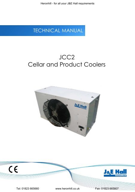
JCC2 Technical Manual (1) - Heronhill Air Conditioning Ltd
JCC2 Technical Manual (1) - Heronhill Air Conditioning Ltd
JCC2 Technical Manual (1) - Heronhill Air Conditioning Ltd

Create successful ePaper yourself
Turn your PDF publications into a flip-book with our unique Google optimized e-Paper software.
<strong>Heronhill</strong> - for all your J&E Hall requirementsSpecificationsCapacity dataModelCooling capacities in kW at 32°C ambient temperature4°C 6°C 8°C 10°C 12°C 12.7°C 14°C 16°C<strong>JCC2</strong> 25E 1.68 1.77 1.85 2.13 2.38 2.45 2.58 2.76<strong>JCC2</strong> 40E 2.96 3.13 3.36 3.70 3.93 4.05 4.17 4.28<strong>JCC2</strong> 50E 3.96 4.16 4.45 4.68 4.97 5.10 5.33 5.58<strong>JCC2</strong> 60E 4.92 5.14 5.34 5.71 5.92 6.13 6.52 6.70System dataCoolingUnit NoiseSystem Pipe Sizes Maximum Pipe RunModel Capacity<strong>Air</strong>flows LevelsKw Liquid Suction Length Rise m³/s dB(A)<strong>JCC2</strong> 25E 0.83 452.45 1/4" 1/2" 12m 5mJ5LC15C 0.45 30<strong>JCC2</strong> 40E 0.83 454.05 1/4" 1/2" 15m 8mJ5LC20C 0.61 32<strong>JCC2</strong> 50E 1.11 485.10 1/4" 5/8" 15m 8mJ5LC25C 0.69 32<strong>JCC2</strong> 60E 1.11 486.13 3/8" 5/8" 15m 8mJ5LC28C 0.63 34Notes:1) Db(A) Noise levels are sound pressure levels @ 10m free field2) Cooling capacities are nominal duties @ 12.7°C db / 10°C wb & 32°C ambient3) The pipe length must include the rise - the rise is not additional to the lengthIssue: 30.10.09 Page 4Tel: 01823 665660 www.heronhill.co.uk Fax: 01823 665807
<strong>Heronhill</strong> - for all your J&E Hall requirementsSpecificationsUnit dimensions & weightsModelUnit Dimensions (mm) Fixing Centres (mm) WeightsWidth Depth Height Width Depth Kg<strong>JCC2</strong> 25E 865 372* 489 745 n/a 30J5LC15C 700 250 540 441 278 33<strong>JCC2</strong> 40E 865 372* 489 745 n/a 33J5LC20C 855 328 651 603 362 59<strong>JCC2</strong> 50E 902 370* 545 824 n/a 36J5LC25C 855 328 750 603 362 62<strong>JCC2</strong> 60E 902 370* 545 824 n/a 38J5LC28C 855 328 750 603 362 68Notes:1) * Does not include fan motor depth - add 90mm2) Unit width does not include pipe services - add approximately 70mmElectrical data & requirementsOutdoor UnitIndoor Unit Mains Power Mains Interconnecting Suggested FuseModel Compressor Condenser Fan Evaporator Fan Supply Power To CableRatingLRA RRC Watts RRC Watts RRC V/Ph/Hz Amps<strong>JCC2</strong> 25E n/a n/a n/a n/a 70 0.65240/1/50 Indoor 3 Core16J5LC15C 24 5.1 35 0.3 n/a n/a<strong>JCC2</strong> 40E n/a n/a n/a n/a 70 0.65J5LC20C 27 6.5 64 0.5 n/a n/a240/1/50 Indoor 3 Core20<strong>JCC2</strong> 50E n/a n/a n/a n/a 110 0.82J5LC25C 32 7.5 75 0.6 n/a n/a240/1/50Indoor3 Core25<strong>JCC2</strong> 60E n/a n/a n/a n/a 110 0.82J5LC28C 63 11.3 75 0.6 n/a n/a240/1/50Indoor3 Core32Notes:1) LRA ~ Locked Rotor Amps2) RRC ~ Rated Running CurrentIssue: 30.10.09 Page 5Tel: 01823 665660 www.heronhill.co.uk Fax: 01823 665807
<strong>Heronhill</strong> - for all your J&E Hall requirementsHealth and SafetyImportant Note:Only a qualified refrigeration engineer, who is familiar with refrigeration systems andcomponents including all controls, should perform the installation and start-up of thesystem. To avoid potential injury, use care when working around coil surfaces or sharpedges of metal cabinets. All piping and electrical wiring should be installed inaccordance with all applicable codes, ordinances and local by-laws.General informationBefore Installation• Ensure the units received are the correct models for the intended application• Ensure the refrigerant, voltage and MWP are all suitable for the proposed application• Check there is no damage to the units• Check that the proposed equipment locations are suitable and provide adequate support for the weightof the unitsDuring Installation and subsequent maintenance• Installation and maintenance are to be performed only by qualified personnel who are familiar with localcodes and regulations, and experienced with this type of equipment• If lifting equipment is required, ensure that it is suitable for purpose, certificated and that the operativesare qualified to use it• Safe working methods are identified and operatives have suitable PPE• Ensure the working area has adequate ventilation during brazing procedures• The units contain moving machinery and electrical power hazards, which may cause severe injury ordeath. Disconnect and shut off power before installation or service of the equipment• Refrigerant release into the atmosphere is illegal. Proper evacuation, recovery, handling and leak testingprocedures must be observed at all times• Units must be earthed and no maintenance work should be attempted prior to disconnecting theelectrical supply• The electrical covers and fan guards must remain fitted at all times• Use of the units outside of the design conditions and the application for which the units were intendedmay be unsafe and be detrimental to the units, regardless of short or long term operation• The units are not designed to withstand loads or stresses from other equipment or personnel. Suchextraneous loads or stress may cause failure/leak/injuryIssue: 30.10.09 Page 6Tel: 01823 665660 www.heronhill.co.uk Fax: 01823 665807
<strong>Heronhill</strong> - for all your J&E Hall requirementsInstallationUnit location• In order to achieve maximum cooling capacity, the installation location for the condensing unit shouldbe carefully selected• Install the condensing unit in such a way so that hot air ejected by the condensing unit cannot be drawnin again (short circuit of hot discharge air). Allow sufficient space for maintenance around the unitX• Ensure that there is no obstruction to air flow into or out of the unit. Remove obstacles which block airintake or dischargeX• The location must be well ventilated, so the unit can draw in and distribute plenty of air thus lowering thecondensing temperature• To optimize the unit running conditions, the condenser coil must be cleaned at regular intervalsThe indoor units can be mounted directly to a wall or to the ceiling utilizing the fixing holes on the rear of theunit or on the top of the unit. No additional brackets are required. Position the indoor unit where the optimumairflow can be achieved. Avoid locating in corners or in alcoves which may restrict airflows. A minimum10mm rawlbolt type fixing is required with a large steel washer to bear the unit weight. It is important toensure that the wall/ceiling is able to withstand the unit weight and that all fixings are secure.Both indoor and outdoor units must be level in both directions.Issue: 30.10.09 Page 7Tel: 01823 665660 www.heronhill.co.uk Fax: 01823 665807
<strong>Heronhill</strong> - for all your J&E Hall requirementsInstallationInstallation clearances• The installation location should allow sufficient space for air flow and maintenance around the unitsOutdoorIndoor500mm500mm1500mm toany obstructionMinimum 1800mm fromfloor levelIssue: 30.10.09 Page 8Tel: 01823 665660 www.heronhill.co.uk Fax: 01823 665807
<strong>Heronhill</strong> - for all your J&E Hall requirementsInstallationField pipingImportant Note:Pipe sizes and maximum lengths/heights should be strictly as per the informationgiven on page 4. All local codes of practice must be observed in the installation ofrefrigerant pipingTo ensure satisfactory operation and performance, the following points should be notedfor field piping arrangements:• Pipework routes must be as simple and as short as possible• Avoid low points on pipework where oil can accumulate• Use only clean, dehydrated refrigeration grade copper tube with long radius bends• When brazing use only silver alloy rods• Run braze without over filling to ensure there is no leakage into the tube• To prevent oxidization, blow oxygen free nitrogen through pipework when brazing• Protect the casing of the unit when brazing connections• Install insulation with a minimum wall thickness of 3/8” on both liquid and suction lines• Adequately support all pipe work at a maximum of 2 metre intervalsUse of incorrect pipe sizes can affect system pressures/temperatures and gas velocity forproper oil return.Important Note:One of the main factors affecting equipment reliability and compressor service life isrefrigeration circuit contamination. During installation, circuit contamination can becaused by:• Brazing & Welding Oxides• Filings & Particles from de-burring pipework• Brazing Flux• Moisture & <strong>Air</strong>Issue: 30.10.09 Page 9Tel: 01823 665660 www.heronhill.co.uk Fax: 01823 665807
<strong>Heronhill</strong> - for all your J&E Hall requirementsInstallationPressure testingBoth the indoor and outdoor units have been pressure tested in the factory prior todispatch. The indoor unit contains a holding charge of oxygen free nitrogen. The outdoorunit contains a charge of R410A refrigerant.Important Note:Do not open the service valves on the condensing unit until pressure testing andevacuation procedures have been carried out.Once the pipework installation is complete, it should be pressure tested prior to evacuation to test for leaks.A pressure leak test should be carried out using oxygen free nitrogen (OFN). NEVER USE OXYGEN FORPRESSURE TESTING SYSTEMS. A calibrated nitrogen pressure regulator must always be used. Before starting anypressure testing, ensure the area surrounding the system is safe, inform relevant personnel and fit warningsigns indicating high pressure testing. Also, use correct PPE as required.A simple procedure for testing is as follows:• Connect a pressure hose from the regulator to the schrader connection on the service port on thecondensing unit• Pressure system slowly up to 3 bar (45 psi) for 5 minutes and check for any signs of leakage• Increase pressure slowly up to 10 bar (150 psi) for 5 minutes and check for any signs of leakage• Increase pressure slowly up to 33 bar (500 psi) and check for any signs of leakage. Leave systemunder pressure for 24 hoursListen for any possible leaks and check all joints with bubble spray. If any leaks are discovered, releasepressure slowly from system until empty, repair leak and then restart pressure testing procedure. Neverattempt to repair a leak on a pressurized system.A strength test should also be incorporated according to local regulations.Once testing has been completed satisfactorily, release the pressure from the system gradually and safely toexternal atmosphere.Issue: 30.10.09 Page 10Tel: 01823 665660 www.heronhill.co.uk Fax: 01823 665807
<strong>Heronhill</strong> - for all your J&E Hall requirementsInstallationEvacuation & ChargingImportant Note:Moisture prevents proper functioning of the compressor and the refrigerationsystem. Ensure that a good quality vacuum pump is used to pull a minimumvacuum of 250 microns (0.33 mbar)Once pressure testing has been completed, the system can now be evacuated to remove air and anymoisture from the piping. This can be done as follows:• Ensure any nitrogen charge is safely released from the system• Connect a gauge manifold to the schrader connection on the service valve on the condensing unit• Connect a vacuum pump and vacuum gauge to the system• Evacuate the system until vacuum is below 250 microns (0.33 mbar)Note: A triple evacuation procedure is recommended for all new systems or where moisture is suspectedOnce the system is isolated and the vacuum pump is switched off, any rise in pressure indicates that eitherthere may be a leak in the system or moisture is still present. In this case, recheck the system for leaks, repairas necessary, and then restart the evacuation procedure. Once completed satisfactorily, the vacuum pumpand vacuum gauge can be removed.At this point, any additional refrigerant charge can be added to the system as required. Additionalrefrigerant must be charged in the liquid phase. Use calibrated weighing scales to add the correct amount.With the gauge manifold connected and closed, slowly open both of the service ports fully on thecondensing unit. This will release the refrigerant charge from the condensing unit into the system.Systems are precharged with refrigerant for pipe runs up to 7.6 metresAdditional refrigerant charge• <strong>JCC2</strong> 25E matched with J5LC15C – Pre Charged with 0.83kg R410aAdditional Charge – 20g per metre up to maximum permissible• <strong>JCC2</strong> 40E matched with J5LC20C – Pre Charged with 1.38kg R410aAdditional Charge – 20g per metre up to maximum permissible• <strong>JCC2</strong> 50E matched with J5LC25C – Pre Charged with 1.54kg R410aAdditional Charge – 20g per metre up to maximum permissible• <strong>JCC2</strong> 60E matched with J5LC28C – Pre Charged with 1.80kg R410aAdditional Charge – 50g per metre up to maximum permissibleIssue: 30.10.09 Page 11Tel: 01823 665660 www.heronhill.co.uk Fax: 01823 665807
<strong>Heronhill</strong> - for all your J&E Hall requirementsInstallationDrainageImportant Note:The evaporator drain pan fitting is supplied loose and must be fitted on site. It isattached to the indoor unit fan guard with a cable tie. Correct fitting is vital to ensureleak – free operation. The fitting does not require any sealant but a small amount ofsilicon sealant can be applied between the flared face of the fitting and the drip trayif so desired.The drain fitting is aluminium alloy with a 3/4” BSP male thread. A locknut is supplied to secure to the drainpan. The locknut only requires hand tightening and then pinching up with a spanner. Do not over tighten orthe threads may strip from the nut and also damage the tray. To fit the drain fitting, remove the drip tray(unscrew the seven screws that secure it), locate the fitting then refit the tray.A minimum suggested size of drain from the indoor unit is 20mm or 3/4”. This can be either copper or plastic.Flexible hose is not recommended as it can easily kink causing a blockage and water to back up in the unit.Issue: 30.10.09 Page 12Tel: 01823 665660 www.heronhill.co.uk Fax: 01823 665807
<strong>Heronhill</strong> - for all your J&E Hall requirementsInstallationElectricalImportant Note:The mains electrical supply to the indoor unit must be via a suitably rated isolator andmotor rated circuit breaker or fuse. There is no isolator fitted to either the indoor or theoutdoor unit. The rocker switch on the front of the indoor unit is for isolating the indoorfan and electronic controller only.Cable type and sizing must be selected for the particular application and the electricalinstallation should conform to the current local standards. All indoor and outdoor units areSingle Phase.• Cables to the indoor unit should be routed through the ‘U’ shaped cut-out in the bottom of theremovable air grille at the side of the unit and into the rear of the electric box• Cables to the outdoor unit should be routed under the plastic pipe / electrical connection cover onthe end of the unit• The interconnecting cable between the indoor and outdoor unit should be 3 core (2core + E)• Connect the mains supply and interconnecting cables as per the wiring diagrams on page 19Access to the electrical terminals and components on the indoor unit is via the two removable cover plateson the front of the unit. Removal of the upper cover plate gives access to the outdoor unit contactor.Removal of the lower cover plate gives access to the terminal block and fan capacitor, as well as theelectronic controller and rocker switch connections.Issue: 30.10.09 Page 13Tel: 01823 665660 www.heronhill.co.uk Fax: 01823 665807
<strong>Heronhill</strong> - for all your J&E Hall requirementsInstallationCommissioningImportant Note:Before starting the system, ensure that all electrical connections are correctlymade and tight, service ports are in the correct position and all covers and guardsare fitted.Switch on the power at the mains isolator and then switch on the rocker switch on the front of the indoor unit.Set the required operating temperature on the electronic controller and check the system parameters in thecontroller are as required (the controllers are pre-programmed in the factory to suggested settings)Run the system to the required temperature and check system pressures, gas charge and running currents ofmotors to ensure correct operation.Carry out a manual defrost (press the defrost button on the controller for more than 2 seconds) to ensure thedefrost period is adequate to clear any frost build up on the evaporator coilCarry out final leak test and ensure all covers are fitted and securing screws are tightenedLog all information along with system model and serial numbers for future referenceEnsure that the customer / responsible person is provided with basic operating instructions and whereelectrical isolators are situated in case of emergencyIssue: 30.10.09 Page 14Tel: 01823 665660 www.heronhill.co.uk Fax: 01823 665807
<strong>Heronhill</strong> - for all your J&E Hall requirementsService & MaintenanceImportant Note:Warning! – Disconnect the mains electrical supply before servicing oropening the unitsThe units are designed to give long life operation with minimum maintenance. However, they should beroutinely checked and the following service schedule is recommended under normal circumstances:1. Indoor and Outdoor units – Inspect at regular intervals• Check for refrigerant leaks on all joints and fittings• Inspect pipework for any damage• Ensure that no abnormal noise or vibration is detected during test run• Check all electrical connections2. Condenser & Evaporator Fan Motors & Blades – Clean and inspect at regular intervals• Check for abnormal noise, vibration and fan imbalance• Ensure that the fan motors are clean and spin freely• Check that the fan blades are clean and free from restriction• Note: The Fan Motors are pre-lubricated and factory sealed so no maintenance is necessary3. Condenser & Evaporator Coils – Clean and inspect at regular intervals.• Check and remove the dirt and debris between the fins using a soft brush and/or a suitable chemicalcoil cleaner then rinse with clean water• Check and remove any obstacles that may hinder the airflow through the coils• Repair any damage to fins and ensure any guards are fitted correctly• DO NOT USE HIGH PRESSURE WASHERS ON COILS – THEY DAMAGE THE FINS4. Power Supply – Inspect at regular intervals.• Check the running current and voltage for the units• Check the electrical wiring and tighten the wires onto the terminal blocks if necessaryIssue: 30.10.09 Page 15Tel: 01823 665660 www.heronhill.co.uk Fax: 01823 665807
<strong>Heronhill</strong> - for all your J&E Hall requirementsDrawingsIndoor unit dimensions (25E & 40E)Issue: 30.10.09 Page 16Tel: 01823 665660 www.heronhill.co.uk Fax: 01823 665807
<strong>Heronhill</strong> - for all your J&E Hall requirementsDrawingsIndoor unit dimensions (50E & 60E)Issue: 30.10.09 Page 17Tel: 01823 665660 www.heronhill.co.uk Fax: 01823 665807
<strong>Heronhill</strong> - for all your J&E Hall requirementsDrawingsOutdoor unit dimensionsMODEL A B C D E F G H I J K L M N O P Q R S TJ5LC15C 700 521 250 475 170 37 93 100 93 63 441 130 110 14 23 25 3 20 85 65J5LC20C 855 628 328 508 181 44 93 149 101 113 603 126 164 17 49 32 3 23 73 75J5LC25C 855 730 328 513 182 44 93 149 101 113 603 126 164 17 47 32 3 23 73 75J5LC28C 855 730 328 513 182 44 93 149 101 113 603 126 164 17 47 32 3 23 73 75Issue: 30.10.09 Page 18Tel: 01823 665660 www.heronhill.co.uk Fax: 01823 665807
<strong>Heronhill</strong> - for all your J&E Hall requirementsDrawingsElectrical wiring diagramsIndoorOutdoorCL CN E2Issue: 30.10.09 Page 19Tel: 01823 665660 www.heronhill.co.uk Fax: 01823 665807
<strong>Heronhill</strong> - for all your J&E Hall requirementsCertificationIssue: 30.10.09 Page 22Tel: 01823 665660 www.heronhill.co.uk Fax: 01823 665807
<strong>Heronhill</strong> - for all your J&E Hall requirementsJ & E Hall LimitedHansard GateWest MeadowsDerby, DE21 6JNEnglandTel: + 44 (0) 1332 253400Fax: + 44 (0) 1332 371061Email: helpline@jehall.co.ukWeb: www.jehall.comIssue: 30.10.09 Page 23Tel: 01823 665660 www.heronhill.co.uk Fax: 01823 665807
<strong>Heronhill</strong> - for all your J&E Hall requirementsTel: www.heronhill.co.uk01823 Fax: 01823 665660 665807