AIR CONDITIONER - Heronhill Air Conditioning Ltd
AIR CONDITIONER - Heronhill Air Conditioning Ltd
AIR CONDITIONER - Heronhill Air Conditioning Ltd

Create successful ePaper yourself
Turn your PDF publications into a flip-book with our unique Google optimized e-Paper software.
FILE NO. SVM-05020SERVICE MANUAL<strong>AIR</strong> <strong>CONDITIONER</strong>SPLIT WALL TYPERAS-13UKHP-ES4 / RAS-13UAH-ES4RAS-10UKHP-ES4 / RAS-10UAH-ES4RAS-13UKP-ES4 / RAS-13UA-ES4RAS-10UKP-ES4 / RAS-10UA-ES4RAS-07UKP-ES4 / RAS-07UA-ES4May 2005
1. SPECIFICATIONSCONTENTS2. CONSTRUCTION VIEWS2-1 Indoor Unit2-2 Outdoor Unit (RAS-13UAH-ES4, RAS-10UAH-ES4,RAS-13UA-ES4, RAS-10UA-ES4)2-3 Outdoor Unit (RAS-07UA-ES4)3. WIRING DIAGRAM3-1 RAS-13UKHP-ES4 / RAS-13UAH-ES43-2 RAS-10UKHP-ES4 / RAS-10UAH-ES43-3 RAS-13UKP-ES4 / RAS-13UA-ES43-4 RAS-10UKP-ES4 / RAS-10UA-ES43-5 RAS-07UKP-ES4 / RAS-07UA-ES44. SPECIFICATION OF ELECTRICAL PARTS4-1 Indoor Unit (RAS-13UKHP-ES4 RAS-10UKHP-ES4)4-2 Outdoor Unit (RAS-13UAH-ES4)4-3 Outdoor Unit (RAS-13UA-ES4)4-4 Outdoor Unit (RAS-10UAH-ES4)4-5 Indoor Unit (RAS-13UKP-ES4, RAS-10UKP-ES4,RAS-07UKP-ES4)4-6 Outdoor Unit (RAS-10UA-ES4)4-7 Outdoor Unit (RAS-07UA-ES4)5. REFRIGERATION CYCLE DIAGRAM5-1 RAS-13UKHP-ES4 / RAS-13UAH-ES45-2 RAS-10UKHP-ES4 / RAS-10UAH-ES45-3 RAS-13UKP-ES4 / RAS-13UA-ES45-4 RAS-10UKP-ES4 / RAS-10UA-ES45-5 RAS-07UKP-ES4 / RAS-07UA-ES46. CONTROL BLOCK DIAGRAM6-1 RAS-13UKHP-ES4 / RAS-13UAH-ES4RAS-10UKHP-ES4 / RAS-10UAH-ES46-2 RAS-13UKP-ES4 / RAS-13UA-ES4RAS-10UKP-ES4 / RAS-10UA-ES4RAS-07UKP-ES4 / RAS-07UA-ES47.OPERATION DESCRIPTION7-1 Outline of <strong>Air</strong> Conditioner Control7-2 Description of Operation Circuit7-3 Hi POWER Mode7-4 High-Temperature Limit Control7-5 Low-Temperature Limit Control7-6 Defrost Operation7-7 Current Limit Control7-8 Auto Restart Function7-9 Filter Check Lamp7-10 Self-Cleaning function7-11 QUIET Mode7-12 COMFORT SLEEP mode− 1 −FILE NO. SVM-05020
8. INSTALLATION PROCEDURE8-1 Safety Cautions8-2 Installation Diagram of Indoor and Outdoor Units8-3 Installation8-4 Indoor Unit8-5 Outdoor Unit8-6 How to Set Remote Control Selector Switch8-7 Others9. TROUBLESHOOTING CHART9-1 Troubleshooting Procedure9-2 Basic Check Items9-3 Primary Judgement9-4 Self-Diagnosis by Remote Control (Check Code)9-5 Troubleshooting Flowcharts9-6 Troubleshooting for Remote Control (Including The Indoor P.C. Board)10. PARTS REPLACEMENT10-1 Indoor Unit10-2 Outdoor Unit11. EXPLODED VIEWS AND PARTS LIST11-1 Indoor Unit (E-Parts Assy) (For Heat pump model)11-2 Indoor Unit (E-Parts Assy) (For Cooling model)11-3 Indoor Unit11-4 Outdoor Unit (RAS-13UAH-ES4)11-5 Outdoor Unit (RAS-10UAH-ES4)11-6 Outdoor Unit (RAS-13UA-ES4)11-7 Outdoor Unit (RAS-10UA-ES4)11-8 Outdoor Unit (RAS-07UA-ES4)FILE NO. SVM-05020• This air conditioner is charged withHFC (R410A) that doesn't deplete theOzone layer.• This air conditioner requires specialinstallation for the refrigerant R410A.− 2 −
1. SPECIFICATIONSFILE NO. SVM-05020MODEL RAS-13UKHP-ES4 RAS-13UKP-ES4RAS-13UAH-ES4RAS-13UA-ES4ITEM Cooling Heating CoolingCapacity220V 240V 220V 240V 220V 240VkW 3.74 3.82 4.32 4.40 3.90 3.95Phase1∅ Power source V 220 − 240Hz 50Power consumption kW 1.15 1.19 1.18 1.22 1.19 1.23Power factor % 98 96 98 96 98 97Running Indoor A 0.15current Outdoor A 5.20 5.00 5.35 5.15 5.35 5.15Starting current A 30 29Moisture removal lit/h 2.0NoiseRefrigerantRefrigerant controlIndoor (H/M/L) dB 41/35/31Outdoor (220-240V) dB 49 51 49 51 49 50Name of refrigerantRated amountGas side sizeConnection typeFlare connectionLiquid side size mm ∅6.35Interconnection Connection typepipeMaximum length(One way)Maximum heightdifferenceFlare connectionINDOOR UNIT RAS-13UKHP-ES4 RAS-13UKP-ES415* 1Height mm 275Dimensions Width mm 790Depth mm 208Net weight kg 10Evaporator typeIndoor fan typeFinned tubeCross flow fanHigh fan m 3 /h 630 650 630<strong>Air</strong> volume Medium fan m 3 /h 520 550 520Low fan m 3 /h 430 490 430Fan motor output W 20<strong>Air</strong> filterHoneycomb woven filter with PP frameOUTDOOR UNIT RAS-13UAH-ES4 RAS-13UA-ES4Height mm 550Dimensions Width mm 780Depth mm 270Net weight kg 4038Condenser typeOutdoor fan typeFinned tubePropeller fan<strong>Air</strong>flow volume m 3 /h 2120 2200 2120 2200 2030 2150Fan motor output W 42CompressorSafety deviceLouver typeModelR410Akg 0.95mmmCapillary tube∅ 12.7m 6PA150X2C-4FTOutput W 1100Fuse, Overload relayAutomatic louverUsable outdoor temperature range °C 15 ~ 43 −10 ~ 24 15 ~ 4330− 3 −
FILE NO. SVM-05020MODEL RAS-10UKHP-ES4 RAS-10UKP-ES4RAS-10UAH-ES4RAS-10UA-ES4ITEM Cooling Heating CoolingCapacity220V 240V 220V 240V 220V 240VkW 2.73 2.73 2.92 2.96 2.73 2.73Phase1∅ Power source V 220 − 240Hz 50Power consumption kW 0.83 0.85 0.79 0.82 0.83 0.85Power factor % 98 97 97 96 98 97Running Indoor A 0.15current Outdoor A 3.71 3.50 3.55 3.40 3.71 3.50Starting current A 18Moisture removal lit/h 1.2NoiseRefrigerantRefrigerant controlIndoor (H/M/L) dB 39/33/26Outdoor (220-240V) dB 47 49 47 49 46 47Name of refrigerantR410ARated amount kg 0.79 0.70Capillary tubeGas side size mm ∅ 9.52Connection typeFlare connectionLiquid side size mm ∅ 6.35Interconnection Connection typepipeMaximum length(One way)Maximum heightdifferenceFlare connectionm 10* 1INDOOR UNIT RAS-10UKHP-ES4 RAS-10UKP-ES4Height mm 275Dimensions Width mm 790Depth mm 208Net weight kg 10Evaporator typeIndoor fan typeFinned tubeCross flow fanHigh fan m 3 /h 570 610 610<strong>Air</strong> volume Medium fan m 3 /h 460 520 460Low fan m 3 /h 340 400 340Fan motor output W 20<strong>Air</strong> filterHoneycomb woven filter with PP frameOUTDOOR UNIT RAS-10UAH-ES4 RAS-10UA-ES4Height mm 550Dimensions Width mm 780Depth mm 270Net weight kg 32 30Condenser typeOutdoor fan typeFinned tubePropeller fan<strong>Air</strong>flow volume m 3 /h 2030 2150 2030 2150 1740 1850Fan motor output W 30 20CompressorSafety deviceLouver typeModelm 5Output W 750PA108X1C-4FZDNFuse, Overload relayAutomatic louverUsable outdoor temperature range °C 15 ~ 43 −10 ~ 24 15 ~ 43− 4 −
FILE NO. SVM-05020ITEMCapacityMODEL220VRAS-07UKP-ES4RAS-07UA-ES4Cooling240VkW 2.23 2.27PhasePower source V 220 − 2401∅Hz 50Power consumption kW 0.68 0.70Power factor % 98 96Running Indoor A 0.15current Outdoor A 3.00 2.90Starting current A 13Moisture removal lit/h 0.8NoiseRefrigerantRefrigerant controlIndoor (H/M/L) dB 38/32/26Outdoor (220-240V) dB 44 45Name of refrigerantR410ARated amount kg 0.63Capillary tubeGas side size mm ∅9.52Connection typeFlare connectionLiquid side size mm ∅6.35Interconnection Connection typepipeINDOOR UNITMaximum length(One way)Maximum heightdifferenceFlare connectionm10* 1RAS-07UKP-ES4Height mm 275Dimensions Width mm 790Depth mm 208Net weight kg 10Evaporator typeIndoor fan typeFinned tubeCross flow fanHigh fan m 3 /h 570<strong>Air</strong> volume Medium fan m 3 /h 460Low fan m 3 /h 340Fan motor output W 20<strong>Air</strong> filterOUTDOOR UNITHoneycomb woven filter with PP frameRAS-07UA-ES4Height mm 530Dimensions Width mm 660Depth mm 240Net weight kg 27Condenser typeOutdoor fan typeFinned tubePropeller fan<strong>Air</strong>flow volume m 3 /h 1420 1520Fan motor output W 30CompressorSafety deviceLouver typeModelmPA82X1C-4DZDNOutput W 605Fuse, Overload relayAutomatic louverUsable outdoor temperature range °C 15 ~ 435− 5 −
FILE NO. SVM-05020Note : 1• Capacity is based on the following temperature conditions.TemperatureConditionCoolingJIS B8615-1HeatingIndoor unit inlet air temperatureOutdoor unit inlet air temperature(DB) 27°C 20°C(WB) 19°C 15°C(DB) 35°C 7°C(WB) 24°C 6°CNote : 2*1 No need to charge extra refrigerant.− 6 −
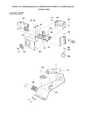
FILE NO. SVM-050202-2. Outdoor Unit (RAS-13UAH-ES4, RAS-10UAH-ES4,RAS-13UA-ES4, RAS-10UA-ES4)A∅ 6 HoleA Detail Drawing (Back Leg)3103025236600R15R5.531030232.5115 125102B Detail Drawing (Front Leg)310302∅ 6 Hole∅ 11x14 Hole3652R15∅ 30 Drain outlet∅ 436FAN GUARD2-∅ 11x14 Hole(For ∅ 8-∅ 10 anchor bolt)BCOVER PV530Z265270600 90780 62310330Electricalpart cover1207554Liquid side(Flare ∅ 6.35)Gas side(Flare ∅ 9.52)10 SeriesGas side(Flare ∅ 12.7)13 SeriesB or more325Z ViewInstallation dimension600<strong>Air</strong> inletService port600 or more 13 Series 10 SeriesA 600 mm 400 mm100 or more<strong>Air</strong> outletA or moreB 100 mm 45 mm4x∅ 11 Long holes (For∅ 8-∅ 10 anchor bolt)− 8 −
2. CONSTRUCTION VIEWSFILE NO. SVM-050202-1. Indoor UnitFront panelBack body<strong>Air</strong> inlet <strong>Air</strong> filter Heat exchanger790 2086 60275Knock out system<strong>Air</strong> outlet486 60Knock out system40486453120 59080HangerDrain hose (0.54m)45Hanger320620235 235215 215Minimumdistanceto ceiling65 or moreHangerConnecting pipe (0.43m)(Flare ∅6.35)Connecting pipe (0.33m)(For 13 series ; Flare ∅12.7For 07, 10 series ; Flare ∅ 9.52)For stud bolt(∅ 8~∅10)For stud bolt (∅6)2645275Minimumdistanceto ceiling170 or moreMinimumdistanceto ceiling170 or more190160HangerHanger3257 1890150 160 160150 90Installation plate outlineCenter lineWireless remote control− 7 −
FILE NO. SVM-050202-3. Outdoor Unit (RAS-07UA-ES4)A97A Detail Drawing (Back Leg)∅6 Hole273.52656605036 R 15R 5.5273.559.5∅25Drain outletBB Detail Drawing (Front Leg)273.5265∅6 Hole∅11x14 Hole3650660R 15Fan guard2-∅11x14 hole(for ∅8-∅10 anchor bolt)Cover PV∅420Z530242500 97.5 (11)66056273.5 (pitch)297(12.5)1264854Liquid side(Flare ∅6.35)Gas side(Flare ∅9.52)Z ViewService portInstallation dimension600100 or more<strong>Air</strong> inlet600 or more325100 or more 600 or more<strong>Air</strong> outlet4x∅11x14 Long holes (for ∅8-∅10 anchor bolt)− 9 −
FILE NO. SVM-050203-2. RAS-10UKHP-ES4 / RAS-10UAH-ES4LNBRWBLUGRN & YELSINGLE PHASE220-240V 50HzBLKP0413T02C.T.13CN27CN0311BLKSG01DSA22BLKR22VARISTOR3BLK 4THERMOPNKRY03SENSOR (TA)11PNK22RY0173°CTHERMAL FUSECN04T6.3A 250VACFUSE F01RY04CR01CN01 CR021 21 2HEAT EXCHANGERSENSOR (TC)BLKBLKLouverMotorR21VARISTORYELC01YELYELCN07YEL5 4 3 2 15 4 3 2 1MAIN P.C. BOARDWP-003150°CWHIL01CN25DC5VBLU1 12 23 34 45 56 6INFRARED RAYS RECEIVEAND INDICATION PARTS1 2 3 4 5 6 7 8 9 10 111 2 3 4 5 6 7 8 9 10 11C02CR03BLUCN10BLKBLUGRYYELBRWREDWHIIC03C15BLU55BLUR26BLUR319BLUR25R27BLU3 13 1BLUDB01BLUWHI1 2 3 4 5 6 7 8 9 10 111 2 3 4 5 6 7 8 9 10 11VoltageRegulatorMicroPowerModuleDC12VCN14+C63CN111 2 31 2 3AC FAN MOTORINDOORTERMINALBLOCKBLKWHIREDBLU1 2 3 4GRN&YELINDOOROUTDOORTERMINALBLOCK 3BLK1(L)2(N)4BLK BLKCHASSISOUTDOORSOLENOID COILOVERLOAD RELAYREDCAPACITORBLKREDREDWHI BLKCOMPRESSORFANMOTORPNKWHICAPACITORAWLF-240-30AHF-240-30BDetails A− 11 −
3-3. RAS-13UKP-ES4 / RAS-13UA-ES4FILE NO. SVM-05020CN25Infrared rays receiverand indication parts.1 2 3 4 5 6 7 8 9 10 111 2 3 4 5 6 7 8 9 10 11TRANS (TT-10)Heat ExchangerSensor (TC)Thermo Sensor (TA)LNSingle Phase220V~, 50HzGRN&YELBRW (L)BLU (N)CN14CN011 12 2CN031 12 2BLUBLUBLUBLUBLUBLUBLUBLUBLUBLUWHI1 2 3 4 5 6 7 8 9 10 111 2 3 4 5 6 7 8 9 10 11F01T6.3 A250 VACR213C15RY01R22L0142 13SG01DSA4C01BLKP04RED11DB50IC03WHI33 CN05C50+R46BLURegulatorcircuitR4711R4833GRYCN06D38MCC-920DC 12 VDC 5 VCR03C58CN071 1WHI2 2YEL3 3YEL4 4YEL5 5YELCN11YEL1 12 2GRYBRW3 3CN105 53 31 1WHIBLKRED1 12 23 34 45 5Louver motor150 C1 12 23 34 45 56 6Indoor FAN motorCN31CN041 21 2TEMP FUSEINDOORTERMINALBLOCKBLKWHI1 2GRN&YELPNKINDOORPNK73 COUTDOORTERMINALBLOCKOUTDOOR1(L)2(N)CHASSISBLK BLK REDREDCAPACITORCAPACITORFAN MOTORREDWHIACOMPRESSORPNKWHIHF-240-30BDetails AWLF-240-30A− 12 −
3-4. RAS-10UKP-ES4 / RAS-10UA-ES4FILE NO. SVM-05020CN25Infrared rays receiverand indication parts.1 2 3 4 5 6 7 8 9 10 111 2 3 4 5 6 7 8 9 10 11TRANS (TT-10)Heat ExchangerSensor (TC)Thermo Sensor (TA)LNSingle Phase220V~, 50HzGRN&YELBRW (L)BLU (N)CN14CN011 12 2CN031 12 2BLUBLUBLUBLUBLUBLUBLUBLUBLUBLUWHI1 2 3 4 5 6 7 8 9 10 111 2 3 4 5 6 7 8 9 10 11F01T6.3 A250 VACR213C15RY01R22L0142 13SG01DSA4C01BLKP04RED11DB50IC03WHI33 CN05C50+R46BLURegulatorcircuitR4711R4833GRYCN06D38MCC-920DC 12 VDC 5 VCR03C58CN071 1WHI2 2YEL3 3YEL4 4YEL5 5YELCN11YEL1 12 2GRYBRW3 3CN105 53 31 1WHIBLKRED1 12 23 34 45 5Louver motor150 C1 12 23 34 45 56 6Indoor FAN motorCN31CN041 21 2TEMP FUSEINDOORTERMINALBLOCKBLKWHI1 2GRN&YELPNKINDOORPNK73 COUTDOORTERMINALBLOCKOUTDOOR1(L) 2(N) CHASSISBLKBLKREDREDCAPACITORCAPACITORFAN MOTORREDWHIOVERLOAD RELAYCOMPRESSORREDWHI− 13 −
3-5. RAS-07UKP-ES4 / RAS-07UA-ES4FILE NO. SVM-05020CN25Infrared rays receiverand indication parts.1 2 3 4 5 6 7 8 9 10 111 2 3 4 5 6 7 8 9 10 11TRANS (TT-10)Heat ExchangerSensor (TC)Thermo Sensor (TA)LNSingle Phase220V~, 50HzGRN&YELBRW (L)BLU (N)CN14CN011 12 2CN031 12 2BLUBLUBLUBLUBLUBLUBLUBLUBLUBLUWHI1 2 3 4 5 6 7 8 9 10 111 2 3 4 5 6 7 8 9 10 11F01T6.3 A250 VACR213C15RY01R22L0142 13SG01DSA4C01BLKP04RED11DB50IC03WHI33 CN05C50+R46BLURegulatorcircuitR4711R4833GRYCN06D38MCC-920DC 12 VDC 5 VCR03C58CN071 1WHI2 2YEL3 3YEL4 4YEL5 5YELCN11YEL1 12 2GRYBRW3 3CN105 53 31 1WHIBLKRED1 12 23 34 45 5Louver motor150 C1 12 23 34 45 56 6Indoor FAN motorCN31CN041 21 2TEMP FUSEINDOORTERMINALBLOCKBLKWHI1 2GRN&YELPNKINDOORPNK73 COUTDOORTERMINALBLOCKOUTDOOR1(L)2(N)CHASSISBLK BLK REDREDCAPACITORCAPACITORFAN MOTORREDWHIAOVERLOAD RELAYCOMPRESSORPNKWHIHF-240-30BWLF-240-30ADetails A− 14 −
3. WIRING DIAGRAMFILE NO. SVM-050203-1. RAS-13UKHP-ES4 / RAS-13UAH-ES4LNBRWBLUGRN & YELSINGLE PHASE220-240V 50HzBLKP0413T02C.T.13CN27CN0311BLKSG01DSA22BLKR22VARISTOR3BLK 4THERMOPNKRY03SENSOR (TA)11PNK22RY0173°CTHERMAL FUSECN04T6.3A 250VACFUSE F01RY04CR01CN01 CR021 21 2HEAT EXCHANGERSENSOR (TC)BLKBLKLouverMotorR21VARISTORYELC01YELYELCN07YEL5 4 3 2 15 4 3 2 1MAIN P.C. BOARDWP-003150°CWHIL01CN25DC5VBLU1 12 23 34 45 56 6INFRARED RAYS RECEIVEAND INDICATION PARTS1 2 3 4 5 6 7 8 9 10 111 2 3 4 5 6 7 8 9 10 11C02CR03BLUCN10BLKBLUGRYYELBRWREDWHIIC03C15BLU55BLUBLUR319BLUBLU3 13 1BLUDB01BLUWHI1 2 3 4 5 6 7 8 9 10 111 2 3 4 5 6 7 8 9 10 11VoltageRegulatorR26R27MicroPowerModuleR25DC12VCN14+C63CN111 2 31 2 3AC FAN MOTORINDOORTERMINALBLOCKBLK1WHI2RED3BLU4GRN&YELINDOOROUTDOORTERMINALBLOCKBLK1(L)2(N)BLU3BLU4CHASSISOUTDOORSOLENOID COILREDCAPACITORREDREDWHIBLKCOMPRESSORFANMOTORPNKCAPACITORWHI− 10 −
4. SPECIFICATION OF ELECTRICAL PARTS4-1. Indoor Unit (RAS-13UKHP-ES4, RAS-10UKHP-ES4)FILE NO. SVM-05020No. Parts name Type Specifications1 Fan motor (for indoor) SKF-220-20-4A-1 AC Motor with 150°C thermo fuse2 Thermo sensor (TA-sensor) 10kΩ at 25°C3 Switching transformer (T01) SWT-474 Microcontroller unit (IC30) TMP87CM40AN5 Heat exchanger sensor(TC-sensor)6 Line filter (L01) LC*SS11V-062707 Bridge rectifier (DB01) D3SBA60 4A, 600V8 Capacitor (C02) KMH400VSSN47M22S 47µF, 400V9 Fuse (F01) TSCR6.3A T6.3A, 250VAC10 Varistor (R21, R22) 15G561K 560V11 Resistor (R01) RF-2TK5R6 5.6Ω, Ω 2W12 Louver motor MP24Z 12VDC10kΩ at 25°C27mH, 600mA13 Relay (Comp., RY01) DI12D1 Rating 20A/AC250V, 12VDC14 Relay (Fan, RY03) G5N-1A Rating 3A/AC250V, 12VDC15 Relay (Solenoide, RY04) G5N-1A Rating 3A/AC250V, 12VDC4-2. Outdoor Unit (RAS-13UAH-ES4)No. Parts name Type SpecificationsOutput (Rated) 1100W, 2poles, 1 phase, 220 − 240V, 50Hz1 Compressor PA150X2C-4FT Winding resistance (Ω) C-R C-S(at 20°C) 2.35 3.22Output (Rated) 42W, 6poles, 1 phase, 220 − 240V, 50Hz2 Fan motor (for outdoor) HF-240-42A or Winding resistance (Ω) Red-Black White-BlackWLF-240-42A(at 20°C) 176.2 or 188 290.5 or 28934Running capacitor(for fan motor)Running capacitor(for compressor)DS451155NPQBDS441306CPNKAC 450V, 1.5µFAC 440V, 30µFSolenoid coil5 (for 4-way valve) VHV-01AJ503C1 AC 220 − 240V, 50Hz(for Heat pump model)− 15 −
FILE NO. SVM-050204-3. Outdoor Unit (RAS-13UA-ES4)No. Parts name Type SpecificationsOutput (Rated) 1100W, 2poles, 1 phase, 220 − 240V, 50Hz1 Compressor PA150X2C-4FT Winding resistance (Ω) C-R C-S(at 20°C) 2.35 3.22Output (Rated) 30W, 6poles, 1 phase, 220 − 240V, 50Hz2 Fan motor (for outdoor)HF-240-30B orWinding resistance (Ω) Red-Black White-BlackWLF-240-30A(at 20°C) 245 or 237 388.3 or 3803Running capacitor(for fan motor)DS451155NPQB AC 450V, 1.5µF4Running capacitor(for compressor)DS441306CPNK AC 440V, 30µF4-4. Outdoor Unit (RAS-10UAH-ES4)No. Parts name Type SpecificationsOutput (Rated) 750W , 2poles, 1 phase, 220 − 240V, 50Hz1 Compressor PA108X1C-4FZDN Winding resistance (Ω) C-R C-S(at 20°C) 3.75 4.75Output (Rated) 30W, 6poles, 1 phase, 220 − 240V, 50Hz2 Fan motor (for outdoor) HF-240-30B or Winding resistance (Ω) Red-Black White-BlackWLF-240-30A(at 20°C) 245 or 237 388.3 or 380345Running capacitor(for fan motor)Running capacitor(for compressor)Solenoid coil(for 4-way valve)DS451155NPQBDS441256CPNLSQ-373AC 450V, 1.5µFAC 440V, 25µFAC 220 − 240V− 16 −
4-5. Indoor Unit (RAS-13UKP-ES4, RAS-10UKP-ES4, RAS-07UKP-ES4)FILE NO. SVM-05020No. Parts name Type Specifications1 Fan motor (for indoor) SKF-220-20-4A-1 AC Motor with 150°C thermo fuse2 Thermo sensor (TA-sensor) 10kΩat 25°C3 Transformer TT-104 Microcontroller unit (IC30) TMP87CM40AN5 Heat exchanger sensor(TC-sensor)10kΩat 25°C6 Line filter (L01) *SS11V-06270 27mH, 600mA7 Bridge rectifier (DB50) KBP06M/51 1.5A, 600V8 Capacitor (C50) PF1E222MNN1625 2200µF, 25V9 Fuse (F01) BET6.3A T6.3A, 250VAC10 Varistor (R21, R22) 15G561K320 560V11 L ouver motor MP24Z 12VDC12 Relay (Comp., RY01) DI1U Rating 25A/AC250V, 3~48VDC4-6. Outdoor Unit (RAS-10UA-ES4)No. Parts name Type SpecificationsOutput (Rated) 750W, 2poles, 1 phase, 220 − 240V, 50Hz1 Compressor PA108X1C-4FZDN Winding resistance (Ω) C-R C-S(at 20°C) 3.75 4.75Output (Rated) 20W, 6poles, 1 phase, 220 − 240V, 50HzHF-240-20B or2 Fan motor (for outdoor)Winding resistance (Ω) Red-Black White-BlackSKF-240-20B(at 20°C) 387.3 or 235.2 466.2 or 260.13Running capacitor(for fan motor)DS451155NPQB AC 450V, 1.5µF4Running capacitor(for compressor)DS441256CPNAL AC 440V, 25µF− 17 −
FILE NO. SVM-050204-7. Outdoor Unit (RAS-07UA-ES4)No. Parts name Type1Output (Rated) 605W, 2poles, 1 phase, 220 − 240V, 50HzC-RC-S4.84 4.40Output (Rated) 30W, 6poles, 1 phase, 220 − 240V, 50Hz2 Fan motor (for outdoor)HF-240-30B orWinding resistance (Ω) Red-Blac k White-BlackWLF-240-30A(at 20°C)245 or 237 388 or 38034CompressorRunning capacitor(for fan motor)Running capacitor(for compressor)PA82X1C-4DZDNDS451155NPQBWinding resistance (Ω)(at 20°C)AC 450V, 1.5µFDS441256CPNAL AC 440V, 25µFSpecifications– 18 –
5-1. RAS-13UKHP-ES4/ RAS-13UAH-ES45. REFRIGERATION CYCLE DIAGRAMFILE NO. SVM-05020CoolingIndoor unitHeat exchangerT10.39mHeating0.49m(Connecting pipe)(Connecting pipe)∅12.7 ∅6.35Cross flow fanO.D.:12.7mmPO.D.:6.35mmPacked valve(∅12.7)Packed valve(∅6.35)CoolingHeating4-way valveHeating Cooling CompressorPA150X2C-4FTAccumulatorCapillary tube∅1.5x1200lCapillary tube∅1.0x400lHeat exchangerCoolingHeatingPropeller fanOutdoor unitMark(RefrigerantR410A : 0.95 kg.)means check points of Gas Leak.50HzStandar dpressure P(MPaG)Surface temp. of heatexchang er inter changingpipe T1 (°C)Note :• Measure the heat exchanger temperature at the center of U-bend. (By means of TC sensor)*1 • During heating overload operation, a value for the high temperature limit control operation is included.− 19 −Fan speed(indoor)Ambient temp.conditions DB/WB(°C)IndoorOutdoorStandard 2.73 43.5 High 20/15 7/6Heating Overload*1 3.20 ~ 3.60 52.0 ~ 58.5 Low 27/− 24/18Low temperature 2.20 35.0 High 20/− −10/−10Standard 0.85 10.0 High 27/19 35/24Cooling Overload 0.99 14.0 High 32/23 43/26Low temperature 0.65 2.0 Low 21/15 21/15
5-2. RAS-10UKHP-ES4 / RAS-10UAH-ES4FILE NO. SVM-05020CoolingIndoor unitHeat exchangerT10.39m(Connecting pipe)∅9.52HeatingCross flow fan0.49m(Connecting pipe)∅6.35O.D.:9.52mmPO.D.:6.35mmPacked valve(∅9.52)Packed valve(∅6.35)CoolingHeating4-way valveCapillary tube∅1.5x1300lHeating Cooling CompressorPA108X1C-4FZDNAccumulatorCapillary tube∅1.5x1000lHeat exchangerCoolingHeatingPropeller fanOutdoor unitMark(RefrigerantR410A : 0.79 kg.)means check points of Gas Leak.50HzStandar dpressure P(MPaG)Surface temp. of heatexchanger inter changingpipe T1 (°C)Fan speed(indoor)Note :• Measure the heat exchanger temperature at the center of U-bend. (By means of TC sensor)Ambient temp.conditions DB/WB(°C)IndoorOutdoorStandard 2.22 37.0 High 20/15 7/6Heating Overload 3.43 54.0 Low 27/− 24/18Low temperature 2.10 35.0 High 20/− −10/−10Standard 0.95 11.0 High 27/19 35/24Cooling Overload 1.14 15.0 High 32/23 43/26Low temperature 0.85 5.0 Low 21/15 21/15− 20 −
5-3. RAS-13UKP-ES4 / RAS-13UA-ES4FILE NO. SVM-05020CoolingIndoor unitHeat exchangerT10.39m(Connecting pipe)∅12.7Cross flow fan0.49m(Connecting pipe)∅6.35O.D.:12.7mmPO.D.:6.35mmPacked valve(∅12.7)Packed valve(∅6.35)CoolingCooling CompressorPA150X2C-4FTAccumulatorCapillary tube∅1.7x600lHeat exchangerRefrigerantCoolingPropeller fanOutdoor unitMark(R410A : 0.95 kg.)means check points of Gas Leak.50HzStandar dpressure P(MPaG)Surface temp. of heatexchang er inter changingpipe T1 (°C)Fan speed(indoor)Note :•Measure the heat exchanger temperature at the center of U-bend. (By means of TC sensor)Ambient temp.conditions DB/WB(°C)IndoorOutdoorStandard 0.90 9.0 High 27/19 35/24Cooling Overload 1.12 13.0 High 32/23 43/26Low temperature 0.72 2.0 Low 21/15 21/15− 21 −
FILE NO. SVM-050205-4. RAS-10UKP-ES4 / RAS-10UA-ES4CoolingIndoor unitHeat exchangerT10.39m(Connecting pipe)∅9.52Cross flow fan0.49m(Connecting pipe)∅6.35O.D.:9.52mmPO.D.:6.35mmPacked valve(∅9.52)Packed valve(∅6.35)CoolingCooling CompressorPA108X1C-4FZDNCapillary tube∅1.5x1100lHeat exchangerRefrigerantCoolingPropeller fanOutdoor unitMark(R410A : 0.70 kg.)means check points of Gas Leak.50HzStandardpressure P(MPaG)Surface temp. of heatexchanger interchangingpipe T1 (°C)Fan speed(indoor)Ambient temp.conditions DB/WB(°C)IndoorOutdoorStandard 0.98 11.0 High 27/19 35/24Cooling Overload 1.10 15.0 High 32/23 43/26Low temperature 0.85 5.0 Low 21/15 21/15Note :•Measure the heat exchanger temperature at the center of U-bend. (By means of TC sensor)−22−
FILE NO. SVM-050205-5. RAS-07UKP-ES4 / RAS-07UA-ES4CoolingIndoor unitHeat exchangerT10.39m(Connecting pipe)∅9.52Cross flow fan0.49m(Connecting pipe)∅6.35O.D.:9.52mmPO.D.:6.35mmPacked valve(∅9.52)Packed valve(∅6.35)CoolingCooling CompressorPA82X1C-4DZDNCapillary tube∅1.2x550lHeat exchangerRefrigerantCoolingPropeller fanOutdoor unitMark(R-410A : 0.63 kg.)means check points of Gas Leak.50HzStandardpressure P(MPaG)Surface temp. of heatexchanger interchangingpipe T1 (°C)Fan speed(indoor)Ambient temp.conditions DB/WB(°C)IndoorOutdoorStandard 1.00 13.0 High 27/19 35/24Cooling Overload 1.14 18.0 High 32/23 43/26Low temperature 0.75 2.0 Low 21/15 21/15Note :• Measure the heat exchanger temperature at the center of U-bend. (By means of TC sensor)− 23 −
6. CONTROL BLOCK DIAGRAMFILE NO. SVM-050206-1. RAS-13UKHP-ES4 / RAS-13UAH-ES4, RAS-10UKHP-ES4 / RAS-10UAH-ES4Main Unit Control PanelM.C.U.Heat Exchange sensorFunctionsOperationDisplayThermo. Sensor•Louver ControlTimerDisplayCurrent Sensor(Compressor Current)Infrared Rays Signal ReciverInitiallizing CircuitClock FrequencyOscillator Circuit•3-minutes Delay at Restartfor Compressor•Motor Revolution Control•Processing(Temperature Processing)•TimerFilter SignDisplayHi PowerSign DisplayPRE DEF.Sign DisplayIndoor FanMotorPower SupplyCircuitCompressorON/OFFSignalOutdoor FanON/OFFSignal4-Way ValveON/OFFSignalLouverON/OFFSignalNoise FilterRelay Driver, Louver DriverLouverMotorRelayRY01RelayRY03RelayRY04220-240 V~, 50Hz Compressor Outdoor Fan Motor 4-Way ValveREMOTE CONTROLRemote ControlOperation ( )Infrared RaysOperation Mode SelectionAUTO, COOL, DRY, HEAT, FAN ONLYTemperature SettingFan Speed SelectionON TIMER SettingOFF TIMER SettingLouver Auto SwingLouver Direction SettingECOHi powerTIMER 1.3.5.9HCOMFORT SLEEPQUIET− 24 −
6-2. RAS-13UKP-ES4 / RAS-13UA-ES4,RAS-10UKP-ES4 / RAS-10UA-ES4,RAS-07UKP-ES4 / RAS-07UA-ES4FILE NO. SVM-05020Main Unit Control PanelM.C.U.Heat Exchange sensorFunctionsOperationDisplayThermo. Sensor•Louver ControlTimerDisplayInfrared Rays Signal ReciverInitiallizing CircuitClock FrequencyOscillator Circuit•3-minutes Delay at Restartfor Compressor•Motor Revolution Control•Processing(Temperature Processing)•TimerFilter SignDisplayHi PowerSign DisplayFan OnlySign DisplayIndoor FanMotorPower SupplyCircuitCompressorON/OFFSignalLouverON/OFFSignalNoise FilterRelay Driver, Louver DriverLouverMotorRelayRY01220-240 V~, 50Hz Compressor, Outdoor Fan MotorREMOTE CONTROLRemote ControlOperation ( )Operation Mode SelectionAUTO, COOL, DRY, FAN ONLYTemperature SettingFan Speed SelectionON TIMER SettingOFF TIMER SettingLouver Auto SwingLouver Direction SettingECOHi powerTIMER 1.3.5.9HCOMFORT SLEEPQUIETInfrared Rays− 25 −
7. OPERATION DESCRIPTIONFILE NO. SVM-050207-1. Outline of <strong>Air</strong> Conditioner ControlThis is a fixed capacity type air conditioner, which usesAC motor for an indoor fan. The AC motor drivecircuit is mounted in the indoor unit. And electricalparts which driving the compressor and the outdoorfan motor, are mounted in the outdoor unit.The air conditioner is controlled by the controllermounted in the indoor unit. The controller operates allcomponents based on the commands transmitted fromthe remote control and the feedback data of the sensoris as follow:• The temperature measurement at the air inlet ofthe indoor heat exchanger by the indoortemperature sensor•The temperature measurement at the indoorheat exchanger by the indoor heat exchangertemperature sensor• Indoor fan motor operation control• Louver motor control• LED display control• Outdoor fan motor operation control• 4-WAYS-VALVE operation control(Heat pump model only)• Compressor operation control• Receiving the information of the operationstatus and judging the information or theindication of errors7-1-1. Louver control(1) Vertical air flow louverPosition of veritcal air flow louver is automaticallycontrolled according to the operation mode.Besides, position of vertical air flow louver can bearbitrarily set by pressing [FIX] button.The louver position which is set by [FIX] button isstored in the microcontroller, and the louver isautomatically set at the stored position for the nextoperation.(2) SwingIf [SWING] button is pressed when the indoor unitis in operation, the vertical air flow louver startsswinging. When [SWING] button is pressed again,it stops swinging.7-1-2. Indoor fan control (AC Fan motor)(1) The indoor fan is operated by the stepless speedchange AC motor.(2) For air flow level, speed of the indoor fan motor iscontrolled in five steps (LOW, LOW + , MED, MED +and HIGH). If AUTO mode is selected, the fanmotor speed is automatically controlled by thedifference between the preset temperature andthe room temperature.Table 7-1-1LOW + =MED + =FAN TAPLOW+MED2MED+HIGH2Cooling UH H M L L- UL SLOPERATION Fan only H M L L-MODEDry M L L- UL SLHeat UH H M L L- UL SLRAS-07UK Seriesrpm 1350 1300 1200 1050 1000 950 900 800 750 700 650<strong>Air</strong> flow volume (m 3 /h) 650 630 570 490 460 430 400 340 310 280 250RAS-10UK Seriesrpm1350 1300 1250 1050 1000 950 900 800 750 700 650<strong>Air</strong> flow volume (m 3 /h) 650 630 610 490 460 430 400 340 310 280 250ModelRAS-10UKH SeriesRAS-13UK Seriesrpm<strong>Air</strong> flow volume (m 3 /h)rpm<strong>Air</strong> flow volume (m 3 /h)1300 1250 1200 1100 1000 900 800 750 700 650630 610 570 520 460 400 340 310 280 2501350 1300 1150 1100 1050 1000 950 900 850 800 750650 630 550 520 490 460 430 400 370 340 310700280RAS-13UKH Seriesrpm<strong>Air</strong> flow volume (m 3 /h)1350 1300 1150 1100 1050 1020 950 900 850 800 750650 630 550 520 490 470 430 400 370 340 310700280− 26 −
7-2. Description of Operation Circuit(1) When turning on the breaker, the operation lampblinks. This means that the power supply is on.(2) When pressing [ ] button on the remote control,receiving beep sounds from the indoor unit, andthe next operation is performed together withopening the vertical air flow louver.(3) Once the operation mode is set, it is memorized inthe microcontroller so that the previous operationcan be effected thereafter simply by pressing[ ] button.7-2-1. Fan only operation([MODE] button on the remote control is setto the fan only operation.)(1) When [FAN] button is set to AUTO, the indoor fanmotor operates as shown in Fig. 7-2-1. When[FAN] button is set to LOW, LOW + , MED, MED + orHIGH, the motor operates with a constant air flow.7-2-2. Cooling operation([MODE] button on the remote control is setto the cooling operation.)(1) The compressor, 4-way valve, outdoor fan andoperation display on the remote control arecontrolled as shown in Fig. 7-2-2.(Room temp.) - (Preset temp.)Presettemp.°C0.50FILE NO. SVM-05020ONONOFF OFF OFF ONCompressor4-way valveOutdoor fanOPERATIONdisplay(Room temp.) (Preset temp.)-Presettemp.°C+3+2.5+2+1.5+1+0.50(Preset temp.: 22 °C)NOTE :*1: The values marked with *1 are calculated andcontrolled by the difference in motor speedbetween M+ and L-.(2) The Hi POWER, ECO and COMFORT SLEEPoperation cannot be set.Fig. 7-2-1 Setting of air flow [FAN:AUTO]M+*1*1*1L-Fig. 7-2-2(2) When [FAN] button is set to AUTO, the indoor fanmotor operates as shown in Fig. 7-2-3. When[FAN] button is set to LOW, LOW + , MED, MED + orHIGH, the motor operates with a constant air flow.(Room temp.) − (Preset temp.)Presettemp.°C+3+2.5+2+1.5+1+0.50-0.5M+NOTE :*1: The values marked with *1 are calculated andcontrolled by the difference in motor speedbetween M+ and L-.*1*1*1L-Fig. 7-2-3 Setting of air flow [FAN:AUTO]- 27-
7-2-3. Dry operation([MODE] button on the remote control is setto the dry operation.)(1) The compressor, 4-way valve, outdoor fan andoperation display on the remote control arecontrolled as shown in Fig. 7-2-4.FILE NO. SVM-050207-2-4. Heating operation *Heat pump model only([MODE] button on the remote control is setto the heating operation.)(1) The compressor, 4-way valve, outdoor fan andoperation display on the remote control arecontrolled as shown in Fig. 7-2-6.(Room temp.) (Preset temp.)-Presettemp.°C+3+2+10ON:6min.OFF:4min.ON:5min.OFF:5min.OFFCompressorOFF4-way valveON:6min.OFF:4min.ON:5min.OFF:5min.OFFOutdoor fanONOPERATIONdisplayPresettemp.(Room temp.) (Preset temp.)-°C0-0.5OFF ON OFF ONONCompressor4-way valveONOutdoor fanOPERATIONdisplayFig. 7-2-4(2) The microcontroller turns the compressor on andoff at the regular intervals (4 to 6 minutes). Whilethe compressor is turning off, the indoor fan motoroperates in the SUPER LOW position.The pattern of operation depending on the relationbetween room temperature and presettemperatures is shown in Fig. 7-2-5.Room temp.Preset temp.+1Preset temp.CompressorOutdoor fanON ON ON ONOFF OFF OFFIndoor fan L *SL L SL L SL L*Super LowFig. 7-2-5Fig. 7-2-6(2) When [FAN] button is set to AUTO, the indoor fanmotor operates as shown in Fig. 7-2-7. When[FAN] button is set to LOW, LOW + , MED, MED + orHIGH, the motor operates with a constant air flow.Presettemp.(Room temp.) (Preset temp.)-°C0-0.5-1-1.5-2-5.0-5.5[FAN AUTO]*1, *2 : The values marked with *1 and *2 arecalculated and controlled by the difference inmotor speed between M+ and L.M +Fig. 7-2-7 Setting of air flow [FAN:AUTO]L*1*2H(3) [FAN] button on the remote control is set to AUTOonly.(4) The Hi POWER, ECO, COMFORT SLEEP andQUIET operations cannot be set.- 28 -
(3) The indoor heat exchanger restricts revolvingspeed of the fan motor to prevent a cold draft. Theupper limit of the revolving speed is shown inFig. 7-2-8 and Table 7-2-1.Indoor heat exchanger temperatureIndoor heat exchanger temperature*2*213UKH Series4241292834332120A+4A− 8 A+4A− 8*6 *510UKH Series46453231A+4A− 8°C34332120A+4A− 8*6 *5°CNOTES :*1: The fan stops for 2 minutes after thermostat-OFF.*2: A is 24°C when the preset temperature is 24°C ormore and A is the preset temperature when it isunder 24 °C.*3: SL means Super Low.AUTO*4: Calculated from difference in motor speedbetween SL and H.Fig. 7-2-8 Cold draft preventing control*4SL*3SL*1StopAUTO*4SL*3SL*1StopManual(One of 5 steps)L-H (Up toseting speed)Manual(One of 5 steps)L- H (Up toseting speed)*5 and *6:Table 7-2-1Fan *5 *6speed Starting period Stabilized periodAUTO ·· From 12 to 25 minutesUp until 12 minutespassed after startingthe unit· From 12 to 25 minutespassed after startingthe unit and roomtemperature is 3 °Clower than preset· temperature ·passed after startingthe unit and roomtemperature isbetween presettemperature and 3 °Clower than presettemperature 25 minutes or morepassed after startingthe unitManual · Room temperature · Room temperature(L - H) < Preset temperature- 4 °CPreset temperature-3.5 °C7-2-5. Automatic operation([MODE] button on the remote control is setto the automatic operation.)(1) One of 3 operations (Cooling, Fan only or Heating)is selected according to difference between thepreset temperature and the room temperature atwhich the automatic operation has started, asshown in Fig. 7-2-9. The Fan only operationcontinues until the room temperature reaches alevel at which another mode is selected.(2) Temporary AutoWhen the [TEMPORARY] button on the indoor unitis pushed, the preset temperature is fixed at 24 °Cand the indoor unit is controlled as shown inFig. 7-2-9.(Room temp.) - (Preset temp.)°C+40-1Cooling operationThe louver moves to the position sameas Hi POWER operation.Heating operationUKH SeriesFILE NO. SVM-05020Cooling operationFan only operationUK SeriesFig. 7-2-9- 29 -
7-3. Hi POWER Mode([Hi POWER] button on the remotecontrol is pressed.)When [Hi POWER] button is pressed while the indoorunit is in Auto, Cooling or Heating operation, HiPOWER mark is indicated on the display of the remotecontrol and the unit operates as follows.(1) Automatic operation· The indoor unit operates in according to thecurrent operation.(2) Cooling operation• The setting temperature drops 3°C.(The value of the setting temperature on theremote control does not change.)• If the room temperature is higher than thesetting temperature by 3.5°C or more, thehorizontal louver moves to the Hi POWERposition automatically. Then when the roomtemperature is 1°C less than the settingtemperature the horizontal louver returnsautomatically.• FAN speed : [AUTO]If the room temperature is higher than thesetting temperature by 3.5°C or more, the airconditioner operates at maximum airflow level.If the room temperature is higher than thesetting temperature by less than 3.5°C, the airconditioner operates at normal airflow level.• FAN speed : One of 5 levelsIf the room temperature is higher than thesetting temperature by 3.5°C or more, the airconditioner operates at higher consecutiveairflow level. If the room temperature is higherthan the setting temperature by less than 3.5°C,the air conditioner operates at normal airflowlevel.(3) Heating operation (UKH Series only)· The preset temperature increases 2°C,(The value of the preset temperature on theremote control does not change.)· The indoor unit operates in normal heatingmode except the preset temperature is higher(+2°C).(4) The Hi POWER mode can not be set in Dry or Fanonly operation.7-4. High-Temperature Limit Control*Heat pump model onlyThe microcontroller detects the indoor heat exchangertemperature to prevent pressure of a refrigerating cyclefrom increasing excessively.The compressor and outdoor fan motor are controlledas shown in Fig. 7-4-1.Compressor Outdoor fanOFFONONFig. 7-4-17-5. Low-Temperature Limit ControlThe microcontroller detects the indoor heat exchangertemperature to prevent the indoor heat exchanger fromfreezing.The compressor and outdoor fan motor are controlledas shown in Fig. 7-5-1 and 7-5-2.13UKH Series13UK Series(°C)6210UKH Series10UK Series07UK SeriesHeat exchangertemperature(°C)75OFFOFFONHeat exchangertemperatureFILE NO. SVM-05020Fig. 7-5-1Compressor Outdoor fanONHeat exchangertemp.(°C)605352Compressor Outdoor fanONLess than 2°C continuesfor 5 minutesOFFLess than 5 °C continuesfor 5 minutesOFFFig. 7-5-2- 30 -
7-6. Defrost Operation *Heat pump model onlyDuring the heating operation, the outdoor heatexchanger temperature goes down and sometimes it isfrozen.In this case, the air conditioner stops the heatingoperation and starts the defrost operation to melt ice.7-6-1. Condition to start the defrost operationThe defrost operation starts whichever belowconditions are satisfied.(1) When the cumulative compressor operating time islonger than 40 or 90 minutes and differencebetween the indoor heat exchanger temperatureand the room temperature is less than thespecified value. (This value is decided by themicroprocessor.) (Control example is shown inFig. 7-6-1. In case of B or C, the defrost operationstarts.)(2) When the current limit control or the hightemperature limit control is performed for total of90 minutes.Indoor heat exchanger temp- Room tempADBCCumulativecompressoroperating timeDEFROST LAMP :FILE NO. SVM-05020(1) The heating operation is performed for at least 90minutes.(2) The defrost operating time is 10 minutes.7-6-3. Ending condition at defrost operation(1) When the compressor current becomes 7.5A ormore during defrost operation, the defrostoperation stops and the heating operation restarts.(The current sensor detects the compressorcurrent.)(2) The defrost operation continues for at most6 minutes or 10 minutes.· During defrost operation, the PRE-DEF. lamp ison and the indoor and outdoor fans are off.· The compressor start protection timer is interlookedwith the PRE-DEF. lamp. So the PRE-DEF.Lamp is off (the fans stop) for about 3 minutesafter the [ ] button is turned on. Whenthe compressor is turned on, the PRE-DEF. lampcomes on. After the heat ex-changer is preheatedto about 24 °C or higher, the PRE-DEF. Lampgoes off, and the indoor fan starts.Fig. 7-6-1 (Indoor fan speed : M)7-6-2. Defrost operation time control(1) The heating operation is performed for at least40 minutes.(2) The maximum defrost operating time is 6 minutes.The defrost operating time for the 4th cycle is10 minutes. (When the outdoor temperature isvery low, however, the defrost operating time is10 minutes.)minutes40minutes40minutes40minutes40HeatingDefrostHeatingDefrostHeatingDefrostHeatingDefrostMax 6 minutes10 minutes1 cycleFig. 7-6-2- 31 -
7-7. Current Limit Control *Heat pump modelonlyThe microcontroller detects the input current so as toprevent it exceeds a specified value by means ofcontrolling the outdoor fan control as described in (1)and (2).FILE NO. SVM-05020(1) Current limit control (Cooling operation)Control is performed as shown below by detectingthe compressor operating current with a currentsensor (C.T).Input current13UKH Series / 10UKH Series13.5A / 19.2A I412.5A / 17.8A I3CompressorOutdoor fanMore than I4 continues for 3 secondsOFFMore than I3 continues for 5 secondsOFFONFig. 7-7-1(2) Current limit control (Heating operation)Control is performed as shown in Fig. 7-7-2Input current13UKH Series / 10UKH Series13.5A / 19.2A I412.5A / 17.8A I3CompressorOutdoor fanMore than I4 continues for 3 secondsOFFMore than I3 continues for 5 secondsOFF10A / 15.6AI2ONOFF9A / 15.0AI1ONFig. 7-7-2Remark :1. This function is available only for heat pump model (Cooling models have no a current sensor (C.T.)).2. For 10UKH Series, the value of currents shown on the diagram above are two times the actualoperating value. This is because the lead wire operated two times through the C.T.- 32 -
7-8. Auto Restart FunctionThe indoor unit is equipped with an automaticrestarting function which allows the unit to restartoperating with the set operating conditions in the eventof power supply being accidentally shut down. Theoperation will resume without warning three minutesafter power is restored.This function is not set to work when shipped from thefactory. Therefore it is necessary to set it to work.7-8-1. How to set auto restart functionFILE NO. SVM-05020To set the auto restart function, proceed as follows:The power supply to the unit must be on; the functionwill not set if the power is off.Push the [TEMPORARY] button located in the centerof the front panel continuously for three seconds.The unit receives the signal and beeps three times.The unit then restarts operating automatically in theevent of power supply being accidentally shut down.When the unit is on standby (Not operating)OperationMotionsPush [TEMPORARY] button for more The unit is on standby.than three seconds.¯The unit starts to operate.The green lamp is on.¯ After approx. three seconds,03SThe unit beeps three times The lamp changes fromand continues to operate.green to orange.[TEMPORARY] buttonIf the unit is not required to operate at this time, push [TEMPORARY]button once more or use the remote control to turn it off.When the unit is in operationOperationMotionsPush [TEMPORARY] button for more The unit is in operation. The green lamp is on.than three seconds.¯[TEMPORARY] button03SThe unit stops operating.¯The unit beeps three timesAfter approx. three seconds,The green lamp is turned off.If the unit is required to operate at this time, push [TEMPORARY]button once more or use the remote control to turn it on.···While this function is being set, if the unit is inoperation, the orange lamp is on.This function can not be set if the timer operationhas been selected.When the unit is turned on by this function, thelouver will not swing even though it was swingingautomatically before shutting down.·While the filter check lamp is on, the[TEMPORARY] button has the function of filterreset button.- 33 -
7-8-2. How to cancel auto restart functionTo cancel auto restart function, proceed as follows:Repeat the setting prodedure: the unit receives thesignal and beeps three times.The unit will be required to be turned on with theremote control after the main power supply is turnedoff.FILE NO. SVM-05020When the unit is on standby (Not operating)OperationMotionsPush [TEMPORARY] button for more The unit is on standby.than three seconds.¯The unit starts to operate.The orange lamp is on.¯ After approx. three seconds,03SThe unit beeps three times The lamp changes fromand continues ¯ to operate.orange to green.[TEMPORARY] buttonIf the unit is not required to operate at this time, push [TEMPORARY]button once more or use the remote control to turn it off.When the unit is in operationOperationMotionsPush [TEMPORARY] button for more The unit is in operation. The orange lamp is on.than three seconds.¯[TEMPORARY] button03SThe unit stops operating.¯The unit beeps three timesAfter approx. three seconds,The orange lamp is turned off.If the unit is required to operate at this time, push [TEMPORARY]button once more or use the remote control to turn it on.·While this function is being set, if the unit is inoperation, the orange lamp is on.7-8-3. Power failure during timer operationWhen the unit is in Timer operation, if it is turned offbecause of power failure, the timer operation iscancelled. Therefore, set the timer operation again.7-9. Filter Check LampWhen the elapsed time reaches 1000 hours, the filtercheck lamp indicates. After cleaning the filters, turn offthe filter check lamp.7-9-1. How to turn off filter check lampPush [TEMPORARY] button on the indoor unit.Note:If [TEMPORARY] button is pushed while the filtercheck lamp is not indicating, the indoor unit will startthe Automatic Operation.- 34-
7-10. Self-Cleaning functionFILE NO. SVM-05020Self-Cleaning function is designed to reduce humidity that causes mold to form inside the air conditioning unit.This advanced, efficient system reduces moisture in the coil. When air conditioner is turned off, the internal fanactivates and dries the moisture in the coil for 20 minutes, then it turns off automatically.Operation display ON OFF OFFFCU fanONrpm is depend on presetting.ONrpm is SL speed.OFFFCU louver OPEN CLOSE CLOSETimer displayON or OFFdepend on presetting of timer function.ONON or OFFdepend on presetting of timer function.CompressorON or OFFdepend on presetting per room temperature.OFFOFFCDU fanON or OFFdepend on presetting per room temperature.Cool mode or dry modeoperation more than 10 mins.OFFOFF8 8-Self-Cleaning modeOperation timeoperate 20 mins.Turn off by remote controller ortimer-off function.Automatically turn-off.• The Self-Cleaning function is set as default at ex-factory.• Self-Cleaning operation can stop manually by press [ ] button of the remote control two more time.7-10-1. How to cancel Self-Cleaning functionTo cancel the Self-Cleaning function, proceed asfollows:• Press [TEMPORARY] button one time or use remotecontrol to turn on air conditioner. The OPERATIONdisplay will show in orange color (When AUTO-RESTART is ON) or green color (When AUTO-RESTART is OFF).• Hold down the [TEMPORARY] button for more than20 seconds. (The air conditioner will stop suddenlywhen the [TEMPORARY] button is pressed but keepholding it continue. Then will beep 3 times in the first3 seconds but it is not related to Self-Cleaningfunction)• After holding about 20 seconds, the air conditionerwill beep 5 times without any blinking of display.• The Self-Cleaning Operation had been cancelled.Remarks• Per setting of Self-Cleaning function above, AUTO-RESTART function had been cancelled. To setAUTO-RESTART again, please follow item 7-8-1.7-10-2. How to set Self-Cleaning function.To set the Self-Cleaning function, proceed as follows.• Press [TEMPORARY] button one time or use remotecontrol to turn on air conditioner. The OPERATIONdisplay will show in orange color (When AUTO-RESET is ON) or green color (When AUTO-RESTART is OFF).• Hold down the [TEMPORARY] button for more than20 seconds. (The air conditioner will stop suddenlywhen the [TEMPORARY] button is pressed but keepholding it continue. Then will beep 3 times is the first3 seconds but it is not related to Self-Cleaningfunction)• After holding about 20 seconds, the air conditionerwill beep 5 times and OPERATION display blinks5 times.• The Self-Cleaning function had been set.Remarks• Per setting of Self-Cleaning function above, AUTO-RESTART function had been cancelled. To setAUTO-RESTART again, please follow item 7-8-1.– 35 –
FILE NO. SVM-050207-11. QUIET ModeQuiet mode is the system which, control therevolving speed of indoor fan to work constantlyat lower than speed L. In addition, noise level ofindoor unit is less than usual.When the [QUIET] button is pressed, the fan of theindoor unit will be restricted the revolving speed atspeed L - until the [QUIET] button is pressed onceagain (cancel Quiet mode).Remarks :1. Quiet mode is unable to work in dry mode.2. Quiet mode is appropriate to work with lesscooling load and less heating load condition.Because of the fan speed L- may cause notenough the cooling capacity or heating capacity.7-12. COMFORT SLEEP modeThe principles of comfort sleep mode are:• Quietness for more comfortable.• Save energy by changing room temperatureautomatically.• The air condition can shut down by itselfautomatically.Remarks:1. Comfort sleep mode will not operate in dry modeand fan only mode.2. Comfort sleep mode is appropriate to work with lesscooling load and less heating load condition.Because of the fan speed L- may cause not enoughthe cooling capacity or heating capacity.7-12-1. Cooling mode• The fan speed of indoor unit operates automatically,it relates with the compressor's operation.Compressor’s Operation Fan SpeedON L-OFFSL• The preset temperature will increase 1°C after theComfort sleep mode has operated for 1 hour andthe temperature will increase another 1°C after thecomfort sleep mode has operated for 2 hour. (Thevalue of the preset temperature on the remote controldoes not change.)• Press the [COMFORT SLEEP] button to choose theoperating hours. Repeat pressing to select the hours.(1hr, 3hr, 5hr or 9hr)• If the [COMFORT SLEEP] button is pressed againmeans cancel comfort sleep mode.7-12-2. Heating mode• The fan speed of indoor unit operates automatically,it relates with the compressor's operation.Compressor’s Operation Fan SpeedON L-OFFSL• The preset temperature will drop down 1°C after thecomfort sleep mode has operated for 1 hour and thetemperature will decrease another 1°C after thecomfort sleep mode has operated for 2 hour. (Thevalue of the preset temperature on the remote control.dose not change.)• Press the [COMFORT SLEEP] button to choose theoperating hours. Repeat pressing to select the hours.(1hr, 3hr, 5hr or 9 hr)• If the [COMFORT SLEEP] button is pressed againmeans cancel comfort sleep mode.- 36 -
8. INSTALLATION PROCEDUREFILE NO. SVM-050208-1. Safety CautionsFor general public usePower supply cord of parts of appliance for Outdoor use shall be at least polychloroprene sheathed flexiblecord (design H07 RN-F), or cord designation 245 IEC66.CAUTIONNew Refrigerant <strong>Air</strong> conditioner Installation• THIS <strong>AIR</strong> <strong>CONDITIONER</strong> USES THE NEW HFC REFRGERANT (R410A), WHICH DOES NOT DESTROYTHE OZONE LAYER.R410A refrigerant is apt to be affected by impurity such as water, oxidizing membranes, and oils because thepressure of R410A refrigerant is approx. 1.6 times of refrigerant R22. As well as the adoption of this newrefrigerant, refrigerating machine oil has also been changed. Therefore, during installation work, be sure thatwater, dust, former refrigerant, or refrigerating machine oil does not enter into the refrigerating cycle of anew-refrigerant air conditioner.To avoid mixing refrigerant and refrigerating machine oil, the sizes of charging port connecting sections onthe main unit are different from those for the conventional refrigerant, and different size tools are alsorequired. Accordingly, special tools are required for the new refrigerant (R410A) as shown below. Forconnecting pipes, use new and clean piping materials with high-pressure withstand capabilities, designed forR410A only, and ensure that water or dust does not enter. Moreover, do not use any existing piping as itspressure withstand may be insufficient, and may contain impurities.CAUTIONTo Disconnect the Appliance from the Main Power SupplyThis appliance must be connected to the main power supply by means of a circuit breaker or a switch with acontact separation of at least 3 mm.If this is not possible, a power supply plug with earth must be used. This plug must be easily accessible afterinstallation. The plug must be disconnected from the power supply socket in order to disconnect theappliance completely from the mains.− 37 −
DANGER− 38 −FILE NO. SVM-05020• FOR USE BY QUALIFIED PERSONS ONLY.• TURN OFF MAIN POWER SUPPLY BEFORE ATTEMPTING ANY ELECTRICAL WORK. MAKE SUREALL POWER SWITCHES ARE OFF. FAILURE TO DO SO MAY CAUSE ELECTRIC SHOCK.• CONNECT THE CONNECTING CABLE CORRECTLY. IF THE CONNECTING CABLE IS CONNECTEDWRONGLY, ELECTRIC PARTS MAY BE DAMAGED.• CHECK THE EARTH WIRE THAT IT IS NOT BROKEN OR DISCONNECTED BEFORE INSTALLATION.• DO NOT INSTALL NEAR CONCENTRATIONS OF COMBUSTIBLE GAS OR GAS VAPORS.FAILURE TO FOLLOW THIS INSTRUCTION CAN RESULT IN FIRE OR EXPLOSION.• TO PREVENT OVERHEATING THE INDOOR UNIT AND CAUSING A FIRE HAZARD, PLACE THE UNITWELL AWAY (MORE THAN 2 M) FROM HEAT SOURCES SUCH AS RADIATORS, HEATORS,FURNACE, STOVES, ETC.• WHEN MOVING THE <strong>AIR</strong>-<strong>CONDITIONER</strong> FOR INSTALLING IT IN ANOTHER PLACE AGAIN, BE VERYCAREFUL NOT TO GET THE SPECIFIED REFRIGERANT (R410A) WITH ANY OTHER GASEOUSBODY INTO THE REFRIGERATION CYCLE. IF <strong>AIR</strong> OR ANY OTHER GAS IS MIXED IN THEREFRIGERANT, THE GAS PRESSURE IN THE REFRIGERATION CYCLE BECOMES ABNORMALLYHIGH AND IT RESULTINGLY CAUSES BURST OF THE PIPE AND INJURIES ON PERSONS.• IN THE EVENT THAT THE REFRIGERANT GAS LEAKS OUT OF THE PIPE DURING THEINSTALLATION WORK, IMMEDIATELY LET FRESH <strong>AIR</strong> INTO THE ROOM. IF THE REFRIGERANT GASIS HEATED BY FIRE OR SOMETHING ELSE, IT CAUSES GENERATION OF POISONOUS GAS.WARNING• Never modify this unit by removing any of the safety guards or bypassing any of the safety interlockswitches.• Do not install in a place which cannot bear the weight of the unit.Personal injury and property damage can result if the unit falls.• Before doing the electrical work, attach an approved plug to the power supply cord.Also, make sure the equipment is properly earthed.• Appliance shall be installed in accordance with national wiring regulations.If you detect any damage, do not install the unit. Contact your TOSHIBA dealer immediately.CAUTION• Exposure of unit to water or other moisture before installation could result in electric shock.Do not store it in a wet basement or expose to rain or water.• After unpacking the unit, examine it carefully for possible damage.• Do not install in a place that can increase the vibration of the unit. Do not install in a place that can amplifythe noise level of the unit or where noise and discharged air might disturb neighbors.• To avoid personal injury, be careful when handling parts with sharp edges.• Please read this installation manual carefully before installing the unit. It contains further important instructionsfor proper installation.REQUIREMENT OF REPORT TO THE LOCAL POWER SUPPLIERPlease make absolutely sure that the installation of this appliance is reported to the local power supplierbefore installation. If you experience any problems, or if the installation is not accepted by the supplier, theservice agency will take adequate countermeasures.Remark per EMC Directive 89/336/EECTo prevent flicker impressions during the start of the compressor (technical process) following installationconditions do apply.1. The power connection for the air conditioner has to be done at the main power distribution. This distributionhas to be of an impedance.Normally the required impedance is reached at a 32A fusing point. <strong>Air</strong> conditioner fuse has to be 16A max.!2. No other equipment should be connected to this power line.3. For detailed installation acceptance, please contact your power supplier whether its restriction does applyfor products like washing machines, air conditioners or electrical ovens.4. For power details of the air conditioner, refer to the rating plate of the product.
8-2. Installation Diagram of Indoor and Outdoor UnitsFILE NO. SVM-05020Before installing thewireless remote control• With the remote control coveropen, load the batteries suppliedcorrectly, observing theirpolarity.170 mmor more65 mm or moreHook1 InstallationplateFor the rear left and leftpipingWall2 Wireless remote controlCover3 Batteries<strong>Air</strong> filterHook170 mmor moreInsert the cushion betweenthe indoor unit and wall,and tilt the indoor unit forbetter operation.(Attach to the front panel)ShieldpipeDo not allow the drain hoseto get slack.5Sasa Zeolite Plus filter6 Bio-enzyme & Gingko filter8 Pan head wood screwCut the piping holesloped slightly2 Wireless remotecontrolMake sure to run the drainhose sloped downward.13 series 07,10 seriesA 600 mm 400 mmB 100 mm 45 mm4 Remote control holderThe auxiliary piping can beconnected the left, rear left,rear right, right, bottom rightor bottom left.Right600 mm or moreB mm or moreVinyl tapeApply aftercarrying out adrainage test.SaddleRear rightRear leftBottom rightLeftBottom left100 mm or moreA mm or more600 mm or moreExtensiondrain hose(Not available,provided byinstallerInsulate the refrigerantpipes separately withinsulation, not together.6 mm thick heat resistingpolyethylene foam− 39 −
8-3. Installation8-3-1. Optional installation partsFILE NO. SVM-05020PartCodeABCParts nameRefrigerant pipingLiquid side : ∅6.35 mmGas side : ∅9.52 mm (07, 10 series)Gas side : ∅12.70 mm (13 series)Pipe insulating material(polyethylene foam, 6 mm thick)Putty, PVC tapesQ'tyOneeach1OneeachRAS-10, 13 SeriesRAS-07 Series115 mm32.5 mm30125 mm<strong>Air</strong> inlet500 mm<strong>Air</strong> inlet97 mm310 mm7 mm73 mm102 mm275 mm60 mm<strong>Air</strong> outlet600 mm90 mmDrain outlet<strong>Air</strong> outletDrain outletFig. 8-3-1• Secure the outdoor unit with fixing bolts and nuts if the unit is likely to be exposed to a strong wind.• Use ∅8 mm or ∅10 mm anchor bolts and nuts.• If it is necessary to drain the defrost water, attach 9 drain nipple and 10 cap water proof to thebottom plate of the outdoor unit before installing it.− 40−
FILE NO. SVM-050208-3-2. Accessory and installation partsPartNo.Part name (Q'ty)PartNo.Part name (Q'ty)PartNo.Part name (Q'ty)147Installation plate x 1Remote control holder x 1Mounting screw ∅4 x 25 s x 62Wireless remote control x 15Sasa Zeolite Plus filter x 18Pan head wood screw∅3.1 x 16 s x 2369Battery x 2Bio-enzyme & Gingko filter x 1Drain nipple* x 1 (For Heat pump model only)OthersNameOwner’s manualInstallation manual!Cap water proof* x 2(For Heat pump model only)The part marked with asterisk (*) is packaged with theoutdoor unit.− 41 −
8-3-3. Installation/Servicing toolsFILE NO. SVM-05020In the case of an air conditioner using R410A, in order to prevent any other refrigerant from being chargedaccidentally, the service port diameter of the outdoor unit control valve (3 way valve) has been changed. (1/2UNF 20 threads per inch)• In order to increase the pressure withstand strength of the refrigerant piping, flare processing diameter andsize of opposite side of flare nuts have been changed. (for copper pipes with nominal dimensions 1/2 and 5/8)New tools for R410A Applicable to R22 model ChangesGauge manifoldCharge hoseElectronic balancefor refrigerant chargingTorque wrench(nominal dia. 1/2, 5/8)Flare tool(clutch type)Gauge for projectionadjustmentVacuum pump adapterGas leakage detectorAs pressure is high, it is impossible to measure bymeans of conventional gauge. In order to preventany other refrigerant from being charged, eachport diameter has been changed.In order to increase pressure withstand strength,hose materials and port size have been changed(to 1/2 UNF 20 threads per inch).When purchasing a charge hose, be sure toconfirm the port size.As pressure is high and gasification speed is fast,it is difficult to read the indicated value by meansof a charging cylinder, as air bubbles occur.The size of opposing flare nuts has been increased.Incidentally, a common wrench is used for nominaldiameters 1/4 and 3/8.By increasing the clamp bar's receiving hole,strength of spring in the tool has been improved.Used when flare is made with a conventional flaretool.Connected to conventional vacuum pump. It isnecessary to use an adapter to prevent vacuumpump oil from flowing back to the charge hose.The charge hose connecting part has two ports:one for conventional refrigerant (7/16 UNF 20threads per inch) and one for R410A. If thevacuum pump mineral oil mixes with R410A,a sludge may occur and damage the equipment.Exclusive for HFC refrigerant.• Incidentally, the "refrigerant cylinder" comes with the refrigerant designation (R410A) and protector coating inthe U. S ARI specified rose color (ARI color code: PMS 507).• Also, the "charge port and packing for refrigerant cylinder" require 1/2 UNF 20 threads per inchcorresponding to the port size of the charge hose.– 42 –
FILE NO. SVM-050208-4. Indoor Unit8-4-1. Installation place• A place which provides the spaces around theindoor unit as shown in the above diagram.• A place where there is no obstacle near the air inletand outlet.• A place that allows easy installation of the piping tothe outdoor unit.• A place which allows the front panel to be opened.8-4-2. Cutting a hole and mounting installationplateWhen installing the refrigerant pipes from the rear.CAUTION• Direct sunlight to the indoor unit's wirelessreceiver should be avoided.• The microprocessor in the indoor unit should notbe too close to RF noise sources.(For details, see the owner's manual.)The center of the pipehole is above the arrow.Fig. 8-4-2100 mmPipehole∅65 mm• A place where there are no obstacles such as acurtain that may block the signal from the indoorunit.• Do not install the remote control in a place exposedto direct sunlight or close to a heating source, suchas a stove.• Keep the remote control at least 1 m apart from thenearest TV set or stereo equipment. (This isnecessary to prevent image disturbances or noiseinterference.)• The location of the remote control should bedetermined as shown below.1. After determining the pipe hole position on themounting plate (A), drill the pipe hole (∅65 mm) ata slight downward slant to the outdoor side.NOTE• When drilling a wall that contains a metal lath, wirelath or metal plate, be sure to use a pipe hole brimring sold separately.For installation of the indoor unit, use the paper patternon the back.Indoor unit75°(Side view)7 m(Top view)Indoor unit5 m45°45°5 m* 7 m17085Hook6282.5ReceptionrangeRemotecontrolReceptionrange* : Axial distanceRemote controlPipe holeHookThreadHookPipe hole1InstallationplateFig. 8-4-1Indoor unitWeight7 Mounting screwFig. 8-4-3− 43 −
FILE NO. SVM-050201. Securely fit the installation plate onto the wall byscrewing it in the upper and lower parts to hook upthe indoor unit.2. To mount the installation plate on a concrete wallwith anchor bolts, utilize the anchor bolt holes asillustrated in the above figure.3. Install the installation plate horizontally in the wall.CAUTIONWhen installing the installation plate with amounting screw, do not use the anchor bolt hole.Otherwise the unit may fall down and result inpersonal injury and property damage.Installation plate5 mm dia. holeClip anchor(local parts)CAUTIONFig. 8-4-4AnchorboltProjection15 mm or less7 Mountingscrew∅4 x 25sFailure to firmly install the unit may result inpersonal injury and property damage if the unit falls.8-4-3. Electrical work1. The supply voltage must be the same as the ratedvoltage of the air conditioner.2. Prepare the power source for exclusive use with theair conditioner.CAUTION• This appliance can be connected to the mains ineither of the following two ways.(1) Connection to fixed wiring:A switch or circuit breaker which disconnectsall poles and has a contact separation of atleast 3 mm must be incorporate in the fixedwiring. An approved circuit breaker orswitches must used.(2) Connection with power supply plug:Attach power supply plug with power cordand plug it into wall outlet. An approvedpower supply cord and plug must be used.NOTE• Ensure all wiring is used within its electrical rating.RAS-13UKHP-ES4 RAS-10UKHP-ES4Model RAS-13UKP-ES4 RAS-10UKP-ES4RAS-07UKP-ES4Power sourceMaximumrunning currentPlug socket &fuse rating50 Hz, 220 − 240 V Single phase12A 7.5A16APower cord 1.3 mm 2 or more 1 mm 2 or more• In case of block, brick, concrete or similar typewalls, make 5 mm dia. holes in the wall.• Insert clip anchors for appropriate 7 mountingscrews.NOTE• Secure four corners and lower parts of theinstallation plate with 4 to 6 mounting screws toinstall it.− 44 −
FILE NO. SVM-05020Wiring of the connecting cable can be carried outwithout removing the front panel.1. Remove the air inlet grille.Open the air inlet grille upward and pull it towardyou.2. Remove the terminal cover and cord clamp.3. Insert the connecting cable (according to the localcords) into the pipe hole on the wall.4. Take out the connecting cable through the cableslot on the rear panel so that it protrudes about15 cm from the front.5. Insert the connecting cable fully into the terminalblock and secure it tightly with screws.6. Tightening torque : 1.2 N·m (0.12 kgf·m)7. Secure the connecting cable with the cord clamp.8. Fix the terminal cover, rear plate bushing and airinlet grille on the indoor unit.For RAS-13/10/07UKConnectingcableabout 15 cmScrewTerminalcoverScrewFig. 8-4-760 mm10 mmCord clampScrew1 2Earth lineTerminal block1 2Earth lineConnecting cableCAUTION• Be sure to refer to the wiring system diagramlabeled inside the front panel.• Check local electrical cords and also any specificwiring instructions or limitations.For RAS-13/10UKHConnectingcableabout 15 cmTerminalcoverScrewCord clamp1 2 34 1 2 3Terminal block4Earth line10 mm50 mmStripping length of the connecting cableFig. 8-4-8NOTE• Use stranded wire only.• Wire type : H07 RN-F or more• When attaching the air inlet grille, the contrary ofthe removed operation is performed.ScrewScrewFig. 8-4-5Connecting cable10 mm80 mm70 mmEarth lineFig. 8-4-910 mm10 mm50 mmStripping length of the connecting cableFig. 8-4-6− 45−
FILE NO. SVM-050208-4-4. Piping and drain hose installation* Since dewing results in a machine trouble, makesure to insulate both the connecting pipes. (Usepolyethylene foam as insulating material.)Rear rightRear leftBottom leftLeftBottom rightRightDie-cuttingFront panel slitChangingdrain hose1. Die-cutting Front panel slitFor leftward connection, cut out slit on the left side ofthe front panel. (A knife will produce splinters, so usenippers.)2. Changing drain hoseFor leftward connection, bottom leftward connectionand rear leftward connection’s piping, it is necessary tochange the drain hose and drain cap.How to remove the drains capClip drain cap by needle-nose plier, and pull out.Piping preparationHow to fix the drains cap1) Insert hexagonal wrench (4 mm) in a centerhead.4 mmFig. 8-4-122) Firmly insert drains cap.No gapCAUTIONInsert a hexagonwrench (4 mm)Fig. 8-4-13Firmly insert the drain hose and drain cap; otherwise,water may leak.Do not apply lubricating oil(refrigerant machine oil) wheninserting the drain cap.Application causes deteriorationand drain leakage of the plug.• After scribing slits of the front panel with a knife or amaking-off pin, cut them with a pair of nippers or anequivalent tool.Fig. 8-4-10How to install the drain hoseFirmly insert drain hose connecting part until hitting ona heat insulator.SlitFig. 8-4-14Heat insulatorDrain hose• After scribing slits of the front panel with a knife or amaking-off pin, cut them with a pair of nippers or anequivalent tool.Fig. 8-4-11SlitFig. 8-4-15− 46 −
FILE NO. SVM-05020Bend the connecting pipe so that it is laid within 43 mmabove the wall surface. If the connecting pipe is laidexceeding 43 mm above the wall surface, the indoorunit may unstably be set on the wall. When bending theconnecting pipe, make sure to use a spring bender soas not to crush the pipe.Bend the connection pipe within a radius of 30 mm.To connect the pipe after installation of the unit (figure)8-4-5. Indoor unit fixing1. Pass the pipe through the hole in the wall, and hookthe indoor unit on the installation plate at the upperhooks.2. Swing the indoor unit to right and left to confirm thatit is firmly hooked up on the installation plate.3. While pressing the indoor unit onto the wall, hook itat the lower part on the installation plate. Pull theindoor unit toward you to confirm that it is firmlyhooked up on the installation plate.270 mm170 mmGas side(To the forefront of flare)Liquid side1Hook here1 Installationplate43 mmOutward form of indoor unitR 30 mm (Use polisin (polyethylene)core or the like for bending pipe.)2HookFig. 8-4-17Press(unhook)80Use the handle of screwdriver, etc.Fig. 8-4-16• For detaching the indoor unit from the installationplate, pull the indoor unit toward you while pushingits bottom up at the specified parts.NOTEIf the pipe is bent incorrectly, the indoor unit mayunstably be set on the wall.After passing the connecting pipe through the pipehole, connect the connecting pipe to the auxiliary pipesand wrap the facing tape around them.PushPushCAUTION• Bind the auxiliary pipes (two) and connectingcable with facing tape tightly. In case of leftwardpiping and rear-leftward piping, bind the auxiliarypipes (two) only with facing tape.Fig. 8-4-18Indoor unitAuxiliary pipesConnecting cableInstallation plate• Carefully arrange pipes so that any pipe does notstick out of the rear plate of the indoor unit.• Carefully connect the auxiliary pipes andconnecting pipes to each other and cut off theinsulating tape wound on the connecting pipe toavoid double-taping at the joint, moreover, sealthe joint with the vinyl tape, etc.• Since dewing results in a machine trouble, makesure to insulate both the connecting pipes. (Usepolyethylene foam as insulating material.)• When bending a pipe, carefully do it, not to crush it.− 47 −
FILE NO. SVM-050208-4-6. Drainage1. Run the drain hose sloped downwards.NOTE• Hole should be made at a slight downward slant onthe outdoor side.50 mmor moreDo not rise thedrain hose.Fig. 8-4-192. Put water in the drain pan and make sure that thewater is drained out of doors.3. When connecting extension drain hose, insulate theconnecting part of extension drain hose with shieldpipe.Drain hoseCAUTIONDo not putthe drainhose endinto water.Shield pipeInside the roomFig. 8-4-20Do not form thedrain hose intoa wavy shape.Do not putthe drainhose end inthe drainageditch.Extension drain hoseArrange the drain pipe for proper drainage from theunit.Improper drainage can result in dew-dropping.This air conditioner has the structure designed to drainwater collected from dew, which forms on the back ofthe indoor unit, to the drain pan.Therefore, do not store the power cord and other partsat a height above the drain guide.8-5. Outdoor Unit8-5-1. Installation place• A place which provides the spaces around theoutdoor unit as shown in the left diagram.• A place which can bear the weight of the outdoorunit and does not allow an increase in noise leveland vibration.• A place where the operation noise and dischargedair do not disturb your neighbors.• A place which is not exposed to a strong wind.• A place free of a leakage of combustible gases.• A place which does not block a passage.• When the outdoor unit is to be installed in anelevated position, be sure to secure its feet.• An allowable length of the connecting pipe is up to10 m (RAS-10UA) or 15 m (RAS-13UA).• An allowable height level is up to 5 m (RAS-10,07UA)or 6 m (RAS-13UA).• A place where the drain water does not raise anyproblem.CAUTION1. Install the outdoor unit without anything blockingthe air discharging.2. When the outdoor unit is installed in a placeexposed always exposed to strong wind like acoast or on a high storey of a building, securethe normal fan operation using a duct or a windshield.3. In particularly windy areas, install the unit suchas to avoid admission of wind.4. Installation in the following places may result introuble.Do not install the unit in such places.• A place full of machine oil.• A saline-place such as the coast.• A place full of sulfide gas.• A place where high-frequency waves are likelyto be generated as from audio equipment,welders, and medical equipment.WallDrain guideStrongwindSpace for pipesFig. 8-5-1Fig. 8-4-21− 48 −
FILE NO. SVM-050208-5-2. Refrigerant piping connection1. Cut the pipe with a pipe cutter.90°DieObliquityFig. 8-5-2PipeARoughness2. Insert a flare nut into the pipe, and flare the pipe.• Projection margin in flaring : A (Unit : mm)WarpOuter dia.of copper pipe(Unit : N·m)Tightening torque∅6.35 16 to 18 (1.6 to 1.8 kgf·m)∅9.52 30 to 42 (3.0 to 4.2 kgf·m)∅12.70 50 to 62 (5.0 to 6.2 kgf·m)• Tightening torque of flare pipe connectionsThe operating pressure of R410A is higher than that ofR22. (Approx. 1.6 times). It is therefore necessary tofirmly tighten the flare pipe connecting sections (whichconnect the indoor and outdoor units) up to thespecified tightening torque. Incorrect connections maycause not only a gas leakage, but also damage to therefrigerant cycle.Flare at indoor unit sideFig. 8-5-3Rigid (Clutch type)Outer dia. R410A Conventionalof copper pipe tool used tool used6.35 0 to 0.5 1.0 to 1.59.52 0 to 0.5 1.0 to 1.512.70 0 to 0.5 1.0 to 1.5Fig. 8-5-4Flare at outdoor unit sideImperial (wing nut type, conventional tool)Outer dia.of copper pipeR410A6.35 1.5 to 2.09.52 1.5 to 2.012.70 2.0 to 2.5Fig. 8-5-5Mark lineAlign the centers of the connecting pipes and tightenthe flare nut as far as possible with your fingers. Thentighten the nut with a spanner and torque wrench asshown in the figure.Externallythreaded sideHalf unionFlare nutInternallythreaded sideCAUTION• Do not apply excess torque.• Otherwise, the nut may crack depending on theconditions.Use a wrench to secure.CAUTIONUse a torque wrench to tighten.Fig. 8-5-6• KEEP IMPORTANT 4 POINTS FOR PIPING WORK(1) Take away dust and moisture (Inside of theconnecting pipes.)(2) Tight connection (between pipes and unit)(3) Evacuate the air in the connecting pipes usingVACUUM PUMP.(4) Check gas leak (connected points)− 49 −
8-5-3. EvacuatingAfter the piping has been connected to the indoor unit,you can perform the air purge together at once.<strong>AIR</strong> PURGEEvacuate the air in the connecting pipes and in theindoor unit usinga vacuum pump. Do not use the refrigerant in theoutdoor unit.For details, see the manual of the vacuum pump.Be sure to use a vacuum pump with counter-flowprevention function so that inside oil of the pump doesnot flow backward into pipes of the air conditionerwhen the pump stops. (If oil inside of the vacuum pumpenters into the air conditioner, which use R410A,refrigeration cycle trouble may result.)1. Connect the charge hose from the manifold valve tothe service port of the gas side packed valve.2. Connect the charge hose to the port of the vacuumpump.3. Open fully the low pressure side handle of thegauge manifold valve.4. Operate the vacuum pump to start evacuating.Perform evacuating for about 15 minutes if the pipinglength is 20 meters. (15 minutes for 20 meters)(assuming a pump capacity of 27 liters per minute.)Then confirm that the compound pressure gaugereading is −101 kPa (−76 cmHg).5. Close the low pressure side valve handle of gaugemanifold.6. Open fully the valve stem of the packed valves(both sides of Gas and Liquid).7. Remove the charging hose from the service port.8. Securely tighten the caps on the packed valves.• Open the valve stem all the way out; but do not tryto open it beyond the stopper.• Securely tighten the valve stem cap with torque inthe following table:Gas side(∅12.70 mm)Gas side(∅9.52 mm)Liquid side(∅6.35 mm)Service portFILE NO. SVM-05020Fig. 8-5-850 to 62 N·m(5.0 to 6.2 kgf·m)30 to 42 N·m(3.0 to 4.2 kgf·m)16 to 18 N·m(1.6 to 1.8 kgf·m)9 to 10 N·m(0.9 to 1.0 kgf·m)Hexagonal wrenchis required.4 mmCompound pressure gaugePressure gauge-101kPa (-76cmHg)Handle LoCharge hose(For R410A only)Connecting pipeManifold valveHandle Hi(Keep full closed)Charge hose(For R410A only)Vacuum pumpadapter forcounter-flowprevention(For R410A only)VacuumpumpPacked valve at gas sideService port(Valve core (Setting pin))Packed valve at liquid sideFig. 8-5-7− 50 −
FILE NO. SVM-050208-5-4. Wiring connection1. Remove the valve cover from the outdoor unit.2. Connect the connecting cable to the terminal asidentified with their respective matched numbers onthe terminal block of indoor and outdoor unit.3. When connecting the connecting cable to theoutdoor unit terminal, make a loop as shown in theinstallation diagram of indoor and outdoor unit, toprevent water coming in the outdoor unit.4. Insulate the unused cords (conductors) from anywater coming in the outdoor unit. Proceed them sothat they do not touch any electrical or metal parts.For RAS-13/10UAH10 mm10 mm70 mmEarth line60 mmTerminal blockTerminalscrewConnectingcableFig. 8-5-9ScrewEarthlineCord clamp8-6. How to Set Remote Control SelectorSwitchWhen two indoor units ae installed in seperated rooms,there is no need to change the selector switch.• When two indoor units are installed in the sameroom or the adjacent two rooms, they may becontrolled simultaneously with a single remotecontrol. To prevent this, set either unit and itsremote control to B setting. (Both units are set to Asetting before shipment.)• The remote control signal is not recived when theindoor unit setting is different from the remotecontrol one.1. Set the remote control selector switch with theindoor unit.1) Turn the circuit breaker of the main power switch offbefore setting the selector switch.2) Remove the <strong>Air</strong> inlet grille and Front panel. (Refer topage 63, 10-1)3) Select the terminal of selector switch from[A position] to [B position].For RAS-13/10/07UATerminal block10 mm60 mmEarth lineTerminalscrewScrewEarthline10 mm50 mmConnectingcableCord clampSelector SwitchFig. 8-5-10CAUTION• Wrong wiring connection may cause someelectrical parts burn out.• Be sure to comply with local codes on runningthe wire from indoor unit to outdoor unit (size ofwire and wiring method etc.)• Every wire must be connected firmly.LED AssemblyFig. 8-6-1NOTE• Wire type: H07 RN-F or 245 IEC66 (2.0 mm 2 ormore)− 51 −
FILE NO. SVM-050202. Set the remote control selector switch with theremote control8-7. Others8-7-1. Gas leak test[B] is indicated on the liquid crystal display whensetting remote control selector switch to B. [A] isnot indicated on the display even if the selectorswitch is set to A.Valve cover1) Load the remote control with the batteries.2) Press the [CHECK] button using something withsharp point. (The preset temperature on the remotecontrol changes to [00].)3) Press the [MODE] button while pressing the[CHECK] button, [B] is indicted at the right of thepresent temperature display.• To reset the switch to the [A] setting, press the[MODE] button again while pressing the [CHECK]button.Service capconnectionValve stem capconnectionFig. 8-7-1• Check the flare nut connections, valve stem capconnections and service port cap connections forgas leak with a leak detector or soap water.8-7-2. Test operationTo switch the TEST RUN (COOL) mode, pressTEMPORARY button for 10 sec.(The beeper will make a short beep.)[MODE] buttonTEMPORARY buttonFig. 8-7-2[CHK] buttonFig. 8-6-23. Confirm that the indoor unit can operate withthe new setting.8-7-3. Auto restart settingThis product is designed so that, after a power failure,it can restart automatically in the same operating modeas before the power failure.InformationThe product was shipped with Auto Restart functionin the off position. Turn it on as required.• Press and hold the TEMPORARY button for about3 seconds. After 3 seconds, the electronic beepermakes three short beeps to tell you the AutoRestart has been selected.• To cancel the Auto Restart, follow the stepsdescribed in the section Auto Restart Function ofthe Owner’s Manual.− 52 −
9. TROUBLESHOOTING CHARTFILE NO. SVM-050209-1. Troubleshooting ProcedureFollow the details of 9-2. Basic Check Items.If there is no trouble corresponding to 9-2, checkwhether or not there are faulty parts following9-4. Self-Diagnosis by Remote Control.9-2. Basic Check Items9-2-1. Power supply voltageThe line voltage must be AC 220 − 240V. If it is notwithin this range, the air conditioner may not operatenormally.9-2-2. Incorrect cable connection between Indoorand outdoor unitsThe indoor unit is connected to the outdoor unit with5 cables (Heat pump model) or 3 cables (Cooling Onlymodel). Check that the indoor and outdoor units havebeen properly connected with terminals assigned thesame numbers. If the connectors are not properlyconnected, the outdoor unit will not operate normally,or OPERATION lamp and TIMER lamp will blink (5Hz).9-2-3. Program controlThe microcontroller operates as shown in Table 9-2-1to control the air conditioner. If there are any operationalproblems, check whether or not the problemscorrespond to Table 9-2-1. If they correspond to theTable, they are not problems with the air conditioner,but they are indispensable operations to control andmaintain the air conditioner properly.1 When the main power supply is turned on,the OPERATION lamp on the indoor unitblinks.2 The indoor fan motor speed does not changein the Dry operation.3 The compressor is not turned off even thoughthe room temperature is in the range that thecompressor is turned off.4 The compressor is not turned on and off eventhough the thermo control is operated in theDry operation.5 The PRE-DEF. lamp is indicated when theHeating operation starts.6 The outdoor fan motor stops in the Heatingoperation.7 The compressor is not turned on even thoughthe room temperature is in the range that thecompressor is turned on.8 The operation mode changes in theAutomatic operation.9 The Fan only operation continues in theAutomatic operation.10 The Hi-POWER operation does not work.Table 9-2-1No. Operation of air conditioner DescriptionsThe OPERATION lamp blinks to indicate that power is turned on.If the [ ] button is pressed, the lamp stops blinking.The indoor fan motor speed is automatically controlled in the Dryoperation.The compressor has a function that it is not turned off for3 minutes after it is turned on even though the room temperatureis in the range that the compressor is turned off.In the Dry operation, the compressor is turned on and offautomatically at the regular intervals, independent of the thermocontrol.The PRE-DEF. lamp is indicated during the Defrostingoperation or if the indoor heat exchanger temperature is low whenthe Heating operation starts. At this time, the indoor fan motorstops to prevent cold air from blowing in the room.When the indoor heat exchanger temperature is high, the outdoorfan motor is stopped by the high-temperature limit controloperation.The compressor is not turned on in the restart delay timer(3-minutes timer) operation. It is also not turned on after the powersupply is turned on because of this timer operation.In Automatic operation, the room temperature is detected all timefor control fan speed and the operation mode is changed every15 minutes according to difference between the room temperatureand the preset temperature.When the room temperature is in the range (Preset temperature± 1°C), the Fan only operation is selected.This operation does not work when the unit is in the Dry operationor Fan only operation.− 53 −
9-3. Primary Judgement9-3-1. Role of indoor unit controllerThe indoor unit controller receives the operationcommands from the remote control and executesthem.•Temperature measurement at the air outlet of theindoor heat exchanger by the indoor temperaturesensor•Temperature setting of the indoor heat exchanger bythe heat exchanger sensor•Louver motor control•Indoor fan motor operation control•LED display control•Transferring of operation commands to the outdoorunit9-3-2. Failure diagnosisFILE NO. SVM-05020The indoor unit diagnoses the operation condition andindicates the information of the self-diagnosis with thelamps on the display panel of the indoor unit.Table 9-3-1ABCDEFGLampsOPERATION lamp is blinking. (1Hz)OPERATION lamp is blinking. (5Hz)OPERATION lamp is blinking. (5Hz)OPERATION lamp is blinking. (5Hz)OPERATION lamp is blinking. (5Hz)OPERATION and TIMER lamps are blinking.(5Hz)OPERATION, TIMER and PRE-DEF.(or FAN ONLY for cooling only model) lampsare blinking.Self-diagnosisPower failure (when the power supply is turning on)Thermo sensor (TA) short or breakHeat exchanger sensor (TC) short or breakIndoor fan motor lock or failureIndoor P.C. board failureWrong wiring of connecting cableCycle failure•Gas shortage or other refrigerant cycle trouble•Heat exchanger sensor open, break or short•Overload relay or thermostat trouble of compressorThe remote controldoes not work.The outdoor fandoes not rotate.Table 9-3-2 Diagnosis by detective operationSymptom Check Primary judgementTurn off the power supply once,then turn it on. Try to operatethe remote control.The compressor operates.The compressor does not operate.The remote controlstill does not work.The remote controlworks.The indoor unit (and/or remotecontrol) is/are defective.OK.The outdoor unit (Outdoor fanmotor) is defective.An internal part of thecompressor or PCB is defective.− 54 −
9-4. Self-Diagnosis by Remote Control(Check Code)FILE NO. SVM-05020(1) If the lamps are indicated as shown B to G in Table9-3-1, exchanger the self-diagnosis by the remotecontrol.(2) When the remote control is set to the servicemode, the indoor controller diagnoses theoperation condition and indicate the information ofthe self-diagnosis on the display of the remotecontrol with the check codes. If a fault is detected,all lamps on the indoor unit will blink at 5Hz and itwill beep for 10 seconds (Pi, Pi, Pi....). The timerlamp usually blinks (5Hz) during the self-diagnosis.9-4-1. How to use remote control in service mode(1) Press [CHK] button with a tip of pencil to set theremote control to the service mode.• “00” is indicated on the display of the remotecontrol.• The timer lamp on the indoor unit blinkscontinuously. (5 times per 1 sec.)(2) Press [TIMER 8] button.If there is no fault with a code, the indoor unit willbeep once (Pi) and the display of the remotecontrol will change as follows:00 01 02 1d 1E 22• Check the unit with all 35 check codes (00 to 22).as shown in Table 9-4-1.• Press [TIMER 9] button to change the checkcode backwards.If there is a fault, the indoor unit will beep for 10seconds (Pi, Pi, Pi...).Note the check code on the display of the remotecontrol.• 2-digits alphanumeric will be indicated on thedisplay.• All lamps on the indoor unit will blink. (5 timesper 1 sec.)(3) Press [CLR] button. After service finish for clearservice code in memory.• “7F” is indicated on the display of the remotecontrol.• Alphanumeric characters are used for the check code.is 5. is 6.is A. is B.is C. is D.(4) Press [ ] button to release the servicemode.• The display of the remote control returns to as itwas before service mode was engaged.* This illustration in only for Heat pump model.For Cooling only model, there is not the ( ) symbol.− 55 −
Table 9-4-1FILE NO. SVM-05020CheckcodeBlock level Diagnosis functionBlockIndoorP.C. boardCheckcode<strong>Air</strong>Symptom Conditioner ConditionstatusThermo. sensorshort/break.Continuedoperation.Indicatedwhen detectedabnormalJudgement and action1.Check thermo sensor.2.If it is OK, checkP.C. board.Heat exchangersensorshort/break.Continuedoperation.Indicatedwhen detectedabnormal1.Check heat exchangersensor.2.If it is OK, checkP.C. board.Indoor fan lock,abnormality ofindoor fan orthermal fuse break.All offIndicatedwhen detectedabnormal1.Check heat thermalfuse is blow or not?(Terminal block part.)2.If the thermal fuse isnot blow, check indoorfan motor.(Refer to troubleshooting flow charts.)Abnormality of otherindoor unit P.C.board.All offIndicatedwhen detectedabnormalReplace P.C. borad.Cableconnection/ThermalfuseRefrigerantsystem1) Wrong wiring ordisconnection ofconnective cable.2) Terminal fuse cutoff.All offIndicatedwhen detectedabnormal1.Check connectivecable correct if wiring iswrong.2.Check thermal fuseand Terminal blocks.3.If it is OK, checkP.C. board.Other parts(includingcompressor)1) Overload relay orthermostat forcompressorbreak.All offIndicatedwhen detectedabnormal1.If overload relay andthemostat for compressorare OK, checkrefrigerant cycle.2.If refrigerant cycle isOK, check P.C. board.3. If heat exchangersensor is OK, checkoverload relay andthemostat forcompressor.Content detected by the check codes " " t o " " are stored in memory of the microcomputer even if thepower supply is turned off. Therefore, contents of operations in the past are all displayed.– 56 −
9-5. Troubleshooting Flowcharts9-5-1. Power can not be turned on (No operation at all)(1) Is the supply voltage normal?(2) Is the connection to the AC output OK.?Heat pump ModelShut off the power supplyfrom AC outlet once andturn it on after 5 seconds.FILE NO. SVM-05020OperationCheck ItemsMain causeCountermeasureSymptomNODoes the OPERATIONlamp blink?Does the fuse(F01) blow?NOYESDoes the power turn onby pushing the [ ]button of the remotecontrol?YESYESNODoes the transmissionindicator of remotecontrol flash normallyand transmit certainly?NO Remote control isdefective.(No problem)Parts (R21, R22, SG01,C01, DB01, C02, C63,M01) are defective.YESReplace the remotecontrol.Does the thermalfuse blow?(Under PF. Terminal)YESWrong wiring ofAC cord or connectingcable is defective.Replace thethermal fuse set.Check connection.NONOIs the indication voltage(DC12V or 5V) of mainP.C. board correct?YESDoes the CN14connector the wrongconnecting?NOP.C. board isdefective.Replace the mainP.C. board.Is the voltageacross C63 measuredDC310V ~ 340V?NORefer to the paragraph"Pre-check", or defective circuitbefore power P.C. board block.YESRe-wiring the cable.YESIs the voltageacross C66measured DC12V?NOShut off the powersupply once, anddisconnecting the motorconnector CN11*.Check Resistanceof Pin 1 and 3of Fan-motor= 162Ω .NOReplace Fan-motorand P.C. board.YESYESReplace P.C. board* Be sure to disconnect the motor connector CN10 after shut off the power supply, or it will be a cause of damage of the motor.− 57−
FILE NO. SVM-05020Cooling ModelOperationCheck ItemsShut off the power supplyfrom AC outlet once andturn it on after 5 seconds.Main causeCountermeasureSymptomNODoes the OPERATIONlamp blink?Does the fuse(F01) blow?NOYESDoes the power turn onby pushing the [ ]button of the remotecontrol?YESYESNODoes the transmissionindicator of remotecontrol flash normallyand transmit certainly?NO Remote control isdefective.(No problem)Parts (R21, R22, SG01,C15, C01, DB01, C50,TT-10) are defective.YESReplace the remotecontrol.Does the thermalfuse blow?(Under PF. Terminal)YESWrong wiring ofAC cord or connectingcable is defective.Replace thethermal fuse set.Check connection.NONOIs the indication voltage(DC12V or 5V) of mainP.C. board correct?YESDoes the CN14connector the wrongconnecting?NOP.C. board isdefective.Replace the mainP.C. board.Is the voltageacross C50 measuredDC12V ~ 15V?NORefer to the paragraph"Pre-check", or defective circuitbefore power P.C. board block.YESRe-wiring the cable.YESIs the secondaryvoltage oftransformer (TT-10)measured DC10~16V?YESNOShut off the powersupply once, and turnit on again afterdisconnecting the motorconnector CN10*.Is the secondaryvoltage oftransformermeasured DC10~16V,?YESNOtransformer (TT-10)for power supply isdefective.Replace the mainP.C. board.Motor is defective.* Be sure to disconnect the motor connector CN10 after shut off the power supply, or it will be a cause of damage of the motor.– 58 −
9-5-2. Power can not be turned on after replacing indoor P.C. boardFILE NO. SVM-05020Connect the ACPower supplyDoes the OPERATIONlamp blink?YESNOIs it wired as shownin Figure below?YESNOReturn the wiring of thepower relay is returned tothe normal procedure.To the paragraph of"No Power turns on".RAS-13UKHP-ES4LNBrownBlueGreen & YellowIndoor Terminal BlockCN31RY01BlackWhiteRedBlueGreen & yellow1 2 3 4T02PC BoardRAS-10UKHP-ES4LNBrownBlueGreen & YellowIndoor Terminal BlockCN31RY01BlackWhiteRedBlueGreen & yellow1 2 3 4T02PC Board– 59 −
FILE NO. SVM-05020RAS-13UKP-ES4, RAS-10UKP-ES4, RAS-07UKP-ES4BlackWhiteGreen / Yellow1 2Indooe Terminal BlockBrownRY01CN31BlueGreen / YellowLNPC Board9-5-3. Outdoor unit does not operateShut off the power supplyfrom AC outlet once and turnit on after 5 seconds.Does the OPERATION lamp blink?NOSee "Power can not be turned on".YESDoes the power turn on by pushingthe [ ] button of the remote control?NOSee "Power can not be turned on".YESIs AC 220-240V supplied betweenterminal block 1 - 2 ?NORelays (RY01) or (IC31 : Cooling only model,Q16 : Heat pump only model)or IC30 is failure.Replace theP.C. board.YESIs cable connection between indoorand outdoor units correct?NOCorrect cabling between indoorand outdoor units.YESCheck items as following procedurein 9-5-4, 9-5-5, 9-5-6– 60−
9-5-4. Only compressor does not operateFILE NO. SVM-05020Shut off the power supplyfrom AC outlet once and turnit on after 5 seconds.Does the OPERATION lamp blink?NOSee "Power can not be turned on".YESDoes the power turn on bypushing the [START/STOP] buttonof the remote control?NOSee "Power can not be turned on".YESIs the voltage across the indoor terminal( 1 - 2 ) AC 220-240V?NORelays (RY01) or IC31or IC30 is failure.Replace theP.C. board.YESIs cable connection between indoorand outdoor units correct?NOCorrect cabling between indoorand outdoor units.YESIs the voltage across the outdoor terminal( 1 - 2 ) AC 220-240V?NOCables between indoor andoutdoor units are defective.YESAre all the cords for compressor normal?NORe-wire or replace the defective cords.YESIs the compressor motor winding normal?(Check the winding resistor.)NOCompressor is defective.YESIs the capacitor for compressor normal.NOCapacitor is defective.YESIs the overload relay normal?NOOverload relay is defective.YESDoes the compressor start?NOCompressor is defective.YESCompressor starts butit stops after a while?YESIs the gas quantity normal?(Check the pressure)NOGas shortage (Gas leakage)YESCompressor is defective− 61 −
9-5-5. Only outdoor fan does not operateFILE NO. SVM-05020Shut off the power supplyfrom AC outlet once andturn it on after 5 seconds.Does the OPERATION lamp blink?NOSee "Power can not be turned on".YESDoes the power turn on bypushing the [START/STOP] buttonof the remote control?NOSee "Power can not be turned on".YESIs the voltage across the indoor terminal( 2 - 4 : Heat pump model, 1 - 2 :Cooling only model) AC 220-240V?NORelays (RY03) or IC31or IC30 is failure.Replace theP.C. board.YESIs cable connection between indoorand outdoor units correct?NOCorrect cabling between indoorand outdoor units.YESIs the voltage across the terminal( 2 - 4 : Heat pump model, 1 - 2 :Cooling only model) AC 220-240V?NOCables between indoorand outdoor units are defective.YESAre all the cords for outdoorfan motor normal?NOCorrect the wire orreplace the defective cords.YESIs the outdoor fan motor winding normal?(Check the winding resistance)NOOutdoor fan motor is defective.YESIs the capacitor for compressor normal?YESNOCapacitor for outdoorfan motor is defective.Outdoor fan motor is defective.− 62 −
9-5-6. Only 4-Way valve does not operate (During heating operation)Heat Pump ModelFILE NO. SVM-05020Shut off the power supplyfrom AC outlet once andturn it on after 5 seconds.Does the OPERATION lamp blink?NOSee "Power can not be turned on".YESDoes the power turn on bypushing the [START/STOP] buttonof the remote control?NOSee "Power can not be turned on".YESIs the voltage across the indoor terminal( 2 - 3 ) 220-240V?NORelays (RY04) or IC31or IC30 is failure.Replace the P.C.board.YESIs cable connection between indoorand outdoor units correct?NOCorrect cabling between indoorand outdoor units.YESIs the voltage across the outdoor terminal( 2 - 3 ) 220-240V?NOCables between indoorand outddor units are defective.YESIs the wiring of solenoid coil for4-way valve normal?NOSolenoid coil is defective.YES4-way valve is defective.−63 −
FILE NO. SVM-050209-5-7. Only the indoor fan does not operateHeat Pump ModelShut off thepower supply once.Turn the power supply.Does the fan stop inno operating status?NOControl P.C. board is defective.Replace the P.C. board.YESStart the operationwith low fan settingin cool operation.Does the fan rotate?YESNODoes AC 120Vor higher voltage applyto between red and blacklead of fan motor?YESNODoes connectingterminal, connectingcable or power supplycord completely?Does not found the shortwire about connectingcable and power cord?NOShut off the power supply.YESChange the setting ofcooling to high fan.Does the cross flowfan rotate normally?YESNORepair thebearing ofthe fan.Thermal fuse operateddue to preventtemperature rising causeof incompleted connecting.Turn on the power supply.Does the fan speedbecome higher?NOOperationstopsMotor control circuit failure(IC30, IC03, D38, R25, R26, Q17)or 12V power circuit failure.YESReplace the P.C. board.Is the rotation signal (DC+5V-0V)output between 2 (gray lead wire)and 3 (brown lead wire) of the motorconnector (CN11) when rotatingthe cross flow fan by hand in nooperating status?(1 pulse/one turn)YESNOReplace the fan motorNormalReplace the controlP.C. board.Replace connectingthe cable (or power cord),thermal fuse andterminal block.− 64 −
FILE NO. SVM-05020Cooling ModelShut off thepower supply once.Turn the power supply.Does the fan stop inno operating status?NOControl P.C. board is defective.Replace the P.C. board.YESStart the operationwith low fan settingin cool operation.Does the fan rotate?YESNODoes AC 120Vor higher voltage applyto between red and blacklead of fan motor?YESShut off the power supply.NODoes connectingterminal, connectingcable or power supplycord completely?Does not found the shortwire about connectingcable and power cord?YESNOChange the setting ofcooling to hight fan.Does the cross flowfan rotate normally?YESNORepair thebearing ofthe fan.Thermal fuse operateddue to preventtemperature rising causeof incompleted connecting.Turn on the power supply.Does the fan speedbecome higher?NOOperationstopsMotor control circuit failure(IC30, IC03, IC31, TT-10) or 12Vpower circuit failire.YESReplace the P.C. board.Is the rotation signal (DC+5V-0V)output between 2 (gray lead wire)and 3 (brown lead wire) of the motorconnector (CN11) when rotatingthe cross flow fan by hand in nooperating status?(1 pulse/one turn)YESNOReplace the fan motorNormalReplace the controlP.C. board.Replace connectingthe cable (or power cord),thermal fuse andterminal block.− 65 −
9-6. Troubleshooting for Remote Control (Including the Indoor P.C. Board)FILE NO. SVM-05020Push the [] button.There is no been fromthe indoor unit.The operation lamp ofthe air conditioner mainunit does not light.Does the transmissionindicator blink?NOYESIs there directsunlight on thereceptor of the airconditioner?NOReset the remote controlby use the tip pencil pushin the RESET holeYESIs there anythyristorfluorescent lightnear by?YESNONOIs operationpossible when thetransmitter is movednearer to the infraredsignal receiver of theair conditioner?YESPush the [ ]buttonBattery lifeNOIs operation possiblewhen setting thetemporary switch of theair conditioner main unitto "TEST RUN" or"TEMPORARY AUTO"?Dose thetransmissionindicator light?YESNOYESNOIs there anybeep andoperation?Can any signal tonebe heard in a trasistorradio when transmittingwithin 5 cm distancefrom the radio?YESNOYESP.C. board is failure.Remote controlis failure.Avoid directsunlight.Keep the airconditioner awayfrom thyristorfluorescent light.ReplaceP.C. boardReplace thebatteriesNormalReplace remotecontrol.− 66 −
9-6-1 How to check the P.C. board(1) Operating precautions1) When removing the front panel or the P.C. board,be sure to shut off the power supply.2) When removing the P.C. board, hold the edge ofthe P.C. board and do not apply force to theparts.3) When connecting or disconnecting the connectorson the P.C. board, hold the Whole housing.Do not pull at the lead wire.FILE NO. SVM-05020(2) Inspection procedres1) When a P.C. board is judged to be defective,check for disconnection, burning, or discolorationof the copper foil pattern or this P.C. board.2) The P.C. board consists of the following 2 partsa. Main P.C. board part:power relay, indoor fan motor drive circuit andcontrol circuit, C.P.U. and peripheral circuits,buzzer drive circuit and buzzer.b. Infrared rays receive and indication parts:Infrared rays receiver unit and LED.− 67 −
(3) Checking procedureHeat Pump ModelTable 9-6-1FILE NO. SVM-05020No.ProcedureCheck Point (Symptom)Causes1Shut off the power supply andremove the P.C. board assemblyfrom the electronic parts base.Remove the connecting cable fromthe terminal block.1. Is the fuse blown?1.•Application of shock voltage.•Overload by short-circuit of theparts.2Remove the connector for the motor,and turn the power on.If the OPERATION lamp blinks(0.5 sec. : ON, 0.5 sec. : OFF) whenthe power turning on, the checkingpoints described as 1-4 of rightcolumn are not necessary toperform.Voltage check1.Between TP1 and N(AC 220∼240V)2.Between + and − of C63(DC 310 ~ 340V)3. Between 12V and GND4. Between 5V and GND1.•AC power cord is defective.•Poor contact of the terminal plate.•Miss wiring of the power relay.2.•Capacitor (C01, C02) is defective.•Line filter (L01) is defective.•Resistor (R319) is defective.•Diode (DB01) is defective.3. M01, DB01, R319, C63 aredefective.4.IC04 are defective.3Make the operation status bypushing once the [ ]button, except the status of [FANONLY], [ON TIMER].Voltage check1. Voltage of relay coil. (DC 12V)Between pin 2 of RY01 and GND2.Between No. 1 and 2 of connectingcable terminal block.(AC 220∼240V)1. defective relay driver. (Q16)2. Poor contact of relay.4Start the operation with the systemwhich the time of the restart delaytimer is shortened.1. All indicators light for 3 sec..2. Indicators do not indicate normallyafter approximate 3 sec..}Defective indicator, or poorhousing assembly. (CN14)5Make the operation status bypressing once the [ ]button.1.The time of the restart delay timeris shortened.2.Cool operation3.<strong>Air</strong> volume [AUTO]4. Make the setting temperature lowerenough than room temperature.5. Continuous operation.1. Compressor does not operate.2. OPERATION lamp blinks.1.The temperature of the indoorheat exchanger is abnomally lower.2.Poor contact of the heatexchanger sensor. (The connectoris disconnected.) (CN01)3.Heat exchanger sensor, main P.C.board are defective. (Refer toTable 9-6-2 for the judgment ofdefective resistance values.)4.Main P.C. board is defective.6The status of No. 5 is continued, andmake the following condition.1.Heat operation2.Make the setting temperaturehigher enough than roomtemperature.1. Compressor does not operate.2. OPERATION lamp blinks.1. The temperature of the heatexchanger is abnormally high.2. The heat exchanger sensorconnector has short-circuit. (CN01)3. The heat exchanger sensor isdefective. (Refer to Table 9-6-2for the judgment of defectiveresistance values.)4. P.C. board is defective.7Turn the power on after connectingthe motor connector. Start theoperation with the followingcondition.1.Operation [Cooling]2.<strong>Air</strong>flow [High fan]3.Continuous operation1.Motor does not rotate. (The keyoperation is accepted.)2. The Motor rotates, but it vibratestoo much.1. Poor contact of the motorconnector.2. P.C. board is defective.− 68 −
FILE NO. SVM-05020Cooling ModelTable 9-6-2No.ProcedureCheck Point (Symptom)Causes1Shut off the power supply andremove the P.C. board assemblyfrom the electronic parts base.Remove the connecting cable fromthe terminal block.1. Is the fuse blown?1.•Application of shock voltage.•Overload by short-circuit of theparts.2Remove the connector for the motor,and turn the power on.If the OPERATION lamp blinks(0.5 sec. : ON, 0.5 sec. : OFF) whenthe power turning on, the checkingpoints described as 1-4 of rightcolumn are not necessary toperform.Voltage check1.Between 3 of RY01 and CN31(AC 220~240V)2.Between + and − of C50(DC 12 ~ 16V)3.Between 12V and GND4.Between 5V and GND1.•AC power cord is defective.•Poor contact of the terminal plate.•Miss wiring of the power relay.2.•Capacitor (C01, C15) is defective.•Line filter (L01) is defective.•Diode (DB01) is defective.3. IC51 are detective.4.IC61 are defective.3Make the operation status bypushing once the [ ]button, except the status of [FANONLY], [ON TIMER].Voltage check1. Voltage of relay coil. (DC 12V)Between pin 10 of IC31 and GNDBetween pin 11 of IC31 and GND2.Between No. 1 and 2 ofconnecting cable terminal block.(AC 220~240V)1. Breaking wire of the relay coil,defective relay driver. (IC31)2. Poor contact of relay.4Start the operation with the systemwhich the time of the restart delaytimer is shortened.1. All indicators light for 3 sec..2. Indicators do not indicate normallyafter approximate 3 sec..}Defective indicator, or poorhousing assembly. (CN14)5Make the operation status bypressing once the [ ]button.1.The time of the restart delay timeris shortened.2.Cool operation3.<strong>Air</strong> volume [AUTO]4. Make the setting temperature lowerenough than room temperature.5. Continuous operation.1. Compressor does not operate.2. OPERATION lamp blinks.1.The temperature of the indoorheat exchanger is abnormallylower.2.Poor contact of the heatexchanger sensor. (The connectoris disconnected.) (CN01)3.Heat exchanger sensor, mainP.C. board are defective. (Refer toTable 9-6-2 for the judgment ofdefective resistance values.)4.Main P.C. board is defective.6Turn the power on after connectingthe motor connector. Start theoperation with the followingcondition.1.Operation [Cooling]2.<strong>Air</strong>flow [High fan]3.Continuous operation1.Motor does not rotate. (The keyoperation is accepted.)2. The Motor rotates, but it vibratestoo much.1. Poor contact of the motorconnector.2. P.C. board is defective.− 69 −
Table 9-6-3 Approximate resistance value of thermo sensorFILE NO. SVM-05020Temperature 0°C 10°C 20°C 25°C 30°C(kΩ)Resistance value 33.8 20.35 12.59 10.00 7.999-6-3. How to shorten time of restart delay timer1 Press [CLR] button while pressing [CHK] buttonwith a tip of a pencil.2 Then press [ ] button to transmit thesignal to the indoor unit.219-6-4. How to set/cancel the self cleaning functionThe self cleaning function is set from a factory. To cancel this function, should keep press thetemporary switch for 20 seconds till can hear the long combination sound and repeat the sameprocedure when need to set.− 70 −
10. PART REPLACEMENTFILE NO. SVM-0502010-1. Indoor UnitNo. Part name Procedures Remarks1 Front panelHow to remove the front panel1) Stop the operation of the air conditioner andturn off its main power supply.2) Pull the air inlet grille toward you to open itand remove the air inlet grille.Then remove the 4 screws fixing the frontpanel.3) First open the horizontal louver, and thenremove the front panel from the back bodyby pulling it toward you.222 4-Screws32How to mount the front panelPush the front panel back in and make sureall hooks are locked.2 Electrical partHow to remove the electrical part.1) Remove the front panel with procedure 1 .2) Remove the screw holding the electrical partcover.3) Disconnect the 2 connectors (3P) for the fanmotor and the connector (5P) for the louvermotor from the P.C. board assembly.4) Pull out the TC sensor from the sensorholder.5) Remove the screw for the ground connection,remove the 2 screws for the electrical partbox and remove the screw from the LED unit.Then remove the LED unit and the electricalpart box from the main unit.2 Screws4 TC SensorHow to mount the electrical part.1) To put back the electrical part box, lock it tothe upper hook of the back body.2) Tighten the screws on the electrical part box.3) Connect the 3 connectors and arrange thewiring same as original condition and thentighten the screw from the LED unit to theback body.4) Attach the TC sensor to the holder.5) Tighten the screw for the ground connection.6) Assemble the drain guide (the TC sensor wireshould be covered by the drain guide).7) Tighten the screw on the electrical part cover.5 Screw33-Connectors6 Screw3 Horizontallouver1) Remove the front panel and the electricalpart following procedure 2.2) Remove the center shaft of the horizontallouver from the back body.3) Remove the left shaft from the back body.4) Remove the horizontal louver from the backbody.3 Left shaft2 Center shaft− 71 −
FILE NO. SVM-05020No. Part name Procedures Remarks4 Heat exchanger1) Remove the front panel, electrical part andthe horizontal louver following procedure 3.2) Remove the pipe holder at the rear side ofmain unit.3) Remove the 2 screws on the heat exchangerat the base bearing.4) Remove the 2 screws on the heat exchangerat the 2 fixed plates (upper and lower) fromthe back body, and then pull out the upperside of the heat exchanger slowly.2 Pipe holder32-Screws42-Screws5 Cross flow fan1) Remove the front panel, electrical part,horizontal louver and the heat exchangerfollowing procedure 4.2) Remove the 2 screws on the band motor (L)and remove the 2 screws on the band motor(R) and then remove the cross flow fan.3) Loosen the set screw of the cross flow fanthen separate the fan and the fan motor.NoticeTo assemble cross flow fan and fan motor to theunit, please turn the fan motor unit the center ofits terminal meets the lowest point of band motor(R) (point A).Fix the cross flow fan with the set screw at theposition where the gap between the back bodyand the right surface of the cross flow fan is6 mm.2 2-Screws (L)6 mm6 Set screwMiddle of the fan motor terminal22-Screws(R)6 Base bearing1) Remove the front panel, electrical part,horizontal louver, heat exchanger and thecross flow fan following procedure 5.2) Remove the 2 screws fixing the base bearing.3) Remove the bearing from the base bearing. Ifthe housing protrudes from the base bearing,put the housing in position and attach thebearing to the base bearing.22-Screws− 72 −
10-2. Outdoor UnitFILE NO. SVM-05020No. Part name Procedures Remarks1 Commonprocedure1) Stop the operation of air-conditioner, anddisconnect the power cord from the ACsupply.2) Remove packed valve cover and Electricparts cover.(3-Screws ∅4 x 10L)3) Remove the cord clamp (2-Screws ∅4 x 16L)and disconnect the connecting cable.4) Remove the upper cabinet (4-Screws ∅4 x 10L)Pulling out upword.5) Remove the front cabinet.(3-Screws ∅4 x 10L)Pull the front right portion toward you, andremove it pulling out upward.Cord clamp2-Screws Ø4 x 16LPacked valve coverElectricparts cover3-Screws Ø4 x10LUppercabinetFrontcabinet− 73 −
FILE NO. SVM-05020No. Part name Procedures Remarks2 Capacitor forcompressor3 Capacitor forfan motor1) Perform the common procedure 1 .2) Remove the fixing screw and the capacitorband.(1-Screw ∅4 x 8L for 10k, 13k)(1-Screw ∅4 x 10L for 07k)3) Disconnect the lead wires.1) Perform the common procedure 1 .2) Remove the fixing screw(1-Screw ∅4 x 10L)3) Disconnect the lead wires.Screws∅4 x 8LCapacitor bandCapacitorforcompressorScrewsØ4 x10LCapacitor for fan motorRAS-10K, 13KScrews ∅4 x 10LCapacitor forCompressorCapacitorbandCapacitor forfan motorScrews∅4 x10LRAS-07K− 74 −
FILE NO. SVM-0502011. EXPLODED VIEWS AND PARTS LIST11-1. Indoor Unit (E-Parts Assy)(For Heat pump model)LocationNo.PartNo.Description401 43T60001 Terminal Block, 2P402 43T60002 Terminal Block, 3P403 43T69371 TC Sensor10kΩ 25°C404 43T69005 Sensor, Thermostat 10kΩ 25°C405 43T69079 P.C. Board ASSY,WRS-LED MCC-861LocationNo.PartNo.Description406 43T60077 Fuse, Temperature, 73°C410 43T62003 Cord Clamp411 43T69431 P.C. Board (RAS-10UKHP-ES4)411 43T69432 P.C. Board (RAS-13UKHP-ES4)− 75 −
FILE NO. SVM-0502011. EXPLODED VIEWS AND PARTS LIST11-2. Indoor Unit (E-Parts Assy)(For Cooling model)LocationNo.PartNo.Description402 43T60002 Terminal Block, 3P403 43T69371 TC Sensor10kΩ 25°C404 43T69005 Sensor, Thermostat 10kΩ 25°C405 43T69079 P.C. Board ASSY,WRS-LEDMCC-861Location PartNo. No.Description406 43T60077 Fuse, Temperature, 73°C410 43T62003 Cord Clamp41141143T6936543T69366P.C. Board (RAS-07UKP-ES4)P.C. Board (RAS-10UKP-ES4)411 43T69367 P.C. Board (RAS-13UKP-ES4)412 43T69361 Transformer− 76 −
11-3. Indoor UnitFILE NO. SVM-05020LocationNo.PartNo.Description201 43T00391 Front Panel Assy202 43T09326 Inlet Grille Assy203 43T03302 Back Body Assy204 43T80301 <strong>Air</strong> Filter205 43T09328 Horizontal Louver206 43T08392 LED Panel Assy(For Heat pump model)206 43T08393 LED Panel Assy(For Cooling only model)207 43T70002 Drain Hose208 43T79301 Cap Drain209 43T21321 Motor, Louver, MP24Z, DC 12V210 43T44358 Refrigeration Cycle Assy(For 07 Series)210 43T44357 Refrigeration Cycle Assy(For 10 Series)210 43T44359 Refrigeration Cycle Assy(For 13 Series)211 43T47006 Pipe, Delivery ∅6.35212 43T47005 Pipe, Suction ∅9.52 (For 07,10 Series)212 43T47016 Pipe, Suction ∅12.7 (For 13 Series)213 43T49009 Spring214 43T11301 Pipe Shield (For 07,10 Series)214 43T11302 Pipe Shield (For 13 Series)215 43T19302 Holder Sensor216 43T49302 Plate of EVA Seal217 43T49006 Holder, Plate EVA SealLocationNo.PartNo.Description219 43T22002 Bearing220 43T39301 Base, Bearing221 43T20302 Cross Flow Fan222 43T39302 Band Motor-L223 43T21338 Motor, Fan, SKF-220-20-4A-1,AC 220-240V224 43T39303 Band Motor-R225 43T82301 Plate, Installation226 43T69421 Remote Controller, WirelessWH-H01EE (For Heat pump model)226 43T69422 Remote Controller, WirelessWC-H01EE (For Cooling only model)227 43T83003 Holder Remote Controller228 43T85468 Owner's Manual(RAS-10,13UKHP-ES4, RAS-07,10,13UKP-ES4)228 43T85469 Owner's Manual(RAS-10,13UKHP-ES4, RAS-07,10,13UKP-ES4)228 43T85470 Owner's Manual(RAS-10,13UKHP-ES4, RAS-07,10,13UKP-ES4)228 43T85471 Owner's Manual(RAS-10,13UKHP-ES4, RAS-07,10,13UKP-ES4)22923143T62302 Terminal cover43T60317 Cord Motor Louver233 43T07303 Holder Pipe234 43T01304 Mark− 77 −
FILE NO. SVM-0502011-4. Outdoor Unit (RAS-13UAH-ES4)LocationNo.PartNo.DescriptionLocationNo.PartNo.Description01 43T00368 Front cabinet assembly02 43T03308 Back cabinet assembly03 43T03327 Base04 43T00395 Upper cabinet assembly05 43T09318 Guard fan06 43T62311 Electrical part cover07 43T20307 Fan propeller08 43T21308 Motor fan (HF-240-42A)08 43T21362 Motor fan (WLF-240-42A)09 43T47001 Nut flange10 43T43337 Condenser assembly11 43T46308 Valve packed 6.35 Dia12 43T46307 Valve packed 12.7 Dia13 43T47331 Bonnet, 6.35 Dia14 43T47333 Bonnet, 12.7 Dia15 43T03303 Fixing plate valve16 43T47011 Capillary Tube∅1.5ID17 43T41380 Compressor (PA150X2C-4FT)18 43T47324 Bolt compressor(M6)19 43T49008 Cushion rubber20 43T52310 Packed valve cover assembly21 43T55331 Capacitor Plastic film22 43T55325 Capacitor Plastic film23 43T60323 Terminal-4P24 43T46319 4-Way Valve25 43T46310 Coil V-4Way (AC220-240V 50Hz)26 43T79305 Drain Nipple29 43T47308 Capillary Tube ∅1.0ID− 78 −
FILE NO. SVM-0502011-5. Outdoor Unit (RAS-10UAH-ES4)30LocationNo.PartNo.DescriptionLocationNo.PartNo.Description01 43T00368 Front cabinet assembly02 43T03306 Back cabinet assembly03 43T03329 Base04 43T00396 Upper cabinet assembly05 43T09318 Guard fan06 43T62311 Electrical part cover07 43T20307 Fan propeller08 43T21323 Motor fan (HF-240-30B)08 43T21361 Motor fan (WLF-240-30A)09 43T47001 Nut flange10 43T43338 Condenser assembly11 43T46308 Valve packed 6.35 Dia12 43T46011 Valve packed 9.52 Dia13 43T47331 Bonnet, 6.35 Dia14 43T47332 Bonnet, 9.52 Dia15 43T63303 Fixing plate valve16 43T47011 Capillary Tube∅1.5ID17 43T41379 Compressor (PA108X1C-4FZDN)18 43T47325 Bolt compressor(M6)19 43T49315 Cushion rubber20 43T52310 Packed valve cover assembly21 43T55330 Capacitor Plastic film22 43T55325 Capacitor Plastic film23 43T60323 Terminal-4P24 43T46321 4-Way Valve25 43T49307 Solinoid Coil26 43T79305 Drain Nipple30 43T54303 RELAY;OVERLOAD− 79 −
11-6. Outdoor Unit (RAS-13UA-ES4)FILE NO. SVM-05020Location PartNo. No.Description01 43T00368 Front cabinet assembly02 43T03308 Back cabinet assembly03 43T03327 Base04 43T09318 Guard Fan05 43T62311 Electric part cover06 43T20307 Fan propeller07 43T21323 Motor fan (HF-240-30B)07 43T21323 Motor fan (WLF-240-30A)08 43T47001 Nut flange09 43T43336 Condenser assembly10 43T46308 Valve packed 6.35 Dia11 43T46307 Valve packed 12.7 Dia12 43T47331 Bonnet 6.35 DiaLocation PartNo. No.Description13 43T47333 Bonnet 12.7 Dia14 43T63303 Finxing plate valve15 43T47014 Capillary tube 1.7 Dia16 43T41380 Compressor (PA150X2C-4FT)17 43T47324 Bolt compressor (M6)18 43T49008 Cushion rubber19 43T52310 Packed valve cover assembly20 43T00395 Upper cabinet assembly21 43T55331 Capacitor, Plastic film22 43T55325 Capacitor, Plastic film23 43T60322 Terminal 2P− 80 −
FILE NO. SVM-0502011-7. Outdoor Unit (RAS-10UA-ES4)24LocationNo.PartNo.DescriptionLocationNo.PartNo.Description01 43T00368 Front cabinet assembly02 43T03308 Back cabinet assembly03 43T03329 Base coat assembly04 43T09318 Guard Fan05 43T62311 Electric part cover06 43T20307 Fan propeller07 43T21341 Motor fan08 43T47001 Nut flange09 43T43364 Condenser assembly10 43T46308 Valve packed 6.35 Dia11 43T46011 Valve packed 9.52 Dia12 43T47331 Bonnet 6.35 Dia13 43T47332 Bonnet 9.52 Dia14 43T63303 Finxing plate valve15 43T47008 Capillary tube 1.5 Dia16 43T41379 Compressor (PA108X1C-4FZDN)17 43T47325 Bolt compressor (M6)18 43T49315 Cushion rubber19 43T52310 Packed valve cover assembly20 43T00395 Upper cabinet assembly21 43T55330 Capacitor, Plastic film22 43T55325 Capacitor, Plastic film23 43T60322 Terminal 2P24 43T54303 RELAY; OVERLOAD− 81 −
FILE NO. SVM-0502011-8. Outdoor Unit (RAS-07UA-ES4)20242314060405251903021201130710, 112215 08 , 09 21171807 : CAPILLARY TUBELocationNo.PartNo.DescriptionLocationNo.PartNo.Description01 43T19313 Guard, Fan02 43T20306 Fan, Propeller03 43T00398 Front Cabinet Coating Assembly04 43T43335 Condenser Assembly05 43T62309 Cover Terminal06 43T00397 Back Cabiinet Coating Assembly07 43T47007 Capillary Tube 1.2 DIA08 43T46011 Valve, Packed 9.52 DIA09 43T47332 Bonnet, 9.52 DIA10 43T46308 Valve, Packed 6.35 DIA11 43T47331 Bonnet, 6.35 DIA12 43T21323 Motor, Fan (HF-240-30B)12 43T21361 Motor, Fan (WLF-240-30A)13 43T47001 Nut, Flange14 43T19312 Handle15 43T49315 Cushion, Rubber17 43T54302 RELAY;OVERLOAD18 43T41378 Compressor, PA82X1C-4DZDN19 43T62305 Packed Valve Cover20 43T00394 Upper Cabinet Coating Assembly21 43T63301 Fixing Plate Valve22 43T42313 Base Coating Assembly23 43T55330 Capacitor, Plastic Film24 43T55325 Capacitor, Plastic Film25 43T60322 Terminal-2P− 82 −
FILE NO. SVM-03001(1)TOSHIBA CARRIER (THAILAND) CO.,LTD.144/9 MOO 5, BANGKADI INDUSTRIAL PARK, TIVANON ROAD, TAMBOL BANGKADI,AMPHUR MUANG, PATHUMTHANI 12000,THAILAND.– 72 –