
Create successful ePaper yourself
Turn your PDF publications into a flip-book with our unique Google optimized e-Paper software.
w w w . s p a r c r a f t . c o mASSEMBLY MANUAL Advice and proceduresNOTICE <strong>de</strong> MONTAGE Conseils & procédureSPARCRAFT - SPARCRAFT RIGGINGLOSANGESPARCRAFT US - FACNOR - ESIM
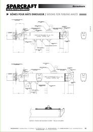
w w w . s p a r c r a f t . c o mM Â T S - BÔMES - ACCASTILLAGEMASTS - BOOMS - HARDWARESPARCRAFT - FRANCERue Blaise Pascal Z.I. <strong>de</strong> PérignyF-17185 PérignyTEL : +33 (0)5 46 45 90 45FAX : +33 (0)5 46 45 36 59e-mail : contact@<strong>sparcraft</strong>.comSPARCRAFT - USA3901 Pine Grove CircleCHARLOTTE NC 28206 USATEL : +01 (704) 597 15 02FAX : +01 (704) 597 09 61e-mail : info@sprarcraft-us.comwww.<strong>sparcraft</strong>-us.comGRÉEMENT COURANT & DORMANTSTANDING & RUNNING RIGGINGSPARCRAFT RIGGINGRue Blaise Pascal Z.I. <strong>de</strong> PérignyF-17185 PérignyTEL : +33 (0)5 46 34 31 27FAX : +33 (0)5 46 34 22 60e-mail : info@<strong>sparcraft</strong>-rigging.comwww.<strong>sparcraft</strong>-rigging.comSYSTÈMES D’ENROULEMENTFURLING SYSTEMSFACNOR (FURLING DIVISION)BP 222 Parc d’activitéF-50550 St Vaast-la-HougueTEL : +33 (0)2 33 88 50 22FAX : +33 (0)2 33 23 14 27e-mail : info@facnor.comwww.facnor.comSPARCRAFT ATLANTIQUEBâtiment Defvan Z.A. du LandyF-56450 THEIXTEL : +33 (0)6 18 12 59 90plegoff@<strong>sparcraft</strong>.comNon-binding document Design and photo credits: E.B. / Groupe Losange - Sparcraft - 2010 - Merci à AD Cherbourg - Special thanks to Eurospar, Sailspar, and Hahnfeld-Masten.Prix / Price : 10 eurosSPARCRAFT - SPARCRAFT RIGGINGLOSANGESPARCRAFT US - FACNOR - ESIM
SPARCRAFTTMA WORLDWIDE NETWORKStepping a mast is an involved and preciseoperation. We therefore advise you hire theprofessional services of a rigger. Pleasevisit our website to see the list of Sparcraftagents. SPARCRAFT reserve the right tomodify without <strong>notice</strong> all or part of theseinstructions.Version française page 26w w w . s p a r c r a f t . c o m
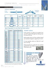
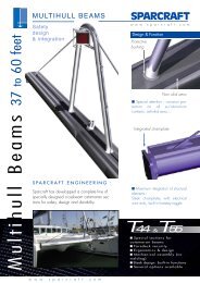
PROCEDURE FOR FITTING THE RIGGINGAND STEPPING THE MASTThank you for the interest you have shown in the Sparcraftbrand. This document offers some advice to ensure that themast and rigging installation goes well. So that you can followthe recommen<strong>de</strong>d procedure it gives a step by stepaccount from unpacking the mast to its first use. This adviceis a gui<strong>de</strong> only and is not inten<strong>de</strong>d to replace the services ofa professional.In short, there are several types of rig:- masthead rig: The forestay is attached to the topof the mast;- fractional rig: the forestay is attached below thetop of the mast (9/10 or 7/8 of the way up themast for example);- with one, two or more sets ofsprea<strong>de</strong>rs, which may beswept-back (fig.2) orin-line (“in the axis”);FIG. 2Swept-back sprea<strong>de</strong>rs:angling of sprea<strong>de</strong>rs in relationto the axis of the mast- continuous (gui<strong>de</strong>d shrouds,the opposite which are not fixed to the tip of thesprea<strong>de</strong>rs) or on the contrary, discontinuous(section 5.3 and 5.4);- the mast may be fitted to the <strong>de</strong>ck or keelstepped (fig1).These various types of rig require different installationsand adjustments (see sections 5.3 and 13).We have <strong>de</strong>dicated section 12 to catamaran rigs.FIG. 1 - planted mast(fitted to the keel)N.B. For furling masts please consult the relevantinstructionsREMINDER AND CHECKS DURING THE PROCEDURE: see the end ofthis documentwww.<strong>sparcraft</strong>.com / 1
1UNPACKING AND CHECKINGInventoryDepending on where it is being <strong>de</strong>livered, the mastis packed in various materials: plastic, padding,woo<strong>de</strong>n battens.- carefully unpack the mast and check the overall condition in or<strong>de</strong>rto i<strong>de</strong>ntify any problems;- the condition of the packaging can be a <strong>de</strong>termining factorin this checking process;- before being sent, all our masts are inspected byour experts. The rare problems that are found tendto occur during transportation, which is why it isimportant to carry out a check on <strong>de</strong>livery;- sort out and count all the necessary parts;- when unpacking, avoid cutting the messenger lines and scratchingthe mast. Please be careful when using a cutter, knife or other sharpinstrument.Please be careful to avoid scratching the mastREMINDER- Sparcraft masts are <strong>de</strong>livered with running rigging (orthe halyard messenger lines) attached and stuck to themast;- spars and standing rigging are kept separate in or<strong>de</strong>r tominimise the risk of damage during transportation.2 /www.<strong>sparcraft</strong>.com
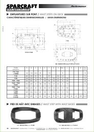
Traceability: number check.For Sparcraft, each rig is unique, which is why we giveit an i<strong>de</strong>ntification number enabling you to know whereit has come from and which route it has taken. This is away for us to guarantee the quality. Please note downthese numbers in this booklet.- MAST (engraved near where the sail joins) N° _ _ _ _ _ _ _ _ _ _ _ _- BOOM (near the gooseneck) N° _ _ _ _ _ _ _ _ _ _ _ _- SPREADERS N° _ _ _ _ _ _ _ _ _ _ _ _- STANDING (on the bottom tip of the backstay) N° _ _ _ _ _ _ _ _ _ _PREPARATION OF THE MAST AND EQUIPMENT2Preparation of the tools necessary for the operation- i<strong>de</strong>ntify each element of the mast and standing rigging;- prepare the tools required for stepping the mast and theadjustments;- use the right equipment: this avoids damaging the equipment (malletinstead of a hammer, for example).Setting up and protecting the mast- set the mast down on Trestles, which have beenprotected by foam or other soft material.The centre of gravity of the mast (where it is balanced to work on) is<strong>de</strong>fined by a red mark on the mast packing. Indicate this mark (afterunpacking) with a strip of red tape.www.<strong>sparcraft</strong>.com / 3
3Drilling holes and pre-assemblyWe are talking here of a pre-assembly, not a final assembly- without fixing - of the aerials and lights:- pass the cables through using the messenger lines;- carry out the drilling, put in position the brackets;- carry out the pre-assembly of the mast head equipmentand <strong>de</strong>ck lighting, taking care not to damage the sheaves;- run through the cables that are required (additional lightsand VHF) or planned for the future;- Fill in around the holes to make them watertight;- position the VHF aerial upsi<strong>de</strong> down (risk when being lifted);- check the holes at the foot of the mast.Take particularcare when drillingnot to damageanythingPRE-ASSEMBLY CONNECTIONSPassing through the messenger linesYou can leave one or more messenger linesin case of any future connections.4RUNNING RIGGINGFront si<strong>de</strong> - fore halyards / Rear si<strong>de</strong> - rearhalyardsRun the halyards through using the messenger lines (not forthe pre-assembled halyards). Position the mast:- front si<strong>de</strong> downwards for the fore halyards;- rear si<strong>de</strong> downwards for the rear halyards;- check that all of the halyards are clear, (not caught anywhere),are parallel to the exit holes from the mast and arefree to move (exit from sheaves);- make a knot to hold each halyard in place (“figure of eight knot”).4 /www.<strong>sparcraft</strong>.com
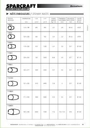
FITTING THE STANDING RIGGINGThe standing rigging ("si<strong>de</strong> rigging") is fitted by starting at thetop of the mast and gradually feeding it down step by step to thefoot. The diagonal rigging (intermediate shrouds) and the sprea<strong>de</strong>rsare fitted during this process.The standing rigging will be placed on either si<strong>de</strong> of the mast.Fitting of shells5The shells are placed into the mast (before the cables are threa<strong>de</strong>dthrough the holes in the sprea<strong>de</strong>rs) in three simple stages:5.1Fitting Rotation Positioning90°An aluminium rivet is placed into the top hole to stop the shell falling outduring the stepping of the mast. Ensure the shell is in place before insertingthe rivet. This rivet does not serve any structural purpose, as oncethe mast is erected, the shells are kept firmly in place by the rigging tension.Types of masthead rigfixing a safety rivet- Si<strong>de</strong> shells: come ready fitted (with rivet attachment);- T-terminal: Line up the terminal at 90° and turn it 90° to fit into its housing.Fix a stopper in place to prevent it falling out (particularly for therunners);- External masthead rig (on tangs): never apply tension to the bolts thatpass through (risk of squashing the mast). Secure the attachment makingsure to open up the split pin once the swage eyes are in place.www.<strong>sparcraft</strong>.com / 5
5.2Fitting of sprea<strong>de</strong>rs- the sprea<strong>de</strong>rs must be carefully positionedand fixed at each panel of themast. The use of a mallet is recommen<strong>de</strong>dto avoid scratching the aluminium;- place the sprea<strong>de</strong>rs top si<strong>de</strong> up;- open the pins very slightly (to ensurethe sprea<strong>de</strong>rs are firmly fixed in placeand that there is no movement in thesprea<strong>de</strong>rs).Dihedralangle = 5°Split pin to beopened to 90°or use split ringsPlease note: it is possible to use a clamp tofit the sprea<strong>de</strong>rs on steel bars: follow theinstructions inclu<strong>de</strong>d with these sprea<strong>de</strong>rs.6 /www.<strong>sparcraft</strong>.com
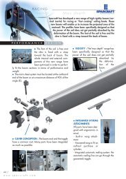
Sprea<strong>de</strong>r tip fittingsFor continuousriggingAttach the tip fittings to the ends of thesprea<strong>de</strong>rs (continuous and/or discontinuous),so they can receive the top andintermediate shrouds.For discontinuousriggingSpecial precautionswith discontinuous riggingIf using discontinuous rigging, each cable must bealigned and placed so that all the parts are correctlypositioned:- Clevis pin on top, the corresponding eye on thebottom;- release the turnbuckles on the diagonal rigging(See figure for or<strong>de</strong>r V / D).These should be loosened all the way. Vertical 25.3Diagonal 2V2Release the tensionon the diagonalrigging as much aspossibleVertical 1Diagonal 1V1D2Pay particular attention to the fittingof the jumper. Angle of jumpersV2D3 and dihedral angle of5° upwards (see figure page 6)www.<strong>sparcraft</strong>.com / 7
5.4Special precautions with continuous rigging- check the cable housing (front or rear) is correctlypositioned before screwing the sprea<strong>de</strong>r tip fittings inplace: the way the top and intermediate shrouds passthrough the tips of the sprea<strong>de</strong>rs is <strong>de</strong>termined by theposition or<strong>de</strong>r of the cables on the chain plate on the boat(in general the lower holes on the chain plate are for theintermediate shrouds);- Otherwise, the <strong>de</strong>fault arrangement is: cap shrouds onthe back and intermediate shrouds on the front.Check the positioning of the cables before fixing the tips of the sprea<strong>de</strong>rs5.55.65.7Line up the si<strong>de</strong> rigging alongsi<strong>de</strong> the mast- continuous rigging: si<strong>de</strong> by si<strong>de</strong> while carefully protecting the mastand the turnbuckles (see below);- discontinuous rigging: tighten V1 by attaching a rope between theboom vang attachment and each turnbuckle and stretch D1 out along themastFit the backstay and runners- backstay: check the direction of the pin (pin towards the mast);It is advisable to protect this with sticky tape;- runners: pins towards the mast.Fit the forestay- Staysail stay (if applicable): attach it to the length of the mast;- forestay and furler: Lay the furler on the ground on padding to protectit (do not store the furler on the mast) and fit it at the end.8 /www.<strong>sparcraft</strong>.com
PRECAUTIONS BEFORE STEPPING THE MASTChecks and preparation of the turnbuckles6- unscrew the turnbuckles (pin removed) by turning thebody clockwise;- the turnbuckles are <strong>de</strong>signed with right and left hand threads.Position the body with the right screw on the bottom (traditionalscrew direction);- Think ahead: with the mast stepped, nothing must stop theturnbuckles from being tightened quickly (shrouds and forestay)to keep the shape;- keep the turnbuckles clean. Lubricate if required with SparcraftRigging grease;- protect the turnbuckles (cloths and/or tape) to avoid knocks duringhandling.Final check- check each pin is in place;- tie the standing and running rigging to the mast (forestay slack);- check that the turnbuckles and pins are compatible with the <strong>de</strong>ck fittingsand chain plate;- Mast fitted to the keel: measure the distance un<strong>de</strong>r the <strong>de</strong>ck and comparewith the distance between the foot and <strong>de</strong>ck stop.Protect any parts that jut out- It is recommen<strong>de</strong>d that all sensitive elements of yourrig be protected. A simple piece of rigging tape can beplaced on clevis and split pins. This will help preventunnecessary wear to sails. This mark can also be usedas an indicator during checks on all the fittings.- attach the foam protection to the front si<strong>de</strong> of thesprea<strong>de</strong>rs to avoid contact with the furler when moving the mast.www.<strong>sparcraft</strong>.com / 9
6PRECAUTIONS BEFORE STEPPING THE MAST)Masthead equipment- Fitting of equipment (navigation lights,...) on land:complete this installation at the end. Cut down theamount of times you have to climb the mast and makesure they fit before stepping;- Fitting from the top: prepare the fragile elements (aerials and/or windindicators), but do not fix them until the mast is stepped and checked(temporary fitting of aerial upsi<strong>de</strong> down before lifting). Please consult theinstructions from the manufacturers of such equipment and the recommendationsfrom the crane-driver during the lifting process.Checking the cables and connections- any electric shock can cause corrosion.Please check the condition of the cables andthe bulbs in the navigation lights. Have them tested ifnecessary;- Check the electrical connections and protect them withan appropriate product.Final visual checkPlanted mast should read keel stepped mast : check the positionof the watertight system insi<strong>de</strong> the mast (generally foundat the lowest halyard exit). You should only see daylightthrough the central tube for the electric cables. No light shouldpass through the main section10 /www.<strong>sparcraft</strong>.com
HOISTINGPrecautions during hoistingThe operation needs to be carefully planned due to the high risksinvolved, concerning the equipment and the safety of thosetaking part in the operation.- Avoid lifting in strong winds;- stabilise the boat.- At each stage, all of the cables are together and the running andstanding rigging are attached to the foot of the mast except for the forestay(or furler) which is loose and ready to be attached.Please note: We are giving you a tried and tested method for stepping themast, but it is up to you to <strong>de</strong>ci<strong>de</strong> whether this is suitable <strong>de</strong>pendingon your rig configuration, the crane and the environment:SlingThe hook must be fitted with a safety catch. Add an additional turnaround the jaws of the sling.- place the sling strop above the centre of gravity of the mast asmarked by the sticky tape (balance point) and knot it tight using a bowline;- take the sling from its hoisting point to the bottomof the mast and fix it to the gooseneck fitting;- pull in and bring together any surplus strop;- tie a tow rope between the anchorage point and theboom vang attachment (or gooseneck fitting);- Depending on the size of the mast and configuration,prepare a tow rope from the tip of the top sprea<strong>de</strong>r.Continue togooseneckSafety procedures:Wrap theriggingaround themast andprotect theturnbucklesThe lifting and attachment strops must be suitable for the load and tightlyknotted. Position the mast above the <strong>de</strong>ck of the yacht. Gui<strong>de</strong> the mastinto place with the help of the tow ropes.7www.<strong>sparcraft</strong>.com / 11
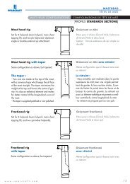
8PUTTING THE MAST IN PLACESecuring a <strong>de</strong>ck stepped mastFitting the furler: pleaseread the instructions suppliedby the manufacturer.- place the foot of the mast into its base;fix the standing rigging: forestay, babystay, cap shrouds,lower shrouds, runners, backstay just to secure the mast.Tighten the turnbuckles simply by hand to begin with (seebelow).8.1Securing a keel stepped mastThe mast must be perpendicular to the vertical of the boat.- fit the items (wedge and flange) from the mastsleeve kit. The <strong>de</strong>ck must be clear and the collar fixedwith flange ready to receive the mast;- two people gui<strong>de</strong> the mast into its collar above the<strong>de</strong>ck and give instructions before crossing the <strong>de</strong>ck.A third person helps with these operations and givesinstructions from insi<strong>de</strong> the boat.- pass the electric cables carefully through the <strong>de</strong>ckcollar;- lower the mast;- simple step: gui<strong>de</strong> the mast into its housing;- U-shaped step: the same to fix the mast with theaxis going through the simple step;The exact position of the axis <strong>de</strong>pends on the adjustmentrequired: the further forward the axis, thegreater the rake. The neutral point is of course in themiddle (see the adjustments section12).Neutral position in themiddle of the stepN.B.: to avoid any damage to the mast as it is lowered, protect it (plasticfilm or padding).12 /www.<strong>sparcraft</strong>.com
PUTTING THE MAST IN PLACE(continued)- fit the forestay to its attachment;- fit the lower shrouds, then the main shrouds. Hand tightenthe turnbuckles (Do not use a spanner) to obtain a balance(bd/td);- fit the backstay(s);N.B.: on some mo<strong>de</strong>ls, the backstay is calculated precisely toensure the correct tension when un<strong>de</strong>r strain.If it is difficult to fit: ensure that the mast is not leaning forward,release the stay completely (turnbuckles or link plates),release D1 (lower shrouds), tighten slightly V1 (cap shrouds)and using the mainsail halyard fixed to a solid point (cleat, travellertrack), swing the mast backwards to allow the backstay(s) to be attached.- With the backstay(s) in place, tighten by hand all of the turnbuckles tosecure the mast.Free the slingWhen the mast is safely in place and secured, release the sling.Remove the return knot at the foot of the mast.Sleeve kit- Line up the bolts in their respective placesand squeeze the elastomer seal in or<strong>de</strong>r toensure it is completely watertight. Tobe safe, ensure that the seal is uniformlytight, in or<strong>de</strong>r to avoid anyrisk of leaking. This needs to befirmly tightened. We recommend that for the aluminiumsystem with screwed seals that the screw be protectedwith a special product (duralac, Teg gel...)- have available a silicon joint or PU glue to ensurecontact between the seal and mast and the sleeve in thehousing. Leave to dry for 24 hours before use;8.2www.<strong>sparcraft</strong>.com / 13
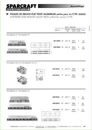
9MAST FITTED TO THE KEELDeck tie rodsAs the halyards are attached to the collaron the <strong>de</strong>ck, it is essential to compensatefor the load they exert upwards.It is therefore necessary to fitone or two <strong>de</strong>ck tie rods,according to the size of themast, between the collar andthe stepped part of the mast.If this key part is forgotten, seriousstructural problems could result.Mast jack: please see the specificinstructions10HALYARD EXITSAngling the halyard channelsAngle the blocks to suit thehalyard exitsand your choices of on-board organisation.- bring the running rigging to the foot of themast to allow the layout to enter the cockpit andgo on to the blocks;- for the halyard layouts: angle the blocks to themast exits to avoid early wear on the runningrigging. The way it is spread out <strong>de</strong>pends onthe recommendations from the manufacturer14 /www.<strong>sparcraft</strong>.com
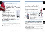
BOOM AND POLEInstallation of theboom11Positioning theboom on the ball joint on thegooseneck fitting:-manoeuvres with a short-han<strong>de</strong>dcrew:With the help of the topping lift ordirectly with the mainsailhalyard, ease the weight on theboom;-once raised to a comfortable position, insert the front tip of the boominto the gooseneck.N.B.: for some mo<strong>de</strong>ls, the ball joint is fitted in a different direction (<strong>de</strong>liveredupsi<strong>de</strong> down). Keep it this way up (Do not turn over).- fit seals or collars on either si<strong>de</strong> of the joint, according to the originalassembly;- lock in position with a pin or bolt.Taking in a reef withcontinuous riggingReefing is carried out from the cockpit,and the fitting process is no differentthan that of a classic boom.Pole- check the mechanisms are working properly.Lubricate if necessary;- adjust the lengths of the pole up and pole downhaul.Mark adjustment points on these with the mastin place.www.<strong>sparcraft</strong>.com / 15
12CATAMARANSCATAMARANS - Special instructionsCatamarans are usually fitted with self-standing systems,which keep the mast in place with a forestay and two topstays fastened to chain plates on the hull.These self-standing masts can be divi<strong>de</strong>d into twogroups:- pivoting masts called teardrop masts or wing masts(wing masts as found on Formula28 and F 40);- fixed masts.These fixed masts are rigged in different ways:- masts on tripods: the sprea<strong>de</strong>rs are connected tothe front by a martingale and a jumper enablingthe mast to be ma<strong>de</strong> rigid lengthways;- intermediate shapes: the mast is simply supportedsi<strong>de</strong>ways by the sprea<strong>de</strong>rs and a bigger set ofshrouds (not self-standing lengthways, so no jumpers);- chimney masts: with no front jumper nor sprea<strong>de</strong>rs,but the shrouds inclu<strong>de</strong> lower shrouds andoccasionally a staysail stay.CATAMARANS - Pre-adjustment before fittingCatamaran rig(diamond rig)The special characteristics of the self-standing rigs on multihulls meanthat the lateral diamond shapes and jumpers are un<strong>de</strong>r tension and preadjustedbefore stepping the mast in or<strong>de</strong>r to obtain a rigid structure.See also the special instructions.16 /www.<strong>sparcraft</strong>.com
ADJUSTMENTS, RECOMMENDATIONSMarks13- the mast must be placed lengthways in the boat;- to carry out the adjustments, use the mainsail halyard in or<strong>de</strong>r to measurethe distance to an equidistant point on either si<strong>de</strong>.Rakeϕ = 1 to 1,5°- finely adjust in or<strong>de</strong>r to find the best “Rake/Prebend”(see below);- the tension of the forestay and the backstay should, ifpossible, be the same as that of the shrouds and shouldinduce a rake ϕ (angled backwards) by about 1 to 1.5°.- e.g.: 10-metre mast: mastheadpushed back by about 20 cm.This mast rake will <strong>de</strong>terminewhether the boat has a leehelm or a weather helm.The greater the rake, the more the weather helmand vice versa.Adjust only for a very small amount of pre-bend onfurling masts (see instructions)Tension of the rigging at the masthead and on the sprea<strong>de</strong>rs:1.adjust the rake with the forestay, then tighten the backstay (see section13.1);2. centre the mast si<strong>de</strong>ways using the cap shrouds and tighten them symmetricallyin or<strong>de</strong>r to obtain an upright mast;3.apply tension to the rear and front lower shrouds allowing a slight prebendthen adjust the intermediate shrouds checking the cross-section isupright (looking along the sail track);4. apply the final tension maintaining the same or<strong>de</strong>r and then carry outchecks un<strong>de</strong>r sail. The tension on the cap shrouds and the lower rearshrouds should be high.13.113.2www.<strong>sparcraft</strong>.com / 17
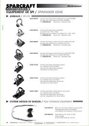
13.3ADJUSTMENTS, RECOMMENDATIONSTension of the head rigging with swept-back sprea<strong>de</strong>rsSpecial instructions: swept-back sprea<strong>de</strong>rs support the mast from thesi<strong>de</strong>s and lengthways. By increasing the tension, the mast is pushed forwardat the level of the sprea<strong>de</strong>rs creating a curve. Carry out thefollowing step by step procedure to obtain the correct rake /pre-bend / tension:1. adjust the rake with the forestay, then tighten the backstay(cf 13.1);2. centre the mast si<strong>de</strong>ways using the shrouds and tightenthem symmetrically to obtain a regular bend of the mast(20 cm for a 35’);3. apply tension to the lower shrouds, then the intermediateshrouds checking the mast is upright and with theright bend;4.Complete the adjustment to the tension in the sameor<strong>de</strong>r and then after sailing trials. The tension on the capshrouds (V1) and lower shrouds (D1) must be high.Regularly check the vertical alignment along the sail track.Please note for discontinuous rigging: the turnbuckles on the intermediates(D2) must be completely open during the adjustment of the V1D1, and canbe closed once the tension of V1D1 is complete. The tension on D2 mustbe low: close the turnbuckles by hand and two spanner turns.13.4Tension on the fractional riggingwith swept-back sprea<strong>de</strong>rsProceed as in section 13.3, but take intoaccount the following characteristics:- increasing the tension on the capshrouds pushes the mast forward creating apre-bend (step ➀);- tightening the lower and intermediateshrouds will reduce the bend (step ➁);- a regular pre-bend is required.;18 /www.<strong>sparcraft</strong>.com
ADJUSTMENTS, RECOMMENDATIONS- when the lower shrouds have been tightened and theintermediate shrouds adjusted , the pre-bend valueshould be approximately half the mast section <strong>de</strong>pth(about 10/12 cm for a 35'). This value can increase toone mast section <strong>de</strong>pth if required;- adjust the running backstays to finish, as they work inopposition to the rest of the rig;- when the back angle of the sprea<strong>de</strong>rs is below 15°, the tension requiredon the running backstay is high, in or<strong>de</strong>r to support the mast backwards;- If the rear angle of the sprea<strong>de</strong>rs is above 15°, the sprea<strong>de</strong>rs will alsosupport the mast lengthways and the tension on the backstay does not needto be so high. However, be careful not to exceed the limit to avoid a mastinversion.Tension of fractional rigging within-line sprea<strong>de</strong>rsmini1/2 L.max1 L.13.5- proceed as in section 13.3. Note:- The rigging with in-line sprea<strong>de</strong>rs is adjusted as withtop rigging, the only difference being theaddition of backstays for the tension of the forestay;- The mast should always be adjusted with acertain bend forwards/backwards, otherwise thecurve of the mast may be invertedparticularly in strong winds.Avoid a negativebend (“curvedbackwards”)the babystays adjust the bend of the mid-sectionof the mast. If they are too tight in relationto the backstays, they can cause theinversion of the mast bend.www.<strong>sparcraft</strong>.com / 19
14ADJUSTMENTS AND SEA TRIALSChecking adjustments un<strong>de</strong>r sail- check the adjustments in mo<strong>de</strong>rate or light winds on calmseas. It is preferable if you can avoid having to <strong>de</strong>al withmanoeuvres by taking aboard some experienced crewmen;- check the alignment of the mast upwind looking along thesail track (lateral alignment) which should be straight onboth tacks;- the leeward cap shrouds should not be completely slack.If this is the case on both si<strong>de</strong>s, take in (once moored ashore) the samenumber of turns on each si<strong>de</strong> of the mast. Redo the adjustment as manytimes as necessary until fine-tuned.N.B.: a new rig requires an additional adjustment after its first sailingtrips.Too slackToo tautToo slackTootautToo slackSi<strong>de</strong> adjustmentDiagonal adjustment (intermediate shrouds)Remarksconcerning discontinuous rigging:- before applying tension to V1D1, it is imperative that you ease thediagonals first.N.B.: some classes of yacht have their own specific information concerningthe tension of the rigging. Please consult these documents.20 /www.<strong>sparcraft</strong>.com
ADJUSTMENTS AND SEA TRIALSOnce back in harbour14- make a mark to i<strong>de</strong>ntify the adjustment positiononce back in port;- note down all these adjustments in or<strong>de</strong>rto be able to re-use them whenever requiredafter wintering;N.B.: take into account the stretching ofcables over time.- if the turnbuckles have been adjusted at sea, please check toensure that the pin is in place and that they are open;- You can protect the sails by using a protector on the turnbucklesand sticky tape on the pins.Maintenance- Regularly check the condition of the standing rigging. Use the servicesof an expert to carry out a complete service check, as required;- when preparing the yacht for winter, rinse off the aluminium parts:mast, foot of the mast, boom, boom vang, pole,...;- also rinse off the running rigging;- check the halyards and their sheaves;- check the condition and movement of the reefingpennants.For operations to be carried out at the top of themast: make sure you have the right comfortablesafety gear.Trimming the sailsThe techniques used to obtain the perfect trimming also <strong>de</strong>pend on theshape of the sails and the characteristics of the boat. It is thereforeimportant to obtain advice and consult your sailmaker.www.<strong>sparcraft</strong>.com / 21
15ADJUSTMENT INDICATIONSMasthead rigIn-linesprea<strong>de</strong>rsSwept-backsprea<strong>de</strong>rsFractional rigSwept-backsprea<strong>de</strong>rsIn-linesprea<strong>de</strong>rs1. Rake adjust the forestay, then apply tension to the running backstay2. Si<strong>de</strong>+ pre-benda straightmastadjust the cap shrouds symmetrically to obtain:a regularpre-benda regularpre-benda straightmast3. TensionTighten thelowershrouds foreand aft,then adjustthe intermediateshroudsTighten thelowershrouds, thenadjustthe intermediateshroudsMore tension onthe cap shroudspushes the mastforward creatinga bend;More tension onthe lower andintermediateshrouds reducesthe bend;Is adjustedlike a mastheadrigapart fromthe tensionon the runningbackstays4. FinaladjustmentCommentsApply the final tension respecting the same or<strong>de</strong>rCheck un<strong>de</strong>r sail making sure the mast is straightAdjustment ofthe intermediatesat eachdiagonal turnbuckleAdjust the runningbackstay atthe end (works inopposition to therest of the rigging)Adjust toobtain a certainbendforwards orbackwards toavoid aninversion ofthe curve ofthe mast instrong windsAdjust only for a very small amount of pre-bend on furling masts22 /www.<strong>sparcraft</strong>.com
COMMENTSwww.<strong>sparcraft</strong>.com / 23
UNPACKING AND CHECKING P2 to 31234 Inventory / Remin<strong>de</strong>r Note down the serial numbers- Mast N° _ _ _ _ _ _ _ _ _ _ _ _- Boom N° _ _ _ _ _ _ _ _ _ _ _ _- Sprea<strong>de</strong>rs N° _ _ _ _ _ _ _ _ _ _ _ _- Standing rigging N° _ _ _ _ _ _ _ _ _ _ _ _PREPARATION mast and equipment Preparation of the tools required Installation of the mast and centre of gravityPRE-ASSEMBLY CONNECTIONS Drilling and pre-assemblyRUNNING RIGGING Passing the halyards through and checksP3P4P4FITTING THE STANDING RIGGING P5 to 8567 Insertion of shells / types of masthead gear (5.1) Installation of sprea<strong>de</strong>rs and tip fittings (5.2) Precautions with discontinuous rigging (5.3) Precautions with continuous rigging (5.4) Line up all the si<strong>de</strong> rigging against the mast (5.5) Fit the runner and backstays (5.6) Fit the forestay (5.7)PRECAUTIONS BEFORE STEPPING THE MAST P9 to 10 Checking and preparing the turnbuckles Protection Electrical equipment Visual checkHOISTING Precautions when hoisting The sling Safety during the manoeuvreP1124 /www.<strong>sparcraft</strong>.com
P12 to 13P U T T I N G T H E MAST IN PLACE Care with the mast Special instructions for a mast fitted to the keel (8.1) Sleeve kit (8.2)8P14 Fitting <strong>de</strong>ck tie rodsP14 Angling the blocksMAST FITTED TO THE KEELHALYARD EXITS910P15BOOM AND POLE Installation of the boom / taking in a reef with continuous rigging PoleP16CATAMARANS Special characteristics / Pre-adjustment before fitting1112P17 to 19A D J U STMENTS, RECOMMENDATIONS Marks Rake (13.1) Tension of the masthead rigging with in-line sprea<strong>de</strong>rs (13.2) Tension of masthead rigging with swept-back sprea<strong>de</strong>rs (13.3) Tension of fractional rigging with swept-back sprea<strong>de</strong>rs (13.4) Tension of fractional rigging with in-line sprea<strong>de</strong>rs (13.5)P20 to 21ADJUSTMENTS AND SEA TRIALS Checking the tuning un<strong>de</strong>r sail Precautions on arrival back in harbour Maintenance / Trimming the sails1314P22ADJUSTMENT INDICATIONS15www.<strong>sparcraft</strong>.com / 25
SPARCRAFTTMA WORLDWIDE NETWORKLa mise en place d’une mâture est une opération délicateet rigoureuse que nous vous conseillons vivement<strong>de</strong> faire effectuer par un professionnel du gréement.Pour connaître la liste <strong>de</strong>s agents SPARCRAFT, merci<strong>de</strong> consulter notre site internet.SPARCRAFT se réserve le droit <strong>de</strong> modifier sans préavistout ou partie <strong>de</strong>s présentes indications.w w w . s p a r c r a f t . f r26 /www.<strong>sparcraft</strong>.fr
PROCÉDURE DE MÂTAGE & POSENous vous remercions <strong>de</strong> faire confiance à la marqueSparcraft. Ce document suggère quelques conseils afin d’assurerle bon déroulement <strong>de</strong> l’installation du gréement et dumâtage. Il suit étape par étape les opérations, du déballagedu mât aux premières utilisations, afin <strong>de</strong> visualiser la procédureconseillée. Ces conseils ne sont toutefois qu’indicatifs etne dispensent pas <strong>de</strong>s services d’un professionnel.En résumé, il existe plusieurs types <strong>de</strong> gréement :- gréement en tête : l’étai est fixé en tête <strong>de</strong> mât;- gréement fractionné : l’étai est ancré en <strong>de</strong>ssous<strong>de</strong> la tête <strong>de</strong> mât (à 9/10 ou 7/8 par exemple <strong>de</strong>la hauteur du mât);- à un ou plusieurs étages <strong>de</strong>barres <strong>de</strong> flèche qui peuventêtre poussantes(fig.2) ou non poussantes(“dans l’axe”);- continu (haubans guidésFIG. 2Barres <strong>de</strong> flèche poussantes :angulation <strong>de</strong>s barres <strong>de</strong> flèchespar rapport à l’axe du mâtmais non fixés dans l’embout <strong>de</strong> barre <strong>de</strong> flèche)ou, inversement, discontinu (section 5.3 et 5.4);- le mât peut être posé sur le pont ou implanté surquille (ou “emplanté”, fig1).FIG. 1 - mât emplanté(posé sur quille)Ces différents types <strong>de</strong> gréement impliquent <strong>de</strong>sinstallations et <strong>de</strong>s réglages différents (voir sections5.3 et 13). Nous avons consacré la section12 aux gréements <strong>de</strong>s catamarans.Nota mâts enrouleurs : se référer également à la <strong>notice</strong> spécifiqueRAPPEL & CONTRÔLE DE LA PROCÉDURE : voir en fin <strong>de</strong> document.www.<strong>sparcraft</strong>.fr / 27
1DÉBALLAGE & CONTRÔLEInventaireEn fonction <strong>de</strong> sa <strong>de</strong>stination, le mât est emballéavec différents matériaux : plastique, moquette,lattes <strong>de</strong> bois.- déballer le profil avec précaution et repérer le point d’équilibre(voir P 3);- contrôler son état général afin <strong>de</strong> déceler toute anomalie;l’état <strong>de</strong> l’emballage peut être un indicateur déterminantlors <strong>de</strong> cette phase <strong>de</strong> contrôle. Avantleur départ, tous les mâts sont inspectés par nosspécialistes. Les rares problèmes rencontrés surviennentmajoritairement lors du transport, d’oùl’importance du contrôle à réception du matériel;- réunir et recenser toutes les pièces nécessaires;- lors du déballage, prendre soin <strong>de</strong> ne pas couper les messagers et <strong>de</strong>ne pas rayer le profil. Cutter, couteau ou autres instruments tranchantsdoivent être utilisés avec précaution.Attention à ne pas rayer le profilRappel- les mâts Sparcraft sont livrés avec le gréement courant(ou les messagers <strong>de</strong> drisses) lové et filmé à même le profil;- les espars et le gréement dormant sont dans un conditionnementséparé (afin d’isoler le matériel susceptible <strong>de</strong>raguer pendant le transport et pourrait ainsi détériorer unélément <strong>de</strong> mâture).28 /www.<strong>sparcraft</strong>.fr
Traçabilité : relevé <strong>de</strong>s numérosPour Sparcraft, votre gréement est unique, c’est pourquoinous lui attribuons une i<strong>de</strong>ntité vous permettant <strong>de</strong>connaître ses origines et son acheminement. C’est unegarantie <strong>de</strong> transparence et <strong>de</strong> qualité. Notez donc cesnuméros sur ce livret.- MÂT (gravé près <strong>de</strong> l’entrée <strong>de</strong> voile) N° _ _ _ _ _ _ _ _ _ _ _ _- BÔME (près du vit <strong>de</strong> mulet) N° _ _ _ _ _ _ _ _ _ _ _ _- BARRES DE FLÈCHE N° _ _ _ _ _ _ _ _ _ _ _ _- DORMANT (sur l’embout bas du pataras) N° _ _ _ _ _ _ _ _ _ _ _ _PRÉPARATION MÂTURE & MATÉRIELPréparation <strong>de</strong>s outils nécessaires à l’opération- i<strong>de</strong>ntifier chaque élément <strong>de</strong> mât et <strong>de</strong> gréement dormant;- préparer les outils utiles à l’opération <strong>de</strong> mâtage puis <strong>de</strong> réglage;- adapter l’outillage : cela permet d’éviter <strong>de</strong> détériorer le matériel (mailletau lieu d’un marteau par exemple).Installation et protection du mât- installer le mât sur <strong>de</strong>s tréteaux préalablement protégés par<strong>de</strong>s mousses ou autres matériaux tendres.Le centre <strong>de</strong> gravité du mât (point d’équilibre <strong>de</strong> manutention)est défini par une marque rouge sur l’emballage du mât. Reportercette marque sur le mât (après déballage) par du ruban adhésif rouge.2www.<strong>sparcraft</strong>.fr / 29
3Perçage et pré-montageIl s’agit <strong>de</strong> pré-monter - sans fixer - les “aériens” et feux :- passer les câbles à l’ai<strong>de</strong> <strong>de</strong>s messagers;- effectuer les taraudages, mettre en place les supports;- pré-monter les équipements <strong>de</strong> tête <strong>de</strong> mât et éclairagepont en prenant soin <strong>de</strong> ne pas atteindre les réas;- passer les câbles nécessaires (feux supplémentaires etVHF) ou prévus ultérieurement;- bien étanchéifier les zones <strong>de</strong> perçage;- bien isoler les matériaux;- positionner l’antenne VHF à l’envers (risque au grutage);- vérifier les sorties en pied <strong>de</strong> mât.Ne rienendommagerau perçagePRÉ-MONTAGE CONNECTIQUEPassage <strong>de</strong> messagersLaisser éventuellement un ou plusieurs messagerspour prévoir un branchement ultérieur.4GRÉEMENT COURANTDrisses avant face avant / drisses arrière face arrièrePasser les drisses à l‘ai<strong>de</strong> <strong>de</strong>s messagers (pour les drissesnon montées préalablement) en positionnant le mât :- face avant vers le sol pour les drisses d’avant;- face arrière vers le sol pour les drisses d’arrière;- vérifier que toutes les drisses sont “claires”, (sans contournement),parallèles à leurs sorties du mât, et libres <strong>de</strong> circulation(sorties <strong>de</strong> réas);- réaliser un nœud d’arrêt sur chaque drisse mise en tension(“nœud en huit”).30 /www.<strong>sparcraft</strong>.fr
POSE DU GRÉEMENT DORMANTLe montage du gréement dormant (“latéral”) s’effectue encommençant du haut du mât et en <strong>de</strong>scendant étape par étapeau pied <strong>de</strong> mât. Les diagonaux (haubans intermédiaires) et lesbarres <strong>de</strong> flèche sont montés au fur et à mesure <strong>de</strong> l’évolution.Le gréement dormant sera ensuite placé <strong>de</strong> part et d’autre <strong>de</strong> la section.Insertion <strong>de</strong>s coquilles5L’insertion <strong>de</strong>s coquilles dans le mât (avant le positionnement <strong>de</strong>scâbles dans les embouts <strong>de</strong> barre <strong>de</strong> flèche) est réalisée selon troisgestes simples :5.1Encastrement Rotation Positionnement90°Un rivet aluminium peut être fixé dans le trou supérieur pour éviter ledégagement <strong>de</strong> la coquille pendant le mâtage. Bien maintenir la coquilleen position avant d’insérer le rivet. Ce rivet n’a pas <strong>de</strong> fonction structurellecar une fois le mât érigé, les coquilles sont maintenues fermementen place par la tension du gréement.Types <strong>de</strong> capelagefixation d’un rivet <strong>de</strong> sécurité- coquilles latérales : livrées montées (avec fixation par rivets);- terminaisons en T : présenter l’embout à 90° et le retourner d’autantdans son logement. Fixer une retenue pour éviter toute sortie acci<strong>de</strong>ntelle(notamment pour les bastaques);- capelages extérieurs (à lattes) : ne jamais reprendre la tension sur lesécrous traversants (risque “d’écraser” le profil). Verrouiller les axes <strong>de</strong>fixation en prenant le soin d’ouvrir les goupilles une fois les embouts àoeil mis en place.www.<strong>sparcraft</strong>.fr / 31
5.2Installation <strong>de</strong>s barres <strong>de</strong> flèche- les barres <strong>de</strong> flèche (BDF) doiventêtre mises en place soigneusement etfixées avec leurs axes à chaque étage<strong>de</strong> la mâture. L’utilisation d’un mailletest conseillée pour éviter les rayures surl’aluminium;- poser les axes en les orientant “têtevers le haut”;- les goupilles seront minutieusementécartées (maintien <strong>de</strong>s axes dans uneposition confortable et sécuritaire, pas<strong>de</strong> jeu néfaste dans la barre <strong>de</strong> flèche).Dièdre = 5°Goupilles fenduesà écarter <strong>de</strong> 30° environou anneaux brisésNota : utilisation éventuelle d’un serrejoint<strong>de</strong> compression pour montage BDFsur barreau inox : selon la procédurejointe à ces barres <strong>de</strong> flèche.32 /www.<strong>sparcraft</strong>.fr
Embouts <strong>de</strong> barres <strong>de</strong> flèchepour gréementcontinuInstaller successivement chaque extrémité<strong>de</strong> barre <strong>de</strong> flèches continues et/ou discontinues,prêtes à recevoir les galhaubanset haubans intermédiaires (“inters”).pourgréement discontinuPrécautions gréements discontinusDans le cas d’un gréement discontinu, chaquecâble doit être aligné et disposé <strong>de</strong> façon à ceque toutes les pièces se positionnent logiquement :- chape en haut, l’œil correspondant en bas;- relâcher les ridoirs <strong>de</strong>s diagonaux(Voir figure pour ordre Vx / Dx).Ceux-ci doivent être <strong>de</strong>sserrés aumaximum.Verticale 25.3Diagonale 2Détendre lesdiagonaux aumaximumVerticale 1Diagonale 1V2V1D2Attention au montage du cavalier.Sens <strong>de</strong>s cavaliers V2D3 et angulation(dièdre) <strong>de</strong> 5° vers le haut (voirfigure page 6)www.<strong>sparcraft</strong>.fr / 33
5.4Précautions gréements continus- vérifier l’emplacement (avant ou arrière) <strong>de</strong>s câblesavant <strong>de</strong> visser l’embout <strong>de</strong> barre <strong>de</strong> flèche (B.D.F.) : lepassage <strong>de</strong>s galhaubans et inters dans l’embout <strong>de</strong> B.D.F.est imposé par l’ordre <strong>de</strong>s emplacements <strong>de</strong>s câbles surles cadènes du bateau (en général le perçage <strong>de</strong>scadènes est inférieur pour les haubans intermédiaires);- sinon par défaut : galhaubans sur l’arrière et haubansintermédiaires sur l’avant.5.55.65.7Vérifier le positionnement <strong>de</strong>s câbles avant fixation <strong>de</strong>s embouts <strong>de</strong> BDFRassembler le gréement latéral le long du mât- gréement continu : côté par côté en protégeant le mât et les ridoirs(cf ci-après);- gréement discontinu : tendre les V1 en attachant un cordage entre laferrure <strong>de</strong> hale bas et chaque ridoir et allonger les D1 le long du mât.Poser pataras et bastaques- pataras : vérifier le sens <strong>de</strong> l’axe <strong>de</strong> chape (goupille vers le mât);Protéger éventuellement avec du ruban adhésif;- bastaques : goupilles vers le mât.Poser l’étai- étai <strong>de</strong> trinquette (le cas échéant) : le fixer le long du mât;- étai + enrouleur : allonger à terre l’enrouleur sur une moquette <strong>de</strong> protection(ne pas stocker l’enrouleur le long du mât) et le poser en <strong>de</strong>rnier.34 /www.<strong>sparcraft</strong>.fr
PRÉCAUTIONS AVANT MÂTAGEVérification & préparation <strong>de</strong>s ridoirs6- dévisser les ridoirs (goupille retirée) en tournant la cagedans le sens <strong>de</strong>s aiguilles d’une montre;- les ridoirs sont conçus avec un filetage “pas à droite” d’un côtéet “pas à gauche” <strong>de</strong> l’autre. Positionner la cage avec le “pasà droite” en bas (serrage traditionnel);- anticiper : mât posé, rien ne doit gêner le serrage rapi<strong>de</strong><strong>de</strong>s ridoirs (haubans et étai) pour maintenir le profil;- maintenir les ridoirs en propreté. Lubrifier si nécessaireavec une graisse Sparcraft Rigging;- protéger les ridoirs (chiffons et/ou adhésifs) pour éviter les chocs lors<strong>de</strong> la manutention.Vérification finale- vérifier chaque axe et chaque goupille;- lier le gréement dormant et courant au mât (étai libre);- vérifier également que les axes et types <strong>de</strong> ridoirs soient compatiblesavec les fixations <strong>de</strong> pont et cadènes;- mât posé sur quille : mesurer la distance sous le pont et compareravec la distance entre pied et cale d’étambrai sur le mât.Protection <strong>de</strong>s éléments saillants- Il est vivement recommandé <strong>de</strong> protéger tous les éléments sensibles <strong>de</strong>votre gréement. Une simple ban<strong>de</strong> adhésive assurechaque axe et goupille et empêche le frottement et l’usureprématurée <strong>de</strong>s voiles pendant la navigation. Cettemarque peut aussi servir <strong>de</strong> repère <strong>de</strong> contrôle <strong>de</strong> toutesles pièces montées.- fixer <strong>de</strong>s protections en mousse sur l‘avant <strong>de</strong>s BDF pouréviter le contact avec l’enrouleur lors <strong>de</strong>s manutentions du mât.www.<strong>sparcraft</strong>.fr / 35
6PRÉCAUTIONS AVANT MÂTAGEÉquipement <strong>de</strong> tête <strong>de</strong> mât- montage d’équipements (feux <strong>de</strong> navigation,...) àterre : finaliser la fixation <strong>de</strong> ces éléments en <strong>de</strong>rnier.Veiller au parfait montage afin <strong>de</strong> limiter le travail enaltitu<strong>de</strong>;- montage en aérien : préparer les éléments fragiles (antennes et/ouanémomètres) et ne les fixer qu’une fois le mât posé et assuré (fixationprovisoire <strong>de</strong> l’antenne à l’envers avant grutage). Se reporter égalementaux instructions <strong>de</strong> montage <strong>de</strong>s fabricants d’équipement et aux instructionsdu grutier <strong>de</strong> votre lieu <strong>de</strong> mâtage.Vérification <strong>de</strong>s câbles et connectique- toute décharge électrique peut provoquer une corrosion.Vérifier donc l’état <strong>de</strong>s câbles électriques et<strong>de</strong>s ampoules <strong>de</strong> feux <strong>de</strong> navigation. Lesfaire tester au besoin;- vérifier les connexions électriques et les protéger avecun produit adapté.Dernier contrôle visuel(SUITE)Mât emplanté : vérifier la position du système d’étanchéité àl’intérieur du mât (généralement au niveau <strong>de</strong> la sortie <strong>de</strong>drisse la plus basse). Seul le tube central <strong>de</strong> passage <strong>de</strong>scâbles électriques doit laisser passer la lumière du jour. Aucun“jour” ne doit être visible sur le périmètre <strong>de</strong> la section.36 /www.<strong>sparcraft</strong>.fr
LE GRUTAGEPrécautions <strong>de</strong> grutageL’intervention est <strong>de</strong> la responsabilité du grutier et doit être parfaitementpréparée en raison <strong>de</strong>s risques importants tant auniveau matériel que <strong>de</strong> la sécurité du personnel.- éviter notamment le grutage par vent fort;- stabiliser le bateau.- à cette étape, l’ensemble <strong>de</strong>s câbles est regroupé et le gréementcourant et dormant attaché en pied <strong>de</strong> mât hormis l’étai(ou l’enrouleur) libre et prêt à être fixé.Nota : nous vous présentons une métho<strong>de</strong> <strong>de</strong> mâtage éprouvée mais c’està vous qu’il appartient <strong>de</strong> juger son opportunité suivant la configurationdu gréement, <strong>de</strong> la grue et <strong>de</strong> l’environnement:L’élingueLe crochet doit être assorti d’une sûreté. Réaliser un tour mort supplémentaire<strong>de</strong> sécurité autour du croc <strong>de</strong> l’élingue.- enrouler la sangle homologuée <strong>de</strong> l’élingue autour du profil obligatoirementau-<strong>de</strong>ssus du centre <strong>de</strong> gravité du mât défini par unemarque adhésive (point d’équilibre) et nouée fortement par un noeud <strong>de</strong>chaise;- faire suivre l’élingue <strong>de</strong> son point <strong>de</strong> levée jusqu’enbas du mât et l’arrêter sur la ferrure <strong>de</strong> vit <strong>de</strong> mulet;- regrouper et amarrer le surplus éventuel <strong>de</strong> sangle;- frapper un bout <strong>de</strong> halage entre le point <strong>de</strong> fixationet la ferrure <strong>de</strong> hale bas (ou <strong>de</strong> vit <strong>de</strong> mulet);Faire suivrejusqu’auvit <strong>de</strong> muletSécurisation <strong>de</strong> la manœuvre :Entourerlegréementau mât etprotégerles ridoirs- suivant la taille du mât et la configuration, prévoiréventuellement un bout <strong>de</strong> halage à l’extrêmité <strong>de</strong>chaque barre <strong>de</strong> flèche N°1.Les bouts et sangles d’accrochage et <strong>de</strong> halage doivent être adaptés auxcharges et noués fermement. Présenter le mât au-<strong>de</strong>ssus du pont du voilier.Gui<strong>de</strong>r le mât pendant la manutention à l’ai<strong>de</strong> <strong>de</strong>s bouts <strong>de</strong> halage.7www.<strong>sparcraft</strong>.fr / 37
8MISE EN PLACE DU MÂTAssurer le profil (mât posé sur pont)Installation <strong>de</strong> l’enrouleur :se tenir aux instructionsdu fournisseur.- loger le pied <strong>de</strong> mât dans son embase;- fixer le gréement dormant : étai, bas étai, galhaubans, bashaubans, bastaques, pataras juste pour assurer le profil.Serrer les ridoirs uniquement à la main dans ce premiertemps (cf ci-après).8.1Mât posé sur quilleLe mât doit être alors à la perpendiculaire verticale du bateau.- placer les éléments (cale et bri<strong>de</strong>) du kit d’étambrai.Le pont est dégagé et la collerette d’étambraifixée avec ses poulies, prête à recevoir le mât;- <strong>de</strong>ux personnes gui<strong>de</strong>nt le profil dans sa cage au<strong>de</strong>ssus du pont et donnent les directives avant traverséedu pont. Une troisième assiste les opérations etdonne les directives <strong>de</strong> l’intérieur du bateau.- passer tous les câbles électriques avec précautiondans l’étambrai;- faire <strong>de</strong>scendre le mât;- emplanture réduite : amener le mât dans son logement;- emplanture en “u” : i<strong>de</strong>m puis fixer le mât avecl’axe traversant <strong>de</strong> l’emplanture réduite ;Le choix <strong>de</strong> la position <strong>de</strong> l’axe est fonction duréglage souhaité : plus l’axe sera avancé, plus laquête sera importante. Le point neutre étant évi<strong>de</strong>mmentau milieu (voir les réglages section12).Position neutre <strong>de</strong> l’axeau milieu <strong>de</strong> l’emplantureNota : pour éviter toute détérioration du profil lors<strong>de</strong> la <strong>de</strong>scente, protéger celui-ci (film plastique ou bout <strong>de</strong> moquette).38 /www.<strong>sparcraft</strong>.fr
MISE EN PLACE DU MÂT(SUITE)- capeler l’étai sur sa ferrure;- capeler les bas haubans puis les haubans. Serrer les ridoirsà la main (et non à la clé) <strong>de</strong> façon équilibrée (bd/td);- capeler le ou les patara(s);Nota : sur certains modèles, le pataras est calculé au plusjuste pour assurer une tension correcte sous charge.Si la mise en place est difficile : s’assurer que le mât n’est passur l’avant, relâcher l’étai complètement (ridoirs ou lattes),relâcher les D1 (bas haubans), prendre légèrement les V1 (galhaubans)et s’ai<strong>de</strong>r <strong>de</strong> la drisse <strong>de</strong> GV capelée sur un point fixe soli<strong>de</strong> (taquet,barre d’écoute), basculer le mât sur l’arrière et permettre l’accrochagedu ou <strong>de</strong>s patara(s).- pataras en place, reprendre manuellement et <strong>de</strong> façon régulière l’ensemble<strong>de</strong>s ridoirs pour sécuriser le mât.Libérer l’élingueLorsque le mât est en place et en sécurité, faire <strong>de</strong>scendre l’élingue etlibérer celle-ci. Enlever également le nœud du retour en pied <strong>de</strong> mât.Kit d’étambrai- aligner les boulons avec leur goujon respectifet compresser la cale en élastomèreafin qu’elle assure son rôle d’étanchéité.Veiller à équilibrer le serrage<strong>de</strong> cette cale, afin d’éviter toutrisque d’infiltration d’eau. Le serrage<strong>de</strong> l’ensemble doit être fort. Nous recommandonspour les sytèmes <strong>de</strong> cales avec vissage dans l’aluminium<strong>de</strong> protéger les vis avec un produit spécifique (duralac,Tef gel,...);- disposer un joint silicone ou colle P.U. au contact <strong>de</strong> lacale avec le mât et l’étambrai et dans la ralingue. Laissersécher 24 heures avant les premières utilisations.8.2www.<strong>sparcraft</strong>.fr / 39
9MAT EMPLANTÉ SUR QUILLETirant <strong>de</strong> pontLes drisses étant reprises sur la collerettesolidaire du pont, il est essentiel <strong>de</strong>compenser la traction qu’ellesexercent vers le haut. Il fautdonc installer un ou plusieurs(selon la taille du mât) tirant(s)<strong>de</strong> pont entre la collerette et lapartie du mât emplantée.En cas d’oubli <strong>de</strong> cette piècemaîtresse, <strong>de</strong> gros risquesstructurels sont encourus.Mast jack : se reporter auxinstructions spécifiques10SORTIES DE DRISSESAxer les renvois <strong>de</strong> drissesAxer les poulies par rapportaux sorties <strong>de</strong> drisse- ramener le gréement courant au pied <strong>de</strong> mâtpour permettre l’agencement <strong>de</strong>s renvois aucockpit et le positionnement <strong>de</strong>s poulies;- pour les renvois <strong>de</strong> drisses : axer les pouliespar rapport aux sorties dans le mât pour éviterune usure prématurée du gréement courant.La répartition est fonction <strong>de</strong>s préconisations duconstructeur et <strong>de</strong> vos choix d’organisation à bord.40 /www.<strong>sparcraft</strong>.fr
BÔME & TANGONInstallation <strong>de</strong> la bôme11Positionnement <strong>de</strong> labôme sur le cardandu vit <strong>de</strong> mulet :- manœuvre en effectif réduit :s’ai<strong>de</strong>r <strong>de</strong> la balancine ou directement<strong>de</strong> la drisse <strong>de</strong> grand voilepour soulager du poids <strong>de</strong> labôme;- une fois levée dans une positionconfortable, insérer l’axe reliantl’embout <strong>de</strong> bôme avant au vit <strong>de</strong> mulet.Nota : pour certains modèles, le cardan est monté dans un sens différent(livré inversé). Respecter ce sens <strong>de</strong> montage (ne pas retourner).- disposer les cales ou ron<strong>de</strong>lles <strong>de</strong> chaque côté du cardan, selon lemontage d’origine;- verrouiller l’axe par la goupille ou l’écrou.Prise <strong>de</strong> ris en continuLa manœuvre <strong>de</strong> prise <strong>de</strong> ris est, dansce cas, ramenée au cockpit mais laprocédure <strong>de</strong> montage ne diffère pas<strong>de</strong> celle <strong>de</strong> la bôme classique.Tangon- vérifier le bon fonctionnement <strong>de</strong>s mécanismes.Lubrifier au besoin;- régler les longueurs <strong>de</strong> balancine et hale bas. Faire<strong>de</strong>s repères <strong>de</strong> réglage sur celles-ci, mât en position.www.<strong>sparcraft</strong>.fr / 41
12CATAMARANSCATAMARANS - ParticularitésLes catamarans sont le plus souvent dotés <strong>de</strong> gréementsauto-porteurs qui maintiennent le mât par un étai et<strong>de</strong>ux galhaubans liés à la coque par <strong>de</strong>s cadènes. Cesmâts autoportés se subdivisent en <strong>de</strong>ux familles :- les mâts pivotants dits "en goutte d'eau" ou "profilsmât-aile" (mâts ailes <strong>de</strong> type formules 28 et 40);- les mâts fixes.Ces mâts fixes sont étayés <strong>de</strong> différentesfaçons :- les mâtures avec tripo<strong>de</strong> : les barres <strong>de</strong> flèchesont relayées sur le <strong>de</strong>vant par une martingale etun guignol permettant <strong>de</strong> raidir le mât dans lesens longitudinal;- les géométries intermédiaires : le mât estuniquement supporté latéralement avec <strong>de</strong>sbarres <strong>de</strong> flèches et un haubanage plus important(sans "autoportée" longitudinale, donc sansguignol);- les mâtures “cheminées” : sans guignol frontal nibarres <strong>de</strong> flèches mais le haubanage est pourvu <strong>de</strong>bas haubans et occasionnellement d'un étai <strong>de</strong> trinquette.CATAMARANS - Pré-réglage avant mise en placeGréement <strong>de</strong> catamaran(losanges latéraux)La particularité <strong>de</strong>s gréements autoportés <strong>de</strong> multicoques implique queles losanges latéraux et les guignols frontaux soient mis en tension etpré-réglés avant mâtage afin <strong>de</strong> rigidifier la structure.Voir également procédure spécifique.42 /www.<strong>sparcraft</strong>.fr
RÉGLAGES, PRÉCONISATIONSRepères13- le mât doit être dans l’axe longitudinal du bateau;- pour réaliser les réglages, utiliser la drisse <strong>de</strong> grand voile afin <strong>de</strong> mesurerla distance à un point fixe symétrique <strong>de</strong> chaque côté.Quêteϕ = 1 à 1,5°- affiner les réglages afin d’obtenir le meilleur rapport“Quête/Précintre” (voir ci-après);- la tension <strong>de</strong> l’étai et du pataras doit être, si possible,la même que celle <strong>de</strong>s haubans et engendrer unequête ϕ (inclinaison sur l’arrière)d’environ 1 à 1,5°.- Ex : mât <strong>de</strong> 10 mètres : tête<strong>de</strong> mât reculée d’environ20 cm vers l’arrière.Cette quête <strong>de</strong> mât déterminesi le bateau sera “ar<strong>de</strong>nt” ou “mou”. Plus laquête sera importante, plus le bateau sera “ar<strong>de</strong>nt”et vice versa.Régler très peu <strong>de</strong> pré-cintre sur les mâts enrouleurs (cf <strong>notice</strong>).Tension du gréement en tête à barres <strong>de</strong> flèche dans l’axe :1. régler la quête avec l’étai puis tendre le pataras (voir section 13.1);2. centrer latéralement le mât avec les galhaubans et les tendre symétriquementafin d’obtenir un mât droit;3. mettre sous tension les bas haubans arrière et avant en donnant unléger pré-cintre puis régler les intermédiaires en contrôlant la rectitu<strong>de</strong>transversale (en regardant le long <strong>de</strong> la gorge du mât);4. finaliser la tension en respectant le même ordre et vali<strong>de</strong>r ensuite aucours d’essais sous voiles.La tension sur les galhaubans et les bas haubans arrière doit être forte.13.113.2www.<strong>sparcraft</strong>.fr / 43
RÉGLAGES, PRÉCONISATIONS(SUITE)13.3Tension du gréement en tête à barres <strong>de</strong> flèche poussantesParticularité : les barres <strong>de</strong> flèche poussantes supportent le mât latéralementet longitudinalement. En augmentant la tension, le mât est poussévers l'avant au niveau <strong>de</strong>s barres <strong>de</strong> flèche créant une courbure.Procé<strong>de</strong>r par étapes pour obtenir une solution correctequête / pré-cintre / tension :1. régler la quête avec l’étai puis tendre le pataras (cf 13.1);2. centrer latéralement le mât avec les galhaubans et lestendre symétriquement afin d’obtenir un pré-cintre régulierd’environ la valeur d’un profil (20 cm pour un 35’);3. mettre sous tension les bas haubans puis les intermédiairesen contrôlant la rectitu<strong>de</strong> transversale et lepré-cintre;4. finaliser la tension en respectant le même ordre etvali<strong>de</strong>r ensuite au cours d’essais sous voiles. La tensionsur les galhaubans (V1) et bas haubans (D1) doit êtreforte. Vérifier régulièrement l'alignement vertical le long <strong>de</strong> laralingue.Remarque (gréement discontinu) : les ridoirs <strong>de</strong>s intermédiaires (D2) doiventêtre totalement ouverts pendant le réglage <strong>de</strong>s V1D1, ils sont reprisune fois la tension <strong>de</strong>s V1D1 achevée. La tension <strong>de</strong>s D2 doit être faible :fermer les ridoirs à la main + 2 tours <strong>de</strong> clé.13.4Tension du gréement fractionné à barres <strong>de</strong> flèchepoussantesProcé<strong>de</strong>r comme dans la section 13.3 maistenir compte <strong>de</strong>s particularités suivantes :➀ : l'accroissement <strong>de</strong> la tension <strong>de</strong>s galhaubanspousse le mât vers l'avant créantle cintre;➁ : raidir les bas-haubans et les intermédiairespermet <strong>de</strong> réduire le cintre;- un pré-cintre permanent vers l’avant dumât est nécessaire;44 /www.<strong>sparcraft</strong>.fr
RÉGLAGES, PRÉCONISATIONS(SUITE)- la valeur du pré-cintre (la flèche) doit être au minimumd’une <strong>de</strong>mi longueur <strong>de</strong> section (env.10/12 cm pour un 35’)une fois les intermédiaires et bas haubans en tension.Cette flèche peut atteindre jusqu’à une section <strong>de</strong> mât.- régler les pataras en <strong>de</strong>rnier car ils travaillent enopposition du reste du gréement;- lorsque l'angle arrière <strong>de</strong>s barres <strong>de</strong> flèche est inférieur à 15°, la tensionrequise <strong>de</strong>s pataras est plus importante afin <strong>de</strong> mieux supporter le mât versl'arrière;- si l'angle arrière <strong>de</strong>s barres <strong>de</strong> flèche est supérieur à 15°, les barres <strong>de</strong>flèche supportent aussi le mât dans le sens longitudinal et la tension <strong>de</strong>spataras n'est pas nécessairement aussi élevée. Veiller par contre à limitersa course afin d'éviter toute inversion du mât.Tension du gréement fractionné à barres <strong>de</strong> flèchedroites (dans l’axe)- procé<strong>de</strong>r comme dans la section 13.3Remarques :- le gréement à barres <strong>de</strong> flèches droites se règlecomme le gréement en tête, la seule différence étantl’addition <strong>de</strong> bastaques pour la tension <strong>de</strong> l’étai;- le mât doit toujours être réglé avec un certain cintreavant/arrière sinon la forme courbe du mât peut êtreacci<strong>de</strong>ntellement inversée particulièrementpar vent fort.mini1/2 L.Eviter un cintrage négatif(“ventre arrière”)max1 L.13.5Les basses-bastaques permettent <strong>de</strong> réglerexactement le cintre <strong>de</strong> la section médiane dumât. Si elles sont trop rai<strong>de</strong>s comparées auxbastaques, elles peuvent provoquer l’inversiondu cintre du mâtwww.<strong>sparcraft</strong>.fr / 45
14RÉGLAGES & ESSAIS EN MERValidation <strong>de</strong>s réglages sous voiles- vali<strong>de</strong>r les réglages par <strong>de</strong>s essais, par vent moyen ou faibleet sur mer plate. Il est souhaitable <strong>de</strong> pouvoir être libéré<strong>de</strong>s manœuvres et d’embarquer pour cela <strong>de</strong>s équipiersexpérimentés;- vérifier l’alignement du mât au près en examinant le long<strong>de</strong> la gorge (alignement latéral) qui doit être rectiligne surles <strong>de</strong>ux amures;- les galhaubans sous le vent ne doivent pas être complètement détendus.Si c’est le cas <strong>de</strong>s <strong>de</strong>ux côtés, reprendre (à quai) un nombre <strong>de</strong>tours i<strong>de</strong>ntique <strong>de</strong> chaque côté du mât. Reprendre les réglages autant <strong>de</strong>fois que nécessaire jusqu’à obtenir un réglage optimal.Nota : un gréement neuf nécessite une reprise <strong>de</strong> réglage lors <strong>de</strong>s premièressorties en mer.Trop mouTrop rai<strong>de</strong>TropmouTroprai<strong>de</strong>Trop mouRéglage latéralRéglage diagonaux (haubans intermédiaires)Remarque gréements discontinus :- avant <strong>de</strong> reprendre les tensions sur les V1D1, il est impératif <strong>de</strong>détendre préalablement les diagonaux.Nota : certaines classes <strong>de</strong> voiliers possè<strong>de</strong>nt <strong>de</strong>s informations spécifiquespour la tension du gréement. Veuillez vous y reporter.46 /www.<strong>sparcraft</strong>.fr
RÉGLAGES & ESSAIS EN MERA l’arrivée au port(SUITE)14- marquer les réglages par <strong>de</strong>s repères àl‘arrivée au port;- noter tous ces réglages afin <strong>de</strong> pouvoir lesréutiliser au besoin après une opérationd’hivernage;Nota : tenir compte <strong>de</strong> l’allongement <strong>de</strong>scâbles dans le temps.- si les paramètres <strong>de</strong> ridoirs ont étéchangés en mer, penser à vérifier que les goupilles sont enposition, ouvertes;- protéger éventuellement les voiles en disposant un protège-ridoirou du ruban adhésif sur les goupilles.Entretien- vérifier régulièrement l’état du gréement dormant. Faire appel à unprofessionnel pour réaliser un bilan complet au besoin;- à chaque hivernage, rincer les parties en aluminium : mât, pied <strong>de</strong>mât, bôme, halebas, tangon,...;- rincer également le gréement courant;- vérifier les drisses et réas <strong>de</strong> drisse;- vérifier le fonctionnement et l’état <strong>de</strong>s bosses <strong>de</strong> ris.Intervention en tête <strong>de</strong> mât : se munir d’un équipementsûr et confortable.Réglage <strong>de</strong>s voilesLes techniques utilisées pour obtenir un réglage optimal dépend égalementdu profil <strong>de</strong>s voiles et <strong>de</strong>s caractéristiques <strong>de</strong>s bateaux. Il est doncimportant <strong>de</strong> multiplier les avis et consulter votre maître voilier.www.<strong>sparcraft</strong>.fr / 47
15TABLEAU INDICATIF DES RÉGLAGESGréement en têteBDFdans l’axeBDFpoussantesGréement fractionnéBDFpoussantesBDFdans l’axe1. Quête régler l’étai puis tendre le pataras2. Latéral+ pré-cintre3. Tension4. Réglagefinalrégler les galhaubans symétriquement pour obtenir :un mât droittendre lesbas haubans-avant etarrière -puis réglerles intermédiairesun pré-cintreréguliertendre les bashaubanspuis régler lesintermédiairesun pré-cintrerégulier+ tension <strong>de</strong>sgalhaubanspousse le mâtvers l'avantcréant le cintre;+ tension <strong>de</strong>sbas-haubans etles intermédiairespermet<strong>de</strong> réduire le cintre;un mât droitse règlecomme legréement entête hormispour la tensiond’étai(bastaques)finaliser la tension en respectant le même ordrevali<strong>de</strong>r sous voiles en vérifiant la rectitu<strong>de</strong> du mâtRemarqueréglage <strong>de</strong>sinters auniveau <strong>de</strong>chaque ridoir<strong>de</strong> diagonalerégler les patatasen <strong>de</strong>rnier(travaille enopposition dureste du gréement)régler avecun certaincintre avt/arpour ne pasinverser lacourbe dumât parvent fortRégler très peu <strong>de</strong> pré-cintre sur les mâts enrouleurs.48 /www.<strong>sparcraft</strong>.fr
COMMENTAIRESwww.<strong>sparcraft</strong>.fr / 49
1D É B A L L A G E & C O N T R Ô L E Inventaire / Rappel Relevé <strong>de</strong>s numéros <strong>de</strong> lots- Mât N° _ _ _ _ _ _ _ _ _ _ _ _- Bôme N° _ _ _ _ _ _ _ _ _ _ _ _- Barres <strong>de</strong> flèche N° _ _ _ _ _ _ _ _ _ _ _ _- Dormant N° _ _ _ _ _ _ _ _ _ _ _ _P28 à P29234PRÉPARATION mâture et matériel Préparation <strong>de</strong>s outils nécessaires Installation du mât & centre <strong>de</strong> gravitéPRÉ-MONTAGE CONNECTIQUE Perçage et pré-montageGRÉEMENT COURANT Passage <strong>de</strong>s drisses et vérificationP29P30P30POSE DU GRÉEMENT DORMANT P31 à 34567 Insertion <strong>de</strong>s coquilles / types <strong>de</strong> capelage (5.1) Installation <strong>de</strong>s barres <strong>de</strong> flèche & embouts (5.2) Précautions gréements discontinus (5.3) Précautions gréements continus (5.4) Rassembler le gréement latéral le long du mât (5.5) Poser pataras et bastaques (5.6) Poser l’étai (5.7)P R É C A U T I O N S AV A N T M Â T A G E P35 à 36 Vérification & préparation <strong>de</strong>s ridoirs protection Equipement électrique contrôle visuelLE GRUTAGE Précautions <strong>de</strong> grutage l’élingue Sécurisation <strong>de</strong> la manœuvreP3750 /www.<strong>sparcraft</strong>.fr
P38 à P39 Assurer le profil Particularité mât posé sur quille (8.1) Kit d’étambrai (8.2)P40 Installation du tirant <strong>de</strong> pontM I S E E N P L A C E D U M Â TMÂT EMPLANTÉ SUR QUILLE89P40 Axer les pouliesSORTIES DE DRISSES10P41BÔME & TANGON Installation <strong>de</strong> la bôme/ Prise <strong>de</strong> ris continu TangonP42CATAMARANS Particularités / Pré-réglage avant mise en place1112P43 à 45R É G L A G E S , P R É C O N I S A T I O N S Repères Quête (13.1) Tension du gréement en tête à B.D.F. dans l’axe (13.2) Tension du gréement en tête à B.D.F. poussantes (13.3) Tension du gréement fractionné à B.D.F. poussantes (13.4) Tension du gréement fractionné à B.D.F. dans l’axe (13.5)P46 à 47 Validation <strong>de</strong>s réglages sous voiles Précautions à l’arrivée au port Entretien / Réglage <strong>de</strong>s voilesRÉGLAGES & ESSAIS EN MER1314P48TABLEAU INDICATIF DES RÉGLAGES15www.<strong>sparcraft</strong>.fr / 51