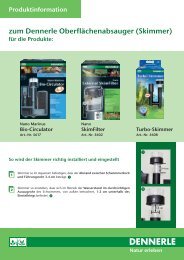
CO2 fertilizer system Exclusive DeLuxe - Dennerle
CO2 fertilizer system Exclusive DeLuxe - Dennerle
CO2 fertilizer system Exclusive DeLuxe - Dennerle

Create successful ePaper yourself
Turn your PDF publications into a flip-book with our unique Google optimized e-Paper software.
3 Die einzelnen Komponenten der CO 2 Dünge-Anlage 104.4 CO 2 Maxi-Flipper anschließen3.1 CO 2 Druckminderer <strong>Exclusive</strong> Flaschendruck-Manometer Arbeitsdruck-Einstellschraube(unter Schutzkappe) Arbeitsdruck-Manometer Präzisions-Getriebe-Nadelventil3.2 CO 2 Nachtabschaltung Netzkabel CO 2 -Zufuhr vom Druckminderer Kontrollleuchte CO 2 -Abgang zum Aquarium Halteplatte CO 2 Special-Rücklaufsicherung3.3 CO 2 Blasenzähler Halterung Verschlusslasche Schlitze für Befestigungmit Haltegurt Longlife-Sauger mitSaugernippeln Blasenzähler Blasenzählrohr CO 2 -Zufuhr vomDruckminderer (Nadelventil) CO 2 -Abgang zum Aquarium Reflektorspange Haltegurt3.4 CO 2 Maxi-Flipper Schlauchanschluss CO 2 -Rohr CO 2 -Auflösungskammer Diffusions-Schlitze CO 2 -Auffangwanne Falschgasentlüftung Longlife-Sauger4 Montage der CO 2 Dünge-Anlage14.1 Druckminderer anschließen• Nadelventil durch Drehen gegen denUhrzeigersinn schließen (falls noch nichtgeschlossen). ACHTUNG: Nur leichtanziehen! • Grüne Schutzkappe von Flaschenventilabziehen.• Druckminderer im Uhrzeigersinn langsamund gerade auf CO 2 -Flasche schraubenund handfest anziehen. Das Fla-2schendruck-Manometer zeigt jetzt ca.60 bar an (bei 20 °C).Hinweis: Beim Auf- oder Abschraubendes Druckminderers kann es kurzetwas "zischen", wie beim Öffnen einerMineralwasserflasche.4 103ACHTUNG: CO 2 -Flasche immer gegen Umfallensichern. Bei der CO 2 -Entnahme muss dieCO 2 -Flasche immer aufrecht stehen!4.2 CO 2 Magnetventil ("CO 2 Nachtabschaltung")mit Rücklaufsicherunganschließen• Halteplatte, mit der Führung nach oben,4an der gewünschten Stelle festschrauben. 3Hinweis: CO 2 Nachtabschaltung nicht aufdünne Holzplatten o.ä. schrauben, dadiese als Resonanzboden wirken undeventuell Brummgeräusche erzeugenkönnen.• Das für die Verbindung von Druckmindererund CO 2 Nachtabschaltung benötig-5te Schlauchstück mit kräftiger Scheregerade abschneiden.• Überwurfmutter vom Nadelventil desDruckminderers abschrauben und auf dasSchlauchende stecken. Schlauch auf denSchlauchanschluss schieben (TIPP: Vorheranfeuchten, dann geht's leichter!) und6mit Überwurfmutter sichern. 4• Das andere Schlauchende an den, vonvorne gesehen, linken Schlauchanschlussder CO 2 Nachtabschaltung anschließen. 5• Nachtabschaltung von oben in dieFührung der Halteplatte schieben. Abb. 6 574.3 Blasenzähler anschließen• Beide Verschlusslaschen öffnen und Blasenzähleraus Halterung nehmen.Wählen Sie eine der folgenden 3Befestigungsmöglichkeiten:(1)Mit dem Haltegurt an der CO 2 -Flasche.• Dazu Haltegurt mit der flauschigen Seite8nach außen, durch die beiden Schlitze derHalterung führen und Halterung an CO 2 -Flasche befestigen.(2)Mit Hilfe von Schrauben an der Wand.• Dazu Sauger und Saugernippel entfernen.(3)Mit den beiden Saugern an der Aquarienscheibe.9• Blasenzähler zu 3 /4 mit Leitungswasser füllen.• Ein Schlauchstück für die Verbindung vonCO 2 Rücklaufsicherung und Blasenzählerabschneiden.• Ein Schlauchende an die Rücklaufsicherunganschließen, das andere an denSchlauchanschluss mit dem Blasenzählrohr.8 Bitte beachten: Der Pfeil auf der Rücklaufsicherung muss immerin Durchflussrichtung zeigen!• Ein Schlauchstück für die Verbindung von Blasenzähler und Maxi-Flipperabschneiden und an den Blasenzähler anschließen.• Blasenzähler in Halterung einklinken und Verschlusslaschen schließen. 95.2 Der pH-Controller im Überblick• Maxi-Flipper mit warmem Leitungswasser abspülen. Keine Reinigungsmittel verwenden! • CO 2 -Zuleitungsschlauch auf Schlauchanschluss stecken. TIPP: Schlauchanschluss vorher anfeuchten,dann lässt sich der Schlauch leichter aufschieben.• Im Aquarium eine Stelle mit guter, aber nicht zu starker Wasserbewegung auswählen.Die Stelle sollte nicht zu hell sein, um möglicher Veralgung vorzubeugen.• CO 2 Maxi-Flipper senkrecht, mit der Auffangwanne nach oben, mindestens 5 cm unter dem Wasserspiegelmit den Saugern befestigen. Pflanzen sollen die Zirkulation des Wassers durch die Schlitze des CO 2 Maxi-Flipper nicht wesentlich beeinträchtigen. 4.5 CO 2 Schlauch befestigen• Der CO 2 -Schlauch kann mit Hilfe der Schlauchhalterungen sauber verlegt und sicher befestigt werden. 5 Der pH-Controller Evolution <strong>DeLuxe</strong>5.1 Sicherheitshinweise für pH-Controller und CO 2 Nachtabschaltung• Nur für Wechselstrom 230 V / 50 Hz.• Nur zur Verwendung in Räumen mit üblicher Verschmutzung.• Der Netzstecker muss nach dem Aufstellen des Gerätes jederzeit zugänglich sein.• Stets für gute Kühlung sorgen, Gerät nicht ab- oder zudecken.• Alle Kabel, die aus dem Aquarium herausführen, und die Netzkabel der Geräte müssen mit einer Tropfschlaufe versehen sein,so dass eventuell an ihnen herunterlaufendes Wasser nicht in die Geräte bzw. die Netzsteckdose gelangen kann.• Vor der Durchführung von Wartungsarbeiten alle Geräte im Aquarium ausschalten.• Wenn die Anschlussleitung des Gerätes beschädigt ist, darf sie ausschließlich durch den Hersteller oder seinenKundendienst ersetzt werden, um Gefährdungen zu vermeiden.• Vor dem Hineinfassen ins Aquarienwasser stets alle im Wasser befindlichen Geräte vom Netz trennen.• Für die Kombination mit einer DENNERLE CO 2 -Nachtabschaltung (Magnetventil) bzw. einem pH-Controller eignen sich nur echteCO 2 -Druckminder<strong>system</strong>e wie z.B. die DENNERLE Druckminderer Compact, Professional und <strong>Exclusive</strong>. Drosselventile arbeiten mit einem viel höherenDruck und dürfen deshalb nicht mit einem Magnetventil bzw. dem pH-Controller kombiniert werden!• Maximale Ausgangsbelastung der Gerätesteckdose beachten (40 W / 0,2 A).• KCL-Lösung und Eichlösungen von Kindern fernhalten. NetzkabelPowerUnitAnschluss für pH-ElektrodeSteckdose für CO 2 -Magnetventil(DENNERLE CO 2 -Nachtabschaltung)SicherungAnschluss für Verbindungskabel zum DisplayHalteplatteDisplayFrontklappepH-Elektrode5
5.3 Die Funktionen im Überblick Nr. Taste / Bauelement Funktion / Bedienung1 pH Anzeige Zeigt den aktuellen pH-Wert im Aquarium. Blinkt, wenn der gemessene Wert mehrals +/– 0,5 vom eingestellten Sollwert abweicht (Alarmfunktion)2 pH Einstellen des gewünschten pH-Werts: Taste drücken, gewünschten pH mit "+" und"–" einstellen3 + Einstellwert erhöhen4 – Einstellwert verringern5 Kontrollleuchte CO 2 -Zugabe Leuchtdiode AN = über das angeschlossene Magnetventil wird CO 2 zugegeben6 Auto Automatische pH-Einstellung: Taste drücken und Karbonathärte des Aquarienwassers mit "+"und "–" eingeben. Der pH-Controller berechnet automatisch den dazu passenden, optimalenpH-Wert (CO 2 -Gehalt) und regelt entsprechend.7 Hys Einstellen der Schaltpunkte (Hysterese) an denen der pH-Controller die CO 2 -Zugabeein bzw. ausschaltet: Taste drücken und gewünschten Wert mit "+" und "–" eingeben.8 pH 4 Eichung der pH-Elektrode: Elektrode in Eichlösung pH 4 stellen und Taste drücken9 pH 7 Eichung der pH-Elektrode: Elektrode in Eichlösung pH 7 stellen und Taste drückenHinweis: Immer erst pH 7, dann pH 4 eichen!10 Kontrollleuchte Leuchtdiode AN = Eichen der pH-Elektrode empfohlen (alle 4 Wochen)Eich-Erinnerung135.4 Montage des pH-Controllers5.4.1 Wandmontage des Displays 13Die Wandhalterung mit dem Pfeil nach oben an der gewünschten Stelle befestigen.Das Display von oben auf die Wandhalterung aufschieben.5.4.2 Verbindungskabel und Magnetventil anschließenDen Stecker des Verbindungskabels vom Display an die entsprechende Buchse der PowerUnit anschließenund mit den beiden Sicherungsschrauben sichern.Das CO 2 -Magnetventil (DENNERLE CO 2 -Nachtabschaltung) mit der Steckdose der PowerUnit verbinden.14 5.4.3 Elektrodenhalter im Aquarium befestigen 14min. 1 cmWählen Sie dazu eine möglichst dunkle Stelle mit guter Wasserbewegung.Die Oberkante des Elektrodenhalters muss sich immer mindestens 1 cm über demWasserspiegel befinden.15165.4.4 pH-Elektrode anschließen 15Stecker der pH-Elektrode an die entsprechende Buchse der Power Unit anschließen.Deckel des Aufbewahrungsfläschchens abschrauben und pH-Elektrode vorsichtig entnehmen.Elektrodenspitze in einem Gefäß mit Aquarienwasser kurz spülen, damit die anhaftendeKCl-Lösung entfernt wird. Elektrode bis zur Eichung (siehe 5.5) in dem Gefäß stehen lassen.5.4.5 pH-Controller einschaltenNetzstecker mit dem 230 Volt-Stromnetz verbinden. Das Gerät ist jetzt betriebsbereit.Bevor der pH-Controller zur Regelung des pH-Wertes im Aquarium eingesetzt werden kann, muss nur nochdie Elektrode geeicht werden. Der pH-Controller zeigt daher in der Anzeige "E" für "Eichen") und dieLeuchtdiode "Eich-Erinnerung" leuchtet. 16Die gelbe Leuchtdiode neben der Taste "pH 7" erinnert daran, dass bei jedem Eichvorgang zuerst immerbei pH 7 und dann bei pH 4 geeicht wird.11 Akustischer Alarm Taste drücken = akustischer Alarm aktiviert (zusätzlich zum optischen Alarm, siehe 1)Taste nochmals drücken = Akustischer Alarm aus12 Dimmer Taste drücken und mit "+" und "–" die Helligkeit der Anzeige der Umgebungshelligkeit anpassen.13 Kontrollleuchte Die Tastensperre schützt vor unbeabsichtigtem Verstellen (Kindersicherung):TastensperreTaste "Dimmer" und "pH" gleichzeitig drücken = Tastensperre aktiviert.Tastenkombination nochmals drücken = Tastensperre aus6 7
5.5 pH-Elektrode eichen5.6 Allgemeine Hinweise zur pH-Elektrode1718pH 7192021pH 45.5.1 Sinn der EichungJedes Messgerät ist nur so genau, wie der Messfühler arbeitet. Die pH-Elektrode ist daher ein entscheidendwichtiges Bauteil des pH-Controllers. Da sich jede pH-Elektrode im Laufe der Zeit etwas verstellen kann, istes für eine gleichbleibend hohe Qualität der Messergebnisse unerlässlich, die pH-Elektrode regelmäßig zueichen.5.5.2 Eichung vorbereiten 17Für optimale Eichwerte sollten die Eichlösungen eine Temperatur von 20-25 °C haben.Eichlösung pH 7, pH 4 und destilliertes Wasser in die entsprechenden Kammern der Eichstation bis zurMarkierung einfüllen.5.5.3 Eichung durchführenDie Comfort-Eichung erlaubt ein schnelles, sicheres und bequemes Eichen der pH-Elektrode:• Elektrode in destilliertem Wasser kurz abspülen.• Elektrode in Eichlösung pH 7 stellen. 18• Ca. 1 Minute warten, damit sich die Elektrode an die Eichlösung anpassen kann.Die Anpassung ist erfolgt, wenn sich der angezeigte Messwert nicht mehr ändert.(Hinweis: Bei der ersten Eichung von pH 7 nach Inbetriebnahme wird noch kein Messwert, sondern"E" angezeigt. Zur Anzeige des Messwerts ist erst eine erfolgreiche Eichung nötig).• Taste "pH 7" drücken: die gelbe Leuchtdiode blinkt, das Gerät eicht jetzt automatisch pH 7, dieAnzeige zeigt "E 7". 19• Ist pH 7 erfolgreich geeicht, erlischt die Leuchtdiode und in der Anzeige erscheint "7.00".Jetzt leuchtet die Leuchtdiode an der Taste "pH 4".• Elektrode aus Eichlösung pH 7 nehmen und in destilliertem Wasser kurz abspülen.Elektrode in Eichlösung pH 4 stellen. 20Warten, bis sich der angezeigte Messwert nicht mehr ändert.• Taste "pH 4" drücken: die gelbe Leuchtdiode blinkt, das Gerät eicht jetzt pH 4, die Anzeige zeigt"E 4". 21• Ist pH 4 erfolgreich geeicht, erlischt die Leuchtdiode und in der Anzeige erscheint "4.00".Die Leuchtdiode "Eich-Erinnerung" erlischt ebenfalls.Damit ist die Eichung abgeschlossen. pH-Elektrode mit etwas destilliertem Wasser abspülen und in denElektrodenhalter im Aquarium hängen. Der Eichvorgang dauert - je nach Zustand der pH-Elektrode -ca. 5-10 Minuten. Gebrauchte Eichlösungen entsorgen. Eichstation mit Leitungswasser ausspülen und mitKüchenpapier trocknen, um Kalkreste zu vermeiden.Der pH-Controller ist nun einsatzbereit.Die Anzeige zeigt den aktuellen pH-Wert im Aquarium.2223min. 1 cm24255.6.1 Behandlung und Aufbewahrung• pH-Elektrode immer sorgfältig behandeln. Elektrodenkabel nicht knicken.• pH-Elektrode nie austrocknen lassen.• Versehentlich eingetrocknete Elektroden kann man unter Umständen wieder funktionsfähig machen, indem man sie für 24 Std. in KCl-Lösung stellt.• Bei pH-Elektroden, die längere Zeit nicht benutzt werden, Aufbewahrungsfläschchen mit KCl-Lösung(Best.-Nr. 1448) füllen, auf Elektrodenspitze stecken und Deckel festschrauben. 22• Die Elektrode nicht komplett unter Wasser tauchen. Elektrodenkappe und Kabelanschluss müssen sichimmer mindestens 1 cm oberhalb des Wasserspiegels befinden. 23• Elektrode an einer möglichst dunklen Stelle im Aquarium befestigen, damit die Elektrode nicht veralgenkann. Veralgte Elektrodenspitzen können sich nachteilig auf die Messgenauigkeit auswirken.• Elektrodenkabel nicht über längere Distanzen zusammen mit anderen Stromkabeln verlegen.So vermeiden Sie Beeinflussungen der Messergebnisse durch andere Stromkreise.• ACHTUNG: Ist die pH-Elektrode nicht im Aquarienwasser, misst das Gerät "falsch" und regelt entsprechend- Gefahr für Fische! Deshalb regelmäßig den Wasserstand kontrollieren!• Ist die Elektrodenspitze verschmutzt, kann die kugelige Messspitze sehr vorsichtig mit einem weichenTuch gereinigt werden - nur abtupfen, nicht reiben! Anschließend für 12 Stunden in KCl-Lösung stellen.Danach abspülen und eichen.5.6.2 Lebensdauer der pH-ElektrodeAlle pH-Elektroden sind Verschleißteile und verbrauchen sich mit der Zeit. Sie haben im Dauereinsatz eineübliche Lebensdauer von 12 bis 36 Monaten, im Durchschnitt ca. 24 Monate.Der Verschleiß ist individuell unterschiedlich und hängt ab von Wasserhärte, Säuregehalt des Wassers,Algenbewuchs, allgemeiner Verschmutzung, mechanischer Beanspruchung, Pflege, usw.5.6.3 pH-EichlösungenDie Genauigkeit der Eichung hängt entscheidend von der Qualität der verwendeten Eichlösungenab. Wir empfehlen original DENNERLE Eichlösungen. 24Verwenden Sie immer frische Eichlösungen und eichen Sie die Elektroden in separaten, sauberen Gefäßen,am besten in der DENNERLE Eichstation. Schütten Sie die einmal benutzte Eichlösungen weg. Nicht in denVorratsflaschen eichen - durch an der pH-Elektrode haftendes Wasser können die Eichlösungen verändertwerden.5.7 pH-Wert messen und einstellen5.7.1 pH-Wert im AquariumIm Normalbetrieb erscheint in der Anzeige der aktuelle pH-Wert, der im Aquarium gemessen wird(= Istwert).5.7.2 Gewünschten pH-Wert einstellenTaste "pH" drücken: Die grüne Leuchtdiode neben der Taste blinkt, die Anzeige zeigt den momentanprogrammierten pH-Wert.• Mit den Tasten "+" und "–" den gewünschten pH eingeben (Sollwert). 25• Wird 3 sec. keine Taste betätigt, übernimmt der pH-Controller den eingegebenen Wert. In der Anzeigeerscheint wieder der Istwert im Aquarium, die grüne Leuchtdiode leuchtet permanent, das Gerät regeltentsprechend.89
5.7.3 Kontrolle des eingestellten pH-Werts• Taste "pH" drücken: Die grüne Leuchtdiode neben der Taste blinkt, die Anzeige zeigt den eingestelltenpH-Wert.• Nach 3 sec. erscheint in der Anzeige wieder der Istwert, die grüne Leuchtdiode leuchtet permanent,das Gerät regelt normal weiter.5.8 Regelung im NormalbetriebTabelle1: Zusammenhang zwischen pH-Wert, CO 2 -Gehalt und Karbonathärte26Beispiel 1: Aktueller pH-Wert im Aquarium = 7,5. Sie stellen pH 6,8 ein.Die grüne Kontrollleuchte ”CO 2 -Zugabe“ leuchtet. 26 Das angeschlossene CO 2 -Magnetventil ist geöffnetund es wird CO 2 zugegeben (entsprechend der vorher am Druckminderer-Nadelventil eingestelltenCO 2 -Blasen pro Minute). Die CO 2 -Zugabe erfolgt so lange, bis im Aquarium ein pH-Wert von 6,7* erreichtwird, dann schaltet der pH-Controller das Magnetventil ab.Beispiel 2: Aktueller pH-Wert im Aquarium = 6,5. Sie haben 6,8 eingestellt.Die Kontrollleuchte ”CO 2 -Zugabe“ leuchtet nicht. Es wird kein CO 2 zugegeben. Erst wenn der pH-Wert imAquarium über 6,9* steigt, schaltet der pH-Controller die CO 2 -Zugabe wieder ein.*Bei vorgewählten Schaltpunkten von 0,1 (Werkseinstellung), siehe auch Punkt 5.10.25.9 pH-Wert, CO 2 -Gehalt und CO 2 -Zugabemenge5.9.1 Warum man mit CO 2 den pH-Wert einstellen kannCO 2 löst sich im Wasser zum Teil als Kohlensäure und senkt dadurch den pH-Wert. Das Ausmaß dieserpH-Senkung wird maßgeblich durch die Karbonathärte bestimmt. Die Karbonathärte wirkt als Puffer unddamit einer pH-Senkung entgegen.CO 2 -Gehalt, Karbonathärte und pH stehen immer in einem genau definierten Verhältnis zueinander(siehe Tabelle). Sind zwei Werte bekannt, kann man den dritten berechnen.5.9.2 Die richtige CO 2 -Menge und den richtigen pH einstellenDENNERLE empfiehlt für prächtigen Pflanzenwuchs einen CO 2 -Gehalt im Aquarium zwischen15 und 30 mg/l, ideal sind 20 bis 25 mg/l.• Messen Sie Karbonathärte des Aquarienwassers (Tests im Fachhandel).• Lesen Sie in der Tabelle den zum gewünschten CO 2 -Gehalt passenden pH-Wert ab. Diesen pH-Wertam pH-Controller eingeben.Beispiel: Karbonathärte 4 °d, empfohlener pH 6,8.Wichtiger Hinweis: Stellen Sie nur solche pH-Werte bzw. CO 2 -Gehalte ein, die entsprechend derKarbonathärte für Fische verträglich sind. Wenn Sie z.B. für bestimmte Fischarten einen pH von6,5 einstellen wollen, dann solte die Karbonathärte auf 2-3 °d gesenkt werden. Der CO 2 -Gehaltsollte langfristig nicht höher als 40 mg/l sein. Beachten Sie dazu auch die einschlägige Fachliteraturoder fragen Sie Ihren Zoofachhändler!5.9.3 Die benötigte CO 2 -Zugabemenge einstellenDie für den gewünschten pH erforderliche CO 2 -Zugabemenge (CO 2 -Blasen/Minute) hängt vonverschiedenen Faktoren ab, z.B. Bepflanzung, Wasserbewegung, Oberfläche/Volumen-Verhältnis, usw.Deshalb ist es erforderlich, die CO 2 -Zugabemenge für jedes Aquarium individuell zu ermitteln:• Faustregel für die Grundeinstellung: Beginnen Sie mit ca. 10 Blasen pro Minute pro 100 lAquarienwasser, d.h. für ein 200 l-Aquarium z.B. mit 2 x 10 = 20 Blasen pro Minute.• Nadelventil langsam und zunächst nur wenig öffnen, bis im Blasenzähler die ersten Blasen austreten.• Gewünschte Blasenzahl am Nadelventil einstellen:- im Uhrzeigersinn drehen: Blasenzahl erhöhen- gegen den Uhrzeigersinn drehen: Blasenzahl verringern. 27Bitte beachten: Die Blasenzahl reagiert zeitverzögert auf Änderungen am Nadelventil. Blaseneinstellungdaher behutsam durchführen.• Kontrollieren Sie nach 1 Tag mit dem pH-Controller, ob damit der gewünschte pH erreicht wird und dasGerät korrekt regeln kann, d.h. das angeschlossene Magnetventil zeitweise abgeschaltet wird.• Wenn nicht, sollte die Blasenzahl auf ca. 15 Blasen pro Minute pro 100 l Aquarienwasser erhöht werden.Nach 1 Tag wieder kontrollieren. Blasenzahl, wenn nötig, in jeweils kleinen Schritten weitererhöhen, bis der gewünschte pH erreicht wird.Bitte beachten: Je stärker die Wasseroberfläche bewegt wird (z.B. durch Filter, zusätzliche Belüftung),desto mehr CO 2 wird wieder aus dem Aquarium ausgetrieben.• Blasenzahl in den ersten Tagen öfter kontrollieren und gegebenenfalls nachregulieren. Später genügtes im allgemeinen, die Blasenzahl einmal pro Woche zu kontrollieren.5.10 Sonderfunktionen5.10.1 Automatische pH-EinstellungMit der Funktion "Auto" lässt sich direkt der optimale CO 2 -Gehalt (ca. 20 mg/l) einstellen, ohne in derTabelle nachschauen zu müssen:• Taste "Auto" drücken: Die grüne Leuchtdiode blinkt, in der Anzeige erscheint der zuletzt eingestellteWert 28 (Werkseinstellung: 04). Mit "+" und "–" die im Aquarium gemessene Karbonathärte eingeben.• Nach 3 sec. ohne Tastenbetätigung wird dieser Wert übernommen. Der pH-Controller berechnet automatischden dazu exakt passenden pH-Wert und regelt entsprechend. Die Leuchtdiode leuchtet permanent.• Überprüfung des eingestellten pH-Werts: Taste "pH" drücken: Der Sollwert erscheint für 3 sec. in der Anzeige.Beispiel: eingegebene Karbonathärte 6 °d.Der pH-Controller stellt automatisch pH 7,0 ein (= 20 mg/l CO 2 ).• Funktion "Auto" ausschalten: Taste "pH" drücken und, während die grüne Leuchtdiode blinkt,mit "+" und "–" neuen Sollwert eingeben.Einstellbereich: 1 - 20 °d Karbonathärte.10 112728-+
5.10.2 Einstellen der SchaltpunkteMit der Funktion "Hys" lassen sich die Schaltpunkte (Hysterese) einstellen, an denen der pH-Controller dieCO 2 -Zugabe ein bzw. ausschaltet.Beispiel 1: Schaltpunkte 0,1 - pH Sollwert 6,8Der pH-Controller schaltet die CO 2 -Zugabe ein, wenn der pH-Wert im Aquarium über 6,9 steigt und aus,wenn er unter 6,7 sinkt.335.13.2 Akustischer AlarmDer akustische Alarm kann zusätzlich zum optischen Alarm aktiviert werden. Das ist z.B. dann sinnvoll,wenn der pH-Controller im Aquarien-Unterschrank installiert ist:• Akustischen Alarm aktivieren: Taste drücken, Leuchtdiode leuchtet 33• Akustischen Alarm ausschalten: Taste nochmals drücken, Leuchtdiode aus293031Beispiel 2: Schaltpunkte 0,05 - pH Sollwert 6,8Der pH-Controller schaltet die CO 2 -Zugabe ein, wenn der pH-Wert im Aquarium über 6,85 steigt und aus,wenn er unter 6,75 sinkt.• Taste "Hys" drücken: In der Anzeige erscheint der aktuell eingestellte Wert. 29• Mit "+" und "–" den gewünschten Wert einstellen.• Nach 3 sec. ohne Tastenbetätigung wird dieser Wert übernommen. Der pH-Controller regelt entsprechend.Mögliche Werte: 0,01 – 0,05 – 0,1 – 0,15 – 0,2. Werkseinstellung: 0,1 (empfohlen).5.11 Automatische Eich-ErinnerungDie gelbe Leuchtdiode "Eich-Erinnerung" erinnert automatisch alle 4 Wochen daran, dass die Elektrode wiedergeeicht werden sollte (Gleichzeitig leuchtet die Leuchtdiode pH 7). 30Zur Vorgehensweise siehe Punkt 5.5Die Eich-Erinnerung hat keine Einfluss auf die normale Mess- und Regelfunktion des pH-Controllers.5.12 Zusätzliches EichenDie Elektrode kann jederzeit zusätzlich geeicht werden, auch wenn die Eich-Erinnerung nicht aktiv ist,dazu:• Taste "pH 7" drücken: Die Leuchtdiode "pH 7" und die Leuchtdiode "Eich-Erinnerung" leuchten. 31• Taste "pH 7" (innerhalb von 1 Minute) nochmals drücken: Das Gerät geht vom normalen Regelmodusin den Eichmodus über: Die Leuchtdiode "pH" erlischt, das angeschlossene Magnetventil wird abgeschaltet.• Dann weiter wie unter Punkt 5Insbesondere bei erster Inbetriebnahme des pH-Controllers oder Anschließen einer neuenpH-Elektrode sollte die Elektrode nach 1 Woche zusätzlich geeicht werden.34355.14 Komfortfunktionen5.14.1 Anzeige dimmenDie Anzeige und alle Leuchtdioden können gedimmt werden, um sie ideal an dieUmgebungshelligkeit anzupassen:• Taste "Dimmer" drücken und mit "+" und "–" die gewünschte Helligkeit einstellen.• Nach 3 sec. ohne Tastenbetätigung wird dieser Wert übernommen.Mögliche Dimmwerte: 1-85.14.2 Tastensperre (Kindersicherung)Die Tastensperre schützt vor unbeabsichtigtem Verstellen der programmierten Sollwerte:• Tastensperre aktivieren: Taste "Dimmer" und "pH" gleichzeitig drücken, Leuchtdiode "Tastensperre"leuchtet. 35• Tastensperre ausschalten: Tastenkombination nochmals drücken, Leuchtdiode aus.Hinweis: Wird während aktivierter Tastensperre eine beliebige Taste gedrückt, erscheint in der Anzeige"SAF" (für engl. SAFE = gesichert). Nur der programmierte pH-Sollwert kann mit der Taste "pH"abgefragt werden.345.13 Warnanzeigen5.13.1 Die Anzeige blinktDie Anzeige blinkt, wenn der pH-Wert im Aquarium mehr als + 0,5 oder – 0,5 vomeingestellten Sollwert abweicht. 32 Dann sofort das System überprüfen:• Ist noch CO 2 in der Vorratsflasche?• Ist die Blasenzahl/Minute richtig eingestellt?• Bei zu hohem pH-Wert: Ist die Blasenzahl/Minute eventuell zu gering?• Bei zu niedrigem pH-Wert: Ist die Blasenzahl/Minute eventuell zu groß?• Funktioniert das Magnetventil?• Ist die pH-Elektrode korrekt im Aquarium befestigt?3212 13
6 Der CO 2 Langzeittest Correct6.1 FunktionsweiseDer CO 2 Langzeittest erlaubt eine zusätzliche, optische Kontrolle derCO 2 -Menge direkt im Aquarium.Je nach CO 2 -Gehalt reagiert der CO 2 Special-Indicator mit einerFarbänderung: von • Blau = zu wenig CO 2 über • Grün = CO 2 optimalnach • Gelb = zu viel CO 2 .An der Farbvergleichs-Skala kann man die CO 2 -Menge im Aquariumdirekt in Milligramm pro Liter ablesen.6.2 Was ist was363738 Testbehälter-Unterteil Testbehälter-Oberteil Reflektionskegel O-Ringe Haltespange6.3 Inbetriebnahme Halterung Longlife-Sauger CO 2 Special-Indicator Farbvergleichs-Skala• Testbehälter aus Haltespange nehmen.Testbehälter-Oberteil abziehen. 36• Eine Ampulle mit CO 2 Special-Indicatornehmen und sicherstellen, dass sich keinIndikator im Ampullenhals befindet!Dazu Indikator in der Ampulle herunterschütteln(wie bei einem Fieberthermometer).Ampulle durch Abdrehender Verschlusslasche öffnen. 37• Gesamten Ampullen-Inhalt in das Testbehälter-Oberteiltropfen. 38• Gehäuse-Unterteil samt Reflektorkegel indas Oberteil stecken. Auf richtigen Sitzder O-Ringe achten! 39• Testbehälter vorsichtig umdrehen und inHaltespange einsetzen. 40• CO 2 Langzeittest mit Hilfe des Saugersan einer gut sichtbaren Stelle mit leichterWasserströmung senkrecht im Aquariumbefestigen. 413940414243• Farbvergleichs-Skala außen auf dieAquarienscheibe kleben. 42Bitte beachten: Weil das CO 2 eine gewisseZeit braucht, um in den Indikator hinein zudiffundieren, reagiert die Farbanzeige aufÄnderungen des CO 2 -Gehaltes jeweils miteinigen Stunden Verzögerung.6.4 Verwendung als pHLangzeittestMit dem CO 2 Langzeittest kann man gleichzeitigauch den pH-Wert im Aquarium überwachen(Unter der Voraussetzung, dasssich keine anderen, maßgeblich pH-beeinflussendeSubstan-zen im Wasser befinden,z.B. größere Mengen Huminsäurenoder Nitrat, pH Plus-, pH Minus-Präparateusw.):• Karbonathärte des Aquarienwassers messen.• Entsprechende Farbvergleichs-Skala außenan die Aquarienscheibe kleben. 43An der Farbskala kann man nun direkt denpH-Wert des Aquarienwassers ablesen.Karbonathärte regelmäßig messen undimmer entsprechende Farbskala verwenden.6.5 Besondere Hinweise• CO 2 Langzeittest und Indikator von Kindern fernhalten!• Der CO 2 Special-Indicator ist ungefährlich und frei von chemischen Lösungsmitteln.Trotzdem längeren Hautkontakt und Augenkontakt vermeiden.• Der Indikator kann eventuell färben – Kontakt mit Kleidung, Teppichen,Holz, usw. vermeiden.• Versehentlich ins Aquarienwasser gelangter Indikator ist für alleFische, Pflanzen und andere Aquarienbewohner harmlos.• Der CO 2 Special-Indicator ist unter Schutzatmosphäre abgefüllt.Füllhöhe technisch bedingt.• CO 2 Special-Indicator vor Sonne, Hitze und Frost schützen. Die Ampullenstets lichtgeschützt lagern.7. Pflege, Wartung und besondere Hinweise7.1 CO 2 Dünge-Anlage7.1.1 CO 2 -Flasche auswechseln• Nadelventil schließen. Achtung: Nur leicht anziehen!• Druckminderer von CO 2 -Flasche abschrauben und auf neueCO 2 -Flasche aufschrauben.• Blasenzahl neu einstellen.Neue CO 2 Einweg-Vorratsflaschen erhalten Sie im Fachhandel.TIPP: Halten Sie immer eine neue CO 2 -Flasche in Reserve. Dann kommenSie nicht in Schwierigkeiten, wenn Ihnen - etwa am Wochenende - dasCO 2 ausgeht.Bei längerem Nichtgebrauch sollte der Druckminderer abgeschraubtwerden. Das Ventil der noch gefüllten CO 2 Einweg-Vorratsflascheschließt automatisch.7.1.2 Arbeitsdruck am Druckminderer nachstellen44Der Arbeitsdruck des Druckminderers<strong>Exclusive</strong> ist werksseitig auf ca. 1 bar eingestellt.Insbesondere in den ersten Wochennach Inbetriebnahme kann sich derArbeitsdruck noch etwas ändern, da sich dieDichtungen setzen.Arbeitsdruck nachstellen:44• Schutzkappe abnehmen• Erhöhen: Arbeitsdruck-Einstellschraube mit geeignetem Schraubenziehergegen den Uhrzeigersinn drehen.Verringern: Arbeitsdruck-Einstellschraube im Uhrzeigersinn drehen.7.1.3 Dichtung im Druckminderer ersetzenDie selbstsichernde, wartungsfreie Longlife-45Dichtung im Anschlussstutzen desDruckminderers hält normalerweise vieleJahre. Falls der Anschluss auch nach mehrmaligem,geraden (!) Aufschrauben desDruckminderers nicht dicht wird, ist dieDichtung vermutlich verschlissen und sollteausgetauscht werden:• Dazu mit einem kleinen Schraubenzieher o.ä. seitlich hinter die Dichtungfassen und Dichtung vorsichtig heraushebeln. 45Achten Sie darauf, das Anschlussgewinde, den Druckstift und dieDichtfläche nicht zu beschädigen!Stellen Sie unbedingt sicher, dass keine Fremdkörper (Staub,Schmutzpartikel, Metallspänchen, usw.) in die Druckminderer-Öffnunggelangen!• Anschlussstutzen säubern (ausblasen).• Neue Dichtung mit geeignetem, nicht-metallischen Gegenstand vorsichtigeindrücken. Dichtung und Anschlussstutzen dabei nicht beschädigen.Auf richtigen Sitz achten.7.1.4 CO 2 -Rücklaufsicherung prüfenDie Rücklaufsicherung schützt Ihren wertvollen Druckminderer vor Korrosiondurch zurücklaufendes Wasser. Sie übt ihre Funktion sehr lange und zuverlässigaus. Da sich jedoch im Laufe der Zeit Schmutz-, Farb- und Metallteilchenauf den Dichtflächen absetzen können, sollte man die Rücklaufsicherung spätestensalle 2 Jahre überprüfen und eventuell austauschen.Prüfung:• Nadelventil am CO 2 -Druckminderer schließen.• Nach 24 Stunden Überwurfmutter an der Seite der Rücklaufsicherung,die zum Druckminderer zeigt, abschrauben.• CO 2 -Schlauch abziehen und überprüfen, ob Wasser eingedrungen ist.Wenn JA: Rücklaufsicherung austauschen. Wenn NEIN: Schlauch wiederan Rücklaufsicherung anschließen.• Blasenzahl neu einstellen.Keine Sorge: 24 Std. ohne CO 2 -Versorgung wird von einem gut funktionierendenAquarium normalerweise problemlos verkraftet.Wichtiger Hinweis: Benutzen Sie ausschließlich Rücklaufsicherungen, diefür den Betrieb mit CO 2 ausgelegt sind, wie die DENNERLE CO 2Special-Rücklaufsicherung. Normale Luft-Rücklaufsicherungen könnendurch CO 2 bereits innerhalb kurzer Zeit – meist unbemerkt - versprödenund werden dann undicht.7.2 CO 2 Langzeittest7.2.1 CO 2 Special-Indicator austauschenDer Indikator ist, wie die meisten Farbstoffe, einer gewissen Alterungdurch photochemische Prozesse unterworfen. Um stets eine möglichstschnelle und exakte Farbreaktion zu gewährleisten, empfehlen wir deshalb,den Testbehälter alle 4 Wochen mit frischem CO 2 Special-Indicatorzu füllen.Dazu Testbehälter öffnen und alten Indikator wegschütten (Hauskanalisation).Testbehälter mit Leitungswasser ausspülen und vor dem Neubefüllenmit einem Küchentuch o.ä. trocknen.7.2.2 CO 2 Langzeittest reinigenMit warmem Wasser und weichem Schwamm. Keine Reinigungsmittelverwenden!Der Testbehälter kann zur Reinigung zerlegt werden. Die beiden O-Ringevor dem Zusammenbau eventuell leicht (!) mit Vaseline einfetten(Apotheke, Drogerie).ACHTUNG: Setzen Sie keine anderen Schmiermittel ein (z.B. Spülmittel,Handcreme, usw.), da sie die Farbanzeige verfälschen können.7.3 CO 2 Maxi-Flipper7.3.1 Funktionsweise und EinlaufzeitDer DENNERLE CO 2 Maxi-Flipper ist ein modernes, hoch effektives CO 2Zugabegerät. Damit wird das wertvolle CO 2 bestmöglich benutzt.Das CO 2 tritt unten im Maxi-Flipper an der Öffnung des CO 2 -Rohres aus.Die CO 2 -Blasen laufen nun langsam im Maxi-Flipper hoch. Dabei löst sichdas CO 2 im Aquarienwasser. 46Gleichzeitig dringen andere, natürlicherweise im 46Aquarienwasser gelöste Gase in die CO 2 -Blasenein. Diese sogenannten Falschgase sind derGrund dafür, dass die Blasen nach oben hin zwarkleiner werden, sich jedoch nicht vollständig auflösen.Die Falschgase sind deutlich leichter alsdas relativ schwere CO 2 und sammeln sich deshalbin der Auffangwanne oben. Hier werden sieregelmäßig und automatisch durch die speziellentwickelte Falschgasentlüftung abgeführt.Die Einlaufzeit des Maxi-Flipper beträgt ca. 2 Tage.Anfangs vereinigen sich die einzelnen CO 2 -Blasenzu größeren Blasen. Schon innerhalb kurzer Zeitbildet sich jedoch im Maxi-Flipper eine biologischeOberfläche aus Mikroorganismen. Sie sorgt dafür,daß die einzelnen CO 2 -Blasen bis zur Auffangwannedurchlaufen.14 15+–
47484950517.3.2 CO 2 Maxi-Flipper reinigen• CO 2 Maxi-Flipper aus Aquariumherausnehmen.• CO 2 Auffangwanne gerade nach obenabziehen. 47• CO 2 Maxi-Flipper flach in die linke Handlegen, so dass die Sauger nach rechtszeigen. Die offene Seite (Sitz derAuffangwanne) zeigt nach oben.• Vordere Seitenwand des Maxi-Flipperca. 2 cm nach oben verschieben. 48• Seitenwand herausklappen. 49• CO 2 -Rohr herausnehmen,nicht herausziehen.• Alle Teile des CO 2 Flipper mit warmemWasser und weichem Schwamm reinigen.Keine Reinigungsmittel verwenden.• Flipper in umgekehrter Reihenfolge wieder zusammenbauen.Achtung: CO 2 -Rohr wieder so in Seitenwandeinlegen, dass sich dasEnde am unteren Anschlag befindet. 507.4 Hinweis zum CO 2 -SchlauchDer CO 2 Special-Schlauch Softflex istselbstdichtend und selbstsicherndund bietet so ein Höchstmaß anSicherheit. Zum Entfernen den Schlauchimmer abhebeln, NICHT abziehen! 51TIPP: Durch Schläuche, die nicht CO 2 -dicht sind ("Luftschläuche"), könnentäglich große Mengen wertvolles CO 2verloren gehen. Benutzen Sie deshalbimmer geeignete CO 2 -Schläuche wieden DENNERLECO 2 Special-Schlauch Softflex.7.5 pH-Controller7.5.1 Austausch der SicherungWenn sich das angeschlossene Magnetventil nicht öffnet, obwohl dieLeuchtdiode anzeigt, dass es eingeschaltet ist, dann ist entweder dasMagnetventil oder die Sicherung defekt.• Sicherung prüfen: Normale Tischlampe (max. 40 W) an dieSteckdose der Power Unit anschließen. Sollwert so niedrig einstellen,dass das Magnetventil eingeschaltet wird. Leuchtet die Lampe nicht,ist die Sicherung defekt.• Sicherung austauschen: pH-Controller vom Stromnetz trennen.Sicherungshalter herausschrauben und defekte Sicherung entnehmen.Neue Sicherung gleichen Typs (Elektrofachhandel) einsetzen undSicherungshalter wieder einschrauben.7.5.2 Was passiert bei Stromausfall?Bei einem Stromausfall bleiben alle einprogrammierten Sollwerte undFunktionen im internen Langzeitspeicher erhalten. Sobald der pHController wieder mit Strom versorgt wird, regelt er den pH-Wert imAquarium automatisch wieder auf den eingestellten Wert.7.6 Reinigung der GeräteoberflächenMit feuchtem Tuch und mildem Reinigungsmittel. Keine scharfenReinigungsmittel oder Lösungsmittel verwenden!8 Was tun wenn... – Fehler selber finden8.1 CO 2 -DüngeanlageFehlerAn Schraubverbindungvon Druckminderer undCO 2 -Flasche ist ein leisesZischen zu hören.Keine Blasen mehr amCO 2 Maxi--Flipper.CO 2 -Blasen kommenaus Rohr, steigen abernicht auf oder bleibennach der ersten Treppestehen.Blasen taumeln hin undher, steigen aber nichtauf.Aus Auffangwanne vonMaxi-Flipper entweichtseitlich Gas.CO 2 -Blasen steigennicht mehr ungehindertan Treppen vonMaxi-Flipper auf.UrsacheDruckminderer istschräg oder nicht festgenug aufgeschraubt.Dichtung im Anschlussstutzendes Druckminderersdefekt.CO 2 -Flasche leer.Nadelventil geschlossen.Schlauchverbindungenundicht.Arbeitsdruck zu niedrig.Maxi-Flipper ist nichtsenkrecht montiert.Maxi-Flipper befindetsich noch in derEinlaufphase.Wasserbewegung zustark.Maxi-Flipper ist nichtsenkrecht montiert.Falschgasentlüftungder CO 2 -Auffangwanneverschmutzt.CO 2 -Auffangwanne istschief aufgesteckt.Algenbildung, kleineSchnecken oder Mulmansammlungin Maxi-Flipper.BehebungDruckminderer abschrauben und wiedergerade aufschrauben.Handfest anziehen.Neue Dichtung einbauen(siehe oben).CO 2 -Flasche auswechseln.Nadelventil öffnen.Schlauchverbindung prüfenund ggf. erneuern.Arbeitsdruck auf ca. 1bar einstellen.Maxi-Flipper senkrechtmontieren.Ende der Einlaufphaseabwarten.Wasserbewegung einschränkenoder Maxi-Flipper an ruhigererStelle anbringen.Maxi-Flipper senkrechtmontieren.Maxi-Flipper reinigen.Auffangwanne abziehenund richtig aufstecken.Maxi-Flipper reinigen.FehlerDer pH-Wert im Aquariumerreicht nicht deneingestellten SollwertUrsacheCO 2 -Zugabe zu gering8.2 CO 2 -NachtabschaltungFehlerAn Schlauchverbindungvon Nachtabschaltungoder Rücklaufsicherungist ein leises Zischen zuhören.Kontrollleuchte AUS,aber CO 2 -Zugabe.UrsacheSchlauchverbindung undicht.Kontrollleuchte AN, CO 2 -Flasche leer.aber keine CO 2 -Zugabe.Flaschenventil oderNadelventil am Druckminderergeschlossen.8.3 pH-ControllerFehlerUrsacheKeine Eichung möglichoder Anzeigezeigt "Err"Magnetventil klemmt.Magnetventil klemmtoder Kontrollleuchtedefekt.Die Elektrode steht inEichlösung pH 7 (pH4), man hat aber Taste"pH 4" ("pH 7")gedrücktEichlösungen verdorben/zualtpH-ElektrodeverschmutztpH-Elektrodeverbraucht oderdefektBehebungCO 2 -Blasenzahlschrittweise um5 Blasen/100 l AquarienwassererhöhenBehebungVom Schlauchende ca.2 cm gerade abschneiden,Schlauch bis zumAnschlag aufschiebenund mit Überwurfmuttersichern.CO 2 -Flasche wechseln.Flaschenventil bzw.Nadelventil öffnen.Gerät an Kundenserviceschicken.Gerät an Kundenserviceschicken.BehebungEichvorgang wiederholen,beginnend mitpH 7Frische Eichlösungenbenutzen,Eichung wiederholenpH-Elektrode reinigenNeue pH-Elektrodeanschließen und eichen;nach 1 Wochezusätzlich eichenFehlerAnzeige "F 01"Keine CO 2 -Zugabe,obwohl Kontrol-leuchteCO 2 -Zugabe ANKeine AnzeigeUrsacheElektrodenkabelnicht richtig angeschlossenElektrodenkabel defektMesswert außerhalbdes MessbereichCO 2 -Versorgung gestörtMagnetventil nichtrichtig angeschlossenoder defektSicherung defektVerbindungskabelnicht angeschlossenGerät defektBehebungSteckverbindungüberprüfenElektrode ersetzenCO 2 -System überprüfen(z.B. Flascheleer? Nadelventilgeschlossen?Schlauchanschlüsseundicht?)Anschluss prüfen,Magnetventil ggf. erneuernsiehe Punkt 7.5.1Verbindungskabelrichtig anschließenund mit SicherungsschraubenbefestigenGerät zur Überprüfungan denDENNERLE Kundendiensteinsenden16 17
9 Technische Daten9.1 CO 2 Einweg-VorratsflascheUN 1013 Kohlendioxid, 2.2, GGVSE/ADR/RID/EINECS 2046 969Nach TRG 303. TÜV-Prüfnummer: 057478/85. Inhalt: max. 500 g CO 2 .Tara: 1,16 kg. Volumen: 930 ccm. Druck 36 bar (0 °C). Prüfdruck: 165bar. Selbstschließendes Flaschenventil. Anschlussgewinde M 10 x 1,25.9.2 Druckminderer <strong>Exclusive</strong> für Comfort-LineFlaschendruck-Manometer: 0 - 250 bar. Arbeitsdruck-Manometer: 0 - 6bar. Arbeitsdruck einstellbar. Anschluss für Schlauch 4/6 mm. Getriebe-Nadelventil mit Edelstahlnadel und Feinstgewinde. SelbstschließendesÜberdruckventil.Hinweis: Der CO 2 -Druckminderer <strong>Exclusive</strong> wurde speziell für die DEN-NERLE CO 2 Einweg-Vorratsflaschen der Comfort-Line entwickelt und darfnur zusammen mit diesen benutzt werden. Der Betrieb mit CO 2 -Mehrwegflaschen über einen Adapter ist NICHT zulässig.9.3 CO 2 Nachtabschaltung ComfortNetzspannung/Netzfrequenz : 230 V~ / 50 HzLeistungsaufnahme:2,4 WattMax. zulässiger Druck:7 barLänge des Netzkabels:2 mSchaltzustände: unter Spannung = offen (Kontrollleuchte AN),spannungslos = geschlossenIPX4 – SpritzwassergeschütztCE9.4 pH-Controller Evolution <strong>DeLuxe</strong>Netzspannung/Netzfrequenz : 230 V~ / 50 HzLeistungsaufnahme:42 WattAusgang für Magnetventil: 230V~, max. 40 W / 0,2 ATLänge Netzstromkabel:3 mLänge Verbindungskabel: 3 mLänge Elektrodenkabel:3 mElektrodenanschluss:BNCAnschluss Steuerkabel:SUB-d 9poligMessbereich: pH 3 - 9Einstellbereich: pH 5,0 - pH 8,8Karbonathärtebereichfür automatische pH-Einstellung: 1-20 °dEinstellbare Hysterese: 0,01 – 0,05 – 0,1 – 0,15 - 0,2IPX4 – SpritzwassergeschütztCE10 Ersatzteile und nützliches Zubehör(beim Fachhandel erhältlich)3013 CO 2 Einweg-Vorratsflasche 500 g3016 Comfort-Line CO 2 Druckminderer <strong>Exclusive</strong>3029 Dichtung für Comfort-Line Druckminderer, 2 Stück3043 Longlife-Sauger, grün, 2 Stück3042 Longlife-Sauger, schwarz, 2 Stück1484 Lecksuchspray3061 CO 2 Special-Schlauch Softflex, 5 m3050 CO 2 Blasenzähler Exact3053 CO 2 Special-Rücklaufsicherung3041 CO 2 Special-Indicator, 5 Ampullen3080 CO 2 Nachtabschaltung Comfort3017 pH-Controller Evolution Deluxe3089 pH-Elektrode1445 Eichlösung pH 4, 50 ml1446 Eichlösung pH 7, 50 ml1447 Destilliertes Wasser, 250 ml1448 KCl-Lösung, 50 ml3091 Eich-Station3094 pH-Elektrodenhalter11 GarantiebestimmungenGarantiezeit: 36 MonateVerschleißteile (z.B. pH-Elektrode): 12 MonateIn der Garantiezeit erhalten Sie kostenlosen Ersatz, bzw. kostenloseReparatur defekter Teile. Voraussetzung: Ordnungsgemäßer Gebrauch,Einsendung der ausgefüllten Garantiekarte und der Kassenquittung.Die Geräte dürfen innerhalb der Garantiezeit ausschließlich durch denDENNERLE Kundendienst geöffnet werden, andernfalls erlischt dieGewährleistung.Weitere Ansprüche über den Wert der Geräte hinaus, insbesondere z.B.Schäden an Fischen bzw. Pflanzen können nicht anerkannt werden.Änderungen, insbesondere solche des technischen Fortschritts,vorbehalten.Lassen Sie sich vom Fachhandel über das DENNERLE AquarienpflanzenundZubehör-Programm beraten oder fordern Sie die kostenlosenDENNERLE Profi-Tipps an!DENNERLE Profi-Tipps erhalten Sie auch beim Fachhandel und im Internetunter www.dennerle.de!Sommaire1 Fonctionnement de l’installation de fumure CO 2 <strong>Exclusive</strong> <strong>DeLuxe</strong> . . . . . . . . . . . . . . . . . . . . . . . . . . . . . . . . . . . .202 Vue d’ensemble de l’installation de fumure CO 2 . . . . . . . . . . . . . . . . . . . . . . . . . . . . . . . . . . . . . . . . . . . . . . . .203 Différentes composantes de l’installation de fumure CO 2 . . . . . . . . . . . . . . . . . . . . . . . . . . . . . . . . . . . . . . . . . .214 Montage de l’installation de fumure CO 2 . . . . . . . . . . . . . . . . . . . . . . . . . . . . . . . . . . . . . . . . . . . . . . . . . . . .215 Contrôleur pH Evolution Deluxe . . . . . . . . . . . . . . . . . . . . . . . . . . . . . . . . . . . . . . . . . . . . . . . . . . . . . . . . . .225.1 Consignes de sécurité pour le contrôleur pH et la électrovanne CO 2 . . . . . . . . . . . . . . . . . . . . . . . . . . . . .225.2 Vue d’ensemble du contrôleur pH . . . . . . . . . . . . . . . . . . . . . . . . . . . . . . . . . . . . . . . . . . . . . . . . . .225.3 Vue d’ensemble des fonctions . . . . . . . . . . . . . . . . . . . . . . . . . . . . . . . . . . . . . . . . . . . . . . . . . . . . .235.4 Montage du contrôleur pH . . . . . . . . . . . . . . . . . . . . . . . . . . . . . . . . . . . . . . . . . . . . . . . . . . . . . . .245.5 Étalonnage de l’électrode pH . . . . . . . . . . . . . . . . . . . . . . . . . . . . . . . . . . . . . . . . . . . . . . . . . . . . .255.6 Instructions générales concernant l’électrode pH . . . . . . . . . . . . . . . . . . . . . . . . . . . . . . . . . . . . . . . . .265.7 Mesurer et régler le pH . . . . . . . . . . . . . . . . . . . . . . . . . . . . . . . . . . . . . . . . . . . . . . . . . . . . . . . . .265.8 Réglage en mode normal . . . . . . . . . . . . . . . . . . . . . . . . . . . . . . . . . . . . . . . . . . . . . . . . . . . . . . . .275.9 pH et teneur en CO 2 . . . . . . . . . . . . . . . . . . . . . . . . . . . . . . . . . . . . . . . . . . . . . . . . . . . . . . . . . .275.10 Fonctions spéciales : réglage automatique du pH, points de commutation . . . . . . . . . . . . . . . . . . . . . . . .285.11 Rappel automatique d’étalonnage . . . . . . . . . . . . . . . . . . . . . . . . . . . . . . . . . . . . . . . . . . . . . . . . . .295.12 Etalonnage supplémentaire . . . . . . . . . . . . . . . . . . . . . . . . . . . . . . . . . . . . . . . . . . . . . . . . . . . . . . .295.13 Messages d’avertissement . . . . . . . . . . . . . . . . . . . . . . . . . . . . . . . . . . . . . . . . . . . . . . . . . . . . . . .295.14 Fonctions confort : réglage de la luminosité de l’affichage, verrouillage des touchese . . . . . . . . . . . . . . . . .306 Test CO 2 longue durée Correct . . . . . . . . . . . . . . . . . . . . . . . . . . . . . . . . . . . . . . . . . . . . . . . . . . . . . . . . . . .317 Entretien, maintenance et consignes particulières . . . . . . . . . . . . . . . . . . . . . . . . . . . . . . . . . . . . . . . . . . . . . . .327.1 Installation de fumure CO 2 . . . . . . . . . . . . . . . . . . . . . . . . . . . . . . . . . . . . . . . . . . . . . . . . . . . . . . .327.2 Test CO 2 longue durée . . . . . . . . . . . . . . . . . . . . . . . . . . . . . . . . . . . . . . . . . . . . . . . . . . . . . . . . . .327.3 CO 2 Maxi-Flipper . . . . . . . . . . . . . . . . . . . . . . . . . . . . . . . . . . . . . . . . . . . . . . . . . . . . . . . . . . . . .327.4 Remarque concernant le tuyau de CO 2 . . . . . . . . . . . . . . . . . . . . . . . . . . . . . . . . . . . . . . . . . . . . . . .337.5 Contrôleur pH . . . . . . . . . . . . . . . . . . . . . . . . . . . . . . . . . . . . . . . . . . . . . . . . . . . . . . . . . . . . . . .337.6 Nettoyage des surfaces de l’appareil . . . . . . . . . . . . . . . . . . . . . . . . . . . . . . . . . . . . . . . . . . . . . . . .338 Que faire si... Dépannage . . . . . . . . . . . . . . . . . . . . . . . . . . . . . . . . . . . . . . . . . . . . . . . . . . . . . . . . . . . . . .338.1 Installation de fumure CO 2 . . . . . . . . . . . . . . . . . . . . . . . . . . . . . . . . . . . . . . . . . . . . . . . . . . . . . . .338.2 Electrovanne CO 2 . . . . . . . . . . . . . . . . . . . . . . . . . . . . . . . . . . . . . . . . . . . . . . . . . . . . . . . . . . . . .348.3 Contrôleur pH . . . . . . . . . . . . . . . . . . . . . . . . . . . . . . . . . . . . . . . . . . . . . . . . . . . . . . . . . . . . . . .349 Caractéristiques techniques . . . . . . . . . . . . . . . . . . . . . . . . . . . . . . . . . . . . . . . . . . . . . . . . . . . . . . . . . . . . .349.1 Bouteille de CO 2 jetable . . . . . . . . . . . . . . . . . . . . . . . . . . . . . . . . . . . . . . . . . . . . . . . . . . . . . . . . .349.2 Détendeur <strong>Exclusive</strong> pour Comfort-Line . . . . . . . . . . . . . . . . . . . . . . . . . . . . . . . . . . . . . . . . . . . . . . .349.3 Electrovanne CO 2 Comfort . . . . . . . . . . . . . . . . . . . . . . . . . . . . . . . . . . . . . . . . . . . . . . . . . . . . . . .349.4 Contrôleur pH Evolution Deluxe . . . . . . . . . . . . . . . . . . . . . . . . . . . . . . . . . . . . . . . . . . . . . . . . . . . .3510 Pièces de rechange et accessoires utiles . . . . . . . . . . . . . . . . . . . . . . . . . . . . . . . . . . . . . . . . . . . . . . . . . . . . .3511 Dispositions de garantie . . . . . . . . . . . . . . . . . . . . . . . . . . . . . . . . . . . . . . . . . . . . . . . . . . . . . . . . . . . . . . .3518 19
Comfort-LineSystème de fumure CO 2 <strong>Exclusive</strong> <strong>DeLuxe</strong>F3 Différentes composantes de l’installation de fumure CO 23ATTENTION : Toujours veiller à ce que la bouteillede CO 2 ne puisse pas se renverser.3.1 Détendeur CO 2 <strong>Exclusive</strong>Lors du prélèvement de CO 2 , placer toujoursSystème de fumure CO 2 complet pour aquariums jusqu’à 600 litres Manomètre pour la pression de bouteillela bouteille de CO 2 à la verticale. Vis de réglage de la pression de service- Avant l’utilisation, lisez attentivement cette notice et conservez-la soigneusement ! -4.2 Raccorder l’électrovanne CO(sous couvercle protecteur)2 Manomètre pour la pression de serviceavec la protection anti-retour Valve à aiguille de précision• Visser la plaque support, avec le guideNous vous remercions de votre confiance. Avec cette installation de fumure CO 2 , vous avez acheté un produit de première qualité conçu par DENNERLE. En4vers le haut, à l’endroit souhaité. 3cas d’utilisation et d’entretien conformes, il vous permet de commander avec facilité, confort et précision l’apport en CO 2 , condition indispensable à une 3.2 Electrovanne CO 2Remarque : ne pas visser l’électrovannevégétation superbe. En même temps, le CO 2 vous permet de régler le pH optimal pour plantes et poissons. Câble d’alimentationCO 2 sur de fines plaques en bois ou similairesqui risquent de faire office de caisseDENNERLE vous souhaite beaucoup de plaisir et de bonheur avec votre aquarium Arrivée du CO 2 du détendeur Témoin lumineuxde résonance et de produire alors des ronronnements.Consignes de sécurité pour les bouteilles de dioxyde de carbone (CO Sortie de CO 2 vers l’aquarium2 ) Plaque support• Utiliser exclusivement pour l'alimentation en CO 2 d'aquariums. Protection anti-retour spéciale CO 2• Avec de bons ciseaux, couper bien droit le5• Les bouteilles de CO 2 sont sous haute pression. Respecter donc les consignes suivantes :bout de tuyau nécessaire au raccordementdu détendeur à l’électrovanne CO 2 .• Ne pas lancer les bouteilles de CO 2 . Conserver les bouteilles au frais, à l’abri du soleil et d’une température supérieure à 50 °C.• Ne pas forcer l’ouverture des bouteilles de CO 2 .3.3 Compte-bulles CO 2• Dévisser l’écrou-raccord de la valve à aiguilledu détendeur et le glisser sur l’extrémité• Prélever exclusivement le CO 2 au moyen d’un détendeur DENNERLE adapté aux bouteilles jetables CO 2 (modèles Profi 250, Profi 500, Compact, Attache Professional et <strong>Exclusive</strong>) et pourvu d’un filetage M 10 x 1,25 ! Collier de fermeture• Lors du prélèvement de CO 2 , veiller à ce que la bouteille soit toujours placée à la verticale et attachée pour qu’elle ne puisse pas se renverser.du tuyau. Glisser le tuyau sur le raccord correspondant(CONSEIL : humidifier au Fentes pour fixation avec• Le CO 2 est plus lourd que l’air et par conséquent asphyxiant à concentration élevée. Donc :sangle de retenue• Ne pas inhaler le CO 2 Ventouses Longlife avec nipplesd’aspirationon) et le bloquer avec l’écrou-raccord. 4préalable le raccord pour faciliter l’opérati-6• Conserver hors de portée des enfants.• Conserver les bouteilles de CO 2 en un endroit bien aéré et non dans des locaux en sous-sol. Compte-bulles• Raccorder l’autre extrémité du tuyau au• Lors du transport de bouteilles isolées dans un véhicule, respecter les consignes suivantes : bien attacher les bouteilles pour qu’elles ne glissent et ne Tuyau compte-bullesraccord de gauche (vu de face) de l’électrovanneCO 2 . 5roulent pas, sinon la soupape risque de s’endommager et de laisser échapper du <strong>CO2</strong>. Veiller à une aération suffisante, p.ex. en ouvrant une vitre, Arrivée du CO 2 du détendeur10en branchant la ventilation, etc.(valve à aiguille)• Ne pas recharger les bouteilles de CO 2 Sortie de CO • Glisser l’électrovanne par le haut dans le2 vers l’aquarium• Jeter exclusivement des bouteilles de <strong>CO2</strong> jetables entièrement vidées dans les récipients de recyclage. Clip réflecteurguide de la plaque support. Abb. 6 5 Sangle de retenue 74.3 Raccorder le compte-bulles1 Fonctionnement de l’installation de fumure CO 2 <strong>Exclusive</strong>3.4 CO• Ouvrir les deux colliers de fermeture et2 Maxi-FlipperLe détendeur CO 2 <strong>Exclusive</strong> réduit la pression de la bouteille à une pression de service adaptée à la pratique. La valve à aiguille de haute précision permetretirer le compte-bulles de l’attache. Raccord de tuyauun dosage aisé et très précis du CO 2 . Le contrôle se fait à l'aide du compte-bulles CO 2 . Tuyau COChoisir une des trois possibilités de fixationsuivantes :2Le dioxyde de carbone est amené dans l’aquarium par le tuyau spécial CO 2 . Le diffuseur CO 2 Maxi-Flipper assure une dissolution très efficace du CO 2 dans Chambre de dissolution du CO 2l'eau de l'aquarium. Une protection anti-retour spéciale CO 2 protège le détendeur très précieux contre tout retour d’eau éventuel. Fentes de diffusion(1)Fixation sur la bouteille de CO 2 à l’aide de Collecteur de COLe contrôleur pH Evolution Deluxe mesure de manière électronique le pH dans l’aquarium et commande l’apport en CO 2la sangle de retenue2 par l’électrovanne CO 2 DENNERLE. Évacuation des mauvais gaz8• Pour ce faire, passer la sangle de retenueParticulièrement pratique et confortable : la bouteille de CO 2 500 g jetable. Elle assure une utilisation à long terme, sans changement de bouteille. De plus, Ventouses Longlife– le côté moelleux vers l’extérieur –elle vous dispense du remplissage souvent compliqué des bouteilles à usage multiple.dans les deux fentes de l’attache et fixer2 Vue d’ensemble de l’installation 4 Montage de l’installation de fumure COcelle-ci sur la bouteille de CO 2 .2(2)Fixation au mur à l’aide de visde fumure CO 24.1 Raccorder le détendeur1• Pour ce faire, enlever les ventouses et les Bouteille de CO 2 500 g jetable• Fermer la valve à aiguille en la tournantnipples.dans le sens contraire des aiguilles d’une 9(3)Fixation sur la vitre de l’aquarium à l’aidedes deux ventouses Détendeur CO 2 <strong>Exclusive</strong>montre (si elle n'est pas déjà fermée). Electrovanne CO 2 ComfortATTENTION : serrer légèrement ! • Enlever le capuchon de protection vert de• Remplir le compte-bulles à trois quarts d’eau Protection anti-retour spéciale CO 2la valve de la bouteille.de distribution. Compte-bulles CO • Visser lentement le détendeur bien aligné• Couper un bout du tuyau pour raccorder la2 Exactsur la bouteille de CO 2 , dans le sens desprotection anti-retour CO 2 au compte-bulles. Tuyau spécial CO 2 Softflex (5 m)2aiguilles d’une montre, et le serrer à la • Raccorder une extrémité du tuyau à la protection anti-retour et l’autre au Diffuseur de CO 2 Maxi-Flippermain. A présent, le manomètre pourraccord avec le tuyau compte-bulles. 8 Important : la flèche sur la protectionanti-retour doit toujours pointer dans le sens d’écoulement !la pression de la bouteille indique env. 60 Contrôleur pH Evolution Deluxebars (à 20 °C).Remarque : Lors du dévissage/vissage du• Couper un bout du tuyau pour raccorder le compte-bulles au diffuseur Électrode pHdétendeur, il peut y avoir un léger sifflementcomme à l’ouverture d’une bouteille • Encliqueter le compte-bulles dans l’attache et refermer les colliers de fermeture.Maxi-Flipper et le raccorder au compte-bulles. Porte-électroded’eau minérale.920 21
104.4 Raccorder le diffuseur CO 2 Maxi-Flipper• Rincer le diffuseur Maxi-Flipper à l'eau courante chaude. Ne pas utiliser de produit de nettoyage ! • Glisser le tuyau d’alimentation en CO 2 sur le raccord. CONSEIL : humidifier au préalable le raccord pour faciliterl’opération.• Choisir dans l'aquarium un emplacement bénéficiant d'un mouvement d'eau important, mais pas trop fort.Cet emplacement ne devrait pas être trop éclairé pour éviter la formation d'algues.• Fixer le diffuseur de CO 2 Maxi-Flipper verticalement à l’aide des ventouses, avec le collecteur orienté versle haut, au moins 5 cm sous la surface de l'eau. Veiller à ce que les plantes n'entravent pas trop la circulationde l'eau à travers les fentes du diffuseur de CO 2 Maxi-Flipper. 4.5 Attacher le tuyau de CO 2• Le tuyau de CO 2 peut être posé et attaché de manière impeccable et fiable à l’aide des attaches prévues à ceteffet. 5.3 Vue d’ensemble des fonctions 5.2 Vue d‘ensemble du contrôleur pH 5 Contrôleur pH Evolution <strong>DeLuxe</strong>5.1 Consignes de sécurité pour contrôleur pH et électrovanne CO 2• <strong>Exclusive</strong>ment pour courant alternatif 230 V / 50 Hz• <strong>Exclusive</strong>ment destiné à l’usage dans des pièces non fortement exposées à la poussière• La prise d’alimentation doit être accessible à tout moment après l’installation de l’appareil.• Veiller en permanence à un bon refroidissement. Ne pas couvrir l’appareil.• Veiller à former un col de cygne sur tous les câbles qui sortent de l'aquarium et sur les cordons d'alimentation électrique desappareils, pour que l'eau qui pourrait éventuellement s'écouler le long ne puisse pénétrer dans les appareils ou dans la prise decourant.• Avant d'effectuer des travaux d'entretien, éteindre tous les appareils dans l'aquarium.• Si le cordon d'alimentation de l'appareil est endommagé, il peut seulement être remplacé par le fabricant ou son service aprèsvente,afin d’éviter tout risque.• Avant de plonger les mains dans l'eau de l’aquarium, débrancher toujours tous les appareils qui s’y trouvent.• Pour la combinaison avec une électrovanne <strong>CO2</strong> de DENNERLE ou un contrôleur pH, veiller à utiliser exclusivement de véritables systèmes de détente, commep.ex. les détendeurs Compact, Professional et <strong>Exclusive</strong> de DENNERLE. Les vannes d’étranglement travaillent avec une pression beaucoup plus élevée et nepeuvent donc pas être combinées avec une électrovanne ou le contrôleur pH !• Respecter la charge maximale à la sortie de la prise de l’appareil (40 W / 0,2 A)• Tenir la solution de KCl et les solutions d’étalonnage hors de portée des enfants.Unité d‘alimentationCordon d‘alimentationRaccord pour électrode pHPrise pour électrovanne CO 2 DENNERLEFusibleRaccord pour câble de connexion vers le displayPlaque de fixationDisplayclapet frontalElectrode pHn° Touche / élément Fonction / commande1 Affichage pH Affiche le pH actuel dans l‘aquarium. Clignote lorsque la valeur mesurée s‘écarte de plus de+/- 0,5 de la valeur théorique spécifiée (fonction d‘alarme visuelle)2 pH Réglage du pH souhaité : appuyer sur la touche, puis régler le pH souhaité avec « + » et « – »3 + Augmente la valeur à régler4 – Diminue la valeur à régler5 Témoin lumineux d‘apport Diode Allumée = l‘appareil diffuse du CO 2 par l‘électrovanne raccordéeen CO 26 Auto Réglage automatique du pH : appuyer sur la touche et régler la dureté carbonatée de l‘eau del‘aquarium avec « + » et « – ». Le contrôleur pH calcule automatiquement le pH optimal (teneur en CO 2 )correspondant et le règle ensuite à cette valeur.7 Hys Règle l‘hystérésis, c.-à-d. les points de commutation auxquels le contrôleur pH branche et débranche ladiffusion de CO 2 : appuyer sur la touche, puis régler la valeur souhaitée avec « + » et « – ».8 pH 4 Etalonnage de l‘électrode pH : placer l‘électrode dans la solution d‘étalonnage pH 4, puisappuyer sur la touche9 pH 7 Etalonnage de l‘électrode pH : placer l‘électrode dans la solution d‘étalonnage pH 7, puisappuyer sur la touche.Remarque : toujours étalonner d‘abord avec la solution d‘étalonnage pH 7, puis pH 4 !10 Témoin lumineux de rappel Diode Allumée = étalonnage de l‘électrode pH recommandé (toutes les 4 semaines)d‘étalonnage11 Alarme acoustique Appuyer sur la touche pour activer l‘alarme acoustique (en plus de l‘alarme visuelle, voir n°1)Appuyer une nouvelle fois sur la touche pour désactiver l‘alarme acoustique12 Dimmer Appuyer sur la touche, puis avec « + » et « – », adapter la luminosité de l‘affichage à la luminositéambiante.13 Témoin lumineux Le verrouillage des touches protège l’appareil de tout déréglage involontaire (sécurité enfants) :du verrouillageAppuyer simultanément sur les touches « Dimmer » et « pH » pour activer le verrouillage desdes touchestouches. Appuyer une nouvelle fois sur la combinaison de touches pour désactiver le verrouillage.22 23
5.4 Montage du contrôleur pH5.5 Etalonnage de l‘électrode pH135.4.1 Montage mural du display 13Fixer le support mural à l’endroit souhaité, la flèche tournée vers le haut.Glisser le display par le haut sur le support mural.5.4.2 Raccordement du câble de connexion et de l’électrovanneBrancher la prise du câble de connexion du display sur la douille correspondante de l’unité d’alimentation,puis la fixer à l’aide des deux vis.Connecter l’électrovanne CO 2 DENNERLE à la prise de l’unité d’alimentation.175.5.1 Intérêt de l‘étalonnageLa précision de tout appareil de mesure dépend du fonctionnement du capteur de mesure.L'électrode pH est donc un élément crucial du contrôleur pH.Comme toute électrode pH peut quelque peu se dérégler au fil du temps, il est indispensable, pour labonne qualité des résultats de mesure, de l'étalonner régulièrement.5.5.2 Préparation de l‘étalonnage 17Pour obtenir des valeurs d'étalonnage optimales, les solutions d'étalonnage devraient avoir unetempérature de 20 à 25 °C. Verser les solutions d'étalonnage pH 7 et pH 4 et de l‘eau distill jusqu‘aurepère dans les compartiments correspondants de la station d‘étalonnage.141516min. 1 cm5.4.3 Fixation du porte-électrode dans l’aquarium 14Choisir un endroit très sombre bénéficiant d’un bon brassage de l’eau. Le bord supérieur du porte-électrodedoit toujours se situer au moins 1 cm au-dessus de la surface de l’eau.5.4.4 Raccordement de l’électrode pH 15Brancher la fiche de l’électrode pH sur la douille correspondante de l’unité d’alimentation.Dévisser le couvercle du petit flacon de conservation et en retirer l’électrode pH avec précaution.Rincer brièvement la pointe de l’électrode dans un récipient rempli d’eau de l’aquarium pour éliminer lasolution KCL qui y adhère. Laisser l’électrode dans le récipient jusqu’à l’étalonnage (voir 5.5)5.4.5 Mise en marche du contrôleur pHBrancher la prise d’alimentation sur le secteur 230 volts. L’appareil est maintenant opérationnel.Avant de pouvoir placer le contrôleur pH dans l’aquarium pour le réglage du pH, il faut encore étalonnerl’électrode. C’est pourquoi le contrôleur pH indique sur l’affichage la lettre « E » (pour « Etalonnage ») etla diode « Rappel d’étalonnage » clignote. 16La diode jaune à côté de la touche « pH 7 » rappelle que lors de chaque étalonnage, il faut toujoursétalonner d’abord avec la solution d’étalonnage pH 7, puis pH 4.18pH 7192021pH 45.5.3 Réalisation de l‘étalonnageL‘étalonnage Comfort permet un étalonnage rapide, fiable et confortable de l‘électrode pH :• Rincer brièvement l‘électrode à l‘eau distillée.• Placer l‘électrode dans la solution d‘étalonnage pH 7. 18• Attendre env. 1 minute, afin que l‘électrode puisse s‘adapter à la solution d‘étalonnage.L‘adaptation est terminée lorsque la mesure affichée ne change plus. (Remarque : lors du premierétalonnage avec la solution pH 7, après la mise en service de l‘appareil, l‘affichage n‘indique pas encorede mesure, mais la lettre « E ». Pour que la mesure s‘affiche, il faut d‘abord un premier étalonnageréussi.)• Appuyer sur la touche « pH 7 » : la diode jaune clignote, l‘appareil étalonne à présent automatiquementpH 7 et l‘affichage indique « E 7 ». 19• Après l‘étalonnage réussi avec la solution pH 7, la diode s‘éteint et l‘affichage indique « 7.00 ». Ensuite,la diode de la touche « pH 4 » s‘allume.• Retirer l‘électrode de la solution d‘étalonnage pH 7 et la rincer brièvement à l‘eau distillée.• Placer l‘électrode dans la solution d‘étalonnage pH 4. 20 Attendre que la mesure affichée nechange plus.• Appuyer sur la touche « pH 4 » : la diode jaune clignote, l‘appareil étalonne présent pH 4 etl‘affichage indique « E 4 ». 21• Après l‘étalonnage réussi avec la solution pH 4, la diode s‘éteint et l‘affichage indique « 4.0 ». La diode« Rappel d‘étalonnage » s‘éteint également.L‘étalonnage est ainsi terminé. Rincer l‘électrode pH à l‘eau distillée et la suspendre au porte-électrodedans l‘aquarium. Le processus d‘étalonnage dure – selon l‘état de l‘électrode pH – environ 5à 10 minutes. Éliminer les solutions d‘étalonnage utilisées. Rincer la station d‘étalonnage à l‘eaudu robinet et l‘essuyer avec de l‘essuie-tout pour éviter les résidus calcaires.Le contrôleur pH est maintenant opérationnel. L‘affichage indique le pH actueldans l‘aquarium.24 25
5.6 Instructions générales concernant l‘électrode pH5.7.3 Contrôle du pH spécifié• Appuyer sur la touche « pH » : la diode verte à côté de la touche clignote et l‘affichage indiquele pH spécifié.• Après 3 secondes, l‘affichage indique à nouveau la valeur réelle, la diode verte s‘allume en continuet l‘appareil poursuit normalement le réglage du pH.2223min. 1 cm5.6.1 Maniement et conservation• Manier toujours l‘électrode pH avec précaution. Ne pas plier le câble de l‘électrode.• Ne jamais laisser sécher l‘électrode pH.• Les électrodes séchées par inadvertance peuvent éventuellement être récupérées en les plaçant pendant24 heures dans la solution KCL.• Pour conserver les électrodes pH qui ne sont pas utilisées pendant un temps relativement long, remplirle petit flacon de conservation de solution KCL (réf. 1448), le placer sur la pointe del‘électrode etvissser le couvercle. 22• Ne jamais immerger l‘électrode complètement dans l‘eau. Le capuchon de l‘électrode et le racord ducâble doivent toujours se trouver au moins 1 cm au-dessus de la surface de l‘eau. 23• Fixer l‘électrode à un endroit très sombre dans l‘aquarium pour qu‘elle ne puisse pas être recouverted‘algues. Les pointes d‘électrodes recouvertes d‘algues peuvent avoir un effet négatif sur la précisiondes mesures.• Ne jamais poser le câble de l‘électrode avec d‘autres câbles électriques sur de longues distances.Ainsi, les autres circuits électriques ne risquent pas d‘influencer les résultats de mesure.• ATTENTION ! Si l‘électrode pH ne se trouve pas dans l‘eau de l‘aquarium, l‘appareil effectue desmesures erronées et des réglages en conséquence. Ce qui représente un danger pour les poissons! Ilfaut donc contrôler régulièrement le niveau d‘eau !• Si la pointe de l‘électrode est encrassée, il est possible de nettoyer la pointe de mesure sphérique à l‘aided‘unchiffon doux, avec beaucoup de précaution – il faut seulement tamponner et non frotter ! Placer ensuite lapointe dans la solution KCL pendant 12 heures. Puis rincer et étalonner.5.6.2 Durée de vie de l‘électrode pHToutes les électrodes pH sont des pièces d‘usure et s‘abîment donc avec le temps. En fonctionement continu,elles ont une durée de vie usuelle de 12 à 36 mois, en moyenne environ 24 mois. L'usure est différentepour chacune et dépend de la dureté de l'eau, de son acidité, de la cro-issance des algues, del‘encrassement général, de la sollicitation mécanique, de l‘entretien, etc.265.8 Réglage en mode normalExemple 1 : pH actuel dans l‘aquarium = 7,5. Nous spécifions un pH de 6,8.Le témoin lumineux vert « Apport en CO 2 » s‘allume. 26 L‘électrovanne CO 2 raccordée s‘ouvre etdiffuse du CO 2 (selon le nombre de bulles de CO 2 à la minute spécifié auparavant sur la valve à aiguilledu détendeur). La diffusion de CO 2 se poursuit jusqu‘à ce que l‘eau dans l‘aquarium atteigne un pHde 6,7*. Ensuite, le contrôleur pH arrête l‘électrovanne.Exemple 2 : pH actuel dans l‘aquarium = 6,5. Nous spécifions un pH de 6,8.Le témoin lumineux « Apport en CO 2 » ne s‘allume pas. Il n‘y a pas de diffusion de CO 2 . C‘est seulementlorsque le pH dans l‘aquarium dépasse 6,9* que le contrôleur pH réactive la diffusion de CO 2 .*Dans le cas de points de commutation prédéfinis de 0,1 (réglage en usine), voir aussi le point 5.10.25.9 pH, teneur en CO 2 et quantité de CO 2 à apporter5.9.1 Pourquoi le CO 2 permet de réguler le pHLe CO 2 se dissout dans l‘eau en partie sous forme de gaz carbonique et abaisse ainsi le pH. L‘étenduede cet abaissement du pH dépend en grande partie de la dureté carbonatée. Celle-ci agit comme untampon contre un abaissement du pH.Il existe toujours un rapport bien défini (voir tableau) entre la teneur en CO 2 , la dureté carbonatée etle pH. En connaissant deux valeurs, il est possible de calculer la troisième.24255.6.3 Solutions d‘étalonnage pHLa précision de l‘étalonnage dépend en grande partie de la qualité des solutions d'étalonnage utilisées.Nous recommandons d‘utiliser des solutions d'étalonnage DENNERLE d'origine. 24 Employez toujoursdes solutions d'étalonnage fraîches et étalonnez les électrodes dans desrécipients séparés et propres, depréférence dans la station d‘étalonnage DENNERLE. Jetez toute solution d'étalonnage après utilisation.N'étalonnez pas dans les bouteilles car les solutions d'etalonnage peuvent être altérées par l'eau se trouvantsur l‘électrode pH.5.7 Mesurer et régler le pH5.7.1Le pH dans l‘aquariumEn mode normal, l‘affichage indique le pH actuel qui est mesuré dans l‘aquarium (= valeur réelle).5.7.2 Réglage du pH souhaitéAppuyer sur la touche « pH » : la diode verte à côté de la touche clignote et l‘affichage indique le pHprogrammé pour le moment.• A l‘aide des touches « + » et « – », régler le pH souhaité (valeur théorique). 25• Si aucune touche n‘est pressée pendant 3 secondes, le contrôleur pH adopte la valeur spécifée.L‘affichage indique alors à nouveau la valeur réelle dans l‘aquarium, la diode vertes‘allume en continuet l‘appareil règle le pH en conséquence.5.9.2 Régler la bonne quantité de CO 2 et le bon pHPour obtenir une végétation superbe, DENNERLE recommande une teneur en CO 2 de 15 à 30 mg/ldans l‘aquarium, la valeur idéale se situant entre 20 et 25 mg/l.• Mesurez la dureté carbonatée de l‘eau de l‘aquarium (tests disponibles en animalerie).• Dans le tableau, trouvez le pH adapté à la teneur en CO 2 souhaitée. Réglez ce pH sur le contrôleur pH.Exemple : dureté carbonatée 4 °d (degrés allemands), pH recommandé 6,8.Remarque importante : spécifiez seulement des pH, respectivement des teneurs en CO 2 qui, selon la duretécarbonatée, sont supportables par les poissons. Si par exemple, pour certaines espèces de poissons voussouhaitez régler le pH à 6,5, vous devriez abaisser la dureté carbonatée à 2-3 °d. A long terme, la teneuren CO 2 ne devrait pas dépasser 40 mg/l.A ce sujet, consultez aussi la littérature spécialisée ou demandez conseil au spécialiste de votre animalerie.26 27
2728-+Tableau 1 : rapport entre pH, teneur en CO 2 et dureté carbonatée5.9.3 Régler la quantité de CO 2 à apporter nécessairementLa quantité de CO 2 à apporter nécessairement pour obtenir le pH souhaité (nombre de bulles de CO 2 à la minute)dépend de plusieurs facteurs, notamment de la végétation, du brassage de l’eau, du rapport surface/volume, etc.C’est pourquoi il faut déterminer individuellement pour chaque aquarium la quantité de CO 2 à apporter.Règle approximative pour le réglage de base : commencez avec environ 10 bulles à la minute par 100 litresd’eau d’aquarium, donc pour un aquarium de 200 litres avec 2 x 10 = 20 bulles à la minute.• Ouvrir lentement (et dans un premier temps très légèrement) la valve à aiguille jusqu’à ce que lecompte-bulles laisse échapper les premières bulles.• Régler le nombre de bulles souhaité sur la valve à aiguille :- tourner dans le sens des aiguilles d’une montre pour augmenter le nombre de bulles- tourner dans le sens contraire des aiguilles d’une montre pour diminuer le nombre de bulles.Important ! Le nombre de bulles réagit avec un léger retard sur les changements au niveau de la valveà aiguille. Régler donc le nombre de bulles en douceur.• Après un jour, vérifier à l’aide du contrôleur pH si le pH souhaité est atteint et que l’appareil assurele bon réglage, c’est-à-dire si l’électrovanne raccordée est coupée par moments.• Si ce n’est pas le cas, augmenter le nombre à environ 15 bulles à la minute par 100 litres d’eaud’aquarium. Après un jour, vérifier à nouveau le pH. Si nécessaire, continuer à augmenter le nombrede bulles par petits paliers jusqu’à atteindre le pH souhaité.Important : plus la surface de l’eau est remuée (p.ex. par des filtres, une aération supplémentaire), plusle CO 2 s’échappe à nouveau de l’aquarium.• Dans les premiers jours, contrôler fréquemment le nombre de bulles et ajuster si nécessaire le réglage.Par la suite, il suffit en général de contrôler le nombre de bulles une fois par semaine5.10 Fonctions spéciales5.10.1 Réglage automatique du pHLa fonction « Auto » permet de régler directement la teneur optimale en CO 2 (env. 20 mg/l) sansdevoir consulter le tableau :• Appuyer sur la touche « Auto » : la diode verte clignote, l‘affichage indique la dernière valeur spécifiée 28(réglage en usine : 04). Avec « + » et « – », régler la dureté carbonatée mesurée dans l‘aquarium.• Si aucune touche n‘est pressée après 3 secondes, l‘appareil adopte cette valeur. Le contrôleur pH calcule alorsautomatiquement le pH qui y correspond exactement et effectue le réglage en conséquence. La diode vertes‘allume en continu.• Pour vérifier le pH réglé, appuyer sur la touche « pH » : la valeur théorique s‘affiche alors pendant 3 secondes.Exemple : dureté carbonatée spécifiée 5 °dLe contrôleur pH règle automatiquement le pH sur 6,9 (= 20 mg/l CO 2 ).• Pour désactiver la fonction « Auto », appuyer sur la touche « pH » et pendant que la diode verte clignote,régler la nouvelle valeur théorique avec « + » et « – ».Marge de réglage pour la dureté carbonatée : 1 – 20 °d.27293031325.10.2 Réglage des points de commutationLa fonction « Hys » permet de régler l‘hystérésis, c.-à-d. les points de commutation auxquels le contrôleurpH branche et débranche la diffusion de CO 2 .Exemple 1 : points de commutation 0,1 – pH théorique 6,8Le contrôleur pH enclenche la diffusion de CO 2 lorsque le pH dans l‘aquarium dépasse 6,9 et l‘arrête lorsqu‘ildescend en dessous de 6,7.Exemple 2 : points de commutation 0,01 - pH théorique 6,8Le contrôleur pH enclenche la diffusion de CO 2 lorsque le pH dans l‘aquarium dépasse 6,85 et l‘arrête lorsqu‘ildescend en dessous de 6,75.• Appuyer sur la touche « Hys » : l‘affichage indique alors la valeur réglée actuellement. 29• Avec « + » et « – », régler la valeur souhaitée.• Si aucune touche n‘est pressée après 3 secondes, l‘appareil adopte cette valeur. Le contrôleur pH règlele pH en conséquence.Valeurs possibles : 0,01 – 0,05 – 0,1 – 0,15 – 0,2. Réglage en usine : 0,1 (recommandé).5.11 Rappel automatique d‘étalonnageLa diode jaune « Rappel d‘étalonnage » rappelle automatiquement toutes les quatre semaines qu‘ilfaudrait étalonner à nouveau l‘électrode. (La diode pH 7 s‘allume en même temps). 30 Pour la procédured‘étalonnage, voir le point 5.Le rappel d‘étalonnage n‘a aucune influence sur la fonction de mesurage et de réglage normale du contrôleurpH.5.12 Etalonnage supplémentaireIl est possible à tout moment de soumettre l‘électrode à un étalonnage supplémentaire, même si le rappeld‘étalonnage n‘est pas actif. Voici comment procéder :• Appuyer sur la touche « pH 7 » : les diodes « pH 7 » et « Rappel d‘étalonnage » s‘allument. 31• Dans la minute qui suit, appuyer une nouvelle fois sur la touche « pH 7 »: l‘appareil passe du modede réglage normal en mode d‘étalonnage ; la diode « pH » s‘éteint et l‘électrovanne raccordées‘arrête.• Effectuer alors l‘étalonnage comme au point 5.5Notamment lors de la première mise en service du contrôleur pH ou du raccordement d‘une nouvelle électrodepH, il convient de soumettre l‘électrode à un étalonnage supplémentaire après une semaine.5.13 Messages d‘avertissement5.13.1 Clignotement de l‘affichage (alarme visuelle)L‘affichage clignote lorsque le pH dans l‘aquarium s‘écarte de plus de +/– 0,5 de la valeur théorique spécifiée.32 Il faut alors vérifier immédiatement les éléments suivants :• Reste-t-il du CO 2 dans la bouteille ?• Le nombre de bulles à la minute est-il bien réglé ?• En cas de pH trop élevé : le nombre de bulles à la minute est-il éventuellement trop bas ?• En cas de pH trop bas : le nombre de bulles à la minute est-il éventuellement trop élevé ?• L‘électrovanne fonctionne-t-elle ?• L‘électrode pH est-elle correctement fixée dans l‘aquarium ?28 29
3334355.13.2 Alarme acoustiqueL‘alarme acoustique peut être activée en plus de l‘alarme visuelle. C‘est p.ex. utile lorsque le contrôleurpH est installé dans un sous-meuble d‘aquarium :• Pour activer l‘alarme acoustique, appuyer sur la touche ; la diode s‘allume alors. 33• Pour désactiver l‘alarme acoustique, appuyer une nouvelle fois sur la touche ; la diode s‘éteint.5.14 Fonctions confort5.14.1 Régler la luminosité de l‘affichageIl est possible de régler la luminosité de l‘affichage et de toutes les diodes pour l‘adapter au mieux àla luminosité ambiante :• Appuyer sur la touche « Dimmer », puis régler la luminosité souhaitée avec « + » et « – ».• Si aucune touche n‘est pressée après 3 secondes, l‘appareil adopte cette valeur. 34Marge de réglage possible : 1-85.14.2 Verrouillage des touches (sécurité enfants)Le verrouillage des touches protège contre tout déréglage involontaire des valeurs théoriques programmées:• Activer le verrouillage des touches : appuyer simultanément sur les touches « Dimmer » et« pH » ; la diode « Verrouillage des touches » s‘allume alors. 35• Désactiver le verrouillage des touches : appuyer une nouvelle fois sur la combinaison de touches ;la diode correspondante s‘éteint.Remarque : Si vous appuyez sur une touche quelconque alors que le verrouillage de touches est activé,l‘affichage indique « SAF » (de l‘anglais « safe » = verrouillé). Seul le pH théorique programmépeut être consulté en appuyant sur la touche « pH ».6 Test CO 2 longue durée Correct6.1 FonctionnementLe test CO 2 longue durée permet un contrôle visuel supplémentaire dutaux de CO 2 directement dans l’aquarium.Selon le taux de CO 2 , l’indicateur spécial CO 2 réagit par un changementde couleur : du • bleu = trop peu de CO 2 au • jaune = trop de CO 2 , enpassant par le • vert = CO 2 optimal.L’échelle colorimétrique permet de lire directement en milligrammes parlitre le taux de CO 2 dans l’aquarium.6.2 Explications363738 Partie inférieure du récipient de test Partie supérieure du récipient de test Cône de réflexion Joints toriques d’étanchéité Clip de retenue6.3 Mise en service Attache Ventouse Longlife Indicateur spécial CO 2 Échelle colorimétrique• Enlever le récipient de test du clip de retenue.Retirer la partie supérieure du récipient. 36• Prendre une ampoule contenant l’indicateurspécial CO 2 et s’assurer qu’il n’y a pasde liquide indicateur dans le col de l’ampoule! Sinon, faire descendre l’indicateuren secouant l’ampoule (comme avec unthermomètre médical). Ouvrir l’ampouleen tournant le collier de fermeture. 37• Verser tout le contenu de l’ampoule dans lapartie supérieure du récipient de test. 38• Placer la partie inférieure du boîtier, y comprisle cône réflecteur, dans la partie supérieure.Veiller à la bonne position des joints toriquesd’étanchéité ! 39• Retourner prudemment le récipient test etle placer dans le clip de retenue. 404142434445• A l’aide de la ventouse, fixer le test CO 2 longuedurée en position verticale dans l’aquarium,en un endroit bien visible avec un légercourant d’eau. 41• Coller l’échelle colorimétrique sur la faceextérieure de la vitre de l’aquarium. 42Important ! Comme le CO 2 a besoin d’un certaintemps pour diffuser jusque dans l’indicateur,l’affichage couleur réagit toujours avecquelques heures de retard aux changementsdu taux de CO 2 .6.4 Utilisation comme testpH longue duréeSous réserve que l’eau ne contienne pas d’autressubstances qui influencent fortement le pH (p. ex.de grandes quantités d’acides humiques ou de nitrates,des préparations pour augmenter ou diminuerle pH, etc.), le test CO 2 longue durée de DENNERLEpermet aussi de surveiller le pH de l’aquarium :• Mesurer la dureté carbonatée de l’eau del’aquarium.• Coller l’échelle colorimétrique correspondantesur la face extérieure de la vitre de l’aquarium.L’échellecolorimétrique permet alors de43lire directement le pH de l’eau de l’aquarium.Mesurer régulièrement la dureté carbonatée ettoujours utiliser l’échelle colorimétrique correspondante.6.5 Consignes particulières• Tenir le test CO 2 longue durée et l’indicateur hors de portée des enfants.• L’indicateur spécial CO 2 n’est pas nocif et ne contient pas de solvants chimiques.Éviter néanmoins tout contact prolongé avec la peau et les yeux.• L’indicateur peut éventuellement tacher les vêtements, les tapis, le bois,etc. Éviter donc tout contact avec ces matières.• Le liquide indicateur qui s’écoule par mégarde dans l’eau de l’aquariumest sans danger pour les poissons, plantes et autres occupants.• L’indicateur spécial CO 2 est emballé sous atmosphère protégée. Le niveaude remplissage est lié au processus technique.• Protéger l’indicateur spécial CO 2 du soleil, de la chaleur et du gel. Toujoursstocker les ampoules à l’abri de la lumière.30 31
7. Entretien, maintenance et consignes particulières7.1 Installation de fumure CO 27.1.1 Remplacer la bouteille de CO 2• Fermer la valve à aiguille. Attention : serrer légèrement !• Dévisser le détendeur de la bouteille de CO 2 vide et le revisser sur lanouvelle bouteille de CO 2 .• Régler à nouveau le nombre de bulles.Vous trouverez les nouvelles bouteilles de CO 2 jetables chez votre revendeurspécialisé.CONSEIL : gardez toujours une nouvelle bouteille de CO 2 en réserve. Cela vousévite tout problème en cas d’épuisement du CO 2 , par exemple le weekend.En cas de non-utilisation prolongée, dévisser le détendeur. La valve de labouteille de CO 2 jetable encore remplie se ferme automatiquement.7.1.2 Ajuster la pression de service sur le détendeur 4444La pression de service du détendeur<strong>Exclusive</strong> est réglée en usine à environ 1 bar.+ –Surtout dans les premières semaines suivantla mise en service, la pression de servicepeut varier légèrement suite au tassementdes joints.Ajustement de la pression de service :• Retirer le couvercle de protection• Pour augmenter la pression : tourner la vis de réglage de la pression de servicedans le sens contraire des aiguilles d’une montre, à l’aide d’un tournevis appropriéPour diminuer la pression : tourner la vis de réglage de la pression deservice dans le sens des aiguilles d’une montre.7.1.3 Remplacer le joint d’étanchéité dans le détendeur45Le joint d’étanchéité Longlife dans le raccorddu détendeur est autobloquant et ne nécessitepas d’entretien ; il dure normalement de nombreusesannées. Si, après plusieurs essais devissage du détendeur en position bien alignée(important !), le raccord n’est toujours pasétanche, il se peut que le joint d’étanchéitésoit usé et qu’il faille le remplacer :• Pour ce faire, insérer un petit tournevis ou un outil similaire sur le côté, derrièrele joint pour extraire prudemment celui-ci.Veiller à ne pas endommager le filetage de raccordement, la tige de pressionet la surface d’étanchéité ! S’assurer impérativement qu’aucun corpsétranger (poussière, particules de salissure, petits copeaux métalliques,etc.) ne pénètre par l’ouverture du détendeur !• Nettoyer le raccord (purger à l’air).• Mettre prudemment en place le nouveau joint d’étanchéité avec un outilnon métallique approprié. Veiller à ne pas endommager le joint ni le racord.Veiller à ce que le joint soit bien logé dans son emplacement.7.1.4 Contrôler la protection anti-retour CO 2La protection anti-retour protège votre détendeur très précieux de la corrosionpar reflux d’eau. Elle assume sa fonction à très long terme et de manière fiable.Mais au fil du temps, des particules de poussière, de peinture et de métalpeuvent se déposer sur les surfaces normalement étanches ; il est donc recommandéde contrôler la protection anti-retour au moins tous les deux ans et de45la remplacer éventuellement.Contrôle :• Refermer la valve à aiguille sur le détendeur CO 2 .• Après 24 heures, dévisser l’écrou-raccord du côté de la protectionanti-retour dirigé vers le détendeur.• Retirer le tuyau de CO 2 et vérifier si de l’eau y a pénétré. Si c’est lecas, remplacer la protection anti-retour. Sinon, raccorder à nouveau letuyau à la protection anti-retour.• Régler à nouveau le nombre de bulles.Ne vous inquiétez pas ! Normalement, un aquarium qui fonctionne biensupporte sans problème 24 heures sans apport de CO 2 .Remarque importante : utilisez exclusivement des protections anti-retourconçues pour l’utilisation avec du CO 2 , p. ex. la protection antiretourspéciale CO 2 de DENNERLE. Les protections anti-retour àair normales peuvent être fragilisées en très peu de temps par le CO 2 , leplus souvent à votre insu, et occasionner alors des fuites.7.2 Test CO 2 longue durée7.2.1 Remplacer l’indicateur spécial CO 2Comme la plupart des colorants, l’indicateur est soumis à un certain vieillissementdû à des processus photochimiques. Afin de garantir toujours uneréaction de couleur très rapide et précise, nous recommandons de remplacertoutes les 4 semaines l’indicateur spécial CO 2 dans le récipient de test.Pour ce faire, ouvrir le récipient de test et jeter le vieux produit indicateur(dans les égouts). Rincer le récipient à l’eau courante et l’essuyer avec del’essuie-tout avant le remplissage avec du nouveau produit indicateur.7.2.2 Nettoyer le test CO 2 longue duréeNettoyer le test à l’eau chaude, à l’aide d’une éponge douce. Ne pas utiliserde produits de nettoyage ! Le récipient de test peut être désassemblépour le nettoyage. Enduire éventuellement (légèrement !) de vaselineles deux joints toriques d’étanchéité avant le montage.Ne pas utiliser d’autres lubrifiants (comme du produit de vaisselle ou de lacrème pour les mains) parce qu’ils risquent de fausser l’indication de couleur.7.3 CO 2 Maxi-Flipper 467.3.1 Fonctionnement et rodageLe CO 2 Maxi-Flipper de DENNERLE est un diffuseur de CO 2 moderne et très efficace.Il permet d’utiliser au mieux le CO 2 si précieux. Le CO 2 sort en bas dans le Maxi-Flipper, au niveau de l’ouverture du tuyau CO 2 . Les bulles de CO 2 remontent alors lentementdans le Maxi-Flipper. Le CO 2 se dissout ainsi dans46l’eau de l’aquarium. En même temps, d’autres gaz dissousnaturellement dans l’eau de l’aquarium pénètrentdans les bulles de CO 2 . Ces gaz dits mauvais font en sortequ’en remontant, les bulles rapetissent effectivement,mais ne se dissolvent pas entièrement. Les mauvais gazsont sensiblement plus légers que le CO 2 , relativementlourd, et s’accumulent donc en haut dans le collecteur. Delà, ils sont évacués de manière régulière et automatiquepar l’évacuation des mauvais gaz spécialement conçue àcet effet. Le temps de rodage du Maxi-Flipper est d’environdeux jours. Au début, les petites bulles de CO 2 se réunissentpour former des bulles plus grandes. Mais rapidement,une couche biologique de microorganismes seforme dans le Maxi-Flipper. Elle fait en sorte que les petitesbulles de CO 2 remontent telles quelles jusqu’au collecteur.477.3.2 Nettoyer le CO 2 Maxi-Flipper• Retirer le Maxi-Flipper de l’aquarium.• Tirer le collecteur de CO 2 droit vers lehaut pour l’enlever. 47• Poser le Maxi-Flipper à plat dans lamain gauche, les ventouses tournéesvers la droite. Le côté ouvert (logement48du collecteur) est dirigé vers le haut.• Faire glisser la face latérale avant duMaxi-Flipper d’env. 2 cm vers le haut. 48• Plier la face latérale vers l’extérieur. 49• Enlever le tuyau CO 2 , sans tirer dessus.• Nettoyer tous les éléments du Maxi-Flipper à l’eau chaude, à l’aide d’une49éponge douce. Ne pas utiliser de produitsde nettoyage.• Remonter le Maxi-Flipper dans l’ordreinverse.Attention ! Replacer le tuyau CO 2 dansla face latérale de manière à ce quel’extrémité se trouve sur la butée50inférieure. 507.4 Remarque concernant le tuyau de CO 2Le tuyau spécial CO 2 Softflex est autoétanchéifiantet auto-bloquant, ce qui luipermet d’offrir un maximum de sécurité.Pour l’enlever, toujours déboîter le tuyauavec précaution, ne JAMAIS tirer dessus ! 5151CONSEIL : les tuyaux non étanches au CO 2(tuyaux à air) peuvent laisser échapperchaque jour de grandes quantités de CO 2précieux. Utilisez donc toujours destuyaux appropriés au CO 2 , comme letuyau spécial CO 2 Softflex deDENNERLE.7.5 Contrôleur pH7.5.1 Remplacement du fusibleLorsque l’électrovanne raccordée ne s’ouvre pas, alors que la diode indiquequ’elle est branchée, le défaut se situe au niveau de l’électrovanneou du fusible.• Vérifier le fusible : brancher une lampe de bureau normale (max.40 W) sur la prise de l’unité d’alimentation électrique. Régler lavaleur théorique à un niveau si bas que l’électrovanne se met en marche.Si la lampe ne s’allume pas, le fusible est défectueux.• Remplacer le fusible : débrancher le contrôleur pH du secteur. Dévisserle porte-fusible et enlever le fusible défectueux. Mettre en place unnouveau fusible du même type (disponible dans tout magasin dematériel électrique) et revisser le porte-fusible.7.5.2 Que se passe-t-il lors d’une panne de courant ?Lors d’une panne de courant, toutes les valeurs théoriques et fonctionsprogrammées restent stockées dans la mémoire longue durée de l’appareil.Dès que le contrôleur pH est à nouveau alimenté en courant,ilrègle à nouveau automatiquement le pH dans l’aquarium à la valeurprogrammée.7.6 Nettoyage des surfaces de l’appareilNettoyer avec un chiffon humide et un produit doux. Ne jamais utiliser denettoyants agressifs ou de solvants !8. Que faire si… - Dépannage8.1 Installation de fumure CO 2DéfautUn léger sifflement sefait entendre au niveaudu raccord vissé dudétendeur et de la bouteilleCO 2 .Plus de bulles sur le CO 2Maxi-FlipperLes bulles de CO 2s'échappent du tuyau,mais ne montent pasou s’arrêtent après lepremier palier.Les bulles s'agitentdans tous les sens, maisne montent pas.Du gaz s'échappelatéralement du collecteurdu Maxi-Flipper.Les bulles de CO 2 nemontent plus librementle long des paliers duMaxi-Flipper.CauseLe détendeur est visséen biais ou n'est passuffisamment serré.Le joint dans le raccorddu détendeur est défectueux.La bouteille de CO 2 estvide.La valve à aiguille estfermée.Le raccordement dutuyau fuit.La pression de serviceest trop basse.Le Maxi-Flipper n'est pasmonté verticalement.Le Maxi-Flipper estencore en phase derodage.Le déplacement d'eauest trop important.Le Maxi-Flipper n'est pasmonté verticalement.L’évacuation des mauvaisgaz du collecteurde CO 2 est encrassée.Le collecteur de CO 2 estinséré en biais.Formation d'algues, présencede petits escargotsou accumulation de bouedans le Maxi-FlipperSolutionDévisser le détendeuret le revisser biendroit. Serrer à lamain.Mettre en place unnouveau joint (voir cidessus).Remplacer la bouteille deCO 2 .Ouvrir la valve àaiguille.Vérifier le raccord detuyau et le remplacer, lecas échéant.Régler la pression deservice à environ 1bar.Monter le Maxi-Flipperverticalement.Attendre la fin de laphase de rodage.Limiter le déplacementd'eau ou installerle Maxi-Flipper àun emplacement pluscalme.Monter le Maxi-Flipperverticalement.Nettoyer leMaxi-Flipper.Retirer le collecteur etle replacer correctement.32 33Nettoyer leMaxi-Flipper.
DéfautLe pH dans l’aquariumn’atteint pas la valeurthéorique réglée.Cause8.2 Electrovanne CO 2DéfautUn léger sifflement sefait entendre au niveaudu raccord de tuyau oude la protection antiretourLe témoin lumineux estALLUMÉ, mais le CO 2ne diffuse pas dans l’aquariumLe témoin lumineux estÉTEINT, mais le CO 2 diffusedans l’aquariumL’apport en CO 2est insuffisant.8.3 Contrôleur pHDéfaut CauseÉtalonnage impossibleou affichage « Err »CauseLe raccord de tuyau fuitLa bouteille de CO 2 est videLa valve de la bouteilleou la valve à aiguille auniveau du détendeurest ferméeL’électrovanne estbloquéeL’électrovanne est bloquéeou le témoin lumineuxest défectueuxL’électrode se trouve dansla solution d’étalonnagepH 7 (pH 4), mais vousavez appuyé sur la touche« pH 4 » (« pH 7 »).Les solutions d’étalonnagesont gâtéesou trop vieilles.L’électrode pH estencrassée.L’électrode pH estusée ou défectueuse.BehebungAugmenter progressivementle nombre debulles de CO 2 de 5bulles par 100 litresd’eau d’aquariumSolutionCouper droit environ 2cm du bout du tuyau,glisser le tuyau sur leraccord jusqu’à labutée et le bloqueravec l’écrou-raccord.Remplacer la bouteille de CO 2Ouvrir la valve de labouteille ou la valve àaiguilleRenvoyer l’appareil auservice après-venteRenvoyer l’appareil auservice après-venteSolutionRépéter le processusd’étalonnage encommençant par pH7Utiliser des solutionsd’étalonnagefraîches, répéterl’étalonnageNettoyer l’électrodepHDéfautAffichage « F 01 »Pas de diffusion deCO 2 , alors que letémoin lumineux correspondantest alluméPas d’affichageCauseLe câble de l’électroden’est pas bien raccordé.Le câble de l’électrodeest défectueux.La valeur mesurée sesitue en dehors de lamarge de mesurage.L’apport en CO 2 nefonctionne pas correctement.L’électrovanne n’estpas bien raccordéeou défectueuseLe fusible est défectueux.Le câble de connexionn’est pas raccordéL’appareil est défectueux.SolutionVérifier la connexionà fiches.Remplacer l’électrodeVérifier le systèmeCO 2 (p.ex. bouteillevide ? valve à aiguillefermée ? fuitesaux raccordementsde tuyaux ?)Vérifier le raccordementde l’électrovanneet, le cas échéant,remplacer celle-ciVoir point 7.5.1Raccorder correctementle câble de connexionet le fixer àl’aide des vis de blocageRenvoyer l’appareilpour vérification auservice après-ventede DENNERLE9. Caractéristiques techniques9.1 Bouteille de CO 2 jetableN o UN 1013 dioxyde de carbone, 2.2, GGVSE/ADR/RID/EINECS 2046 969Selon TRG 303. Test TÜV n°057478/85. Contenance : max. 500 g deCO 2 . Tare : 1,16 kg. Volume : 930 cm_. Pression : 36 bars (0 °C).Pression d’essai : 165 bars. Valve de bouteille à fermeture automatique.Filet de raccordement M 10 x 1,259.2 Détendeur <strong>Exclusive</strong> pour Comfort-LineManomètre pour pression de bouteille : 0-250 bars. Manomètre pourpression de service : 0-6 bars. Pression de service réglable. Raccordementpour tuyau 4/6 mm. Valve à aiguille inox et filetage micrométrique.Valve de surpression à fermeture automatique.Remarque : le détendeur CO 2 <strong>Exclusive</strong> a été spécialement conçu pour lesbouteilles de CO 2 jetables de DENNERLE de la série Comfort-Line et peutseulement être utilisé en combinaison avec celles-ci. L’utilisation avec desbouteilles de CO 2 à usage multiple par le biais d’un adaptateur n’est PASautorisée.9.3 Electrovanne CO 2 ComfortTension / fréquence secteur : 230 V~ / 50 HzPuissance absorbée :2,4 wattsPression maximale admissible : 7 barsLongueur du câble d’alimentation : 2 mÉtats de commutation : sous tension = ouvert (témoin lumineux ALLU-ME), hors tension = ferméClasse de protection IPX4 – protection contre les projections d’eauLabel CE9.4 Contrôleur pH Evolution <strong>DeLuxe</strong>Tension / fréquence secteur : 230 V~ / 50 HzPuissance absorbée :42 wattsSortie pour électrovanne : 230V~, max. 40 W / 0,2 ATLongueur du câble d’alimentation : 3 mLongueur du câble de connexion : 3 mLongueur du câble d’électrode : 3 mRaccord de l’électrode :BNCRaccord du câble de connexion : SUB-d à 9 pôlesMarge de mesurage : pH 3 - 9Marge de réglage : pH 5,0 - pH 8,8Marge de dureté carbonatée pour réglage automatique du pH : 1-20 °dValeurs d’hystérésis possibles : 0,01 – 0,05 – 0,1 – 0,15 - 0,2Classe de protection IPX4 – protection contre les projections d’eauLabel CE10. Pièces de rechange et accessoires utiles(disponibles dans les magasins spécialisés)3013 Bouteille de CO 2 500 g jetable3016 Détendeur de CO 2 Comfort-Line <strong>Exclusive</strong>3029 Joints pour détendeur Comfort-Line, 2 pièces3043 Ventouses Longlife, vertes, 2 pièces3042 Ventouses Longlife, noires, 2 pièces1484 Spray détecteur de fuites3061 Tuyau spécial CO 2 Softflex, 5 m3050 Compte-bulles CO 2 Exact3053 Protection anti-retour spéciale CO 23041 Indicateur spécial CO 2 , 5 ampoules3080 Electrovanne CO 2 Comfort3017 Contrôleur pH Evolution Deluxe3089 Électrode pH1445 Solution d’étalonnage pH 4, 50 ml1446 Solution d’étalonnage pH 7, 50 ml1447 Eau distillée, 250 ml1448 Solution KCl, 50 ml3091 Station d’étalonnage3094 Porte-électrode pH11 Dispositions de garantieDurée de la garantie : 36 moisPièces d’usure (p.ex. électrode pH) : 12 moisDurant la période de garantie, vous bénéficiez du remplacement gratuitou de la réparation gratuite des pièces défectueuses. Conditions requises: une utilisation conforme ainsi que le renvoi de la carte de garantiedûment remplie et du ticket de caisse.Durant la période de garantie, les appareils peuvent exclusivement êtreouverts par le service après-vente de DENNERLE, sous peine d’extinctiondu droit à la garantie.Aucune réclamation dépassant la valeur des appareils, en particulier desdommages causés p.ex. aux poissons et aux plantes, ne pourra être priseen considération.Sous réserve de modifications, notamment suite à des progrès techniques.Pour en savoir plus sur la gamme de plantes et d’accessoires d’aquariumde DENNERLE, demandez conseil à votre revendeur spécialisé ou commandeznos conseils professionnels gratuits.Vous pouvez aussi obtenir les conseils professionnels de DENNERLE chezvotre revendeur spécialisé et sur Internet sous www.dennerle.de (enfrançais également).Raccorder, puis étalonnerune nouvelle électrodepH ; prévoir unétalonnage supplémentaireaprès une semaine34 35
Contents1 How the CO 2 <strong>fertilizer</strong> <strong>system</strong> <strong>Exclusive</strong> <strong>DeLuxe</strong> works . . . . . . . . . . . . . . . . . . . . . . . . . . . . . . . . . . . . . . . . . . .372 Overview of the CO 2 <strong>fertilizer</strong> <strong>system</strong> . . . . . . . . . . . . . . . . . . . . . . . . . . . . . . . . . . . . . . . . . . . . . . . . . . . . . .373 The individual components of the CO 2 <strong>fertilizer</strong> <strong>system</strong> . . . . . . . . . . . . . . . . . . . . . . . . . . . . . . . . . . . . . . . . . . .384 Installing the CO 2 <strong>fertilizer</strong> <strong>system</strong> . . . . . . . . . . . . . . . . . . . . . . . . . . . . . . . . . . . . . . . . . . . . . . . . . . . . . . . .385 pH-Controller Evolution Deluxe . . . . . . . . . . . . . . . . . . . . . . . . . . . . . . . . . . . . . . . . . . . . . . . . . . . . . . . . . . .395.1 Safety instructions for pH-Controller and CO 2 night cut-off valve . . . . . . . . . . . . . . . . . . . . . . . . . . . . . . .395.2 Overview of the pH-Controller . . . . . . . . . . . . . . . . . . . . . . . . . . . . . . . . . . . . . . . . . . . . . . . . . . . . .395.3 Overview of functions . . . . . . . . . . . . . . . . . . . . . . . . . . . . . . . . . . . . . . . . . . . . . . . . . . . . . . . . . .405.4 Installing the pH-Controller . . . . . . . . . . . . . . . . . . . . . . . . . . . . . . . . . . . . . . . . . . . . . . . . . . . . . . .415.5 Calibrating the pH-electrode . . . . . . . . . . . . . . . . . . . . . . . . . . . . . . . . . . . . . . . . . . . . . . . . . . . . . .425.6 General tips and information on the pH-electrode . . . . . . . . . . . . . . . . . . . . . . . . . . . . . . . . . . . . . . . .435.7 Measuring and setting the pH value . . . . . . . . . . . . . . . . . . . . . . . . . . . . . . . . . . . . . . . . . . . . . . . . .445.8 Control operations in normal operating mode . . . . . . . . . . . . . . . . . . . . . . . . . . . . . . . . . . . . . . . . . . .445.9 pH value and CO 2 content . . . . . . . . . . . . . . . . . . . . . . . . . . . . . . . . . . . . . . . . . . . . . . . . . . . . . . .445.10 Special functions: Auto pH, switching values . . . . . . . . . . . . . . . . . . . . . . . . . . . . . . . . . . . . . . . . . . .455.11 Automatic calibration reminder . . . . . . . . . . . . . . . . . . . . . . . . . . . . . . . . . . . . . . . . . . . . . . . . . . . .465.12 Supplementary calibration . . . . . . . . . . . . . . . . . . . . . . . . . . . . . . . . . . . . . . . . . . . . . . . . . . . . . . .465.13 Warnings . . . . . . . . . . . . . . . . . . . . . . . . . . . . . . . . . . . . . . . . . . . . . . . . . . . . . . . . . . . . . . . . . .465.14 Comfort functions: Display dimming, keypad lock . . . . . . . . . . . . . . . . . . . . . . . . . . . . . . . . . . . . . . . .476 CO 2 long-term test Correct . . . . . . . . . . . . . . . . . . . . . . . . . . . . . . . . . . . . . . . . . . . . . . . . . . . . . . . . . . . . . .487 Care, maintenance and special instructions . . . . . . . . . . . . . . . . . . . . . . . . . . . . . . . . . . . . . . . . . . . . . . . . . . .487.1 CO 2 <strong>fertilizer</strong> <strong>system</strong> . . . . . . . . . . . . . . . . . . . . . . . . . . . . . . . . . . . . . . . . . . . . . . . . . . . . . . . . . . .487.2 CO 2 long-term test . . . . . . . . . . . . . . . . . . . . . . . . . . . . . . . . . . . . . . . . . . . . . . . . . . . . . . . . . . . .497.3 CO 2 Maxi-Flipper . . . . . . . . . . . . . . . . . . . . . . . . . . . . . . . . . . . . . . . . . . . . . . . . . . . . . . . . . . . . .497.4 Note on the CO 2 hose . . . . . . . . . . . . . . . . . . . . . . . . . . . . . . . . . . . . . . . . . . . . . . . . . . . . . . . . . .507.5 pH-Controller . . . . . . . . . . . . . . . . . . . . . . . . . . . . . . . . . . . . . . . . . . . . . . . . . . . . . . . . . . . . . . . .507.6 Cleaning the surfaces . . . . . . . . . . . . . . . . . . . . . . . . . . . . . . . . . . . . . . . . . . . . . . . . . . . . . . . . . .508 What if ... Troubleshooting . . . . . . . . . . . . . . . . . . . . . . . . . . . . . . . . . . . . . . . . . . . . . . . . . . . . . . . . . . . . .508.1 CO 2 <strong>fertilizer</strong> <strong>system</strong> . . . . . . . . . . . . . . . . . . . . . . . . . . . . . . . . . . . . . . . . . . . . . . . . . . . . . . . . . . .508.2 CO 2 night cut-off valve . . . . . . . . . . . . . . . . . . . . . . . . . . . . . . . . . . . . . . . . . . . . . . . . . . . . . . . . . .518.3 pH-Controller . . . . . . . . . . . . . . . . . . . . . . . . . . . . . . . . . . . . . . . . . . . . . . . . . . . . . . . . . . . . . . . .519 Technical data . . . . . . . . . . . . . . . . . . . . . . . . . . . . . . . . . . . . . . . . . . . . . . . . . . . . . . . . . . . . . . . . . . . . . .519.1 Disposable CO 2 cylinder . . . . . . . . . . . . . . . . . . . . . . . . . . . . . . . . . . . . . . . . . . . . . . . . . . . . . . . . .519.2 Pressure reducer <strong>Exclusive</strong> for Comfort-Line . . . . . . . . . . . . . . . . . . . . . . . . . . . . . . . . . . . . . . . . . . . .519.3 CO 2 night cut-off valve Comfort . . . . . . . . . . . . . . . . . . . . . . . . . . . . . . . . . . . . . . . . . . . . . . . . . . . .519.4 pH-Controller Evolution Deluxe . . . . . . . . . . . . . . . . . . . . . . . . . . . . . . . . . . . . . . . . . . . . . . . . . . . . .5210 Spare parts and useful accessories . . . . . . . . . . . . . . . . . . . . . . . . . . . . . . . . . . . . . . . . . . . . . . . . . . . . . . . .5211 Warranty conditions . . . . . . . . . . . . . . . . . . . . . . . . . . . . . . . . . . . . . . . . . . . . . . . . . . . . . . . . . . . . . . . . . .52Comfort-LineCO 2 <strong>fertilizer</strong> <strong>system</strong> <strong>Exclusive</strong> <strong>DeLuxe</strong>Complete <strong>system</strong> for CO 2 fertilization of aquaria of up to 600 litres.- Instructions for use: Be sure to read carefully before using this device. Keep the instructions in a safe place. -Congratulations on buying this high-quality CO 2 <strong>fertilizer</strong> <strong>system</strong> from DENNERLE.If used properly and treated with due care, this <strong>system</strong> will provide a simple, convenient and precise means of controlling the supply of CO 2 to your aquarium- the essential basis for fantastic plant growth. An ideal pH value for fish and plants can also be set by means of CO 2 .DENERLE wishes you lasting enjoyment from your aquarium!Safety rules for carbon dioxide (CO 2 ) cylinders• Use only for supplying CO 2 to aquaria.• CO 2 cylinders are under high pressure. Therefore, please observe the following:• Do not throw CO 2 cylinders. Store in a cool place. Protect against sun and temperatures above 50°C.• Do not force CO 2 cylinders open.• Release CO 2 only using a DENNERLE pressure reducer for CO 2 disposable cylinders (Models Profi 250, Profi 500, Compact, Professional and<strong>Exclusive</strong>) with M 10 x 1,25 thread!• Release CO 2 out of upright cylinders only. Secure against tipping over.• CO 2 gas is heavier than air and causes suffocation at high concentrations, therefore:• Do not inhale CO 2 gas.• Store out of reach of children.• Store CO 2 cylinders in a well-ventilated place and not in basement rooms.• When transporting individual cylinders in vehicles please observe the following: Secure against sliding or rolling around, otherwise the valve may bedamaged, causing CO 2 gas to escape. Provide for ample ventilation, e.g. open window, blower switched on, etc.• Do not refill disposable CO 2 cylinders!• Place only completely empty cylinders into recycling containers.2 Overview of the CO 2 <strong>fertilizer</strong> <strong>system</strong> Disposable 500 g CO 2 cylinder CO 2 pressure reducer <strong>Exclusive</strong> CO 2 night cut-off valve Comfort Special CO 2 check valve CO 2 bubble counter Exact Special CO 2 Softflex hose (5 m) Maxi-Flipper CO 2 diffusor pH-Controller Evolution Deluxe pH-electrode Electrode holderGB1 How the CO 2 <strong>fertilizer</strong> <strong>system</strong> <strong>Exclusive</strong> <strong>DeLuxe</strong> worksThe CO 2 pressure reducer <strong>Exclusive</strong> reduces the cylinder pressure to an operating pressure which the user can set in line with practical requirements. The precision-mechanismneedle valve enables exact CO 2 dosage. CO 2 dosage is controlled with the CO 2 bubble counter.The CO 2 is transported to the aquarium via the special CO 2 hose. The CO 2 Maxi-Flipper ensures effective dissolving of the CO 2 in the aquarium water. A specialCO 2 check valve protects the valuable pressure reducer from any backflowing water.The DENNERLE pH-Controller Evolution Deluxe measures the pH value in the aquarium by electronic means and controls the supply of CO 2 via the CO 2 solenoidvalve (e.g. DENNERLE CO 2 night cut-off valve).The disposable 500 g CO 2 cylinder is particularly practical and convenient, supplying CO 2 over a long period before it needs replacing. And the frequently laboriousrefilling process for reusable cylinders is a thing of the past!36 37
3 The individual components of the CO 2 <strong>fertilizer</strong> <strong>system</strong>3.1 CO 2 pressure reducer <strong>Exclusive</strong> Cylinder pressure manometer Operating pressure setting screw(under protective cap) Operating pressure manometer Precision-mechanism needle valve3.2 CO 2 night cut-off valve (solenoid valve)Mains leadCO 2 supply from pressure reducer Indicator lamp CO 2 outlet to aquarium Mounting plate Special CO 2 check valve3.3 CO 2 bubble counter Mounting bracket Fastening clip Slots for securing with strap Longlife suction cups withnipples Bubble counter Bubble counter tube CO 2 supply from pressurereducer (needle valve) CO 2 outlet to aquarium Reflector bracket Strap3.4 CO 2 Maxi-Flipper Hose connector CO 2 -tube CO 2 -dissolution chamber Diffusion slots CO 2 -collector Waste gas vent Longlife suction cup4 Installing the CO 2 <strong>fertilizer</strong> <strong>system</strong>14.1 Connect the pressure reducer• Close the needle valve by turning in anticlockwisedirection (if it is not yet closed).IMPORTANT: Tighten only gently! • Pull green protective cap off the cylindervalve.• Screw pressure reducer hand-tight ontoCO 2 cylinder without canting by turning slowlyin clockwise direction. The cylinder2pressure manometer will now indicateapprox. 60 bar (at 20 °C).Note: You may notice a brief “hiss” whenscrewing or unscrewing the pressure reducer,similar to the sound when you open abottle of mineral water. 10345678IMPORTANT: Secure the CO 2 cylinder to preventit from falling over at all times. TheCO 2 cylinder must always be in an uprightposition when supplying CO 2 !4.2 Connect the CO 2 solenoid valve("CO 2 night cut-off valve") withcheck valve• Screw mounting place tight in the desiredposition, with the guideway at the top. 3Note: Do not screw the CO 2 night cut-offvalve onto thin wooden panels or similar, asthese may act as a sounding board andcause humming noises.• Cut the length of hose required to connectthe pressure reducer and the CO 2 night cutoffvalve with a strong pair of scissors, ensuringthat the cut is straight.• Unscrew coupling ring from the needle valveof the pressure reducer and fit to the end ofthe hose. Slide hose onto hose connector(TIP: moisten beforehand - hose will thenslide on more easily!) and secure with couplingring. 4• Connect the other end of the hose to thehose connector which is located on the left ofthe CO 2 cut-off valve, as seen from the front.• Slide night cut-off valve into the guideway onthe mounting plate from above. 64.3 Connect the bubble counter• Open the two fastening clips and removebubble counter from mounting bracket.Choose one of the following 3 fasteningoptions:(1)To the CO 2 cylinder by means of a strap.• Insert strap through the two slots on themounting bracket with the soft sidefacing outwards and attach mountingbracket to CO 2 cylinder.(2)To the wall b y means of screws.• Remove the suction cups and nipples forthis purpose.(3)To the pane of the aquarium using thetwo suction cups.• Pour tap water into bubble counter until it is3/4 full. • Cut off a length of hose to connect the CO 2check valve and the bubble counter.54.4 Connect CO 2 Maxi-Flipper• Rinse Maxi-Flipper with warm tap water. Do not use any cleaning agents! • Fit CO 2 supply hose to hose connector. TIP: Wet hose connector beforehand - it will then be easier to slide onthe hose.• Choose a point in the aquarium at which good but not excessive movement of the water prevails.The selected location should not be too exposed to light, in order to prevent algae formation.• Use the suction cups to secure the Maxi-Flipper in a vertical position at least 5 cm below the water surface,with the CO 2 collector facing upwards. The circulation of the water through the slots of the Maxi-Flippershould not be obstructed by plants to any substantial extent. 4.5 Install and secure the CO 2 hose• The hose holders enable neat and secure installation of the CO 2 hose. 5 pH-Controller Evolution <strong>DeLuxe</strong>5.1 Safety instructions for pH-Controller and CO 2 night cut-off valve• For 230 V AC / 50 Hz only.• Only to be used in rooms subject to normal levels of dirt.• The mains plug must be accessible at all times after installing the device.• Ensure good cooling at all times, do not cover the device.• All cables leading out of the aquarium and the mains leads of the employed devices must be provided with a drip loopto prevent any water which may run down the cables from reaching items of equipment or the mains socket outlet.• Switch off all devices in the aquarium before carrying out maintenance work.• Should the device's connecting lead be damaged, it is to be replaced by the manufacturer or the latter's after-sales service personnelonly, in order to avoid any dangers.• Always disconnect all devices located in the water from the power supply before placing your hands in the aquarium water.• Only genuine CO 2 pressure-reducing <strong>system</strong>s such as the Compact, Professional and <strong>Exclusive</strong> <strong>system</strong>s from DENNERLE are suitable for combination with aDENNERLE CO 2 night cut-off valve (solenoid valve) or a pH-Controller. Throttle valves operate at a much higher pressure and thus must not be combined witha solenoid valve or the pH-Controller!• Note maximum output load for the plug of the pH-Controller (40 W / 0.2 A)• Keep KCl solution and calibrating solutions out of children's reach.5.2 Overview of the pH-Controller Mains lead9 Power unit Connection for pH-electrode Socket for CO 2 solenoid valve(DENNERLE CO 2 night cut-off valve) Fusible• Connect one end of the hose to the check valve, the other to the hose Connection for display connecting leadconnector for connection to the bubble counter tube. 8 Please note: The Mounting platearrow on the check valve must always point in the flow direction! Display• Cut off a length of hose for the connection between the bubble counterand Maxi-Flipper and connect to the bubble counter. Front flap • Click bubble counter into place on mounting bracket and close fastening clips. Electrode pH3893910
5.3 Overview of functions5.4 Installing the pH-Controller 1314min. 1 cm5.4.1 Mount the display on the wall 13Fix the wall mount to the wall in the desired position with the arrow facing upwards.Slide the display onto the wall mount from above.5.4.2 Connect connecting lead and solenoid valveSlot the plug of the connecting lead from the display into the appropriate socket on the power unitand secure with the two locking screws.Connect the CO 2 solenoid valve (DENNERLE CO 2 night cut-off valve) to the socket on the power unit.No. Key / component Functions / mode of operation1 pH display Displays the current pH value in the aquarium. Flashes when the measured value differs fromthe set value by more than +/– 0.5 (alarm function)2 pH To set the desired pH value: Press key, set desired pH with "+" and "–"3 + Increase setting4 – Reduce setting5 Indicator lamp for CO 2 supply LED ON = supply of CO 2 in progress via the connected solenoid valve155.4.3 Fix the electrode holder into place in the aquarium 14Choose a point in the aquarium which is as dark as possible and where the water movement is good.The top edge of the electrode holder must be at least 1 cm above the surface of the water at all times.5.4.4 Connect the pH-electrode 15Connect the plug of the pH-electrode to the corresponding socket on the power unit.Unscrew the lid of the storage tube and carefully remove the pH-electrode .Rinse the tip of the electrode briefly with aquarium water in an appropriate receptacle to remove residualKCl solution. Leave the electrode in the receptacle until you carry out calibration (see 5.5).6 Auto Automatic pH setting: Press key and enter carbonate hardness of the aquarium water with "+" and "–"The pH-Controller calculates the corresponding ideal pH value (CO 2 content) automaticallyand sets the <strong>system</strong> accordingly.7 Hys Sets the switching values (hysteresis) at which the pH-Controller is to activate and deactivate thesupply of CO 2 : Press key and enter desired value with "+" and "–"8 pH 4 Calibration of the pH-electrode: Place electrode in pH 4 calibrating solution and press key9 pH 7 Calibration of the pH-electrode : Place electrode in pH 7 calibrating solution and press keyNote: Always calibrate pH 7 first, then pH 4!165.4.5 Switch on pH-ControllerConnect mains plug to the 230 V power supply. The device is now ready for use.Before the pH-Controller can be used to control the pH value in the aquarium, all you now need todo is to calibrate the electrode. An "E" appears on the display of the pH-Controller to indicate that calibrationis necessary and the "Calibration reminder" LED lights up. 16The yellow LED next to the "pH 7" key is intended to remind the user that calibration must always becarried out first of all at pH 7 and then at pH 4.10 Indicator lamp LED ON = calibration of the pH-electrode recommendedCalibration reminder11 Acoustic alarm Press key to activate the acoustic alarm (in addition to the visual alarm, see point 1)Press key again to switch off the acoustic alarm12 Dim display Press key and adjust the brightness of the display to the ambient light conditionswith "+" and "–".13 Indicator lamp The keypad lock prevents unintentional alteration of the settings (child-proof safety lock):for keypad lockPress "Dim display" and "pH" simultaneously to activate the keypad lockPress key combination once again to deactivate the keypad lock40 41
5.5 Calibrating the pH-electrode5.6 General tips and information on the pH-electrode1718pH 7192021pH 45.5.1 Purpose of calibrationAny measuring instrument can only be as accurate as the connected sensor. The pH-electrode is thus avitally important part of the pH-Controller.As the setting of any pH-electrode may drift in the course of time, in order to ensure a constantly high qualityof measurement results it is vital to calibrate the pH-electrode on a regular basis.5.5.2 Preparing for the calibration process 17For optimum calibration values, the calibration solutions should have a temperature of 20-25 °C.Pour pH 7, pH 4 calibrating solution and distilled water into the appropriate chambers of the calibratingstation up to the filling mark.5.5.3 Calibration procedureThe user-friendly calibration process provides for swift, reliable and convenient calibration of the pH-electrode:• Rinse electrode briefly in distilled water.• Place electrode in pH 7 calibrating solution. 18• Wait approx. 1 minute for the electrode to adapt to the calibrating solution. Adaptation is completewhen the displayed measurement value no longer alters.(Note: When calibrating with pH 7 for the first time after initial start-up of the device, "E" will be shownon the display, instead of a measurement value. One calibration process requires to be carried out successfullyin order to display the measurement value).• Press key "pH 7": The yellow LED flashes, the devices now calibrates automatically at pH 7, the displayshows "E 7". 19• When pH 7 has been successfully calibrated, the LED will go off and "7.00" will appear on the display. TheLED on key "pH 4" now lights up.• Remove electrode from pH 7 calibrating solution and rinse briefly in distilled water.• Place electrode in pH 4 calibrating solution. Wait until the displayed measurement value no longeralters. 20• Press key "pH 4": The yellow LED flashes, the devices now calibrates automatically at pH 4, the displayshows "E 4". 21• When pH 4 has been successfully calibrated, the LED will go off and "4.00" will appear on the display.The "Calibration reminder" LED also goes off.This completes the calibration process. Rinse the pH-electrode with a little distilled water and hang inthe aquarium in the electrode holder. The calibration process takes around 5 to 10 minutes, dependingon the condition of the pH-electrode. Dispose of used calibrating solution. Rinse out calibrating stationwith tap water and dry with kitchen paper to avoid scale residues.The pH-Controller is now ready for use.The display shows the current pH value in the aquarium.2223min. 1 cm24255.6.1 Handling and storage• Always handle the pH-electrode with care. Do not kink the electrode cable.• Never allow a pH-electrode to dry out.• Should you inadvertently allow an electrode to dry out, it may be possible to restore it to workingorder by placing it in KCl solution for 24 hours.• When pH-electrodes are to remain out of use for a prolonged period, fill the storage tube with KClsolution (order no. 1448), place tube on tip of electrode and screw lid tight. 22• Do not submerge the electrode completely under water. The electrode cap and cable connection mustalways be at least 1 cm above the surface of the water. 23• Choose a spot in the aquarium which is as dark as possible to fix the electrode in position, so as toprevent it from becoming covered in algae. Electrode tips coated with algae may have a detrimentaleffect on measuring accuracy.• Do not install electrode cables together with other electric cables over long distances. In this way,you can prevent other electric circuits from influencing the measurement results.• IMPORTANT: If the pH-electrode is not in the aquarium water, the device's readings and subsequentcontrol actions will be incorrect - this may mean danger for your fish! You should therefore check thewater level on a regular basis!• If the electrode tip is dirty, the spherical measuring tip can be cleaned very carefully with a soft cloth - the tipshould only be dabbed, not rubbed! After cleaning, place in KCl solution for 12 hours.Then rinse and calibrate.5.6.2 Service life of the pH-electrodeAll pH-electrodes are subject to wear and require replacement after a period of time. In continuous use,their service life usually ranges between 12 and 36 months, with around 24 months representing theaverage. The level of wear varies according to water hardness, acid content of the water, algae growth,general fouling, mechanical strain, care, etc.5.6.3 pH calibrating solutionsThe accuracy of the calibration depends to a decisive extent on the quality of the employed calibratingsolutions. We recommend original DENNERLE calibrating solutions. 24 Always use fresh calibrating solutionsand calibrate the electrodes in separate, clean receptacles, ideally in the DENNERLE calibrating station.Discard used calibrating solutions. Do not carry out calibration in the supply bottles - water on thepH-electrode may alter the calibrating solutions!5.7 Measuring and setting the pH value5.7.1 pH value in the aquariumIn normal operating mode, the display shows the current pH value measured in the aquarium(= actual value).5.7.2 Setting the desired pH valuePress "pH" key: The green LED next to the key will flash; the display shows the currently programmedpH value.• Enter the desired pH (set value) with the "+" and "–" keys. 25• If no key is pressed for 3 sec., the pH-Controller will adopt the entered value. The actual value inthe aquarium appears again on the display, the green LED switches to continuously lit mode and thecontroller performs the corresponding control actions.42 43
5.7.3 Checking the set pH value• Press "pH" key: The green LED next to the key will flash; the display shows the set pH value.• After 3 sec. the actual value appears again on the display, the green LED switches to continuously litmode and the controller resumes normal operations.5.8 Control operations in normal operating modeTable 1: Correlation between pH value, CO content and carbonate hardness26Example 1: Current pH value in the aquarium = 7.5. You set pH 6.8.The green "CO 2 supply" indicator lamp lights up. 26 The connected CO 2 solenoid valve is open and CO 2is supplied (according to the number of CO 2 bubbles per minute set beforehand on the needle valve ofthe pressure reducer). CO 2 is supplied until a pH value of 6.7* is attained in the aquarium, after whichthe pH-Controller switches off the solenoid valve.Example 2: Current pH value in the aquarium = 6.5. You have set pH 6.8.The green "CO 2 supply" indicator lamp does not go on. No CO 2 is supplied. Only when the pH value inthe aquarium rises above 6.9* will the pH-Controller reactivate the supply of CO 2 .*When switching values of +/– 0.1 are preset (factory setting); see also point 5.10.25.9 pH value, CO 2 content and CO 2 supply level5.9.1 Why it is possible to set the pH value with CO 2Some of the CO 2 content in water dissolves to form carbonic acid, thereby lowering the pH value. Theextent to which the pH value is lowered is determined to a substantial degree by the carbonate hardness.The carbonate hardness acts as a buffer and thus counteracts lowering of the pH value.A precisely defined correlation always applies between CO 2 content, carbonate hardness and pH (seeTable 1). When two values are known, the third can be calculated.5.9.2 Setting the right level of CO 2 supply and the right pHFor magnificent plant growth, DENNERLE recommends a CO 2 level in the aquarium of between 15 and30 mg/l, whereby 20 to 25 mg/l is ideal.• Measure the carbonate hardness of the aquarium water (tests available from specialist retailers).• Read the pH value which corresponds to the desired CO 2 content from Table 1. Enter this pH value onthe pH-Controller.Example: Carbonate hardness 4 °d, recommended pH 6.8.Important note: Only set such pH values and CO 2 content levels as are tolerable for fish according to thecarbonate hardness. Should you wish to set a pH of 6.5 for certain species of fish, for example, the carbonatehardness should be lowered to 2-3 °d. The CO 2 content should not be higher than 40 mg/l ona prolonged basis.See also the relevant literature on this subject or ask your pet specialist!285.9.3 Setting the required level of CO 2 supplyThe CO 2 supply rate (CO 2 bubbles/minute) required to achieve the desired pH depends on a variety of factors,such as the types of plants in the aquarium, motion of the water, surface area/volume ratio, etc. Theappropriate CO 2 supply level thus requires to be determined individually for the specific aquarium concerned.Rule of thumb for the basic setting: Begin at approx. 10 bubbles per minute per 100 l of aquarium water,i.e. 2 x 10 = 20 bubbles per minute for a 200 l aquarium.• Open needle valve slowly, initially only very slightly, until the first bubbles issue from the opening of the bubblecounter.• Set the desired number of bubbles on the needle valve:- Turn in clockwise direction to increase the number of bubbles- Turn in anti-clockwise direction to reduce the number of bubbles. 27Please note: There is always a certain delay before the number of bubbles changes in response to adjustment of the needle valve. The number of bubbles should thus be set with due care.• After 1 day, check with the pH-Controller whether the desired pH value is achieved at this rate and the device is able toperform its control functions in the correct manner, i.e. whether the connected solenoid is switched off intermittently.• If not, the number of bubbles should be increased to approx. 15 bubbles per minute per 100 l of aquarium water. Checkagain after 1 day. If necessary, increase the number of bubbles further in small steps until the desired pH is attained.Please note: The more vigorously the surface of the water is set in motion (e.g. by filters, additional aeration),the more CO 2 will be expelled from the aquarium again.• Check the number of bubbles regularly in the first few days, correcting as necessary. After this initial period itis generally sufficient to check the number of bubbles once a week.5.10 Special functions5.10.1 Automatic pH settingThe "Auto" function enables the ideal CO 2 content (approx. 20 mg/l) to be set directly, without having torefer to the table:• Press "Auto" key: The green LED flashes, the most recently set value appears on the display 28 (factorysetting: 04). Enter the carbonate hardness measured in the aquarium with "+" and "–".• When the keys remain unused for 3 sec., this value will be adopted. The pH-Controller calculates theexact corresponding pH value automatically and sets the <strong>system</strong> accordingly. The LED lights up in continuousmode.• To check the set pH value: Press "pH" key: The set value appears on the display for 3 sec.Example: Entered carbonate hardness 5 °d.The pH-Controller sets pH 6.9 automatically (= 20 mg/l CO 2 ).• To switch off the "Auto" function: Press "pH" key and then enter the new setting with "+" and "–" whilethe green LED is flashing.Setting range: Carbonate hardness 1 – 20 °d.44 4527-+
5.10.2 Setting the switching valuesThe "Hys" function enables the switching values (hysteresis) to be set at which the pH-Controller is to activateand deactivate the supply of CO 2 .Example 1: Switching values 0.1 - pH setting 6.8The pH-Controller switches on the CO 2 supply when the pH value in the aquarium rises above 6.9 and offwhen it drops below 6.7.335.13.2 Acoustic alarmThe acoustic alarm can be activated in addition to the visual alarm. This is expedient when thepH-Controller is installed in the base cabinet of the aquarium, for example.• To activate the acoustic alarm: Press key, LED lights up 33• To deactivate the acoustic alarm: Press key again, LED goes off2930Example 2: Switching values 0.01 - pH setting 6.8The pH-Controller switches on the CO 2 supply when the pH value in the aquarium rises above 6.85 and offwhen it drops below 6.75.• Press "Hys" key: The currently set value appears on the display. 29• Set the desired value with "+" and "–".• When the keys remain unused for 3 sec., this value will be adopted. The pH-Controller controls thepH value accordingly.Possible values: 0.01 – 0.05 – 0.1 – 0.15 – 0.2. Factory setting: 0.1 (recommended).5.11 Automatic calibration reminderThe yellow LED "Calibration reminder" reminds the user automatically every 4 weeks that the electrode isdue for re-calibration (the pH7 LED lights up at the same time). 30With regard to the calibration procedure, see Point 5.The calibration reminder does not affect the normal measuring and control functions of the pH-Controller.34355.14 Comfort functions5.14.1 Dimming the displayThe display and all LEDs can be dimmed to adapt them perfectly to the ambient light conditions:• Press "Dim display" key and set the desired brightness with "+" and "–". 34• When the keys remain unused for 3 sec., this value will be adopted.Possible dimming levels: 1-85.14.2 Keypad lock (child-proof safety lock)The keypad lock prevents unintentional alteration of the programmed settings:• To activate the keypad lock: Press "Dim display" and "pH" keys simultaneously, "Keypad lock" LEDlights up. 35• To deactivate the keypad lock: Press key combination again, LED goes offNote: If any key is pressed while the keypad lock is active, "SAF" (for SAFE) will appear on thedisplay. The only available key function is display of the programmed pH setting with the "pH" key.5.12 Supplementary calibrationAdditional calibration of the electrode is possible at any time, irrespective of whether the calibration reminderis active:• Press "pH 7". The "pH 7" LED and the "Calibration reminder" LED light up. 31• If key "pH 7" is pressed again within 1 minute, the controller will switch from normal control mode tocalibration mode. The "pH" LED will go off and the connected solenoid valve will be switched off.• Now calibrate as described under Point 5.5Additional calibration of the electrode should be carried out in particular 1 week after starting up thepH-Controller for the first time or connecting a new pH-electrode .315.13 Warnings5.13.1 Flashing displayThe display will flash if the pH value in the aquarium deviates from the set value by more than+ 0.5 or – 0.5. 32 In such cases, the <strong>system</strong> should be checked immediately:• Is there any CO 2 left in the cylinder?• Is the number of bubbles per minute set correctly?• If pH value is too high: Is the number of bubbles per minute perhaps too low?• If pH value is too low: Is the number of bubbles per minute perhaps too high?• Is the solenoid valve working?• Is the pH-electrode fitted correctly in the aquarium?3246 47
6 CO 2 long-term test Correct6.1 Mode of functioningThe CO 2 long-term test enables additional visual monitoring of the CO 2level directly in the aquarium.The colouring of the special CO 2 indicator varies according to the CO 2content: from • blue = not enough CO 2 through • green = ideal CO 2content to • yellow = too much CO 2 .The level of CO 2 in the aquarium can be read directly from the colourmatching scale in milligrams per litre.6.2 What’s what363738 Bottom part of test container Top part of test container Conical reflector O-ring Clasp6.3 Mode of use Mounting bracket Longlife suction cup Special CO 2 indicator Colour matching scale• Remove test container from clasp. Pulloff top part of test container. 36• Take an ampoule of special CO 2 indicatorand ensure that there is no indicator in theneck of the ampoule! For this purpose,shake the indicator down to the bottom ofthe ampoule (in the same manner as athermometer is shaken before takingsomeone’s temperature). Open ampouleby twisting off the sealing tab. 37• Drip the entire contents of the ampouleinto the top part of the test container. 38• Slot bottom part of housing includingconical reflector into the top part. Checkthat the O-rings are fitted correctly! 39• Turn test container carefully and insert inclasp. 403940414243• Use the suction cup to secure the CO 2long-term test in an upright position at aclearly visible point in the aquarium wherea gentle flow of water prevails. 41• Stick the colour matching scale to the outsideof the front pane. 42Please note: As the CO 2 takes some time todiffuse into the indicator, the colouring of theindicator always responds to changes in theCO 2 content after a delay of several hours.6.4 Use as a long-term pH testThe DENNERLE CO 2 long term test can also beused to monitor the pH value in the aquariumon a long-term basis (provided that there areno other substances in the water which willhave a substantial influence on the pH level,e.g. major quantities of humic acids or nitrate,pH plus / pH minus preparations etc.):• Measure carbonate hardness of the aquariumwater.• Stick an appropriate colour matching scaleto the outside of the front pane. 43The pH value of the aquarium water cannow be read directly from the colour scale.Measure the carbonate hardness regularlyand always use an appropriate colourscale.6.5 Special information• Keep CO 2 long-term test and indicator away from children!• The special CO 2 indicator is harmless and does not contain any chemicalsolvents. Prolonged skin contact and eye contact should neverthelessbe avoided.• The indicator may cause stains - avoid contact with clothing, carpets, wood, etc.• Any indicator which may be dropped into the aquarium water bymistake is harmless for all fish, plants and any other creatures livingin the aquarium.• The ampoule is filled with the special CO 2 indicator under a protectiveatmosphere. The filling level may vary for technical reasons.• Protect the special CO 2 indicator from sunlight, heat and frost. Alwayskeep the ampoules protected from light during storage.7. Care, maintenance and special instructions7.1 CO 2 <strong>fertilizer</strong> <strong>system</strong>7.1.1 Replacing the CO 2 cylinder• Close needle valve. Caution: Tighten only gently!• Unscrew pressure reducer from CO 2 cylinder and screw onto new CO 2cylinder.• Reset number of bubbles.New disposable CO 2 cylinders are available from specialist retailers.TIP: Always keep a reserve CO 2 cylinder. Then you won’t encounter anydifficulties should you run out of CO 2 at the weekend, for example.During prolonged periods out of use the pressure reducer shouldbe unscrewed. The valve of the disposable cylinder which still containsCO 2 will close automatically.7.1.2 Adjusting the operating pressure of the pressure reducer44The operating pressure of the <strong>Exclusive</strong>pressure reducer is factory-set to approx. 1+ –bar. In the first weeks of operation in particular,the operating pressure may alterslightly as a result of the washers workingloose.Adjusting the operating pressure: 44• Remove protective cap.•To increase: Use a suitable screwdriver to turn the operating pressuresetting screw in anti-clockwise direction.To reduce the pressure: Turn operating pressure setting screw in clockwisedirection.7.1.3 Replacing the washer in the pressure reducer45The self-locking, maintenance-free Longlifewasher in the connection socket of thepressure reducer will normally functioneffectively over many years. Should you beunable to produce a connection which doesnot leak despite screwing on the pressurereducer several times (without canting!),the washer is presumably worn out and should be replaced. 45• For this purpose, insert a small screwdriver or similar behind the washerfrom the side and carefully lever the washer out.Be careful not to damage the connecting thread, the pressure pin orthe sealing surface! Be sure to verify that no foreign matter (dust, dirtparticles, metal chips, etc.) enters into the opening of the pressurereducer!• Blow air through the connection socket in order to clean it.• Carefully press the new washer into position using a suitable, nonmetallicobject. Be careful not to damage the washer and the connectionsocket. Check that the washer is fitted correctly in place.7.1.4 Examining the CO 2 check valveThe check valve protects your valuable pressure reducer from corrosioncaused by back-flowing water. It will operate reliably over a very longperiod. However, as dirt, paint and metal particles may collect on the sealingsurfaces over the course of time, the check valve should be examinedevery 2 years at the latest and replaced if necessary.Examination procedure:• Close needle valve on CO 2 pressure reducer.• After 24 hours, unscrew the coupling ring on the side of the checkvalve facing the pressure reducer.• Pull off CO 2 hose and check whether any water has entered into thehose. If so: Replace check valve. If not: Reconnect hose to check valve.• Reset number of bubbles.Don’t worry: An effectively functioning aquarium will normally have noproblem coping without a CO 2 supply for 24 hours.Important note: Use only check valves designed for use with CO 2 , suchas the special CO 2 check valve from DENNERLE. Standard aircheck valves may become brittle through contact with CO 2 within only ashort space of time, resulting in leaks. This usually goes unnoticed.7.2 CO 2 long-term test7.2.1 Replacing the special CO 2 indicatorLike most colouring agents, the indicator is subject to ageing as a resultof photochemical processes. In order to guarantee the quickest and mostexact colour response at all times, we thus recommend filling the testcontainer with fresh special CO 2 indicator every 4 weeks.For this purpose, open the test container and pour the old indicator downthe drain. Rinse test container with tap water and dry with a kitchen clothor similar before refilling.7.2.2 Cleaning the CO 2 long-term testUse warm water and a soft sponge. Do not use any cleaning agents!The test container can be dismantled for cleaning. If necessary, greasethe two O-rings slightly (!) with Vaseline before re-assembling the testcontainer.Do not use any other lubricants, such as washing-up liquid or handcream, as these may lead to incorrect colour indications!7.3 CO 2 Maxi-Flipper7.3.1 Mode of functioning and running-in periodThe DENNERLE CO 2 Maxi-Flipper is a modern, highly effective CO 2 diffusorwhich ensures the most efficient possible use of valuable CO 2 .The CO 2 is released at the opening of the CO 2 hose which is located atthe bottom of the Maxi-Flipper. The CO 2 bubbles then rise slowly in theMaxi-Flipper, in the course of which the CO 2 dissolves in the aquariumwater. 46At the same time, other gases which are naturallydissolved in the aquarium water penetrate into 46the CO 2 bubbles. These so-called waste gasesexplain why the bubbles do not dissolve completely,despite becoming smaller as they rise in theaquarium water. The waste gases are substantiallylighter than the relatively heavy CO 2 and thusaccumulate in the collector at the top. Here theyare discharged regularly and automatically viathe specially developed waste gas vent.The running-in period for the Maxi-Flipper isapprox. 2 days. Initially, the individual CO 2 bubblescombine to form larger bubbles. A biologicalsurface layer of microorganisms soon forms inthe Maxi-Flipper, however. This ensures that theindividual CO 2 bubbles pass through the Maxi-Flipper up to the collector without combining.48 49
47484950517.3.2 Cleaning the CO 2 Maxi-Flipper• Take CO 2 Maxi-Flipper out of theaquarium.• Extract CO 2 collector vertically. 47• Place CO 2 Maxi-Flipper into your lefthand, so that the suction cups pointtowards the right. The open side (whichholds the collector) points upwards.• Slide front side wall of the Maxi-Flipperupward by approx. 2 cm. 48• Remove the side wall. 49• Remove the CO 2 tube, do not pull it out.• Now clean all components of the CO 2Maxi-Flipper with warm water and a softsponge. Do not use any detergents.• Reassemble the Maxi-Flipper in reverseorder.Attention: reinsert the CO 2 tube into theside wall so that the lower end is at thevery bottom of the reactor. 507.4 Note on the CO 2 hoseThe special Softflex <strong>CO2</strong> hose is self-sealingand self-locking for maximum safety.Always lever off the hose carefully with ascrewdriver, DO NOT pull off! 51TIP: Large quantities of valuable CO 2 maybe lost every day through leaking CO 2hoses. To avoid this, always use suitableCO 2 hoses, such as thespecial Softflex CO 2 hose fromDENNERLE.7.5 pH-Controller7.5.1 Replacing the fuseIf the connected solenoid valve does not open although the LED indicatesthat the valve is on, either the solenoid valve or the fuse is defective.• Checking the fuse: Connect a normal table lamp (max. 40 W) to thesocket on the power unit. Select a sufficiently low setting to ensurethat the solenoid valve is switched on. If the lamp does not light up,the fuse is defective.• Replacing the fuse: Disconnect the pH-Controller from the power supply.Unscrew fuse holder and remove defective fuse. Fit new fuse ofthe same type (from electrical retailer) and screw fuse holder backinto place.7.5.2 What will happen in case of a power failure?In case of a power failure, all programmed settings and functions will beretained in the internal permanent memory. As soon as the power supplyto the pH-Controller is resumed, it will automatically perform the necessarycontrol actions to restore the pH level in the aquarium to the setvalue.7.6 Cleaning the surfacesUse a moist cloth and a mild detergent. Do not use any aggressive detergentsor solvents!8 What if ... Troubleshooting8.1 CO 2 <strong>fertilizer</strong> <strong>system</strong>FaultA faint hissing sound isto be heard at the screwedconnection betweenpressure reducerand <strong>CO2</strong> cylinder.No bubbles on theMaxi-FlipperCO 2 bubbles issue fromthe hose but do notrise, or do not rise anyfurther after the firststep.Bubbles bob around inthe water, but do notrise.Gas escapes from theside of the Maxi-Flipper’s collector.CO 2 bubbles no longerrise unhindered on thesteps of the Maxi-Flipper.CausePressure reducer isskew or has not beenscrewed in tightenough.Washer in the connectionsocket of the pressurereducer is defective.CO 2 cylinder empty.Needle valve closed.Hose connection leaking.Operating pressure toolowMaxi-Flipper is not fittedin an upright position.Maxi-Flipper is still inthe running-in phase.Water is too agitated.Maxi-Flipper is not fittedin an upright position.Waste air vent on theCO 2 collector is dirty.CO 2 collector is skew.Algae formation, smallsnails or accumulationof sludge in Maxi-FlipperRemedyUnscrew pressure reducerand screw back inplace without canting.Screw finger-tight.Fit new washer (seeabove).Replace CO 2 cylinder.Open needle valve.Check hose connection,replace if necessary.Set operating pressureto approx. 1 bar.Fit Maxi-Flipper in anupright position.Await end of runninginphase.Restrict movement ofthe water or fit Maxi-Flipper at a calmerpoint.Fit Maxi-Flipper in anupright position.Clean Maxi-Flipper.Remove collector andrefit correctly.Clean Maxi-Flipper.FaultThe pH value in theaquarium does notattain the set levelCauseCO 2 supply rate too low8.2 CO 2 night cut-off valveFaultA faint hissing sound isto be heard at the hoseconnector of the nightcut-off valve or thecheck valveIndicator lamp is ON,but no CO 2 supplyIndicator lamp is OFF,but CO 2 is supplied tothe aquarium8.3 pH-ControllerFaultCalibration not possible,or "Err" appearson displayCauseHose connection leakingCO 2 cylinder emptyCylinder valve or needlevalve on pressurereducer closedSolenoid valve jammedSolenoid valve jammedor indicator lampdefectiveCauseThe electrode is in pH7 (pH 4) calibrationsolution, but you havepressed the "pH 4"("pH 7") key.Calibrating solutionsare contaminated/too oldpH-electrode soiledpH-electrode wornout or defectiveRemedyIncrease number of CO 2bubbles step-by-step by5 bubbles per 100 l ofaquarium waterRemedyCut approx. 2 cm off theend of the hose, ensuringthat the cut is straight,slide hose onto connectoras far as it will go andsecure with coupling ring.Replace CO 2 cylinderOpen cylinder valve orneedle valveSend night cut-offvalve in to CustomerService departmentSend night cut-offvalve in to CustomerService departmentRemedyRepeat calibrationprocedure, beginningwith pH 7Use fresh calibratingsolutions, repeat calibrationClean pH-electrodeConnect new pH-electrodeand calibrate;carry out additionalcalibration after 1weekFault"F 01" appears ondisplayNo supply of CO 2 , althoughindicator lampfor CO 2 supply is ONDisplay blankCauseElectrode cable notconnected properlyElectrode cable defectiveMeasured value outsideof measuringrangeProblem with CO 2supplySolenoid valve notconnected properly ordefectiveFuse defectiveConnecting lead notconnectedController defectiveRemedyCheck connectionReplace electrodeCheck CO 2 <strong>system</strong>(e.g. cylinder empty?Needle valve closed?Hose connection leaking?)Check connection,replace solenoidvalve if necessarySee Point 7.5.1Connect connectinglead properly andsecure with lockingscrewsSend controller in toDENNERLE after-salesservice for inspection50 51
9 Technical data9.1 Disposable CO 2 cylinderUN no. 1013, cl. 2.2, GGVSE/ADR/RID/EINECS 2046 969In accordance with TRG 303 (German technical regulations for pressurisedgases). Test number issued by TÜV technical control board:057478/85. Contents: max. 550 g of CO 2 . Tare weight: 1.16 kg.Capacity: 930 ccm. Pressure: 36 bar (0 °C). Test pressure: 165 bar.Self-closing cylinder valve. Connecting thread M 10 x 1.25.9.2 Pressure reducer <strong>Exclusive</strong> for Comfort-LineCylinder pressure manometer: 0 - 250 bar. Operating pressure manometer:0 - 6 bar. Adjustable operating pressure. Connection for hose 4/6mm. Precision-mechanism needle valve with stainless steel needle andprecision thread. Self-closing pressure-relief valve.Note: The CO 2 pressure reducer <strong>Exclusive</strong> has been developed especiallyfor the DENNERLE disposable CO 2 cylinders of the Comfort-Line, and mayonly be used with these cylinders. It is NOT permissible to operate thepressure reducer with reusable CO 2 cylinders by means of an adapter.9.3 CO 2 night cut-off valve ComfortMains voltage/mains frequency: 230 V~ / 50 HzWattage:2.4 WMax. permissible pressure:7 barLength of mains lead:2 mControl states: Connected to voltage supply = open, (indicator lamp ON),disconnected from voltage supply = closedSplash-proof in accordance with IPX4CE9.4 pH-Controller Evolution <strong>DeLuxe</strong>Mains voltage/mains frequency: 230 V~ / 50 HzWattage:42 WOutput for solenoid valve: 230V~, max. 40 W / 0.2 ATLength of mains lead:3 mLength of connecting lead: 3 mLength of electrode cable: 3 mElectrode connection:BNCControl cable connection: SUB-d, 9-poleMeasuring range: pH 3 - 9Setting range: pH 5.0 - pH 8.8Carbonate hardness rangefor automatic pH setting: 1-20 °dAvailable hysteresis settings: 0.01 – 0.05 – 0.1 – 0.15 - 0.2Splash-proof in accordance with IPX4CE10 Spare parts and useful accessories(available from specialist retailers)3013 Disposable CO 2 cylinder, 500 g3016 Comfort-Line CO 2 pressure reducer <strong>Exclusive</strong>3029 2 washers for Comfort-Line pressure reducer3043 2 Longlife suction cups, green3042 2 Longlife suction cups, black1484 Leak detector spray3061 Special CO 2 Softflex hose, 5 m3050 CO 2 bubble counter Exact3053 Special CO 2 check valve3041 Special CO 2 indicator, 5 ampoules3080 CO 2 night cut-off valve Comfort3017 pH-Controller Evolution Deluxe3089 pH-electrode1445 pH 4 calibrating solution, 50 ml1446 pH 7 calibrating solution, 50 ml1447 Distilled water, 250 ml1448 KCl solution, 50 ml3091 Calibrating station3094 pH-electrode holder11 Warranty conditionsWarranty period: 36 monthsWearing components (e.g. pH-electrode ): 6 monthsDefective parts will be replaced or repaired free of charge during the warrantyperiod, on condition that the equipment is used in the proper mannerfor the intended purpose and the warranty card and receipt of purchaseare sent to DENNERLE.During the warranty period, the equipment may only be opened byDENNERLE's after sales personnel, otherwise the warranty coverage willlapse.No claims shall be assertible beyond the value of the devices, e.g. fordamage to fish or plants.We reserve the right to carry out changes and modifications, in particularin the course of technical progress.For further information on the range of aquarium plants and accessoriesfrom DENNERLE, consult your dealer or check out DENNERLE’s free professionaltips!DENNERLE professional tips are available from your dealer and on theinternet at www.dennerle.de!Indice1 Come funziona il sistema di fertilizzazione CO 2 <strong>Exclusive</strong> <strong>DeLuxe</strong> . . . . . . . . . . . . . . . . . . . . . . . . . . . . . . . . . . . .542 Panoramica sul sistema di fertilizzazione CO 2 . . . . . . . . . . . . . . . . . . . . . . . . . . . . . . . . . . . . . . . . . . . . . . . . .543 Il singoli componenti dell’impianto di CO 2 . . . . . . . . . . . . . . . . . . . . . . . . . . . . . . . . . . . . . . . . . . . . . . . . . . . .554 Montaggio dell’impianto di CO 2 . . . . . . . . . . . . . . . . . . . . . . . . . . . . . . . . . . . . . . . . . . . . . . . . . . . . . . . . . .555 Il pH-Controller Evolution Deluxe . . . . . . . . . . . . . . . . . . . . . . . . . . . . . . . . . . . . . . . . . . . . . . . . . . . . . . . . . .565.1 Norme di sicurezza per il pH-Controller e l’elettrovalvola per CO 2 . . . . . . . . . . . . . . . . . . . . . . . . . . . . . .565.2 Panoramica sul pH-Controller . . . . . . . . . . . . . . . . . . . . . . . . . . . . . . . . . . . . . . . . . . . . . . . . . . . . . .565.3 Panoramica sulle funzioni . . . . . . . . . . . . . . . . . . . . . . . . . . . . . . . . . . . . . . . . . . . . . . . . . . . . . . . .575.4 Montaggio del pH-Controller . . . . . . . . . . . . . . . . . . . . . . . . . . . . . . . . . . . . . . . . . . . . . . . . . . . . . .585.5 Taratura della sonda pH . . . . . . . . . . . . . . . . . . . . . . . . . . . . . . . . . . . . . . . . . . . . . . . . . . . . . . . . .595.6 Avvertenze generali relative alla sonda pH . . . . . . . . . . . . . . . . . . . . . . . . . . . . . . . . . . . . . . . . . . . . .605.7 Misurare ed impostare il valore pH . . . . . . . . . . . . . . . . . . . . . . . . . . . . . . . . . . . . . . . . . . . . . . . . . .605.8 Regolazione nel funzionamento normale . . . . . . . . . . . . . . . . . . . . . . . . . . . . . . . . . . . . . . . . . . . . . .615.9 Valore pH e contenuto di CO 2 . . . . . . . . . . . . . . . . . . . . . . . . . . . . . . . . . . . . . . . . . . . . . . . . . . . . .615.10 Funzioni speciali: impostazione automatica del valore pH, momenti di azionamento . . . . . . . . . . . . . . . . .625.11 Segnale automatico di avviso per la taratura . . . . . . . . . . . . . . . . . . . . . . . . . . . . . . . . . . . . . . . . . . .635.12 Taratura supplementare . . . . . . . . . . . . . . . . . . . . . . . . . . . . . . . . . . . . . . . . . . . . . . . . . . . . . . . .635.13 Allarmi . . . . . . . . . . . . . . . . . . . . . . . . . . . . . . . . . . . . . . . . . . . . . . . . . . . . . . . . . . . . . . . . . . . .635.14 Funzioni comfort: Dimmer per il display, bloccaggio dei tasti . . . . . . . . . . . . . . . . . . . . . . . . . . . . . . . . .646 Il test CO 2 a lunga durata Correct . . . . . . . . . . . . . . . . . . . . . . . . . . . . . . . . . . . . . . . . . . . . . . . . . . . . . . . . .657 Cura, manutenzione e consigli utili . . . . . . . . . . . . . . . . . . . . . . . . . . . . . . . . . . . . . . . . . . . . . . . . . . . . . . . .657.1 Impianto di CO 2 . . . . . . . . . . . . . . . . . . . . . . . . . . . . . . . . . . . . . . . . . . . . . . . . . . . . . . . . . . . . . .657.2 Test CO 2 a lunga durata . . . . . . . . . . . . . . . . . . . . . . . . . . . . . . . . . . . . . . . . . . . . . . . . . . . . . . . . .667.3 CO 2 Maxi-Flipper . . . . . . . . . . . . . . . . . . . . . . . . . . . . . . . . . . . . . . . . . . . . . . . . . . . . . . . . . . . . .667.4 Nota sul tubo di CO 2 . . . . . . . . . . . . . . . . . . . . . . . . . . . . . . . . . . . . . . . . . . . . . . . . . . . . . . . . . . .677.5 pH-Controller . . . . . . . . . . . . . . . . . . . . . . . . . . . . . . . . . . . . . . . . . . . . . . . . . . . . . . . . . . . . . . . .677.6 Pulizia delle superfici del dispositivo . . . . . . . . . . . . . . . . . . . . . . . . . . . . . . . . . . . . . . . . . . . . . . . . .678 Cosa fare se… : i rimedi . . . . . . . . . . . . . . . . . . . . . . . . . . . . . . . . . . . . . . . . . . . . . . . . . . . . . . . . . . . . . .678.1 Impianto di CO 2 . . . . . . . . . . . . . . . . . . . . . . . . . . . . . . . . . . . . . . . . . . . . . . . . . . . . . . . . . . . . . .678.2 Elettrovalvola per CO 2 . . . . . . . . . . . . . . . . . . . . . . . . . . . . . . . . . . . . . . . . . . . . . . . . . . . . . . . . . .688.3 pH-Controller . . . . . . . . . . . . . . . . . . . . . . . . . . . . . . . . . . . . . . . . . . . . . . . . . . . . . . . . . . . . . . .689 Dati tecnici . . . . . . . . . . . . . . . . . . . . . . . . . . . . . . . . . . . . . . . . . . . . . . . . . . . . . . . . . . . . . . . . . . . . . . . .689.1 Bombola monouso CO 2 . . . . . . . . . . . . . . . . . . . . . . . . . . . . . . . . . . . . . . . . . . . . . . . . . . . . . . . . .689.2 Riduttore di pressione <strong>Exclusive</strong> per Comfort-Line . . . . . . . . . . . . . . . . . . . . . . . . . . . . . . . . . . . . . . . . .689.3 Elettrovalvola per CO 2 Comfort . . . . . . . . . . . . . . . . . . . . . . . . . . . . . . . . . . . . . . . . . . . . . . . . . . . .689.4 pH-Controller Evolution Deluxe . . . . . . . . . . . . . . . . . . . . . . . . . . . . . . . . . . . . . . . . . . . . . . . . . . . . .6910 Pezzi di ricambio e accessori utili . . . . . . . . . . . . . . . . . . . . . . . . . . . . . . . . . . . . . . . . . . . . . . . . . . . . . . . . .6911 Condizioni di garanzia . . . . . . . . . . . . . . . . . . . . . . . . . . . . . . . . . . . . . . . . . . . . . . . . . . . . . . . . . . . . . . . .6952 53
Comfort-LineSistema di fertilizzazione CO 2 <strong>Exclusive</strong> <strong>DeLuxe</strong>I3. I singoli componenti dell’impianto di CO 23ATTENZIONE: fare sempre attenzione a chela bombola di CO 2 non si rovesci. Durante3.1 Riduttore di pressione CO 2 <strong>Exclusive</strong>l’emissione di CO 2 la bombola deve sempreSistema completo per la fertilizzazione con <strong>CO2</strong> di acquari fino a 600 litri Manometro pressione bombolarimanere in posizione verticale! Vite di regolazione della pressione- Istruzioni per l’uso: Leggere attentamente prima della messa in funzione e riporre in un luogo sicuro. -4.2 Collegamento della valvola elettrod’esercizio (sotto cappuccio) Manometro pressione d’eserciziomagnetica CO 2 (elettrovalvola per Valvola a spillo di alta precisioneCO 2 ) e della valvola di non-ritornoGrazie per aver scelto un prodotto di alta qualità della casa DENNERLE.4• Fissare bene con le viti la piastra di supportonel punto desiderato, con la guidaCon un utilizzo e una manutenzione corretti potrete controllare in modo semplice, comodo e preciso l’alimentazione di CO 2 , la base fondamentale per una3.2 Elettrovalvola per CO 2 (valvola elettromagnetica)fantastica crescita delle piante. In più, attraverso la CO 2 , potrete ottenere un valore del pH ottimale per la vita di pesci e piante. Cavo di reterivolta verso l’alto. 3 Nota: Non avvitareDENNERLE vi augura buon divertimento e soddisfazione con il vostro acquario! Alimentazione di CO 2 dal riduttorel’elettrovalvola per CO 2 a tavolette sottili di legnoo simili in quanto queste possono funge-di pressione Spia di controlloNorme di sicurezza per bombole di anidride carbonica (CO 2 )re da terreno di risonanza e generare ronzii. Uscita CO 2 verso l’acquario• Utilizzare solo per l’alimentazione di CO 2 in acquari. Piastra di supporto• Tagliare con delle forbici robuste un pezzo• Le bombole di CO 2 sono sotto alta pressione. Quindi fare attenzione a quanto segue: Valvola speciale di non-ritorno CO52di tubo sufficiente per collegare il riduttoredi pressione e l’elettrovalvola per CO 2 ,• Non lanciare le bombole di CO 2 . Conservare al fresco. Proteggere dal sole e da temperature superiori ai 50 °C.• Non aprire le bombole di CO 2 con forza.3.3 Contabollicine CO 2 Exactcon taglio diritto.• Prelevare CO 2 solo con riduttori di pressione DENNERLE per bombole monouso di CO 2 (modelli Profi 250, Profi 500, Compact, Professional ed Supporto • Svitare il dado per raccordi dalla valvola a<strong>Exclusive</strong>) con raccordo filettato M 10 x 1,25! Linguetta di chiusuraspillo del riduttore di pressione e infilare il• Prelevare CO 2 solo da bombole in posizione verticale. Assicurarsi che siano ben posizionate. Fessure per il fissaggio con cinturadi sostegno• Il gas di COraccordo all’estremità del tubo. Spingere il2 è più pesante dell’aria e ha un effetto asfissiante ad elevate concentrazioni, quindi:• Non respirare il gas di CO 2 .tubo sul collegamento (CONSIGLIO: inumidireprima il collegamento, l’operazione Ventose longlife con nippli Contabollicine6• Tenere fuori dalla portata dei bambini.• Conservare i contenitori di CO 2 in luoghi ben ventilati e non in cantine. Tubo contabollicinerisulterà più facile!) e fissare bene i dadi. 4• In caso di trasporto su veicoli, fare attenzione a quanto segue: Fissare la bombola in modo che non scivoli e non rotoli; in caso contrario, la valvola Alimentazione di CO 2 dal riduttore• Collegare l’altra estremità al collegamentodi sinistra (visto da davanti) dell’e-potrebbe subire danni e il gas di CO 2 potrebbe fuoriuscire. Assicurare una buona ventilazione, ad esempio aprendo il finestrino, azionando la ventoladi pressione (valvola a spillo)10o simili. Uscita CO 2 verso l’acquariolettrovalvola per CO 2 . 5• Non ricaricare le bombole monouso di CO 2 ! Clip riflettente• Gettare solo le bombole di CO • Spingere l’elettrovalvola per CO 2 2 completamente vuote nel contenitore dei materiali di recupero.dall’alto Cintura di sostegnosulla guida della piastra di supporto.bb. 6 5 71 Come funziona il sistema di fertilizzazione CO 2 <strong>Exclusive</strong> <strong>DeLuxe</strong>3.4 CO 2 Maxi-Flipper4.3 Collegamento del contabollicineIl riduttore di pressione CO 2 <strong>Exclusive</strong> riduce la pressione all’interno della bombola ad un corretto valore di esercizio. La valvola a spillo di precisione permettedi dosare la CO 2 con la massima esattezza. Il controllo avviene attraverso il contabollicine CO 2 . Tubo CO 2• Aprire le due linguette di chiusura e togliereil contabollicine dal suo supporto. Collegamento tuboIl tubo speciale di CO 2 convoglia la CO 2 nell’acquario, dove viene efficacemente disciolta in acqua grazie all’azione del CO 2 Maxi-Flipper. Una valvola specialedi non-ritorno per CO Fessure di diffusione2 protegge il prezioso riduttore di pressione da eventuali riflussi di acqua.di fissaggio: Camera discioglimento CO 2Scegliere una delle tre seguenti possibilitàIl pH-Controller Evolution Deluxe misura elettronicamente il valore pH all’interno dell’acquario e regola l’alimentazione di CO 2 attraverso la valvola elettromagneticaCO 2 (elettrovalvola per CO 2 DENNERLE). Sfiato gas impropri8• In questo caso far passare la cintura di Vasca di raccolta CO 2(1)Con la cintura di sostegno alla bombola CO 2 .Particolarmente pratica e comoda è la bombola monouso CO 2 da 500 g, che permette di fornire CO 2 per lunghi periodi senza doverla sostituire. E non vi Ventose longlifesostegno, con il lato morbido rivolto versodovrete più preoccupare di riempirla, operazione spesso complicata, ma necessaria quando si usano bombole riutilizzabili!l’esterno, attraverso le due fessure del2 Panoramica sul sistema disupporto e fissare quest’ultimo alla bombolaCO 2 .4 Montaggio dell’impianto di CO 2fertilizzazione CO 214.1 Collegamento del riduttore(2)Con delle viti ad una parete. CO di pressione• In questo caso rimuovere le ventose e i nippli.2 Bombola monouso CO 2 da 500 g• Se è aperta, chiudere la valvola a spillo9(3)Con le due ventose alla parete dell’acquario. Riduttore di pressione CO 2 <strong>Exclusive</strong>ruotando in senso antiorario. ATTENZIONE:• Riempire il contabollicine con acqua di rubinettofino a 3 / 4 del livello. Elettrovalvola per CO 2 Comfortserrare solo leggermente! Valvola speciale di non-ritorno CO 2• Rimuovere il cappuccio verde di protezionedalla valvola della bombola.mento tra la valvola di non-ritorno CO 2 e il• Tagliare un pezzo di tubo per il collega- Contabollicine CO 2 Exact• Avvitare lentamente il riduttore di pressionein senso orario direttamente sulla bom-• Collegare un’estremità del tubo alla valvola di non-ritorno e l’altra estre-contabollicine. Tubo speciale di CO 2 Softflex (5 m)2bola di CO 2 e serrare con cura. Ora il Diffusore di COmità al collegamento con il tubo contabollicine. 8 Attenzione: la frecciasulla valvola di non-ritorno deve essere rivolta in direzione del flus-2 Maxi-Flippermanometro per la pressione della bombolaindica circa 60 bar (a 20 °C). pH-Controller Evolution Deluxeso della CONota: nello svitare o riavvitare il riduttore di2 ! Sonda pHpressione è possibile che si senta un breve• Tagliare un pezzo di tubo per il collegamento tra il contabollicine e il“sibilo”, come quando si apre una bottigliadi acqua minerale.• Riposizionare il contabollicine sul suo supporto e richiudere le linguette.Maxi-Flipper e collegarlo al contabollicine. Porta-sonda954 55
104.4 Collegamento del CO 2 Maxi-Flipper• Sciacquare il <strong>CO2</strong> Maxi-Flipper con acqua calda di rubinetto. Non utilizzare detergenti! • Inserire il tubo di alimentazione CO 2 sull’apposito collegamento. CONSIGLIO: inumidire prima il collegamentoin modo che il tubo possa essere inserito più facilmente.• Nell’acquario scegliere un punto con un buon movimento dell’acqua, ma non eccessivo. La posizione nondovrebbe essere troppo esposta alla luce, per prevenire la possibile formazione di alghe.• Con le ventose fissare il CO 2 Maxi-Flipper in verticale, con la vasca di raccolta rivolta verso l’alto, almeno5 cm sotto il livello dell’acqua. Le piante non devono pregiudicare in maniera notevole la circolazionedell’acqua attraverso le fessure del Maxi-Flipper. 4.5 Fissaggio del tubo CO 2• Il tubo CO 2 può essere fissato nella posizione corretta utilizzando dei supporti per tubi. 5.3 Panoramica sulle funzioni 5.1 Norme di sicurezza per il pH-Controller e l’elettrovalvola per CO 2• Solo per corrente alternata 230 V / 50 Hz.• L’impiego è consentito solo in ambienti non soggetti a un grado di sporcizia oltre la norma.• Dopo aver installato il dispositivo, la spina deve essere sempre accessibile.• Assicurare sempre un buon raffreddamento del dispositivo e non coprirlo.• Tutti i cavi provenienti dall’acquario e i cavi di alimentazione dei dispositivi devono essere posizionati in modo da formare unarco verso il basso, così che l’acqua che dovesse eventualmente gocciolare non possa penetrare né negli strumenti né nellapresa.• Prima di eseguire lavori di manutenzione spegnere tutti i dispositivi presenti nell’acquario.• Se il cavo di collegamento del dispositivo è danneggiato deve essere sostituito esclusivamente da parte del produttore o del suoservizio clienti, al fine di evitare dei pericoli.• Prima di immergere le mani nell’acquario staccare sempre dalla rete elettrica tutti i dispositivi collegati e immersi in acqua.• Per un collegamento all’elettrovalvola DENNERLE per CO 2 (valvola elettromagnetica) oppure ad un pH-Controller sono adatti soltanto dei sistemi originali diriduzione della pressione di CO 2 , come ad esempio i riduttori di pressione DENNERLE Compact, Professional ed <strong>Exclusive</strong>. Le valvole a farfalla necessitano peril funzionamento di una pressione nettamente maggiore e per tale motivo non devono assolutamente essere usate in combinazione con una valvola elettromagneticaoppure con un pH-Controller!• Rispettare il carico massimo di uscita della presa del dispositivo (40 W / 0,2 A).• Tenere assolutamente lontano dalla portata dei bambini sia la soluzione di KCl che le soluzioni di taratura.5.2 Panoramica sul pH-Controller 5 Il pH-Controller Evolution <strong>DeLuxe</strong> Cavo d’alimentazione Unità d’alimentazione Collegamento per sonda pH Presa per valvola elettromagnetica CO 2(elettrovalvola per CO 2 DENNERLE) Fusibile Collegamento per cavo al display Piastra di supporto Display Frontalino Sonda pHN. Tasto / Componente Funzione / Comando1 Display pH Indica l`attuale valore pH nell’acquario. Lampeggia quando il valore misurato varia di +/– 0,5rispetto al valore nominale impostato (funzione di allarme)2 pH Impostazione del pH desiderato: Premere il tasto, impostare il pH desiderato con “+” e “–”3 + Aumenta il valore impostato4 – Riduce il valore impostato5 Spia di controllo Diodo luminoso ACCESO = la CO 2 viene alimentata tramite la valvola elettromagnetica collegataalimentazione di CO 26 Auto Impostazione automatica del valore pH: Premere il tasto ed inserire la durezza carbonatica dell’acqua con“+” e “–”. Il pH-Controller calcola automaticamente il valore pH (contenuto di CO 2 ) ottimale adatto eregola di conseguenza.7 Hys Impostazione dei punti di azionamento (isteresi) nei quali il pH-Controller avvia o spegne l’alimentazione diCO 2 . Premere il tasto ed inserire il valore desiderato con “+” e “–”.8 pH 4 Taratura della sonda pH: Mettere la sonda nella soluzione di taratura pH 4 e premere il tasto9 pH 7 Taratura della sonda pH:Mettere la sonda nella soluzione di taratura pH 7 e premere il tastoAttenzione: tarare sempre prima il pH 7 e poi il pH 4!10 Spia di controllo segnale Diodo luminoso ACCESO = taratura della sonda pH consigliata (ogni 4 settimane)di avviso per la taratura11 Allarme acustico Premere il tasto = allarme acustico attivato (in aggiunta all’allarme ottico, vedi 1)Premere nuovamente il tasto = allarme acustico spento12 Dimmer per display Premere il tasto e adattare la luminosità del display a quella dell’ambiente con “+” e “–”.13 Spia di controllo Il bloccaggio dei tasti evita il cambio involontario dell’impostazione (sicurezza bambini):bloccaggio deiPremere contemporaneamente i tasti “Dimmer per Display” e “pH” = bloccaggio tasti attivato.tastiPremere nuovamente la combinazione dei tasti = bloccaggio tasti disattivato56 57
5.4 Montaggio del pH-Controller5.5 Taratura della sonda pH135.4.1 Montaggio del display alla parete 13Fissare il supporto a parete nel punto prescelto con la freccia verso l’alto.Infilare il display dall’alto facendolo scorrere sul supporto a parete.5.4.2 Collegare il cavo e la valvola elettromagneticaCollegare la spina del cavo di collegamento del display alla presa corrispondente dell’unità di alimentazionee fissare con le due viti di sicurezza.Collegare la valvola elettromagnetica CO 2 (elettrovalvola per CO 2 DENNERLE) con la presa dell’unità di alimentazione.175.5.1 Importanza della taraturaOgni strumento misuratore offre la stessa precisione con cui lavora il suo sensore. La sonda pH è quindiun componente di importanza decisiva nel vostro pH-Controller.Poiché ogni sonda con il passare del tempo può stararsi, per mantenere costante l’elevata qualitàdelle misurazioni è indispensabile tarare la sonda pH ad intervalli regolari.5.5.2 Preparativi per la taratura 17Per ottenere dei valori di taratura ottimali le soluzioni di taratura dovrebbero avere una temperaturadi 20-25 °C. Riempire le rispettive camere della stazione di taratura fino al segno con la soluzionedi taratura pH 7, pH 4 e l’acqua distillata.141516min. 1 cm5.4.3 Fissaggio del porta-sonda nell’acquario 14Scegliete un punto, possibilmente poco illuminato, con un buon movimento dell’acqua. Lo spigolo superioredel porta-sonda deve essere posizionato sempre almeno 1 cm al di sopra del livello dell’acqua.5.4.4 Collegamento della sonda pH 15Collegare la spina della sonda pH alla presa corrispondente dell’unità di alimentazione.Svitare il coperchio del contenitore ed estrarre la sonda pH con attenzione.Sciacquare brevemente la punta della sonda in un recipiente contenente acqua dell’acquario, in modo da eliminarei residui della soluzione di KCl. Lasciare la sonda in tale recipiente fino a taratura avvenuta (vedi 5.5)5.4.5 Attivazione del pH-ContollerCollegare la spina alla rete da 230 Volt. Il dispositivo è ora pronto per l’uso.Prima di utilizzare il pH-Controller per regolare il valore pH nell’acquario si deve ancora eseguire la taraturadella sonda. Il display del pH-Contoller indica quindi “E” (per la taratura) e il diodo luminoso del segnale diavviso per la taratura è acceso. 16Il diodo luminoso giallo vicino al tasto “pH 7” è acceso per ricordarvi che ad ogni taratura si deve prima tarareil pH 7 e poi il pH 4.18pH 7192021pH 45.5.3 Eseguire la taraturaLa taratura Comfort vi consente una taratura veloce, sicura e comoda della sonda pH:• Sciacquare brevemente la sonda nell’acqua distillata.• Porre la sonda nella soluzione di taratura pH 7. 18• Attendere circa 1 minuto in modo che la sonda si possa adattare alla soluzione di taratura.L’adattamento sarà completato quando il valore indicato sul display non varierà più. (Attenzione: allaprima taratura del pH 7 dopo la messa in funzione non apparirà alcun valore sul display, ma una “E”.Perché appaia il valore misurato è necessaria prima una corretta taratura).• Premere il tasto pH 7: il diodo luminoso giallo lampeggia, ora il dispositivo tara automaticamenteil pH 7, il display indica “E 7”. 19• Appena avvenuta la taratura del pH 7 con successo, il diodo luminoso si spegne e nel display appare “7.00”.Ora si accende il diodo luminoso sul tasto “pH 4”.• Togliere la sonda dalla soluzione di taratura pH 7 e sciacquarla brevemente nell’acqua distillata.• Porre la sonda nella soluzione di taratura pH 4. Attendere fino a che il valore indicato sul displaynon varierà più. 20• Premere il tasto pH 4: il diodo luminoso giallo lampeggia, ora il display tara automaticamente ilpH 4, il display mostra “E 4”. 21• Appena avvenuta la taratura del pH 4 con successo, il diodo luminoso si spegne e nel display appare“4.00”. Si spegne anche il diodo luminoso del segnale di avviso per la taratura.In tal modo la taratura è conclusa. Sciacquare la sonda pH con un po’ di acqua distillata e fissarla nel portasonda nell’acquario. La taratura dura, a seconda delle condizioni della sonda pH, 5-10 minuti circa.Smaltire le soluzioni di taratura usate. Sciacquare la stazione di taratura con acqua di rubinetto e ascigare con carta assorbente da cucina per evitare la formazione di depositi di calcare.Ora il pH-Contoller è pronto per l’uso.Il display indica l´attuale valore pH nell’acquario.58 59
5.6 Avvertenze generali relative alla sonda pH5.7.3 Controllo del valore pH impostato• Premere il tasto “pH”: il diodo luminoso verde vicino al tasto lampeggia, il display indica il valorepH impostato.• Dopo 3 sec. il display indica nuovamente il valore effettivo. Il diodo luminoso verde è illuminato inmodo permanente e il dispositivo regola normalmente.2223min. 1 cm5.6.1 Uso e conservazione• Maneggiare sempre con cura la sonda pH. Non piegare il cavo della sonda.• Non lasciare mai seccare la sonda pH.• Le sonde che si sono seccate inavvertitamente possono probabilmente essere rimesse in funzionemettendole per 24 ore in soluzione di KCl.• Per le sonde pH che non vengono utilizzate per un certo tempo riempire il contenitore con soluzionedi KCl (codice 1448), inserirvi la sonda e fissare il coperchio. 22• Non immergere completamente la sonda nell’acqua. Il cappuccio della sonda e l’attaccatura del cavodevono trovarsi sempre almeno 1 cm al di sopra del livello dell’acqua. 23• Fissare la sonda in un punto dell’acquario possibilmente poco illuminato, per impedire che la sondasi copra d’alghe. Una formazione di alghe sull’estremità della sonda potrebbe influire negativamentesulla precisione di misurazione.• Non far scorrere il cavo della sonda insieme ad altri cavi elettrici per lunghi tratti. In tal modo si evitache le misurazioni vengano influenzate da altri circuiti elettrici.• ATTENZIONE: Se la sonda pH non si trova in acqua il dispositivo fa delle misurazioni “errate” e regoladi conseguenza l’aggiunta di CO 2 : pericolo per i pesci! Controllare quindi costantemente il livellodell’acqua!• Se la punta della sonda risulta sporca la si può pulire con un panno morbido prestando molta attenzione:passare il panno senza strofinare! Poi mettere la sonda nella soluzione di KCl per 12 ore. Quindi sciacquarlae tararla.265.8 Regolazione nel funzionamento normaleEsempio 1: valore pH attuale dell’acquario = 7,5. Si imposta pH 6,8.La spia luminosa verde “alimentazione di CO 2 ” si accende. 26 La valvola elettromagnetica è apertae viene aggiunta della CO 2 (secondo il numero di bollicine di CO 2 al minuto precedentemente impostatosulla valvola a spillo del riduttore di pressione). L’alimentazione di CO 2 avviene fino a raggiungereun valore pH 6,7*, quindi il pH-Controller spegne la valvola elettromagnetica.Esempio 2: valore pH attuale dell’acquario = 6,5. Avete impostato pH 6,8.La spia luminosa “alimentazione di CO 2 ” è spenta. Non viene aggiunta CO 2 . Se il valore pH nell’acquariosupera il limite di 6,9* il pH-Controller fa ripartire l’alimentazione di CO 2 .*In caso di punti di azionamento preselezionati di 0,1 (impostazione di fabbrica), vedi anche punto 5.10.25.9 Valore pH, contenuto di CO 2 e alimentazione di CO 224255.6.2 Durata della sonda pHTutte le sonde pH sono soggette ad usura e si consumano con il tempo. Se impiegate costantementehanno una durata di 12-36 mesi, in media di 24 mesi circa. L’usura varia a seconda dei casi e dipendedalla durezza e dall’acidità dell’acqua, dallo sviluppo di alghe, dalla sporcizia generale, dalla sollecitazionemeccanica, dalla manutenzione, ecc.5.6.3 Soluzioni di taratura pHLa precisione di taratura dipende in modo determinante dalla qualità delle soluzioni di taratura impiegate.Consigliamo soluzioni di taratura originali DENNERLE. 24 Utilizzare sempre soluzioni di taraturanuove e tarare le sonde in recipienti a parte e puliti. La cosa migliore sarebbe utilizzare la stazione ditaratura DENNERLE. Buttare via la soluzione dopo averla usata una volta. Non tarare nelle bottigliette diricarica, in quanto le soluzioni di taratura possono venire modificate dall’acqua rimasta sulla sonda pH.5.7 Misurare ed impostare il valore pH5.7.1 Valore pH nell’acquarioDurante il funzionamento normale il display indica il valore pH attuale (= valore effettivo) che viene misuratonell’acquario.5.7.2 Impostazione del valore pH desideratoPremere il tasto “pH”: il diodo luminoso verde vicino al tasto lampeggia, il display indica il valore pHprogrammato al momento.• Impostare il valore pH desiderato (valore nominale) con i tasti “+” e “–”. 25• Se per 3 sec. non viene premuto alcun tasto, il pH-Controller accetta il valore inserito. Il display indicanuovamente il valore effettivo nell’acquario. Il diodo luminoso verde è illuminato in modo permanentee il dispositivo regola di conseguenza.5.9.1 Perché si può regolare il valore pH attraverso la CO 2La CO 2 si scioglie in parte nell’acqua come anidride carbonica riducendo così il valore pH. L’entità dellariduzione del valore pH è determinata in modo decisivo dalla durezza carbonatica. La durezza carbonaticafa da cuscinetto contro la riduzione del valore pH.Il contenuto di CO 2 , la durezza carbonatica e il valore pH sono sempre in un rapporto ben definito l’unocon l’altro (vedi tabella). Se due valori sono noti, è possibile calcolare il terzo.5.9.2 Impostare la giusta quantità di CO 2 e il giusto valore pHPer una splendida crescita delle piante DENNERLE consiglia un contenuto di CO 2 nell’acquario tra 15 e30 mg/l, l’ideale sarebbe tra 20 e 25 mg/l.• Misurare la durezza carbonatica dell’acqua (test disponibili nei negozi specializzati).• Ricavare dalla tabella il valore pH adatto al contenuto di CO 2 desiderato. Impostare questo valore pH nelpH-Controller.Esempio: durezza carbonatica 4 °d, pH consigliato 6,8.Attenzione: Impostate esclusivamente valori pH e CO 2 tollerati dai pesci in base alla durezza carbonatica.Se desiderate, ad esempio, impostare un valore pH di 6,5 per determinate specie di pesci, la durezza carbonaticadeve essere ridotta a 2-3 °d. Il contenuto di CO 2 non dovrebbe superare a lungo i 40 mg/l.Attenetevi anche alle pubblicazioni specializzate in materia o rivolgetevi al vostro rivenditore specializzato!60 61
2728-+Tabella 1: relazione tra valore pH, contenuto di CO 2 e durezza carbonatica5.9.3 Impostare la necessaria quantità di CO 2La quantità di CO 2 necessaria per il valore pH desiderato (bollicine di CO 2 al minuto) dipende da diversi fattori, adesempio: piante, movimento dell’acqua, rapporto superficie/volume, ecc. È perciò necessario individuare la quantitàdi CO 2 per ogni acquario.Indicazioni per l’impostazione di base: iniziare con circa 10 bollicine al minuto per ogni 100 l di acqua,cioè per un acquario da 200 l. con 2 x 10 = 20 bollicine al minuto.• Aprire la valvola a spillo lentamente e leggermente fino alla fuoriuscita delle prime bollicine dal contabollicine.• Regolare il numero desiderato di bollicine sulla valvola a spillo:- girando in senso orario si aumenta il numero di bollicine- girando in senso anti-orario si diminuisce il numero di bollicine.Importante: la regolazione del numero di bollicine è ritardata nel tempo rispetto alle variazioni apportatealla valvola a spillo. Pertanto usare molta cautela nel regolare le bollicine.• Dopo 1 giorno controllare con il pH-Controller se è stato raggiunto il valore pH desiderato e se il dispositivoregola correttamente, cioè se la valvola elettromagnetica collegata viene spenta di tanto in tanto.• In caso contrario, il numero di bollicine deve essere aumentato a circa 15 bollicine al minuto perogni 100 l d’acqua. Controllare nuovamente dopo 1 giorno. Aumentare gradatamente il numerodelle bollicine, se necessario, fino a raggiungere il valore pH desiderato.Importante: quanto più la superficie dell’acqua viene mossa (p. es. a causa del filtro o di aria addizionata)tanto maggiore sarà la quantità di CO 2 espulsa dall’acquario.• Per i primi giorni controllare più spesso il numero di bollicine e, se necessario, regolarlo meglio. Inseguito sarà sufficiente controllare il numero di bollicine una volta alla settimana.5.10 Funzioni speciali5.10.1 Impostazione automatica del valore pHGrazie alla funzione “Auto pH” è possibile impostare direttamente il contenuto ottimale di CO 2 (circa 20 mg/l),senza dover consultare la tabella.• Premere il tasto “Auto pH”: il diodo luminoso verde lampeggia, il display indica l’ultimo valore impostato(impostazione di fabbrica: 04). Impostare la durezza carbonatica misurata nell’acquario tramite “+” e “–”.• Se per 3 sec. non viene premuto alcun tasto, il valore viene accettato. Il pH-Controller calcola automaticamentel’esatto valore pH adatto e lo regola di conseguenza. Il diodo luminoso è illuminato in modo permanente.• Controllo del valore pH impostato: premere il tasto “pH”. Il valore nominale appare per 3 sec. sul display.Esempio: durezza carbonatica impostare 5 °d.Il pH-Controller imposta automaticamente il pH a 6,9 (= 20 mg/l di CO 2 ).• Disattivare la funzione “Auto”: premere il tasto “pH” e mentre il diodo luminoso verde lampeggia, inserireun nuovo valore nominale con “+” e “–”.Campo d’impostazione: 1 – 20 °d durezza carbonatica.2728293031325.10.2 Impostazione dei momenti di azionamentoCon la funzione “Hys” è possibile impostare i momenti di azionamento (isteresi) nei quali il pH-Controlleravvia o spegne l’alimentazione di CO 2 .Esempio 1: momento di azionamento 0,1 – valore nominale pH 6,8Il pH-Controller avvia l’alimentazione di CO 2 , quando il valore pH nell’acquario supera 6,9 e la spegnequando scende sotto a 6,7.Esempio 2: punti di azionamento 0,01 – valore nominale pH 6,8Il pH-Controller avvia l’alimentazione di CO 2 , quando il valore pH nell’acquario supera 6,85 e la spegnequando scende sotto a 6,75.• Premere il tasto “Hys”: il display indica il valore attuale impostato. 29• Impostare il valore desiderato con “+” e “–”.• Se per 3 sec. non viene premuto alcun tasto, il valore viene accettato. Il pH-Contoller regola di conseguenza.Valori possibili: 0,01 – 0,05 – 0,1 – 0,15 – 0,2. Impostazione di fabbrica: 0,1 (consigliata).5.11 Segnale automatico di avviso per la taraturaIl diodo luminoso giallo “Segnale di avviso per la taratura” vi ricorda automaticamente ogni 4 settimane chela sonda deve essere nuovamente tarata (contemporaneamente si illumina il diodo luminoso pH 7). 30Per la procedura vedi punto 5.Il segnale di avviso per la taratura non ha alcun influsso sulla normale funzione di misurazione e regolazionedel pH-Controller.5.12 Taratura supplementareLa sonda può essere ritarata in qualsiasi momento, anche se il segnale di avviso per la taratura non è attivo,per farlo:• Premere il tasto “pH 7”: il diodo luminoso “pH 7” e il diodo del segnale di avviso per la taratura sonoilluminati. 31• Premere nuovamente il tasto “pH 7” (entro 1 minuto): il dispositivo passa dal normale modo di regolazioneal modo di taratura. Il diodo luminoso “pH” si spegne, la valvola elettromagnetica collegata viene disattivata.• Proseguire poi come nel punto 5.5In particolare alla prima messa in funzione del pH-Controller o al collegamento di una nuova sonda pH, lasonda dovrebbe essere nuovamente tarata dopo 1 settimana.5.13 Allarmi13.1 L’indicatore lampeggiaL’indicatore lampeggia quando il valore pH dell’acqua si scosta di oltre + 0,5 o – 0,5 dal valore nominale.32 Controllare immediatamente il sistema:• C’è ancora della CO 2 nella bombola?• Il numero di bollicine al minuto è impostato correttamente?• In caso di un valore pH troppo elevato: il numero di bollicine al minuto potrebbe essere troppo basso?• In caso di di un valore pH troppo basso: il numero di bollicine al minuto potrebbe essere troppo alto?• La valvola elettromagnetica funziona?• La sonda pH è fissata correttamente nell’acquario?62 63
3334355.13.2 Allarme acusticoÈ possibile attivare anche l’allarme acustico in aggiunta a quello ottico. Questo sarebbe utile per esempionel caso in cui il pH-Controller fosse installato in un armadietto sotto all’acquario.• Attivare l’allarme acustico: premere il tasto, il diodo luminoso si illumina 33• Disattivare l’allarme acustico: premere nuovamente il tasto, il diodo luminoso si spegne5.14 Funzioni comfort5.14.1 Dimmer per il displayLa luminosità del display e di tutti i diodi luminosi può essere regolata per adattarla alla luce dell’ambiente:• Premere il tasto “Dimmer display” e impostare la luminosità desiderata con “+” e “–”.• Dopo 3 sec. il valore viene accettato, se non si premono altri tasti. 34Valori di luminosità possibili: 1-85.14.2 Bloccaggio dei tasti (sicurezza bambini)Il bloccaggio dei tasti evita il cambio involontario dei valori nominali programmati:• Attivare il bloccaggio dei tasti: premere contemporaneamente i tasti “Dimmer display” e “pH”, ildiodo luminoso “Bloccaggio dei tasti” si illumina. 35• Disattivare il bloccaggio dei tasti: premere nuovamente la combinazione di tasti, il diodo luminososi spegne.Attenzione: Se con il bloccaggio dei tasti attivato viene premuto un tasto qualsiasi, il display indica“SAF” (per l’inglese SAFE = protetto). È possibile esaminare solo il valore pH nominale programmatocon il tasto “pH”.6 Il test CO 2 a lunga durata Correct6.1 FunzionamentoIl test CO 2 a lunga durata consente un addizionale controllo visivo dellaquantità di CO 2 all’interno dell’acquario.A seconda del contenuto di CO 2 il indicatore speciale di CO 2 assumeràuna colorazione diversa: • blu = troppo poca CO 2 , • verde = percentualeottimale di CO 2 , • giallo = troppa CO 2 .Sulla scala colorimetrica di riferimento si potrà leggere direttamente laquantità di CO 2 presente nell’acquario, in milligrammi per litro.6.2 Componenti del set363738 Contenitore di test - parte inferiore Supporto Contenitore di test - parte superiore Ventose Longlife Cono riflettente Indicatore speciale di CO 2 O-ring Scala colorimetrica di Clip di supportoriferimento6.3 Messa in funzione• Prendere il contenitore di test dal clip di supportoe rimuoverne la parte superiore. 36• Prendere un’ampolla di indicatore specialedi CO 2 e verificare che non vi siano gocced’indicatore nel collo della stessa! Farescendere l’indicatore nell’ampolla scuotendola come si fa con un termometro. Aprirlasvitando la linguetta di chiusura. 37• Versare l’intero contenuto dell’ampolla nellaparte superiore del contenitore di test. 38• Inserire la parte inferiore del contenitore ditest con il cono riflettente nella parte superiore.Verificare che gli o-ring siano correttamenteposizionati! 39• Capovolgere con attenzione il contenitore ditest e riposizionarlo sulla clip di supporto. 403940414243• Servendosi della ventosa, fissare il test CO 2a lunga durata in posizione verticale in unpunto ben visibile dell’acquario dove vi siaanche una leggera corrente di acqua. 41• Applicare la scala colorimetrica di riferimentosul vetro esterno dell’acquario. 42Attenzione: poiché l’anidride carbonica habisogno di un po’ di tempo per diffondersiall’interno dell’indicatore, l’indicazione colorimetricareagisce alle variazioni del contenutodi CO 2 con alcune ore di ritardo.6.4 Utilizzo del test a lunga durataper la determinazione del valore pHCon il test CO 2 a lunga durata della DENNERLE sipuò tenere sotto controllo anche il valore pH all’internodell’acquario, a condizione che nell’acqua nonvi siano altre sostanze che possano sostanzialmenteinfluenzare il valore pH (p.es. grosse quantità diacidi umici, oppure nitrati o preparati a valore pHpositivo o valore pH negativo): 43• Misurare la durezza carbonatica dell’acqua.• Applicare all’esterno dell’acquario la relativascala cromatica di riferimento. La scala colorimetricapermette di leggere direttamenteil valore pH dell’acquario.Misurare la durezza carbonatica con regolaritàutilizzando sempre l’apposita scalacolorimetrica.6.5 Consigli utili• Tenere il test CO 2 a lunga durata e l’indicatore fuori dalla portata dei bambini!• L’indicatore speciale di CO 2 è innocuo e privo di solventi chimici. Evitarecomunque il contatto prolungato con la pelle.• L’indicatore può macchiare vestiti, tappeti, legno e simili. Evitare quindi ilcontatto con questi materiali.• Se per sbaglio dovesse cadere un po’ di indicatore nell’acquario, essorisulta comunque innocuo per piante, pesci ed altri abitanti dell’acquario.• L’indicatore è manipolato in atmosfera protetta. Dosaggio tecnicamentepredeterminato.• Proteggere l’indicatore speciale di CO 2 dal sole, dalle temperature elevatee dal gelo. Conservare sempre le ampolle in ambiente buio.7. Cura, manutenzione e consigli utili7.1 Impianto di CO 27.1.1 Sostituzione della bombola di CO 2• Chiudere la valvola a spillo. Attenzione: serrare solo leggermente!• Svitare il riduttore di pressione dalla bombola di CO 2 e riavvitarlo suuna nuova bombola.• Regolare nuovamente il numero di bollicine.64 65
Potrete trovare le bombole monouso di CO 2 presso il vostro rivenditore difiducia.CONSIGLIO: tenete sempre da parte una bombola di CO 2 . Non avrete cosìdifficoltà se, p. es. durante il week-end, dovesse terminare la CO 2 .Se non viene utilizzato per lungo tempo, svitare il riduttore di pressione.La valvola della bombola di CO 2 non completamente utilizzata si chiuderàautomaticamente.7.1.2 Regolazione della pressione di esercizio delriduttore di pressione44La pressione di esercizio del riduttore di pressione<strong>Exclusive</strong> viene regolata in fabbrica a+ – circa 1 bar. Specialmente durante le primesettimane dopo la messa in funzione, è peròpossibile che la pressione di esercizio si modifichiun po’ in quanto le guarnizioni devonoassestarsi.Per regolare di nuovo la pressione di esercizio: 44• rimuovere il cappuccio di protezione• per aumentare la pressione: con un cacciavite ruotare la vite di registro in sensoantiorario.per ridurre la pressione: ruotare la vite di registro in senso orario.7.1.3 Sostituzione della guarnizione del riduttore di pressione45La guarnizione autoadesiva Longlife presentenell’attacco del riduttore di pressione ha unadurata di parecchi anni in condizioni normali.Essa inoltre non necessita di alcuna manutenzione.Se l’attacco del riduttore, dopoparecchie volte che viene avvitato anche inmaniera corretta (!), perde di tenuta, è probabileche la guarnizione si sia usurata e deve essere pertanto sostituita:• per fare ciò, con un piccolo cacciavite o strumento analogo far leva dietrola guarnizione e rimuoverla con cautela, facendo attenzione a nondanneggiare la filettatura, il punzone di spinta e la superficie di tenuta!Assicurarsi che non vi siano corpi estranei (polvere, impurità, truciolimetallici, ecc.) nelle aperture del riduttore! 45• pulire (soffiando) gli attacchi.• inserire una nuova guarnizione aiutandosi con uno strumento idoneo nonmetallico, facendo attenzione a non danneggiare la guarnizione né gli attacchi.Assicurarsi che la guarnizione sia inserita bene nel suo alloggiamento.7.1.4 Controllo della valvola speciale di non-ritorno CO 2La valvola di non-ritorno protegge il riduttore di pressione contro la corrosionecausata da eventuali riflussi di acqua. Essa è in grado di funzionareper molto tempo con la massima affidabilità. Poiché col passare deltempo si possono depositare particelle di sporco, colore o metallo sullesuperfici di tenuta, si consiglia di controllare la valvola di non-ritornoalmeno una volta ogni 2 anni e, se necessario, sostituirla.Controllo:• Chiudere la valvola a spillo sul riduttore di pressione di CO 2 .• Dopo 24 ore svitare il dado per raccordo dal lato della valvola di nonritornorivolto verso il riduttore di pressione.• Estrarre il tubo CO 2 e controllare che non sia penetrata dell’acqua.Se SÌ: sostituire la valvola di non-ritorno. Se NO: ricollegare il tuboalla valvola di non-ritorno.• Regolare nuovamente il numero di bollicine.Non preoccupatevi: un acquario che funziona bene può normalmente resisteresenza problemi se viene interrotta l’alimentazione di CO 2 per 24 ore.Nota importante: utilizzate esclusivamente valvole di non-ritorno specificheper CO 2 , come p.es. le valvole speciali di non-ritorno CO 2della DENNERLE. Le normali valvole di non-ritorno per aria possonodiventare fragili a causa della CO 2 già dopo poco tempo (la maggiorparte delle volte senza che questo si noti) perdendo così le loro proprietàdi tenuta.7.2 Test CO 2 a lunga durata7.2.1 Sostituzione dell’indicatore speciale di CO 2Come la maggior parte dei coloranti, l’indicatore speciale di CO 2 è soggettoad un certo invecchiamento dovuto a processi fotochimici. Per esseresicuri di ottenere sempre una reazione colorimetrica più veloce e precisapossibile, si consiglia di riempire il contenitore di test con dell’indicatorespeciale di CO 2 nuovo ogni 4 settimane.Per sostituire l’indicatore speciale aprire il contenitore di test ed eliminareil vecchio indicatore gettandolo in uno scarico domestico. Risciacquareil contenitore con acqua corrente e, prima di riempirlo nuovamente, asciugarlocon un panno.7.2.2 Pulizia del test CO 2 a lunga durataCon acqua calda e una spugna morbida. Non utilizzare detergenti!Il contenitore di test può essere smontato per una migliore pulizia. Senecessario, ingrassare leggermente (!) i due o-ring prima di ricomporreil contenitore utilizzando della vaselina.Non utilizzare altri prodotti per ingrassare, come per es. detersivo per i piattio crema idratante, in quanto potrebbero falsare l’indicazione del colore!7.3 CO 2 Maxi-Flipper7.3.1 Funzionamento e rodaggioIl CO 2 Maxi-Flipper della DENNERLE è un dispositivo moderno ed estremamenteefficace, che permette di utilizzare al meglio la preziosa CO 2 . LaCO 2 esce dal tubo nella parte inferiore del Maxi-Flipper e le bollicine salgonopoi lentamente verso l’alto; la CO 2 si scioglie così nell’acqua.Contemporanea-mente altri gas naturalmente disciolti nell’acqua dell’acquariopenetrano nelle bollicine di CO 2 . 4646La presenza di questi cosiddetti gas impropri spiegaperché le bollicine, nel salire verso l’alto, diventanopiù piccole senza però sciogliersi completamente.I gas impropri sono chiaramente più leggeridella CO 2 , che è un gas relativamente pesante,e pertanto si raccolgono nella vasca di raccoltasituata nella parte superiore, dalla quale vengonoautomaticamente eliminate a intervalli regolarigrazie ad un sistema di sfiato dei gas impropri particolarmentesviluppato a tale scopo.Il periodo di rodaggio del Maxi-Flipper è di circa 2giorni. Dapprima le singole bollicine di CO 2 si unisconoper formare delle bolle più grandi. Già dopopoco tempo però nel Maxi-Flipper si forma unasuperficie biologica di microrganismi, che assicurache le singole bollicine di CO 2 raggiungano lavasca di raccolta.47484950517.3.2 Pulizia del CO 2 Maxi-Flipper• Estrarre dall’acquario il Maxi-Flipper.• Staccare la vasca di raccolta CO 2 in verticaleverso l’alto. 47• Poggiare il Maxi-Flipper in piano sullamano sinistra con le ventose rivolte versodestra. Il lato aperto (sede della vasca diraccolta) è rivolto verso l’alto.• Spostare la parete laterale anteriore delMaxi-Flipper di 2 cm verso l’alto. 48• Aprire verso l’esterno la parete laterale. 49• Estrarre il tubo CO 2 , senza sfilarlo.• Pulire tutti i pezzi del Maxi-Flipper conacqua calda e una spugna morbida. Nonutilizzare detergenti.• Rimontare il Maxi-Flipper.Avvertenza: Reinserire il tubo CO 2 nellaparete laterale, in modo tale che l’estremitàvenga a trovarsi sulla battuta inferiore.507.4 Nota sul tubo di CO 2Il tubo speciale di CO 2 Softflex è ad autotenutae autoadesivo, ed offre quindi lamassima sicurezza. Per rimuovere il tubofare leva, NON tirarlo MAI! 51CONSIGLIO: Tubi che non sono ermeticialla CO 2 possono favorire ogni giorno ladispersione di grosse quantità di preziosaCO 2 . Quindi utilizzare sempre tubi adatticome il tubo speciale di CO 2 diDENNERLE!7.5 pH-Controller7.5.1 Sostituzione del fusibileSe la valvola elettromagnetica collegata non si apre nonostante il diodoluminoso indichi che è accesa, allora è difettosa la valvola o il fusibile.• Controllare il fusibile: collegare una comune lampada da tavolo (max.40 W) alla presa dell’unità di alimentazione. Impostare il valore nominalead un livello così basso da far attivare la valvola elettromagnetica.Se la lampada non si illumina, allora è difettoso il fusibile.• Sostituire il fusibile: staccare il pH-Controller dalla rete elettrica.Svitare il portafusibili e rimuovere il fusibile guasto. Introdurre un nuovofusibile dello stesso tipo (rivolgersi a un negozio specializzato) e riavvitare il portafusibili.7.5.2 Cosa succede se manca la corrente?Se viene a mancare la corrente tutti i valori nominali programmati e le funzionirestano memorizzate nella memoria interna. Non appena il pH-Controller riceve nuovamente corrente regola automaticamente il valore pHdell’acquario sul valore impostato.7.6 Pulizia delle superfici del dispositivoCon un panno umido e un detergente non aggressivo. Non utilizzaredetergenti o solventi aggressivi!8 Cosa fare se… : i rimedi8.1 Impianto di CO 2DifettoSi sente un leggero sibilosul raccordo filettatodel riduttore di pressionee della bombola diCO 2 .Nel Maxi-Flipper non cisono più bollicineLe bollicine della CO 2fuoriescono dal tubo manon salgono oppure sifermano dopo la primascala.Le bollicine turbinano diqua e di là, ma non salgono.Dalla vasca di raccoltadel Maxi-Flipper fuoriescedel gas lateralmente.Le bollicine non risalgonopiù liberamente lescale del Maxi-Flipper.CausaIl riduttore di pressioneè avvitato male o non èsufficientemente avvitato.La guarnizionenell’attacco del riduttoredi pressione è difettosa.Bombola di CO 2 vuota.Valvola a spillo chiusa.Collegamenti del tubonon ermetici.Pressione di eserciziotroppo bassa.Il Maxi-Flipper non èmontato in verticale.Il Maxi-Flipper si trovaancora nella fase dirodaggio.Movimento dell’acquatroppo forte.Il Maxi-Flipper non èmontato in verticale.Lo sfiato del gas impropriodella vasca di raccoltadella CO 2 è sporco.La vasca di raccoltadella CO 2 è inserita obliquamente.Formazione di alghe,presenza di lumachine oaccumulo di fanghiglianel Maxi-Flipper.RimedioSvitare il riduttore dipressione e riavvitarlodritto. Serrare concura.Sostituire la guarnizione (vedi sopra).Sostituire la bombola.Aprire la valvola a spillo.Controllare i collegamentidel tubo e, se necessario,sostituirli.Impostare la pressionedi esercizio a circa 1bar.Montare verticalmenteil Maxi-Flipper.Attendere la fine dellafase di rodaggio.Limitare il movimentodell’acqua oppurespostare il Maxi-Flipper in posizionepiù tranquilla.Montare verticalmenteil Maxi-Flipper.Pulire il Maxi-Flipper.Staccare la vasca diraccolta e inserirla inmodo giusto.Pulire il Maxi-Flipper.66 67
DifettoIl valore pH nell’acquarionon raggiunge ilvalore nominaleimpostato.CausaPoca somministrazionedi CO 2 .8.2 Elettrovalvola per CO 2DifettoSi sente un leggero sibilosul collegamentotubo dell’elettrovalvolao valvola di non-ritorno.La spia di controllo èACCESA, ma non vi èalimentazione di CO 2La spia di controllo èSPENTA, ma vi è alimentazionedi CO 28.3 pH-ControllerDifettoTaratura non possibileo il display indica “Err”CausaIl collegamento deltubo non è ermetico.Bombola di CO 2 vuotaLa valvola della bombolao la valvola a spillosul riduttore di pressionesono chiuseElettrovalvola bloccataL’elettrovalvola è bloccatao la spia di controlloè difettosaCausaLa sonda si trova nellasoluzione di taratura pH 7(pH 4), ma è stato premutoil tasto “pH 4”(“pH 7”)Soluzione di taratura avariata/troppovecchiaRimedioAumentare gradualmenteil numero dibollicine di CO 2 di 5bollicine/100 litrid’acqua.RimedioTagliare l’estremità deltubo di circa 2 cm,spingere il tubo fino infondo e fissarlo condadi.Sostituire la bombola di CO 2Aprire la valvola dellabombola o la valvola aspilloInviare il dispositivoall’assistenza clientiInviare il dispositivoall’assistenza clientiRimedioRipetere la taraturainiziando con pH 7Utilizzare soluzioni ditaratura nuove, ripeteretaraturaDifettoDisplay “F 01”Non c’è alimentazionedi CO 2 anche se laspia luminosa dell’alimentazioneCO 2 èACCESANulla sul displayCausaAlimentazione CO 2non correttaValvola elettromagneticanon collegata correttamenteo difettosaFusibile difettosoCavo di collegamentoscollegatoDispositivo difettosoRimedioCavo della sonda non Controllare il collegamentocollegato correttamentealla presaCavo della sondadifettosoSostituire la sondaValore misurato al difuori del campo dimisurazioneControllare sistemaCO 2 (es. bombolavuota? Valvola a spillochiusa? Collegamentidel tubo non ermetici?)Controllare collegamento,ev. sostituirevalvola elettromagneticaVedi 7.5.1Collegare correttamenteil cavo di collegamentoe assicurarlocon viti di fissaggioInviare il dispositivoal servizio clientiDENNERLE per unaverifica9 Dati tecnici9.1 Bombola monouso CO 2UN Nr. 1013, Cl 2.2, GGVSE/ADR/RID/EINECS 2046 969Conforme alla TRG 303. Numero di omologazione TÜV: 057478/85.Contenuto: max. 500 g di CO 2 . Tara: 1,16 kg. Volume: 930 cm3. Pressione36 bar (0 °C). Pressione di collaudo: 165 bar. Valvola della bombola a chiusuraautomatica. Filettatura M 10 x 1,25.9.2 Riduttore di pressione <strong>Exclusive</strong> per Comfort-LineManometro per la pressione della bombola: 0 – 250 bar. Manometro per la pressionedi esercizio: 0 – 6 bar. Pressione di esercizio regolabile. Collegamento per tubida 4/6 mm. Valvola a spillo con spillo in acciaio legato e filettatura di precisione.Valvola di sicurezza a chiusura automatica.Nota: Il riduttore di pressione per CO 2 <strong>Exclusive</strong> è stato messo a punto specificatamenteper le bombole monouso CO 2 DENNERLE della Comfort-Line, e può essere utilizzatosoltanto con queste. NON è ammesso il suo utilizzo con bombole riutilizzabilidi CO 2 usate con un adattatore.9.3 Elettrovalvola per CO 2 ComfortTensione/frequenza di rete:230 V~ / 50 HzConsumo di corrente:2,4 WattPressione massima ammissibile: 7 barLunghezza del cavo di rete:2 mStati della corrente elettrica: sotto tensione = aperto (spia di controllo ACCE-SA), senza tensione = chiusoIPX4 – protezione contro gli spruzzi di acquaCE9.4 pH-Controller Evolution <strong>DeLuxe</strong>Tensione di alimentazione/230 V~ / 50 Hzfrequenza di rete:Potenza assorbita:42 WattUscita valvola elettromagnetica: 230V~, max. 40 W / 0,2 ATLunghezza cavo di alimentazione: 3 mLunghezza cavo di collegamento: 3 mLunghezza cavo di collegamento sonda: 3 mPresa per la sonda:BNCAllacciamento cavo di collegamento: SUB-d 9 poliCampo di misurazione: pH 3 - 9Campo d’impostazione: pH 5,0 - pH 8,8Campo durezza carbonaticaper impostazione automatica 1-20 °ddel valore pH:Isteresi programmabile: 0,01 – 0,05 – 0,1 – 0,15 - 0,2IPX4 – Protezione contro gli spruzzi d’acquaCE10 Ricambi e accessori utili(presso i negozi specializzati)3013 Bombola monouso <strong>CO2</strong> da 500 g3016 Riduttore di pressione <strong>CO2</strong> Comfort-Line <strong>Exclusive</strong>3029 Guarnizione per riduttore di pressione Comfort-Line, 2 pezzi3043 Ventose Longlife, verdi, 2 pezzi3042 Ventose Longlife, neri, 2 pezzi1484 Spray rivelatore di perdite3061 Tubo speciale <strong>CO2</strong> Softflex, 5 m3050 Contabollicine <strong>CO2</strong> Exact3053 Valvola speciale di non-ritorno <strong>CO2</strong>3041 Indicatore speciale di <strong>CO2</strong>, 5 ampolle3080 Elettrovalvola per <strong>CO2</strong> Comfort3017 pH-Controller Evolution Deluxe3089 Sonda pH1445 Soluzione di taratura pH 4, 50 ml1446 Soluzione di taratura pH 7, 50 ml1447 Acqua distillata, 250 ml1448 Soluzione di KCl, 50 ml3091 Stazione di taratura3094 Porta-sonda pH11 Condizioni di garanziaDurata della garanzia: 36 mesiPezzi soggetti ad usura (per es. sonda pH): 12 mesiDurante il periodo di garanzia si provvederà alla sostituzione o alla riparazionegratuita delle parti che risultassero difettose. Perché la garanzia siaoperativa è necessario che il dispositivo sia stato utilizzato osservando leistruzioni per l’uso e che venga inoltrato unitamente al certificato di garanziaed allo scontrino comprovante l’acquisto.Durante il periodo di garanzia il dispositivo può essere aperto esclusivamentedal servizio clienti DENNERLE, in caso contrario decade la garanzia.Sono esclusi dalla garanzia altri diritti non relativi al valore del dispositivo,come ad esempio danni a pesci e/o piante.Con riserva di modifiche, in particolare per riflettere i progressi della tecnica.Fatevi consigliare dal vostro rivenditore di fiducia sulla gamma di accessoriDENNERLE per le piante d’acquario oppure richiedete il nostro dépliantinformativo gratuito!I dépliant DENNERLE li trovate anche presso il vostro rivenditore di fiduciae sul sito Internet www.dennerle.de!Sonda pH sporcaPulire la sonda pHSonda pH consumata odifettosaCollegare una nuovasonda pH e tararla;eseguire nuovamentela taratura dopo 1settimana68 69
Inhoud1 Zo werkt het CO 2 bemestingssysteem <strong>Exclusive</strong> <strong>DeLuxe</strong> . . . . . . . . . . . . . . . . . . . . . . . . . . . . . . . . . . . . . . . . . . .712 Het CO 2 bemestingssysteem in een overzicht . . . . . . . . . . . . . . . . . . . . . . . . . . . . . . . . . . . . . . . . . . . . . . . . .713 De afzonderlijke componenten van de CO 2 bemestingsinstallatie . . . . . . . . . . . . . . . . . . . . . . . . . . . . . . . . . . . . .724 Montage van de CO 2 bemestingsinstallatie . . . . . . . . . . . . . . . . . . . . . . . . . . . . . . . . . . . . . . . . . . . . . . . . . . .725 De pH-Controller Evolution Deluxe . . . . . . . . . . . . . . . . . . . . . . . . . . . . . . . . . . . . . . . . . . . . . . . . . . . . . . . .735.1 Veiligheidsinstructies voor de pH-Controller en de CO 2 -nachtschakeling . . . . . . . . . . . . . . . . . . . . . . . . . .735.2 De pH-Controller in een overzicht . . . . . . . . . . . . . . . . . . . . . . . . . . . . . . . . . . . . . . . . . . . . . . . . . . .735.3 De functies in een overzicht . . . . . . . . . . . . . . . . . . . . . . . . . . . . . . . . . . . . . . . . . . . . . . . . . . . . . .745.4 Montage van de pH-Controller . . . . . . . . . . . . . . . . . . . . . . . . . . . . . . . . . . . . . . . . . . . . . . . . . . . .755.5 pH-elektrode ijken . . . . . . . . . . . . . . . . . . . . . . . . . . . . . . . . . . . . . . . . . . . . . . . . . . . . . . . . . . . .765.6 Algemene aanwijzingen voor de pH-elektrode . . . . . . . . . . . . . . . . . . . . . . . . . . . . . . . . . . . . . . . . . . .775.7 pH-waarde meten en instellen . . . . . . . . . . . . . . . . . . . . . . . . . . . . . . . . . . . . . . . . . . . . . . . . . . . . .775.8 Regeling bij normaal gebruik . . . . . . . . . . . . . . . . . . . . . . . . . . . . . . . . . . . . . . . . . . . . . . . . . . . . .785.9 pH-waarde en CO 2 -gehalte . . . . . . . . . . . . . . . . . . . . . . . . . . . . . . . . . . . . . . . . . . . . . . . . . . . . . . .785.10 Speciale functies: Automatische pH, schakelpunten . . . . . . . . . . . . . . . . . . . . . . . . . . . . . . . . . . . . . . .795.11 Automatische ijkherinnering . . . . . . . . . . . . . . . . . . . . . . . . . . . . . . . . . . . . . . . . . . . . . . . . . . . . . .805.12 Extra ijken . . . . . . . . . . . . . . . . . . . . . . . . . . . . . . . . . . . . . . . . . . . . . . . . . . . . . . . . . . . . . . . . .805.13 Waarschuwingstekens . . . . . . . . . . . . . . . . . . . . . . . . . . . . . . . . . . . . . . . . . . . . . . . . . . . . . . . . . .805.14 Comfortfuncties: Weergave dimmen, blokkering van de toetsen . . . . . . . . . . . . . . . . . . . . . . . . . . . . . . .816 De CO 2 lange termijn-test Correct . . . . . . . . . . . . . . . . . . . . . . . . . . . . . . . . . . . . . . . . . . . . . . . . . . . . . . . . .827 Service, onderhoud en speciale aanwijzingen . . . . . . . . . . . . . . . . . . . . . . . . . . . . . . . . . . . . . . . . . . . . . . . . .827.1 CO 2 bemestingsinstallatie . . . . . . . . . . . . . . . . . . . . . . . . . . . . . . . . . . . . . . . . . . . . . . . . . . . . . . . .827.2 CO 2 lange termijn-test . . . . . . . . . . . . . . . . . . . . . . . . . . . . . . . . . . . . . . . . . . . . . . . . . . . . . . . . . .837.3 CO 2 Maxi-Flipper . . . . . . . . . . . . . . . . . . . . . . . . . . . . . . . . . . . . . . . . . . . . . . . . . . . . . . . . . . . . .837.4 Aanwijzing voor de CO 2 -slang . . . . . . . . . . . . . . . . . . . . . . . . . . . . . . . . . . . . . . . . . . . . . . . . . . . . .847.5 pH-Controller . . . . . . . . . . . . . . . . . . . . . . . . . . . . . . . . . . . . . . . . . . . . . . . . . . . . . . . . . . . . . . .847.6 Reinigen van het oppervlak van het apparaat . . . . . . . . . . . . . . . . . . . . . . . . . . . . . . . . . . . . . . . . . . .848 Wat te doen indien... Storingen zelf opsporen . . . . . . . . . . . . . . . . . . . . . . . . . . . . . . . . . . . . . . . . . . . . . . . . .848.1 CO 2 bemestingsinstallatie . . . . . . . . . . . . . . . . . . . . . . . . . . . . . . . . . . . . . . . . . . . . . . . . . . . . . . . .848.2 CO 2 -nachtschakeling . . . . . . . . . . . . . . . . . . . . . . . . . . . . . . . . . . . . . . . . . . . . . . . . . . . . . . . . . . .858.3 pH-Controller . . . . . . . . . . . . . . . . . . . . . . . . . . . . . . . . . . . . . . . . . . . . . . . . . . . . . . . . . . . . . . .859 Technische gegevens . . . . . . . . . . . . . . . . . . . . . . . . . . . . . . . . . . . . . . . . . . . . . . . . . . . . . . . . . . . . . . . . .859.1 CO 2 -voorraadfles . . . . . . . . . . . . . . . . . . . . . . . . . . . . . . . . . . . . . . . . . . . . . . . . . . . . . . . . . . . . . .859.2 Drukregelaar <strong>Exclusive</strong> voor Comfort-Line . . . . . . . . . . . . . . . . . . . . . . . . . . . . . . . . . . . . . . . . . . . . . .859.3 CO 2 -nachtschakeling Comfort . . . . . . . . . . . . . . . . . . . . . . . . . . . . . . . . . . . . . . . . . . . . . . . . . . . . .859.4 pH-Controller Evolution Deluxe . . . . . . . . . . . . . . . . . . . . . . . . . . . . . . . . . . . . . . . . . . . . . . . . . . . .8610 Onderdelen en nuttige accessoires . . . . . . . . . . . . . . . . . . . . . . . . . . . . . . . . . . . . . . . . . . . . . . . . . . . . . . . .8611 Garantiebepalingen . . . . . . . . . . . . . . . . . . . . . . . . . . . . . . . . . . . . . . . . . . . . . . . . . . . . . . . . . . . . . . . . . .86Comfort-LineCO 2 bemestingssysteem <strong>Exclusive</strong> <strong>DeLuxe</strong>Compleet systeem voor de CO 2 -bemesting van aquaria tot 600 liter.- Informatie omtrent het gebruik: Voor de inbedrijfstelling absoluut aandachtig lezen. Goed bewaren. -Hartelijk gefeliciteerd met het aanschaffen van dit hoogwaardige CO 2 bemestingssysteem van de firma DENNERLE.Bij een vakkundig gebruik en onderhoud kunt u hiermee eenvoudig, gemakkelijk en precies de CO 2 -toevoer sturen - basis voor een prachtige plantengroei.Tevens kan men met CO 2 een voor vissen en planten optimale pH-waarde instellen.DENNERLE wenst u veel genoegen en plezier van uw aquarium!Veiligheidsvoorschriften voor kooldioxide (CO 2 )-flessen• Uitsluitend voor de CO 2 -voorziening van aquaria gebruiken.• CO 2 -flessen staan onder hoge druk. Daarom op het volgende letten:• CO 2 -flessen niet gooien. Koel bewaren. Tegen zon en warmte boven 50° C beschermen.• CO 2 -flessen niet met geweld openen.• De CO 2 uitsluitend met DENNERLE drukregelaars voor CO 2 -wegwerpflessen gebruiken (modellen Profi 250, Profi 500, Compact, Professional en<strong>Exclusive</strong>) met aansluitingsschroefdraad M 10 x 1,25!• CO 2 -afname uitsluitend uit rechtop staande flessen. Voor omvallen behoeden.• CO 2 -gas is zwaarder dan lucht en werkt in een hoge concentratie verstikkend, daarom:• CO 2 -gas niet inademen.• Buiten bereik van kinderen bewaren.• CO 2 -houder op een goed beluchte plaats en niet in kelderruimtes bewaren.• Bij transport van losse flessen in voertuigen op het volgende letten: Goed beschermen tegen wegglijden en omverrollen, anders kan het ventielbeschadigd raken en CO 2 -gas ontsnappen. Voor voldoende beluchting zorgen, b.v. open raam, ingeschakelde ventilator e.d.• CO 2 -wegwerpflessen niet opnieuw vullen!• Uitsluitend volledig geleegde CO 2 -wegwerpflessen met het klein chemisch afval meegeven.2 Het CO 2 bemestingssysteemin een overzicht CO 2 -voorraadfles 500 g CO 2 -drukregelaar <strong>Exclusive</strong> CO 2 -nachtschakeling Comfort CO 2 -speciaal-terugslagventiel CO 2 -bellenteller Exact CO 2 Speciaal Slang Softflex (5 m) CO 2 -diffusor Maxi-Flipper pH-Controller Evolution Deluxe pH-elektrode ElektrodenhouderNL1 Zo werkt het CO 2 bemestingssysteem <strong>Exclusive</strong> <strong>DeLuxe</strong>De CO 2 -drukregelaar <strong>Exclusive</strong> reduceert de druk van de fles tot een werkdruk die aan de praktijk kan worden aangepast. Met het precisie-transmissie-naaldventielkan de CO 2 exact worden gedoseerd. De controle wordt uitgevoerd met de CO 2 -bellenteller.Via de speciale CO 2 -dichte slang komt de CO 2 naar het aquarium. De CO 2 Maxi-Flipper zorgt voor een effectieve oplossing van CO 2 in het aquariumwater.Een CO 2 speciaal-terugslagventiel beschermt de kostbare drukregelaar tegen eventueel terugstromend water.De pH-Controller Evolution Deluxe meet elektronisch de pH-waarde in het aquarium en stuurt via een CO 2 -magneetventiel (DENNERLE CO 2 -nachtschakeling)de CO 2 -toevoer.Bijzonder praktisch en comfortabel: de 500 g CO 2 wegwerpfles. Deze zorgt voor een lange standtijd zonder dat er een fles moet worden vervangen. En uhoeft zich niet meer te bekommeren om het bij flessen voor meermalig gebruik gebruikelijke, vaak omslachtige bijvullen!70 71
3. De afzonderlijke componentenvan de CO 2 bemestingsinstallatie3.1 CO 2 -drukregelaar <strong>Exclusive</strong> Flesdruk-manometer Werkdruk-instelschroef(onder beschermkap) Werkdruk-manometer Precisie-transmissie-naaldventiel3.2 CO 2 Nachtschakeling (magneetventiel) Stroomkabel CO 2 -toevoer door drukregelaar Controlelampje CO 2 -afvoer naar het aquarium Bevestigingsplaat CO 2 -speciaal-terugslagventiel3.3 CO 2 -bellenteller Houder Afsluitklem Gleuf voor bevestiging met veiligheidsriem Longlife-zuiger met nippels Bellenteller Bellentellerbuis CO 2 -toevoer door drukregelaar(naaldventiel) CO 2 -afvoer naar het aquarium Reflectorbeugel Veiligheidsriem3.4 CO 2 Maxi-Flipper Slangaansluiting <strong>CO2</strong>-buis <strong>CO2</strong>-oplosbakje Diffusiespleet <strong>CO2</strong>-opvangbak Restgas-ontluchting Longlife-zuiger4 Montage van de CO 2 bemestingsinstallatie14.1 Drukregelaar aansluiten• Het naaldventiel sluiten door tegen de wijzersvan de klok in te draaien (indien ditnog niet gesloten is). ATTENTIE: Slechtslicht aandraaien! • De groene beschermkap van het flesventielhalen.• De drukregelaar kloksgewijs, langzaam enrecht op de CO 2 -fles schroeven en stevig2vastdraaien. De flesdruk-manometergeeft nu ca. 60 bar aan (bij 20° C).Aanwijzing: Bij het erop of eraf schroevenvan de drukregelaar kan er even iets "sissen"zoals bij het openen van een flesbronwater. 10345678ATTENTIE: De CO 2 -fles altijd voor omvallenbehoeden. Bij CO 2 -afname moet de CO 2 -flesaltijd rechtop staan!4.2 Het CO 2 -magneetventiel ('CO 2 -nachtschakeling') met terugslagventielaansluiten• Bevestigingsplaat, met de geleiding naarboven, op de gewenste plaats vastschroeven.3 Aanwijzing: De CO 2 -nachtschakelingniet op dunne houten plateno.i.d. vastschroeven, omdat die als resonantiebodemwerken en eventueel bromtonenkunnen veroorzaken.• Met een stevige schaar een stuk slangrecht afknippen dat nodig is voor de verbindingtussen de drukregelaar en de CO 2 -nachtschakeling.• De dopmoer van het naaldventiel van dedrukregelaar afschroeven en op het uiteindevan de slang schuiven. De slang op hetaansluitstuk van de slang schuiven (Tip:Eerst vochtig maken, dan gaat het makkelijker!)en met de dopmoer borgen. 4• Het andere uiteinde van de slang op de,vanaf de voorkant bekeken, linker slangaansluitingvan de CO 2 -nachtschakelingaansluiten. 5• De nachtschakeling vanaf de bovenkantin de geleiding van de bevestigingsplaatschuiven. 64.3 Bellenteller aansluiten• De twee afsluitklemmen openen en debellenteller uit de houder nemen.Kies een van de volgende 3 bevestigingsmogelijkheden:(1)Met de veiligheidsriem aan de CO 2 -fles.• De veiligheidsriem met de pluizige kantnaar buiten door de beide gleuven van dehouder halen en de houder aan de CO 2 -fles bevestigen.(2)Met behulp van schroeven aan de wand.• Daartoe de zuiger en nippel verwijderen.(3)Met de beide zuigers aan de aquariumruit.• De bellenteller voor 3/4 met leidingwatervullen. • Een stuk slang voor de verbinding van het CO 2 -terugslagventiel en de bellenteller afsnijden.4.4 CO 2 Maxi-Flipper aansluiten• De Maxi-Flipper met warm leidingwater afspoelen. Geen reinigingsmiddelen gebruiken! • De CO 2 -toevoerslang op de slangaansluiting aanbrengen. TIP: Aansluitstuk van de slang van tevoren natmaken, dan kan de slang er gemakkelijker opgeschoven worden.• In het aquarium een plaats met goede, maar niet te sterke watercirculatie kiezen.De plaats mag niet te fel verlicht zijn om algengroei te voorkomen.• De Maxi-Flipper verticaal, met het opvangbakje naar boven, minimaal 5 cm onder de waterspiegel met dezuigers bevestigen. De planten mogen de circulatie van het water door de gleuf van de Maxi-Flipper nietwezenlijk beïnvloeden. 4.5 CO 2 -slang bevestigen• De CO 2 -slang kan met behulp van de slanghouders netjes geïnstalleerd en veilig bevestigd worden. 5 De pH-Controller Evolution <strong>DeLuxe</strong>5.1 Veiligheidsinstructies voor de pH-Controller en de CO 2 -nachtschakeling• Uitsluitend voor wisselstroom 230 V / 50 Hz.• Uitsluitend voor toepassing in ruimtes met een gebruikelijke vervuiling• De netstekker moet na het plaatsen van het apparaat te allen tijde toegankelijk zijn.• Steeds voor een goede koeling zorgen, het apparaat niet af- of toedekken.• Alle kabels die uit het aquarium komen en de netkabels van de apparaten moeten van een zogenaamde druppellus voorzienzijn, zodat er eventueel langslopend water niet in de apparaten, resp. stekkerdoos terechtkomen kan.• Voor het verrichten van onderhoudswerkzaamheden alle apparaten in het aquarium uitschakelen.• Wanneer de aansluitleiding van het apparaat beschadigd is, mag deze om gevaar te vermijden uitsluitend door de fabrikant ofdienst servicedienst worden vervangen.• Voordat het onderwaterdeel in het aquariumwater geplaatst wordt steeds alle apparaten die zich in het water bevinden van het stroomnet afhalen.• Voor de combinatie met een DENNERLE CO 2 -nachtschakeling (magneetventiel) resp. een pH-Controller zijn uitsluitend echte CO 2 -drukregelings<strong>system</strong>engeschikt zoals b.v. de DENNERLE drukregelaars Compact, Professional en <strong>Exclusive</strong>. Smoorkleppen werken met een veel hogere druk en mogen derhalve nietin combinatie met een magneetventiel resp. de pH-Controller worden gebruikt!• Maximale uitgangsbelasting van de contactdozen van de pH-Controller in acht nemen (40 W / 0,2 A)• KCl-oplossing en ijkoplossingen buiten bereik van kinderen houden.5.2 De pH-Controller in een overzicht9 Netkabel Power-eenheid Aansluiting voor pH-elektrode Stopcontact voor CO 2 -magneetventiel(DENNERLE CO 2 -nachtschakeling) Zekering• Het ene uiteinde van de slang op het terugslagventiel aansluiten en het Aansluiting voor verbindingskabel naar het displayandere op de slangaansluiting met de bellentellerbuis. De pijl op het Bevestigingsplaatterugslagventiel moet altijd in de doorstroomrichting wijzen! 8• Een stuk slang voor de verbinding van de bellenteller met de Maxi-Flipper Displayafsnijden en op de bellenteller aansluiten. Voorklep • De bellenteller in de houder vastklikken en sluiten met de afsluitklemmen. pH-elektrode7297310
5.3 De functies in een overzicht 5.4 Montage van de pH-Controller 1314min. 1 cm5.4.1 Wandmontage van het display 13De wandhouder met de pijl naar boven op de gewenste plaats bevestigen.Vervolgens het display langs de bovenkant op de wandhouder schuiven.5.4.2 Verbindingskabel en magneetventiel aansluitenDe stekker van de verbindingskabel van het display op de desbetreffende bus van de power-eenheid aansluitenen beveiligen met beide veiligheidsschroeven. Het CO 2 -magneetventiel (DENNERLE CO 2 -nachtschakeling)met het stopcontact van de power-eenheid verbinden.Nr. Toets / component Functie / bediening1 pH-weergave Geeft de actuele pH-waarde in het aquarium weer. Knippert wanneer de gemeten waarde meer dan+/– 0,5 van de ingestelde setpoint afwijkt (alarmfunctie)2 pH Instellen van de gewenste pH-waarde: De toets indrukken, de gewenste pH met '+' en '–' instellen3 + De instelwaarde verhogen4 – De instelwaarde verlagen5 Controlelampje CO 2 -toevoer Lichtdiode AAN = via het aangesloten magneetventiel wordt CO 2 toegevoegd155.4.3 Elektrodehouder in het aquarium bevestigen 14Kies daartoe een zo donker mogelijke hoek met goede watercirculatie. De bovenkant van de elektrodehoudermoet zich altijd minimaal 1 cm boven de waterspiegel bevinden.5.4.4 De pH-elektrode aansluiten 15De stekker van de pH-elektrode op de betreffende bus van de power-eenheid aansluiten. Het deksel van hetvoorraadflesje afschroeven en de pH-elektrode er voorzichtig uithalen. De tap van de elektrode kort in eenbakje met leidingwater afspoelen, zodat de aanhechtende KCl-oplossing wordt verwijderd. De elektrode totaan het ijken (zie 5.5) in het bakje laten staan.6 Auto Automatische pH-instelling: De toets indrukken en de karbonaathardheid van het aquariumwater met '+'en '–' instellen. De pH-Controller berekent automatisch de erbij passende optimale pH-waarde (CO 2 -gehalte) en regelt overeenkomstig.7 Hys Instellen van de schakelpunten (hysterese) op welke de pH-Controller de CO 2 -toevoer in- resp. uitschakelt: Detoets indrukken en de gewenste waarde met '+' en '–' instellen.8 pH 4 IJking van de pH-elektrode: De elektrode in de ijkvloeistof pH 4 zetten en op de toets drukken9 pH 7 IJking van de pH-elektrode: De elektrode in de ijkvloeistof pH 7 zetten en op de toets drukkenAanwijzing: Altijd eerst de pH 7 en pas dan de pH 4 ijken!165.4.5 pH-Controller inschakelenDe netstekker met het 230 volt-stroomnet verbinden. Het apparaat is nu klaar voor gebruik.Voordat de pH-Controller voor het regelen van de pH-waarde in het aquarium kan worden gebruikt, moetalleen de elektrode nog worden geijkt. De pH-Controller meldt op het display derhalve 'E' (als teken voorhet ijken) en de lichtdiode 'IJkherinnering' brandt. 16De gele lichtdiode naast de toets 'pH 7' herinnert eraan dat bij elke ijking eerst altijd de pH 7 en pas daarnade pH 4 geijkt moet worden.10 Controlelampje IJkherinnering Lichtdiode AAN = ijken van de pH-elektrode aanbevolen11 Akoestisch alarm De toets indrukken = akoestisch alarm geactiveerd (extra bij optisch alarm, zie punt 1)De toets nogmaals indrukken = akoestisch alarm uit12 Display dimmen De toets indrukken en met '+' en '–' de helderheid waarmee het omgevingslicht wordtweergegeven, instellen.13 Controlelampje De blokkering toetsen beschermt tegen onbedoeld anders instellen (kinderbeveiliging):Blokkering toetsenDe toets 'display dimmen' en 'pH' gelijktijdig indrukken = blokkering toetsen geactiveerd.De toetsencombinatie nogmaals indrukken = Blokkering toetsen uit74 75
5.5 pH-elektrode ijken5.6 Algemene aanwijzingen voor de pH-elektrode1718pH 7192021pH 45.5.1 Het nut van het ijkenElk meetapparaat is slechts zo nauwkeurig als de werking van zijn sensor. De pH-elektrode is daarom eencomponent van doorslaggevende betekenis van de pH-Controller.Omdat de afstelling van elke pH-elektrode in de loop van de tijd iets veranderen kan, is het voor een gelijkblijvendhoge kwaliteit van het meetresultaat absoluut noodzakelijk de pH-elektrode regelmatig te ijken.5.5.2 IJking voorbereiden 17Voor optimale ijkwaarden dienen de ijkvloeistoffen een temperatuur van 20-25° C te hebben.De desbetreffende kamers van het ijkstation tot de markering vullen met ijkoplossing pH 7, pH 4 en gedestilleerdwater.5.5.3 IJking uitvoerenDe comfortijking maakt het mogelijk de pH-elektrode snel, veilig en gemakkelijk te ijken:• De elektrode kort afspoelen in gedestilleerd water.• De elektrode in de ijkvloeistof pH 7 zetten. 18• Ca. 1 minuut wachten, zodat de elektrode zich aan de ijkvloeistof aan kan passen.De aanpassing is volledig, wanneer de weergegeven meetwaarde niet meer verandert.Aanwijzing: Bij de eerste ijking van pH 7 na de ingebruikstelling wordt er nog geen meetwaarde, maar'E' aangegeven. Om de meetwaarde weer te geven, dient er eerst met goed resultaat geijkt te worden.• Op de toets 'pH 7' drukken: De gele lichtdiode knippert, het apparaat ijkt nu automatisch de pH 7.Op het display wordt 'E 7' weergegeven. 19• Als de pH 7 met goed resultaat is geijkt, gaat de lichtdiode uit en op het display wordt '7.00' weergegeven.Nu brandt de lichtdiode op de toets 'pH 4'.• De elektrode uit de ijkvloeistof halen en kort afspoelen in gedestilleerd water.• De elektrode in de ijkvloeistof pH 4 zetten. Wachten, tot de weergegeven meetwaarde niet meerverandert. 20• Op de toets 'pH 4' drukken: De gele lichtdiode knippert, het apparaat ijkt nu de pH 4. Op het displaywordt 'E 4' weergegeven. 21• Als de pH 4 met goed resultaat is geijkt, gaat de lichtdiode uit en op het display wordt '4.00' weergegeven.De lichtdiode 'IJkherinnering' gaat ook uit.Daarmee is het ijken beëindigd. De pH-elektrode met een beetje gedestilleerd water afspoelen en in de elektrodehouderin het aquarium hangen. Het ijkproces duurt – afhankelijk van de toestand van de pH-elektrode– ca. 5-10 minuten. Gebruikte ijkoplossingen met het (chemisch) afval meegeven. Het ijkstation metleidingwater uitspoelen en drogen met keukenpapier om kalkresten te voorkomen.2223min. 1 cm245.6.1 Behandeling en het bewaren• De pH-elektrode altijd met zorg behandelen. De elektrodekabel niet knikken.• De pH-elektrode nooit uit laten drogen.• Wanneer de elektrode per ongeluk is ingedroogd, kan de werking ervan in sommige gevallen weerworden hersteld door de elektrode 24 uur in KCl-oplossing te zetten.• Bij pH-elektroden, die langere tijd niet worden gebruikt, het voorraadflesje vullen met KCl-oplossing(bestelnr. 1448) op de tap van de elektrode steken en het deksel vastschroeven. 22• De elektrode niet compleet onder water houden. De kop van de elektrode en de kabelaansluiting moetenzich altijd minimaal 1 cm boven de waterspiegel bevinden. 23• De elektrode op een zo donker mogelijke plaats in het aquarium plaatsen, zodat de elektrode nietonder de alg komt te zitten. Elektrodetaps die onder de alg zitten, kunnen een nadelige invloed opde nauwkeurigheid van de meting hebben.• Elektrodekabels niet over langere afstanden samen met andere stroomkabels leggen. Zo voorkomtu dat de meetresultaten door andere stroomketens worden beïnvloed.• ATTENTIE: Als de pH-elektrode niet in het aquariumwater steekt, meet het apparaat 'fout' en regeltovereenkomstig - gevaar voor de vissen! Daarom moet de waterstand regelmatig worden gecontroleerd!• Wanneer de tap van de elektrode is vervuild, kan de kogelvormige meetpunt heel voorzichtig met een zachtedoek worden gereinigd – alleen maar afdeppen, niet wrijven! Vervolgens gedurende 12 uur in KCl-oplossingzetten. Daarna afspoelen en ijken.5.6.2 De levensduur van de pH-elektrodeAlle pH-elektroden zijn slijtagedelen en raken na verloop van tijd versleten. Bij voortdurend gebruik hebbenze een gebruikelijke levensduur van 12 tot 36 maanden, gemiddeld ca. 24 maanden. De slijtageis van geval tot geval verschillend en hangt af van de hardheid van het water, zuurgehalte van het water,algenbegroeiing, algemene vervuiling, mechanische belasting, verzorging enz.5.6.3 pH-ijkoplossingenDe exactheid van de ijking hangt vooral van de kwaliteit van de gebruikte ijkoplossingen af. Wij adviserenoriginele DENNERLE ijkoplossingen. 24 Gebruik altijd verse ijkoplossingen en ijk de elektroden inseparate, schone bakjes, het beste in het DENNERLE ijkstation. Gooi gebruikte ijkoplossingen altijd weg.Niet ijken in de voorraadflessen - door aan de pH-elektrode hechtend water kunnen de ijkoplossingenworden veranderd.5.7 pH-waarde meten en instellen5.7.1 pH-waarde in het aquariumWanneer het apparaat normaal werkt, wordt op het display de actuele pH-waarde in het aquarium weergegeven(= werkelijke waarde).De pH-Controller is nu klaar voor gebruik.Op het display wordt de actuele pH-waarde in het aquarium weergegeven.255.7.2 De gewenste pH-waarde instellenOp de toets 'pH' drukken: De groene lichtdiode naast de toets knippert. Op het display wordt de momenteelgeprogrammeerde pH-waarde weergegeven.• Met de toetsen '+' en '–', de gewenste pH instellen (setpoint). 25• Wanneer er 3 sec. lang geen toets wordt ingedrukt, neemt de pH-Controller de ingevoerde waardeover. Op het display verschijnt de werkelijke waarde in het aquarium weer. De groene lichtdiodebrandt permanent en het apparaat regelt overeenkomstig.76 77
265.7.3 Controle van de gewenste pH-waarde• Op de toets 'pH' drukken: De groene lichtdiode naast de toets knippert. Op het display wordt de ingesteldepH-waarde weergegeven.• Na 3 sec. verschijnt op het display de werkelijke waarde, de groene lichtdiode brandt permanent enhet apparaat regelt normaal verder.5.8 Regeling bij normaal gebruikVoorbeeld 1: De actuele pH-waarde in het aquarium = 7,5. U stelt de pH op 6,8 in.Het groene controlelampje 'CO 2 -toevoer' brandt. 26 Het aangesloten CO 2 -magneetventiel is geopend ener wordt CO 2 toegegeven (overeenkomstig het tevoren op het naaldventiel van de drukregelaar ingesteldeaantal CO 2 -belletjes per minuut). De CO 2 wordt net zo lang toegevoerd tot in het aquarium eenpH-waarde van 6,7 bereikt wordt, daarna schakelt de pH-Controller het magneetventiel uit.Voorbeeld 2: De actuele pH-waarde in het aquarium = 6,5. U heeft de pH ingesteld op 6,8.Het controlelampje 'CO 2 -toevoer' brandt niet. Er wordt geen CO 2 toegevoerd. Pas wanneer de pH-waardein het aquarium boven 6,9* stijgt, schakelt de pH-Controller de CO 2 -toevoer weer in.* Bij tevoren ingestelde schakelpunten van setpoint +/– 0,1 (fabrieksinstelling), zie ook 5.10.25.9 pH-waarde, CO 2 -gehalte en CO 2 -toevoerhoeveelheid5.9.1 Waarom met CO 2 de pH-waarde ingesteld kan wordenCO 2 lost in het water gedeeltelijk als koolzuur op en verlaagt daardoor de pH-waarde. De omvang vandeze pH-verlaging wordt voornamelijk door de karbonaathardheid bepaald. De karbonaathardheid werktals buffer en gaat daarmee een daling van de pH-waarde tegen.Het CO 2 -gehalte, de karbonaathardheid en de pH staan altijd in een precies gedefinieerde verhouding tenopzichte van elkaar (zie tabel 1). Indien twee waarden bekend zijn, kan daarmee de derde wordenberekend.5.9.2 De juiste hoeveelheid CO 2 en de juiste pH instellenVoor prachtig plantengroei raadt DENNERLE een CO 2 -gehalte in het aquarium aan tussen 15 en 30 mg/l,ideaal is 20 tot 25 mg/l.• Meet de karbonaathardheid van het aquariumwater (tests bij een speciaalzaak verkrijgbaar).• Lees in tabel 1 de bij het gewenste CO 2 -gehalte passende pH-waarde af. Deze pH-waarde via de pH-Controller invoeren.Voorbeeld: Karbonaathardheid 4 °d, aanbevolen pH 6,8.Belangrijke aanwijzing: Stel alleen pH-waarden resp. een CO 2 -gehalte in, die overeenkomend met de karbonaathardheidvoor de vissen te verdragen zijn. Wanneer u b.v. voor bepaalde vissoorten een pH van6,5 in wilt stellen, dient de karbonaathardheid tot 2-3 °d verlaagd te worden. Het CO 2 -gehalte mag oplange termijn niet hoger zijn dan 40 mg/l. Let daartoe op de desbetreffende vakliteratuur of informeerernaar bij uw dierenspeciaalzaak!28Tabel 1: Samenhang tussen pH-waarde, CO 2 -gehalte en karbonaathardheid5.9.3 De benodigde CO 2 -toevoerhoeveelheid instellenDe voor de gewenste pH vereiste CO 2 -toevoerhoeveelheid (CO 2 -bellen / minuut) hangt van verschillende factorenaf, b.v. beplanting, beweging van het water, oppervlakte/volume-verhouding, enz. Daarom is het nodig de CO 2 -toevoer voor elk aquarium afzonderlijk te bepalen.Vuistregel voor de basisinstelling: Begin met ca. 10 belletjes per minuut per 100 l aquariumwater, d.w.z. vooreen 200 l-aquarium b.v. met 2 x 10 = 20 bellen per minuut.• Het naaldventiel langzaam en eerst slechts een klein stukje openen, tot de eerste belletjes uit de bellenteller ontsnappen.• Het gewenste aantal bellen op het naaldventiel instellen:- kloksgewijs draaien: het aantal bellen verhogen- tegen de wijzers van de klok in draaien: het aantal bellen verminderen27Let op: Het aantal bellen reageert met vertraging op veranderingen aan het naaldventiel. Daarom het aantalbellen met zorg instellen.• Controleer na 1 dag met de pH-Controller , of daarmee de gewenste pH bereikt wordt en het apparaat correct regelenekan, d.w.z. het aangesloten magneetventiel tijdelijk wordt uitgeschakeld.• Indien dat niet het geval is, dient het aantal bellen naar ca. 15 bellen per minuut per 100 l aquariumwater verhoogdte worden. Na 1 dag weer controleren. Het aantal bellen, indien nodig, telkens in kleine stappen verder verhogen totde gewenste pH wordt bereikt.Let op: Hoe sterker het oppervlak van het water in beweging gebracht wordt (b.v. door filter, extra beluchting),des te meer CO 2 wordt het aquarium weer uitgedreven.• Het aantal bellen de eerste dagen meermaals controleren en eventueel bijstellen. Later is het over het algemeenvoldoende, het aantal bellen eenmaal per week te controleren.5.10 Speciale functies5.10.1 Automatische pH-instellingMet de functie "Auto" kan het optimale CO 2 -gehalte (ca. 20 mg/l) direct worden ingesteld, zonder dat ditin de tabel opgezocht hoeft te worden:• Op de toets 'Auto' drukken: De groene lichtdiode knippert. Op het display wordt de laatst ingestelde waarde weergegeven28 (fabrieksinstelling: 04). Met de toetsen '+' en '–', de in het aquarium gemeten karbonaathardheid invoeren.• Zodra er 3 sec. zijn verstreken waarin niet op een toets is gedrukt, wordt deze waarde overgenomen. De pH- Controllerberekent automatisch de exact daarbij passende pH-waarde en regelt overeenkomstig. De lichtdiode brandt continu.• Controle van de ingestelde pH-waarde: Op de toets 'pH' drukken: De setpoint wordt 3 sec. lang op het displayweergegeven.Voorbeeld: De ingegeven karbonaathardheid 5 °d.De pH-Controller stelt automatisch de pH 6,9 in (= 20 mg/l CO 2 ).• De functie 'Auto' uitschakelen: De toets 'pH' indrukken en terwijl de groene lichtdiode knippert, met '+'en '–' de nieuwe setpoint instellen.Instelbereik: 1 – 20 °d karbonaathardheid.78 7927-+
5.10.2 Instellen van de schakelpuntenMet de functie 'Hys' kunnen de schakelpunten (hysterese) worden ingesteld, op welke de pH-Controller deCO 2 -toevoer in- resp. uitschakelt.Voorbeeld 1: Schakelpunten 0,1 - pH setpoint 6,8De pH-Controller schakelt de CO 2 -toevoer in, wanneer de pH-waarde in het aquarium boven 6,9 stijgt en uitwanneer deze onder 6,7 daalt.335.13.2 Akoestisch alarmHet akoestisch alarm kan extra naast het optisch alarm geactiveerd worden. Dat is b.v. zinvol, wanneerde pH-Controller in de onderkast van het aquarium is geïnstalleerd:• Akoestisch alarm activeren: Op de toets drukken, de lichtdiode brandt 33• Akoestisch alarm uitschakelen: Nogmaals op de toets drukken, lichtdiode is nu uit293031Voorbeeld 2: Schakelpunten 0,01 - pH setpoint 6,8De pH-Controller schakelt de CO 2 -toevoer in, wanneer de pH-waarde in het aquarium boven 6,85 stijgt enuit wanneer deze onder 6,75 daalt.• Op de toets 'Hys' drukken: Op het display wordt de actueel ingestelde waarde weergegeven. 29• Met '+' en '–', de gewenste waarde instellen.• Zodra er 3 sec. zijn verstreken waarin niet op een toets is gedrukt, wordt deze waarde overgenomen.De pH-Controller regelt op overeenkomstige wijze.Mogelijke waarden: 0,01 – 0,05 – 0,1 – 0,15 – 0,2. Fabrieksinstelling: 0,1 (aanbevolen).5.11 Automatische ijkherinneringDe gele lichtdiode 'IJkherinnering' herinnert er om de 4 weken automatisch aan dat de elektrode weer geijkt moet worden – (ook de lichtdiode pH 7 brandt). 30Voor de procedure zie 5.De ijkherinnering heeft geen invloed op de normale meet- en regelfunctie van de pH-Controller.5.12 Extra ijkenDe elektrode kan te allen tijde extra worden geijkt, ook indien de ijkherinnering niet actief is:• Op de toets 'pH 7' drukken: De lichtdiode 'pH 7' en de lichtdiode 'IJkherinnering' branden. 31• Nogmaals (binnen 1 minuut) op de toets 'pH 7' drukken: Het apparaat gaat van de normale regelmodusover naar de ijkmodus: De lichtdiode 'pH' gaat uit, het aangesloten magneetventiel wordt uitgeschakeld.• Dan verder als onder 5Met name bij de eerste inbedrijfstelling van de pH-Controller of het aansluiten van een nieuwe pH-elektrodedient de elektrode na 1 week een keer extra geijkt te worden.34355.14 Comfortfuncties5.14.1 Weergave dimmenDe weergave en alle lichtdiodes kunnen worden gedimd om ze ideaal aan het omgevingslicht aan tepassen. 34• Op de toets 'display dimmen' drukken en de gewenste helderheid met '+' en '–' instellen.• Indien er 3 seconden lang geen toets wordt ingedrukt, wordt deze waarde overgenomen.Mogelijke dimwaarden: 1-85.14.2 Blokkering toetsen (kinderbeveiliging)De blokkering toetsen beschermt tegen onbedoeld anders instellen van de geprogrammeerde setpoints:• Blokkering toetsen activeren: De toets 'display dimmen' en 'pH' gelijktijdig indrukken, de lichtdiode'Blokkering toetsen' brandt. 35• Blokkering toetsen uitschakelen: Nogmaals op de toetsencombinatie drukken, lichtdiode is nu uit.Aanwijzing: Wanneer er bij een geactiveerde blokkering van de toetsen een willekeurige toets wordtingedrukt, verschijnt 'SAF' op het display (van het Engelse SAFE = beveiligd). Alleen de geprogrammeerdepH setpoint kan met de toets 'pH' worden opgevraagd.5.13 Waarschuwingstekens5.13.1 Knipperend gemeldHet display knippert wanneer de pH-waarde in het aquarium meer dan + 0,5 of – 0,5 van de ingesteldesetpoint afwijkt. 32 Het systeem dan direct controleren:• Is er nog <strong>CO2</strong> in de voorraadfles?• Is het aantal bellen/minuut goed ingesteld?• Bij een te hoge pH-waarde: Is het aantal bellen/minuut eventueel te gering?• Bij een te lage pH-waarde: Is het aantal bellen/minuut eventueel te groot?• Functioneert het magneetventiel?• Is de pH-elektrode correct in het aquarium bevestigd?3280 81
6 De CO 2 lange termijn-test Correct6.1 WerkingDe CO 2 lange termijn-test maakt een extra, optische controle van deCO 2 -hoeveelheid direct in het aquarium mogelijk.Afhankelijk van het CO 2 -gehalte reageert de CO 2 speciaal-indicator meteen kleurverandering: van • blauw = te weinig CO 2 via • groen = CO 2optimaal tot • geel = te veel CO 2 .Op de kleurenvergelijkings-schaal kan de CO 2 -hoeveelheid in het aquariumdirect in milligram per liter afgelezen worden.6.2 Wat is wat363738 Testreservoir-onderstuk Testreservoir-bovenstuk Reflectiekegel O-ringen Houdbeugel6.3 Inbedrijfstelling Houder Longlife-zuiger CO 2 special-indicator Kleurenvergelijkingsschaal• Testreservoir uit de houdbeugel nemen.Testreservoir-bovenstuk eraf trekken. 36• Een ampul met CO 2 special-indicatornemen en ervoor zorgen dat er zich geenindicator in de ampulhals bevindt! Daartoede indicator in de ampul naar benedenschudden (als bij een koortsthermometer).De ampul openen door de afsluitklem erafte draaien. 37• De volledige inhoud van de ampul in hetbovenstuk van het testreservoir druppelen.38• Het onderstuk van de behuizing samenmet de reflectorkegel in het bovenstuk steken.Let erop dat de O-ring goed zit! 39• Testreservoir voorzichtig omdraaien en inde houdbeugel plaatsen. 403940414243• CO 2 lange termijn-test met behulp van dezuiger op een goed zichtbare plaats metgeringe stroming van het water verticaalin het aquarium bevestigen. 41• Kleurenvergelijkingsschaal aan de buitenkantop de aquariumruit plakken. 42Let op a.u.b.: Omdat de CO 2 enige tijd nodigheeft om in de indicator erin te diffunderen,reageert de kleurenaanduiding op veranderingenvan het CO 2 -gehalte telkens met een vertragingvan enkele uren.6.4 Toepassing als pH lange termijn-testMet de CO 2 lange termijn-test kan tevens ookde pH-waarde in het aquarium wordenbewaakt (op voorwaarde dat er zich geenandere, de pH in belangrijke mate beïnvloedendesubstanties in het water bevinden, b.v.grotere hoeveelheden humuszuren of nitraat,pH Plus-, pH Minus-preparaten enz.):• De karbonaathardheid van het aquariumwatermeten.• De bijpassende kleurenvergelijkings-schaalaan de buitenkant op de aquariumruit plakken.43Op de kleurenschaal kan dan direct de pHwaardevan het aquariumwater afgelezenworden. De karbonaathardheid regelmatigmeten en steeds de bijpassende kleurenschaalgebruiken.6.5 Bijzondere aanwijzingen• De CO 2 lange termijn-test en de indicator buiten bereik van kinderen houden!• Der CO 2 special-indicator is ongevaarlijk en vrij van chemische oplosmiddelen.Desondanks langdurig contact met de huid en oogcontactvermijden.• De indicator kan eventueel kleuren - Contact met kleding, kleden, houtenz. vermijden.• Per ongeluk in het aquarium terechtgekomen indicator is ongevaarlijkvoor alle vissen, planten en andere aquariumbewoners.• De CO 2 special-indicator is onder beschermde atmosfeer gevuld.Vulhoogte technisch gebonden.• De CO 2 special-indicator tegen zon, hitte en vorst beschermen.De ampullen steeds tegen licht beschermd bewaren.7. Service, onderhoud en speciale aanwijzingen7.1 CO 2 bemestingsinstallatie7.1.1 CO 2 -fles vervangen• Het naaldventiel sluiten. Let op: Slechts licht aandraaien!• De drukregelaar van de CO 2 -fles afschroeven en opnieuw op de CO 2 -fles schroeven.• Het aantal bellen opnieuw instellen.Nieuwe CO 2 -flessen verkrijgt u bij uw speciaalzaak.TIP: Houd altijd een nieuwe CO 2 -fles in reserve. Dan komt u niet in moeilijkhedenwanneer u - bijvoorbeeld in het weekend - zonder CO 2 komt te zitten.Indien de installatie langere tijd niet gebruikt wordt dientde drukregelaar eraf geschroefd te worden. Het ventiel van de nog gevuldeCO 2 -fles sluit automatisch.7.1.2 Werkdruk op de drukregelaar bijstellen44De werkdruk van de drukregelaar <strong>Exclusive</strong>is door de fabriek op ca. 1 bar ingesteld.+ –Met name in de eerste weken na de ingebruikstellingkan de werkdruk iets veranderenomdat de pakkingen zich zetten.Werkdruk bijstellen: 44• De beschermkap eraf nemen.•Verhogen: De werkdruk-instelschroef met een passende schroevendraaiertegen de wijzers van de klok in draaien.Verlagen: Werkdruk-instelschroef kloksgewijs draaien.7.1.3 Pakking in de drukregelaar vervangen45De zelfborgende, onderhoudsvrije longlife-pakkingin het aansluitstuk van de drukregelaarblijft normaal gesproken jarenlanggoed. Indien de aansluiting, ooknadat de drukregelaar er meermaalsrecht (!) is opgeschroefd, niet dicht is, isde pakking vermoedelijk versleten enmoet deze worden vervangen:• Een kleine schroevendraaier o.i.d. langs de zijkant van de pakking stekenen er voorzichtig uitwippen. 45Let erop dat de schroefdraad, de drukstift en het pakkingsvlak nietbeschadigd worden! Zorg ervoor dat er geen vreemde voorwerpen(stof, vuildeeltjes, metalen deeltjes enz.) in de opening van de drukregelaarterechtkomen!• Het aansluitstuk schoonmaken (uitblazen).• De nieuwe pakking er met een geschikt voorwerp dat niet van metaalis, indrukken. De pakking en het aansluitstuk daarbij niet beschadigen.Erop letten dat alles goed zit.7.1.4 CO 2 -terugslagventiel controlerenHet terugslagventiel beschermt uw kostbare drukregelaar tegen corrosiedoor terugstromend water. Dat geschiedt heel lang en op betrouwbarewijze. Omdat zich in de loop der tijd echter stof- en verfdeeltjes en metalendeeltjes op de afdichtingsvlakken af kunnen zetten, moet het terugslagventieluiterlijk om de 2 jaar gecontroleerd en eventueel vervangen worden.Controle:• Het naaldventiel op de CO 2 -drukregelaar sluiten:• Na 24 uur de dopmoer eraf schroeven aan de naar de drukregelaarwijzende kant van het terugslagventiel.• De CO 2 -slang eraf trekken en controleren of er water in binnengedrongenis. Indien dit het geval is: Het terugslagventiel vervangen. Indiendit niet het geval is: De slang weer op het terugslagventiel aansluiten.• Het aantal bellen opnieuw instellen.Geen zorg: 24 uur zonder CO 2 -toevoeging wordt door een goed functionerendaquarium normaal gesproken probleemloos doorstaan.Belangrijke aanwijzing: Gebruik uitsluitend terugslagventielen die ontworpenzijn voor het gebruik met CO 2 , zoals het DENNERLE CO 2Speciaal terugslagventiel. Normale lucht-terugslagventielen kunnendoor CO 2 al binnen korte tijd – meestal ongemerkt - bros worden engaan dan lekken.7.2 CO 2 lange termijn-test7.2.1 CO 2 special-indicator vervangenDe indicator is, zoals de meeste kleurstoffen, aan een bepaalde verouderingdoor fotochemische processen onderhevig. Om steeds een zo snelen exact mogelijke kleurreactie te waarborgen raden wij u daarom aanhet testreservoir om de 4 weken met verse CO 2 special-indicator te vullen.Daartoe het testreservoir openen en de oude indicator weg laten lopen(door de riolering). Het testreservoir met leidingwater uitspoelen en,voordat het opnieuw gevuld wordt, met een keukendoek o.i.d. afdrogen.7.2.2 CO 2 lange termijn-test reinigenMet warm water en een zachte spons. Geen reinigingsmiddelen gebruiken!Om het te reinigen kan het testreservoir uit elkaar gehaald worden. Detwee O-ringen voor de montage eventueel licht (!) met vaseline invetten.Gebruik geen ander smeermiddel zoals b.v. afwasmiddel of handcrème,omdat dat de kleurweergave vervalsen kan!7.3 CO 2 Maxi-Flipper7.3.1 Werking en inlooptijdDe DENNERLE CO 2 Maxi-Flipper is een moderne, zeer effectieve CO 2 -diffusor.Daarmee wordt de waardevolle CO 2 op de beste manier benut. DeCO 2 treedt onder in de Flipper door de opening van de CO 2 -buis uit. DeCO 2 -bellen gaan nu langzaam omhoog in de Flipper. Daarbij lost de CO 2op in het aquariumwasser. 4646Tegelijk dringen andere, op natuurlijke wijze inhet aquariumwater opgeloste gassen in de CO 2 -bellen binnen. Deze zogenoemde oneigenlijkegassen zijn de reden dat de belletjes naar boventoe weliswaar kleiner worden maar niet volledigop kunnen lossen. De oneigenlijke gassen zijnduidelijk lichter dan de relatief zware CO 2 enkomen derhalve bijeen in het opvangbakjeboven. Hier worden ze regelmatig en automatischdoor de speciaal ontwikkelde ontluchtingvoor oneigenlijke gassen afgevoerd.De inlooptijd van de Maxi-Flipper bedraagt ca. 2dagen. Aanvankelijk verenigen de afzonderlijkeCO 2 -belletjes zich tot grotere bellen. Maar al binnenafzienbare tijd vormt er zich in de Maxi-Flipper een biologisch oppervlak van micro-organismen. Dit zorgt ervoordat de afzonderlijke CO 2 -belletjes tot aan het opvangbakje doorstromen.82 83
47484950517.3.2 CO 2 Maxi-Flipper reinigen• De CO 2 Maxi-Flipper uit het aquariumnemen.• De CO 2 -opvangbak recht naar boven uitnemen.47• De CO 2 Maxi-Flipper plat in de linkerhandleggen, zodat de zuigers naar rechts wijzen.De open kant (aansluiting van deopvangbak) wijst naar boven.• De voorste zijkant van de Maxi-Flipperca. 2 cm naar boven schuiven. 48• De zijwand uitklappen. 49• De CO 2 -buis uitnemen, niet uittrekken!• Alle delen van de CO 2 Maxi-Flipper metwarm water en een zachte spons reinigen.Geen reinigingsmiddel gebruiken.• De Maxi-Flipper in de omgekeerde volgordeweer terugplaatsen.Let op: De CO 2 -buis weer in de zijwandplaatsen, zodat die zich aan het eindevan de onderste aanslag bevindt. 507.4 Aanwijzing voor de CO 2 -slangDe CO 2 -speciaalslang Softflex is zelfdichtenden zelfborgend en biedt zo eenhoge mate van veiligheid. Om hem teverwijderen de slang altijd voorzichtigafhevelen, er NIET aftrekken! 51TIP: Door slangen die niet CO 2 -dicht zijn(luchtslangen), kunnen dagelijks grotehoeveelheden waardevolle CO 2 verlorengaan. Gebruik daarom altijd geschikteCO 2 -slangen als de DENNERLE CO 2Speciaal Slang Softflex.7.5 pH-Controller7.5.1 Vervangen van de zekeringWanneer het aangesloten magneetventiel niet opengaat, hoewel de lichtdiodeaangeeft dat het is ingeschakeld, is of het magneetventiel of de zekering defect.• Zekering controleren: Een normale schemerlamp (max. 40 W) ophet stopcontact van de power-eenheid aansluiten. De setpoint zolaag instellen, dat het magneetventiel wordt ingeschakeld. Indien delamp niet brandt, is de zekering defect.• Zekering vervangen: De pH-Controller van het elektriciteitsnet halen.De zekeringhouder eruit schroeven en de defecte zekering eruithalen. Een nieuwe zekering van hetzelfde type (elektrospeciaalzaak)plaatsen en de zekeringhouder er weer inschroeven.7.5.2 Wat gebeurt er wanneer de stroom uitvalt?Bij een stroomstoring blijven alle geprogrammeerde setpoints en functiesin het interne, langwerkend geheugen behouden. Zodra er weer stroomop de pH-Controller komt te staan, regelt deze de pH-waarde in het aquariumautomatisch weer overeenkomstig de ingestelde waarde.7.6 Reinigen van het oppervlak van het apparaatMet een vochtige doek en een zacht reinigingsmiddel. Geen scherpe reinigingsmiddelenof oplosmiddelen gebruiken!8 Wat te doen indien... Storingen zelf opsporen8.1 CO 2 bemestingsinstallatieStoringOp de schroefverbindingvan de drukregelaar ende CO 2 -fles is een zachtgesis te horen.Geen bellen meer aande Maxi-FlipperCO 2 -bellen komen uitde buis, maar stijgenniet op of blijven na deeerste trap staan.Bellen tuimelen heenen weer, maar stijgenniet op.Uit het opvangbak vande Maxi-Flipper ontsnaptzijdelings gasDe CO 2 -bellen stijgenniet meer ongehinderdlangs de trappen van deMaxi-Flipper omhoog.OorzaakDe drukregelaar is erscheef of niet vastgenoeg op geschroefd.De pakking in het aansluitstukvan de drukregelaaris defect.CO 2 -fles leeg.Naaldventiel gesloten.Slangverbindingen lekken.Werkdruk te laagMaxi-Flipper is niet loodrechtgemonteerd.Maxi-Flipper bevindtzich nog in de inloopfase.Waterbewegingte sterk.Maxi-Flipper is niet loodrechtgemonteerd.De restgas-ontluchtingvan het CO 2 -opvangbakis vervuild.Het CO 2 -opvangbak isscheef aangebracht.Vorming van algen,kleine slakjes of opeenhopingvan vuil in deMaxi-FlipperRemedieDe drukregelaar erafschroeven en er weerrecht opschroeven.Stevig aandraaien.Nieuwe pakking aanbrengen(zie hierboven).CO 2 -fles vervangen.Naaldventiel openen.Slangverbinding controlerenen evt. vervangen.Werkdruk op ca. 1 barinstellen.Maxi-Flipper loodrechtmonteren.Het einde van deinloopfase afwachten.Waterbeweging beperkenof Maxi-Flipper opeen rustiger plaatsaanbrengen.Maxi-Flipper loodrechtmonteren.Maxi-Flipper reinigen.Het opvangbak eraftrekken en op de goedemanier aanbrengen.Maxi-Flipper reinigen.StoringDe pH-waarde in hetaquarium bereikt nietde ingestelde setpoint.Oorzaak8.2 CO 2 -nachtschakelingCO 2 -toevoer te geringStoring OorzaakAan slangverbinding Slangverbinding lektvan nachtschakeling ofterugslagventiel is eenzacht sissend geluid tehorenControlelamp UIT, maarCO 2 -toevoerMagneetklep klemt ofcontrolelamp defectRemedieHet aantal CO 2 -bellenstapsgewijs met vijfbellen / 100 l aquariumwaterverhogen.RemedieAan het einde van deslang ca. 2 cm recht afsnijden,slang tot de aanslagomhoogschuiven enmet wartelmoer borgen.Controlelamp AAN, CO 2 -fles leeg CO 2 -fles vervangenmaar geen CO 2 -toevoerFlessen- of naaldventielFlessen- of naaldven-aan drukregelaar tiel openengeslotenMagneetklep klemtApparaat naar klantenservicesturen8.3 pH-ControllerStoringGeen ijking mogelijkof er wordt 'Err'weergegevenOorzaakDe elektrode staat inijkoplossing pH 7 (pH4), maar er is op detoets 'pH 4' ("pH 7')gedruktIJkoplossingen bedorven/teoudDe pH-elektrode vervuildDe elektrode is verbruiktof defectApparaat naar klantenservicesturenRemedieDe ijkprocedure herhalen,te beginnenmet pH 7Verse ijkoplossingengebruiken, ijking herhalenDe pH-elektrode reinigenNieuwe pH-elektrodeaansluiten en ijken;na 1 week extraijkenStoringWeergave van 'F 01'Geen CO 2 -toevoer,hoewel controlelampjeCO 2 -toevoerAANGeen weergaveOorzaakDe elektrodekabel isniet goed aangeslotenDe elektrodekabeldefectMeetwaarde buitenhet meetbereikCO 2 -voorzieninggestoordSolenoid valve notconnected properly ordefectiveRemedieStekkerverbindingcontrolerenElektrode vervangenCO 2 -systeem controleren(b.v. fles leeg?Naaldventiel gesloten?Slangaansluitingen lekken?)Aansluiting controleren,magneetventielevt. vervangenFuse defective Zie 7.5.1De verbindingskabel Verbindingskabel opis niet goed aangeslotetenen met veiligheids-de juiste wijze aansluischroevenbevestigenApparaat defect Apparaat ter controlenaar de servicedienst vanDENNERLE toesturen.84 85
9 Technische gegevens9.1 CO 2 -voorraadflesUN-nr. 1013 kooldioxide, kl. 2.2, GGVSE/ADR/RID/EINECS 2046 969Volgens TRG 303. TÜV-controlenummer: 057478/85. Inhoud: max. 500 gCO 2 . Tarra: 1,16 kg. Volume: 930 ccm. Druk 36 bar (0 °C). Proefdruk: 165bar. Zelfsluitende flesafsluiter. Aansluitschroefdraad M 10 x 1,25.9.2 Drukregelaar <strong>Exclusive</strong> voor Comfort-LineFlesdruk-manometer: 0 - 250 bar. Werkdruk-manometer: 0 - 6 bar.Werkdruk instelbaar. Aansluiting voor slang 4/6 mm. Transmissie-naaldventielmet edelstaalnaald en fijne schroefdraad. Zelfsluitend overdrukventiel.Aanwijzing: De CO 2 -drukregelaar <strong>Exclusive</strong> werd speciaal voor de DENNERLECO 2 -wegwerpflessen van de Comfort-Line ontwikkeld en mag uitsluitend incombinatie hiermee worden gebruikt. Het gebruik met CO 2 -herbruikbare flessenvia een adapter is NIET toegestaan.9.3 CO 2 -nachtschakeling ComfortNetspanning/Netfrequentie :230 V~ / 50 HzKrachtontneming:2,4 wattMax. toelaatbare druk:7 barLengte voedingskabel:2 mSchakeltoestand: onder spanning = open (controlelampje AAN), spanningsloos= geslotenIPX4 – spatwatervrijCE9.4 pH-Controller Evolution <strong>DeLuxe</strong>Netspanning/Netfrequentie : 230 V~ / 50 HzKrachtontneming:42 wattUitgang voor magneetventiel: 230V~, max. 40 W / 0,2 ATLengte voedingskabel:3 mLengte verbindingskabel: 3 mLengte elektrodekabel:3 mElektrodeaansluiting:BNCAansluiting stuurkabel:SUB-d 9-poligMeetbereik: pH 3 - 9Instelbereik: pH 5,0 - pH 8,8Bereik karbonaathardheidvoor automatische pH-instelling: 1-20 °dInstelbare hysterese: 0,01 – 0,05 – 0,1 – 0,15 - 0,2IPX4 – spatwatervrijCE10 Onderdelen en nuttige accessoires(bij de speciaalzaak verkrijgbaar)3013 CO 2 -voorraadfles 500 g3016 Comfort-Line CO 2 drukregelaar <strong>Exclusive</strong>3029 Pakking voor de Comfort-Line drukregelaar, 2 stuks3043 Longlife-zuiger, groen, 2 stuks3042 Longlife-zuiger, zwart, 2 stuks1484 Lekzoekspray3061 CO 2 Speciaal Slang Softflex, 5 m3050 CO 2 -bellenteller Exact3053 CO 2 -speciaal-terugslagventiel3041 CO 2 special-indicator, 5 ampullen3080 CO 2 -nachtschakeling Comfort3017 pH-Controller Evolution Deluxe3089 pH-elektrode1445 IJkoplossing pH 4, 50 ml1446 IJkoplossing pH 7, 50 ml1447 Gedestilleerd water, 250 ml1448 KCl-oplossing, 50 ml3091 IJkstation3094 pH-elektrodehouder11 GarantiebepalingenGarantieduur: 36 maandenSlijtagedelen (b.v. pH-elektrode): 12 maandenIn de garantietijd worden defecte onderdelen kosteloos vervangen, resp.kosteloos gerepareerd. Voorwaarde: Correct gebruik, inzending van deingevulde garantiekaart en van de kassabon.De apparaten mogen binnen de garantietijd uitsluitend door de servicedienstvan DENNERLE worden geopend, anders komt de garantie te vervallen.Overige eisen die de waarde van de apparaten zelf te boven gaan, metname b.v. schade aangaande vissen en/of planten kunnen niet wordeningewilligd.Wijzigingen, met name ten gevolge van technische vooruitgang voorbehouden.Laat u zich in de speciaalzaak over het DENNERLE aquariumplanten- enaccessoires-programma adviseren en vraag onze gratis DENNERLEProftips aan!DENNERLE proftips krijgt u ook bij de speciaalzaak en op het internet viawww.dennerle.de!86 87
DFGBINLÄnderungen, insbesondere solche des technischen Fortschritts, vorbehalten.Vertrieb: DENNERLE GmbH, D-66957 VinningenKundenservice: DENNERLE GmbH, D-66981 Münchweilerwww.dennerle.deSous réservede modifications en particulier celles des progrès techniques.Distribution : DENNERLE GmbH, D-66957 VinningenService après-vente : DENNERLE GmbH, D-66981 Münchweilerwww.dennerle.deAll rights reserved, subject to technical improvements.Distribution: DENNERLE GmbH, D-66957 VinningenCustomer service: DENNERLE GmbH, D-66981 Münchweilerwww.dennerle.deGli apparecchi possono subire modifichi, in particolare accorgimenti tecnici volti a migliorarne le prestazioni.Vendita: DENNERLE GmbH, D-66957 VinningenAssistenza clienti: DENNERLE GmbH, D-66981 Münchweilerwww.dennerle.deWijzigingen, in het bijzonder die op technisch gebied, voorbehoudenVerkoop: DENNERLE GmbH, D-66957 VinningenKlantenservice: DENNERLE GmbH, D-66981 Münchweilerwww.dennerle.de1-06547-090488