30681 Spitfire MK IX Multi Manual.indb - Horizon Hobby UK
30681 Spitfire MK IX Multi Manual.indb - Horizon Hobby UK
30681 Spitfire MK IX Multi Manual.indb - Horizon Hobby UK
- No tags were found...

Create successful ePaper yourself
Turn your PDF publications into a flip-book with our unique Google optimized e-Paper software.
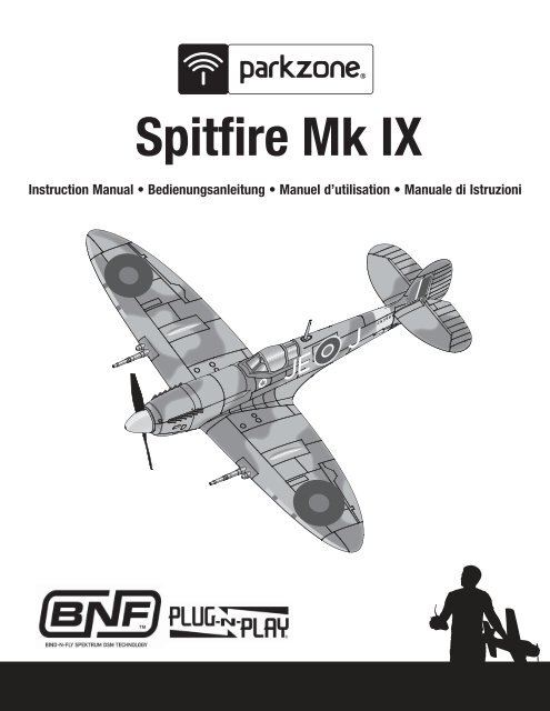
<strong>Spitfire</strong> Mk <strong>IX</strong>Instruction <strong>Manual</strong> • Bedienungsanleitung • Manuel d’utilisation • <strong>Manual</strong>e di Istruzioni
ENNOTICEAll instructions, warranties and other collateral documents are subject to change at the sole discretion of <strong>Horizon</strong> <strong>Hobby</strong>, Inc. For up-to-date productliterature, visit www.horizonhobby.com and click on the support tab for this product.Meaning of Special Language:The following terms are used throughout the product literature to indicate various levels of potential harm when operating this product:NOTICE: Procedures, which if not properly followed, create a possibility of physical property damage AND little or no possibility of injury.CAUTION: Procedures, which if not properly followed, create the probability of physical property damage AND a possibility of serious injury.WARNING: Procedures, which if not properly followed, create the probability of property damage, collateral damage, and serious injury OR create a highprobability of superfi cial injury.WARNING: Read the ENTIRE instruction manual to become familiar with the features of the product before operating. Failure to operate the productcorrectly can result in damage to the product, personal property and cause serious injury.This is a sophisticated hobby product. It must be operated with caution and common sense and requires some basic mechanical ability. Failure to operate thisProduct in a safe and responsible manner could result in injury or damage to the product or other property. This product is not intended for use by childrenwithout direct adult supervision. Do not attempt disassembly, use with incompatible components or augment product in any way without the approval of <strong>Horizon</strong><strong>Hobby</strong>, Inc. This manual contains instructions for safety, operation and maintenance. It is essential to read and follow all the instructions and warnings in themanual, prior to assembly, setup or use, in order to operate correctly and avoid damage or serious injury.Additional Safety Precautions and WarningsAs the user of this product, you are solely responsible for operating in a manner that does not endanger yourself and others or result in damage to the product orthe property of others.This model is controlled by a radio signal subject to interference from many sources outside your control. This interference can cause momentary loss of controlso it is advisable to always keep a safe distance in all directions around your model, as this margin will help avoid collisions or injury.Age Recommendation: Not for children under 14 years. This is not a toy.• Always keep a safe distance in all directions around your model to avoid collisions or injury. This model is controlled by a radio signal subject to interferencefrom many sources outside your control. Interference can cause momentary loss of control• Always operate your model in open spaces away from full-size vehicles, traffi c and people.• Always carefully follow the directions and warnings for this and any optional support equipment (chargers, rechargeable battery packs, etc.).• Always keep all chemicals, small parts and anything electrical out of the reach of children.• Always avoid water exposure to all equipment not specifi cally designed and protected for this purpose. Moisture causes damage to electronics.• Never place any portion of the model in your mouth as it could cause serious injury or even death.• Never operate your model with low transmitter batteries.Battery WarningsThe Battery Charger included with your aircraft is designed to safely charge the Li-Po battery.CAUTION: All instructions and warnings must be followed exactly. Mishandling of Li-Po batteries can result in a fi re, personal injury, and/or property damage.• By handling, charging or using the included Li-Po battery you assume allrisks associated with lithium batteries.• If at any time the battery begins to balloon or swell, discontinue use immediately.If charging or discharging, discontinue and disconnect. Continuingto use, charge or discharge a battery that is ballooning or swelling canresult in fi re.• Always store the battery at room temperature in a dry area for best results.• Always transport or temporarily store the battery in a temperature range of40–120º F. Do not store battery or model in a car or direct sunlight. If storedin a hot car, the battery can be damaged or even catch fi re.• NEVER USE A Ni-Cd OR Ni-MH CHARGER. Failure to charge the battery witha compatible charger may cause fi re resulting in personal injury and/orproperty damage.• Never discharge Li-Po cells to below 3V under load.• Never cover warning labels with hook and loop strips.• Never leave charging batteries unattended.• Never charge batteries outside safe temperature range.• Never charge damaged batteries.2
BIND PLUGENThank you for purchasing the ParkZone ® Spitfi re Mk <strong>IX</strong>. You are just minutes away from one of the most exciting RC warbird experiences available. The SupermarineSpitfi re is an icon of British grit and determination. Its fl uid lines are as much a work of art as the aerodynamics. ParkZone has brilliantly captured its powerand grace with this remarkably scale, brushless Mk <strong>IX</strong> replica. The Mk <strong>IX</strong> was developed by Supermarine in 1942 to counter the threat posed by the Focke Wulf190. It also has the distinction of being the fi rst Allied warplane to shoot down an Me-262 jet.Before you take your fi rst fl ight, however, you must thoroughly read this manual. Along with the assembly instructions, you’ll fi nd important setup tips, a pre-fl ightchecklist and a handy troubleshooting guide. It’s all here so your fi rst fl ight, and everyone after, is as rewarding as it can be.Includes:Table of ContentsBattery Warnings .............................................................................. 2Charging the Flight Battery ............................................................... 4Low Voltage Cutoff (LVC) ................................................................... 4Transmitter and Receiver Binding ...................................................... 5Installing Battery ............................................................................... 5Before Flight ..................................................................................... 6Installing a Receiver .......................................................................... 6Battery Selection and Installation ...................................................... 6Installing Wing .................................................................................. 6Installing <strong>Horizon</strong>tal Tail .................................................................... 7Installing Cannons and Antenna ........................................................ 7Installing Landing Gear ..................................................................... 7Installing Optional Retractable Landing Gear ..................................... 8Installing Clevises on Control Horns and Control Centering ................ 8Factory Settings ................................................................................ 8Center of Gravity (CG) ....................................................................... 8Control Direction Test ........................................................................ 9Dual Rates ...................................................................................... 10Service of Power Components ........................................................ 10Flying Tips and Repairs ................................................................... 11First Flight Preparation .................................................................... 11Maintenance After Flying ................................................................ 11AMA National Model Aircraft Safety Code ........................................ 12Troubleshooting Guide .................................................................... 13Limited Warranty ............................................................................ 14Contact Information ........................................................................ 15Compliance Information for the European Union .............................. 15Parts Contacts ................................................................................ 55Replacement Parts ......................................................................... 55Optional Parts ................................................................................. 5643.2 in (1100mm)Bind-N-Fly ®AircraftPlug-N-Play ®Aircraft37.3 in (950mm)41.1 oz (1170 g)InstalledInstalledInstalledInstalledIncludedNeeded toCompleteInstalledInstalledInstalledNeeded toCompleteNeeded toCompleteNeeded toComplete15 size BL outrunner; 950KvEFL 30A Pro SB brushless ESC(4) ServosRecommended Receiver: Spektrum DSM2 or DSMX ® full range or park fl yer sport receiverBattery: 2200mA 3S 25C Li-PoBattery Charger: 300mA-2.0A2-3 cell Li-Po battery chargerRecommended Transmitter:Full-Range 2.4GHz with Spektrum DSM2 /DSMX ® technology.To register your product online, visit www.parkzone.com3
ENCharging the Flight BatteryYour Spitfi re Mk <strong>IX</strong> comes with a DC balancing charger and 3S Li-Po battery.You should only charge your battery with the included charger. Never leave thebattery and charger unattended during the charge process. Failure to follow theinstructions properly could result in a fi re. When charging, make certain the batteryis on a heat-resistant surface. Charge the fl ight battery while assemblingthe aircraft. Install the fully charged battery to perform control tests and binding.DC Li-Po Balancing Charger Features• Charges 2- to 3-cell lithium polymer battery packs• Variable charge rates from 300mAh to 2-amp• Simple single push-button operation• LED charge status indicator• LED cell balance indicator• Audible beeper indicates power and charge status• 12V accessory outlet input cordSpecifications• Input power: 12V DC, 3-amp• Charges 2- to 3-cell Li-Po packs with minimumcapacity of 300mAh3S 11.1V 2200mAh 25C Li-Po Battery Pack (PKZ1029)The ParkZone® 3S Li-Po battery pack features a balancing lead that allowsyou to safely charge your battery pack when used with the included ParkZoneLi-Po balancing charger.CAUTION: The balance connector must be inserted into the correct portof your charger prior to charging.The Battery Charging Process1. Charge only batteries that are cool to the touch and are not damaged. Look at the battery to make sure it is not damaged e.g., swollen, bent, broken orpunctured.2. Attach the input cord of the charger to the appropriate power supply (12V accessory outlet).3. When the Li-Po charger has been correctly powered up, there will be an approximate 3-second delay, then an audible “beep” and the green (ready)LED will fl ash.4. Turn the control on the Amps selector so the arrow points to the charging rate required for the Battery (the Spitfi re Mk <strong>IX</strong>’s included 2200mAh Li-Pobattery will charge at 2.0 amps). DO NOT change the charge rate once the battery begins charging.5. Move the cell selector switch to 3-cell for your battery.6. Connect the Balancing Lead of the Battery to the 3-cell (it has 4 pins) charger port.7. The green and red LEDs may fl ash during the charging process when the charger is balancing cells. Balancing prolongs the life of the battery.8. When the battery is fully charged, there will be an audible beep for about 3 seconds and the green LED will shine continuously. Attempting to chargean over-discharged battery will cause the charger to repeatedly fl ash and beep, indicating an error has occurred.9. Always unplug the battery from the charger immediately upon completion of charging.CAUTION: Overcharging a battery can cause a fi re.CAUTION: Only use a charger specifi cally designed to charge a Li-Pobattery. Failure to do so could result in fi re causing injury or propertydamage.NOTICE: If using a battery other than the included Li-Po battery, refer to yourbattery manufacturer’s instructions for charging.CAUTION: Never exceed the recommended charge rate.Low Voltage Cutoff (LVC)When a Li-Po battery is discharged below 3V per cell, it will not hold a charge.The ESC protects the fl ight battery from over-discharge using Low VoltageCutoff (LVC). Before the battery charge decreases too much, LVC removespower supplied to the motor. Power to the motor pulses, showing that somebattery power is reserved for fl ight control and safe landing.When the motor pulses, land the aircraft immediately and recharge thefl ight battery.Disconnect and remove the Li-Po battery from the aircraft after use to preventtrickle discharge. Fully charge your Li-Po battery before storing it. Duringstorage make sure battery charge does not go below 3V per cell.4
ENTransmitter and Receiver BindingBinding is the process of programming the receiver of the control unit to recognize the GUID (Globally Unique Identifi er) code of a single specifi c transmitter. Youneed to ‘bind’ your chosen Spektrum DSM2/DSMX technology equipped aircraft transmitter to the receiver for proper operation.Please visit www.bindnfl y.com for a complete list of compatible transmitters.BIND PLUGWhen using a Futaba transmitter with a Spektrum DSM module, you must reverse the throttle channel.Binding Procedure Reference Table1. Read transmitter instructions for binding to a receiver (location of transmitter’s Bind control).2. Make sure the transmitter is powered off.3. Move the transmitter controls to neutral (fl ight controls: rudder, elevators and ailerons) or to lowpositions (throttle, throttle trim).*4. Install a bind plug in the receiver bind port.5. Connect the fl ight battery to the ESC.6. The receiver LED will begin to fl ash rapidly.7. Power on the transmitter while holding the transmitter bind button or switch. Refer to yourtransmitter’s manual for binding button or switch instructions.8. When the receiver binds to the transmitter, the light on the receiver will be solid and the ESC willproduce a series of sounds. The series of sounds is a long tone, then three short tones thatconfi rm the LVC is set for the ESC.9. Remove the bind plug from the bind port.10. Safely store the bind plug (some owners attach the bind plug to their transmitter using two-partloops and clips).11. The receiver should retain the binding instructions received from the transmitter until anotherbinding is done.* The throttle will not arm if the transmitter’s throttle control is not put at the lowest position. If you encounter problems, follow binding instructions and referto transmitter troubleshooting guide for other instructions. If needed, contact the appropriate <strong>Horizon</strong> Product Support offi ce.Installing Battery1. Carefully lift the back of battery hatch (A) and pull hatch pins from the holesin the fuselage to remove hatch.2. Install fl ight battery (B) all the way to the front of the battery compartment.3. Connect battery connector to the ESC power connector.4. Make sure the fl ight battery (B) is held tight using a hook and loop strap (C).5. Install battery hatch on fuselage. Make sure the magnets on hatch andfuselage touch.ACAUTION: Always disconnect the Li-Po battery from the aircraft receiverwhen not fl ying to avoid over-discharging the battery. Batteries discharged toa voltage lower than the lowest approved voltage may be damaged, resultingin loss of performance and potential fi re when batteries are charged.BCAUTION: Always keep hands away from propeller. When armed, themotor will turn the propeller in response to any throttle movement.CPrevent damage to paint on the fuselage and hatch byinstalling a small amount of included clear tape. Usefolded tape as a handle to lift the hatch from the fuselage.5
ENBefore Flight1 2 3• Lower throttle andthrottle trim tolowest settings.Power onTransmitter• Connect batteryto ESC.Wait 5secondsContinuous LEDSeries of tonesInstalling a Receiver1. Remove the wing to install a receiver.2. Install your park fl yer or full range receiver in the fuselage using hook andloop tape or double-sided servo tape.3. Attach the elevator and rudder servo connectors to the appropriate channelsof the receiver.Battery Selection and Installation1. We recommend the ParkZone 2200mAh 11.1V 25C Li-Po battery (PKZ1029).2. If using another battery, the battery must be at least a 25C 2100mAh battery.4. Attach the aileron Y-harness to the aileron channel of the receiver.5. Attach the ESC connector to the throttle channel of the receiver.3. Your battery should be approximately the same capacity, dimensions andweight as the ParkZone Li-Po battery to fi t in the fuselage without changingthe center of gravity.Installing Wing1. Where installed, remove battery hatch fromfuselage.2. Turn aircraft over so the bottom of the fuselagefaces up.3. Put the wing’s guide pins in the fuselageplate holes.4. Where used, put aileron and retractable landinggear connectors in the hole in the fuselage.Make sure connectors do not fall out of thefuselage after wing is installed.5. Align and attach wing to the fuselage usingtwo screws.CAUTION: Do NOT crush or otherwisedamage wiring when attaching wing to fuselage.6. Turn assembled fuselage and wing so thebottom of the wing is down.7. Connect servo connectors to the receiver orY-harnesses. There is no difference between twoconnections on a Y-harness. Left and right servoconnectors do not have to be connected toa particular side of a Y-harness.8. Where needed, disassemble in reverse order.3 X 25mm (2)6NOTICE: Use of CA accelerant on your model can damage paint. DO NOT wipe accelerant from model, but let accelerant evaporate.
ENInstalling <strong>Horizon</strong>tal Tail1. Install the tube in the hole in the fuselage.2. Install the left horizontal tail on tube.3. Install the left horizontal tail in fuselage mount.4. Install the right horizontal tail on tube, in mountand on connector with left tail.5. Apply four pieces of tape on the fuselagemounts and top and bottom of the horizontal tail.6. Attach clevis to the elevator control horn (seeinstructions for clevis connection).7. When needed, disassemble in reverse order.Installing Cannons and Antenna1. Install cannons on the front of the wings usingtwo screws (A) for each cannon.2. Install antenna in slot on top of the fuselagebehind the canopy.A1.5 X 7mm (4)Installing Landing GearIntallation1. Install the left landing gear plate (A) (markedwith an L) in wing using four screws (B).2. Install the left landing gear strut in plate (asshown).3. Install the left cover (C) (marked L) on strut (D)using two screws (E).4. Install wheel on the strut using collar. Make surethe bushing side of the wheel is toward the bendin the strut.5. Tighten setscrew (F) in collar. Use a smallamount of threadlock to hold setscrew in collar.6. Install the left wheel pant (G) (marked L)on the strut.7. Install right landing gear the same as leftlanding gear.RemovalWhen needed, disassemble in reverse order.B3 X 23mm (8)AGDF3 X 4mm (2)CE2 X 12mm (4)7
ENInstalling Optional Retractable Landing Gear1. Remove wing from the model and disconnect aileron servos fromY-harness.2. Remove fi xed landing gear and included parts from the wing.3. Install required struts (A) (PKZ5717, sold separately) on retract gear (B)(EFLG100, sold separately) according to the instructions included withelectric retracts.Pre-bent retract struts with three spring coils are required so the wheelscan go in the wheel wells without being blocked.AD3 X 23mm (8)4. Plug retracts into gear y-harness connectors in the landing gear mount.5. Install retracts in wing using left and right retract cover plates (C)(marked L and R) and eight screws (D).6. Pull extra gear y-harness slack through the hole in the middle of thewing on the top.7. Place each gear y-harness connector in the slot on the inside edge ofeach radiator scoop (E).8. In the fuselage, connect the aileron servos to aileron Y-harness andconnect gear Y-harness to GEAR port on receiver.9. Install wheels, collars and wheel pants on the retract struts as inlandinggear installation instructions.10. Install wing on model.BCEInstalling Clevises on Control Horns and Control CenteringTip: Turn the clevis clockwise or counterclockwise on the linkage.• Pull the tube from the clevis to the linkage.• Carefully spread the clevis and put the clevis pin in a selected hole inthe control horn.• Move the tube to hold the clevis on the control horn.1. 4.2.5.After binding a transmitter to the model receiver, set trims and sub-trims to0, then adjust clevises to center the control surfaces.3.6.Factory SettingsFly the model at factory settings before making changes. For pilots whowish for more control throw, adjust position of linkages on servo arms andcontrol horns for increased travel.ArmsElevatorAileronsRudderHornsCenter of Gravity (CG)Place battery all the way forward in the fuselageand hold the battery in place using a hook and loopstrap. It is easiest to balance the Spitfi re Mk <strong>IX</strong> withthe aircraft inverted.65mm(2.55 inches) from leadingedge of the wing at fuselage8
ENControl Direction TestBind your aircraft and transmitter before doing these tests. Move the controls on the transmitter to make sure the aircraft control surfaces move correctly.After doing the Control Test, correctly set failsafe. Make sure transmitter controls are at neutral and the throttle and throttle trim are in the low position thenrebind the model to your transmitter. If the receiver loses link to the transmitter, failsafe makes the controls and throttle go to these settings made at binding.ElevatorUp ElevatorDown ElevatorAileronStickLeftStickRightRudderStickLeftStickRight9
ENDual RatesWe recommend using a DSM2/DSMX aircraft transmitter capable of dual rates.Adjust according to individual preferences after initial fl ight.High RateLow RateAileron 15mm up/down 11mm up/downElevator 14mm up/down 10mm up/downRudder 25mm left/right 18mm left/rightService of Power ComponentsDisassembly1. Remove screw (A) and nose cone (B) from spinner nut (C).2. Use a tool to remove the spinner nut.3. Remove propeller (D), nose cone plate (E), backplate (F) and collet (G) frommotor shaft.4. Remove six screws (H) from cowling (I).5. Carefully remove cowling from fuselage. Paint may keep cowling attachedto the fuselage.6. Remove four screws (J) from the motor mount (K) and fuselage.7. Disconnect motor wires from ESC wires.8. Remove four screws (L) and motor (M) from motor mount.Keep rubber washers attached to the motor mount when removing screwsand motor from motor mount.AssemblyAssemble in reverse order.NOTICE: Make sure the propeller side with the numbers for diameter andpitch (for example, 9.5 x 7.5) faces out from the backplate. A tool is requiredto tighten the spinner nut on the collet.BD EI F G<strong>MK</strong>L3X10mm (4)JAH2X10mm (4)3X10mmC1.5X5mm (6)Not all wiring shown.CAUTION: Always disconnect the fl ight battery from the model before removing the propeller.10
ENFlying Tips and RepairsRange Check your Radio SystemAfter fi nal assembly, range check the radio system with the Spitfi re Mk <strong>IX</strong>.Refer to your specifi c transmitter instruction manual for range test information.FlyingAlways choose a wide-open space for fl ying your ParkZone Spitfi re Mk <strong>IX</strong>.It is ideal that you fl y at a sanctioned fl ying fi eld. If you are not fl ying at anapproved site, always avoid fl ying near houses, trees, wires and buildings. Youshould also be careful to avoid fl ying in areas where there are many people,such as busy parks, schoolyards or soccer fi elds. Consult local laws andordinances before choosing a location to fl y your aircraft.The Spitfi re Mk <strong>IX</strong> is meant to be fl own like a warbird. Care must be givenwhen providing elevator input, especially when fl ying at higher speeds.If excessive elevator is given, especially at higher speeds, you could cause thewing to fl ex when making tight turns.Fly in this area(upwind of pilot)600 feet (182.8 m)Stand hereLandingFor your fi rst fl ights, set your transmitter timer or a stopwatch to 7 minutes.Adjust your timer for longer or shorter fl ights once you have fl own the model.When the motor pulses, land the aircraft immediately and recharge thefl ight battery. It is not recommended to fl y the battery to LVC.The Spitfi re Mk <strong>IX</strong> is easiest to land doing a wheellanding (two point). A wheel landing (two point) iswhen the airplane touches down on the main landinggear fi rst with the tailwheel off the ground. The Spitfi reMk <strong>IX</strong> can be landed in three-point attitude, whereall three wheels touch down at the same time, butthe wheel landing is easier to accomplish. Once theairplane touches down, reduce back pressure on theelevator stick to prevent the plane from becomingairborne again. Fly the airplane down to the groundusing 1/4 –1/3 throttle to allow for enough energy fora proper fl are.Alwaysdecrease throttle atpropeller strike.Avoid sharp turns on the ground until the plane has slowed enough to preventscraping the wingtips.NOTICE: When fi nished fl ying, never keep the airplane in the sun. Do not storethe aircraft in a hot, enclosed area such as a car. Doing so can damagethe foam.RepairsThanks to the Z-Foam construction of the Spitfi re Mk <strong>IX</strong>, repairs to the foamcan be made using virtually any adhesive (hot glue, regular CA (cyanocrylateadhesive), epoxy, etc). When parts are not repairable, see the ReplacementParts List for ordering by item number.NOTICE: Use of CA accelerant on your model can damage paint. DO NOThandle model until accelerant fully dries.First Flight Preparation1. Remove and inspect contents.2. Charge fl ight battery.3. Read this instruction manual thoroughly.4. Fully assemble model.5. Install the fl ight battery in the aircraft (once it has been fully charged).6. Bind aircraft to your transmitter.7. Make sure linkages move freely.8. Perform the Control Direction Test with the transmitter.9. Adjust fl ight controls and transmitter.10. Perform a radio system Range Check.11. Find a safe and open area.12. Plan fl ight for fl ying fi eld conditions.Maintenance After Flying1. Disconnect fl ight battery from ESC (Required for Safety and battery life).2. Power off transmitter.3. Remove fl ight battery from aircraft.4. Recharge fl ight battery.5. Repair or replace all damaged parts.6. Store fl ight battery apart from aircraft and monitor the battery charge.7. Make note of fl ight conditions and fl ight plan results,planning for future fl ights.11
ENAMA National Model Aircraft Safety CodeEffective January 1, 2011A. GENERALA model aircraft is a non-human-carrying aircraft capable of sustained fl ightin the atmosphere. It may not exceed limitations of this code and is intendedexclusively for sport, recreation and/or competition. All model fl ights mustbe conducted in accordance with this safety code and any additional rulesspecifi c to the fl ying site.1. Model aircraft will not be fl own:(a) In a careless or reckless manner.(b) At a location where model aircraft activities are prohibited.2. Model aircraft pilots will:(a) Yield the right of way to all man carrying aircraft.(b) See and avoid all aircraft and a spotter must be used when appropriate.(AMA Document #540-D-See and Avoid Guidance.)(c) Not fl y higher than approximately 400 feet above ground level withinthree (3) miles of an airport, without notifying the airport operator.(d) Not interfere with operations and traffi c patterns at any airport, heliportor seaplane base except where there is a mixed use agreement.(e) Not exceed a takeoff weight, including fuel, of 55 pounds unless incompliance with the AMA Large Model Aircraft program. (AMADocument 520-A)(f) Ensure the aircraft is identifi ed with the name and address or AMAnumber of the owner on the inside or affi xed to the outside of the modelaircraft. (This does not apply to model aircraft fl own indoors).(g) Not operate aircraft with metal-blade propellers or with gaseous boostsexcept for helicopters operated under the provisions of AMA Document#555.(h) Not operate model aircraft while under the infl uence of alcohol or whileusing any drug which could adversely affect the pilot’s ability to safelycontrol the model.(i) Not operate model aircraft carrying pyrotechnic devices which explodeor burn, or any device which propels a projectile or drops any objectthat creates a hazard to persons or property.Exceptions:• Free Flight fuses or devices that burn producing smoke and aresecurely attached to the model aircraft during fl ight.• Rocket motors (using solid propellant) up to a G-series size maybe used provided they remain attached to the model during fl ight.Model rockets may be fl own in accordance with the NationalModel Rocketry Safety Code but may not be launched frommodel aircraft.• Offi cially designated AMA Air Show Teams (AST) are authorized touse devices and practices as defi ned within the Team AMAProgram Document (AMA Document #718).(j) Not operate a turbine-powered aircraft, unless in compliance with theAMA turbine regulations. (AMA Document #510-A).3. Model aircraft will not be fl own in AMA sanctioned events, air shows ormodel demonstrations unless:(a) The aircraft, control system and pilot skills have successfullydemonstrated all maneuvers intended or anticipated prior to thespecifi c event.(b) An inexperienced pilot is assisted by an experienced pilot.4. When and where required by rule, helmets must be properly worn andfastened. They must be OSHA, DOT, ANSI, SNELL or NOCSAE approved orcomply with comparable standards.B. RADIO CONTROL1. All pilots shall avoid fl ying directly over unprotected people, vessels,vehicles or structures and shall avoid endangerment of life and propertyof others.2. A successful radio equipment ground-range check in accordance withmanufacturer’s recommendations will be completed before the fi rst fl ightof a new or repaired model aircraft.3. At all fl ying sites a safety line(s) must be established in front of which allfl ying takes place (AMA Document #706-Recommended Field Layout):(a) Only personnel associated with fl ying the model aircraft are allowed ator in front of the safety line.(b) At air shows or demonstrations, a straight safety line must beestablished.(c) An area away from the safety line must be maintained for spectators.(d) Intentional fl ying behind the safety line is prohibited.4. RC model aircraft must use the radio-control frequencies currently allowedby the Federal Communications Commission (FCC). Only individualsproperly licensed by the FCC are authorized to operate equipment onAmateur Band frequencies.5. RC model aircraft will not operate within three (3) miles of any pre-existingfl ying site without a frequency-management agreement (AMA Documents#922-Testing for RF Interference; #923- Frequency ManagementAgreement)6. With the exception of events fl own under offi cial AMA CompetitionRegulations, excluding takeoff and landing, no powered model may befl own outdoors closer than 25 feet to any individual, except for the pilotand the pilot’s helper(s) located at the fl ight line.7. Under no circumstances may a pilot or other person touch a model aircraftin fl ight while it is still under power, except to divert it from striking anindividual. This does not apply to model aircraft fl own indoors.8. RC night fl ying requires a lighting system providing the pilot with a clearview of the model’s attitude and orientation at all times.9. The pilot of a RC model aircraft shall:(a) Maintain control during the entire fl ight, maintaining visual contactwithout enhancement other than by corrective lenses prescribed forthe pilot.(b) Fly using the assistance of a camera or First-Person View (FPV) onlyin accordance with the procedures outlined in AMA Document #550.Please see your local or regional modeling association’s guidelines for proper, safeoperation of your model aircraft.12
ENTroubleshooting GuideProblem Possible Cause SolutionAircraft will not respondto throttle but responds toother controlsExtra propeller noise orextra vibrationReduced fl ight time or aircraftunderpoweredAircraft will not Bind (duringbinding) to transmitterAircraft will not link (afterbinding) to transmitterControl surface does notmoveThrottle is not at idle and/or throttle trim is too highThrottle servo travel is lower than 100%Throttle channel is reversedDamaged propeller and spinner, collet or motorPropeller is out of balanceFlight battery charge is lowPropeller is installed backwardsFlight battery is damagedFlight conditions may be too coldTransmitter is too near aircraft during binding processAircraft or transmitter is too close to large metal objectBind plug is not installed correctly in bind portFlight battery/Transmitter battery charge is too lowTransmitter is too near aircraft during linking processAircraft or transmitter is too close to large metal objectBind plug is left installed in bind portAircraft bound to different model memory (ModelMatch radiosonly)Flight battery/Transmitter battery charge is too lowTransmitter may have been bound using different DSM ProtocolControl surface, control horn, linkage or servo damageWire is damaged or connections are looseReset controls with throttle stick and throttle trimat lowest settingMake sure throttle servo travel is 100% or greaterReverse throttle channel on transmitterReplace damaged partsBalance or replace propellerCompletely recharge fl ight batteryInstall propeller with numbers facing forwardReplace fl ight battery and follow fl ight battery instructionsMake sure battery is warm before useMove powered transmitter a few feet from aircraft,disconnect and reconnect fl ight battery to aircraftMove aircraft or transmitter away from large metal objectInstall bind plug in bind port and bind aircraft to transmitterReplace/recharge batteriesMove powered transmitter a few feet from aircraft,disconnect and reconnect fl ight battery to aircraftMove aircraft or transmitter away from large metal objectRebind transmitter to aircraft and remove bind plug beforecycling powerSelect correct model memory on transmitterReplace/recharge batteriesBind aircraft to transmitterReplace or repair damaged parts and adjust controlsDo a check of wires and connections, connector replace as neededTransmitter is not bound correctly or the incorrect modelRe-bind or select correct model in transmitterwas selectedBEC (Battery Elimination Circuit) of the ESC is damagedReplace ESCControls reversed Transmitter settings are reversed Do the Control Direction Test and adjust controls ontransmitter appropriatelyMotor power pulses thenmotor loses powerESC uses default soft Low Voltage Cutoff (LVC)Weather conditions might be too coldBattery is old, worn out, or damagedBattery C rating might be too smallRecharge fl ight battery or replace batterythat is no longer performingPostpone flight until weather is warmerReplace batteryUse recommended 25C battery13
ENLimited WarrantyWhat this Warranty Covers<strong>Horizon</strong> <strong>Hobby</strong>, Inc. (“<strong>Horizon</strong>”) warrants to the original purchaser that theproduct purchased (the “Product”) will be free from defects in materials andworkmanship at the date of purchase.What is Not CoveredThis warranty is not transferable and does not cover (i) cosmetic damage, (ii)damage due to acts of God, accident, misuse, abuse, negligence, commercialuse, or due to improper use, installation, operation or maintenance, (iii) modification of or to any part of the Product, (iv) attempted service by anyone otherthan a <strong>Horizon</strong> <strong>Hobby</strong> authorized service center, or (v) Products not purchasedfrom an authorized <strong>Horizon</strong> dealer.OTHER THAN THE EXPRESS WARRANTY ABOVE, HORIZON MAKES NO OTHERWARRANTY OR REPRESENTATION, AND HEREBY DISCLAIMS ANY AND ALLIMPLIED WARRANTIES, INCLUDING, WITHOUT LIMITATION, THE IMPLIED WAR-RANTIES OF NON-INFRINGEMENT, MERCHANTABILITY AND FITNESS FOR APARTICULAR PURPOSE. THE PURCHASER ACKNOWLEDGES THAT THEY ALONEHAVE DETERMINED THAT THE PRODUCT WILL SUITABLY MEET THE REQUIRE-MENTS OF THE PURCHASER’S INTENDED USE.Purchaser’s Remedy<strong>Horizon</strong>’s sole obligation and purchaser’s sole and exclusive remedy shall bethat <strong>Horizon</strong> will, at its option, either (i) service, or (ii) replace, any Productdetermined by <strong>Horizon</strong> to be defective. <strong>Horizon</strong> reserves the right to inspectany and all Product(s) involved in a warranty claim. Service or replacementdecisions are at the sole discretion of <strong>Horizon</strong>. Proof of purchase is required forall warranty claims. SERVICE OR REPLACEMENT AS PROVIDED UNDER THISWARRANTY IS THE PURCHASER’S SOLE AND EXCLUSIVE REMEDY.Limitation of LiabilityHORIZON SHALL NOT BE LIABLE FOR SPECIAL, INDIRECT, INCIDENTAL ORCONSEQUENTIAL DAMAGES, LOSS OF PROFITS OR PRODUCTION OR COMMER-CIAL LOSS IN ANY WAY, REGARDLESS OF WHETHER SUCH CLAIM IS BASED INCONTRACT, WARRANTY, TORT, NEGLIGENCE, STRICT LIABILITY OR ANY OTHERTHEORY OF LIABILITY, EVEN IF HORIZON HAS BEEN ADVISED OF THE POSSIBIL-ITY OF SUCH DAMAGES. Further, in no event shall the liability of <strong>Horizon</strong> exceedthe individual price of the Product on which liability is asserted. As <strong>Horizon</strong> hasno control over use, setup, fi nal assembly, modifi cation or misuse, no liabilityshall be assumed nor accepted for any resulting damage or injury. By the actof use, setup or assembly, the user accepts all resulting liability. If you as thepurchaser or user are not prepared to accept the liability associated with theuse of the Product, purchaser is advised to return the Product immediately innew and unused condition to the place of purchase.Inspection or ServicesIf this Product needs to be inspected or serviced, please use the <strong>Horizon</strong> OnlineService Request submission process found on our website or call <strong>Horizon</strong> toobtain a Return Merchandise Authorization (RMA) number. Pack the Productsecurely using a shipping carton. Please note that original boxes may beincluded, but are not designed to withstand the rigors of shipping without additionalprotection. Ship via a carrier that provides tracking and insurance forlost or damaged parcels, as <strong>Horizon</strong> is not responsible for merchandise until itarrives and is accepted at our facility. An Online Service Request is availableat www.horizonhobby.com under the Support tab. If you do not have internetaccess, please contact <strong>Horizon</strong> Product Support to obtain a RMA numberalong with instructions for submitting your product for service. When calling<strong>Horizon</strong>, you will be asked to provide your complete name, street address,email address and phone number where you can be reached during businesshours. When sending product into <strong>Horizon</strong>, please include your RMA number, alist of the included items, and a brief summary of the problem. A copy of youroriginal sales receipt must be included for warranty consideration. Be sureyour name, address, and RMA number are clearly written on the outside of theshipping carton.Notice: Do not ship LiPo batteries to <strong>Horizon</strong>. If you have any issue with aLiPo battery, please contact the appropriate <strong>Horizon</strong> ProductSupport office.Warranty RequirementsFor Warranty consideration, you must include your original sales receiptverifying the proof-of-purchase date. Provided warranty conditions havebeen met, your Product will be serviced or replaced free of charge. Service orreplacement decisions are at the sole discretion of <strong>Horizon</strong>.Non-Warranty ServiceShould your service not be covered by warranty service will be completedand payment will be required without notification or estimate ofthe expense unless the expense exceeds 50% of the retail purchase cost.By submitting the item for service you are agreeing to payment of the servicewithout notifi cation. Service estimates are available upon request. You mustinclude this request with your item submitted for service. Non-warranty serviceestimates will be billed a minimum of ½ hour of labor. In addition you will bebilled for return freight. <strong>Horizon</strong> accepts money orders and cashiers checks, aswell as Visa, MasterCard, American Express, and Discover cards. By submittingany item to <strong>Horizon</strong> for service, you are agreeing to <strong>Horizon</strong>’s Terms and Conditionsfound on our website www.horizonhobby.com/Service/Request/.LawThese terms are governed by Illinois law (without regard to confl ict of lawprincipals). This warranty gives you specifi c legal rights, and you may alsohave other rights which vary from state to state. <strong>Horizon</strong> reserves the right tochange or modify this warranty at any time without notice.Warranty ServicesQuestions, Assistance, and ServicesYour local hobby store and/or place of purchase cannot provide warranty supportor service. Once assembly, setup or use of the Product has been started,you must contact your local distributor or <strong>Horizon</strong> directly. This will enable<strong>Horizon</strong> to better answer your questions and service you in the event that youmay need any assistance. For questions or assistance, please direct your emailto productsupport@horizonhobby.com, or call 877.504.0233 toll free to speakto a Product Support representative. You may also find information on ourwebsite at www.horizonhobby.com14
ENContact InformationCountry of Purchase <strong>Horizon</strong> <strong>Hobby</strong> Address Phone Number/Email AddressUnited States ofAmericaUnited KingdomGermanyFrance<strong>Horizon</strong> Service Center(Electronics and engines)<strong>Horizon</strong> Product Support(All other products)<strong>Horizon</strong> <strong>Hobby</strong> Limited<strong>Horizon</strong> Technischer Service<strong>Horizon</strong> <strong>Hobby</strong> SAS4105 Fieldstone RdChampaign, Illinois61822 USA4105 Fieldstone RdChampaign, Illinois61822 USAUnits 1-4 Ployters RdStaple TyeHarlow, EssexCM18 7NSUnited KingdomHamburger Str. 1025335 ElmshornGermany14 Rue Gustave EiffelZone d’Activité du Réveil Matin91230 Montgeron877-504-0233Online Repair Request:visit www.horizonhobby.com/service877-504-0233productsupport@horizonhobby.com+44 (0) 1279 641 097sales@horizonhobby.co.uk+49 4121 46199 66service@horizonhobby.de+33 (0) 1 60 47 44 70infofrance@horizonhobby.comCompliance Information for the European UnionDeclaration of Conformity(in accordance with ISO/IEC 17050-1)No. HH2011071503Product(s):Spitfi re Mk <strong>IX</strong> BNFItem Number(s):PKZ5780Equipment class: 1The object of declaration described above is in conformity with the requirementsof the specifi cations listed below, following the provisions of theEuropean R&TTE directive 1999/5/EC and EMC Directive 2004/108/EC:EN 301 489-1 V1.7.1: 2006EN 301 489-17 V1.3.2: 2008Declaration of Conformity(in accordance with ISO/IEC 17050-1)No. HH2011071502Product(s):Spitfi re Mk <strong>IX</strong> PNPItem Number(s):PKZ5775Equipment class: 1The object of declaration described above is in conformity with the requirementsof the specifi cations listed below, following the provisions of theEuropean R&TTE directive 1999/5/EC:EN 301 489-1 V1.7.1: 2006EN 301 489-3 V1.4.1: 2008EN55022: 2006,EN55024: 1998+A1: 2001+A2: 2003Signed for and on behalf of:<strong>Horizon</strong> <strong>Hobby</strong>, Inc.Champaign, IL USAJuly 15, 2011Steven A. HallVice PresidentInternational Operations andRisk Management<strong>Horizon</strong> <strong>Hobby</strong>, Inc.Signed for and on behalf of:<strong>Horizon</strong> <strong>Hobby</strong>, Inc.Champaign, IL USAJuly 15, 2011Steven A. HallVice PresidentInternational Operations andRisk Management<strong>Horizon</strong> <strong>Hobby</strong>, Inc.Instructions for disposal of WEEE by users in the European UnionThis product must not be disposed of with other waste. Instead, it is the user’s responsibility to dispose of their waste equipment by handing it overto a designated collections point for the recycling of waste electrical and electronic equipment. The separate collection and recycling of your wasteequipment at the time of disposal will help to conserve natural resources and ensure that it is recycled in a manner that protects human health andthe environment. For more information about where you can drop off your waste equipment for recycling, please contact your local city offi ce, yourhousehold waste disposal service or where you purchased the product.15
DEHINWEISAlle Anweisungen, Garantien und anderen zugehörigen Dokumente können im eigenen Ermessen von <strong>Horizon</strong> <strong>Hobby</strong>, Inc. jederzeit geändert werden. Dieaktuelle Produktliteratur fi nden Sie auf www.horizonhobby.com unter der Registerkarte „Support“ für das betreff ende Produkt.Spezielle Bedeutungen:Die folgenden Begriff e werden in der gesamten Produktliteratur verwendet, um auf unterschiedlich hohe Gefahrenrisiken beim Betrieb dieses Produktshinzuweisen:HINWEIS: Wenn diese Verfahren nicht korrekt befolgt werden, können sich möglicherweise Sachschäden UND geringe oder keine Gefahr vonVerletzungen ergeben.ACHTUNG: Wenn diese Verfahren nicht korrekt befolgt werden, ergeben sich wahrscheinlich Sachschäden UND die Gefahr von schweren Verletzungen.WARNUNG: Wenn diese Verfahren nicht korrekt befolgt werden, ergeben sich wahrscheinlich Sachschäden, Kollateralschäden und schwere VerletzungenODER mit hoher Wahrscheinlichkeit oberfl ächliche Verletzungen.WARNUNG: Lesen Sie die GESAMTE Bedienungsanleitung, um sich vor dem Betrieb mit den Produktfunktionen vertraut zu machen. Wird das Produktnicht korrekt betrieben, kann dies zu Schäden am Produkt oder persönlichem Eigentum führen oder schwere Verletzungen verursachen.Dies ist ein hochentwickeltes <strong>Hobby</strong>-Produkt. Es muss mit Vorsicht und gesundem Menschenverstand betrieben werden und benötigt gewisse mechanischeGrundfähigkeiten. Wird dieses Produkt nicht auf eine sichere und verantwortungsvolle Weise betrieben, kann dies zu Verletzungen oder Schäden am Produktoder anderen Sachwerten führen. Dieses Produkt eignet sich nicht für die Verwendung durch Kinder ohne direkte Überwachung eines Erwachsenen. VersuchenSie nicht ohne Genehmigung durch <strong>Horizon</strong> <strong>Hobby</strong>, Inc., das Produkt zu zerlegen, es mit inkompatiblen Komponenten zu verwenden oder auf jegliche Weise zuerweitern. Diese Bedienungsanleitung enthält Anweisungen für Sicherheit, Betrieb und Wartung. Es ist unbedingt notwendig, vor Zusammenbau, Einrichtung oderVerwendung alle Anweisungen und Warnhinweise im Handbuch zu lesen und zu befolgen, damit es bestimmungsgemäß betrieben werden kann und Schädenoder schwere Verletzungen vermieden werden.Zusätzliche Sicherheitsvorkehrungen und WarnhinweiseAls Benutzer dieses Produkts sind Sie allein dafür verantwortlich, es so zu betreiben, dass es Sie selbst und andere nicht gefährdet und dass es zu keinerBeschädigung des Produkts oder des Eigentums Dritter kommt.Dieses Modell wird von einem Funksignal gesteuert, das Interferenzen von vielen Quellen außerhalb Ihres Einfl ussbereiches unterliegt. Diese Interferenzenkönnen einen augenblicklichen Steuerungsverlust verursachen. Es ist daher ratsam, rund um Ihr Modell in allen Richtungen einen Sicherheitsabstand einzuhalten,da dieser Freiraum Zusammenstöße oder Verletzungen zu vermeiden hilft.Nicht geeignet für Kinder unter 14 Jahren. Dies ist kein Spielzeug.• Halten Sie stets in allen Richtungen einen Sicherheitsabstand um Ihr Modell, um Zusammenstöße oder Verletzungen zu vermeiden.• Betreiben Sie Ihr Modell immer auf einer Freifl äche ohne Fahrzeuge, Verkehr oder Menschen.• Befolgen Sie stets sorgfältig die Anweisungen und Warnhinweise für das Modell und jegliches optionales Zubehör/Hilfsgeräte (Ladegeräte, Akkupacks usw.)• Bewahren Sie alle Chemikalien, Klein und Elektroteile stets außerhalb der Reichweite von Kindern auf.• Setzen Sie Geräte, die für diesen Zweck nicht speziell ausgelegt und geschützt sind, niemals Wasser aus. Feuchtigkeit kann die Elektronik beschädigen.• Stecken Sie keinen Teil des Modells in den Mund, da dies zu schweren Verletzungen oder sogar zum Tod führen kann.• Betreiben Sie Ihr Modell nie mit fast leeren Senderakkus.Akku WarnungenDas mit Ihrem Flugzeug mitgelieferte Akkuladegerät ist für eine sichere Aufl adung der Li-Po-Akkus ausgelegt.ACHTUNG: Alle Anweisungen und Warnhinweise müssen genau befolgt werden. Falsche Handhabung von Li-Po-Akkus kann zu Feuer, Personen- und/oderSachwertschäden führen.• Durch Handhabung, Aufl adung oder Verwendung des mitgeliefertenLi-Po-Akkus übernehmen Sie alle mit Lithiumakkus verbundenen Risiken.• Sollte der Akku zu einem beliebigen Zeitpunkt beginnen, sich aufzublähenoder anzuschwellen, stoppen Sie die Verwendung unverzüglich. Falls diesebeim Laden oder Entladen auftritt, stoppen Sie den Lade-/Entladevorgangunverzüglich, und stecken ihn sofort ab. Wird ein Akku, der sich aufblähtoder anschwillt, weiter verwendet, geladen oder entladen, bestehtBrandgefahr.• Lagern Sie den Akku stets bei Zimmertemperatur an einem trockenen Ort.• Bei Transport oder vorübergehender Lagerung des Akkus muss der Temperaturbereichzwischen ca. 4,4°C bis 48,9°C liegen. Akku oder Modell dürfennicht im Auto oder unter direkter Sonneneinstrahlung gelagert werden. BeiLagerung in einem heißen Auto kann der Akku beschädigt werden odersogar Feuer fangen.• ES DARF KEINESFALLS EIN Ni-Cd- ODER Ni-MH-LADEGERÄT VERWENDETWERDEN. Bei Aufl adung des Akkus mit einem inkompatiblen Ladegerät kannein Brand ausgelöst werden, der zu Personen- und/oder Sachwertschädenführen kann.• Li-Po-Akkus dürfen unter Last niemals unter 3 V entladen werden.• Warnhinweise dürfen niemals mit Klettverschlüssen abgedeckt werden.• Lassen Sie niemals Akkus bei dem Laden unbeaufsichtigt.• Laden Sie niemals Akkus außerhalb ihres sichereren Temperaturbereiches.• Laden Sie niemals beschädigt Akkus.16
BIND PLUGDEVielen Dank für den Kauf der ParkZone® Spitfi re Mk <strong>IX</strong>. Ihre Spitfi re ist in kürzester Zeit fl ugfertig. Die Supermarine Spitfi re ist eine Ikone englischer Entschlossenheit.Ihre fl ießenden Linien verbinden Kunst mit Aerodynamik. ParkZone hat mit dieser bemerkenswerten Mk <strong>IX</strong> Replika die Kraft und Anmut dieses Flugzeugesperfekt eingefangen. Die Mk <strong>IX</strong> wurde 1942 von Supermarine als Gegner der Focke Wulf 190 entwickelt. Einer Spitfi re dieses Typs gelang es als erstenalliierten Flugzeug einen ME 262 Jet im Luftkampf zu besiegen.Bevor Sie zum Erstfl ug starten, müssen Sie bitte diese Bedienungsanleitung sorgfältig lesen. Sie fi nden dort die Anweisungen zur Montage, Einstellungen, eineCheckliste und eine praktische Hilfestellung zur Problemlösung. Damit ihr erster Flug und jeder weitere danach, zu einem ihrer schönsten Flüge werden.inklusiveInhaltsverzeichnisAkku Warnungen ............................................................................ 16Laden des Flugakkus ...................................................................... 18Niederspannungsabschaltung (LVC) ................................................ 18Binden von Sender und Empfänger ................................................. 19Einsetzen des Akkus ....................................................................... 19Vor dem Flug: ................................................................................. 20Einbau des Empfängers .................................................................. 20Akku Auswahl und Einbau ............................................................... 20Montage der Tragfl äche ................................................................. 20Montage des Höhenruders .............................................................. 21Montage der MGs und Antennen ..................................................... 21Montage des Fahrwerkes ................................................................ 21Montage des optionalen elektrischen Einziehfahrwerkes. ................ 22Montage der Gabelköpfe auf dem Ruderhorn und zentrierender Kontrollen ................................................................................. 22Werkseinstellungen ........................................................................ 22Der Schwerpunkt (CG) ................................................................... 22Test der Kontrollen .......................................................................... 23Dual Rate ........................................................................................ 24Wartung der Antriebskomponenten ................................................. 24Tips zum Fliegen und Reparieren .................................................... 25Vorbereitung für den Erstfl ug .......................................................... 25Wartung nach dem Flug .................................................................. 25Hilfestellung zur Fehlersuche und Behebung ................................... 26Garantie und Service Informationen ................................................ 27Kontaktinformationen ...................................................................... 28Konformitätshinweise für die Europäische Union ............................. 28Ersatzteile ....................................................................................... 55Kontaktinformationen für Ersatzteile ............................................... 55Optionale Bauteile ........................................................................... 5643.2 in (1100mm)Bind-N-Fly ®FlugzeugPlug-N-Play ®Flugzeug37.3 in (950mm)41.1 oz (1170 g)InstalliertInstalliertInstalliertInstalliertInklusiveWird nochbenötigtInstalliertInstalliertInstalliertWird nochbenötigtWird nochbenötigtWird nochbenötigt15 BL Außenläufer; 950KvEFL 30A Pro SB Brushless Regler(4) ServosEmpfohlener Empfänger : SpektrumDSM2oder DSMX ® Empfänger mit voller Reichweiteoder Park Flyer Sport EmpfängerAkku: 2200mA 3S 25C Li-PoLadegerät:300mA-2.0A 2-3 S l Li-Po AkkuLadegerätEmpfohlener Sender:2.4GHz mit Spektrum DSM2/DSMX ®Technologie und voller Reichweite.Registrieren Sie ihr Produkt online unter www.parkzone.com17
DELaden des FlugakkusIhre Spitfi re wird mit einem DC Balancer Ladegerät und einem 3S LiPoFlugakku geliefert. Sie müssen den im Lieferumfang enthaltenen LiPoFlugakku mit einem LiPo geeigneten Ladegerät laden. (wie das im Lieferumfangenthaltene Ladegerät)Lassen Sie bei dem Laden den Akku und das Ladegerät niemals unbeaufsichtigt.Ein nicht befolgen dieser Anweisung kann Feuer zur Folge haben.Laden Sie den Akku auf einer hitzebeständigen Oberfl äche. Wir empfehlen denAkku während der Montage des Flugzeuges zu laden. Das aufgeladene Akkuwird zur Funktionsüberprüfung benötigt.Eigenschaften DC LiPo Balancer Ladegerät• Lädt 2 bis 3 S LiPo Akkus• Einstellbarer Ladestrom von 300mAh bis 2A• Einfache Ein-Knopf-Bedienung• LED Lade Status Indikator• LED Balance Indikator• Pieper zeigt Power und Ladestatus an• 12 Volt StromanschlussSpezifikationen• Eingangsspannung: 12V DC, 3 Ampere• Lädt 2 bis 3 S LiPo Akkus mit einer Mindestkapazitätvon 300mAh3S 11.1V 2200mAh LiPo Akku Pack (PKZ1029)Das ParkZone 3S LiPo Akku Pack ist zum sicheren Laden mit dem im Lieferumfangenthaltenen Ladegerät mit einem Balanceranschluß ausgestattet.ACHTUNG: Der Balancer Anschluß des Akkus muß vor dem Laden inden richtigen Anschluß am Ladegerät gesteckt werden.Das Laden des Akkus1. Laden Sie nur Akkus die abgekühlt sind und die Sie mit der Hand anfassen können. Laden Sie nur unbeschädigte Akkus. Vergewissern Sie sich vordem Laden, dass der Akku unbeschädigt, nicht angeschwollen oder nicht durch Druckstellen oder Brüche beschädigt ist.2. Verbinden Sie den 12 Volt Spannungseingang mit einer passenden Stromquelle.3. Haben Sie das Ladegerät korrekt angeschlossen, hören Sie nach ca. drei Sekunden einen Piepton und die grüne LED (Bereit) blinkt.4. Drehen Sie den Regler des Ladestrom so, dass der Pfeil auf dem Regler auf den benötigten Ladestrom zeigt (Der benötigte Ladestrom des 2200mAhAkkus der Spitfi re beträgt 2,0 A.) Sie dürfen den Ladestrom nach dem Ladestart NICHT ändern.5. Wählen Sie mit dem Zellen Schalter die 3 S Zellenzahl ihres Akkus.6. Verbinden Sie den Balanceraschluß des Akkus mit dem Ladegerät. Der Anschluß des 3S Akkus hat 4 Pins.7. Die grüne und rote LED können während des Ladens blinken. Dieses zeigt den Balancervorgang an. Dieser Vorgang trägt zur Lebenserhaltung desAkkus mit bei.8. Ist der Akku vollständig geladen, hören Sie einen 3 Sekunden Piepton und die grüne LED leuchtet. Versuchen Sie einen tief entladenen Akku zu laden,wird das Ladegerät wiederholt blinken und piepen und damit einen Fehler anzeigen.9. Trennen Sie nach dem Laden unverzüglich den Akku vom Ladegerät.ACHTUNG: Ein Überladen des Akkus kann Feuer zur Folge haben.ACHTUNG: Benutzen Sie ausschließlich ein Ladegerät, dass zum Ladenvon LiPo Akkus geeignet ist. Die falsche oder Nichtbenutzung einesgeeigneten Ladegerätes kann ernsthafte Beschädigungen oder Feuerzur Folge habenHINWEIS: Bei Verwendung einer anderen Batterie als das mitgelieferte Li-PoAkku, sollten Sie den Akku den Anweisungen des Herstellers zum Ladenbeziehen.manufacturer’s instructions for charging.ACHTUNG: Überschreiten Sie niemals den empfohlenen Ladestrom.Niederspannungsabschaltung (LVC)Wird ein LiPo Akku unter 3 Volt pro Zelle entladen kann es keine Spannungmehr halten. Der Regler schützt den Akku vor einer Unterspannung mit derNiederspannungsabschaltung (LVC). Unabhängig von der Gasknüppelstellungwird dann die Leistung reduziert, um einen Absinken der Zellenspannung unter3 Volt zu verhindern der Motor fängt dann an zu pulsieren und zeigt damitan, dass noch Energie für eine sichere Landung bleibt. Bitte landen Sie sofortwenn der Motor zu pulsieren anfängt und laden den Akku wieder auf.Trennen Sie den Akku vom Regler und nehmen ihn aus den Flugzeug herausum eine Tiefentladung zu vermeiden. Laden Sie den Akku vor dem Lagern auf.Achten Sie bei dem Lagern darauf, dass die Spannung nicht unter 3V proZelle fällt.18
DEBinden von Sender und EmpfängerDer Bindevorgang verbindet den Sender mit dem Empfänger durch die Übermittlung eines GUID (Globally Unique Identifi er) Signalcodes. Sie müssen für denBetrieb Ihren gewählten Spektrum DSM2/DSMX ® Sender oder Modul an den Empfänger binden.Die vollständige Liste der kompatiblen Sender sehen Sie auf www.bindnfl y.comWenn Sie einen Futaba Sender mit DSM Modul verwenden, müssen Sie den Gaskanalreversieren (umdrehen)Informationen zum BindenBINDESTECKER1. Bitte lesen Sie die Bindeanweisungen Ihres Senders.2. Stellen Sie sicher, dass der Sender ausgeschaltet ist.3. Bringen Sie die Knüppel von Seiten-, Höhen- und Querruder in neutrale Positionen. Den Gasstickund Gastrimmung stellen Sie auf niedrig.*4. Stecken Sie den Bindestecker in den Bindeport des Empfängers.5. Verbinden Sie den Flugakku mit dem Regler.6. Die LED des Empfängers fängt an zu blinken.7. Schalten Sie Ihren Sender mit gedrückten Bindebutton ein. Lesen Sie dazu in der Bedienungsanleitungihres Senders nach.8. Nach kurzer Zeit leuchtet die LED und der Bindevorgang ist ausgeführt. Sie hören dann einenlangen Ton gefolgt von drei kurzen Tönen, die Ihnen die aktive Niederspannungsschaltunganzeigen.9. Ziehen Sie den Bindestecker aus dem Bindeport des Empfängers.10. Verwahren Sie den Bindestecker sorgfältig auf, oder stecken ihn mit einer Schlaufe an denHalteclip des Senders.11. Der Empfänger hält die Bindung, bis Sie erneut einen Bindevorgang ausführen.*Der Gaskanal wird nicht scharf geschaltet, wenn der Gasstick nicht in der untersten möglichen Position steht.Sollten bei dem Binden Probleme auftreten, sehen Sie bitte in der Bindeanweisung und in der Hilfestellung zur Problemlösung nach. Falls notwendig, kontaktenSie bitte den Service von <strong>Horizon</strong> <strong>Hobby</strong>.Einsetzen des Akkus1. Heben Sie vorsichtig die Hinterkante der Akkufachabdeckung (A) an undziehen die Klappe mit beiden Stiften aus der Führung.2. Setzen Sie den Flugakku (B) ganz nach vorne Richtung Motor ein.3. Schließen Sie den Akkustecker an den Regler an.4. Stellen Sie sicher, dass der Akku (B) mit der Klettschlaufe (C) fest gesichert ist.5. Setzen Sie die Akkuklappe wieder auf den Rumpf auf. Achten Sie bittedarauf, dass die Magnetverbindung richtig verbunden ist.ACHTUNG: Trennen Sie immer den LiPo Akku vom Empfänger wenn Sienicht fl iegen, um ein Tiefentladen des Akkus zu vermeiden. Akkus dieunter die Mindestspannung entladen werden sind möglicherweise beschädigt,was sich in Leistungsverlust und einer potentiellen Feuergefahr beim Ladenbemerkbar macht.ACHTUNG: Bitte halten Sie immer die Hände vom Propeller fern. Ist derRegler armiert (scharf geschaltet) dreht der Motor bei Gaseingabesofort los.ACBVerhindern Sie Lackschäden am Rumpf und Akkuklappemit einem Stück klaren Klebeband. Falten Sie dasKlebeband wie abgebildet zu einer Lasche, dass Sie denAkkufachdeckel damit hoch heben können.19
DEVor dem Flug:1 2 3• Bringen Sie den Gashebelauf Motor Aus und dieGastrimmung ganz nachunten.Schalten Sieden Senderein.• Schließen Sie denAkku am Regleran.5 SekundenwartenLED leuchtetTonfolgeEinbau des Empfängers1. Nehmen Sie zum Einbau des Empfängers die Tragfl äche ab.2. Bauen Sie ihren Park Flyer Empfänger oder Empfänger mit voller Reichweitemit Klett- oder doppelseitigem Klebeband ein.3. Stecken Sie die Höhenruder- und Seitenruderservostecker in die dafürvorgesehenen Anschlüsse an den Empfänger.Akku Auswahl und Einbau1. Wir empfehlen den ParkZone 2200mAh 11.1V 25C Li-Po Akku (PKZ1029).2. Sollten Sie einen anderen Akku verwenden, muß er mindestens 25C und2100 mAh erfüllen.4. Verbinden Sie das Y- Kabel der Querruderservos mit dem Querrudereingangam Empfänger.5. Schließen Sie den Regler/ESC an den Gaskanal Anschluß desEmpfängers an.3. Der Akku sollte die gleiche Kapazität, Abmessungen und Gewicht wie derParkZone Akku haben, um nicht den Schwerpunkt wesentlich zu verändern.Montage der Tragfläche1. Nehmen Sie bitte, falls aufgesetzt, die Akkuklappeab.2. Drehen Sie das Flugzeug um, dass die Unterseitenach oben zeigt.3. Setzen Sie die vorderen Führungsstifte ein.4. Verstauen Sie die Servokabel in der Öffnung imRumpf. Stellen Sie sicher, dass keine Kabel ausdem Rumpf heraus gucken.5. Sichern Sie die Tragfl äche nach dem korrektenAufsetzen und Ausrichten mit den beidenSchrauben.ACHTUNG: Klemmen oder quetschen Sie beidem Aufsetzen der Tragfl äche keine Kabel.6. Drehen Sie den Rumpf wieder um, so das dieTragfl äche nach unten zeigt.7. Verbinden Sie die Querruderanschlüsse mitdem Y- Kabel oder dem Empfänger. Die linkenund rechten Querruderanschlüsse können inbeliebiger Reihenfolge an das Kabel angeschlossenwerden.8. Demontieren Sie falls notwendig in umgekehrterReihenfolge.3 X 25mm (2)20HINWEIS: Die Verwendung von Sekundenkleber (CA) Aktivatorspray kann die Lackierung des Modells beschädigen. Wischen Sie den Aktivator NICHT vom Modell,lassen Sie ihn vollständig verdunsten.
DEMontage des Höhenruders1. Führen Sie das Rohr durch die Öffnung im Rumpf.2. Schieben Sie das linke Höhenleitwerk auf dasRöhrchen auf.3. Schieben Sie das linke Höhenleitwerk in dieHalterung im Rumpf.4. Schieben Sie das rechte Höhenleitwerk auf dasRöhrchen, dann in die Halterung am Rumpf undverbinden es mit der Halterung des linken Höhenruders.5. Sichern Sie das Höhenruder mit vier Klebebandstreifenam Rumpf links und rechts, auf der OberundUnterseite.6. Verbinden Sie den Gabelkopf mit dem Ruderhorn(Siehe bitte Hinweise zur Gabelkopfverbindung).7. Demontieren Sie falls notwendig in umgekehrterReihenfolge.Montage der MGs und Antennen1. Schrauben Sie bitte die beiden MGs wie abgebildetan der Tragfl ächenvorderseite fest.2. Setzen Sie die Antenne in die Passung oben aufdem Rumpf hinter der Kabinenhaube.A1.5 X 7mm (4)Montage des FahrwerkesEinbau1. Setzen Sie den linken Fahrwerkshalter (A) (markiertmit L) in die Aussparung der Tragfl äche einund schrauben ihn mit vier Schrauben (B) fest.2. Setzen Sie wie abgebildet den Fahrwerksdraht(D) in den Halter ein.3. Schrauben Sie die linke Abdeckung (C) (markiertmit L) auf den Fahrwerkdraht mit den beidenSchrauben (E).4. Setzen Sie das Rad auf den Fahrwerksdraht undsichern es mit dem Stellring. Achten Sie darauf,dass das Rad mit der Seite der LagerbuchseRichtung Fahrwerksdraht zeigt.5. Ziehen Sie die Schraube (F) des Stellringes festund sichern diese mit Schraubensicherungslack.6. Setzen Sie die Fahrwerksabdeckung (G) (markiertmit L) an den Fahrwerksdraht.7. Montieren Sie das rechte Fahrwerk in gleicherReihenfolge.B3 X 23mm (8)AGDF3 X 4mm (2)CE2 X 12mm (4)DemontageDemontieren Sie falls notwendig in umgekehrterReihenfolge.21
DEMontage des optionalen elektrischen Einziehfahrwerkes.1. Nehmen Sie die Tragfl äche vom Rumpf und trennen den Steckverbinderder Querruder vom Y- Kabel.2. Demontieren Sie das starre Fahrwerk.3. Montieren Sie die Fahrwerksbeine (A) ( PKZ 5717 separat erhältlich)auf den Fahrwerkshalter (B) (EFLG100 separat erhältlich) wie in derBedienungsanleitung des elektrischen Einziehfahrwerkes beschrieben.Die vorgebogenen Fahrwerksbeine mit den drei Federwindungen werdenbenötigt damit die Räder in die Fahrwerksschächte einfahren.4. Verbinden Sie den Anschlußstecker des Fahrwerkes mit dem Y- Kabel.5. Setzen Sie das Fahrwerk mit den Abdeckungen (C) in die Öffnung ander Tragfl äche ein und befestigen es mit den jeweils vier Schrauben (D).6. Ziehen Sie die Empfängeranschlußseite des Fahrwerkkabels durch dieÖffnung am Rumpf.7. Verbinden Sie das Y- Kabel mit dem Fahrwerk und stecken es in denSchlitz auf der Innenseite des Ölkühleratrappe (E).8. Stecken Sie im Rumpf das Fahrwerkskabel in den GEAR Anschluß desEmpfängers.9. Montieren Sie die Räder, Stellringe und Fahrwerksabdeckungen an denFahrwerksbeinen, wie in der Bedienungsanleitung des Einziehfahrwerkesvorgesehen.10. Montieren Sie die Tragfl äche.BACD3 X 23mm (8)EMontage der Gabelköpfe auf dem Ruderhorn und zentrieren der KontrollenTip: Drehen Sie den Gabelkopf im oder gegen den Uhrzeigersinn.• Ziehen Sie das Sicherungsgummi nach hinten.• Spreizen Sie vorsichtig den Gabelkopf und setzen ihn in das gewünschteLoch auf dem Ruderhorn.• Schieben Sie das Sicherungsgummi wieder auf den Gabelkopf.1. 4.2.5.Nachdem das Modell an den Empfänger gebunden wurde, stellen Siebitte die Trimmungen und Sub Trimmungen auf 0 und zentrieren dann mitDrehung der Gabelköpfe die Ruderfl ächen.3.6.WerkseinstellungenFliegen Sie das Modell erst mit den Werkseinstellungen, bevor Sie Änderungenvornehmen. Für Piloten die einen größeren Ruderausschlag wünschen,empfehlen wir die Anlenkungen für mehr Steuerweg einzuhängen.ServoarmeHöhenruderQuerruderSeitenruderRuderhörnerDer Schwerpunkt (CG)Positionieren Sie den Akku ganz nach vorneund sichern ihn mit mit der Klettschlaufe so daser richtig fest sitzt. Am einfachsten ist es denSchwerpunkt mit dem Flugzeug auf dem Rückeneinzustellen.65mm65mm von der Flügelvorderkantenach hintengemessen.22
DETest der KontrollenBinden Sie Sender und Empfänger bevor Sie diesen Test durchführen. Bewegen Sie die Kontrollen um sich zu überzeugen, dass die Ruder korrekt arbeiten.Programmieren Sie nach dem Test die Failsafefunktionen. Stellen Sie dabei sicher, dass die Senderkontrollen neutral und das Gas, sowie die Gastrimmung aufniedriger Position stehen. Binden Sie dann das Modell erneut. Sollte der Empfänger die Verbindung zum Sender verlieren, fährt die Failsafefunktion die Kontrollenin die bei dem Binden gespeicherte Position.HöhenruderHöhenruderhochHöhenruderrunterQuerruderSteuerknüppellinksSteuerknüppelrechtsSeitenruderSteuerknüppelrechtsSteuerknüppelrechts23
DEDual RateWir empfehlen die Verwendung eines DSM2/DSMX Senders, der mit Dual RateFunktion ausgestattet ist. Stellen Sie diese nach Ihren persönlichen Vorliebennach dem Erstfl ug ein.High RateLow RateQuerruder 15mm oben/unten 11mm oben/untenHöhenruder 14mm oben/unten 10mm oben/untenSeitenruder 25mm links/rechts 18mm links/rechtsWartung der AntriebskomponentenDemontage1. Entfernen Sie die Schraube (A) und Spinner (B) von der Spinnermutter (C).2. Drehen Sie mit einem Werkzeug die Spinnermutter ab.3. Nehmen Sie den Propeller (D), Spinnerrückplatte (E), Halteplatte (F) undMitnehmer (G) von der Motorwelle ab.4. Entfernen Sie die sechs Schrauben (H) von der Cowling (Motorhaube)(I).5. Nehmen Sie vorsichtig die Cowling (Motorhaube) vom Rumpf ab. Es istmöglich, dass die Cowling von Farbe an dem Rumpf gehalten wird.6. Schrauben Sie die vier Schrauben (J) vom Motorträger (K) ab.7. Trennen Sie die Motorkabel von den Reglerkabeln.8. Lösen Sie die vier Schrauben (L) und den Motor (M) vom Motorträger.Bitte achten Sie darauf, dass die Gummiringe auf demMotorträger verbleiben.MontageMontieren Sie in umgekehrter ReihenfolgeHINWEIS: Bitte achten Sie darauf, dass die Propellerseite mit den Nummernfür den Durchmesser und Steigung (zum Beispiel 9,5 x 7,5) nach vorne zeigen.Zum Anziehen der Spinnermutter benötigen Sie Werkzeug.BD EI F G<strong>MK</strong>L3X10mm (4)JAH2X10mm (4)3X10mmC1.5X5mm (6)Verkabelung nicht abgebildetACHTUNG: Bitte hantieren Sie nicht am Motor oder Regler wenn der Flugakku am Regler/ESC angeschlossen ist. Verletzungen könnten die Folge sein.24
DETips zum Fliegen und ReparierenReichweitenüberprüfung ihrer FernsteueranlageNachdem Sie fertig mit der Montage sind, führen Sie bitte mit der Spitfi reMk <strong>IX</strong> einen Reichweitentest ihrer Fernsteueranlage durch. Zur Durchführungsehen Sie bitte in der Bedienungsanleitung ihres Senders nach.FliegenFliegen Sie immer auf einem weiten offenen Feld mit ihrer ParkZone Spitfi reMk <strong>IX</strong>. Ideal dafür ist ein zugelassener Modellfl uglatz. Sollten Sie nicht aufeinem Flugplatz fl iegen, achten Sie darauf nicht in der Nähe von Häusern,Bäume, Stromleitungen oder Gebäuden zu fl iegen.Meiden Sie ebenfalls belebte Orte wie Parks, Schulhöfe oder Fußballfelder.Bitte beachten Sie örtliche Gesetze und Vorschriften, bevor Sie sich einen Platzzum Fliegen aussuchen.Die Spitfi re Mk <strong>IX</strong> sollte wie ein Warbird gefl ogen werden. Seien Sie bittevorsichtig mit dem Höhenruder. Insbesondere bei höheren Geschwindigkeitenkönnten Sie mit großen Höhenruderausschlägen in Kurven die Tragfl äche zumBiegen bringen.Fliegen Sie hier(gegen den Wind)600 feet (182.8 m)Ihr StandortLandenSetzen Sie für die ersten Flüge die Stopuhr auf 7 Minuten.Stellen Sie nach den ersten Flügen die Stopuhr nach ihren Wünschen ein.Landen Sie das Flugzeug unverzüglich wenn der Motor zu pulsieren anfängtund laden den Akku wieder auf. Es ist nicht empfohlen den Akku bis zur Niederspannungsabschaltungzu fl iegen.Die Spitfi re Mk <strong>IX</strong> ist am einfachsten mit einer 2 PunktRadlandung zu landen. Bei dieser Landeart berührendie beiden Hauptfahrwerke zuerst den Boden.Das Flugzeug kann auch mit einer Dreipunktlandunggelandet werden, dabei berühren alle drei Rädergleichzeitig den Boden.Hat das Flugzeug den Boden berührt, lassen Sie etwasdas Höhenruder nach damit die Maschine nicht wiederabhebt.Fliegen Sie im Landeanfl ug mit 1/4 bis 1/3 Gas an,um mit ausreichend Fahrt um die Maschinebzufangen.WARNUNGBeiBodenberührungdes Propeller sofortGas Aus.Vermeiden Sie am Boden scharfe Kurven bis das Flugzeug eine langsameRollgeschwindigkeit erreicht hat, damit die Flächenenden nicht den Bodenberühren.HINWEIS: Lassen Sie das Flugzeug nach dem Fliegen nicht in der Sonne. LagernSie das Flugzeug nicht in einer heißen Umgebung wie zum Beispiel einemAuto, da der Schaum dabei beschädigt werden könnte.ReparaturenDank der Z-Schaum Konstruktion der Spitfi re Mk <strong>IX</strong> können Reparaturen mitvielen Klebstoffen (Heißkleber, Sekundenkleber CA, Epoxy etc..) ausgeführtwerden. Sollte eine Reparatur nicht mehr möglich sein, sehen Sie bitte in derErsatzteilliste nach der Bestellnummer um das Teil zu bestellen.HINWEIS: Die Verwendung von Sekundenkleber (CA) Aktivator kann die Lackierungdes Modell beschädigen. Wischen Sie den Aktivator nicht weg, lassenSie ihn verdampfen ohne das Modell zu bewegen.Vorbereitung für den Erstflug1. Entnehmen Sie die Teile aus der Packung und überprüfen diese auf evtl.Beschädigungen.2. Laden Sie den Flugakku.3. Lesen Sie bitte die Bedienungsanleitung.4. Montieren Sie das Modell vollständig.5. Setzen Sie den vollständig geladenen Flugakku in das Flugzeug ein.6. Binden Sie das Flugzeug (Empfänger) an den Sender.7. Stellen Sie sicher, dass sich alle Anlenkungen frei bewegen können.8. Führen Sie mit dem Sender einen Test der Kontrollen durch.9. Justieren Sie die Flugkontrollen und den Sender.10. Führen Sie einen Reichweitentest durch.11. Finden Sie eine sichere und offene Gegend zum fl iegen.12. Planen Sie ihren Flug ausgehend von den Flugfeldbedingungen.Wartung nach dem Flug1. Trennen Sie den Flugakku vom Regler/ESC (notwendig zur Sicherheit undAkkuhaltbarkeit).2. Schalten Sie den Sender aus.3. Nehmen Sie den Akku aus dem Flugzeug.4. Laden Sie den Flugakku.5. Reparieren oder ersetzen Sie beschädigte Teile.6. Lagern Sie den Akku vom Flugzeug entfernt und überwachen denLadevorgang.7. Machen Sie sich Notizen über die Flugbedingungen, Flugplanresultate undplanen Sie weitere Flüge.25
DEHilfestellung zur Fehlersuche und BehebungProblem mögliche Ursache LösungFlugzeug nimmt kein Gasan, alle anderen Funktionenarbeiten einwandfrei.Starkes Propellergeräuschoder Vibration.Flugzeug läßt sich nicht anden Sender binden.Flugzeugempfänger verbindetsich nicht mit demSender (nach dem Binden).Flugzeugempfänger verbindetsich nicht mit demSender (nach dem Binden).Gasstick nicht auf Leerlauf oder Gastrimmung zu hoch.Gasservoweg ist kleiner als 100 %.Gaskanal ist reversiert (umgedreht).Beschädigter Spinner, Propeller, Motor oder Motorhalter.Propeller hat eine Unwucht.Flugakku nicht vollständig geladen.Propeller falsch herum eingebaut.Flugakku beschädigt.Flugbedingungen möglicherweise zu kalt.Sender steht während des Bindens zu nah am Empfänger.Große metallische Objekte in der Nähe.Bindestecker ist nicht korrekt in Bindeport eingesteckt.Flugakku/Senderakku ist zu gering geladen.Sender war zu nah am Flugzeug während des Bindeprozesses.Flugzeug oder Sender sind zu nah an großen metallischenObjekten.Bindestecker wurde im Bindeanschluß vergessen.Flugzeug ist auf einen anderen Modellspeicher gebunden.(betrifftnur Sender mit Modellmatch).Flugakku/Senderakkuladung ist zu gering.Sender war an ein anderes Modell gebunden (mit anderem DSMProtokoll).Bringen Sie den Gasstick und die Gastrimmung auf dieniedrigste Position.Stellen Sie sicher, dass der Servoweg auf 100 % steht.Reversieren (drehen) Sie den Gaskanal am Sender.Ersetzen Sie beschädigte Teile.Wuchten oder ersetzen Sie den Propeller.Laden Sie den Flugakku.Montieren Sie den Propeller richtig herum mit den Nummernnach vorne.Ersetzen Sie den Flugakku und befolgen Sie den Anweisungenzur Akkupflege und Wartung.Stellen sicher, dass der Akku vor Einsatz nichtausgekühlt ist.Stellen Sie den Sender etwas weiter vom Empfänger weg.Trennen Sie den Flugakku und schließen ihn erneut an.Stellen Sie den Sender weiter weg von den großen metallischenObjekten.Stecken Sie den Bindestecker in die Bindeport und bindendas Flugzeug an den Sender.Laden/ersetzen Sie die Akkus.Stellen Sie den Sender etwas weiter vom Empfänger weg.Trennen Sie den Flugakku und schließen ihn erneut an.Stellen Sie den Sender weiter weg von den großen metallischenObjekten.Entfernen Sie den Bindstecker vor dem Wiedereinschalten.Wählen Sie den korrekten Modellspeicher.Ersetzen/Laden Sie den Akku.Binden Sie das Flugzeug an den Sender.Ruder bewegen sich nicht. Schaden am Ruder, Ruderhorn, Gestänge oder Servo beschädigt. Ersetzen oder Reparieren Sie beschädigte Teile und stellenSie die Kontrollen ein.Kabel beschädigt oder Verbindung lose.Überprüfen Sie die Kabel und Verbinder. Verbinden oderersetzen Sie falls notwendig.Sender nicht korrekt gebunden oder falsches Modell gewählt. Binden Sie erneut oder wählen korrektes Modell im Modellspeicher.Regler/ESC Schalter ist aus. BEC (Empfängerstromversorgung desReglers) ist defekt.Ersetzen Sie den Regler/BEC.Kontrollen reversiert(umgedreht).Motor pulsiert und verliertdann Leistung.Sendereinstellungen reversiert (umgedreht).Regler/ESC hat den Niederspannungsschutz (LVC) aktiviert.Wetterbedingungen möglicherweise zu kalt.Akku ist alt, abgenutzt, defekt.C Leistung des Akkus zu gering.Führen Sie einen Steuerrichtungstest durch und stellen amSender die Kontrollen ein.Laden Sie den Akku oder ersetzen Sie ihn.Verschieben Sie den Flug bis es wärmer ist.Ersetzen Sie den Akku.Nutzen Sie empfohlene 25C Akkus.26
DEGarantie und Service InformationenWarnungEin ferngesteuertes Modell ist kein Spielzeug. Es kann, wenn es falsch eingesetztwird,zu erheblichen Verletzungen bei Lebewesen und Beschädigungenan Sachgütern führen. Betreiben Sie Ihr RC-Modell nur auf freien Plätzen undbeachten Sie alle Hinweise derBedienungsanleitung des Modells wie auchder Fernsteuerung.GarantiezeitraumExklusive Garantie <strong>Horizon</strong> <strong>Hobby</strong> Inc (<strong>Horizon</strong>) garantiert,dass dasgekaufteProdukt (Produkt) frei von Materialund Montagefehlern ist. Der Garantiezeitraumentspricht den gesetzlichen Bestimmung des Landes, in demdas Produkt erworben wurde. In Deutschland beträgt der Garantiezeitraum 6Monate und der Gewährleistungszeitraum 18 Monate nach demGarantiezeitraum.Einschränkungen der Garantie(a) Die Garantie wird nur dem Erstkäufer (Käufer) gewährt und kann nichtübertragen werden. Der Anspruch des Käufers besteht in der Reparatur oderdem Tausch im Rahmen dieser Garantie. Die Garantie erstreckt sichausschließlich auf Produkte, die bei einem autorisierten <strong>Horizon</strong> Händler erworbenwurden. Verkäufe an dritte werden von dieser Garantie nicht gedeckt.Garantieansprüche werden nur angenommen, wenn ein gültiger Kaufnachweiserbracht wird. <strong>Horizon</strong> behält sich das Recht vor, diese Garantiebestimmungenohne Ankündigung zu ändern oder modifi zieren und widerruft dann bestehendeGarantiebestimmungen.(b) <strong>Horizon</strong> übernimmt keine Garantie für die Verkaufbarkeit des Produktes, dieFähigkeiten und die Fitness des Verbrauchers für einen bestimmtenEinsatzzweck des Produktes. Der Käufer allein ist dafür verantwortlich, zuprüfen, ob das Produkt seinen Fähigkeiten und dem vorgesehenen Einsatzzweckentspricht.(c) Ansprüche des Käufers ¬ Es liegt ausschließlich im Ermessen von <strong>Horizon</strong>,ob das Produkt, bei dem ein Garantiefall festgestellt wurde, repariert oderausgetauscht wird. Dies sind die exklusiven Ansprüche des Käufers, wenn einDefekt festgestellt wird.<strong>Horizon</strong> behält sich vor, alle eingesetzten Komponenten zu prüfen, die in denGarantiefall einbezogen werden können. Die Entscheidung zur Reparatur oderzum Austausch liegt nur bei <strong>Horizon</strong>. Die Garantie schließt kosmetischeDefekte oder Defekte, hervorgerufen durch höhere Gewalt, falsche Behandlungdes Produktes, falscher Einsatz des Produktes, kommerziellen Einsatz oderModifi kationen irgendwelcher Art aus.Die Garantie deckt Schäden, die durch falschen Einbau, falsche Handhabung,Unfälle, Betrieb, Service oder Reparaturversuche, die nicht von <strong>Horizon</strong> ausgeführtwurden, aus. Rücksendungen durch den Käufer direkt an <strong>Horizon</strong> odereine seiner Landesvertretung bedürfen der schriftlichen.Schadensbeschränkung<strong>Horizon</strong> ist nicht für direkte oder indirekte Folgeschäden, Einkommensausfälleoder kommerzielle Verluste, die in irgendeinem Zusammenhang mit demProdukt stehen nicht verantwortlich, unabhängig ab ein Anspruch imZusammenhang miteinem Vertrag, der Garantie oder der Gewährleistungerhoben werden. <strong>Horizon</strong> wird darüber hinaus keine Ansprüche aus einemGarantiefall akzeptieren, die über den individuellen Wert des Produkteshinaus gehen. <strong>Horizon</strong> hat keine Einfl uss auf den Einbau, die Verwendungoder die Wartung des Produktes oder etwaiger Produktkombinationen, die vomKäufer gewählt werden.SicherheitshinweiseDieses ist ein hochwertiges <strong>Hobby</strong> Produkt und kein Spielzeug. Es muss mitVorsicht und Umsicht eingesetzt werden und erfordert einige mechanische wieauch mentale Fähigkeiten. Ein Versagen, das Produkt sicher und umsichtigzu betreiben kann zu Verletzungen von Lebewesen und Sachbeschädigungenerheblichen Ausmaßes führen. Dieses Produkt ist nicht für den Gebrauchdurch Kinder ohne die Aufsicht eines Erziehungsberechtigten vorgesehen. DieAnleitung enthält Sicherheitshinweise und Vorschriften sowie Hinweise für dieWartung und den Betrieb des Produktes. Es ist unabdingbar, diese Hinweisevor der ersten Inbetriebnahme zu lesen und zu verstehen. Nur so kann derfalsche Umgang verhindert und Unfälle mit Verletzungen und Beschädigungenvermieden werden.Fragen, Hilfe und ReparaturenIhr lokaler Fachhändler und die Verkaufstelle können eine Garantiebeurteilungohne Rücksprache mit <strong>Horizon</strong> nicht durchführen. Dies gilt auch für Garantiereparaturen.Deshalb kontaktieren Sie in einem solchen Fall den Händler, dersich mit <strong>Horizon</strong> kurz schließen wird, um eine sachgerechte Entscheidung zufällen, die Ihnen schnellst möglich hilft.Wartung und ReparaturMuss Ihr Produkt gewartet oder repariert werden, wenden Sie sich entwederan Ihren Fachhändler oder direkt an <strong>Horizon</strong>. Packen Sie das Produkt sorgfältigein. Beachten Sie, dass der Originalkarton in der Regel nicht ausreicht, umbeim Versand nicht beschädigt zu werden. Verwenden Sie einen Paketdienstleistermit einer Tracking Funktion und Versicherung, da <strong>Horizon</strong> bis zurAnnahme keine Verantwortung für den Versand des Produktes übernimmt.Bitte legen Sie dem Produkt einen Kaufbeleg bei, sowie eine ausführlicheFehlerbeschreibung und eine Liste aller eingesendeten Einzelkomponenten.Weiterhin benötigen wir die vollständige Adresse, eine Telefonnummer fürRückfragen, sowie eine Email Adresse.Garantie und ReparaturenGarantieanfragen werden nur bearbeitet, wenn ein Originalkaufbeleg voneinem autorisierten Fachhändler beiliegt, aus dem der Käufer und das Kaufdatumhervorgeht. Sollte sich ein Garantiefall bestätigen wird das Produktrepariert oder ersetzt. Diese Entscheidung obliegt einzig <strong>Horizon</strong> <strong>Hobby</strong>.Kostenpflichtige ReparaturenLiegt eine kostenpfl ichtige Reparatur vor, erstellen wir einen Kostenvoranschlag,den wir Ihrem Händler übermitteln. Die Reparatur wird erst vorgenommen,wenn wir die Freigabe des Händlers erhalten. Der Preis für die Reparaturist bei Ihrem Händler zu entrichten. Bei kostenpfl ichtigen Reparaturen werdenmindestens 30 Minuten Werkstattzeit und die Rückversandkosten in Rechnunggestellt. Sollten wir nach 90 Tagen keine Einverständniserklärung zur Reparaturvorliegen haben, behalten wir uns vor, das Produkt zu vernichten oderanderweitig zu verwerten.Achtung: Kostenpfl ichtige Reparaturen nehmen wir nur für Elektronik undMotoren vor. Mechanische Reparaturen, besonders bei Hubschraubern undRC-Cars sind extrem aufwendig und müssen deshalb vom Käufer selbst vorgenommen werden.<strong>Horizon</strong> übernimmt keine Garantie und akzeptiert keine Ansprüche für in derfolge auftretende Verletzungen oder Beschädigungen. Mit der Verwendung unddem Einbau des Produktes akzeptiert der Käufer alle aufgeführten Garantiebestimmungenohne Einschränkungen und Vorbehalte.Wenn Sie als Käufer nicht bereit sind, diese Bestimmungen im Zusammenhangmit der Benutzung des Produktes zu akzeptieren, werden Sie gebeten, dassProdukt in unbenutztem Zustand in der Originalverpackung vollständig bei demVerkäufer zurückzugeben.27
DEKontaktinformationenLand des Kauf <strong>Horizon</strong> <strong>Hobby</strong> Adresse Phone Number/Email AddressGermany<strong>Horizon</strong> Technischer ServiceHamburger Str. 1025335 ElmshornGermanyKonformitätshinweise für die Europäische Union+49 4121 46199 66service@horizonhobby.deKonformitätserklärung laut Allgemeine Anforderungen (ISO/IEC 17050-1:2004, korrigierte Fassung 2007-06-15); Deutsche undEnglische Fassung EN ISO/IEC 17050-1:2010Declaration of conformity (in accordance with ISO/IEC 17050-1)<strong>Horizon</strong> <strong>Hobby</strong> GmbHHamburger Straße 10D-25337 Elmshornerklärt das Produkt: Spitfi re Mk <strong>IX</strong> BNF (PKZ5780)declares the product: Spitfi re Mk <strong>IX</strong> BNF (PKZ5780)Geräteklasse: 1equipment classim Einklang mit den Anforderungen der unten aufgeführten Bestimmungennach den Bestimmungen der europäischen R&TTE und EMV:The object of declaration described above is in conformity with the requirementsof the specifi cations listed below, following the provisions of theEuropean R&TTE and EMC:Angewendete harmonisierte Normen:Harmonized standards applied:EN 301 489-1 V1.7.1: 2006EN 301 489-17 V1.3.2: 2008EN55022: 2006,EN55024: 1998+A1: 2001+A2: 2003Konformitätserklärung laut Allgemeine Anforderungen (ISO/IEC 17050-1:2004, korrigierte Fassung 2007-06-15); Deutsche undEnglische Fassung EN ISO/IEC 17050-1:2010Declaration of conformity (in accordance with ISO/IEC 17050-1)<strong>Horizon</strong> <strong>Hobby</strong> GmbHHamburger Straße 10D-25337 Elmshornerklärt das Produkt: Spitfi re Mk <strong>IX</strong> PNP (PKZ5775)declares the product: Spitfi re Mk <strong>IX</strong> PNP (PKZ5775)Geräteklasse: 1equipment classim Einklang mit den Anforderungen der unten aufgeführten Bestimmungennach den Bestimmungen der europäischen R&TTEThe object of declaration described above is in conformity with the requirementsof the specifi cations listed below, following the provisions of theEuropean R&TTEAngewendete harmonisierte Normen:Harmonized standards applied:EN 301 489-1 V1.7.1: 2006EN 301 489-3 V1.4.1: 2008Elmshorn, 07.15.2011Elmshorn, 07.15.2011Steven A. HallGeschäfstführertManaging DirectorBirgit SchamuhnGeschäftsführerinManaging Director<strong>Horizon</strong> <strong>Hobby</strong> GmbH; Hamburger Str. 10; D-25337 ElmshornHR Pi: HRB 1909; UStIDNr.:DE812678792; Str.Nr.: 1829812324Geschäftsführer: Birgit Schamuhn, Steven A. HallTel.: +49 4121 4619960 • Fax: +49 4121 4619970 eMail: info@horizonhobby.de;Internet: www.horizonhobby.deEs gelten unsere allgemeinen Geschäftsbedingungen, die in unserenGeschäftsräumen eingesehen werden können. Ware bleibt bis zur vollständigenBezahlung Eigentum der<strong>Horizon</strong> <strong>Hobby</strong> GmbHSteven A. HallGeschäfstführertManaging DirectorBirgit SchamuhnGeschäftsführerinManaging Director<strong>Horizon</strong> <strong>Hobby</strong> GmbH; Hamburger Str. 10; D-25337 ElmshornHR Pi: HRB 1909; UStIDNr.:DE812678792; Str.Nr.: 1829812324Geschäftsführer: Birgit Schamuhn, Steven A. HallTel.: +49 4121 4619960 • Fax: +49 4121 4619970 eMail: info@horizonhobby.de;Internet: www.horizonhobby.deEs gelten unsere allgemeinen Geschäftsbedingungen, die in unserenGeschäftsräumen eingesehen werden können. Ware bleibt bis zur vollständigenBezahlung Eigentum der<strong>Horizon</strong> <strong>Hobby</strong> GmbHEntsorgung von Elektro- und Elektronik-Altgeräten in der Europäischen UnionDieses Produkt darf nicht mit anderem Abfall entsorgt werden. Stattdessen obliegt es dem Benutzer, das Altgerät an einer designierten Recycling-Sammelstelle für elektrische und elektronische Geräte abzugeben. Die getrennte Sammlung und Wiederverwertung Ihres Altgeräts zum Zeitpunktder Entsorgung hilft, Rohstoff e zu sparen und sicherzustellen, dass bei seinem Recycling die menschliche Gesundheit und die Umwelt geschütztwerden. Weitere Informationen, wo Sie Ihr Altgerät zum Recycling abgeben können, erhalten Sie bei Ihrer lokalen Kommunalverwaltung, IhremHaushaltsabfall Entsorgungsdienst oder bei der Verkaufsstelle Ihres Produkts.28
FRREMARQUELa totalité des instructions, garanties et autres documents est sujette à modifi cation à la seule discrétion d’<strong>Horizon</strong> <strong>Hobby</strong>, Inc. Pour obtenir la documentationà jour, rendez-vous sur le site www.horizonhobby.com et cliquez sur l’onglet de support de ce produit.Signification de certains termes spécifiques :Les termes suivants sont utilisés dans l’ensemble du manuel pour indiquer diff érents niveaux de danger lors de l’utilisation de ce produit :REMARQUE : procédures qui, si elles ne sont pas suivies correctement, peuvent entraîner des dégâts matériels ET éventuellement un faible risquede blessures.ATTENTION : procédures qui, si elles ne sont pas suivies correctement, peuvent entraîner des dégâts matériels ET des blessures graves.AVERTISSEMENT : procédures qui, si elles ne sont pas suivies correctement, peuvent entraîner des dégâts matériels et des blessures graves OU engendrerune probabilité élevée de blessure superfi cielle.AVERTISSEMENT : lisez la TOTALITÉ du manuel d’utilisation afi n de vous familiariser avec les caractéristiques du produit avant de le faire fonctionner.Une utilisation incorrecte du produit peut entraîner sa détérioration, ainsi que des risques de dégâts matériels, voire de blessures graves.Ceci est un produit de loisirs sophistiqué. Il doit être manipulé avec prudence et bon sens et requiert des aptitudes de base en mécanique. Toute utilisation irresponsablene respectant pas les principes de sécurité peut provoquer des blessures, entraîner des dégâts matériels et endommager le produit. Ce produit n’estpas destiné à être utilisé par des enfants sans la surveillance directe d’un adulte. N’essayez pas de démonter le produit, de l’utiliser avec des composants incompatiblesou d’en améliorer les performances sans l’accord d’<strong>Horizon</strong> <strong>Hobby</strong>, Inc. Ce manuel comporte des instructions relatives à la sécurité, au fonctionnementet à l’entretien. Il est capital de lire et de respecter la totalité des instructions et avertissements du manuel avant l’assemblage, le réglage et l’utilisation, ceci afi nde manipuler correctement l’appareil et d’éviter tout dégât matériel ou toute blessure grave.Précautions et avertissements supplémentaires liés à la sécuritéEn tant qu’utilisateur de ce produit, il est de votre seule responsabilité de le faire fonctionner de façon à préserver votre sécurité ainsi que celle des autres personneset de manière à ne pas endommager le produit ni à occasionner de dégâts matériels à l’égard d’autrui.Ce modèle est contrôlé par un signal radio, qui peut être soumis à des interférences provenant de nombreuses sources hors de votre contrôle. Ces interférencespeuvent provoquer une perte de contrôle momentanée. Il est donc recommandé de garder une distance de sécurité appropriée autour de votre modèle, ce quicontribuera à éviter les collisions et les blessures.14 ans et plus. Ceci nest pas un jouet.• Maintenez toujours une distance de sécurité adéquate dans toutes les directions autour de votre modèle afi n d’éviter les collisions et blessures.• Faites toujours fonctionner votre modèle dans des espaces dégagés, à l’écart des véhicules, de la circulation et des personnes.• Respectez toujours scrupuleusement les instructions et avertissements relatifs à votre modèle et à tous les équipements complémentaires optionnels utilisés(chargeurs, packs de batteries rechargeables, etc.).• Tenez toujours tous les produits chimiques, les petites pièces et les composants électriques hors de portée des enfants.• Évitez toujours d’exposer à l’eau tout équipement non conçu et protégé à cet effet. L’humidité endommage les composants électroniques.• Ne mettez jamais aucune partie du modèle dans votre bouche. Vous vous exposeriez à un risque de blessure grave, voire mortelle.• Ne faites jamais fonctionner votre modèle lorsque les batteries de l’émetteur sont faibles.Avertissements relatifs à la batterieLe chargeur de batterie fourni a été spécialement conçu pour charger en toute sécurité la batterie Li-Po incluse.ATTENTION : les instructions et avertissements doivent être scrupuleusement suivis. Une manipulation non appropriée des batteries Li-Po peut provoquerun feu, des blessures corporelles et/ou des dégâts matériels.• En manipulant, en chargeant ou en utilisant la batterie Li-Po incluse,vous assumez tous les risques associés aux batteries au lithium.• Si la batterie commence à gonfl er ou à se dilater, cessez immédiatementde l’utiliser. Si vous procédez à sa charge ou à sa décharge, arrêtezimmédiatement et déconnectez-la. Continuer à utiliser, charger oudécharger une batterie qui gonfl e ou se dilate peut provoquer un incendie.• Pour obtenir les meilleurs résultats, entreposez toujours la batterieà température ambiante, dans un endroit sec.• Lorsque vous transportez la batterie ou que vous la stockeztemporairement, la température doit toujours être comprise entre 4 et 48°C. Ne stockez en aucun cas la batterie ou le modèle dans une voiture ouà un endroit directement exposé à la lumière du soleil. Laissée dans unevoiture chaude, la batterie peut se détériorer ou même prendre feu.• N’UTILISEZ JAMAIS DE CHARGEUR Ni-Cd OU Ni-MH. Charger la batterie avecun chargeur non compatible peut provoquer un incendie et entraîner desblessures corporelles et/ou des dégâts matériels.• Ne déchargez jamais les cellules Li-Po en dessous de 3 V.• Ne couvrez jamais les étiquettes d’avertissement avec des bandesauto-agrippantes.• Ne laissez jamais sans surveillance des batteries en cours de charge.• Ne chargez jamais les batteries en dehors de la plage de températuresgarantissant la sécurité.• Ne chargez jamais des batteries endommagées.29
BIND PLUGFRNous vous remercions d’avoir acheté le Spitfi re Mk<strong>IX</strong> ParkZone. Vous êtes à quelques minutes de vivre une fabuleuse expérience de warbird RC. Le SupermarineSpitfi re est un icône de la force et de la détermination Britannique. Ses lignes fl uides sont un mélange d’art et d’aérodynamisme. ParkZone a capturé la puissanceet la grâce du Spifi re pour faire une magnifi que réplique de <strong>MK</strong> <strong>IX</strong> brushless. Le <strong>MK</strong> <strong>IX</strong> fût conçu par Supermarine en 1942 pour contrer les attaques deFocke Wulf 190. Il fût également le premier avion allié à avoir abattu un jet Me-262.Avant d’effectuer le premier vol, veuillez lire avec attention ce manuel. En plus des instruction d’assemblage, vous y trouverez des astuces importantes et unguide de dépannage.InclusTable des matièresAvertissements relatifs à la batterie ................................................ 29Charge de la batterie ..................................................................... 31Coupure par tension faible ............................................................. 31Affectation de l’émetteur et du récepteur ....................................... 32Installation de la batterie ................................................................. 32Avant de voler ................................................................................. 33Installation du récepteur ................................................................. 33Choix et installation de la batterie ................................................... 33Installation de l’aile ......................................................................... 33Installation du stabilisateur ............................................................. 34Installation des canons et de l’antenne ........................................... 34Installation du train d’atterrissage ................................................... 34Installation du train rentrant optionnel ............................................. 35Installation des chapes sur les guignols de commande ................... 35Réglages par défaut ........................................................................ 35Centre de gravité ............................................................................ 35Test de contrôle de la direction ....................................................... 36Double-débattements ..................................................................... 37Maintenance de la motorisation ...................................................... 37Conseils de vol et réparations ........................................................ 38Préparation au premier vol .............................................................. 38Maintenance après vol ................................................................... 38Guide de dépannage ....................................................................... 39Garantie et réparations ................................................................... 40Nous contacter ............................................................................... 41Informations de conformité pour l’Union européenne ...................... 41Coordonnés pour obtenir depiéces détachées ................................. 55Piéces de rechange ........................................................................ 55Piéces optionnelles ......................................................................... 5643.2 in (1100mm)Bind-N-Fly ®AvionPlug-N-Play ®Avion37.3 in (950mm)InstalléInstalléInstalléInstalléInstalléInstalléInstalléInstalléRequisRequisMoteur brushless à cage tournante classe 15; 950KvContrôleur brushless EFL 30A Pro SB(4) ServosRécepteurs recommandés: Spektrum DSM2 ouDSMX longue portée ou park fl yer.Battery: Li-po 3S 2200mA 25CChargeur : Chargeur Li-po 2-3S41.1 oz (1170 g)RequisRequisEmetteur recommandé : Spektrum 2.4GHzlongue portée avec technologie DSM2/DSMX30Pour enregistrer votre produit en ligne, rendez-vous sur le site www.parkzone.com
FRCharge de la batterieVotre Spitfi re <strong>MK</strong> <strong>IX</strong> est livré avec un chargeur équilibreur DC et une batterie3S Li-po. Vous ne devez utiliser que le chargeur fourni pour charger la batterieincluse. Ne jamais laisser la batterie et le chargeur sans surveillance durant lacharge. Ne pas respecter cette injonction peut provoquer un feu, des blessurescorporelles ou des dégâts matériels. Vérifi ez que la batterie n’est pas sur unesurface infl ammable durant la charge. Vérifi ez que la batterie n’est pas sur unesurface infl ammable durant la charge. Installez dans le modèle la batterie totalementchargée pour effectuer l’affectation et le test des commandes.Caractéristiques du chargeur-équilibreur Li-po• Charge les batteries Li-Po de 2 et 3S• Intensité de charge réglable de 300mA à 2A• Commande simple par un bouton• DEL indiquant le statut de la charge• DEL indiquant l’équilibrage• Tonalité indiquant le début et fi n de charge• Cordon allume cigare 12VCaractéristiques techniques• Alimentation : 12VDC, 3A• Charge les batteries Li-po de 2 à 3S de 300mA minimumCette batterie Li-po ParkZone possède une prise d’équilibrage qui vous permetune charge en toute sécurité en utilisant le chargeur inclus.ATTENTION : La prise d’équilibrage DOIT être insérée dans le bon portdu chargeur.Processus de charge de la batterie1. Ne chargez que des batteries froides au toucher et non endommagées. Examinez la batterie pour vous assurer qu’elle n’est pas endommagée etnotamment qu’elle n’est pas dilatée, déformée, cassée ou perforée.2. Branchez votre chargeur à une prise allume cigare 12V.3. Quand le chargeur est alimenté un bip de 3 secondes est émit et la DEL verte se met à fl asher.4. Réglez l’intensité de charge en tournant le sélecteur. Ne Jamais changer l’intensité de charge durant la charge.5. Placez le sélecteur 2-3S sur la position correspondante au nombre d’éléments de votre batterie (3S).6. Connectez la prise d’équilibrage correspondante an nombre d’éléments prise 3 plots pour 2S, prise 4 plots pour 3S.7. Les DEL rouge et verte vont clignoter durant la phase d’équilibrage. L’équilibrage prolonge la durée de vie de la batterie.8. Quand la batterie est chargée le chargeur émet une tonalité durant 3 secondes et la DEL verte s’allume de manière fi xe. Tenter de charger une batteriedont la tension est trop faible, va causer une erreur que le chargeur indique par une répétition de fl ashs et de tonalités.9. Toujours débrancher la batterie immédiatement après la fi n de charge.ATTENTION : une surcharge de la batterie peut provoquer un incendie.ATTENTION : Utilisez seulement un chargeur conçu pour charger lesbatteries Li-Po. En cas de non respect vous risquez un incendie ou des dégâtsmatériels ou blessures corporelles.REMARQUE : Si vous utilisez une batterie autre que la comprenait batterieLi-Po, reportez-vous aux instructions de votre fabricant de la batterie pour larecharger.ATTENTION : Ne dépassez jamais l’intensité de charge recommandée.Coupure par tension faibleQuand une batterie Li-Po est déchargée en dessous de 3 V par élément, elle nepeut pas maintenir de charge. Le contrôleur électronique de vitesse protège labatterie de vol d’une décharge excessive en utilisant le processus de coupurepar tension faible. Avant que la charge de la batterie ne devienne trop faible,ce processus supprime l’alimentation du moteur. L’alimentation du moteurdiminue et augmente rapidement, ce qui montre qu’une partie de la puissancede la batterie est réservée pour commander le vol et assurer l’atterrissage.Quand cela se produit, veuillez faire atterrir immédiatement l’avion et rechargerla batterie de vol.Déconnectez la batterie Li-Po de l’avion et retirez-la après utilisation pouréviter toute décharge lente de la batterie. Chargez complètement votre batterieLi-Po avant de l’entreposer. Au cours du stockage, assurez-vous que la chargede la batterie ne descend pas sous les 3 V par élément.31
FRAffectation de l’émetteur et du récepteurL’affectation est le processus qui programme le récepteur pour qu’il reconnaisse le code (appelé GUID - Globally Unique Identifi er) d’un émetteur spécifi que. Vousdevez affecter l’émetteur Spektrum TM pour avions à technologie DSM2/DSMX ® de votre choix au récepteur afi n d’assurer un fonctionnement correct.Visitez le site www.bindnfl y.com pour la liste complète des émetteurs compatibles.Si vous utilisez un émetteur Futaba avec un module Spektrum DSM, vous devrez inverser la voiedes gaz Tableau de référence pour la procédure d’affectation.PRISE D’AFFECTATION1. Lire la notice de l’émetteur pour la commande d’affectation.2. Vérifi ez que votre émetteur est éteint.3. Mettez les manches au neutre(dérive, profondeur et ailerons et en position basse (gaz, trimde gaz).4. Insérez un bind plug dans la prise bind du récepteur.5. Connectez la batterie de vol au contrôleur.6. Allumez le contrôleur. la DEL du récepteur va se mettre à clignoter rapidement.7. Allumez votre émetteur en maintenant appuyé le bouton d’affectation (bind). Référez vous aumanuel de votre émetteur pour les instructions.8. Quand l’affectation est effectuée, la DEL du récepteur s’allume de façon fi xe et l’ESC émet unelongue tonalité et 3 courtes tonalités confi rmant l’activation du système de coupurebasse tension.9. Retirez le Bin plug du récepteur.10. Rangez précieusement le bind plug.11. Le récepteur doit garder l’affectation, normalement vous n’aurez plus besoin de la ré-affecter.* La commande gaz ne sera pas armée si le manche des gaz n’est pas en position basse. Si vous rencontrez des diffi cultés pour effectuer l’affectation,référez vous au guide de dépannage. Si besoin consultez votre revendeur ou le service technique <strong>Horizon</strong> <strong>Hobby</strong>.Installation de la batterie1. Retirez la trappe (A) en soulevant délicatement l’arrière, puis en dégageantplots à l’avant.2. Installez la batterie (B) totalement chargée à l’avant du compartiment.3. Branchez la batterie au contrôleur.4. Fixez la batterie (B) à l’aide de la sangle (C).5. Replacez la trappe en vérifi ant sont alignement.AATTENTION : Toujours débrancher la batterie quand vous n’utilisez pasle modèle. Afi n de protéger la batterie. Une batterie trop déchargée aura dumal à être rechargée et provoquera une baisse des performances et un risqued’incendie durant la charge.BATTENTION : Ne jamais mettre les mains à proximité de l’hélice quandle contrôleur est armé.CAfi n d’éviter d’endommager la peinture du fuselage etde la trappe, vous pouvez utiliser, une bande ded’adhésif transparent inclus32
FRAvant de voler1 2 3• Baissez le manche et letrim des gaz.Allumezl’émetteur• Branchez labatterie aucontrôleur.Patientez 5secondesDEL allumée fi xementSérie de tonalitésInstallation du récepteur1. Retirez l’aile pour installer le récepteur.2. Installez vous récepteur park fl yer ou longue portée dans le fuselage enutilisant du double face ou de la bande auto-agrippante.3. Reliez les prises de servos de dérive et de profondeur aux voies correspondantesdu récepteur.Choix et installation de la batterie1. Nous vous recommandons d’utiliser la batterie Li-po ParkZone 11.1V2200mA 25C (PKZ1029).2. Si vous utilisez une autre batterie, elle doit être d’au moins 2100mA 25C.4. Reliez le cordon Y des ailerons à la voie ailerons du récepteur.5. Reliez la pise servo du contrôleur à la voie des gaz du récepteur.3. Votre batterie doit avoir une masse, des dimensions que la batterieParkZone afi n de ne pas modifi er le centre de gravité du modèle.Installation de l’aile1. Retirez la trappe d’accès à la batterie.2. Positionnez le fuselage sur le dos.3. Glissez les plots de l’aile dans les trouscorrespondants du fuselage.4. Glissez les prises de servos dans l’ouverturerectangulaire du fuselage. Vérifi ez que les câblesne sont pas pincés entre l’aile et le fuselage.5. Alignez et attachez l’aile à l’aide des deux vis.ATTENTION : ne pas endommager le câblagequand vous fi xez l’aile.6. Posez l’avion à plat sur l’aile.7. Reliez les prises de servos ou les cordons Y auxvoies correspondantes du récepteur. Les prisessu un cordon Y n’ont pas d’ordre de branchement,Les servos gauche et droit peuvent êtrebranchés du coté gauche ou du coté droit ducordon Y.8. Pour le désassemblage, procédez en ordreinverse.3 X 25mm (2)REMARQUE : L’utilisation d’accélérateur à colle CA peut endommager la peinture du modèle. Ne jamais essuyer, mais le laisser s’évaporer.33
FRInstallation du stabilisateur1. Glissez la clé dans le trou du fuselage.2. Glissez la partie gauche du stabilisateur surla clé.3. Glissez la partie gauche du stabilisateur dansl’empreinte du fuselage.4. Installez de la même façon la partie droite dustabilisateur en reliant les deux gouvernesmobiles.5. Appliquez 4 morceaux de ruban adhésif sur lajonction stabilisateur/fuselage.6. Reliez la chape de la commande au guignol dela gouverne (se référez aux instructions).7. Pour le désassemblage, procédez en ordreinverse.Installation des canons et de l’antenne1. Installez les canons sur le bord d’attaque del’aile en utilisant 2 vis (A) pour chaque canon.2. Installez l’antenne dans son emplacement justederrière la verrière.A1.5 X 7mm (4)Installation du train d’atterrissageIntallation1. Installez la plaque gauche (A) (repérée L) dansl’aile en utilisant 4 vis (B).2. Installez la jambe gauche sur la plaque en suivantl’illustration.3. Installez la pièce (C) (repérée L) sur la jambe enutilisant 2 vis (E).4. Glissez la roue sur la jambe de train, assurezvousque le côté de bague de la roue est vers lacourbure de la jambe. Glissez la bague d’arrêt.5. Serrez la vis (F) de la bague d’arrêt. Utilisez unpeu de frein fi let.6. Installez l’enjoliveur de train (G) (marquée L).7. L’installation du train coté droit est identique aucoté gauche.DémontagePour le désassemblage, procédez en ordre inverse.B3 X 23mm (8)AGDCEF3 X 4mm (2)2 X 12mm (4)34
FRInstallation du train rentrant optionnel1. Retirez l’aile du modèle et débranchez les servos d’ailerons du cordon Y.2. Retirez le train fi xe.3. Installez les jambes (A) (PKZ5717, vendues séparément) sur le trainrentrant (B) (EFLG100, vendu séparément) en suivant les instructions dutrain rentrant.ADLes jambes pré-formées avec le ressort à 3 spires sont requises pouréviter le blocage des roues.3 X 23mm (8)4. Branchez le train au cordon Y.5. Installez les mécanismes dans les ailes en utilisant les plaques deprotection (C) (repérées L et R) et les 8 vis (D).6. Glissez un cordon Y supplémentaire dans l’ouverture au milieu de l’aile.7. Placez chaque connecteur du cordon Y de train à l’intérieur des écopesde radiateur (E).8. Dans le fuselage, connectez reliez les servos d’aileron au cordon Y etconnectez le cordon Y de train à la prise train du récepteur.9. Installez les roues, les bagues d’arrêt et l’enjoliveur.10. Fixé l’aile au fuselage.BCEInstallation des chapes sur les guignols de commandeAstuce : Tournez la chape dans les deux sens• Glissez l’anneau vers la tringlerie.• Ecartez délicatement la chape et glissez l’axe de la chape dans le trouapproprié du guignol.• Glissez l’anneau vers le milieu de la chape.Après l’affectation, mettez les trims et sub-trims sur 0 et ajustez les chapespour centrer les gouvernes.1. 4.2.5.3.6.Réglages par défautEffectuez le premier vol avec ces réglages par défaut. Pour les pilotes quiveulent effectuer des acrobaties extrêmes, vous pouvez ajuster les positionspour augmenter les débattements.DériveProfondeur AileronsDériveGuignolsCentre de gravitéPlacez la batterie totalement en avant dans sonemplacement et maintenez la grâce à la sangleauto-agrippante. Il est plus simple d’effectuerl’équilibrage avec l’appareil sur le dos.65mmen arrière du bord d’attaque.35
FRTest de contrôle de la directionAffectez votre émetteur à l’appareil avant d’effectuer ces tests. Bouges les manches de l’émetteur afi n de vérifi er que les gouvernes bougent correctement.Après avoir effectué le test de contrôle, paramétrez le failsafe. Vérifi ez que les manches sont au neutre et que le manche et le trim de gaz sont en positionbasse quand vous effectuez la ré-affectation du modèle. Si le récepteur perds la liaison avec l’émetteur, le failsafe positionne les commandes dans le positionsdéfi nies lors de l’affectation.ProfondeurProfondeurvers le hautProfondeurvers le basAileronsManche àgaucheMancheà droiteDériveManche àgaucheManche àgauche36
FRDouble-débattementsNous vous recommandons d’utilisez un émetteur Spektrum DSM2/DSMX possédantdes doubles débattements.Grand débattementPetit débattementAilerons 15mm haut/bas 11mm haut/basProfondeur 14mm haut/bas 10mm haut/basDérive Gauche/droit Gauche/droitMaintenance de la motorisationDésassemblage1. Retirez la vis (A) puis le cône (B) de l’écrou (C).2. UUtilisez une clé pour desserrer l’écrou (C).3. Retirez l’hélice (D), le plateau de cône (E), le plateau d’hélice (F) etl’adaptateur (G) de l’arbre moteur.4. Retirez les 6 vis (H) du capot (I).5. Retirez délicatement le capot du fuselage afi n de ne pas abîmer la peinture.6. Retirez les 4 vis (J) du support moteur (K) et du fuselage.7. Débranchez les câbles du moteur qui vont au contrôleur.8. Retirez les 4 vis (L) et le moteur (M) du support. Laissez les rondellescaoutchouc sur les vis qui maintiennent le moteur au support.AssemblageAssemblez en sens inverse.REMARQUE : Vérifi ez que les chiffres notés sur l’hélice (par exemple 9.5X7.5)sont orientés vers le cône. Une clé est nécessaire pour serrer l’écrou de fi xationd’hélice.BD EI F G<strong>MK</strong>L3X10mm (4)JAH2X10mm (4)3X10mmC1.5X5mm (6)Câblage non représentéATTENTION : Ne jamais faire la maintenance moteur ou retirer la contrôleur avec la batterie branchée. Risque de blessures corporelles.37
FRConseils de vol et réparationsTest de portée radioAprès l’assemblage fi nal, veuillez effectuer un test de portée radio avec leSpitfi re. Référez vous aux instructions de votre émetteur pour effectuer ce test.VolToujours choisir un espace dégagé pour faire voler votre Spitfi re ParkZone.L’idéal est de voler sur le terrain d’un club d’aéromodélisme, si vous ne volezpas sur ce type de terrain, choisissez un endroit éloigné de maisons, arbres etcâbles électriques. Vous devez également éviter les lieux fréquentés, commeles jardins publics, les cours d’école ou les terrains de foot. Renseignez vousauprès de votre mairie pour connaitre les lieux autorisés.Le Spitfi re vole comme un Warbird, sa vitesse de pointe est élevée, il estdéconseillé de tirer à fond sur le manche de profondeur quand le modèle voleà une vitesse très élevée, l’aile risque de fl échir.Zone de vol(Vent face au pilote)182.8 mPosition du piloteAtterrissagePour les premier vols, nous vous conseillons de limiter le temps de vol à 7minutes. Quand la puissance du moteur diminue, atterrissez immédiatement etrechargez la batterie. Il n’est pas recommandé de voler jusqu’à l’interventionde la coupure de tension basse.Le Spitfi re est très facile à atterrir en atterrissage 2points. Un atterrissage 2 points c’est quand le trainprincipal touche en premier le sol et que la roulettereste en l’air et viens se poser ensuite. Cet atterrissagedoit s’effectuer en utilisant 1/4 -1/3 des gazpour effectuer un arrondi correct. Il est conseillé demaintenir de la profondeur afi n d’éviter que l’appareilne passe sur le nez. Evitez les coups de dérives tropviolent au sol, pour éviter de faire frotter au sol lessaumons d’aile.Toujours couperles gaz avant detoucher le sol.REMARQUE : Ne laissez jamais votre modèle enplein soleil, ne le stockez jamais dans un endroit fermé très chaud, commeà l’intérieur d’une voiture par exemple. La mousse risquerait d’être endommagée.RéparationsGrâce à sa construction en Z-Foam, le Spitfi re Mk <strong>IX</strong> peut être réparé à la collechaude, CA, Epoxy, etc...Quand les pièces ne sont pas réparables, vous pouvez vous les procurerséparément, en notant les références de la liste des pièces détachéesREMARQUE : L’utilisation d’accélérateur CA risque d’abîmer la peinture dumodèle. Ne jamais essuyer l’accélérateur mais laissez le s’évaporer.Préparation au premier vol1. Retirez le contenu de la boîte et inspectez-le.2. Commencez à charger la batterie de vol.3. Lisez avec attention ce manuel.4. Assemblez le modèle.5. Installez la batterie de vol complètement chargée dans l’avion.6. Affectez le récepteur à un émetteur.7. Vérifi ez que les tringleries bougent librement.8. Procédez au test de contrôle de la direction avec l’émetteur.9. Réglez les commandes de vol et l’émetteur.10. Contrôlez la portée de votre système radio.11. Choisissez un espace dégagé et sûr.12. Planifi ez le vol en fonction des conditions du terrain de vol.Maintenance après vol1. Déconnectez la batterie de vol du récepteur/de l’ESC (impératif pour desraisons de sécurité).2. Éteignez l’émetteur.3. Retirez la batterie de vol de l’avion.4. Rechargez la batterie de vol.5. Réparez ou remplacez toutes les pièces endommagées.6. Stockez la batterie de vol et l’avion séparément et surveillez la charge dela batterie.7. Notez les conditions de vol et les résultats du plan de vol en vue de laplanifi cation de vos prochains vols.38
FRGuide de dépannageGuide de dépannage Cause possible SolutionL’avion ne répond pas à lacommande des gaz maisrépond aux autres commandes.Vibration ou bruit excessifau niveau de l’hélice.Temps de vol réduit oumanque de puissance del’avion.Le récepteur et l’émetteurne s’affectent pas ensembles.Pas de liaison entrel’émetteur et le récepteurLes gouvernes ne bougentpaLes commandes sont inversées.L’alimentation du moteurdiminue et augmenterapidement, puis le moteurperd en puissanceLa manette des gaz et/ou le trim des gaz sont trop élevés.La course de gaz est en dessous de 100%La voie des gaz est inversée.Cône d’hélice, hélice, moteur ou arbre d’hélice endommagé.L'hélice n'est pas équilibréeLa charge de la batterie de vol est faible.L’hélice est installée à l’envers.La batterie de vol est endommagée.Il fait peut-être trop froid pour voler.L’émetteur est trop proche de l’avion au cours du processusd’affectation.L'appareil ou l'émetteur sont trop près d'objets métalliquesLe Bind plug n'est pas inséré correctement dans le port Bind.La charge de la batterie de vol ou de l’émetteur est trop faible.L’émetteur est trop proche de l’avion au cours du processusd’affectation.L'appareil ou l'émetteur sont trop près d'objets métalliquesLe bind plug est resté dans le récepteurL’avion est affecté à une autre mémoire de modèle (radios Model-Match TM uniquement).La charge de la batterie de vol ou de l’émetteur est trop faible.L’émetteur a été affecté à un autre modèle en utilisant un protocoleDSM différentGouverne, guignol de commande, tringlerie ou servo endommagé.Câbles endommagés ou mal connectés.Affectation ou modèle sélectionné incorrectCircuit BEC du contrôleur endommagéLes réglages de l’émetteur sont inversés.La charge de la batterie est faible au point d’entraîner une coupurepar tension faible du récepteur/de l’ESC.Température ambiante trop basseLa batterie est ancienne, gonfl ée ou endommagéeLE taux de décharge C de la batterie est trop faibleRéinitialisez les commandes en plaçant la manette des gazet le trim des gaz à leur position la plus basse.Vérifiez que la course des gaz est égale à 100% ou plusInversez la voie des gaz sur l'émetteur.Remplacez les pièces endommagées.Equilibrez ou remplacez l’héliceRechargez complètement la batterie de vol.Installez l’hélice avec les chiffres tournés vers l’avantRemplacez la batterie de vol et suivez les instructions correspondantes.Assurez-vous que la batterie est chaude avant de l’utiliser.Éteignez l’émetteur, déplacez-le plus loin de l’avion, déconnectezet reconnectez la batterie de vol, puis suivez lesinstructions d’affectation.Eloignez l'appareil ou l'émetteur d'objets métalliquesInsérez le Bind plug dans le port Bind du récepteur.Remplacez ou rechargez les batteries.Éteignez l’émetteur, déplacez-le plus loin de l’avion, déconnectezet reconnectez la batterie de vol, puis suivez lesinstructions d’affectation.Eloignez l’appareil ou l’émetteur d’objets métalliquesRé-affectez l'émetteur et retirez la prise de bind avant deredémarrer.Choisissez la bonne mémoire de modèle sur l’émetteurRemplacez ou rechargez les batteries.Affectez l’émetteur et le récepteurRéparez ou remplacez les pièces endommagées et réglezles commandes.Contrôlez les câbles et les connexions, et procédez auxconnexions et remplacements nécessaires.Refaites l'affectation ou choisissez le bon modèle dansl'émetteurRemplacez le contrôleurProcédez au test de contrôle de la direction et réglez correctementles commandes sur l’émetteur.Rechargez la batterie de vol ou remplacez la batterie qui nefonctionne plus.Reportez votre volRemplacez la batterieUtilisez une batterie 25C39
FRGarantie et réparationsDurée de la garantieGarantie exclusive - <strong>Horizon</strong> <strong>Hobby</strong>, Inc. (<strong>Horizon</strong>) garantit que le Produitacheté (le « Produit ») sera exempt de défauts matériels et de fabrication à sadate d’achat par l’Acheteur. La durée de garantie correspond aux dispositionslégales du pays dans lequel le produit a été acquis. La durée de garantie estde 6 mois et la durée d’obligation de garantie de 18 mois à l’expiration de lapériode de garantie.Limitations de la garantie(a) La garantie est donnée à l’acheteur initial (« Acheteur »)et n’est pas transférable.Le recours de l’acheteur consiste en la réparation ou en l‘échangedans le cadre de cette garantie. La garantie s’applique uniquement auxproduits achetés chez un revendeur <strong>Horizon</strong> agréé. Les ventes faites à destiers ne sont pas couvertes par cette garantie. Les revendications en garantieseront acceptées sur fourniture d’une preuve d’achat valide uniquement.<strong>Horizon</strong> se réserve le droit de modifi er les dispositions de la présente garantiesans avis préalable et révoque alors les dispositions de garantie existantes.(b) <strong>Horizon</strong> n’endosse aucune garantie quant à la vendabilité du produit ou auxcapacités et à la forme physique de l’utilisateur pour une utilisation donnée duproduit. Il est de la seule responsabilité de l’acheteur de vérifi er si le produitcorrespond à ses capacités et à l’utilisation prévue.(c) Recours de l’acheteur – Il est de la seule discrétion d‘<strong>Horizon</strong> de déterminersi un produit présentant un cas de garantie sera réparé ou échangé. Ce sont làles recours exclusifs de l’acheteur lorsqu’un défaut est constaté.<strong>Horizon</strong> se réserve la possibilité de vérifi er tous les éléments utilisés et susceptiblesd’être intégrés dans le cas de garantie. La décision de réparer ou deremplacer le produit est du seul ressort d’<strong>Horizon</strong>. La garantie exclut lesdéfauts esthétiques ou les défauts provoqués par des cas de force majeure,une manipulation incorrecte du produit, une utilisation incorrecte ou commercialede ce dernier ou encore des modifi cations de quelque naturequ’elles soient.La garantie ne couvre pas les dégâts résultant d’un montage ou d’unemanipulation erronés, d’accidents ou encore du fonctionnement ainsi que destentatives d’entretien ou de réparation non effectuées par <strong>Horizon</strong>. Les retourseffectués par le fait de l’acheteur directement à <strong>Horizon</strong> ou à l’une de sesreprésentations nationales requièrent une confi rmation écrite.Limitation des dégâts<strong>Horizon</strong> ne saurait être tenu pour responsable de dommages conséquentsdirects ou indirects, de pertes de revenus ou de pertes commerciales, liésde quelque manière que ce soit au produit et ce, indépendamment du faitqu’un recours puisse être formulé en relation avec un contrat, la garantieou l’obligation de garantie. Par ailleurs, <strong>Horizon</strong> n’acceptera pas de recoursissus d’un cas de garantie lorsque ces recours dépassent la valeur unitaire duproduit. <strong>Horizon</strong> n’exerce aucune infl uence sur le montage, l’utilisation ou lamaintenance du produit ou sur d’éventuelles combinaisons de produits choisiespar l’acheteur. <strong>Horizon</strong> ne prend en compte aucune garantie et n‘accepteaucun recours pour les blessures ou les dommages pouvant en résulter. Enutilisant et en montant le produit, l’acheteur accepte sans restriction ni réservetoutes les dispositions relatives à la garantie fi gurant dans leprésent document.Si vous n’êtes pas prêt, en tant qu’acheteur, à accepter ces dispositions enrelation avec l’utilisation du produit, nous vous demandons de restituer au vendeurle produit complet, non utilisé et dans son emballage d’origine.Indications relatives à la sécuritéCeci est un produit de loisirs perfectionné et non un jouet. Il doit être utiliséavec précaution et bon sens et nécessite quelques aptitudes mécaniques ainsique mentales. L’incapacité à utiliser le produit de manière sûre et raisonnablepeut provoquer des blessures et des dégâts matériels conséquents. Ce produitn’est pas destiné à être utilisé par des enfants sans la surveillance par untuteur. La notice d’utilisation contient des indications relatives à la sécuritéainsi que des indications concernant la maintenance et le fonctionnement duproduit. Il est absolument indispensable de lire et de comprendre ces indicationsavant la première mise en service. C’est uniquement ainsi qu’il serapossible d’éviter une manipulation erronée et des accidents entraînant desblessures et des dégâts.Questions, assistance et réparationsVotre revendeur spécialisé local et le point de vente ne peuvent effectuerune estimation d’éligibilité à l’application de la garantie sans avoir consulté<strong>Horizon</strong>. Cela vaut également pour les réparations sous garantie. Vous voudrezbien, dans un tel cas, contacter le revendeur qui conviendra avec <strong>Horizon</strong>d’une décision appropriée, destinée à vous aider le plus rapidement possible.Maintenance et réparationSi votre produit doit faire l’objet d’une maintenance ou d‘une réparation,adressez-vous soit à votre revendeur spécialisé, soit directement à <strong>Horizon</strong>.Emballez le produit soigneusement. Veuillez noter que le carton d‘emballaged’origine ne suffi t pas, en règle générale, à protéger le produit des dégâtspouvant survenir pendant le transport. Faites appel à un service de messagerieproposant une fonction de suivi et une assurance, puisque <strong>Horizon</strong> ne prendaucune responsabilité pour l’expédition du produit jusqu’à sa réception acceptée.Veuillez joindre une preuve d’achat, une description détaillée des défautsainsi qu’une liste de tous les éléments distincts envoyés. Nous avons de plusbesoin d’une adresse complète, d’un numéro de téléphone (pour demanderdes renseignements) et d’une adresse de courriel.Garantie et réparationsLes demandes en garantie seront uniquement traitées en présence d’unepreuve d’achat originale émanant d’un revendeur spécialisé agréé, sur laquellefi gurent le nom de l’acheteur ainsi que la date d’achat. Si le cas de garantieest confi rmé, le produit sera réparé Cette décision relève uniquementde <strong>Horizon</strong> <strong>Hobby</strong>.Réparations payantesEn cas de réparation payante, nous établissons un devis que nous transmettonsà votre revendeur. La réparation sera seulement effectuée après quenous ayons reçu la confi rmation du revendeur. Le prix de la réparation devraêtre acquitté au revendeur. Pour les réparations payantes, nous facturons auminimum 30 minutes de travail en atelier ainsi que les frais de réexpédition.En l’absence d’un accord pour la réparation dans un délai de 90 jours,nous nous réservons la possibilité de détruire le produit ou del’utiliser autrement.Attention : nous n’effectuons de réparations payantesque pour les composantsélectroniques et les moteurs. Les réparations touchant à la mécanique,en particulier celles des hélicoptères et des voitures radiocommandées,sont extrêmement coûteuses et doivent par conséquent être effectuéespar l’acheteur lui-même.40
FRNous contacterPays d’achat <strong>Horizon</strong> <strong>Hobby</strong> Adresse CoordonnéesFrance<strong>Horizon</strong> <strong>Hobby</strong> SAS14 Rue Gustave EiffelZone d’Activité du Réveil Matin91230 Montgeron+33 (0) 1 60 47 44 70infofrance@horizonhobby.comInformations de conformité pour l’Union européenneDéclaration de conformité(conformément à la norme ISO/IEC 17050-1)No. HH2011071503Produit(s):Spitfi re Mk <strong>IX</strong> BNFNuméro d’article(s): PKZ5780Catégorie d’équipement: 1L’objet de la déclaration décrit ci-dessus est en conformité avec les exigencesdes spécifi cations énumérées ci-après, suivant les conditions de la directiveETRT 1999/5/CE et EMC Directive 2004/108/EC:EN 301 489-1 V1.7.1: 2006EN 301 489-17 V1.3.2: 2008Déclaration de conformité(conformément à la norme ISO/IEC 17050-1)No. HH2011071502Produit(s):Spitfi re Mk <strong>IX</strong> PNPNuméro d’article(s): PKZ5775Catégorie d’équipement: 1L’objet de la déclaration décrit ci-dessus est en conformité avec les exigencesdes spécifi cations énumérées ci-après, suivant les conditions de la directiveETRT 1999/5/CEEN 301 489-1 V1.7.1: 2006EN 301 489-3 V1.4.1: 2008EN55022: 2006,EN55024: 1998+A1: 2001+A2: 2003Signé en nom et pour le compte de:<strong>Horizon</strong> <strong>Hobby</strong>, Inc.Champaign, IL USAjuillet 15, 2011Steven A. HallVice-PrésidentGestion Internationale desActivités et des Risques<strong>Horizon</strong> <strong>Hobby</strong>, Inc.Signé en nom et pour le compte de:<strong>Horizon</strong> <strong>Hobby</strong>, Inc.Champaign, IL USAjuillet 15, 2011Steven A. HallVice-PrésidentGestion Internationale desActivités et des Risques<strong>Horizon</strong> <strong>Hobby</strong>, Inc.Instructions relatives à l’élimination des D3E pour les utilisateurs résidant dans l’Union européenneCe produit ne doit pas être éliminé avec d’autres déchets. Il relève de la responsabilité de l’utilisateur d’éliminer les équipements rebutés en lesremettant à un point de collecte désigné en vue du recyclage des déchets d’équipements électriques et électroniques. La collecte et le recyclageséparés de vos équipements rebutés au moment de leur élimination aideront à préserver les ressources naturelles et à assurer que les déchetsseront recyclés de manière à protéger la santé humaine et l’environnement. Pour plus d’informations quant aux lieux de dépôt de vos équipementsrebutés en vue du recyclage, veuillez contacter votre mairie, votre service de traitement des ordures ménagères ou le magasin dans lequel vousavez acheté le produit.41
ITAVVISOTutte le istruzioni, le garanzie e gli altri documenti pertinenti sono soggetti a cambiamenti a totale discrezione di <strong>Horizon</strong> <strong>Hobby</strong>, Inc. Per una documentazioneaggiornata sul prodotto, visitare il sito www.horizonhobby.com e fare clic sulla sezione Support per questo prodotto.Convenzioni terminologiche:Nella documentazione relativa al prodotto vengono utilizzati i seguenti termini per indicare i vari livelli di pericolo potenziale durante l’uso:AVVISO: indica procedure che, se non debitamente seguite, possono determinare un rischio di danneggiamento alle cose E un rischio minimo o nullo dilesioni alle persone.ATTENZIONE: indica procedure che, se non debitamente seguite, determinano il rischio di danni alle cose E di gravi lesioni alle persone.AVVERTENZA: indica procedure che, se non debitamente seguite, determinano il rischio di danni alle cose, danni collaterali e gravi lesioni alle persone O ilrischio elevato di lesioni superfi ciali alle persone.AVVERTENZA: leggere TUTTO il manuale di istruzioni per conoscere le caratteristiche del prodotto prima di metterlo in funzione. Un uso improprio delprodotto può causare danni al prodotto stesso e alla proprietà e provocare gravi lesioni alle persone.Questo aeromodello è un prodotto sofi sticato per appassionati di modellismo. Deve essere azionato in modo attento e responsabile e richiede alcune conoscenzebasilari di meccanica. L’uso improprio o irresponsabile di questo prodotto può causare lesioni alle persone e danni al prodotto stesso o alla proprietà. Questoprodotto non deve essere utilizzato dai bambini senza la diretta supervisione di un adulto. Non tentare mai di smontare, utilizzare componenti incompatibilio modifi care il prodotto senza previa approvazione di <strong>Horizon</strong> <strong>Hobby</strong>, Inc. Questo manuale contiene le istruzioni per la sicurezza, l’uso e la manutenzione delprodotto. È fondamentale leggere e seguire tutte le istruzioni e le avvertenze del manuale prima di montare, impostare o utilizzare il prodotto per poterlo utilizzarecorrettamente ed evitare di causare danni alle cose o gravi lesioni alle persone.Norme aggiuntive per la sicurezzaL’utilizzatore di questo prodotto è l’unico responsabile di eventuali danni causati a se stessi o agli altri in seguito ad un uso improprio.Questo modello è controllato con un segnale radio soggetto a interferenze e quindi potrebbe sfuggire al vostro controllo. Per questo si raccomanda diutilizzarlo in ampi spazi in modo da evitare le collisioni con altre cose o persone.Almeno 14 anni. Non è un giocattolo.• Tenere sempre una certa distanza in tutte le direzioni da cose o persone.• Operare sempre in spazi aperti lontano da veicoli, traffi co o persone.• Osservare scrupolosamente tutti gli avvisi riguardanti la sicurezza anche per gli accessori (caricabatterie, batterie, ecc.).• Tenere sempre fuori dalla portata dei bambini tutto il materiale, chimico, elettrico o di piccole dimensioni.• Proteggere dall’acqua e dall’umidità tutte le parti, in particolare quelle elettriche o elettroniche.• Non mettere in bocca parti del modello perché potrebbero causare ferite o anche la morte.• Non mettere in volo il modello se le batterie del trasmettitore non sono completamente cariche.Precauzioni con le batterieIl caricabatterie fornito con il aereo è stato progettato per caricare le batterie LiPo in sicurezza.ATTENZIONE: tutte le istruzioni e gli avvisi per la sicurezza vanno seguiti esattamente. In caso contrario si potrebbero avere incendi, feriteo danneggiamenti.• Maneggiando, caricando o usando le batterie incluse, vi assumete tutti irischi connessi alle batterie LiPo.• Se in qualsiasi momento la batteria inizia a gonfi arsi, bisogna smettereimmediatamente di usarla. Continuare ad usare una batteria in questecondizioni potrebbe causare un incendio.• Sia per conservazione che per trasporto, tenere le batterie in un ambientecon temperatura tra 5° e 50° C. Non conservare le batterie in auto o sotto laluce diretta del sole, si potrebbero danneggiare o addirittura incendiare.• Caricare sempre le batterie lontano da materiali infi ammabili.• Non usare mai caricabatterie per batterie NiCd o NiMH. Il loro uso con batterieLiPo può causare incendi o danni.• Non scaricare batterie LiPo al di sotto di 3 V per elemento sotto carico.• Non coprire con biadesivo o velcro l’etichetta della batteria.• Non lasciare le batterie sotto carica senza controllo diretto.• Non caricare le batterie con temperature al di fuori del campo consigliato.• Non caricare batterie danneggiate.42
BIND PLUGITGrazie per aver acquistato il ParkZone® Spitfi re Mk <strong>IX</strong>. Siete prossimi ad avere una eccitante esperienza con uno dei più famosi caccia RC. Il Supermarine Spitfi reè l’icona del coraggio e della determinazione britannica. È un giusto mix di arte ed aerodinamica. ParkZone ha brillantemente interpretato la potenza e la graziadello Spitfi re con questa notevole riproduzione, replica della versione <strong>MK</strong> <strong>IX</strong>, potenziata con un motore brushless. La versione <strong>MK</strong> <strong>IX</strong> era stata sviluppata dallaSupermarine nel 1942 per contrastare la minaccia posta dal Focke Wulf 190. Si è distinto anche per essere stato il primo caccia alleato ad abbattereun jet Me-262.Comunque prima di far volare il modello, è necessario leggere attentamente questo manuale. Insieme alle istruzioni per il montaggio troverete anche consigli perle regolazioni, una lista di controlli da fare prima di andare in volo e una guida alla soluzione dei problemi. Tutto questo vi aiuterà senza dubbio a fare il primo e isuccessivi voli con soddisfazione e in piena sicurezza, come dovrebbero essere sempre.Include:IndicePrecauzioni con le batterie .............................................................. 42Caricare la batteria del modello ...................................................... 44Spegnimento per bassa tensione (LVC) ........................................... 44Collegamento fra trasmettitore e ricevitore (binding) ....................... 45Installazione delle batterie a bordo .................................................. 45Prima del volo ................................................................................. 46Installare un ricevitore .................................................................... 46Scelta della batteria e installazione ................................................. 46Montaggio dell’ala ......................................................................... 46Montaggio dell’impennaggio orizzontale ......................................... 47Montaggio dei cannoni e dell’antenna ............................................ 47Montaggio del carrello ................................................................... 47Montaggio del carrello retrattile (opzionale) .................................... 48Montaggio delle forcelline sulle squadrette e controllo .................. 48Impostazioni di fabbrica .................................................................. 48Baricentro (CG) ............................................................................... 48Prova dei comandi ......................................................................... 49Riduttori di corsa ............................................................................ 50Manutenzione del gruppo propulsore ............................................. 50Consigli di volo e riparazioni ........................................................... 51Preparazione al primo volo .............................................................. 51Manutenzione dopo il volo ............................................................. 51Guida alla risoluzione dei problemi ................................................. 52Durata della Garanzia ..................................................................... 53Informazioni per i contatti ............................................................... 54Informazioni sulla conformità per l’Unione Europea ......................... 54Recapiti per i ricambi ...................................................................... 55Pezzi di ricambio ............................................................................. 55Pezzi opzionali ................................................................................ 5643.2 in (1100mm)Bind-N-Fly ®AircraftPlug-N-Play ®Aircraft37.3 in (950mm)41.1 oz (1170 g)InstallatoInstallatoInstallatoInstallatoCompresoNecessario per ilcompletamentoInstallatoInstallatoInstallatoNecessario per ilcompletamentoNecessario per ilcompletamentoNecessario per ilcompletamento15 size BL outrunner; 950KvEFL 30A Pro SB brushless ESC(4) ServosRicevitori consigliati : Spektrum DSM2 or DSMX piena portata o parkfl yerBatteria: 2200mA 3S 25C Li-PoCaricabatterie: 300mA-2.0A2-3 cell Li-Po caricabatterieTrasmettitore consigliato:Full-Range 2.4GHz with Spektrum DSM2 /DSMX technology.Per registrare il tuo prodotto on line, vai su, visit www.parkzone.com43
ITCaricare la batteria del modelloLo Spitfi re Mk <strong>IX</strong> viene fornito con un caricabatterie munito di bilanciatore e unabatteria LiPo 3S. La batteria va caricata solo con il caricabatterie fornito. Nonabbandonare senza controllo la batteria durante la carica. Se non si seguono attentamentequeste raccomandazioni, si potrebbe causare un incendio. Durantela carica appoggiare la batteria su un piano resistente al calore e lontano damateriale infi ammabile. Si può caricare la batteria mentre si monta il modello,in modo da poter fare il collegamento (binding), i controlli e le regolazioni conla batteria carica.Caratteristiche del caricabatterie LiPo• Può caricare pacchi di batterie litio da 2 o 3 celle• Corrente variabile da 300mAh a 2Ah• Un solo pulsante per tutte le funzioni• Indicatore LED dello stato di carica• Indicatore LED del bilanciamento• Un avvisatore sonoro indica lo stato dell’alimentazione e della carica• Cavo di alimentazione 12V con spina per accendisigariDati tecnici• Alimentazione 12V DC, 3A• Carica pacchi di batterie LiPo da 2 o 3 celle concapacità minima di 300mAhBatteria LiPo 3S - 11,1V - 2200mAh - 25C (PKZ1029) Questa batteria è fornitadi un connettore per il bilanciamento se usata con questo caricabatterie.ATTENZIONE: il connettore per il bilanciamento va inserito sulcaricabatterie nella presa dedicata, prima di iniziare la carica.Procedura per la carica della batteria1. Caricare solo batterie che siano fredde al tatto e che non siano danneggiate (gonfi e, piegate, rotte o bucate).2. Collegare il cavo di alimentazione del caricabatterie ad una sorgente di corrente continua a 12V (es. presa accendisigari dell’auto)3. Una volta collegato all’alimentazione bisogna attendere circa 3 secondi prima di avere il “beep” di conferma e vedere il LED verde lampeggiare.4. Scegliere la corrente adeguata alla batteria da caricare (in questo caso, essendo la batteria da 2200mAh, bisogna scegliere 2,0A. Non cambiare ilvalore della corrente di carica dopo che è iniziato il processo.5. Per questa batteria posizionare il selettore su 3 elementi.6. Collegare il connettore di bilanciamento della batteria alla presa per le 3 celle (ha 4 piedini).7. I LED rosso e verde lampeggiano durante la carica mentre avviene il bilanciamento. Il bilanciamento allunga la vita delle batterie.8. Quando la batteria è completamente carica, un avvisatore acustico suona per 3 secondi e il LED verde resta acceso fi sso. Se si cerca di caricare unabatteria sovra-scaricata, i LED lampeggiano e si ode un beep per indicare che una situazione di errore.9. Scollegare le batterie dal caricabatterie appena terminata la carica.ATTENZIONE: La sovraccarica può portare ad un incendio.ATTENZIONE: Usare sempre un caricabatterie specifi co per batterieLiPo, in caso contrario si potrebbero fare danni, fi no a causare un incendio.Usare la massima cautela quando si caricano batterie LiPo.AVVISO: Se si utilizza una batteria diverso da quello incluso batteria Li-Po,fare riferimento alle istruzioni del produttore della batteria per la ricarica.ATTENZIONE: Non superare mai la corrente di carica consigliata.Spegnimento per bassa tensione (LVC)Se si scarica una batteria al di sotto di 3V per elemento, in seguito non manterràpiù la carica. Per questo il regolatore (ESC) ha un sistema di protezione(LVC) che toglie l’alimentazione al motore prima che la tensione della batteriascenda sotto il valore minimo. In questo caso il motore andrà ad intermittenzaper avvisare che ormai si è raggiunto un livello di guardia per cui bisognascendere e ricaricare le batterie.44Appena scesi conviene staccare subito le batterie per evitare un’ulteriorescarica lenta, caricandole prima di riporle. Sarebbe opportuno controllareperiodicamente la tensione delle batterie inutilizzate per evitare che scendasotto i 3V per cella.
ITCollegamento fra trasmettitore e ricevitore (binding)Questa procedura serve per far riconoscere al ricevitore il codice unico GUID del trasmettitore DSM2/DSMX a cui lo si vuole abbinare.Per avere una lista completa dei trasmettitori compatibili, visitare il sito www.bindnfl y.com.Se si usa un trasmettitore Futaba con un modulo Spektrum DSM, è necessario invertire il canaledel motore. Procedura per il collegamento (binding)1. Leggere le istruzioni del trasmettitore per questa operazione.2. Spegnere il trasmettitore.3. Posizionare i comandi al punto neutro (alettoni, elevatore, timone al centro; motore e il suo trimal minimo, verso il basso).*4. Inserire il connettore “bind” nell’apposita presa sul ricevitore.5. Collegare le batterie di bordo al regolatore (ESC).6. Il LED sul ricevitore lampeggia velocemente.7. Accendere il trasmettitore mentre si tiene premuto il suo pulsante di “bind”. Far riferimento alsuo manuale.8. Dopo 5-10 secondi il LED di stato del ricevitore diventa fi sso e il regolatore (ESC) emette unaserie di toni, indicando che il ricevitore è collegato. La serie di toni consiste in un suono lungo etre suoni brevi per confermare che la funzione LVC è attiva.9. Staccare il connettore “bind” dal ricevitore.10. Riporre il connettore “bind” in un luogo sicuro (solitamente viene attaccato al trasmettitore conuna fascetta).11. Il ricevitore manterrà queste informazioni fi no al prossimo “binding”.SPINOTTO DI BIND* Il funzionamento del motore non viene attivato se lo stick sul trasmettitore non era stato posto al minimo. Se ci fossero problemi far riferimento alla “Guidaalla soluzione dei problemi” in altra parte di questo manuale. Se necessario contattare il servizio assistenza <strong>Horizon</strong>.Installazione delle batterie a bordo1. Per togliere lo sportellino (A) sul vano batterie, sollevare con attenzione lasua parte posteriore, e sfi lare i piedini dai fori in fusoliera.2. Inserire la batteria (B) nella parte anteriore della sua sede.3. Collegare il connettore della batteria al corrispondente connettore delregolatore (ESC).4. Verifi care che la batteria (B) sia ben fi ssa nella sua sede, usando le appositefascette (C).5. Rimettere lo sportellino (A) seguendo la procedura inversa accertandosi chela chiusura magnetica sia allineata.ATTENZIONE: staccare sempre dal regolatore il connettore dellabatteria quando si termina il volo, per evitare di sovrascaricarla. Le batteriescaricate al di sotto di 3V per elemento si potrebbero danneggiare in modoirreversibile, perdendo capacità, non accettando più la carica e con il rischio diincendio quando si tenta di caricarle.ATTENZIONE: tenere le mani lontano dall’elica!Considerare sempre che quando il motore è collegato allabatteria potrebbe avviarsi da un momento all’altro.ACBPer evitare di danneggiare la verniciatura, mettere unpezzo di nastro adesivo come presa per togliere ilcoperchio della sede batteria (vedi fi gura).45
ITPrima del volo1 2 3• Portare lo stick motoree il suo trim completamentein basso.Accendere iltrasmettitore• Collegare al regolatorele batteriedel modelloAttendere 5secondiLED acceso di continuoSerie di toniInstallare un ricevitore1. Per installare il ricevitore, togliere l’ala.2. Inserire il ricevitore in fusoliera, fi ssandolo con biadesivo, gancio e le bandelleo fascetta.3. Collegare i servi dell’elevatore e del timone agli appropriati canali delricevitore.Scelta della batteria e installazione1. Raccomandiamo di usare la batteria ParkZone LiPo 3S - 11,1V - 2200mAh- 25C (PKZ1029).2. Se si usa un’altra batteria, deve essere da almeno 2100mAh e 25Cdi scarica.4. Inserire la prolunga a Y nel canale degli alettoni sul ricevitore.5. Collegare il connettore del regolatore (ESC) al canale del motoresul ricevitore.3. La vostra batteria dovrebbe avere le stesse caratteristiche (capacità, peso,dimensioni) di quella consigliata in modo da entrare nella sede predispostain fusoliera e da non cambiare il baricentro.Montaggio dell’ala1. Se installato, togliere il coperchio della batteriadalla fusoliera.2. Girare l’aereo in modo da avere la sua parteinferiore rivolta verso di se.3. Inserire i pioli dell’ala nelle loro sedi in fusoliera.4. Se usati, inserire i connettori dei servi di alettonie carrello nel foro sulla fusoliera facendoattenzione che restino entro la fusoliera dopoche si è montata l’ala.5. Fissare l’ala con le due viti, avvitandole allafusoliera.ATTENZIONE: a non schiacciare o danneggiarei cablaggi quando si fi ssa l’ala allafusoliera.6. Girare il modello in modo che l’ala sia verso ilbasso.7. Collegare i connettori dei servi al ricevitore o allaprolunga a Y. Non c’è differenza a collegarsi suun lato o l’altro della prolunga a Y.8. Seguire la procedura inversa per lo smontaggio.3 X 25mm (2)46AVVISO: usare un attivatore per la colla CA potrebbe danneggiare la vernice. Non toccare il modello fi nché l’attivatore non è completamente evaporato.
ITMontaggio dell’impennaggio orizzontale1. Inserire il tubo nel foro in fusoliera.2. Infi lare il semipiano sinistro nel tubo.3. Inserire il semipiano sinistro nel suo supporto infusoliera.4. Infi lare il semipiano destro nel tubo, nel supportoe nel collegamento con il semipiano sinistro.5. Applicare 4 pezzi di nastro adesivo tra la fusolierae la parte inferiore/superiore dei semipianidello stabilizzatore.6. Collegare le forcelline alla squadretta della partemobile (vedi istruzioni specifi che).7. Per lo smontaggio seguire la procedura inversa.Montaggio dei cannoni e dell’antenna1. Montare i cannoni sul bordo di entrata dell’alacon due viti (A) per ognuno.2. Inserire l’antenna nella sua sede ricavata nellaparte superiore della fusoliera, dietroalla capottina.A1.5 X 7mm (4)Montaggio del carrelloInstallazione1. Montare sull’ala la piastrina di sinistra (A) (contrassegnatacon una L), fi ssandola con 4 viti (B).2. Inserire la gamba di sinistra (D) nella piastrina(vedi fi gura).3. Montare la copertura (C) (contrassegnata conuna L) sulla gamba (D) fi ssandola con dueviti (E).4. Montare la ruota sulla gamba usando il collarino,controllando che il lato della ruota con la bussolasia rivolta verso la piegatura sulla gamba.5. Stringere la vite (F) sul collare dopo aver messouna goccia di frenafi letti per evitare chesi allenti.6. Montare la carenatura sinistra (G) (contrassegnatacon una L) sulla gamba del carrello.7. Per montare il carrello destro seguire la stessaprocedura del sinistro.B3 X 23mm (8)AGDF3 X 4mm (2)CE2 X 12mm (4)RimozionePer smontare il carrello seguire la suindicataprocedura in modo inverso.47
ITMontaggio del carrello retrattile (opzionale)1. Togliere l’ala dal modello e scollegare i servi degli alettoni dallaprolunga a Y.2. Togliere dall’ala il carrello fi sso e le parti relative.3. Installare le gambe specifi che (A) (PKZ5717) sulla meccanica del carrello(EFLG100), secondo le istruzioni allegate a questo carrello elettrico. Civogliono le gambe con la molla a 3 spire in modo che le ruote rientrinonella loro sede senza bloccaggio.Ci vogliono le gambe con la molla a 3 spire in modo che le ruote rientrinonella loro sede senza bloccaggio.4. Collegare i due carrelli nella prolunga a Y collegata al canaledel carrello.5. Fissare i carrelli all’ala con le coperture (C) (contrassegnate con L e R)bloccandole con le 8 viti (D).6. Infi lare il fi lo eccedente della prolunga attraverso il foro posto nel mezzodell’ala in alto.7. Sistemare ogni connettore della prolunga a Y nell’apposito passaggio (E).8. Nella fusoliera collegare i servi degli alettoni alla loro prolunga a Y e laprolunga a Y del carrello al canale dedicato sul ricevitore (in genereCH 5).9. Montare le ruote con i collari e le carenature (paints) alle rispettivegambe, come già visto prima.10. Rimontare l’ala sul modello.BACD3 X 23mm (8)EMontaggio delle forcelline sulle squadrette e controlloGirare le forcelline in senso orario o antiorario sulle barrette• Spostare il tubetto dalla forcellina sulla barretta.• Aprire leggermente la forcellina e inserire il suo perno nel foro indicatosulla squadretta.• Riportare il tubetto sulla forcellina.Dopo aver collegato il trasmettitore al ricevitore del modello, posizionaretrim e sub-trim a zero e agire sulla lunghezza delle barrette di comando percentrare le superfi ci di controllo.1. 4.2.5.3.6.Impostazioni di fabbricaPer le prime prove conviene tenere le impostazioni dei comandi fatte infabbrica. Chi vuole aumentare le corse può cambiare la posizione delleforcelline nei fori delle squadrette sia sulle superfi ci di controllo chesui servi.BracciElevatoreAlettoneTimoneAntenneBaricentro (CG)Posizionare la batteria il più avanti possibile nellafusoliera fi ssandola con le apposite fascette. È piùfacile regolare e controllare il baricentro tenendo ilmodello rovesciato.65mmIl centro di gravità si trova a(65 mm) dal bordo di entratadell’ala alla fusoliera.48
ITProva dei comandiPrima di fare questa prova bisogna collegare il trasmettitore al ricevitore (binding). Muovendo i comandi sul trasmettitore verifi care che le superfi ci mobili simuovano senza impedimenti e nella giusta direzione (viene mostrato il Mode 2). Bisogna impostare il failsafe solo dopo questo controllo per essere sicuri difarlo nel modo corretto. Quindi a questo punto si fa il re-bind dopo aver messo il motore e il suo trim al minimo e tutti gli altri controlli al centro.ElevatoreElevatore insuElevatore ingiùAlettoniStickSinistraStickDestraTimoneStickSinistraStickDestra49
ITRiduttori di corsaSi consiglia di usare un trasmettitore DSM2/DSMX che abbia i riduttori dicorsa. Regolare i valori secondo le proprie preferenze dopo aver fatto alcuneprove in volo.Corsa MaxCorsa MinAlettoni 15mm su/giù 11mm su/giùAlettoni 14mm su/giù 10mm usu/giùTimone 25mm sinistra/destra 18mm sinistra/destraManutenzione del gruppo propulsoreSmontaggio1. Togliere la vite (A) e l’ogiva (B) dal dado di bloccaggio (C).2. Usare una chiave per svitare il dado (C).3. Togliere l’elica (D), il fondello dell’ogiva (E), la rondella posteriore (F) el’adattatore (G) dall’albero motore.4. Togliere le 6 viti dalla carenatura motore (I).5. Staccare con cautela la carenatura dalla fusoliera poiché la vernicepotrebbe tenerla attaccata.6. Togliere le 4 viti (J) tra il supporto motore (K) e la fusoliera.7. Scollegare il motore dal regolatore (ESC).8. Togliere le 4 viti (L) per staccare il motore (M) dal suo supporto (K). Lasciarele rondelle di gomma attaccate al supporto motore.MontaggioPer il montaggio seguire le suindicate fasi in modo inverso.AVVISO: accertarsi che i numeri indicanti le misure dell’elica (per esempio9.5x7.5) siano rivolti in avanti.BD EI F G<strong>MK</strong>L3X10mm (4)JAH2X10mm (4)3X10mmC1.5X5mm (6)Non tutti i cablaggi sonoillustrati.ATTENZIONE: NON maneggiare il motore o l’ESC quando la batteria di volo è collegata all’ESC. Questa operazione può causare lesioni personali.50
ITConsigli di volo e riparazioniProva della portataDopo aver terminato il montaggio, è opportuno fare una prova di portata fra loSpitfi re Mk <strong>IX</strong> e il vostro trasmettitore. Far riferimento al manuale del trasmettitoreper i dettagli sulla procedura da seguire.ATTENZIONE: tenere le mani lontano dall’elica! Considerare sempreche quando il motore è collegato alla batteria potrebbe avviarsi da unmomento all’altro.VoloFar volare il vostro Spitfi re Mk <strong>IX</strong> in un’area suffi cientemente ampia e liberada ostacoli; l’ideale sarebbe andare in un campo di volo autorizzato. Evitarecomunque la vicinanza con case, alberi, cavi e costruzioni di ogni tipo. Evitareinoltre di volare in luoghi affollati come parchi, aree scolastiche, campi sportivi.Verifi care sempre le ordinanze locali prima di scegliere il luogo dove far volarel’aereo. Lo Spitfi re Mk <strong>IX</strong> è adatto per volare come un caccia, occorre perciòfare attenzione al comando dell’elevatore, specialmente quando si vola ad altavelocità e nelle virate strette, per non fl ettere eccessivamente le ali rischiandouna rottura.Volare in quest’ area(sopravento rispetto al pilota)182.8 mPer il primo volo impostare il timer del trasmettitore su 7 minuti. Dopo si potràaumentare o diminuire in base a quanto si è rilevato dal primo volo. Se si senteil motore in regime pulsante, bisogna atterrare subito perché questo indica chela protezione LVC è entrata in funzione e che quindi la batteria è quasi scaricaAtterraggioLo Spitfi re Mk <strong>IX</strong> è facile da far atterrare sulle dueruote del carrello principale con la ruotina di codastaccata dal terreno. Si può anche atterraretoccando contemporaneamente con le tre ruote.Appena l’aereo tocca terra, togliere il comando acabrare dell’elevatore per evitare che decolli di nuovo.Portare il modello contro vento e dirigersi verso terracon 1/4-1/3 di motore per avere abbastanza energiaper un adeguato avvicinamento. Evitare di farcambiare direzione al modello quando ha toccatoterra ed ha ancora velocità per non far toccare le alial suoloRidurre sempre ilthrottle in caso diurto dell'elica.AVVISO: Una volta atterrati non bisogna lasciare l’aereo al sole, o peggio,metterlo in auto con i fi nestrini chiusi; l’alta temperatura potrebbedanneggiare il materiale di cui è fatto.RiparazioniGrazie alla costruzione in materiale Z-Foam, lo Spitfi re Mk <strong>IX</strong> si può ripararecon qualsiasi adesivo tipo colla a caldo, colla CA (ciano acrilica) normale,epossidica, ecc. Se alcune parti non fossero più riparabili conviene sostituirlefacendo riferimento ai numeri di codice indicati nell’elenco più avanti.Rimanere quiAVVISO: usare un attivatore per la colla CA potrebbe danneggiare la vernice.Non toccare il modello fi nché l’attivatore non è completamente evaporato.Preparazione al primo volo1. Togliere e verifi care il contenuto della scatola.2. Caricare la batteria di bordo.3. Leggere completamente questo manuale.4. Montare completamente il modello.5. Installare la batteria a bordo (dopo averla caricata completamente).6. Collegare (binding) il ricevitore dell’aereo al trasmettitore.7. Verifi care che i comandi scorrano senza intoppi.8. Controllare che le superfi ci di comando siano centrate.9. Eseguire il controllo dei comandi.10. Verifi care la portata del radiocomando.11. Andare in un’area sicura e aperta.12. Programmare il volo in base alle caratteristiche del campo di volo.Manutenzione dopo il volo1. Scollegare le batterie di bordo dal ricevitore/ESC (necessario per la sicurezzae la vita delle batterie).2. Spegnere il trasmettitore.3. Togliere le batterie dall’aereo.4. Ricaricare le batterie di bordo.5. Riparare o sostituire le parti danneggiate.6. Conservare le batterie di bordo separate dal modello e controllare periodicamentela loro carica.7. Prendere nota delle condizioni e dei risultati conseguiti durante il volo perpianifi care i voli futuri.51
ITGuida alla risoluzione dei problemiProblema Possibili cause SoluzioneIl comando motore nonrisponde ma solo gli altricanali.Rumore o vibrazioni eccessivedell’elicaDurata di volo ridotta o alimentazioneinsufficienteIl ricevitore non si collegaal trasmettitore (durante il“bind”)Il ricevitore non si connetteal trasmettitore (dopo il“bind”)Stick o trim del motore verso il massimo. Riposizionare lo stick e il trim del motore, al minimo .Corsa del servo motore inferiore al 100%. Fare in modo che la corsa del motore sia superiore al 100%.Canale del motore invertito.Invertire il canale del motore sul trasmettitore.Elica, ogiva, albero dell’elica o motore danneggiati.Elica sbilanciata.Batteria di volo quasi scaricaElica installata al contrarioBatteria di volo danneggiataTemperatura esterna troppo bassaTrasmettitore troppo vicino al modello durante la proceduraL’aereo o il trasmettitore sono troppo vicini a grossi oggetti metalliciIl connettore per il “bind” non è collegato correttamenteLe batterie di bordo e/o quelle del trasmettitore sono quasiscaricheTrasmettitore troppo vicino al modello durante la proceduraL’aereo o il trasmettitore sono troppo vicini a grossi oggetti metalliciIl connettore per il “bind” è rimasto inseritoIl modello è collegato a una memoria diversa (solo per radio conModelMatch)Batterie trasmettitore e/o ricevitore quasi scaricheIl trasmettitore è stato collegato usando un protocollo DSM differenteSostituire le parti danneggiateBilanciare o sostituire l’elica.Ricaricare completamente la batteria di bordoMontare l’elica nel verso giustoSostituire la batteria di bordo e seguire le istruzioniVerificare che le batterie non siano troppo fredde prima diusarleAllontanare il trasmettitore dal modello e ripetere la proceduraAllontanare trasmettitore e ricevitore da masse metallichetroppo grandiInserire correttamente il connettoreSostituire o ricaricare le batterieAllontanare il trasmettitore dal modello e ripetere la proceduraAllontanare trasmettitore e ricevitore da masse metallichetroppo grandiRifare il “bind” ricordandosi di scollegare il connettoreScegliere la memoria giusta sul trasmettitore poi spegnere eriaccendere il ricevitoreSostiture o ricaricare le batterieRifare il “bind”Le superfici mobili non si Possibili danni alle barrette di comando, alle squadrette o ai servi Riparare o sostituire le parti danneggiatemuovonoCavetti danneggiati o connessioni staccateControllare il sistema dei comandi e intervenire se necessarioIl modello è collegato a una memoria diversa (solo per radio conModelMatch)Scegliere la memoria giusta sul trasmettitore poi spegnere eriaccendere il ricevitoreIl BEC del regolatore (ESC) è danneggiatoSostituire il regolatore (ESC)Comandi invertiti Impostazioni sul trasmettitore invertite Ripetere il controllo dei comandi e ripristinarli nel modo giustoIl motore perde potenzaLa batteria è quasi scarica ed entra in funzione il sistema di protezionedella batteria (LVC)Clima troppo freddoBatteria vecchia, esaurita o danneggiataBatteria eroga una corrente scarsaRicaricare la batteria o sostituirla se non tiene la caricaAspettare un innalzamento della temperaturaSostituire la batteriaUsare una batteria con almeno 25C di scarica52
ITDurata della GaranziaPeriodo di garanziaGaranzia esclusiva - <strong>Horizon</strong> <strong>Hobby</strong>, Inc., (<strong>Horizon</strong>) garantisce che i prodottiacquistati (il “Prodotto”) sono privi di difetti relativi ai materiali e di eventualierrori di montaggio. Il periodo di garanzia è conforme alle disposizioni legalidel paese nel quale il prodotto è stato acquistato. Tale periodo di garanziaammonta a 6 mesi e si estende ad altri 18 mesi dopo tale termine.Limiti della garanzia<strong>Horizon</strong> reserves the right to change or modify this warranty withoutnotice and disclaims all other warranties, express or implied.(a) La garanzia è limitata all’acquirente originale (Acquirente) e non è cedibilea terzi. L’acquirente ha il diritto a far riparare o a far sostituire la merce duranteil periodo di questa garanzia. La garanzia copre solo quei prodotti acquistatipresso un rivenditore autorizzato <strong>Horizon</strong>. Altre transazioni di terze parti nonsono coperte da questa garanzia. La prova di acquisto è necessaria per farvalere il diritto di garanzia. Inoltre, <strong>Horizon</strong> si riserva il diritto di cambiare omodifi care i termini di questa garanzia senza alcun preavviso e di escluderetutte le altre garanzie già esistenti.(b) <strong>Horizon</strong> non si assume alcuna garanzia per la disponibilità del prodotto, perl’adeguatezza o l’idoneità del prodotto a particolari previsti dall’utente. è solaresponsabilità dell’acquirente il fatto di verifi care se il prodotto è adatto agliscopi da lui previsti.(c) Richiesta dell’acquirente – spetta soltanto a <strong>Horizon</strong>, a propria discrezioneriparare o sostituire qualsiasi prodotto considerato difettoso e che rientra neitermini di garanzia. queste sono le uniche rivalse a cui l’acquirente si puòappellare, se un prodotto è difettoso.<strong>Horizon</strong> si riserva il diritto di controllare qualsiasi componente utilizzato cheviene coinvolto nella rivalsa di garanzia. Le decisioni relative alla sostituzione oalla riparazione avvengono solo in base alla discrezione di <strong>Horizon</strong>. Questagaranzia non copre dei danni superfi ciali o danni per cause di forza maggiore,uso errato del prodotto, negligenza, uso ai fi ni commerciali, o una qualsiasimodifi ca a qualsiasi parte del prodotto.Questa garanzia non copre danni dovuti ad una installazione errata, ad unfunzionamento errato, ad una manutenzione o un tentativo di riparazione nonidonei a cura di soggetti diversi da <strong>Horizon</strong>. La restituzione del prodotto a curadell’acquirente, o da un suo rappresentante, deve essere approvata per iscrittodalla <strong>Horizon</strong>.Limiti di danno<strong>Horizon</strong> non si riterrà responsabile per danni speciali, diretti, indiretti oconsequenziali; perdita di profi tto o di produzione; perdita commercialeconnessa al prodotto, indipendentemente dal fatto che la richiesta si basa suun contratto o sulla garanzia. Inoltre la responsabilità di <strong>Horizon</strong> non superamai in nessun caso il prezzo di acquisto del prodotto per il quale si chiedela responsabilità. <strong>Horizon</strong> non ha alcun controllo sul montaggio, sull’utilizzoo sulla manutenzione del prodotto o di combinazioni di vari prodotti. Quindi<strong>Horizon</strong> non accetta nessuna responsabilità per danni o lesioni derivanti datali circostanze. Con l’utilizzo e il montaggio del prodotto l’utente acconsente atutte le condizioni, limitazioni e riserve di garanzia citate in questa sede.Qualora l’utente non fosse pronto ad assumersi tale responsabilità associataall’uso del prodotto, si suggerisce di restituire il prodotto intatto, mai usato eimmediatamente presso il venditore.Indicazioni di sicurezzaQuesto è un prodotto sofi sticato di hobbistica e non è un giocattolo. Essodeve essere manipolato con cautela, con giudizio e richiede delle conoscenzebasilari di meccanica e delle facoltà mentali di base. Se il prodotto nonverrà manipolato in maniera sicura e responsabile potrebbero risultare dellelesioni, dei gravi danni a persone, al prodotto o all’ambiente circostante.Questo prodotto non è concepito per essere usato dai bambini senza unadiretta supervisione di un adulto. Il manuale del prodotto contiene le istruzionidi sicurezza, di funzionamento e di manutenzione del prodotto stesso. Èfondamentale leggere e seguire tutte le istruzioni e le avvertenze nel manualeprima di mettere in funzione il prodotto. Solo così si eviterà un utilizzo errato edi preverranno incidenti, lesioni o danni.Domande, assistenza e riparazioniIl vostro negozio locale e/o luogo di acquisto non possono fornire garanziedi assistenza o riparazione senza previo colloquio con <strong>Horizon</strong>. questo valeanche per le riparazioni in garanzia. Quindi in tale casi bisogna interpellareun rivenditore, che si metterà in contatto subito con <strong>Horizon</strong> per prendere unadecisione che vi possa aiutare nel più breve tempo possibile.Manutenzione e riparazioneSe il prodotto deve essere ispezionato o riparato, si prega di rivolgersi ad unrivenditore specializzato o direttamente ad <strong>Horizon</strong>. il prodotto deve essereImballato con cura. Bisogna far notare che i box originali solitamente non sonoadatti per effettuare una spedizione senza subire alcun danno. Bisognaeffettuare una spedizione via corriere che fornisce una tracciabilità eun’assicurazione, in quanto <strong>Horizon</strong> non si assume alcuna responsabilità inrelazione alla spedizione del prodotto. Inserire il prodotto in una busta assiemead una descrizione dettagliata degli errori e ad una lista di tutti i singolicomponenti spediti. Inoltre abbiasmo bisogno di un indirizzo completo, di unnumnero di telefono per chiedere ulteriori domande e di un indirizzo e-mail.Garanzia a riparazioneLe richieste in garanzia verranno elaborate solo se è presente una provad’acquisto in originale proveniente da un rivenditore specializzato autorizzato,nella quale è ben visibile la data di acquisto. Se la garanzia viene confermata,allora il prodotto verrà riparato o sostituito. Questa decisione spettaesclusivamente a <strong>Horizon</strong> <strong>Hobby</strong>.Riparazioni a pagamentoSe bisogna effettuare una riparazione a pagamento, effettueremo unpreventivo che verrà inoltrato al vostro rivenditore. La riparazione verràeffettuata dopo l’autorizzazione da parte del vostro rivenditore. La sommaper la riparazione dovrà essere pagata al vostro rivenditore. Le riparazionia pagamento avranno un costo minimo di 30 minuti di lavoro e in fatturaincluderanno le spese di restituzione. Qualsiasi riparazione non pagata e nonrichiesta entro 90 giorni verrà considerata abbandonata e verrà gestita diconseguenza.Attenzione: Le riparazioni a pagamento sono disponibili solo sull’elettronicae sui motori. Le riparazioni a livello meccanico, soprattutto per gli elicotteri ele vetture RC sono molto costose e devono essere effettuate autonomamentedall’acquirente.53
ITInformazioni per i contattiStato in cui il prodottoè stato acquistatoGermania<strong>Horizon</strong> <strong>Hobby</strong> Indirizzo Telefono/Indirizzo e-mail<strong>Horizon</strong> Technischer ServiceHamburger Str. 1025335 ElmshornGermany+49 4121 46199 66service@horizonhobby.deInformazioni sulla conformità per l’Unione EuropeaInformazioni sulla conformità per l’Unione Europea(in conformità con ISO/IEC 17050-1)No. HH2011071503Prodotto(i):Spitfi re Mk <strong>IX</strong> BNFNumero(i) articolo:PKZ5780Classe dei dispositivi: 1Gli oggetti presentati nella dichiarazione sopra citata sono conformi ai requisitidelle specifi che elencate qui di seguito, seguendo le disposizioni della direttivaeuropea R&TTE 1999/5/EC: EMC Directive 2004/108/ECEN 301 489-1 V1.7.1: 2006EN 301 489-17 V1.3.2: 2008Informazioni sulla conformità per l’Unione Europea(in conformità con ISO/IEC 17050-1)No. HH2011071502Prodotto(i):Spitfi re Mk <strong>IX</strong> PNPNumero(i) articolo:PKZ5775Classe dei dispositivi: 1Gli oggetti presentati nella dichiarazione sopra citata sono conformi ai requisitidelle specifi che elencate qui di seguito, seguendo le disposizioni della direttivaeuropea R&TTE 1999/5/EC:EN 301 489-1 V1.7.1: 2006EN 301 489-3 V1.4.1: 2008EN55022: 2006,EN55024: 1998+A1: 2001+A2: 2003Firmato per conto di:<strong>Horizon</strong> <strong>Hobby</strong>, Inc.Champaign, IL USAluglio 15, 2011Steven A. HallVice PresidenteOperazioni internazionali eGestione dei rischi<strong>Horizon</strong> <strong>Hobby</strong>, Inc.Firmato per conto di:<strong>Horizon</strong> <strong>Hobby</strong>, Inc.Champaign, IL USAluglio 15, 2011Steven A. HallVice PresidenteOperazioni internazionali eGestione dei rischi<strong>Horizon</strong> <strong>Hobby</strong>, Inc.Istruzioni per lo smaltimento di RAEE da parte di utenti dell’Unione EuropeaQuesto prodotto non deve essere smaltito insieme ai rifi uti domestici. Al contrario, è responsabilità dell’utente lo smaltimento di tali rifi uti, chedevono essere portati in un centro di raccolta designato per il riciclaggio di rifi uti elettrici e apparecchiature elettroniche. Al momento dello smaltimento,la raccolta diff erenziata e il riciclaggio dei rifi uti provenienti da apparecchiature contribuiscono a preservare le risorse naturali e garantisconoun riciclaggio adatto a proteggere la salute e l’ambiente. Per maggiori informazioni sui punti di riciclaggio, contattare il proprio uffi cio locale, ilservizio di smaltimento rifi uti o il negozio presso il quale è stato acquistato il prodotto.54
Parts Contact Information • Kontaktinformationen für Ersatzteile• Coordonnés pour obtenir de piéces détachées • Recapiti per i ricambiCountry of Purchase <strong>Horizon</strong> <strong>Hobby</strong> Address Phone Number/Email AddressUnited States ofAmericaUnited KingdomGermanyFrancePart # | NummerNuméro | CodiceDescription Beschreibung Description DescrizionePKZ1012 Propeller “9.5 X 7.5” Luftschraube 9.5x7.5 Hélice 9.5X7.5 Elica “9.5 X 7.5”PKZ1081 SV80 Long Lead 3-Wire Servo: SV80 Servo mit langem Kabel Servo SV80, 3 câbles SV80 servo con cavo lungo a 3 fi li:PKZ1029 11.1V 3S 25C 2200MAH Li-Po 11.1V 3S 25C 2200mAh LiPo 11.1V 3S 25C 2200MAH Li-Po 11.1V 3S 25C 2200MAH Li-PoPKZ1040 2-3 DC Li-Po Balancing Charger ParkZone 12V 2-3S LiPo Balancer Lader Chargeur équilibreur 2-3S Li-Po2-3 DC Li-Po Caricabatterie conbilanciatorePKZ1090 DSV130 digital, metal gear DSV130 Digitalservo MG DSV130 digital, pignons métal DSV130 digitale, ingranaggi in metalloPKZ5116 15 BL Outrunner Motor; 950KV 15BL Außenläufer 950Kv: Extra 300Moteur brushless à cage tournante15, 950kV15 BL motore cassa rotante; 950KVEFLA1030 30-Amp Pro SB Brushless ESC 30A Pro SB Regler Contrôleur 30A Pro SB 30-Amp Pro SB Brushless ESCPKZ5701 Spinner: Spitfi re Mk <strong>IX</strong> ParkZone Spinner Spitfi re Mk<strong>IX</strong> Spitfi re MklX -Cône Ogiva : Spitfi re Mk <strong>IX</strong>PKZ5702 Decal Sheet: Spitfi re Mk <strong>IX</strong> ParkZone Dekorbögen: Spitfi re Mk<strong>IX</strong> Spitfi re MklX -Planche de décoration Foglio adesivi: Spitfi re Mk <strong>IX</strong>PKZ5703 Main LG Set: Spitfi re Mk<strong>IX</strong> ParkZone Hauptfahrwerk: Spitfi re Mk<strong>IX</strong>Spitfi re MklX -Jambes de trainprincipalesSet carrello princ: Spitfi re Mk<strong>IX</strong>PKZ5705 Main Wheel Set: Spitfi re Mk <strong>IX</strong> ParkZone Räder Spitfi re Mk<strong>IX</strong> Spitfi re MklX -Set de roues principales Set ruote princ: Spitfi re Mk <strong>IX</strong>PKZ5706 LG Fairing Set: Spitfi re Mk <strong>IX</strong>ParkZone FahrwerksverkleidungenSpitfi re Mk<strong>IX</strong>Spitfi re MklX -Set de carénages Set carenature carrello: Spitfi re Mk <strong>IX</strong>PKZ5707 Tail Gear Set: Spitfi re Mk <strong>IX</strong> ParkZone Spornrad Spitfi re Mk<strong>IX</strong> Tail Gear Set: Spitfi re Mk <strong>IX</strong> Set ruota di coda: Spitfi re Mk <strong>IX</strong>PKZ5708 Canopy w/Pilot: Spitfi re Mk <strong>IX</strong>ParkZone Kabinenhaube mit Pilot:Spitfi re Mk<strong>IX</strong>Spitfi re MklX -Verrière avec pilote Capottina c/pilota: Spitfi re Mk <strong>IX</strong>PKZ5709 Pilot: Spitfi re Mk <strong>IX</strong> ParkZone Pilot Spitfi re Mk<strong>IX</strong> Spitfi re MklX -Pilote Pilota: Spitfi re Mk <strong>IX</strong>PKZ5710 Exhaust Stacks: Spitfi re Mk <strong>IX</strong> ParkZone Auspuffrohre: Spitfi re Mk<strong>IX</strong> Spitfi re MklX -Sorties d’échappement Scarichi: Spitfi re Mk <strong>IX</strong>PKZ5711 Pushrod Set: Spitfi re Mk <strong>IX</strong> ParkZone Anlenkungen: Spitfi re Mk<strong>IX</strong> Spitfi re MklX -Set de tringleries Set barrette comando: Spitfi re Mk <strong>IX</strong>Spitfi re MklX -Stabilisateur avec accessoiresMk <strong>IX</strong>Stab orizzontale c/accessori: Spitfi rePKZ5712 Hor Stab w/Access: Spitfi re Mk <strong>IX</strong> ParkZone Höhenleitwerk: Spitfi re Mk<strong>IX</strong>PKZ5713 Painted Cowl: Spitfi re MkI X ParkZone Cowling lackiert: Spitfi re Mk<strong>IX</strong> Spitfi re MklX -Capot peint Capotte verniciata: Spitfi re MkI XPKZ5714 Prop Adapter: Spitfi re Mk <strong>IX</strong> ParkZone Propeller Adapter: Spitfi re Mk<strong>IX</strong> Spitfi re MklX -Adaptateur d’hélice Adattatore elica: Spitfi re Mk <strong>IX</strong>PKZ5715 Antenna: Spitfi re Mk <strong>IX</strong> ParkZone Antenne : Spitfi re Mk<strong>IX</strong> Spitfi re MklX -Antenne Antenna: Spitfi re Mk <strong>IX</strong>PKZ5717Sales<strong>Horizon</strong> <strong>Hobby</strong> Limited<strong>Horizon</strong> Technischer Service<strong>Horizon</strong> <strong>Hobby</strong> SASPrebent LG Struts: Spitfi re Mk <strong>IX</strong>4105 Fieldstone RdChampaign, Illinois 61822 USAUnits 1-4 Ployters RdStaple TyeHarlow, EssexCM18 7NS, United KingdomHamburger Str. 1025335 Elmshorn Germany14 Rue Gustave EiffelZone d’Activité du Réveil Matin91230 MontgeronParkZone geb. Fahrwerksbeine: Spitfi reMk<strong>IX</strong>Spitfi re MklX -jambes de train800-338-4639Sales@horizonhobby.com+44 (0) 1279 641 097sales@horizonhobby.co.uk+49 4121 46199 60service@horizonhobby.de+33 (0) 1 60 47 44 70infofrance@horizonhobby.comReplacement Parts • Ersatzteile • Piéces de rechange • Pezzi di ricambioGambe carrello piegate: Spitfi re Mk <strong>IX</strong>PKZ5718 Battery Hatch: Spitfi re Mk <strong>IX</strong> ParkZone Akkuklappe: Spitfi re Mk<strong>IX</strong> Spitfi re MklX -Trappe d’accu Sportello batterie: Spitfi re Mk <strong>IX</strong>PKZ5719 Wing Cannons: Spitfi re Mk <strong>IX</strong> ParkZone Flächen- MG: Spitfi re Mk<strong>IX</strong> Spitfi re MklX -Canons d’aile Cannoni alari: Spitfi re Mk <strong>IX</strong>PKZ5720 Painted Wing: Spitfi re Mk <strong>IX</strong>ParkZone Tragfl ächen lackiert: Spitfi reMk<strong>IX</strong>Spitfi re MklX -Aile peinteAla verniciata: Spitfi re Mk <strong>IX</strong>PKZ5727 Scoop Set: Spitfi re Mk <strong>IX</strong> ParkZone Hutzen Set: Spitfi re Mk<strong>IX</strong> Spitfi re MklX -Set de prises d’air Set accessori: Spitfi re Mk <strong>IX</strong>PKZ5728 Motor Mount: Spitfi re Mk <strong>IX</strong> ParkZone Motorhalter: Spitfi re Mk<strong>IX</strong> Spitfi re MklX -Support moteur Supporto motore: Spitfi re Mk <strong>IX</strong>PKZ5735 Servo Wire Tape: Spitfi re Mk <strong>IX</strong>ParkZone Klebeband Servoabdeckung: Spitfi re MklX -Adhésif de masquageSpitfi re Mk<strong>IX</strong>des fi ls de servoPKZ5767 Bare Fuse: Spitfi re Mk <strong>IX</strong>ParkZone Rumpf ohne Einbauten: Spitfi reMk<strong>IX</strong>Spitfi re MklX -FuselagePKZ5770 Replacement Airframe: Spit Mk <strong>IX</strong> ParkZone Ersatzrumpf: Spitfi re Mk<strong>IX</strong>Spitfi re MklX -Fuselage/aile/empennageNastro per fi li servi: Spitfi re Mk <strong>IX</strong>Solo fusoliera: Spitfi re Mk <strong>IX</strong>Ricambio cellula: Spit Mk <strong>IX</strong>55
Optional Parts • Optionale Bauteile • Piéces optionnelles • Pezzi opzionaliPart # | NummerNuméro | CodiceDescription Beschreibung Description DescrizioneEFLG100 10 - 15 Main Electric Retracts E-fl ite 10 bis 15 elektr. Hauptfahrwerk Train rentrant 10-15 10 - 15 Carrello retrattile principalePKZ5101 Propeller 10.5 X 9: EXTRA 300 Propeller 10.5 x 9: Extra 300 Hélice 10.5X9 Elica 10.5 X 9: EXTRA 300EFLA250 Park Flyer Tool Assortment, 5 pc Park Flyer Werkzeugsortiment, 5 teilig Assortiment d'outils park fl yer, 5pc Park Flyer assortimento attrezzi, 5 pcEC3 Connettore femmina x batteriaEFLAEC302 EC3 Battery Connector, Female (2) EC3 Akkukabel, Buchse (2) Prise EC3 femelle (2pc)(2)EC3 Device/Battery Connector,EC3 Connettore batteria maschio/EFLAEC303EC3 Kabelsatz, Stecker/Buchse Prise EC3 male/femelleMale/Femalefemmina1- To 5-cell Li-Po battery E-fl ite 1-5 Zellen Lipo Lader mitDa 1 a 5-celle Li-Po caricabatterie c/EFLC505Chargeur équilibreur Li-po 1-5Scharger with balancerBalancerbilanciatore80W AC/DC multi-chemistry batterycharger- EU80W AC/DC <strong>Multi</strong>-Batterie LadegerätEFLC3025Chargeur multiple AC/DC 80W 80W AC/DC Caricabatterie universaleAR600 6-Channel Sport DSM2/ Spektrum AR600 DSMX 6 Kanal SportAR600 6-canali Sport DSM2/DSMXSPMAR600Récepteur AR600 6 voies DSM2/DSMXDSMX ReceiverEmpfängerricevitoreDX5e DSMX 5-Channel Transmitter Spektrum DX5E DSMX 5 KanalsenderDX5e DSMX 5-canali solo trasmettitoreMode 2SPMR5510DX5e émetteur seul, mode 2Only Mode 2ohne Empfänger MD 2DX5e DSMX 5-Channel Transmitter Spektrum DX5E DSMX 5 KanalsenderDX5e DSMX 5-Ccanali solo trasmettitoreMode 1SPMR55101DX5e émetteur seul, mode 1Only Mode 1ohne Empfänger MD 1DX6i DSMX Transmitter Only Spektrum DX6i DSM X Sender ohneSPMR6610DX6i émetteur seul, mode 2 DX6i DSMX solo trasmettitore Mode 2Mode 2Empfänger MD2DX6i DSMX Transmitter Only Spektrum DX6i DSM X Sender ohneSPMR66101DX6i émetteur seul, mode 1 DX6i DSMX solo trasmettitore Mode 1Mode 1Empfänger MD1DX6i DSMX Transmitter Only Mode Spektrum DX6i DSM X Sender ohneDX6i DSMX solo trasmettitore ModeSPMR6610EDX6i émetteur seul, mode 2 Int’l2 Int’lEmpfänger MD22 Int’lDX6i DSMX Transmitter Only Mode Spektrum DX6i DSM X Sender ohneDX6i DSMX solo trasmettitore ModeSPMR66101EDX6i émetteur seul, mode 1 Int’l1 Int’lEmpfänger MD11 Int’lDX8 DSMX Transmitter Only Mode DX8 DSMX Transmitter Only*SPMR8800DX8 émetteur seul, mode 2 DX8 DSMX solo trasmettitore Mode 22Mode 2DX8 DSMX Transmitter Only ModeDX8 DSMX solo trasmettitore Mode*SPMR8800EUSpektrum DX8 nur Sender Mode 1-4 DX8 émetteur seul, mode 2 Int’l2 Int’l2 Int’lDX8 DSMX Transmitter Only ModeDX8 DSMX solo trasmettitore Mode*SPMR88001EUDX8 Transmitter Only MD1DX8 émetteur seul, mode 1 Int’l1 Int’l1 Int’lDX8 DSMX Transmitter Only Mode DX8 DSMX Transmitter Only ModeDX8 DSMX solo trasmettitore Mode*SPMR88001AUDX8 émetteur seul, mode 1 AU1 AU1 AU1 AU* All Spektrum DX8 transmitters can be set up for modes 1–4* Alle Spektrum DX8 Sender können für Mode 1 - 4 eingestellt werden* Tous les émetteurs Spektrum DX8 peuvent êtres paramétrés dans les 4 modes* Tutti i trasmettitori Spektrum DX8 possono essere confi gurati per i modelli 1 - 456
Anmerkungen • Notes • Notas:57
Anmerkungen • Notes • Notas:58
© 2011 <strong>Horizon</strong> <strong>Hobby</strong>, Inc.ParkZone, JR, DSMX, DSM2, ModelMatch, Bind-N-Fly, Z-Foam and Plug-N-Play are trademarks or registered trademarks of <strong>Horizon</strong> <strong>Hobby</strong>, Inc.The Spektrum trademark is used with permission of Bachmann Industries, Inc.Futaba is a registered trademark of Futaba Denshi Kogyo Kabushiki Kaisha Corporation of Japan.Patents Pendingwww.parkzone.comPKZ5780, PKZ5775Created 06/11 <strong>30681</strong>