Hawker Sea Fury 480 Manual - E-flite
Hawker Sea Fury 480 Manual - E-flite
Hawker Sea Fury 480 Manual - E-flite
- No tags were found...

You also want an ePaper? Increase the reach of your titles
YUMPU automatically turns print PDFs into web optimized ePapers that Google loves.
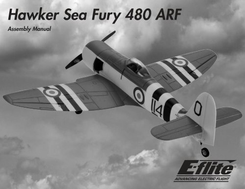
<strong>Hawker</strong> <strong>Sea</strong> <strong>Fury</strong> <strong>480</strong> ARFAssembly <strong>Manual</strong>
Contents of Kit/Parts LayoutReplacement Parts:EFL606501 FuselageEFL606502 WingEFL606503 StabilizerEFL606504 CowlingEFL606505 HatchEFL606506 Wing CoverEFL606507 SpinnerEFL606508 RocketsEFL606509 RetractsEFL606510 Fixed GearEFL606511 Pushrod SetRecommended Radio EquipmentYou will need a minimum 4-channel transmitter,receiver and four to six servos.Complete Radio SystemSPM6610 DX6i DSMX ® 6CH systemOr Purchase SeparatelySPMAR6115 AR6115 6CH DSMX MicroliteReceiverEFLRDS76 DS76 Digital Servo (4–6)EFLREX6L 6-inch (152mm) ServoExtension, Lightweight (3)EFLREX9L 9-inch (229mm) ServoExtension, Lightweight (2)(Optional Retracts)EXRA320 Y-Harness 6-inch/ReverserStandard (Optional Retracts)Required Tools and AdhesivesTools & EquipmentEFLA2505-piecePark Flyer Tool Assortment,Or Purchase SeparatelyEFLA257 Screwdriver, #1 and #2 Phillips(or included with EFLA250)Felt-tipped pen Hex wrench: 1.5mmHobby knife #11 bladesMedium CA Pin drillRazor saw RulerSandpaper Thin CADrill bit: 1/16-inch (1.5mm), 1/8-inch (3mm)Phillips screwdriver: #00, #0, #1Important Information AboutMotor SelectionWe recommend the E-<strong>flite</strong> Park 450 BrushlessOutrunner Motor, 890Kv (EFLM1400) for sportperformance or the E-<strong>flite</strong> Park <strong>480</strong> BrushlessOutrunner Motor, 1020Kv (EFLM1505) for maximumperformance.Sport Brushless Outrunner SetupEFLM1400EFLA1040LEFLAEC311EFLB21003SorTHP21003SPL25Park 450 Brushless OutrunnerMotor, 890Kv40A Pro Switch-Mode BECBrushless ESCEC3 Extension Lead with 6 inchWire, 16GA2100mAh 3S 11.1V 20C Li-Po2100mAh 3S 11.1V G6 Pro Lite25C Li-PoHigh Power Brushless Outrunner SetupEFLM1505EFLA1040LEFLAEC311EFLB22003S30orTHP21003SPL25EFLA110EFLC3020EFLAEC312Park <strong>480</strong> Brushless OutrunnerMotor, 1020Kv40A Pro Switch-Mode BECBrushless ESCEC3 Extension Lead with 6 inchWire, 16GAE-<strong>flite</strong> 3S 11.1V 2200mAh 30CLi-Po2100mAh 3S 11.1V G6 Pro Lite25C Li-PoOptional AccessoriesPower MeterCelectra 200W DC Multi-Chemistry Battery ChargerCharge Lead with 12-inch Wireand Jacks, 16AWG4 E-<strong>flite</strong> <strong>Hawker</strong> <strong>Sea</strong> <strong>Fury</strong> <strong>480</strong> ARF Assembly <strong>Manual</strong>
During the course of building your model, wesuggest you use a soft base for the building surface.Such things as a foam stand, large piece ofbedding foam or a thick bath towel will work welland help protect the model from damage duringassembly. This is not shown in the instructionsto provide the greatest detail in the photos.Fixed Gear InstallationRequired PartsFixed main gear wire (right and left)Landing gear block (2)2mm x 10mm shoulder screw (4)3mm x 6mm countersunk sheet metal screw (8)Required Tools and AdhesivesPhillips screwdriver: #0, #13. Repeat Steps 1 and 2 to assemble the secondlanding gear. (Make one left and one right)m 1. Insert the landing gear into the landing gearblock.When referencing directions (up, down, left,right top and bottom), these directions are inrelationship to the pilot sitting in the cockpitof the aircraft, unless noted otherwise.m 4. Secure the landing gear assembly in the wingusing a #1 Phillips screwdriver and four 3mm x6mm countersunk sheet metal screws per assembly.The strut is positioned toward the wing tip and isangled toward the leading edge when installedcorrectly.Before starting the assembly of your model, werecommend preparing your radio system forinstallation. This includes charging the transmitter andreceiver batteries, as well as centering the trims andsticks on your transmitter. If using a computer radio,make sure to reset a model memory and name it forthis particular model. We also recommend bindingthe transmitter and receiver at this time, followingthe instructions provided with your radio system.m 2. Use two 2mm x 10mm shoulder screws and a#0 Phillips screwdriver to secure the landing gearto the landing gear block. We highly recommend re-binding the radiosystem once all the control throws are set. This willkeep the servos from moving to their endpointsuntil the transmitter and receiver connect.E-<strong>flite</strong> <strong>Hawker</strong> <strong>Sea</strong> <strong>Fury</strong> <strong>480</strong> ARF Assembly <strong>Manual</strong>5
Retract InstallationRequired PartsServo (2) Retract linkage (2)Double-sided tape (2 pcs)Retract assembly (right and left)3mm x 6mm countersunk sheet metal screw (8)Required Tools and AdhesivesPhillips screwdriver: #0, #1 Hobby knifem 2. Apply a piece of double-sided tape onto eachservo on the side opposite the servo arm.m 4. Secure the retract assembly in the wing usinga #1 Phillips screwdriver and four 3mm x 6mmcountersunk sheet metal screws per assembly.1. Prepare the retract servos by installing the servoarms on the servos.m 3. Connect the retract linkage to the retractactuator arm.m 5. Place the retract in the UP position and insertthe retract servo in the pocket. Do not connect thelinkage to the retract servo at this time. Use theradio to move the servo arm to the UP position.Hold the linkage to the arm to make sure thelinkage aligns with the servo arm. Adjust the endpoint at the radio to align the arm with the linkage.The servos are shown with the servo armscentered. Make sure to position the servo hornso they travel equally from this center positionor your retracts may not operate correctly.6 E-<strong>flite</strong> <strong>Hawker</strong> <strong>Sea</strong> <strong>Fury</strong> <strong>480</strong> ARF Assembly <strong>Manual</strong>
m 6. Place the retract in the DOWN position anduse the radio to move the servo to the DOWNposition. Do not connect the linkage to the retractservo at this time. Hold the linkage to the arm tomake sure the linkage aligns with the servo arm.Adjust the end point at the radio to align the armwith the linkage.If you are using a 6-channel or more computer radioyou can use a separate channel for each of the retractservos. Using two channels and mixing them togetherwill give you the option for independent adjustmentof the travel adjustment of each servo. If you are notusing a computer radio with mixing, you will needto use a reversing Y-harness (EXRA320) instead.m8. Repeat Steps 2 through 7 to install the remainingretract and servo.Aileron Servo InstallationRequired PartsAileron linkage with clevis and keeper (2)Servo (2) Double-sided tape (2 pcs)Wing extension Wing6-inch (152mm) extension9-inch (228mm) extension (2) (for optional retracts)Required Tools and AdhesivesHobby knife Medium CAPhillips screwdriver: #01. Locate the wing extension and test fit it to therear of the wing. Use medium CA to glue theextension directly to the wing.m 7. Remove the servos once the end points havebeen adjusted and attach the linkage to the servo.Use a hobby knife to enlarge the hole in the servoarm if needed. Peel the backing tape off of theservo and mount it in position.E-<strong>flite</strong> <strong>Hawker</strong> <strong>Sea</strong> <strong>Fury</strong> <strong>480</strong> ARF Assembly <strong>Manual</strong>7
2. Prepare the aileron servos by installing the servoarms on the servos. Use your radio to center theseservos at this time.4. Remove the backing from the double-sided tape.Position the servo so the arm is facing toward theaileron and the outboard side off the wing. Presseach aileron servo into the openings in the wing.6. Route the leads for the aileron (and retract)servo(s) along the channel in the wing. Theextension(s) then pass to the top of the wingthrough the hole in the center of the wing.3. Apply a piece of double-sided tape onto eachservo, on the side opposite the servo arm.5. Connect a 6-inch (152mm) extension to eachaileron servo lead. If you have opted to installretracts, attach a 9-inch (228mm) extension toeach retract servo lead. Use string to secure theextension(s) so they do not unplug accidentally.7. Remove the backing from the double-sided tapeon the wing cover.8 E-<strong>flite</strong> <strong>Hawker</strong> <strong>Sea</strong> <strong>Fury</strong> <strong>480</strong> ARF Assembly <strong>Manual</strong>
8. Carefully position the wing cover on the bottomof the wing. Make sure to align the cover duringpositioning.m 10. Insert the Z-bend on the aileron linkage into theouter hole of the aileron servo horn.Main Wheel InstallationRequired PartsWheel spacer (2) Main wheel (2)Wheel axle cap (2)Required Tools and AdhesivesMedium CAThe wheel installation is the same forboth fixed gear and retracts.m 1. Slide the wheel spacer onto the landinggear axle.m 9. Use a hobby knife to enlarge the outer hole onthe aileron servo arm to accept the aileron linkage.m 11. Connect the clevis of the aileron linkage to theaileron control horn. With the radio on, it may benecessary to adjust the length of the linkage so theaileron is centered.12. Repeat Steps 9 through 11 to connect theremaining aileron linkage.E-<strong>flite</strong> <strong>Hawker</strong> <strong>Sea</strong> <strong>Fury</strong> <strong>480</strong> ARF Assembly <strong>Manual</strong>9
m 2. Slide the wheel onto the landing gear axle.Motor and Cowling InstallationRequired PartsMotor mount 6-inch (152mm) servo extensionPropellerElectronic speed controlSpinner cone Spinner washerSpinner backplate Motor with accessories1/8-inch (3mm) spacer (4)1.5mm x 10mm self-tapping screw6-inch (152mm) battery extension3mm x 10mm machine screw (4)Park <strong>480</strong>m 3. Secure the wheel using the wheel axle cap andmedium CA. Use care not to get CA between thelanding gear and wheel, which will prevent thewheel from rolling.Required Tools and AdhesivesRazor saw Phillips screwdriver: #00, #11. Attach the Park 450 motor to the mount usinga #1 Phillips screwdriver and four 3mm x 10mmmachine screws and the four 1/8-inch (3mm)spacers as shown. Use threadlock on the screws toprevent the vibrations of the motor from looseningthe screws.2. Use a razor saw to cut the length of the motormounting stick to 7/8-inch (22mm) as shown below.Park 4504. Repeat Steps 1 through 3 to install theremaining wheel.When installing the Park <strong>480</strong> motor, use a #1Phillips screwdriver, four 3mm x 10mm machinescrews and the four 1/8-inch (3mm) spacers asshown. Use threadlock on the screws to prevent thevibrations of the motor from loosening the screws.10 E-<strong>flite</strong> <strong>Hawker</strong> <strong>Sea</strong> <strong>Fury</strong> <strong>480</strong> ARF Assembly <strong>Manual</strong>
3. Lift the hatch from the fuselage as shown.Never check the motor rotation on the benchwith the propeller installed. The plane couldmove and cause serious injury. Always check themotor without the propeller to avoid injury.5. Connect the battery and servo lead extensions tothe speed control. Secure them using string to preventthem from being unplugged inside the fuselage.4. Remove the battery stop from the inside ofthe fuselage by sliding it rearward and out ofthe fuselage.7. Secure the speed control inside the motorcompartment using double-sided tape.6. Pass the battery and servo extensions into thelower hole in the fuselage and into the main radiocompartment as shown below.Important Information About Your Brushless ESCMake sure your ESC brake is programmedto Off. Also, be sure to use an ESC with theproper low-voltage cutoff and have it setcorrectly for the batteries you are using.E-<strong>flite</strong> <strong>Hawker</strong> <strong>Sea</strong> <strong>Fury</strong> <strong>480</strong> ARF Assembly <strong>Manual</strong>11
8. Connect the leads from the motor to the speedcontrol. Slide the motor mount onto the motor stick.12. Slide the cowling onto the fuselage. Press thecowling against the tape to secure it in position.9. Secure the motor mount using the 1.5mm x10mm self-tapping screw and a #00 Phillipsscrewdriver. Secure the wires inside the motorcompartment so they will not interfere with theoperation of the motor.10. Check the operation of the motor at this time.It should rotate counterclockwise when viewedfrom the front of the aircraft. If not, follow theinstructions provided with your speed control tocorrect the situation.11. Remove the backing from the double-sidedtape on both sides of the fuselage.Always balance your propeller. An unbalancedpropeller can cause vibrations to be transmittedinto the airframe, which could damage theairframe or other components as well asproduce unwanted flight characteristics.If it is necessary to enlarge the hole inthe propeller or the spinner, make sure tocheck the balance of each afterwards.13. Slide the propeller adapter into the propeller.12 E-<strong>flite</strong> <strong>Hawker</strong> <strong>Sea</strong> <strong>Fury</strong> <strong>480</strong> ARF Assembly <strong>Manual</strong>
14. The spinner backplate is then placed onthe adapter.16. Install the adapter nut, but do not tighten itat this time.18. Snap the spinner cone onto the spinnerbackplate to complete the motor assembly.15. Next, slide the supplied washer onto the adapter.17. Place the spinner assembly on the motor shaft.Check that the positioning of the assembly willallow the backplate and propeller to spin withoutrubbing on the cowling. Tighten the adapter nutonce all is well.E-<strong>flite</strong> <strong>Hawker</strong> <strong>Sea</strong> <strong>Fury</strong> <strong>480</strong> ARF Assembly <strong>Manual</strong>13
Radio Installation - FuselageRequired PartsHook and loop tape Receiver6-inch (152mm) servo extension (2) (ailerons)Servo (two required if using rudder control)Required Tools and AdhesivesPhillips screwdriver: #0 Pin drillDrill bit: 1/16-inch (1.5mm)1. Mount the rudder and elevator servos in thefuselage using a pin drill, a 1/16-inch (1.5mm)drill bit and the hardware provided with the servo.2. Plug the leads from the servos and speed controlto the appropriate outputs on the receiver. Alsoconnect the 6-inch (152mm) extensions for theailerons to the receiver.Rudder PreparationRequired PartsControl horn Control horn backplate2mm x 10mm sheet metal screw (2)Operational tail gear wire Tail wheelWheel spacer Wheel axle capRequired Tools and AdhesivesHobby knife Thin CADrill bit: 1/8-inch (3mm) Pin drillFelt-tipped pen SandpaperMedium CA3. Use double-sided tape to secure the receiver inthe fuselage as shown.Although the rudder can be installed after thestabilizer, it is much easier to do so before installingthe stabilizer. The photos show the stabilizerinstalled for reference, even though the actualinstallation will be covered later in the manual.1. Use a hobby knife to cut the rudder from the fin.Cut as close to the fin as possible for the best results.14 E-<strong>flite</strong> <strong>Hawker</strong> <strong>Sea</strong> <strong>Fury</strong> <strong>480</strong> ARF Assembly <strong>Manual</strong>
2. Use sandpaper to remove any irregularities fromthe fin and rudder.4. Cut slots in the rudder for the three rudderhinges. Use thin CA to glue the hinges half-wayinto the rudder as shown.6. Hold the rudder against the fin and use a felttippedpen to transfer the location of the hingesto the fin.3. Mount the control horn to the rudder as shownusing two 2mm x 10mm sheet metal screws, controlhorn backplate and a #1 Phillips screwdriver.5. Use a pin drill and 1/8-inch (3mm) drill bit todrill a hole for the tail gear wire in the rudder.7. Use a hobby knife to cut the slots for the rudderhinges in the fin.E-<strong>flite</strong> <strong>Hawker</strong> <strong>Sea</strong> <strong>Fury</strong> <strong>480</strong> ARF Assembly <strong>Manual</strong>15
8. Slide the tail gear wire through the tail gearbushing as shown.10. Slide the wheel spacer onto the tail gear wire.12. Secure the wheel using the wheel axle cap andmedium CA. Use care not to get CA between thetail gear wire and wheel, which will prevent thewheel from rolling.9. Test fit the rudder to the fin. Once satisfied withthe fit, use thin CA on the hinges and tail gear wireto secure the rudder to the fin. Make sure not to getCA in the tail gear assembly.11. Slide the tail wheel onto the tail gear wire.16 E-<strong>flite</strong> <strong>Hawker</strong> <strong>Sea</strong> <strong>Fury</strong> <strong>480</strong> ARF Assembly <strong>Manual</strong>
Stabilizer/Elevator InstallationRequired PartsFuselage assembly Stabilizer assembly13 7 / 32 -inch (335mm) pushrod with clevis13 9 / 16 -inch (345mm) pushrod with clevis3. Slide the stabilizer into the slot in the fuselage.Measure the distance from each stabilizer tip toeach wing tip. The measurements must be equal.If necessary, adjust the position of the stabilizer tocorrect for the alignment.5. After aligning the stabilizer to the wing, usemedium CA to glue the stabilizer in place. Doublecheck the alignment one last time before the CA fullycures. Once the CA cures, snap the joiner wire backinto the bracket at the trailing edge of the stabilizer.Required Tools and AdhesivesThin CAMedium CA1. Remove the elevators and elevator joiner wirefrom the stabilizer.4. Stand back and view the model from the rear.The wing and stabilizer must be parallel to eachother. Lightly sand the opening in the fuselage forthe stabilizer to correct for any alignment issues.6. Apply thin CA to each side of the hinge, as wellas to the elevator joiner wire.2. Place the elevator joiner wire in the slot in thefuselage for the stabilizer.E-<strong>flite</strong> <strong>Hawker</strong> <strong>Sea</strong> <strong>Fury</strong> <strong>480</strong> ARF Assembly <strong>Manual</strong>17
8. Remove the clevis from the 13 7 / 32 -inch (335mm)pushrod. Slide the pushrod into the preinstalledtube in the fuselage.10. Thread the clevis back on the pushrod wire.Connect the clevis to the elevator control horn.7. Attach both elevator halves to the stabilizer.Remember to work quickly to avoid having the CAcure before the elevator installation is complete.9. Connect the bend in the pushrod to theelevator servo horn. Position the horn so theangle between it and the servo is 90 degrees.Secure the horn to the servo.11. With the radio system on, adjust the position ofthe clevis so the elevator is parallel to the stabilizer.18 E-<strong>flite</strong> <strong>Hawker</strong> <strong>Sea</strong> <strong>Fury</strong> <strong>480</strong> ARF Assembly <strong>Manual</strong>
3. Slide the motor battery into the fuselage. Slidethe battery as far forward as possible.5. Slide the battery stop back into the fuselage. If itis not fully in position, the canopy will not fit backonto the fuselage.7. The rockets are installed by pressing them intothe precut slots in the wing cover and into the slotsin the wing.4. Connect the motor battery to the speed control.6. Place the canopy back onto the fuselage.Make sure to be clear of the propeller when connectingthe battery in case the motor starts unexpectedly.20 E-<strong>flite</strong> <strong>Hawker</strong> <strong>Sea</strong> <strong>Fury</strong> <strong>480</strong> ARF Assembly <strong>Manual</strong>
Center of GravityAn important part of preparing the aircraft for flight isproperly balancing the model.Caution: Do not inadvertently skip this step!Please balance your model inverted with the batteryinstalled. With the model inverted, lift the model at theCenter of Gravity (CG) marks molded into the wingusing your fingertips, or a commercially availablebalancing stand. The model will rest level or slightlynose down when balanced correctly. If necessary, addthe supplied clay weight to the nose or tail to achievethe correct CG.Control Throws1. Turn on the transmitter and receiver of yourmodel. Check the movement of the rudder usingthe transmitter. When the stick is moved right,the rudder should also move right. Reverse thedirection of the servo at the transmitter if necessary.2. Check the movement of the elevator with theradio system. Moving the elevator stick towardthe bottom of the transmitter makes the airplaneelevator move up.RudderThrow Measurement D/R ExpoHigh Rate13/16-inch (20mm) (Right/Left) 100 20%Low Rate1/2-inch (13mm) (Right/Left) 60 10%These are general guidelines measured from our ownflight tests. You can experiment with higher rates tomatch your preferred style of flying.Once all the control throws have been set, make sureto slide the clevis retainers over the clevises to preventthem from opening accidentally.3. Check the movement of the ailerons with theradio system. Moving the aileron stick right makesthe right aileron move up and the left aileronmove down.4. Use a ruler to adjust the throw of the elevator,ailerons and rudder. Adjust the position ofthe pushrod at the control horn to achieve thefollowing measurements when moving the sticks totheir endpoints.After the first flights, the CG position can be adjustedfor your personal preference.Measurements are taken at thewidest point on the surface.AileronsThrow Measurement D/R ExpoHigh Rate1/2-inch (13mm) (Up/Down) 100 15%Low Rate5/16-inch (8mm) (Up/Down) 60 10%ElevatorHigh Rate7/16-inch (11mm) (Up/Down) 100 20%Low Rate5/16-inch (8mm) (Up/Down) 60 15%Travel Adjust and Sub-Trims are not listedand should be adjusted according to eachindividual model and preference.NOTICE: Always re-bind the radio systemonce all the control throws are set. This willkeep the servos from moving to their endpointsuntil the transmitter and receiver connect.E-<strong>flite</strong> <strong>Hawker</strong> <strong>Sea</strong> <strong>Fury</strong> <strong>480</strong> ARF Assembly <strong>Manual</strong>21
PreflightCheck Your RadioBefore going to the field, make sure your batteriesare fully charged per the instructions included withyour radio. Charge the transmitter and motor batteryfor your airplane. Use the recommended chargersupplied with your particular radio system, followingthe instructions provided with the radio. In mostcases, the radio should be charged the night beforegoing out flying.Before each flying session, be sure to range check yourradio. See your radio manual for the recommendedrange and instructions for your radio system. Eachradio manufacturer specifies different procedures fortheir radio systems. Next, run the motor. With themodel securely anchored, check the range again. Therange test should not be significantly affected. If itis, do not attempt to fly! Have your radio equipmentchecked out by the manufacturer.Double-check that all controls (aileron, elevator, rudderand throttle) move in the correct direction.Check the radio installation and make sure all thecontrol surfaces are moving correctly (i.e., the correctdirection and with the recommended throws).Check all the control horns, servo horns, and clevisesto make sure they are secure and in good condition.Range Test Your RadioBefore each flying session, and especially with a newmodel, it is important to perform a range check. Itis helpful to have another person available to assistduring the range check. If you are using a Spektrum transmitter, please refer to your transmitter’s manual fordetailed instructions on the range check process. 1. With the model resting on the ground, stand 30paces (approximately 90 feet) away from the model.2. Face the model with the transmitter in yournormal flying position. Be sure the throttle is in thefull down position and plug the flight battery intothe speed control.3. As you move the controls, watch to be sure theairplane’s motor and controls operate smoothly.You should have total control of the model at 30paces (90 feet).4. If control issues exist, call the appropriateHorizon Product Support office (see addresseslisted in the Warranty Services section of thismanual) or go to horizonhobby.com to find a localSpektrum distributor in your country for servicewhen using a Spektrum radio system.Flying Your ModelBegin by placing the model on the ground. Check allcontrol throws and ensure everything is traveling in theright direction. Move your idle trim up until the propbegins to spin; this will be your flight idle. Taxi intoposition on the runway, facing into the wind. Applypower slowly and steer with rudder. The tail will comeup very quickly. As you apply full throttle and cometo speed, apply a slight amount of up elevator andthe <strong>Sea</strong> <strong>Fury</strong> should lift off gently and begin to climbupwards. As you climb out, release the elevator andmaintain a gentle climb to about 100 feet of altitude.Once at about 100 feet of altitude, trim the model forlevel flight at 5/8 throttle. You will find the <strong>Sea</strong> <strong>Fury</strong> tobe very gentle on the control and feel quite light on thesticks. The model is capable of all the basic aerobaticmaneuvers; loops, rolls, stall turns, inverted flight, etc.If you have no roll issues with the model, then you areready to set up for landing. We normally do a passover the runway first. Turn into the downwind leg andmanage the power at about 1/2 throttle. As you turnto base leg, you may reduce the throttle a bit andthen, when you turn onto final approach, adjust thepower to maintain a shallow descent with the model.As you come down to an altitude of about 8 feet overthe runway, begin to level the model out, and, as youget within 3 feet, you will begin to flare for landing.The <strong>Sea</strong> <strong>Fury</strong> likes to be either landed on the mains orthree pointed on the gear in a full stall. The choice isyours.We at E-<strong>flite</strong> hope you enjoy your <strong>Sea</strong> <strong>Fury</strong> as muchas we have. Happy landings!22 E-<strong>flite</strong> <strong>Hawker</strong> <strong>Sea</strong> <strong>Fury</strong> <strong>480</strong> ARF Assembly <strong>Manual</strong>
Daily Flight Checks1. Check the battery voltage of the transmitterbattery. Do not fly below the manufacturer’srecommended voltage. To do so may cause youraircraft to crash.When you check these batteries, ensure you have thepolarities correct on your expanded scale voltmeter.2. Check all hardware (linkages, screws, nuts,and bolts) prior to each day’s flight. Be sure thatbinding does not occur and that all parts areproperly secured.3. Ensure all surfaces are moving in theproper manner.4. Perform a ground range check before eachday’s flying session.5. Prior to starting your aircraft, turn off yourtransmitter, then turn it back on. Do this each timeyou start your aircraft. If any critical switches areon without your knowledge, the transmitter alarmwill sound a warning.Limited WarrantyWhat this Warranty CoversHorizon Hobby, Inc. (“Horizon”) warrants to theoriginal purchaser that the product purchased (the“Product”) will be free from defects in materials andworkmanship at the date of purchase.What is Not CoveredThis warranty is not transferable and does not cover(i) cosmetic damage, (ii) damage due to acts of God,accident, misuse, abuse, negligence, commercial use,or due to improper use, installation, operation ormaintenance, (iii) modification of or to any part of theProduct, (iv) attempted service by anyone other thana Horizon Hobby authorized service center, or (v)Products not purchased from an authorized Horizondealer.OTHER THAN THE EXPRESS WARRANTY ABOVE,HORIZON MAKES NO OTHER WARRANTY ORREPRESENTATION, AND HEREBY DISCLAIMS ANYAND ALL IMPLIED WARRANTIES, INCLUDING,WITHOUT LIMITATION, THE IMPLIED WARRANTIESOF NON-INFRINGEMENT, MERCHANTABILITYAND FITNESS FOR A PARTICULAR PURPOSE.THE PURCHASER ACKNOWLEDGES THAT THEYALONE HAVE DETERMINED THAT THE PRODUCTWILL SUITABLY MEET THE REQUIREMENTS OF THEPURCHASER’S INTENDED USE.Limitation of LiabilityHORIZON SHALL NOT BE LIABLE FOR SPECIAL,INDIRECT, INCIDENTAL OR CONSEQUENTIALDAMAGES, LOSS OF PROFITS OR PRODUCTION ORCOMMERCIAL LOSS IN ANY WAY, REGARDLESS OFWHETHER SUCH CLAIM IS BASED IN CONTRACT,WARRANTY, TORT, NEGLIGENCE, STRICT LIABILITYOR ANY OTHER THEORY OF LIABILITY, EVEN IFHORIZON HAS BEEN ADVISED OF THE POSSIBILITYOF SUCH DAMAGES. Further, in no event shall theliability of Horizon exceed the individual price of theProduct on which liability is asserted. As Horizonhas no control over use, setup, final assembly,modification or misuse, no liability shall be assumednor accepted for any resulting damage or injury. Bythe act of use, setup or assembly, the user accepts allresulting liability. If you as the purchaser or user arenot prepared to accept the liability associated with theuse of the Product, purchaser is advised to return theProduct immediately in new and unused condition tothe place of purchase.LawThese terms are governed by Illinois law (withoutregard to conflict of law principals). This warrantygives you specific legal rights, and you may also haveother rights which vary from state to state. Horizonreserves the right to change or modify this warranty atany time without notice.6. Check that all trim levers are in theproper location.7. All servo pigtails and switch harness plugsshould be secured in the receiver. Make sure theswitch harness moves freely in both directions.Purchaser’s RemedyHorizon’s sole obligation and purchaser’s sole andexclusive remedy shall be that Horizon will, at itsoption, either (i) service, or (ii) replace, any Productdetermined by Horizon to be defective. Horizonreserves the right to inspect any and all Product(s)involved in a warranty claim. Service or replacementdecisions are at the sole discretion of Horizon. Proofof purchase is required for all warranty claims.SERVICE OR REPLACEMENT AS PROVIDED UNDERTHIS WARRANTY IS THE PURCHASER’S SOLE ANDEXCLUSIVE REMEDY.E-<strong>flite</strong> <strong>Hawker</strong> <strong>Sea</strong> <strong>Fury</strong> <strong>480</strong> ARF Assembly <strong>Manual</strong>23
Warranty ServicesQuestions, Assistance, and ServicesYour local hobby store and/or place of purchasecannot provide warranty support or service. Onceassembly, setup or use of the Product has been started,you must contact Horizon directly. This will enableHorizon to better answer your questions and serviceyou in the event that you may need any assistance.For questions or assistance, please direct youremail to productsupport@horizonhobby.com, or call877.504.0233 toll free to speak to a Product Supportrepresentative. You may also find information on ourwebsite at www.horizonhobby.com.Inspection or ServicesIf this Product needs to be inspected or serviced, pleaseuse the Horizon Online Service Request submissionprocess found on our website or call Horizon to obtain aReturn Merchandise Authorization (RMA) number. Packthe Product securely using a shipping carton. Pleasenote that original boxes may be included, but are notdesigned to withstand the rigors of shipping withoutadditional protection. Ship via a carrier that providestracking and insurance for lost or damaged parcels,as Horizon is not responsible for merchandise until itarrives and is accepted at our facility. An Online ServiceRequest is available at http://www.horizonhobby.com under the Support tab. If you do not have internetaccess, please contact Horizon Product Support to obtaina RMA number along with instructions for submittingyour product for service. When calling Horizon, you willbe asked to provide your complete name, street address,email address and phone number where you can bereached during business hours. When sending productinto Horizon, please include your RMA number, a list ofthe included items, and a brief summary of the problem.A copy of your original sales receipt must be includedfor warranty consideration. Be sure your name, address,and RMA number are clearly written on the outside ofthe shipping carton.Notice: Do not ship LiPo batteries to Horizon. If youhave any issue with a LiPo battery, please contactthe appropriate Horizon Product Support office.Warranty RequirementsFor Warranty consideration, you must include youroriginal sales receipt verifying the proof-of-purchasedate. Provided warranty conditions have been met,your Product will be serviced or replaced free ofcharge. Service or replacement decisions are at thesole discretion of Horizon.Non-Warranty ServiceShould your service not be covered by warrantyservice will be completed and payment will berequired without notification or estimate of theexpense unless the expense exceeds 50% of theretail purchase cost. By submitting the item for serviceyou are agreeing to payment of the service withoutnotification. Service estimates are available uponrequest. You must include this request with your itemsubmitted for service. Non-warranty service estimateswill be billed a minimum of ½ hour of labor. Inaddition you will be billed for return freight. Horizonaccepts money orders and cashiers checks, as well asVisa, MasterCard, American Express, and Discovercards. By submitting any item to Horizon for service,you are agreeing to Horizon’s Terms and Conditionsfound on our website http://www.horizonhobby.com/Service/Request/.United States(Electronics and engines)Horizon Service Center4105 Fieldstone RdChampaign, Illinois61822 USAproductsupport@horizonhobby.com877-504-0233Online Repair Request visit:www.horizonhobby.com/service(All other products)Horizon Product Support4105 Fieldstone RdChampaign, Illinois61822 USAproductsupport@horizonhobby.com877-504-0233United KingdomGermanyFranceHorizon Hobby LimitedUnits 1-4 Ployters RdStaple TyeHarlow, EssexCM18 7NSUnited Kingdomsales@horizonhobby.co.uk+44 (0) 1279 641 097Horizon Technischer ServiceChristian-Junge-Straße 125337 Elmshorn, Germanyservice@horizonhobby.de+49 4121 46199 66Horizon Hobby SAS14 Rue Gustave EiffelZone d’Activité du Réveil Matin91230 Montgeron+33 (0) 1 60 47 44 7024 E-<strong>flite</strong> <strong>Hawker</strong> <strong>Sea</strong> <strong>Fury</strong> <strong>480</strong> ARF Assembly <strong>Manual</strong>
Compliance Information for theEuropean UnionInstructions for Disposal of WEEE byUsers in the European UnionThis product must not be disposed of with other waste.Instead, it is the user’s responsibility to dispose of theirwaste equipment by handing it over to a designatedcollection point for the recycling of waste electricaland electronic equipment. The separate collectionand recycling of your waste equipment at the timeof disposal will help to conserve natural resourcesand ensure that it is recycled in a manner thatprotects human health and the environment. For moreinformation about where you can drop off your wasteequipment for recycling, please contact your local cityoffice, your household waste disposal service or whereyou purchased the product.Academy of Model AeronauticsNational Model Aircraft Safety CodeEffective January 1, 2011A. GENERALA model aircraft is a non-human-carrying aircraftcapable of sustained flight in the atmosphere. It maynot exceed limitations of this code and is intendedexclusively for sport, recreation and/or competition.All model flights must be conducted in accordance withthis safety code and any additional rules specific to theflying site.1. Model aircraft will not be flown:(a) In a careless or reckless manner.(b) At a location where model aircraft activities areprohibited.2. Model aircraft pilots will:(a) Yield the right of way to all man carrying aircraft.b) See and avoid all aircraft and a spotter must beused when appropriate. (AMA Document #540-D-Seeand Avoid Guidance.)(c) Not fly higher than approximately 400 feet aboveground level within three (3) miles of an airport,without notifying the airport operator.(d) Not interfere with operations and traffic patterns atany airport, heliport or seaplane base except wherethere is a mixed use agreement.(e) Not exceed a takeoff weight, including fuel, of55 pounds unless in compliance with the AMA LargeModel Aircraft program. (AMA Document 520-A)(f) Ensure the aircraft is identified with the name andaddress or AMA number of the owner on the inside oraffixed to the outside of the model aircraft. (This doesnot apply to model aircraft flown indoors).(g) Not operate aircraft with metal-blade propellers orwith gaseous boosts except for helicopters operatedunder the provisions of AMA Document #555.(h) Not operate model aircraft while under theinfluence of alcohol or while using any drug whichcould adversely affect the pilot’s ability to safelycontrol the model.(i) Not operate model aircraft carrying pyrotechnicdevices which explode or burn, or any device whichpropels a projectile or drops any object that creates ahazard to persons or property.Exceptions:• Free Flight fuses or devices that burn producing smokeand are securely attached to the model aircraft duringflight.• Rocket motors (using solid propellant) up to a G-seriessize may be used provided they remain attached tothe model during flight. Model rockets may be flown inaccordance with the National Model Rocketry SafetyCode but may not be launched from model aircraft.• Officially designated AMA Air Show Teams (AST) areauthorized to use devices and practices as definedwithin the Team AMA Program Document (AMADocument #718).(j) Not operate a turbine-powered aircraft, unless incompliance with the AMA turbine regulations. (AMADocument #510-A).3. Model aircraft will not be flown in AMA sanctionedevents, air shows or model demonstrations unless:(a) The aircraft, control system and pilot skills havesuccessfully demonstrated all maneuvers intended oranticipated prior to the specific event.(b) An inexperienced pilot is assisted by anexperienced pilot.4. When and where required by rule, helmets must beproperly worn and fastened. They must be OSHA,DOT, ANSI, SNELL or NOCSAE approved or complywith comparable standards.B. RADIO CONTROL (RC)1. All pilots shall avoid flying directly over unprotectedpeople, vessels, vehicles or structures and shall avoidendangerment of life and property of others.2. A successful radio equipment ground-range checkin accordance with manufacturer’s recommendationswill be completed before the first flight of a new orrepaired model aircraft.E-<strong>flite</strong> <strong>Hawker</strong> <strong>Sea</strong> <strong>Fury</strong> <strong>480</strong> ARF Assembly <strong>Manual</strong>25
3. At all flying sites a safety line(s) must be established infront of which all flying takes place (AMA Document#706-Recommended Field Layout):(a) Only personnel associated with flying the modelaircraft are allowed at or in front of the safety line.(b) At air shows or demonstrations, a straight safetyline must be established.(c) An area away from the safety line must bemaintained for spectators.(d) Intentional flying behind the safety line isprohibited.4. RC model aircraft must use the radio-controlfrequencies currently allowed by the FederalCommunications Commission (FCC). Only individualsproperly licensed by the FCC are authorized tooperate equipment on Amateur Band frequencies.5. RC model aircraft will not operate within three(3) miles of any pre-existing flying site without afrequency-management agreement (AMA Documents#922- Testing for RF Interference; #923- FrequencyManagement Agreement)6. With the exception of events flown under officialAMA Competition Regulations, excluding takeoff andlanding, no powered model may be flown outdoorscloser than 25 feet to any individual, except for thepilot and the pilot’s helper(s) located at the flight line.7. Under no circumstances may a pilot or other persontouch a model aircraft in flight while it is still underpower, except to divert it from striking an individual.This does not apply to model aircraft flown indoors.8. RC night flying requires a lighting system providingthe pilot with a clear view of the model’s attitude andorientation at all times.9. The pilot of a RC model aircraft shall:(a) Maintain control during the entire flight,maintaining visual contact without enhancement otherthan by corrective lenses prescribed for the pilot.(b) Fly using the assistance of a camera or First-PersonView (FPV) only in accordance with the proceduresoutlined in AMA Document #550.C. FREE FLIGHT1. Must be at least 100 feet downwind of spectatorsand automobile parking when the model aircraft islaunched.2. Launch area must be clear of all individuals exceptmechanics, officials, and other fliers.3. An effective device will be used to extinguish any fuseon the model aircraft after the fuse has completed itsfunction.D. CONTROL LINE1. The complete control system (including the safetythong where applicable) must have an inspection andpull test prior to flying.2. The pull test will be in accordance with the currentCompetition Regulations for the applicable modelaircraft category.3. Model aircraft not fitting a specific category shall usethose pull-test requirements as indicated for ControlLine Precision Aerobatics.4. The flying area must be clear of all utility wires orpoles and a model aircraft will not be flown closerthan 50 feet to any above-ground electric utility lines.5. The flying area must be clear of all nonessentialparticipants and spectators before the engine isstarted.26 E-<strong>flite</strong> <strong>Hawker</strong> <strong>Sea</strong> <strong>Fury</strong> <strong>480</strong> ARF Assembly <strong>Manual</strong>
Building and Flying NotesE-<strong>flite</strong> <strong>Hawker</strong> <strong>Sea</strong> <strong>Fury</strong> <strong>480</strong> ARF Assembly <strong>Manual</strong>27
TM© 2011 Horizon Hobby, Inc.horizonhobby.comwww.e-<strong>flite</strong>rc.comE-<strong>flite</strong>, Z-Foam, EC3, Celectra, and the Horizon Hobby logo are trademarks or registeredtrademarks of Horizon Hobby, Inc.DSMX is a trademark of Horizon Hobby, Inc., registered in the U.S.The Spektrum trademark is used with permission of Bachmann Industries, Inc.All other trademarks, service marks and logos are the property of their respective owners.32497 Created 10/2011