YELLOW JACKET ®
YELLOW JACKET ®
YELLOW JACKET ®

Create successful ePaper yourself
Turn your PDF publications into a flip-book with our unique Google optimized e-Paper software.
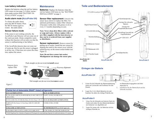
Low battery indicationReplace the batteries when the red low batteryLED comes on (see page 3). Follow instructionsunder section titled "BATTERY IN-STALLATION" on page 3.MaintenanceBatteries: Replace the batteries when thered low battery LED turns on. See “BATTERYINSTALLATION” on page 3.Teile und BedienelementeUV-LED-LeuchtenAudio alarm mute (AccuProbe UV)To silence the audio alarm,press the MUTE button. Pressthe MUTE button again torestore the audio alarm.Sensor failure modeIf the sensor is not working correctly, theAccuProbe Leak Detector will not come out ofthe warm-up mode. (Some competitive unitswithout this function will not alert you that thesensor is malfunctioning or has failed.)If the AccuProbe detector does not come outof warm-up, first be sure the sensor is pluggedin all the way. If that does not correct the situation,replace the sensor.Sensor filter replacement: Unscrew thesensor tip as shown to replace the filter. Foroptimum performance, replace filter wheneverit becomes visibly dirty with grease or oil orevery 2-3 months (depending on use).Note: Never clean dirty filters with a solventor soap and water. Always replace with anew filter supplied with the leak detector orthey can be re-ordered from your supplieror distributor.Sensor replacement: Remove sensor bypulling out of socket. Install the new sensor byaligning the notch in the sensor cover with theraised keyway on the sensor socket holder (seeFigure 2).Note: Do not force sensor into socket.Misalignment can damage the sensor pins.Digital SmartAlarm UV/LED EIN/AUSStummschaltungBeheizter SensorBlinkende LEDFlexible SondeAlarmlautsprecherAnzeige für schwacheBatterieAnzeige derEmpfindlichkeitsstufeEinstellung/Auswahl derEmpfindlichkeitEIN/AUSNetzadapterbuchseUnscrew tip toreplace filterPush straight on (do not twist) to install sensorFilterKeyway alignmentAccuProbe UV -SpitzeEinlegen der BatterieAccuProbe UVAccuProbe IIAccuProbe UVFigure 2Pull straight out (do not twist) to remove sensorPartial list of detectable SNAP* listed refrigerantsR-12 ALTERNATIVES R-22 ALTERNATIVESR-134a, R-401A (MP-39), R-401B (MP-66), R-401C (MP-52), R-406A (GHG)R-407C, R-410A, R-410B, R-507R-414A (GHG-X4), R-414B (Hot Shot), R-416A (Frig C, FR-12) R-113, R-13B & R-503 ALTERNATIVESR-409A (FX-56), Freeze 12, Free Zone, GHG-X5, GHG-HP,IKON 12R-403B, R-508A, R-508BR-502, R-500 ALTERNATIVESHC REFRIGERANTS (not SNAP approved)R-402A&B, R-404A, R-407A, R-408A, R-411A&B, R-507 R-290, R-600A, R-170/R-290, R-600A/R-290* SNAP (Significant New Alternatives Program) an EPA program for ozone depleting refrigerants for mobile and stationary A/C systems1. Lösen Sie die Schraube der Batterieabdeckungunten am Lecksucher und Entfernen Sie denDeckel.2. Legen Sie 4 AA-Alkali-Batterien ein undbeachten Sie dabei die richtige Polarität, dieAccuProbe II1. Lösen Sie die Schraube am hinteren Ende desGeräts und ziehen Sie den Batteriefachdeckelmit Scharnier wie abgebildet auf.2. Legen Sie immer alle vier Batterien mit derrichtigen Polarität ein.im Batteriefach angegeben und obenangezeigt ist.3. Installieren Sie das Batteriefach und dieSchraube anziehen.63